Embed Size (px)
Citation preview
II Ill
k • .
NLSFLIGHT SIMULATION LABORATORY
(FSL) DOCUMENTATION
_ 1_
FINAL REPORT
https://ntrs.nasa.gov/search.jsp?R=19950018019 2020-03-29T17:10:50+00:00Z
:'" TABLE OF CONTENTS
1.0
2.0
3.0
3.1
3.2
3.3
3.4
3.5
3.6
4.0
4.1
4.1.1
4.1.2
4.1.3
4.1.4
4.2
4.2.1
4.2.2
4.3
4.3.1
4.3.2
4.3.3
4.3.4
4.4
5.0
5.1
INTRODUCTION .......................................................................................... 1
FSL DOCUMENTATION/SYSTEM DESIGN ............................................. 1
FSL DOCUMENTATION CONVERSION/TRANSLATION ...................... 1
FSL Documentation Tree ................................................................................ 2
FSL Design Document .................................................................................... 3
FSL Requirement Document .......................................................................... 3
FSL Documentation Search Capabilities ........................................................ 4
FSL Hardware ................................................................................................. 4
FSL Software .................................................................................................. 4
ELECIRONIC DOCUMENTATION SYSTEM DESIGN AND
IMPLEMENTATION ..................................................................................... 4
Electronic Documentation System Local Area Network (LAN) .................... 11
High Speed Router .......................................................................................... 11
Fiber Distributed Data Interface (FDDI) ........................................................ 14
Ethernet Communication Network ................................................................. 14
Synchronous Communication Network .......................................................... 14"
Electronic Documentation System Software .................................................. 14
Integrated File Management System (IFM) .................................................... 15
Document Management System (DM) ........................................................... 16
FSL Documentation System Database Server ................................................ 16
Documentation System File Servers ............................................................... 16
Database Server .............................................................................................. 17
Documentation System Plotting/Printing ....................................................... 17
Documentation Storage ................................................................................... 17
FSL Electronic Documentation System Network Nodes ................................ 17
electronic documentation system verification ................................................ 18
Software Comparison & Test Results ............................................................. 18
6.0 CONCLUSION ............................................................................................... 19
APPENDIX A ................................................................................................................. A- 1

:" LIST OF FIGURES
Figure 2.0-1.
Figure 4.1-1.
Figure 4.1.1-1.
Figure A-1.
Figure A-2.
Primary FSL Test Configuration .................................................... 2
Backbone Concentrator Node Architecture ................................... 13
Symmetric Multiprocessor Architecture ........................................ 13
IES System Network ...................................................................... 2
FSL Functional Block Diagram ..................................................... 3
Table 4-1.
Table 4-2.
Table 4-3.
Table 4-4.
Table 4-5.
Table 4-6.
Table 4-7.
LIST OF TABLES
I.AN Hardware and Software ......................................................... 5
Software and Hardware Required for Task UI ............................... 6
Electronic Documentation System for Task IV ............................. 7
Hardware and Software for Task IV .............................................. 8
Hardware and Software Required for Task VI ............................... 9
Hardware and Software for Task VII ............................................. 10
Miscellaneous Hardware and Software .......................................... 10
ii
NLS FLIGHT SIMULATION LABORATORY (FSL) DOCUMENTATION
1.0 INTRODUCTION
The Flight Simulation Laboratory (FSL) is located at the Marshall Space Flight Center in
building 4476. The laboratory consists of a mix of both engine hardware components and
component models (i.e., the engine control architecture implemented in the simulation
laboratory).
The NLS Engine Avionics Flight Simulation Laboratory Documentation Task includes both a
documentation system and a documentation data set in an electronics format which is used to
represent various engine configurations including project redline procedures, updates and
approval cycles.
2.0 FSL DOCUMENTATION/SYSTEM DESIGN
The FSL Electronics Documentation System Design consists of modification and utilization of
the MSFC Integrated Engineering System (IES), translation of the existing FSL documentation
to an electronic format, and generation of new drawings to represent the Engine Flight
Simulation Laboratory design and implementation. Figure 2.0-1 shows the FSL Functional
Block Diagram, which describes the engine simulation laboratory.
The intent of the electronic documentation is to provide ease of access, local print/plot
capabilities, as well as the ability to correct and/or modify the stored data by network users who
are authorized to access this information.
3.0 FSL DOCUMENTATION CONVERSION/TRANSLATION
The original Requirements Document, Design Document, and various Functional Block
Diagrams for the FSL were scanned and stored as PostScript files for fast viewing. Every
paragraph in the FSL Design Document was stored as a separate file in its individual native
format. These items were entered into the IES database using the MSFC Integrated File
Management System (WM) and/or MSFC Document Management System (DM/Manager)
Software Tools. This enables the authorized users to view the documentation from any terminal
that is attached to the server network, while giving a controlled access to features and options;
such as adding, deleting, changing and/or redlining of the documentation.

I il "
I nO<r._ I'_ ' _ _ I u_
\ ..................... J ..................... ; _1 • ,i;"
,......................_ ................... _SOLENOID/IGHITOR _ , _ _1
STATES _-_r_222-_
Ii'!_i_i_iI
li_i!:i_ii:ii:!l

3.1 FSL Documentation Tree
A tree diagram is provided for this documentation as a quick reference, which may be found very
helpful by users not familiar with the FSL project or the methods of viewing the simulator
design. This diagram depicts the different levels, and items of the documentation task. The
diagram can be used as a guide to locate the information and/or to find the filenames/item
numbers of the items of interest for use as the search criteria. Figure A-I drawing 97M54311,
Sheet 2, shows a top level representation of the FSL documentation tree diagram. See Appendix
A for a drawing of the tree diagram. Figure A-l, drawing 97M54311, Sheet 1, shows the
functional block diagram for the FSL. A complete tree diagram is included for future reference
with each element shown as a separate diagram.
3.2 FSL Desi_gn Document
The FSL Design Document describes the laboratory design and operational modes for testing an
engine controller, electromechanical actuation subsystem, sensor simulators and engine models.
The purpose of this document is to describe an FSL design which can be used to exercise real-
time simulation programs based on math models of liquid propellant rocket engines. The intent
of the document was to show a configuration to evaluate the NLS STME engine but is easy to
reconfigure to test any engine model and associated hardware-in-the-loop.
The FSL Design Document has been converted to an electronic format and placed on the IES
electronic documentation system utilizing the MSFC Integrated File Management System (IFM).
Figure 3.2-1 shows the laboratory primary test configuration as shown in the design document.
This configuration can be viewed by selecting page 8 while viewing the electronic version of the
document in IFM.
3.3 FSL Reo_uirement Document
The Requirements Document was scanned and entered in the IFM system for futm_ references
and any activities relevant to the engine laboratory design. This document was originally
generated with the requirement for developing an engine simulator based on the National Launch
System (NI_) engine requirements generated from documents supplied by NASA and the
Aerojet Company.
3

The Requirements Document does not represent a true final configuration of the laboratory and
should not be used as a document to represent the design. Only the Design Document should be
used when software and hardware capabilities are being investigated for developing the engine
hardware-in-the-loop laboratory. A new requirements document should be generated when a
laboratory configuration is being developed for a new engine configuration or avionics system.
3.4 FSL Documentation Search Caoabilities
A search capability is included in the electronic documentation systems to ensure a fast access to
the stored data. For example, to view the FSL test article grounding and isolation system, either
the item description or the item number can be used as the search criteria.
3._
The FSL hardware consists of a complement of simulation hardware and interfaces to
accommodate a set of vehicle engine hardware components including sensors, controllers,
solenoids, and actuators. Figure A-1 shows the FSL functional block diagram. Each block
represents a part of the engine simulator or interface equipment and the engine controller. Each
hardware item can be accessed by referencing the FSL tree diagram and the system hardware
item number. For example, the real-time engine hardware can be accessed by looking at Figure
A-1. The FSL functional diagram is protected and represents the NLS STME engine
configuration. It can be checked-out from WM and modified for a new engine configuration, by
an Authorized User.
3.6 l_ffl..S_m_r.e
The FSL software consists of both applications and system software. The applications software
also includes two engine models which were used to test the FSL capabilities. Utilizing the tree
diagram, this software can be viewed in WM under item 97M54311 (see Appendix A).
4.0 ELECTRONIC DOCUMENTATION SYSTEM DESIGN AND
IMPLEMENTATION
The MSFC Integrated Engineering System 0ES) has been enhanced and used to store and
display the existing documentation (drawings, specifications, engine math models, and data sets
used in the design of the FSL) to an Integrated File Management 0FM) system. Figure 2.0-1
shows the functional block diagram of the FSL which was used as a data entry to the MSFC IES
and the File Management System for providing the on-line interactive operations nodes.
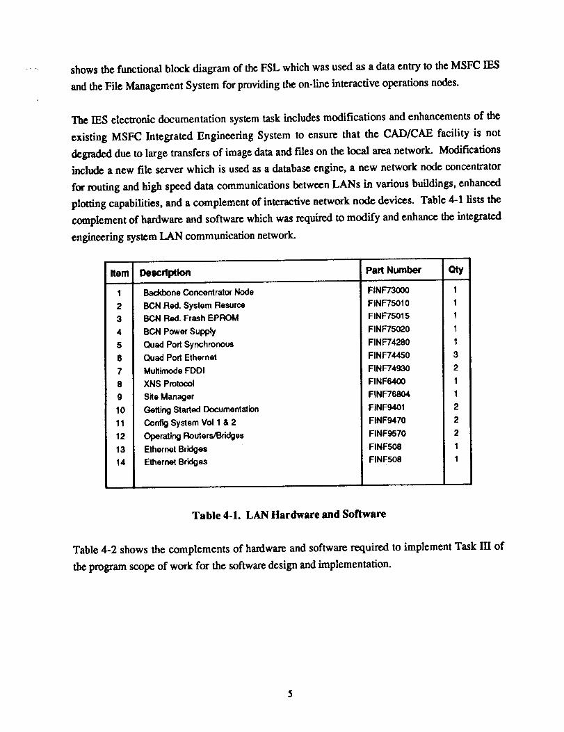
The IES electronic documentation system task includes modifications and enhancements of the
existing MSFC Integrated Engineering System to ensure that the CAD/CAE facility is not
degraded due to large transfers of image data and files on the local area network. Modifications
include a new file server which is used as a database engine, a new network node concentrator
for routing and high speed data communications between LANs in various buildings, enhanced
plotting capabilities, and a complement of interactive network node devices. Table 4-1 lists the
complement of hardware and software which was required to modify and enhance the integrated
engineering system LAN communication network.
Item
1
2
3
4
5
6
7
8
9
lo
11
12
13
14
Description Part Ntwnber
Backbone Concentrator Node
BCN Red. System Resurce
BCN Red. Frash EPROM
BCN Power Supply
Quad Port Synchronous
Quad Port Ethernet
Multimode FDDI
XNS Protocol
Site Manager
Getting Started Documentation
Config System Vol 1 & 2
Operating Routers/Bridges
Ethernot Bridges
Ethernet Bridges
Qty
FINF73000 1
FINF75010 1
FINF75015 1
FINF75020 1
FINF74280 1
FINF7¢450 3
FINF74930 2
FINF6400 1
FINF76804 1
FINF9401 2
FINF9470 2
FINF9570 2
FINF508 1
FINF508 1
Table 4-1. LAN Hardware and Software
Table 4-2 shows the complements of hardware and software required to implement Task III of
the program scope of work for the software design and implementation.

Itom Descdptlon Part Number
1 Asterx Word and Graphicvs
2 Asterx FitterPack
3 PEM Disk-2.1GB
PEM Disk-2,1GB
PEM Disk-2.1GB
PEM Disk-2.1GB
4 Internal Disk Assembly
Internal Disk Assembly
Internal Disk Assembly
Internal Disk Assembly
5 Fixed Disk-2.1GB
Fixed Disk-2.1GB
Fixed Disk-2,1GB
Fixed Disk-2.1GB
F=ed Disk-2.1GB
Fixed Disk-2.1GB
6 DB _ Runtime
7 X DMANDS Runtime
8 Network Fde System (NFS)
9 64MB Memory Expansion
64MB Memory Expansion
64MB Memory Expansion
64MB Memory Expansion
64MB Memory Expansion
64MB Memory Expansion
oty
SSBT32800 5
SSBT33100 5
FDSK379 1
FDSK379 1
FDSK379 1
FDSK379 1
FDSK296 1
FDSK296 1
FDSK296 1
FDSK296 1
FDSK380 1
FDSK380 1
FDSK380 1
FDSK380 1
FDSK380 1
FDSK380 1
SNAV20600 6
SRBT05400 6
SSAAZ0810O 6
FMEM101 1
FMEM101 1
FMEM101 1
FMEM101 1
FMEM101 1
FMEM101 1
Table 4-2. Software and Hardware Required for Task HI
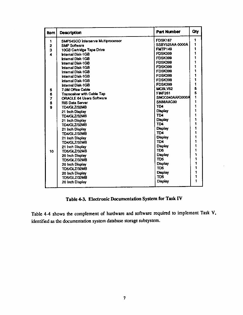
Table 4-3 shows the complement of hardware and software required to implement Task IV of the
electronic documentation system including a database server, ORACLE database system and
nodes for the interactive documentation system.
6
_em
12
34
5678
9
10
Description Part Number
SMP54SCO Interserve MultiprocessorSMP Software
10(38 Cartridge Tape Ddveinternal Disk-lGBInternal Disk-lGBInternal Disk- 1GBInternal Disk-lGBInternal Disk-1GBInternal Disk-lGBInternal Disk-lGBInternal Disk-lGB7.0M Office Cable
Transceiver with Cable TapORACLE 64 Users Software
oty
RIS Data Server_MB
21 Inch DisplayTD4/GLZ/32MB
21 Inch DisplayTD4/GLZ/32MB
:)I Inch _s_ayTD4/GLZ/32MB
21 Inch DisplayTD4/GLZ/32MB
21 Inch DisplayTD5/GLZ/32MB
20 Inch Display_MB
20 Inch Disl_ayTDSff_::_4_TJ32MB
20 Inch [_splayTDSK_LZJ32MB
20 Inch Display
FDSK187 1SSBY525AA-0000A 1FMTP149 1FDSK399 1
FDSK399 1FDSK399 1FDSK399 1FDSK399 1FDSK399 1FDSK399 IFDSK399 1MCBLVS2 5FINF261 5SNCCO4OAAK0000.a 1SN88AACO0 1TD4 1
Dis_y 1TD4 1
Display IIO4 I
DisplayTD4 I
Display ITD4 I
Display ITD5 I
Display 1TO6 1
Display 1TD5 1
i:)_olay 1TD5 1
Display 1
Table 4-3. Electronic Documentation System for Task IV
Table 4-4 shows the complement of hardware and software required to implement Task V,
identified as the documentation system database storage subsystem.

Item
I
2
3
4 TD5/GLZ/32MB
20 Inch Display
TD5/GLTJ32MB
2o InchD_ayTDS_LZ/32MB
2O Inch Display
TD5_L7J32MB
2OInchDL_lay5 Trancelver with Cable Tap
Descdptlon Part Number
EXALT
DM/DB Access Runtime
7.0M Office Cable
Qty
SSBY537AA-0100A 13
SNBX385AB-0500A 13
MCBLV52 5
TD5 1
TD5 1
Di_zyTD5 1
Disp4ay 1
TD5 1
FINF261 8
Table 4-4. Hardware and Software for Task IV
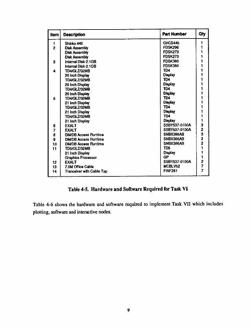
Table 4-5 shows the complement of hardware rcquir_ to implement Task VI which is identified
as a part of the network node development subsystem.
Item
1 Shinko 445
2 Disk AssemblyDisk AssemblyDisk Assembly
3 Internal Disk-2.1GBInternal Disk-2.IGB
4 TD4,_LZ/32MB
2O Inch Disl_ayTD4/GLZ/'32MB
20 Inch Disl_aYTD4/PoLZ/32MB
2oInchDL,day5 TD4/GLZ/32MB
21 Inch DisplayTD4,GLTJ32MB
21 Inch Display_MB
21 InchDi_ay6 EXALT7 EXALT8 DM/DB Access Runtime9 DM/DB Access Runtime10 DM/DB Access Runtime11 TD5K_LZ/32MB
21 Inch DisplayGraphics Processor
12 EXALT13 7.0M Office Cable
14 Tranceiver with Cable Tap
I)escrlptlon Part Number Qty
CHCS44,5 1FDSK296 1FDSK273 1FDSK273 1
FDSK380 1FDSK380 1TD4 1
Display 1TD4 1
Disptay 1"rD4 1
Display I"1"O4, I
Display ITD4 I
Dbplay 1TD4 1
Display 1SSBY537-0100A 3SSBY537-0100A 2
SNBX386AB 3SNBX386AB 2SNBX386AB 2TD5 1
Display 1GP 1SSBY537-0100A 2MCBLV52 7FINF261 7
Table 4-5. Hardware and Software Required for Task VI
Table 4-6 shows the hardware and software required to implement Task VII which includes
plotting, software and interactive nodes.
9

bm Description Part Number
1 Shinko 745
2 Disk Assembly3 Internal Disk-2.1GB
Internal Disk-2.1GB4 _MB
2O Inch Disi_ayTD4_LZJ32MB
20 Inch DisplayTD4/GLZ/32MB
20 Inch Display5 EXALT6 DM/DB Access Runtime
7 TD5/GLZJ32MB
21 Inch D_splay_MB
InchD s ay_MB
21 Inch Display8 DM/DB Access Runtime9 7,0M Office Cable
10 Tranceiver with Cable Tap
cay
FPLT793 1FDSK296 1FDSK381 1FDSK381 1TD4 1
Display ITD4 I
Display 1TD4 1
Display 1SSBY537AA-0100A 6SNBX386AB 3TD5 1
Display 1TD5 1
Display 1TDS 1
Display 1SNBX386AB 3MCBLV52 6FINF261 6
Table 4.6. Hardware and Software for Task VII
Table 4-7 shows tic miscellaneous complement of hardware and software required to complete
the documentation and system design task.
Item i
1
2
3
4
5
6
7
8
9
10
11
12
13
14
Description Part Number
MCBL79020 Meter Teflon Drop
Microsoft Office Software
M'K:rosoftOffice Software
Microsoft Office Software
Ethemet Mapler CardSound Card for TD
Sound Card for TD
Sound Card for TD
BIN/BCN V8 1 AN SUITE
kCmrosoftSystem MGMT
M'mrosoftSQL Server
Microsoft Systems MGMT
Microsoft Windows NT
Castle Rock,,SNMP Net
FINF760
FINF75200-OA
FINF75200-0A
FINF75200-0A
41019VO80
oty
25
1
1
1
1
1
1
1
1
1
1
10
2
1
Table 4-7. Miscellaneous Hardware and Software
10

'" 4.1 Electronic Documentation System Local Area Network (LAN)
Figure A-2 shows the IES communication connectivity network with access paths to various
laboratories and interactive network nodes. The FSL basic documentation system design
consists of 25 nodes but can accommodate many additional nodes depending on the Integrated
Engineering System complement of network node interactors. The communication network
consists of a 1 GB backbone with TCP/IP routing and bridging. A symmetric multi-processor
architecture utilizing three basic components consisting of link modules, processor modules and
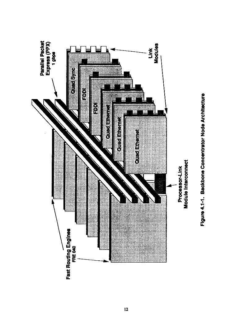
interconnects is used to develop the backbone concentrator node. Figui'¢ 4.1-1 shows the
symmetric multi-processor architecture.
4.1.1 Hi,,h Sneed Router
The router backbone used for the IES node communications task consists of LAN connectivity
for both Ethcmet/802.3 and FDDI. Multi-protocols include both TCP/IP and Novel IPX.
The router architecture includes a symmetric multi-processor which distributes the processing
power to each network interface module as shown in Figure 4.1.1-1. Each network interface
module has its own dedicated processor module which performs all routing processing tasks.
The routing information base and protocol is replicated on each processor module.
Network growth can bc accommodated by simply adding network interface modulcs. No central
processor is necessary for the routing task.
The backbone concentrator node supports 52 LAN/WAN interfaces and up to 13 FDDI
communication channels. Expansion capabilities exist for additional FDDI or Quad Ethernet
modules which can b¢ integrated to allow additional LANs and nodes.
11
E
._1 0.,.uO
m
IE
.o
|
iC0
®CO.12
Uam
|
m
U.
12

13

4.1.2 Fiber Distributed Data lnterfacf (FDDB
The FDDI modules are used on the SMP database engine and the IAN backbone. See Figure
4.1-1 for a block diagram of the LAN and Backbone Concentrator Node (BCN). The FDDI is a
I00 Mbps LAN that uses the fiber-optic media for data communications. This configuration uses
10 mbps Ethernet data communications for the SMP server but will be upgraded to 100 mbps
when the FDDI module is installed in the BCN. The purpose of this upgrade is to increase the
database communication throughput by a factor of ten. The two FDDI modules are shown in
Figure 4.1-1 which shows the architecture for the backbone concentrator node.
4.1.3 Ethernet Communication Network
Three quad Ethernet interface modules are used for data communication between the
laboratories. This interface supports IEEE 802.3 and version 1.0/2.0 Etbernet frame formats.
The data communication for this module is 10 Mb and the transmission media is fiber cables
between the various laboratories. The LAN protocol support includes both TCP/IP and Novel
IPX. Figure 4.1-1 shows the backbone concentrator node architecture and the three quad
Ethemet link modules.
4.1.4 Synchronous Communication Network
A quad synchronous communication network module is included in the backbone concentrator to
perform the existing functionality required for building 4656 and off-site serial data
communication task. This link serves to function up to T1 (64 Kbs) communication capabilities.
4.2 Electronic Documentation System Software
Electronic Documentation is a process of managing or controlling documents and drawings (i.e.,
a type of filing system). In a manual paper-based environment, a user will organize individual
pieces of data into f'de folders and store those groups of folders and other data elements in a file
cabinet.
A paperless Electronic Documentation System parallels a manual effort and provides a file
cabinet, fde folders, and the ability to store groups of files within the file folders. It also
simplifies the task of managing distributed information in large scale engineering/management
environments by enabling the diverse user population to locate, access and control data with
14
organized efficiency and at the same time provides the ability to create fluent links between
various document formats, incompatible databases and different computing equipment attached
to the IES network or to the bridged combinations of similar networks that obey the same
protocol.
The FSL paperless Electronic Documentation was accomplished utilizing the Integrated File
Management System ¢IFM_ and the Document Management System fDM) software packages.
These filing systems also track location, version, ownership and file integrity through a series of
catalogs in a relational database system. The storage and file security is maintained on library
check-in check-out basis by both systems. The following paragraphs describe the IFM and the
DM System.
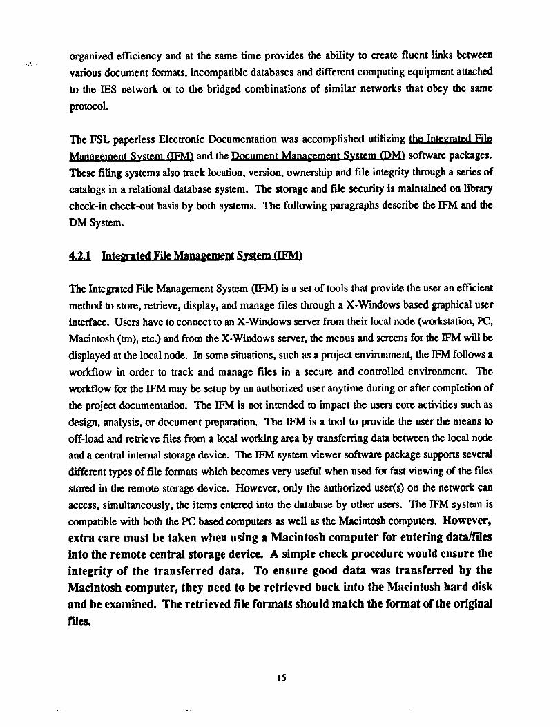
4.2.1 lnt _egrated File Management System (IFM}
The Integrated File Management System 0FM) is a set of tools that provide the user an efficient
method to store, retrieve, display, and manage files through a X-Windows based graphical user
interface. Users have to connect to an X-Windows server from their local node (workstation, PC,
Macintosh (tm), etc.) and from the X-Windows server, the menus and screens for the IFM will be
displayed at the local node. In some situations, such as a project environment, the IFM follows a
workflow in order to track and manage files in a secure and controlled environment. The
workflow for the WM may be setup by an authorized user anytime during or after completion of
the project documentation. The IFM is not intended to impact the users core activities such as
design, analysis, or document preparation. The IFM is a tool to provide the user the means to
off-load and retrieve fries from a local working area by transferring data between the local node
and a central internal storage device. The IFM system viewer software package supports several
different types of file formats which becomes very useful when used for fast viewing of the files
stored in the remote storage device. However, only the authorized user(s) on the network can
access, simultaneously, the items entered into the database by other users. The IFM system is
compatible with both the PC based computers as well as the Macintosh computers. However,extra care must be taken when using a Macintosh computer for entering data/rdes
into the remote central storage device. A simple check procedure would ensure the
integrity of the transferred data. To ensure good data was transferred by the
Macintosh computer, they need to be retrieved back into the Macintosh hard disk
and be examined. The retrieved file formats should match the format of the original
riles.
15
Document Management System (DM)
The Document Management System (DM) is a set of tools that provide comprehensive file
management on a network. The members of the DM family work together to provide simple fde
access, file viewing, non-destructive file redlining, data collection or capture, workflow control,
and file security. The DM is a user-friendly windows based product that works in concert with
the Intergraph/Network File Manager (I/NFM) to organize information about the work
environment, its users, and its f'fles, storing this information in any location that is accessible to
the network. In some situations, such as a project environment, the DM can be setup by an
authorized user to follow a workflow in order to track and manage files in a secure and
controlled environmenL The DM, like the IFM, is designed to provide the user the means to off-
load and retrieve data stored at the central storage device from a local working area, rather than
impacting the users core activities such as design, analysis, or document preparation. The DM
system view/redline software package supports several different types of file formats which
becomes very useful when used for fast viewing of the files stored in the remote storage device.
However, only the authorized users on the network can access the files entered into the database
by other users. The DM system is compatible only with the PC based computers, at the present
time. However, the next version of DM will support the Macintosh computers also.
4.3 FSL Documentation System Database Server
The Electronics Documentation System database server for the IES was installed on a special
server LAN and was implemented in Building 4487, room A183. The server was implemented
with 4 Pentium microprocessors and is identified as ISMP05, IFMSMP1. See Figure A-2 in the
Appendix A for a block diagram of the Integrated Engineering System network. The data
communication system is a 10 Mb/s Ethernet LAN. However, this network is in the process of
being upgraded to a separate FDDI module which has been installed in the backbone
concentrator node LAN communication subsystem. This will increase the speed of the database
engine to a 100 Mb/s communication link for passing data files to the different network nodes.
4.3.1 Documentation System File Servers
Figure A-2 in Appendix A shows the complement of servers for the IES and the distribution to
the various buildings.
16

. 4.3.2 Database Server
The database server is located in Building 4487/A183 and is used for all database functions
regardless of workstation node location. The Oracle relational database management system is
installed on this server.
4.3.3 Documentation Sy_¢m PIottin_gflPrinting
Both the Integrated File Management, IFM, and the Document Management, DM, systems
provide the users the means to plot viewable item types to a selected plot queue. A viewable file
is defined as a file of type: Postscript, TIFF, IGDS, BLKIM, tg4, etc., that can be viewed on
screen by selecting either the View or the Redline buttons from the IFM menu screen or selecting
the view/redline option from the DM windows. The plot option for the IFM is provided in the
menu screen while in DM can be selected either by choosing the print button from the toolbar or
selecting the Print option from under the File. In any case, a dialog box appears with simple
instructions to follow for plotting fries to the desired plot queue. The items stored in any other
format (i.e., native formats) can be printed to a local printer. To print a non-viewable item to the
local printer, the item must be either checked-out or copied-out to the local node using either the
IFM or the DM System. This will place a copy of the file attached to that item on the local hard
drive. The local file can then be opened and be printed to the local printer, using the original
application software package.
4.3.4 Documentation Storage
Documentation files are stored on the five X-Window servers which are distributed on the IES
network of LANs. In general, the fries are stored on the X-Windows file server in the same
building. Some files are also stored on the database engine.
4.4 FSL Electronic Documentation System Network Nodes
The FSL Electronic System Documentation Nodes consist of the Database Engine (Server),
Archival Storage Units, Workstations and ancillary support computational resources, Plotters,
PC's and clones and Apple Macintosh Personal Computers tied together into the IES network
and optimized for using the shared resources and to create an efficient computing environment
for engineers and managers for exchanging design information in real time, as well as tasks in
the concurrent or integrated engineering environments in the areas of review and redlining of
17
documents,integrateddocumentpublishingand CAD documentconferencingactivities. The
increasing number of nodes on the IES network is currently estimated at 300+.
The FSL Electronic Documentation can be accessed from any node on the IES network, provided
that the user is authorized to access the database for the FSL project.
5.0 ELECTRONIC DOCUMENTATION SYSTEM VERIFICATION
The paperless FSL Electronic Documentation was tested from several locations using different
types of computers such as: Macintosh, PC based processors, and MSFC's InterAct 3000
machines. The results were as expected. Every node on the network was capable of successfully
accessing the database, transferring data files for storage on the remote device as well as
retrieving data for viewing and redlining of documents. Both the DM and the IFM systems were
QA'ed, corrected, and verified to perform as expected by the NLS Request For Proposal
document, and as stated in the NLS Program Deseope Design Document.
5.1 Software Comparison & Test Results
The results of the comparison of the functions and features of the DM System and the IFM
System software packages revealed both advantages and disadvantages as outlined in the
following list:
Both the DM and the WM Systems have all the required features and functions necessary
for paperless electronic documentation.
Both the DM and the IFM System software packages were QA'ed. Problems were found,
corrected and verification tests were performed.
Both the DM and the IFM Systems possess powerful and user friendly search functions,
useful in finding, viewing, and/or modifying particular items stored in the central storage
device.
The IFM system menu screen structure seems to be easier to grasp for the first time user.
Extra care must be taken when using a Macintosh computer for transferring data to the
remote storage device with IFM. Depending on the file type, the data sent may not arrive
18

atthedestinationwith properformat. UncontrollableFTPdefaultsettingsby IFM was
detected.
The DM system is windows based and therefore is easier to work with by a windows
user.
The DM system offers additional tools to the windows users for customizing their local
display screen by using the options under Filter and/or View to tailoring the information
displayed locally.
The DM system places a copy of the file on the local hard drive every time an item is
called for viewing or redlining. Consequently, any commands issued afterwards will be
performed at the speed of the local processor.
• The current version of the DM system is not compatible with the Macintosh machines.
6.0 CONCLUSION
Demonstrations indicated that the engine Flight Simulation Laboratory documentation is
available in papefless format and can be used in various engine simulation laboratory formats.
Test and demonstrations indicated that the LAN and router configuration can be enhanced to
allow a 100 mb/s data transfer rate to all laboratories on the IES communication network.
Test and demonstrations also proved that the addition of the NLS FSL documentation task does
not degrade the MSFC IES from the original design concept or CAD/CAM/CAE system.
The addition of the database engine made the IES function more useful with the increased
number of users and a faster data transfer rate.
The Oracle relative database management system was installed giving a better standard for the
database management system.
Twenty-five interactive NT Windows workstation nodes were added to the IES to ensure the
system was not overloaded due to the additional data storage and retrieval requirements.
19
BothIFM andDM systemwere verified and QA'cd.
Data security was verified and proven to be acceptable.
Both Macintosh and PC nodes were proven to be acceptable.
Both the DM and the IFM systems were proven to possess powerful and user friendly features
such as the Search function, useful in finding, viewing, and/or modifying items.
2O

HA E I INC.AMERICAN SERVICE ASSOC., INC.
3411 Trlana Blvd. • Huntsville, AL 35805 • (205) 539-7928
10 January 1995
Procurement Office
George C. Marshall Space Flight CenterNational Aeronautics and Space AdministrationMarshall Space Flight Center, AL 35812Attention: Ms. Jane Maples/AP25
Dear Ms. Maples:
Enclosed is the Contract NAS8-37925/SBA 4-89-1-0110 approved Final TechnicalReport.
If you have any questions, please contact the undersigned.
/
ice esid_,Finance & C.gntracts
Distributions:
CN22D (5)AT01 (1)CC01 (1)EM12 (1)DCAS (1)
(NASA-CR-196564) NLS FLIGHTSIMULATION LAFORATORY (FSL)
OOCUMENTATION Final Report (NativeAmerican Services) 24 p
N95-24439
Unclas
G3/82 0044770