Embed Size (px)
Citation preview
NMD 100 ExtENsioN AssEMbly
COPYRIGHT NOTICE© 2012 Triton. All Rights Reserved. TRITON logo is a registered trademark of Triton Systems of Delaware.
CorporAtE HEADquArtErs:21405 B StreetLong Beach, MS 39560Phone: (800) 259-6672Fax: (228) 868-9445
TDN 07103-00442 May 15, 2012
CAUTIONWhen unpacking contents, use cau-tion when removing upper box tray containing extension parts. Re-move contents and place on top of dispenser unit without stretching or pulling wiring. Take note of any damage to contents and make sure wiring contacts are attached tightly to dispenser unit and extension end.
PACKAGING REMINDER.....
In order to receive proper credit for returned units and parts, save ALL packing contents for reshipping. Re-
pack all items being returned in the same manner new parts were originally shipped. Failure to do so may result in lost or delayed credit for inappropriately packaged items.
Read All Instructions Before Proceeding
Triton Systems will not be respon-sible for items damaged or lost dur-ing shipping, unpacking or assembly.
Follow all instructions carefully.
2
NMD 100 ExtENsioN AssEMbly
Document UpdatesOriginal Apr. 27, 2012
purposE Due to space limitations, the bill output feed extension is being shipped with the dispenser unit, but unattached and unassembled. This guide covers the steps for assembling and installing the extension on the NMD 100 R-12 cash dispenser. All necessary parts are included in shipment including extension blocks, cover plates and wiring, but assembly is required. Extension length for individual units will be determined prior to shipping.
sCopE
This procedure applies to all service personnel involved in the process of maintaining, converting, or upgrading hardware and software on Triton ATMs.
AppliCAtioN
This extension assembly applies to a variety of through-the-wall Triton ATM units in the U.S. and abroad. All parts are included in shipment and directions are available to locate installation documents necessary to assemble the extension and attach to dispenser.
rEquirED pArts AND tools
TOOLS REQUIRED T-10 Torx driverPARTS All necessary parts and hardware are included in shipment
PurPose........................................................................................................................................2scoPe...............................................................................................................................................................2APPlicAtion.........................................................................................................................................................2required PArts And tools........................................................................................2 PArts And Assembly identificAtion....................................................................3unPAcking contents before Assembly...........................................................4Assembling extension And AttAching to unit..............................................5Wiring And connections............................................................................................6
CoNtENts

3
NMD 100 ExtENsioN AssEMbly
NMD 100 with BOU extension, cover plates and lifting handles attached.
1. buNDlE output uNit -- This part is shipped with ground and exit sensor cables attached. Use caution not to put tension on wiring while unpacking item.
2. ExtENsioN bloCks -- These blocks fit together to make up length of extension. Number of blocks sent will be determined by unit model. Blocks are secured with Torx-head screws.
3. top CovEr plAtEs -- Upper rear plate is not fastened and folds upward from top of unit to re-move. Front plate is held in place by five (5) Torx-head screws. Plates are taped during shipping.
4. NotE stACkEr Motor -- Inspect motor and mount for any damage that may have occurred during shipping. Make sure wiring cable is properly seated and unit is snug on chassis.
5. liftiNg HANDlEs -- Handles will not ship with unit. Screws will be located in the mounting brackets of the new unit to allow handle replacement from old unit.
6. WiriNg to grouND/CMC boArD -- Ground wire, (five-inch, or 10-inch, depending on exten-sion) is routed down arm to attach to ground point on chassis. Exit sensor cable, (black ribbon wire) routes across outside of dispenser to connect to CMC board. Keep wiring away from moveable parts.
7. CMC boArD/CovEr plAtE -- The CMC board is protected by a metal cover plate. Extension control wire plugs into fitting on CMC board.
8. NotE quAlifiEr Doors -- Make certain doors remain snapped closed after shipping.
9. lift poiNts -- When removing NMD 100 unit from inner box, grasp green-marked bracket on front of unit and main motor housing at rear of unit and lift straight up and out of inner box.
Figure 1
1
3
5
4
26
7
8 9
9
pArts AND AssEMbly iDENtifiCAtioN

4
NMD 100 ExtENsioN AssEMbly
1. Once outer box is open, remove four (4) corner cushions and set aside for re-use in return shipment, (see figure 3). Open inner box, but do not remove box. Inner and outer boxes will be used for repackaging and shipping.
2. Remove all free parts from upper box tray on top of unit, (see figure 2) and place in a suit-able spot where assembly will take place. Take extra care when removing output extension end, keeping it on top of unit before removal to avoid tension on wiring. Wiring is connected to the end attachment and the CMC board and will be routed alongside arm and into unit in a later step, (see figure 2). Place cardboard tray aside for later use.
3. Remove all foam packing surrounding dispens-er unit and set aside for later use. All returns must be received with original packing material.
Retain all packing materials, including four foam corner molds at corners of inner and outer box.
Upper box tray containing extension parts and hardware necessary for assembly.
4. Lift handles will not be shipped with unit. To remove unit, reach in front and behind main unit to grip cassette tray plate located in front of unit, (see figure 3) and main motor housing at rear, (see figure 1, 4)). Lift main dispenser unit straight up to remove from inner box. Place unit on a sturdy work table to complete assembly. Use screws provided in handle mount bracket to install handles from original unit for future lifting.
5. Examine dispenser unit and parts for any noticeable damage that may have occurred dur-ing shipping. Inspect wiring connections. Ob-serve outside and inside areas of dispenser unit to detect cracks or other damage. Ensure note qualifier doors (see figure 1) are snapped closed. Pay attention to note stacker motor and mounts on electronics side of dispenser, (see figure 1). Attach original lift handles with screws included in kit.
Figure 4Lift at points shown: Main motor mount in front and upper dispenser bracket (marked with green)
in rear.
Figure 2
Figure 3
uNpACkiNg CoNtENts
NOTE: Before proceeding, follow these steps to properly unpack contents and prepare for assembly of the Bundle Output Unit extension and its attachment to the NMD 100 dispenser. Remember to save all packing materials for use in returning units
5
NMD 100 ExtENsioN AssEMbly
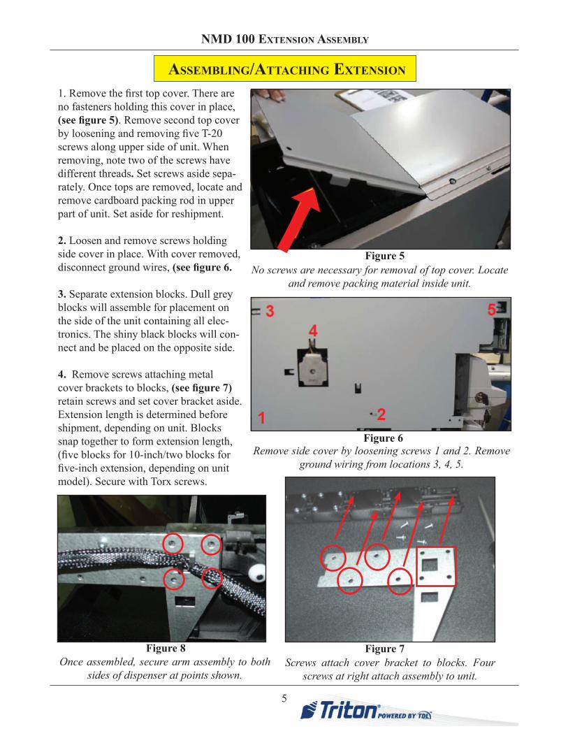
1. Remove the first top cover. There are no fasteners holding this cover in place, (see figure 5). Remove second top cover by loosening and removing five T-20 screws along upper side of unit. When removing, note two of the screws have different threads. Set screws aside sepa-rately. Once tops are removed, locate and remove cardboard packing rod in upper part of unit. Set aside for reshipment.
2. Loosen and remove screws holding side cover in place. With cover removed, disconnect ground wires, (see figure 6.
3. Separate extension blocks. Dull grey blocks will assemble for placement on the side of the unit containing all elec-tronics. The shiny black blocks will con-nect and be placed on the opposite side.
4. Remove screws attaching metal cover brackets to blocks, (see figure 7)retain screws and set cover bracket aside. Extension length is determined before shipment, depending on unit. Blocks snap together to form extension length, (five blocks for 10-inch/two blocks for five-inch extension, depending on unit model). Secure with Torx screws.
Screws attach cover bracket to blocks. Four screws at right attach assembly to unit.
Remove side cover by loosening screws 1 and 2. Remove ground wiring from locations 3, 4, 5.
Figure 6
Figure 7
Figure 5No screws are necessary for removal of top cover. Locate
and remove packing material inside unit.
AssEMbliNg/AttACHiNg ExtENsioN
Once assembled, secure arm assembly to both sides of dispenser at points shown.
Figure 8
6
NMD 100 ExtENsioN AssEMbly
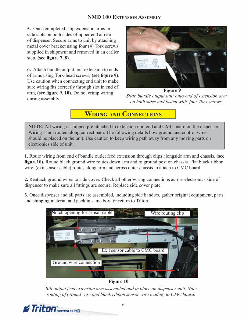
1. Route wiring from end of bundle outlet feed extension through clips alongside arm and chassis, (see figure10). Round black ground wire routes down arm and to ground post on chassis. Flat black ribbon wire, (exit sensor cable) routes along arm and across outer chassis to attach to CMC board.
2. Reattach ground wires to side cover. Check all other wiring connections across electronics side of dispenser to make sure all fittings are secure. Replace side cover plate.
Slide bundle output unit onto end of extension arm on both sides and fasten with four Torx screws.
3. Once dispenser and all parts are assembled, including side handles, gather original equipment, parts and shipping material and pack in same box for return to Triton.
NOTE: All wiring is shipped pre-attached to extension unit end and CMC board on the dispenser. Wiring is not routed along correct path. The following details how ground and control wires should be placed on the unit. Use caution to keep wiring path away from any moving parts on electronics side of unit.
Bill output feed extension arm assembled and in place on dispenser unit. Note routing of ground wire and black ribbon sensor wire leading to CMC board.
Figure 10
Ground wire connection
Exit sensor cable to CMC board
Notch opening for sensor cable Wire routing clip
WiriNg AND CoNNECtioNs
Figure 9
5. Once completed, slip extension arms in-side slots on both sides of upper end at rear of dispenser. Secure arms to unit by attaching metal cover bracket using four (4) Torx screws supplied in shipment and removed in an earlier step, (see figure 7, 8).
6. Attach bundle output unit extension to ends of arms using Torx-head screws, (see figure 9). Use caution when connecting end unit to make sure wiring fits correctly through slot in end of arm, (see figure 9, 10). Do not crimp wiring during assembly.