Embed Size (px)
Citation preview
NMI M 10-2 Meters Intended for the Metering of Water in Full Flowing Pipes
Part 2: Test Methods
ii
© Commonwealth of Australia 2009
First edition — August 2009 Second edition — July 2010 Second edition, first revision — March 2011
National Measurement Institute Bradfield Road, Lindfield, NSW 2070 PO Box 264, Lindfield, NSW 2070
T (61 2) 8467 3600 F (61 2) 8467 3610 W www.measurement.gov.au
AMENDMENTS
Erratum Date Page Location Details of change
1 21/03/2011 52
and 54 Tables C.1, E.1 and E.2
Correction to indicate how a ‘family’ of meters is identified. Annexes C and E now align closely with a similar Annex in NMI R 49-2.

iii
CONTENTS Preface ....................................................................................................................................................................................... iv
1. Scope .................................................................................................................................................................................... 1
2. Terminology ......................................................................................................................................................................... 1
3. Reference Conditions ........................................................................................................................................................... 1 3.1 General........................................................................................................................................................................ 1 3.2 Flowate and Power Supply.......................................................................................................................................... 1 3.3 Temperature ................................................................................................................................................................ 1 3.4 Humidity and Pressure ................................................................................................................................................ 1
4. Calculation of error .............................................................................................................................................................. 1
5. External Examination ........................................................................................................................................................... 2 5.1 Object of Examination ................................................................................................................................................ 2 5.2 Preparation .................................................................................................................................................................. 2 5.3 Examination Procedures.............................................................................................................................................. 2
6. Performance Tests ................................................................................................................................................................ 7 6.1 Requirements Common to all Tests ............................................................................................................................ 7 6.2 Static Pressure Test ..................................................................................................................................................... 7 6.3 Determination of Intrinsic Errors of Indication and the Effects of Meter Orientation ................................................ 8 6.4 Absence of Flow Test................................................................................................................................................ 13 6.5 Water Pressure Test................................................................................................................................................... 13 6.6 Flow Reversal Test.................................................................................................................................................... 14 6.7 Pressure Loss Test..................................................................................................................................................... 15 6.8 Flow Disturbance Tests............................................................................................................................................. 18 6.9 Endurance Tests ........................................................................................................................................................ 18 6.10 Water Quality Disturbance Test ................................................................................................................................ 19 6.11 Meters Used in Open Channel Emplacements .......................................................................................................... 22 6.12 Installation Tests ....................................................................................................................................................... 27 6.13 Test for Cartridge Meters and Meters with Interchangeable Inserts.......................................................................... 28 6.14 Maintenance Tests..................................................................................................................................................... 28
7. Performance Tests for Electronic Meters and Mechanical Meters Fitted with Electronic Devices.................................... 30 7.1 General Requirements ............................................................................................................................................... 30 7.2 Dry Heat (Non-condensing) ...................................................................................................................................... 33 7.3 Cold........................................................................................................................................................................... 33 7.4 Damp Heat, Cyclic (Condensing) ............................................................................................................................. 34 7.5 Power Voltage Variation........................................................................................................................................... 34 7.6 Vibration (Random) .................................................................................................................................................. 36 7.7 Mechanical Shock ..................................................................................................................................................... 36 7.8 Short-time Power Reductions.................................................................................................................................... 37 7.9 Bursts ........................................................................................................................................................................ 38 7.10 Electrostatic Discharge.............................................................................................................................................. 39 7.11 Electromagnetic Susceptibility.................................................................................................................................. 40 7.12 Water......................................................................................................................................................................... 41 7.13 Dust ........................................................................................................................................................................... 42
8. Test Program for Pattern Approval..................................................................................................................................... 42 8.1 Number of Samples Required ................................................................................................................................... 42 8.2 Tests Applicable to all Meters................................................................................................................................... 43 8.3 Tests Applicable to Electronic Meters, Mechanical Meters Fitted with Electronic Devices
and their Separable Parts ........................................................................................................................................... 43 8.4 Pattern Approval of Separable Parts ......................................................................................................................... 43 8.5 Families of Meters..................................................................................................................................................... 44
9. Tests for Initial Verification ............................................................................................................................................... 44 9.1 Water Meter .............................................................................................................................................................. 44 9.2 Separable Parts.......................................................................................................................................................... 45
10. Presentation of Results ....................................................................................................................................................... 45 10.1 Object of Reports ...................................................................................................................................................... 45 10.2 Identification and Test Data to be Included in Records ............................................................................................ 45
Annex A. Calculating the Relative Error of Indication (Mandatory)........................................................................................ 47
Annex B. Flow Disturbance Tests (Mandatory) ....................................................................................................................... 49
Annex C. Pattern Evaluation of a Family of Meters (Mandatory)............................................................................................ 52
Annex D. Pressure Loss Test: Pressure Tappings, Hole and Slot Details (Informative) .......................................................... 53
Annex E. Guidance on Tests and Sample Sizes for Pattern Approval ...................................................................................... 54
Bibliography ............................................................................................................................................................................. 56

iv
PREFACE
NMI M 10-2 is based on NMI R 49-2. Water Meters Intended for the Metering of Cold Potable Water and Hot Water. Part 2: Test Methods (which in turn is based on OIML R 49-2:2006).
Some meters may have been previously tested and approved in accordance with NMI R 49 or OIML R 49 either in Australia or overseas.
In Australia, meters may be pattern approved against both NMI R 49 and NMI M 10. The pattern approval certificate will indicate against which standard the meter has been approved.
Some test results performed in accordance with NMI R 49 or OIML R 49, due to the similarity of the methodology, will be accepted as part of a pattern approval application for NMI M 10.
All tests performed in accordance with NMI R 49 or OIML R 49 will be recognised as being performed with potable water. Further testing with non-potable water may be required.
As well as minor editorial corrections, this second edition of NMI 10-2 differs from the first edition in that it reflects the changes between the second and third editions of NMI M 10-1. Note in particular changes to the following clauses: clauses 6.1.3 and 7.1.6 on meter scanning rates have been added; clause 6.4 on absence of flow test has been added; clause 6.9 on endurance testing requirements has been amended; clause 6.10 on water quality disturbance test has been added; clause 6.11.6.3 on disturbance testing requirements has been amended; clause 6.13 on cartridge meters and meters with interchangeable inserts has been added; clause 7.9 on data and communications ports in test procedure has been amended; Annex C, the explanation of meter families has been expanded; and Annex E has been added to give guidance on tests performed and sample sizes.

03/2011 NMI M 10-2 1
1. SCOPE
NMI M 10-2 specifies test methods for the pattern approval and verification of water meters intended for the metering of water in full flowing pipes. Meters approved against this document are designated as accuracy class 2.5 water meters. In addition, this document outlines the testing requirements for closed conduit meters that are intended to meter water in open channel emplacements (see 6.11).
The corresponding parts 1 and 3 of this document are: NMI M 10-1 Metrological and
Technical Requirements [1]; and 60
NMI M 10-3 Test Report Format [2].
2. TERMINOLOGY
The terms and definitions in NMI M 10-1 [1] shall apply.
Some of the definitions used in this document conform to terminology used in IEC 60068-1 [3] and are adopted where necessary.
3. REFERENCE CONDITIONS
3.1 General
All applicable influence quantities, except for the influence quantity being tested, shall be held at the following values during pattern approval tests on a meter. However, for influence factors and disturbances for electronic meters, it is permissible to use the reference conditions defined in the applicable IEC standard. NMI can provide guidance on any issues related to permissible reference conditions.
3.2 Flowate and Power Supply
Flowrate: 0.7 (Q1 + Q3) 0.03 (Q1 + Q3)
Module measurement parameter: 0.7 (min + max) ± 0.03 (min + max) where min and max are the minimum and maximum boundaries of the range over which the module is claimed to be within accuracy limits
Power supply voltage (mains AC): nominal voltage (Unom) 5%
Power supply frequency: nominal frequency (fnom) 2%
Power supply voltage (battery): a voltage V in the range Umin V Umax
3.3 Temperature
The ambient and working temperature ranges given below allow for seasonal and climatic variations. However during all performance testing the ambient and working temperature shall not vary by more than ±5°C over the period of the testing.
Working temperature: 20 10°C Ambient temperature: 20 10°C
3.4 Humidity and Pressure
The values given below for ambient relative humidity and atmospheric pressure are the recommended ranges over which pattern approval testing should be conducted. These conditions shall be recorded appropriately.
Ambient relative humidity: 60 15% Ambient atmospheric pressure: 86 to 106 kPa
4. CALCULATION OF ERROR
Equations, symbols and their units, concerning the calculation of the error of indication of a meter used in this document, are given in Annex A.
03/2011 NMI M 10-2 2
5. EXTERNAL EXAMINATION
During the external examination, all relevant values, dimensions and observations shall be recorded. For presentation of the results of pattern examinations see 10.
5.1 Object of Examination
To verify that the meter meets the requirements of NMI M 10-1 with respect to the design of the indicating device, the marking of the meter and the application of protection devices.
5.2 Preparation
Linear measurements that have to be taken from the meter shall be made using traceable, calibrated measuring devices.
The actual or apparent dimensions of the scales of the indicating device shall be taken without removing the meter lens or disassembling the meter.
Note: A travelling microscope (cathetometer) may be used to measure the width, spacing and height of the scale divisions and the height of numerals.
5.3 Examination Procedures
Each of the following aspects of the meter design shall be examined on at least one meter from the sample.
Either the same meter sample may be used for all the external examinations or different meters from the samples submitted may be used for some of the examinations.
5.3.1 Marks and Inscriptions (NMI M 10-1, 5.8)
1. Verify that the meter is clearly and indelibly marked with the following information (either grouped or distributed on the casing, the indicating device dial, an identification plate or on the meter cover if it is not detachable), or recorded in the meter’s memory: (a) unit of measurement : megalitre
(ML), cubic metre (m3) or kilolitre (kL);
(b) numerical value of Q3 and the ratio Q3/Q1;
(c) pattern approval mark; (d) name or trade mark of the
manufacturer; (e) serial number (as near as possible
to the indicating device); (f) year of manufacture (optional); (g) direction of flow (shown on both
sides of the body; or on one side only provided the direction of flow arrow is easily visible under all circumstances);
(h) maximum admissible pressure;
(i) letter V or H, if the meter can only be operated in the vertical or horizontal position;
(j) maximum pressure loss;
(k) for insertion or strap-on meters, the pipe bore diameter and outside diameter in which the meter is required to operate;
for meters with electronic devices, the following additional inscriptions where appropriate:
(l) for an external power supply: the voltage and frequency;
(m) for a replaceable battery: the latest date that the battery is to be replaced; alternatively provision shall be made to allow this date to be recorded in the memory of the meter upon replacement of the battery and installation of the meter by a certified person;
(n) for a non-replaceable battery: the latest date by which the meter is to be replaced; alternatively provision shall be made to allow this date to be recorded in the memory of the meter upon installation by a certified person; and
(o) the IP rating of the meter and its constituent parts.
2. Complete the test report (NMI M 10-3, section 4.1, 5.8).

03/2011 NMI M 10-2 3
5.3.2 Indicating Device or Display
5.3.2.1 General Requirements (NMI M 10-1, 5.9.1)
1. Verify that the indicating device provides an easily read, reliable and unambiguous visual indication of the indicated volume.
2. Verify that the indicating device includes visual means for testing and calibration.
3. If the indicating device includes additional elements for testing and calibration by other methods, e.g. for automatic testing and calibration, record the type(s) of device.
4. If the indicating device displays other parameters such as instantaneous or average flowrate, record the parameters.
5. Complete the test report (NMI M 10-3, section 4.1, 5.9.1).
5.3.2.2 Unit of Measurement, Symbol and its Placement (NMI M 10-1, 5.9.1.1)
1. Verify that the indicated volume of water is expressed in megalitres, cubic metres or kilolitres.
2. Verify that the symbol ML, m3 or kL appears on the dial or immediately adjacent to the numbered display.
3. Complete the test report (NMI M 10-3, section 4.1, 5.9.1.1).
5.3.2.3 Indicating Range (NMI M 10-1, 5.9.1.2)
1. Verify that the indicating device is able to record the indicated volume in megalitres, cubic metres or kilolitres corresponding to at least 200 days of operation at the permanent flowrate Q3, without passing through zero. Examples of compliance are shown in Table 1 and Table 2.
Table 1. Volumetric (ML) indicating range
Q3 (ML/d) Indicating range (ML) (minimum values)
Q3 50 9 999
50 < Q3 500 99 999
500 < Q3 5 000 999 999
Table 2. Volumetric (m3 or kL) indicating range
Q3 (L/s) Indicating range (m3 or kL) (minimum values)
Q3 0.5 9 999 0.5 < Q3 5 99 999
5 < Q3 50 999 999
2. Calculate the indicated volume (Vi) corresponding to 200 days of operation.
If Q3 is the numerical value of the permanent flowrate Q3: in ML/d, Vi = Q3 × 200 ML; in L/s, Vi = Q3 × 17 280 m3 or kL
where Q3 is the numerical value of the permanent flowrate Q3 in ML/d (or L/s).
3. Complete the test report (NMI M 10-3, section 4.1, 5.9.1.2).
5.3.2.4 Colour Coding for Indicating Devices (NMI M 10-1, 5.9.1.3)
1. Verify that either:
the colour black is used to indicate the megalitre, cubic metre or kilolitre and its multiples; the colour red is used to indicate sub-multiples of a megalitre, cubic metre or kilolitre; and the colours are applied either to the pointers, indexes, numbers, wheels discs, dials or aperture frames; or
other means of indicating the megalitre, cubic metre or kilolitre are used in which there is no ambiguity in distinguishing between the primary indication and alternative displays, e.g. sub-multiples for verification and testing.
2. Complete the test report (NMI M 10-3, section 4.1, 5.9.1.3).

03/2011 NMI M 10-2 4
5.3.2.5 Types of Indicating Device
5.3.2.5.1 Type 1 – Analogue Device (NMI M 10-1, 5.9.2.1)
1. If a type 1 indicating device has been used verify that volume is indicated by either:
continuous movement of one or more pointers moving relative to graduated scales; or
continuous movement of one or more circular scales or drums each passing an index.
2. Verify that the value expressed in megalitres, cubic metres or kilolitres for each scale division is of the form 10n, where n is a positive or a negative whole number or zero, thereby establishing a system of consecutive decades.
3. Verify that each scale is either graduated in values expressed in megalitres, cubic metres or kilolitres or accompanied by a multiplying factor (× 0.001; × 0.01; × 1; × 10; × 100; × 1000 etc).
4. Verify that rotational movements of the pointers or circular scales are clockwise.
5. Verify that linear movement of pointers or scales is from left to right.
6. Verify that movement of numbered roller indicators is upwards.
7. Complete the test report (NMI M 10-3, section 4.1, 5.9.2.1).
5.3.2.5.2 Type 2 – Digital Device (NMI M 10-1, 5.9.2.2)
1. Verify that the indicated volume is given by a line of digits, appearing in one or more apertures.
2. Verify that the advance of one digit is completed while the digit of the next immediately lower decade changes from 9 to 0.
3. For non-electronic devices:
verify that the movement of numbered roller indicators (drums) is upwards; and
if the lowest value decade has a continuous movement, verify that the aperture is large enough to permit a digit to be read without ambiguity.
4. For electronic devices:
note whether the electronic display is either permanent or non-permanent;
where a non-permanent display is used, verify that the volume is able to be displayed at any time for at least 10 s;
verify that the electronic device includes a feature that enables the correct operation of the display to be checked (e.g. by successive display of the various characters); each step of the sequence shall last at least 1 s.
5. Verify that the actual or apparent height of the digits is at least 4 mm.
6. Complete the test report (NMI M 10-3, section 4.1, 5.9.2.2).
5.3.2.5.3 Type 3 – Combination of Analogue and Digital Devices (NMI M 10-1, 5.9.2.3)
1. If the indicating device is a combination of types 1 and 2 devices, verify that the respective requirements of each apply (5.3.2.5.1 and 5.3.2.5.2).
2. Complete the test report (NMI M 10-3, section 4.1, 5.9.2.3).
5.3.2.6 Verification Devices – First Element of an Indicating Device – Verification Interval
5.3.2.6.1 General Requirements (NMI M 10-1, 5.9.4.1)
1. Verify that the indicating device has the means for visual, non-ambiguous verification testing and calibration.
2. Note whether the visual verification display has a continuous or a discontinuous movement.
03/2011 NMI M 10-2 5
3. Note whether, in addition to the visual verification display, the indicating device includes provisions for rapid testing by the inclusion of complementary elements (e.g. star wheels or discs) providing signals through externally attached sensors. Note the relationship, stated by the manufacturer, between the visual indication of volume and the signals emitted by these complementary devices.
4. Complete the test report (NMI M 10-3, section 4.1, 5.9.4.1).
5.3.2.6.2 Value of the Verification Scale Interval (NMI M 10-1, 5.9.4.2)
1. Verify that the value of the verification scale interval, expressed in megalitres, kilolitres or cubic metres, is of the form 1 × 10n, or 2 × 10n, or 5 × 10n, where n is a positive or negative whole number or zero.
2. For analogue and digital indicating devices with continuous movement of the first element, verify that the verification scale interval is formed from the division into 2, 5 or 10 equal parts of the interval between two consecutive digits of the first element.
3. For analogue and digital indicating devices with continuous movement of the first element, verify that numbering is not applied to the divisions between consecutive digits of the first element.
4. For digital indicating devices, including electronic devices, with discontinuous movement of the first element, the verification scale interval is the interval between two consecutive digits or incremental movements of the first element.
5. Complete the test report (NMI M 10-3, section 4.1, 5.9.4.2).
5.3.2.6.3 Form of the Verification Scale (NMI M 10-1, 5.9.4.3)
1. If the indicating device has continuous movement of the first element, check
that the apparent scale spacing is not less than 1 mm and not more than 5 mm.
Note: This does not apply to devices with discontinuous movement.
2. Verify that the scale consists of either: lines of equal thickness not exceeding
one-quarter of the scale spacing and differing only in length; or
contrasting bands of a constant width equal to the scale spacing.
3. Verify that the apparent width of the pointer at its tip does not exceed one-quarter of the scale spacing.
4. Verify that the apparent width of the pointer at its tip does not exceed 0.5 mm.
5. Complete the test report (NMI M 10-3, section 4.1, 5.9.4.3).
5.3.2.6.4 Resolution of the Indicating Device (NMI M 10-1, 5.9.4.4)
1. Note the value of the verification scale interval, V ML or m3 or kL.
2. Calculate the actual volume Va passed during 1 h 30 min at the minimum flowrate, Q1: Va = Q1 × 1.5 ML or m3or kL
3. Calculate the resolution error of the indicating device, r.
4. For continuous movement of the first element: r = 100 × (½ V + ½ V)/ Va% = 100 × V/ Va%
5. For discontinuous movement of the first element: r = 100 × (V + V)/ Va% = 100 × 2V/ Va%
6. Verify that the verification scale interval is small enough to ensure that the resolution error, r, of the indicating device does not exceed 0.5% of the actual volume required during 1 h 30 min at the minimum flow rate, Q1: r 0.5%
7. Complete the test report (NMI M 10-3, section 4.1, 5.9.4.4).
03/2011 NMI M 10-2 6
Notes:
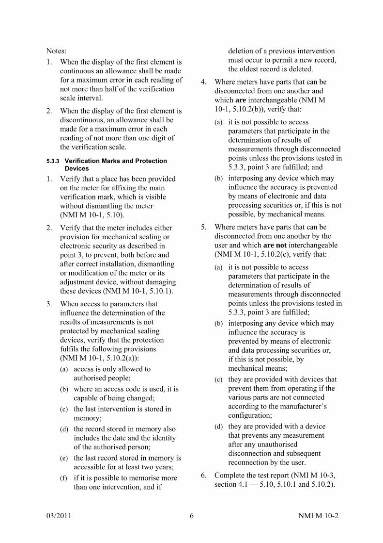
1. When the display of the first element is continuous an allowance shall be made for a maximum error in each reading of not more than half of the verification scale interval.
2. When the display of the first element is discontinuous, an allowance shall be made for a maximum error in each reading of not more than one digit of the verification scale.
5.3.3 Verification Marks and Protection Devices
1. Verify that a place has been provided on the meter for affixing the main verification mark, which is visible without dismantling the meter (NMI M 10-1, 5.10).
2. Verify that the meter includes either provision for mechanical sealing or electronic security as described in point 3, to prevent, both before and after correct installation, dismantling or modification of the meter or its adjustment device, without damaging these devices (NMI M 10-1, 5.10.1).
3. When access to parameters that influence the determination of the results of measurements is not protected by mechanical sealing devices, verify that the protection fulfils the following provisions (NMI M 10-1, 5.10.2(a)):
(a) access is only allowed to authorised people;
(b) where an access code is used, it is capable of being changed;
(c) the last intervention is stored in memory;
(d) the record stored in memory also includes the date and the identity of the authorised person;
(e) the last record stored in memory is accessible for at least two years;
(f) if it is possible to memorise more than one intervention, and if
deletion of a previous intervention must occur to permit a new record, the oldest record is deleted.
4. Where meters have parts that can be disconnected from one another and which are interchangeable (NMI M 10-1, 5.10.2(b)), verify that:
(a) it is not possible to access parameters that participate in the determination of results of measurements through disconnected points unless the provisions tested in 5.3.3, point 3 are fulfilled; and
(b) interposing any device which may influence the accuracy is prevented by means of electronic and data processing securities or, if this is not possible, by mechanical means.
5. Where meters have parts that can be disconnected from one another by the user and which are not interchangeable (NMI M 10-1, 5.10.2(c), verify that:
(a) it is not possible to access parameters that participate in the determination of results of measurements through disconnected points unless the provisions tested in 5.3.3, point 3 are fulfilled;
(b) interposing any device which may influence the accuracy is prevented by means of electronic and data processing securities or, if this is not possible, by mechanical means;
(c) they are provided with devices that prevent them from operating if the various parts are not connected according to the manufacturer’s configuration;
(d) they are provided with a device that prevents any measurement after any unauthorised disconnection and subsequent reconnection by the user.
6. Complete the test report (NMI M 10-3, section 4.1 — 5.10, 5.10.1 and 5.10.2).
03/2011 NMI M 10-2 7
6. PERFORMANCE TESTS
During the performance tests, all relevant values, dimensions and observations shall be recorded. For presentation of the results of pattern examinations see 10.
6.1 Requirements Common to all Tests
6.1.1 Water Quality
Tests shall be carried out using water. The manufacturer and the approving authority shall agree upon a desired level (and range) of water quality before the commencement of testing. Filtering systems may be used to achieve the desired level of water quality.
If the EUT employs electromagnetic induction as a measuring principle then the conductivity of the water used should be within the operational range of conductivity specified by the meter manufacturer.
At the time of each test the water quality shall be measured and recorded.
The pattern approval certificate will indicate the measures of water quality taken during pattern approval testing as well as the results of testing performed in accordance with 6.10.
Note: If water is being recycled, measures shall be taken to prevent residual water from becoming harmful to human beings.
6.1.2 General Rules Concerning Test Installation and Location
6.1.2.1 Freedom from Spurious Influences
Test rigs shall be so designed, constructed and used, that the performance of the rig itself shall not contribute significantly to the test error. To this end, high standards of rig maintenance and adequate supports and fittings are necessary to prevent vibration of the meter, the test rig and its accessories.
The test rig environment shall be such that the reference conditions of the test are met (see 3).
It shall be possible to carry out test readings rapidly and easily.
As part of the validation process, periodic intercomparisons between test rigs shall be carried out.
6.1.2.2 Group Testing
Meters are tested either individually or in groups. In the latter case the individual characteristics of the meters shall be precisely determined. Interaction between meters, and between meters and test rigs, shall be eliminated.
When meters are tested in series, the pressure at the exit of each meter shall be sufficient to prevent cavitation.
6.1.2.3 Location
The environment chosen for tests shall be free from disturbing influences, e.g. extreme ambient temperature, vibration.
6.1.3 Meter Scanning Rates
The manufacturer shall be able to nominate the scanning rate of the meter at which flow testing will be performed. This scanning rate shall be within those specified in manuals or other such documentation concerning the meter. This scanning rate will be included in the pattern approval certificate.
6.2 Static Pressure Test
Refer to NMI M 10-1, 6.2.1.
6.2.1 Object of Test
To verify that the meter can withstand the specified hydraulic test pressure for the specified time without leakage or damage.
6.2.2 Preparation
1. Install the meters in the test rig either singly or in groups.
2. Bleed the test rig pipework and the meters of air.
3. Ensure that the test rig is free from leaks.
4. Ensure that the supply pressure is free from pressure pulsations.
03/2011 NMI M 10-2 8
6.2.3 Test Procedure
1. Increase the hydraulic pressure to 1.6 times the maximum admissible pressure of the meter and hold it for 15 min.
2. Examine the meters for physical damage, for external leaks and for leaks into the indicating device.
3. Increase the hydraulic pressure to twice the maximum admissible pressure and hold this pressure level for 1 min.
4. Examine the meters for physical damage, for external leaks and for leaks into the indicating device.
5. Complete the test report (NMI M 10-3, section 5.1).
Additional requirements:
(a) Increase and decrease the pressure gradually without pressure surges.
(b) Apply only the reference temperatures for this test.
(c) For an insertion meter, attach the meter to a piece of pipe capable of meeting these pressure test requirements and test as per the above procedure.
6.2.4 Acceptance Criteria
There shall be no leakage from the meter, leakage into the indicating device or physical damage, resulting from any of the pressure tests.
6.3 Determination of Intrinsic Errors of Indication and the Effects of Meter Orientation
Refer to NMI M 10-1, 6.2.2.
6.3.1 Object of Test
To determine the intrinsic errors of indication of the meter and the effects of meter orientation on the error of indication.
6.3.2 Preparation
6.3.2.1 Description of the Test Rig
Two methods of determining the errors of indication of a meter are described here,
however other methods may be used, provided the requirements of 6.3.2.2.6.1 are met.
1. One method is the collection method, in which the quantity of water passed through the meter is collected in one or more collecting vessels and the quantity determined volumetrically or by weighing. Errors of indication are then calculated by comparing the volume indications given by the meter operating at reference conditions against the calibrated reference device.
2. Another method consists of installing at least one calibrated reference meter in the test rig and passing the quantity of water through the EUT and the reference meter(s); the water may be re-circulated through the system. Errors of indication are then calculated by comparing the volume indications given by the meter operating at reference conditions against the calibrated reference meter.
For the purpose of these tests, a meter should be tested without its temporary supplementary devices attached (if any).
The test rig consists, typically, of:
(a) a water supply (non-pressurised tank, pressurised tank, pump etc);
(b) pipework;
(c) a calibrated reference device (calibrated volumetric tank, weighing system, reference meter etc);
(d) means for measuring the time of the test;
(e) devices for automating the tests (if required);
(f) means for measuring water temperature;
(g) means for measuring water pressure.
6.3.2.2 Pipework
6.3.2.2.1 Description
Pipework shall include:
(a) a test section in which the meter(s) is (are) placed;

03/2011 NMI M 10-2 9
(b) means for establishing the desired flowrate;
(c) one or two isolating devices;
(d) means for determining the flowrate;
and if necessary:
(e) means for checking that the pipework is filled to a datum level before and after each test;
(f) one or more air bleeds;
(g) a non-return device;
(h) an air separator;
(i) a filter (if required).
During the test, flow leakage, flow input and flow drainage shall not be permitted either between the meter(s) and the reference device or from the reference device.
The pipework shall be such that in the upper, internal part of the meter, a positive pressure exists, even at zero flowrate.
6.3.2.2.2 Test Section
The test section shall include, in addition to the meter(s):
(a) one or more pressure tappings for the measurement of pressure, of which one pressure tapping is situated upstream of, and close to, the (first) meter;
(b) means for measuring the temperature of the water close to the entry of the (first) meter.
The presence of any pipe components or devices placed in or near the measuring section shall not cause cavitation or flow disturbances capable of altering the performance of the meters or causing errors of indication.
6.3.2.2.3 Precautions to be Taken
1. Check that the operation of the test rig is such that, during a test, the actual volume of water that flows through the meter(s) is equal to that measured by the reference device.
2. Check that the pipe (e.g. the swan-neck in the outlet pipe) is filled to the same
datum level at the beginning and at the end of the test.
3. Bleed all air from the interconnecting pipework and the meter(s). The manufacturer may recommend a procedure that ensures that all air is bled from the meter.
4. Take all precautions necessary to avoid the effects of vibration and shock.
5. Check that the lead-in/lead-out pipe has the same internal diameter as the meter. If an exact match cannot be achieved, it is acceptable to use piping that has a slightly larger internal diameter than the meter. However, any difference in the internal diameter should be kept to an absolute minimum.
6.3.2.2.4 Special Arrangements for the Installation of Meters
6.3.2.2.4.1 Avoidance of Erroneous Measurements
The recommendations in 6.3.2.2.4.2 to 6.3.2.2.4.5 address the most frequent causes of erroneous measurements and the necessary precautions for the installation of meters on the test rig, and are intended to achieve a test installation in which:
(a) the hydrodynamic flow characteristics cause no discernible difference to the meter functioning when compared with hydrodynamic flow characteristics which are undisturbed;
(b) the overall error of the method employed does not exceed the stipulated value (see 6.3.2.2.6.1).
6.3.2.2.4.2 Need for Straight Lengths of Pipe or a Flow Straightener
The accuracy of non-volumetric meters can be affected by upstream disturbance caused, e.g. by the presence of bends, tees, valves or pumps.
It is important to eliminate any such disturbances caused by the configuration of the test rig itself in order to ensure the repeatability and inter-laboratory
03/2011 NMI M 10-2 10
comparison of test results. In order to counteract these disturbances:
(a) the meter shall be installed in accordance with the manufacturer’s instructions;
(b) the connecting pipework shall have an internal diameter matched to the relevant meter connection;
(c) if necessary, a flow straightener shall be installed upstream of the straight pipe length and the standard disturbances defined in 6.8.
6.3.2.2.4.3 Common Causes of Flow Disturbance
A flow can be subject to two types of disturbance: velocity-profile distortion and swirl, both of which may affect the errors of indication of a meter.
Velocity-profile distortion is typically caused by an obstruction partially blocking the pipe, for instance the presence of a partly closed valve or a misaligned flange joint. This can easily be eliminated by careful application of installation procedures.
Swirl can be caused either by two or more bends in different planes or a single bend in combination with a reducer or partially closed valve. This effect can be controlled either by ensuring an adequate length of straight pipe upstream of the meter, or by installing a flow straightening device, or by a combination of the two. However, where possible, these types of pipework configurations should be avoided.
6.3.2.2.4.4 Volumetric Meters
Volumetric meters (that is, involving measuring chambers with mobile walls) such as oscillating piston or nutating disc meters, are considered insensitive to upstream installation conditions; hence no special conditions are required.
6.3.2.2.4.5 Meters Employing Electromagnetic Induction
Meters employing electromagnetic induction as a measuring principle may be
affected by the conductivity of the test water.
The conductivity of the water used for testing this type of meter should be within the operational range of conductivity specified by the meter manufacturer.
6.3.2.2.4.6 Other Measuring Principles
Other types of meter may require flow conditioning when measuring the errors of indication and in such cases the manufacturer’s recommended installation requirements shall be followed (see 6.8).
These installation requirements should be reported in the pattern approval certificate for the meter.
6.3.2.2.5 Errors of Test Commencement and Termination
Adequate precautions shall be taken to reduce the uncertainties resulting from operation of test rig components during the test.
Details of the precautions to be taken are given in 6.3.2.2.5.1 and 6.3.2.2.5.2 for two cases encountered in the collection method.
If testing is being conducted using a reference meter, readings can easily be taken using a variation of the flying-start-and-finish method (see 6.3.2.2.5.2). However it must be ensured that the reference meter and EUT can be synchronised such that they both accurately register the beginning and end of each test. This could be done retrospectively by matching up the time stamps of their pulse outputs once the desired flowrate had been established.
6.3.2.2.5.1 Tests with Readings taken with the Meter at Rest
This method is generally known as the standing-start-and-finish method.
Flow is established by fully opening a valve, preferably situated downstream of the meter, and it is stopped by closure of this valve. The meter is read when the registration is stationary.
03/2011 NMI M 10-2 11
Time is measured between the beginning of the movement of the valve at opening and at the end of closure.
Whilst flow is beginning (and during the period of running at the specified constant flowrate) the error of indication of the meter varies as a function of the changes in flowrate (the error curve).
Whilst the flow is being stopped, the combination of the inertia of the moving parts of the meter and the rotational movement of the water inside the meter may cause an appreciable error to be introduced in certain types of meter and for certain test flowrates.
It has not been possible, in this case, to determine a simple empirical rule which lays down conditions so that this error may always be negligible.
In case of doubt, it is advisable: (a) to increase the volume and duration of
the test; (b) to compare the results with those
obtained by one or more other methods, and in particular the method described in 6.3.2.2.5.2, which eliminates the causes of uncertainty given above.
For some types of electronic meters with pulse outputs that are used for testing, the response of the meter to changes in flowrate may be such that valid pulses are emitted after closure of the valve. In this case means shall be provided to count these additional pulses.
Where pulse outputs are used for testing meters, it shall be checked that the volume indicated by the pulse count corresponds to the volume displayed on the indicating device.
6.3.2.2.5.2 Tests with Readings taken under Stable Flow Conditions and Diversion of Flow
This method is generally known as the flying-start-and-finish method.
The measurement is carried out when flow conditions have stabilised.
A switch diverts the flow into a calibrated vessel at the beginning of the measurement and diverts it away at the end.
The meter is read whilst in motion.
The reading of the meter is synchronised with the movement of the flow switch.
The volume collected in the vessel is the actual volume passed.
The uncertainty introduced into the volume may be considered negligible if the times of motion of the flow switch in each direction are identical within 5% and if this time is less than 1/50 of the total time of the test.
6.3.2.2.6 Calibrated Reference Device
6.3.2.2.6.1 Overall Uncertainty of the Value of Measured Actual Volume
When a test is conducted, the expanded uncertainty of the value of measured actual volume shall not exceed one-fifth of the MPE for pattern approval and one-third of the MPE for initial verification.
The estimated uncertainty shall be made according to the Guide to the Expression of Uncertainty in Measurement [4] with a coverage factor, k = 2.
6.3.2.2.6.2 Minimum Volume of the Calibrated Reference Device
The minimum volume permitted depends on requirements determined by the test start and end effects (timing error), and the design of the indicating device (value of the verification scale interval).
6.3.2.2.6.3 Cyclic Distortion of the Meter
The effects of a possible cyclic distortion on the reading of the meter (visual or automatic) shall be negligible.
6.3.2.2.7 Major Factors Affecting the Measurement of Errors of Indication
6.3.2.2.7.1 General
Variations in the pressure, flowrate and temperature in the test rig, and uncertainties in the precision of measurement of these physical quantities, are the principal factors affecting the measurement of the errors of indication of a meter.
03/2011 NMI M 10-2 12
6.3.2.2.7.2 Supply Pressure
The supply pressure shall be maintained at a constant value throughout the test at the chosen flowrate.
When testing meters which are designated Q3 4 L/s, at test flowrates 0.1 Q3, constancy of pressure at the inlet of the meter (or at the inlet of the first meter of a group being tested) is achieved if the test rig is supplied through a pipe from a constant head tank. This ensures an undisturbed flow.
Any other methods of supply shown not to cause pressure pulsations exceeding those of a constant head tank may be used, e.g. a pressurised tank.
For all other tests, the pressure upstream of the meter shall not vary by more than 10%.
The maximum uncertainty (k = 2) in the measurement of pressure shall be 5% of the measured value.
Pressure at the entrance to the meter shall not exceed the maximum admissible pressure for the meter.
6.3.2.2.7.3 Flowrate
A constant flowrate shall be maintained throughout the test.
The relative variation in the flowrate during each test (not including starting and stopping) shall not exceed ±5.0% from Q1 (inclusive) to Q4.
The flowrate value is the actual volume passed during the test divided by the time.
This flowrate variation condition is acceptable if the relative pressure variation (in flow to free air) or the relative variation of pressure loss (in closed circuits) does not exceed ±10% from Q1 (inclusive) to Q4.
6.3.2.2.7.4 Temperature
During a test, the temperature of the water shall not change by more than 5ºC.
The maximum uncertainty (k = 2) in the measurement of temperature shall not exceed 1ºC.
6.3.2.2.7.5 Orientation of Meter(s)
1. If the meters are marked ‘H’, mount the connecting pipework with the flow axis in the horizontal plane during the test.
2. If the meters are marked ‘V’, mount the connecting pipework with the flow axis in the vertical plane during the test.
3. If the meters are not marked with either ‘H’ or ‘V’:
(a) at least one meter from the sample shall be mounted with the flow axis vertical, with flow direction from bottom to top;
(b) at least one meter from the sample shall be mounted with the flow axis vertical, with flow direction from top to bottom;
(c) at least one meter from the sample shall be mounted with the flow axis at an intermediate angle to the vertical and horizontal (chosen at the discretion of the approving authority);
(d) the remaining meters from the sample shall be mounted with the flow axis horizontal.
4. Where the meters have an indicating device which is integral with the body of the meter, at least one of the horizontally mounted meters shall be oriented with the indicating device positioned at the side and the remaining meters shall be oriented with the indicating device positioned at the top.
5. The tolerance on the position of the flow axis for all meters, whether horizontal, vertically or at an intermediate angle, shall be ±5o.
6.3.3 Test Procedure
1. Determine the intrinsic errors of indication of the meter (in the measurement of the actual volume), for at least the following flowrates, the

03/2011 NMI M 10-2 13
error at each flowrate being measured twice:
(a) between Q1 and 1.1 Q1;
(b) between 0.33 (Q1 + Q3) and 0.37 (Q1 + Q3);
(c) between 0.67 (Q1 + Q3) and 0.74 (Q1 + Q3);
(d) between 0.9 Q3 and Q3; and
(e) between 0.95 Q4 and Q4.
2. Test the meter without its supplementary devices attached (if any).
3. During a test hold all other influence factors at reference conditions.
4. Measure the errors of indication at other flowrates if the shape of the error curve indicates that the MPE may be exceeded.
5. Calculate the relative error of indication for each flowrate in accordance with Annex A.
6. Complete the test report (NMI M 10-3, section 5.2).
Note: Where the initial error curve is close to the MPE at a point other than at Q1 or Q3, if this error is shown to be typical of the meter type, the approving authority may choose to define an alternative flowrate for verification to be included in the pattern approval certificate.
6.3.4 Acceptance Criteria
1. The relative errors of indication for each of the flowrates shall not exceed the MPE in 3.2 of NMI M 10-1. If the error observed on one or more meters is greater than the MPE at one flowrate only, the test at that flowrate shall be repeated. The test shall be declared satisfactory if two out of the three results lie within the MPE and the arithmetic mean of the results for the three tests at that flowrate is less than or equal to the MPE.
2. If all the relative errors of indication of the meter have the same sign, at least one of the errors shall not exceed half the MPE. In all cases this requirement shall be applied equitably with respect to the water supplier and the consumer (NMI M 10-1, 3.4.3, paragraphs 3 and 7).
6.4 Absence of Flow Test
Refer to NMI M 10-1, 3.2.7.
6.4.1 Object of Test
To verify that there is no change in the indication of the meter in the absence of either flow or water.
6.4.2 Preparation
The installation and operational requirements described in 6.3.2 shall apply.
6.4.3 Test Procedure
1. Fill the meter with water, purging all air.
2. Ensure there is no flow through the measurement transducer.
3. Observe the meter index for 15 min.
4. Leave the meter undisturbed for a period of 24 hours.
5. Observe the meter index for 15 min.
6. Fully discharge the water from the meter.
7. Ensure that there is no airflow through the measurement transducer.
8. Observe the meter index for 15 min.
9. Leave the meter undisturbed for a period of 24 hours.
10. Observe the meter index for 15 min.
11. During each test, all other influence factors shall be maintained at reference conditions.
12. Complete the test report NMI M 10-3, 5.3.
6.4.4 Acceptance Criteria
The water meter totalisation shall not change by more than the value of the verification scale interval during the test period.
6.5 Water Pressure Test
Refer to NMI M 10-1, 6.2.3.

03/2011 NMI M 10-2 14
6.5.1 Object of Test
To measure the effects of water pressure on the errors of indication of the EUT.
6.5.2 Preparation
The installation and operational requirements described in 6.3.2 shall apply.
6.5.3 Test Procedure
1. Measure the error of indication of at least one meter at reference flowrate with the inlet pressure held firstly at 0.03 MPa (0.3 bar) 5% and then at the maximum admissible pressure (+0, –10%).
2. During each test, all other influence factors shall be maintained at reference conditions.
3. Calculate the relative error of indication for each inlet water pressure in accordance with Annex A.
4. Complete the test report (NMI M 10-3, section 5.4).
6.5.4 Acceptance Criteria
The relative errors of indication of the EUT shall not exceed the MPE in 3.2 of NMI M 10-1.
6.6 Flow Reversal Test
Refer to NMI M 10-1, 6.2.4.
6.6.1 Object of Test
To measure the effects of reverse flow on:
meters designed to measure reverse flow;
meters not designed to measure reverse flow; and
meters which prevent reverse flow.
6.6.2 Preparation
The installation and operational requirements described in 6.3.2 shall apply.
6.6.3 Test Procedure
6.6.3.1 Meters Designed to Measure Reverse Flow
1. Measure the error of indication of at least one meter at each of the following reverse flowrates:
(a) between Q1 and 1.1 Q1; and (b) between 0.9 Q3 and Q3.
2. During each test, all other influence factors shall be maintained at reference conditions.
3. Calculate the relative error of indication for each flowrate in accordance with Annex A.
4. Complete the test report (NMI M 10-3, section 5.5.1).
6.6.3.2 Meters Not Designed to Measure Reverse Flow
1. Subject the meter to a reverse flow of 0.9 Q3 for 1 min.
2. Measure the error of indication of at least one meter at the following forward flowrates: (a) between Q1 and 1.1 Q1; and (b) between 0.9 Q3 and Q3.
3. During each test, all other influence factors shall be maintained at reference conditions.
4. Calculate the relative error of indication for each flowrate in accordance with Annex A.
5. Complete the test report (NMI M 10-3, section 5.5.2).
6.6.3.3 Meters which Prevent Reverse Flow
1. Meters which prevent reverse flow should be subjected to the maximum admissible pressure in the reverse flow direction for 1 min.
2. Measure the error of indication of at least one meter at the following forward flowrates: (a) between Q1, and 1.1 Q1; and (b) between 0.9 Q3 and Q3.
3. During each test, all other influence factors shall be maintained at reference conditions.
4. Calculate the relative error of indication for each flowrate in accordance with Annex A.
5. Complete the test report (NMI M 10-3, section 5.5.3).
03/2011 NMI M 10-2 15
6.6.4 Acceptance Criteria
The relative error of indication of the meter shall not exceed the MPE in 3.2 of NMI M 10-1.
6.7 Pressure Loss Test
Refer to NMI M 10-1, 6.2.5.
6.7.1 Object of Test
To determine the maximum pressure loss through the EUT at any flowrate between Q1 and Q3.
6.7.2 Equipment
The EUT consists of the meter, associated manifolds (for concentric meters) and connections but excludes the pipework making up the test section.
Equipment consists of a measuring section of pipework containing the EUT and a means for producing the stipulated constant flowrate (generally the same as that used to measure the errors of indication — see 6.3.2).
The upstream and downstream pipe lengths, with their end connections and pressure tappings, plus the EUT constitute the measuring section.
Pressure tappings of similar design and dimensions shall be fitted to the inlet and outlet pipes of the measuring section. Pressure tappings should be drilled at right angles to the pipe wall at the appropriate point. Tappings should be approximately 0.08 DN but not more than 4 mm or less than 2 mm in diameter. The diameter of the hole shall remain constant for a distance of not less than two tapping diameters before breaking into the pipe. The holes drilled through the pipe wall shall be free from burrs at the edges where they break through into the inlet and outlet pipe bores. Edges shall be sharp with neither a radius nor a chamfer.
A single pressure tapping may be provided and would be suitable for most tests. To provide more robust data, four or more pressure tappings can be fitted around the pipe circumference in each measurement plane. These would be interconnected as a
‘ring’ by means of tee-shaped connectors forming an annulus to give a true mean static pressure at the pipe cross section. A similar fabricated annulus can be engineered for small diameter pipes.
Guidance in the design of pressure tappings is given in Annex D.
The meter shall be installed in accordance with the manufacturer’s instructions and the upstream and downstream connecting pipes in contact with the meter shall have the same internal nominal diameter matched to the relevant meter connection. A difference in the diameter of the connecting pipes and that of the meter may result in an incorrect measurement.
The upstream and downstream pipes should be round and of smooth bore to minimise pressure loss in the pipe. The recommended dimensions for installing the tappings are shown in Figure 1. The upstream tapping should be positioned a distance at least ten pipe diameters downstream of the entrance to avoid errors being introduced by the entry connection and be positioned at least five pipe diameters upstream of the meter to avoid any errors introduced by the entry to the meter. The downstream tapping should be at least ten diameters downstream of the meter to allow pressure to recover following any restrictions within the meter and at least five diameters upstream of the end of the test section to avoid any effect of downstream fittings.
These specifications give recommended upstream and downstream lengths for all sizes of meters. However, if it can be demonstrated that for larger sized meters, shorter lengths of pipe can be used without introducing errors, then the proven lengths of pipe diameters may be used.
Longer distances may be acceptable but excessive pressure loss due to long lengths of pipe is to be avoided.
Each group of pressure tappings in the same plane shall be connected by a leak-free tube to one side of a differential pressure

03/2011 NMI M 10-2 16
measuring device, e.g. a differential pressure transmitter or manometer. Provision shall be made for clearing air from the measuring device and connecting tubes. The differential pressure device must have an uncertainty allowing the determination of pressure loss with an expanded uncertainty of not more than 5% (k = 2).
6.7.3 Test Procedure
6.7.3.1 Determination of Installed Pressure Loss
The meter should be installed in the measuring section in the test facility. Flow is established and all air purged from the test section. Adequate back pressure should be assured at the downstream pressure tapping at the maximum flowrate Q3. The
test should be carried out at the defined reference pressure or as a minimum a static pressure downstream of the EUT of 100 kPa is recommended to avoid cavitation or air release. All air should be removed from the pressure tappings and transmitter connecting pipes. The fluid should be allowed to stabilise at the required temperature.
While monitoring the differential pressure, the flow should be varied between Q1 and Q3. The flowrate showing the largest pressure loss, Qtest, should be noted along with the measured pressure loss and fluid temperature. Normally Qtest will be found to be equal to Q3.
Minimum Pipe lengths: LUP and LDN 15D LUP1 and LDN1 10D LUP2 and LDN2 5D
Flow direction
Water meter
LDNLUP
Measuring section
LUP1 LUP2LDN1
L
ΔP
PUP PDNM
LDN2
DD
Fig 1: Pressure loss test; Layout of measuring section
PUP and PDN are planes of the pressure tappings M is the water meter
Differential Pressure measuring device
Minimum Pipe lengths: LUP and LDN 15D LUP1 and LDN1 10D LUP2 and LDN2 5D
Flow direction
Water meter
LDNLUP
Measuring section
LUP1 LUP2LDN1
L
ΔP
PUPPUP PDNPDNMM
LDN2
DD
Fig 1: Pressure loss test; Layout of measuring section
PUP and PDN are planes of the pressure tappings M is the water meter
Differential Pressure measuring device
LDNLUP
Measuring section
L
ΔP
LUP1 LUP2
PUP
LDN1
PDN
LDN2
DD
Temporary Pipe or the water meter
Fig 2: Pressure loss test; Pipe pressure loss
Flow direction
LDNLUP
Measuring section
L
ΔP
LUP1 LUP2
PUP
LDN1
PDN
LDN2
DDD
Temporary Pipe or the water meter
Fig 2: Pressure loss test; Pipe pressure loss
Flow direction
03/2011 NMI M 10-2 17
6.7.3.2 Determination of Pressure Loss Attributable to Test Section
As some pressure will be lost due to friction in the test section pipe between the pressure tappings, this should be determined and subtracted from the measured pressure loss across the meter. If the pipe diameter, roughness and length between the tappings is known, the pressure loss may be calculated from standard pressure loss formulae.
It may, however, be more effective to measure the pressure loss across the pipes (measurement 1). The test section can be re-arranged as shown in Figure 2.
This is done by joining the upstream and downstream pipe faces together in the absence of the meter (carefully avoiding joint protrusion into the pipe bore or misalignment of the two faces), and measuring the pressure loss of the pipe measuring section for the specified flowrate).
Note: The absence of the meter will shorten the measuring section. If telescopic sections are not fitted on the test rig, the gap may be filled by inserting downstream of the measuring section either a temporary pipe of the same length as the meter, or the meter itself.
The pressure loss test is repeated at the previously determined flowrate Qtest.
Measure the pressure loss for the pipe lengths at the previously determined flowrate within the range.
Measurement and calculation of the actual P of a meter (measurement 2):
1. At the same test flowrate (Qtest) used to determine the pipe pressure losses, in the same installation, with the same pressure tappings and the same differential pressure measuring device, but with the meter in position, measure the differential pressure (∆P2) across the metering section (see Figure 2).
2. Calculate the pressure loss for the pipe lengths + meter using the calculations shown in Figure 2.
3. Calculate the actual pressure loss (∆P) of the meter at the test flowrate (Qtest)
by making the subtraction P = P2 – P1.
4. If required, this measured pressure loss (Pm) may be converted, e.g. to the pressure loss corresponding to the Q3 of the meter, by reference to the square law formula as follows:
Q32 × measured pressure loss
measured flowrate 2
Note: The pipe pressure loss and the meter + pipe pressure loss must be corrected to the same flowrate before the meter pressure loss P is calculated.
5. If the maximum pressure loss is likely to occur at a flowrate other than Q3 then additional measurements must be made at the appropriate flowrate using the above procedure.
6. During each test, all other influence factors shall be maintained at reference conditions.
7. Complete the test report (NMI M 10-3, section 5.6).
6.7.3.3 Maximum Uncertainty
The maximum expanded uncertainty in the results of the measurement of pressure loss shall be 5% of the measured pressure loss, with a coverage factor of k = 2.
6.7.4 Acceptance Criteria
The maximum pressure loss across the meter shall be determined and recorded. Accordingly, this value shall be marked on the meter casing, the indicating device dial, the identification plate or the meter cover if it is not detachable. Alternatively, the maximum pressure loss may be recorded in the memory of the meter provided it is made easily accessible (see 5.3.1).
03/2011 NMI M 10-2 18
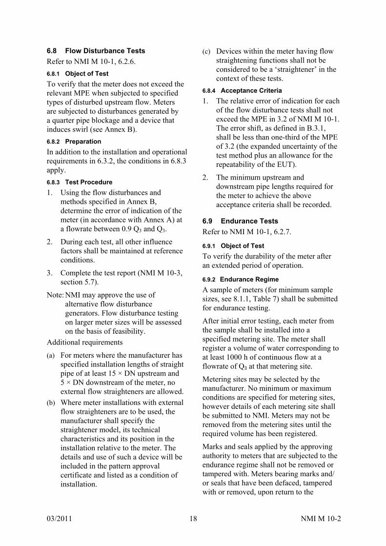
6.8 Flow Disturbance Tests
Refer to NMI M 10-1, 6.2.6.
6.8.1 Object of Test
To verify that the meter does not exceed the relevant MPE when subjected to specified types of disturbed upstream flow. Meters are subjected to disturbances generated by a quarter pipe blockage and a device that induces swirl (see Annex B).
6.8.2 Preparation
In addition to the installation and operational requirements in 6.3.2, the conditions in 6.8.3 apply.
6.8.3 Test Procedure
1. Using the flow disturbances and methods specified in Annex B, determine the error of indication of the meter (in accordance with Annex A) at a flowrate between 0.9 Q3 and Q3.
2. During each test, all other influence factors shall be maintained at reference conditions.
3. Complete the test report (NMI M 10-3, section 5.7).
Note: NMI may approve the use of alternative flow disturbance generators. Flow disturbance testing on larger meter sizes will be assessed on the basis of feasibility.
Additional requirements
(a) For meters where the manufacturer has specified installation lengths of straight pipe of at least 15 × DN upstream and 5 × DN downstream of the meter, no external flow straighteners are allowed.
(b) Where meter installations with external flow straighteners are to be used, the manufacturer shall specify the straightener model, its technical characteristics and its position in the installation relative to the meter. The details and use of such a device will be included in the pattern approval certificate and listed as a condition of installation.
(c) Devices within the meter having flow straightening functions shall not be considered to be a ‘straightener’ in the context of these tests.
6.8.4 Acceptance Criteria
1. The relative error of indication for each of the flow disturbance tests shall not exceed the MPE in 3.2 of NMI M 10-1. The error shift, as defined in B.3.1, shall be less than one-third of the MPE of 3.2 (the expanded uncertainty of the test method plus an allowance for the repeatability of the EUT).
2. The minimum upstream and downstream pipe lengths required for the meter to achieve the above acceptance criteria shall be recorded.
6.9 Endurance Tests
Refer to NMI M 10-1, 6.2.7.
6.9.1 Object of Test
To verify the durability of the meter after an extended period of operation.
6.9.2 Endurance Regime
A sample of meters (for minimum sample sizes, see 8.1.1, Table 7) shall be submitted for endurance testing.
After initial error testing, each meter from the sample shall be installed into a specified metering site. The meter shall register a volume of water corresponding to at least 1000 h of continuous flow at a flowrate of Q3 at that metering site.
Metering sites may be selected by the manufacturer. No minimum or maximum conditions are specified for metering sites, however details of each metering site shall be submitted to NMI. Meters may not be removed from the metering sites until the required volume has been registered.
Marks and seals applied by the approving authority to meters that are subjected to the endurance regime shall not be removed or tampered with. Meters bearing marks and/ or seals that have been defaced, tampered with or removed, upon return to the
03/2011 NMI M 10-2 19
approving authority, shall be excluded from further testing and evaluation in accordance with this section.
Water quality measurements may be taken at the specified metering sites during the endurance regime. If such measurements are performed in accordance with NMI requirements, the results can be referenced in the pattern approval certificate.
6.9.3 Preparation
The installation and operational requirements described in 6.3.2 shall apply.
6.9.4 Test Procedure
1. The approving authority shall mark and seal the meter(s) to be tested in accordance with this section.
2. Determine the initial errors of indication of the meter for at least the following flowrates, the error at each flowrate being measured twice: (a) between Q1 and 1.1 Q1; (b) between 0.33 (Q1 + Q3) and
0.37 (Q1 + Q3); (c) between 0.67 (Q1 + Q3) and
0.74 (Q1 + Q3); (d) between 0.9 Q3 and Q3; and (e) between 0.95 Q4 and Q4.
3. Subject the meter to the endurance regime described in 6.9.2.
4. Following the endurance regime, determine that the original mark(s) and seal(s) applied in step 1 have not been defaced, tampered with or removed.
5. Determine the final errors of indication of the meter in accordance with step 2.
6. During each test in steps 2 and 5, all other influence quantities shall be held at reference conditions.
7. Calculate the relative errors of indication for each flowrate in accordance with Annex B.
8. Complete test report NMI M 10-3, 5.8.
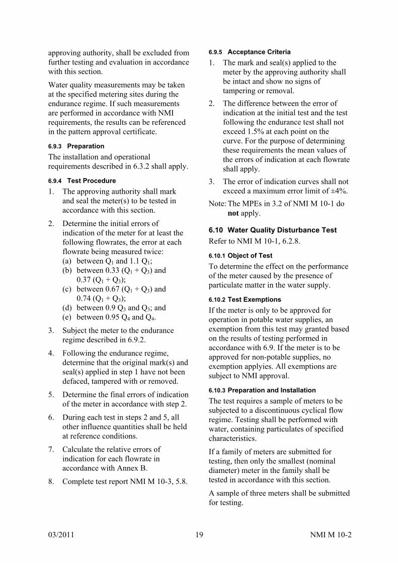
6.9.5 Acceptance Criteria
1. The mark and seal(s) applied to the meter by the approving authority shall be intact and show no signs of tampering or removal.
2. The difference between the error of indication at the initial test and the test following the endurance test shall not exceed 1.5% at each point on the curve. For the purpose of determining these requirements the mean values of the errors of indication at each flowrate shall apply.
3. The error of indication curves shall not exceed a maximum error limit of ±4%.
Note: The MPEs in 3.2 of NMI M 10-1 do not apply.
6.10 Water Quality Disturbance Test
Refer to NMI M 10-1, 6.2.8.
6.10.1 Object of Test
To determine the effect on the performance of the meter caused by the presence of particulate matter in the water supply.
6.10.2 Test Exemptions
If the meter is only to be approved for operation in potable water supplies, an exemption from this test may granted based on the results of testing performed in accordance with 6.9. If the meter is to be approved for non-potable supplies, no exemption applyies. All exemptions are subject to NMI approval.
6.10.3 Preparation and Installation
The test requires a sample of meters to be subjected to a discontinuous cyclical flow regime. Testing shall be performed with water, containing particulates of specified characteristics.
If a family of meters are submitted for testing, then only the smallest (nominal diameter) meter in the family shall be tested in accordance with this section.
A sample of three meters shall be submitted for testing.
03/2011 NMI M 10-2 20
Installation consists of a water supply (non-pressurised, pressurised tank, pump etc) and pipework.
6.10.3.1 Pipework
By way of example, the pipework may incorporate the following:
(a) one flow-regulating device (per line of meters in series, if necessary);
(b) one or more isolating valves;
(c) a device for measuring the temperature of the water upstream of the meters;
(d) devices for monitoring: the flowrate, the duration of cycles and the number of cycles;
(e) one flow-interrupting device for each line of meters in series;
(f) devices for measuring pressure at the inlet and outlet;
(g) a transparent viewing section of the pipework, allowing a visual check of the water supply and the suspended particulate matter.
The various devices shall not cause cavitation phenomena or other types of parasitic wear of the meters.
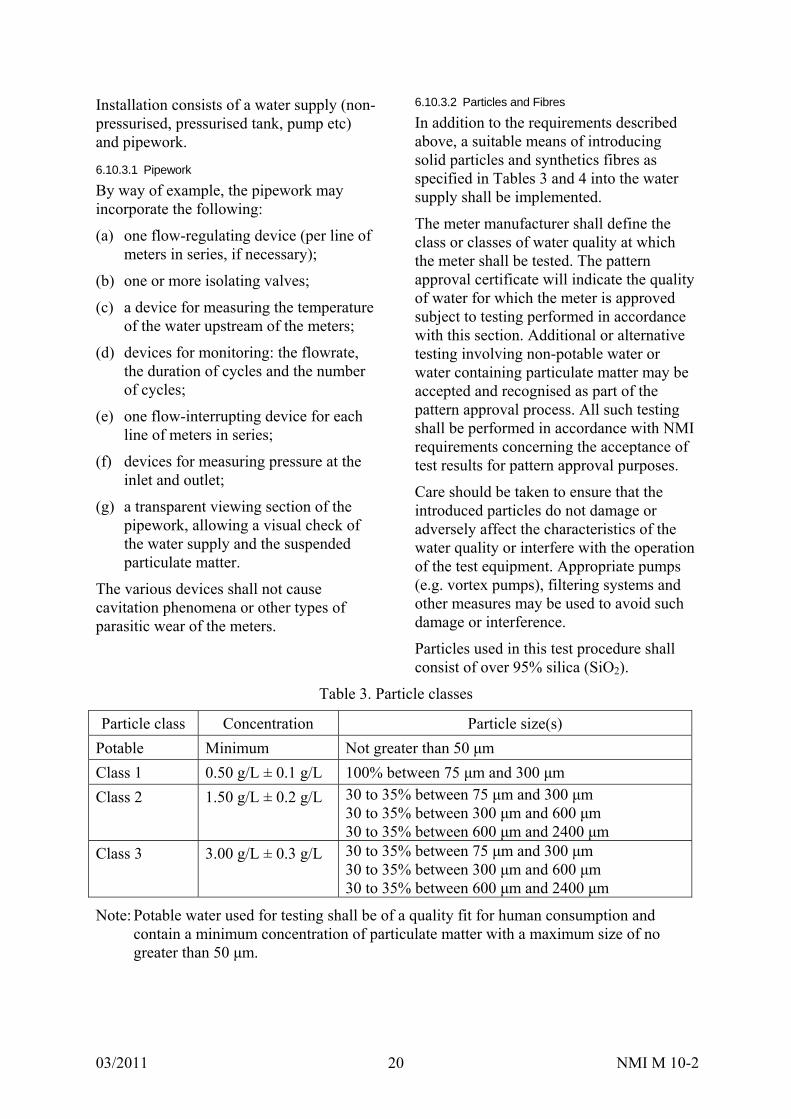
6.10.3.2 Particles and Fibres
In addition to the requirements described above, a suitable means of introducing solid particles and synthetics fibres as specified in Tables 3 and 4 into the water supply shall be implemented.
The meter manufacturer shall define the class or classes of water quality at which the meter shall be tested. The pattern approval certificate will indicate the quality of water for which the meter is approved subject to testing performed in accordance with this section. Additional or alternative testing involving non-potable water or water containing particulate matter may be accepted and recognised as part of the pattern approval process. All such testing shall be performed in accordance with NMI requirements concerning the acceptance of test results for pattern approval purposes.
Care should be taken to ensure that the introduced particles do not damage or adversely affect the characteristics of the water quality or interfere with the operation of the test equipment. Appropriate pumps (e.g. vortex pumps), filtering systems and other measures may be used to avoid such damage or interference.
Particles used in this test procedure shall consist of over 95% silica (SiO2).
Table 3. Particle classes
Particle class Concentration Particle size(s)
Potable Minimum Not greater than 50 μm
Class 1 0.50 g/L ± 0.1 g/L 100% between 75 μm and 300 μm
Class 2 1.50 g/L ± 0.2 g/L 30 to 35% between 75 μm and 300 μm 30 to 35% between 300 μm and 600 μm 30 to 35% between 600 μm and 2400 μm
Class 3 3.00 g/L ± 0.3 g/L 30 to 35% between 75 μm and 300 μm 30 to 35% between 300 μm and 600 μm 30 to 35% between 600 μm and 2400 μm
Note: Potable water used for testing shall be of a quality fit for human consumption and contain a minimum concentration of particulate matter with a maximum size of no greater than 50 μm.

03/2011 NMI M 10-2 21
Table 4. Water quality class 4
Class 4 Concentration Specifications
Particles 4.00 g/L ± 0.4 g/L Particle size between 1200 μm and 2400 μm
Synthetic fibres 0.10 g/L ± 0.01 g/L Approximate density: < 1000 kg/m3 Resistance to traction: > 400 MPa Module of elasticity: > 12 GPa Wetting (emersion time): < 90 s Thickness of fibre: 40 to 50 μm Width of fibre: 0.6 to 0.7 mm Length of fibre: 15 to 20 mm
Note: Test water of class 4 quality shall contain a combination of particles and synthetic fibres according to the specifications in Table 4.
6.10.3.3 Precautions to be Taken
The meters and connecting pipes shall be suitably bled of air.
The flow variation during the repeated opening and closing operations shall be progressive, so as to minimise water hammer.
The introduced particulate matter shall be kept suspended in the water supply throughout the duration of the discontinuous flow regime. The matter shall not be allowed to become trapped or sedimented within the pipework. If necessary the flowrate may need to be increased to ensure that the particulate matter remains suspended. A transparent viewing section of the pipework, allowing a visual check of the water supply is therefore recommended.
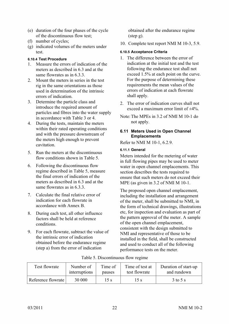
6.10.3.4 Flowrate Cycle
A complete cycle comprises the following four phases:
(a) a period from zero to the test flowrate;
(b) a period at constant test flowrate;
(c) a period from the test flowrate to zero;
(d) a period at zero flowrate.
6.10.3.5 Tolerance on Flowrate
The relative variation of the flow values shall not exceed ± 10% outside the opening, closing and stoppage periods. The meters on test may be used to check the flowrate.
6.10.3.6 Tolerance on Test Timing
The tolerance on the specified duration of each phase of the flow cycle shall not exceed ± 10%.
The tolerance on the total test duration shall not exceed ± 5%.
6.10.3.7 Tolerance on Number of Cycles
The number of cycles shall not be less than that stipulated, but shall not exceed this number by more than 1%.
6.10.3.8 Tolerance on Discharge Volume
The volume discharged throughout the test shall be equal to half the product of the specified test flowrate and the total theoretical duration of the test (operating periods plus transient and stoppage periods) with a tolerance of ± 5%.
This precision can be obtained by sufficiently frequent corrections of the instantaneous flows and operating periods.
6.10.3.9 Test Readings
During the test the following readings from the test rig shall be recorded at least once every 24 hour period, or once for every shorter period if the test is so divided: (a) water pressure upstream of the meters
under test; (b) water pressure downstream of the
meters under test; (c) water temperature upstream of the
meters under test; (d) flowrate through the meters under test;
03/2011 NMI M 10-2 22
(e) duration of the four phases of the cycle of the discontinuous flow test;
(f) number of cycles; (g) indicated volumes of the meters under
test.
6.10.4 Test Procedure 1. Measure the errors of indication of the
meters as described in 6.3 and at the same flowrates as in 6.3.3.
2. Mount the meters in series in the test rig in the same orientations as those used in determination of the intrinsic errors of indication.
3. Determine the particle class and introduce the required amount of particles and fibres into the water supply in accordance with Table 3 or 4.
4. During the tests, maintain the meters within their rated operating conditions and with the pressure downstream of the meters high enough to prevent cavitation.
5. Run the meters at the discontinuous flow conditions shown in Table 5.
6. Following the discontinuous flow regime described in Table 5, measure the final errors of indication of the meters as described in 6.3 and at the same flowrates as in 6.3.3.
7. Calculate the final relative error of indication for each flowrate in accordance with Annex B.
8. During each test, all other influence factors shall be held at reference conditions.
9. For each flowrate, subtract the value of the intrinsic error of indication obtained before the endurance regime (step a) from the error of indication
obtained after the endurance regime (step g).
10. Complete test report NMI M 10-3, 5.9.
6.10.5 Acceptance Criteria
1. The difference between the error of indication at the initial test and the test following the endurance test shall not exceed 1.5% at each point on the curve. For the purpose of determining these requirements the mean values of the errors of indication at each flowrate shall apply.
2. The error of indication curves shall not exceed a maximum error limit of ±4%.
Note: The MPEs in 3.2 of NMI M 10-1 do not apply.
6.11 Meters Used in Open Channel Emplacements
Refer to NMI M 10-1, 6.2.9.
6.11.1 General
Meters intended for the metering of water in full flowing pipes may be used to meter water in open channel emplacements. This section describes the tests required to ensure that such meters do not exceed their MPE (as given in 3.2 of NMI M 10-1.
The proposed open channel emplacement, including the installation and arrangement of the meter, shall be submitted to NMI, in the form of technical drawings, illustrations etc, for inspection and evaluation as part of the pattern approval of the meter. A sample of the open channel emplacement, consistent with the design submitted to NMI and representative of those to be installed in the field, shall be constructed and used to conduct all of the following performance tests on the meter.
Table 5. Discontinuous flow regime
Test flowrate Number of interruptions
Time of pauses
Time of test at test flowrate
Duration of start-up and rundown
Reference flowrate 30 000 15 s 15 s 3 to 5 s
03/2011 NMI M 10-2 23
6.11.2 Test Exemptions
If the meter is only to be used in the specified open channel emplacement then the tests outlined here may replace some of tests outlined in 6.2 to 6.9. However if the meter is also to be used in typical closed conduit situations then the tests in 6.2 to 6.10 shall be required for pattern approval. All exemptions are subject to NMI approval.
6.11.3 Installation Requirements
The design of the emplacement shall ensure that all the necessary operating conditions of the meter are not compromised and that the metrology of the meter is not adversely affected. The design of the installation shall ensure that under normal operating conditions:
a) the meter and any connecting pipework will be completely full of water and suitably bled of air at all times;
b) the meter is to be installed in the emplacement according to its specified orientation (vertical, horizontal etc);
c) a positive pressure will exist upstream of the meter at all times;
d) the emplacement will comply with the required environmental conditions of the meter;
e) the emplacement shall not cause the meter to exceed the MPE in the measurement of flowrate or volume.
6.11.4 Pattern Approval Certificate
A description of the open channel emplacement, in the form of technical drawings, as well as a statement allowing the meter to be used in the specified open channel emplacement shall be included in the pattern approval certificate. Specified conditions of the emplacement, such as minimum upstream and downstream pipe lengths shall also be stated on the pattern approval certificate. These conditions must be adhered to when installing the meter in-field for compliance with the pattern approval certificate.
6.11.5 Determination of Errors of Indication
6.11.5.1 Object of Test
To verify that the meter complies with the requirements of 3.2 in NMI M 10-1 when operating in a specified open channel emplacement.
6.11.5.2 Preparation
6.11.5.2.1 Description of the Test Rig
The methods described in 6.3.2.1 for determining the errors of indication of the meter shall be used. The requirements of 6.3.2.2.6.1 shall be met.
For the purpose of these tests, a meter should be tested without its temporary supplementary devices attached (if any).
The test rig consists, typically, of:
a) a water supply (non-pressurised tank, pump etc);
b) pipework;
c) a test section in which the meter and installation is placed;
d) means of establishing the desired flowrate and measuring that flowrate;
e) a calibrated reference device, e.g. a meter;
f) means for measuring the time of the test;
g) devices for automating the tests (if required);
h) means for measuring water temperature;
i) means for measuring the water pressure.
During the test, flow leakage, flow input and flow drainage shall not be permitted either between the meter/open channel emplacement and the reference device or from the reference device.
The design of the emplacement shall be such that in the upper, internal part of the meter, a positive pressure exists, even at zero flowrate.
03/2011 NMI M 10-2 24
6.11.5.2.2 Test Section
The test section shall include, in addition to the meter and the emplacement:
(a) one or more pressure tappings for the measurement of pressure, of which one pressure tapping is situated upstream of the meter within the pipework of the emplacement;
(b) means for measuring the temperature of the water close to the entry of the emplacement.
The presence of any pipe components or devices placed in or near the measuring section shall not cause cavitation or flow disturbances capable of altering the performance of the meter or causing errors of indication.
The design of the emplacement shall not cause cavitation or flow disturbances capable of altering the performance of the meter such that it exceeds the MPE requirements.
6.11.5.3 Precautions
6.11.5.3.1 Precautions during Tests
1. Check that the operation of the test rig is such that, during a test, the actual volume of water that flows through the meter(s) is equal to that measured by the reference device.
2. Bleed all air from the interconnecting pipework, the emplacement and the meter. The manufacturer may recommend a procedure that ensures that all air is bled from the meter.
3. Take all precautions necessary to avoid the effects of vibration and shock.
4. Ensure that the volume of water and time taken in each test is adequate to provide a representative result.
6.11.5.3.2 Errors of Test Commencement and Termination
Adequate precautions shall be taken to reduce the uncertainties resulting from operation of test rig components during the test.
The common test method would be to determine the error of indication by comparing the volume indications given by the meter operating under reference conditions in a specified open channel emplacement against a calibrated reference meter. If the tests are being conducted in this manner then the measurement of volume should only begin once the desired flow rate has been established and has stabilised.
If the tests are being conducted using the collection method, refer to the details of the precautions to be taken in 6.3.2.2.5.1 and 6.3.2.2.5.2 for two cases encountered using such a method.
6.11.5.3.3 Need for Straight Lengths of Pipe or a Flow Straightener
The accuracy of non-volumetric meters can be affected by upstream disturbance caused.
It is important to eliminate any such disturbances caused by the configuration of the test rig itself in order to ensure the repeatability and inter-laboratory comparison of test results. In order to counteract these disturbances: (a) the meter shall be installed in
accordance with the manufacturer’s instructions;
(b) the connecting pipework shall have an internal diameter matched to the relevant meter connection;
(c) if necessary, a flow straightener shall be installed upstream of the emplacement.
6.11.5.4 Calibrated Reference Device
6.11.5.4.1 Overall Uncertainty of the Value of Measured Actual Volume
When a test is conducted, the expanded uncertainty of the value of measured actual volume shall not exceed one-fifth of the MPE for pattern approval and one-third of the MPE for initial verification.
The estimated uncertainty shall be made according to the Guide to the Expression of Uncertainty in Measurement [4] with a coverage factor, k = 2.
03/2011 NMI M 10-2 25
6.11.5.4.2 Minimum Volume of the Calibrated Reference Device
The minimum volume permitted depends on requirements determined by the test start and end effects (timing error), and the design of the indicating device (value of the verification scale interval).
6.11.5.4.3 Cyclic Distortion of the Meter
The effects of a possible cyclic distortion on the reading of the meter (visual or automatic) shall be negligible.
6.11.5.5 Major Factors Affecting the Measurement of Errors of Indication
6.11.5.5.1 General
Variations in the pressure, flowrate and temperature in the test rig, and uncertainties in the precision of measurement of these physical quantities, are the principal factors affecting the measurement of the errors of indication of a meter.
6.11.5.5.2 Supply Pressure
The supply pressure shall be maintained at a constant value throughout the test at the chosen flowrate.
For all tests, the pressure upstream of the meter shall not vary by more than 10%.
The maximum uncertainty (k = 2) in the measurement of pressure shall be 5% of the measured value.
Pressure at the entrance to the meter shall not exceed the maximum admissible pressure for the meter.
6.11.5.5.3 Flowrate
A constant flowrate shall be maintained throughout the test.
The relative variation in the flowrate during each test (not including starting and stopping) shall not exceed ±5.0% from Q1 (inclusive) to Q4.
The flowrate value is the actual volume passed during the test divided by the time.
This flowrate variation condition is acceptable if the relative pressure variation does not exceed ±10% from Q1 (inclusive) to Q4.
6.11.5.5.4 Temperature
During a test, the temperature of the water shall not change by more than 5ºC.
The maximum uncertainty (k = 2) in the measurement of temperature shall not exceed 1ºC.
6.11.5.5.5 Orientation of Meter
The design of the open channel shall allow the meter to operate in accordance with the specified orientation requirements of the meter.
6.11.5.6 Test Procedure
1. Determine the errors of indication of the meter for at least the following flowrates, the error at each flowrate being measured twice:
(a) between Q1 and 1.1 Q1; (b) between 0.33 (Q1 + Q3) and
0.37 (Q1 + Q3); (c) between 0.67 (Q1 + Q3) and
0.74 (Q1 + Q3); (d) between 0.9 Q3 and Q3; and (e) between 0.95 Q4 and Q4.
2. Test the meter without its supplementary devices attached (if any).
3. During a test hold all other influence factors at reference conditions.
4. Measure the errors of indication at other flowrates if the shape of the error curve indicates that the MPEs may be exceeded.
5. Calculate the relative error of indication for each flowrate in accordance with Annex A.
6. Complete the test report (NMI M 10-3, section 5.10.1).
Note: Where the initial error curve is close to the MPE at a point other than at Q1 or Q3, if this error is shown to be typical of the meter type, the approving authority may choose to define an alternative flowrate for verification to be included in the pattern approval certificate.
03/2011 NMI M 10-2 26
6.11.5.7 Acceptance Criteria
1. The relative errors of indication for each of the flowrates shall not exceed the MPE in 3.2 of NMI M 10-1. If the error observed is greater than the MPE at one flowrate only, the test at that flowrate shall be repeated. The test shall be declared satisfactory if two out of the three results lie within the MPE and the arithmetic mean of the results for the three tests at that flowrate is less than or equal to the MPE.
2. If all the relative errors of indication of the meter have the same sign, at least one of the errors shall not exceed half the MPE. In all cases this requirement shall be applied equitably with respect to the water supplier and the consumer (NMI M 10-1, 3.4.3, paragraphs 3 and 7).
6.11.6 Flow Disturbance Tests
6.11.6.1 Object of Test
To verify that the meter operating in a specified open channel emplacement complies with the requirements of 3.2 in NMI M 10-1 while under the influence of disturbed flow, in the form of blockages, upstream of the emplacement. 6.11.6.2 Preparation
In addition to the emplacement and operational requirements described in 6.11.5, a quarter of the inlet of the emplacement shall be blocked off using a thin plate.
6.11.6.3 Test Procedure
1. Using the flow disturbances and methods specified in 6.11.6.2, determine the error of indication (in accordance with Annex A) of the meter at the flowrates: (a) between Q1 and 1.1 Q1; (b) between 0.9 Q3 and Q3.
2. The tests described in 1 above shall be repeated with the quarter plate being placed:
(a) at the top of the inlet; (b) at the bottom of the inlet; (c) to one side of the inlet.
3. During each test, all other influence factors shall be maintained at reference conditions.
4. If the error shift requirement specified in B.3.1 is not met, the tests have to be continued with the meter by incorporating a longer upstream and/or downstream straight pipe and/or flow conditioner into the emplacement.
5. Complete the test report (NMI M 10-3, section 5.10.2).
6.11.6.4 Acceptance Criteria
The relative error of indication for each of the flow disturbance tests shall not exceed the MPE in 3.2 of NMI M 10-1. The error shift as defined in B.3.1 shall be less than one-third of the MPE of 3.2 (the expanded uncertainty of the test method plus an allowance for the repeatability of the EUT). 6.11.7 Head Loss Test
6.11.7.1 Object of Test
To determine the maximum head loss through the meter and emplacement at any flowrate between Q1 and Q3. The head loss is defined as the level difference created by the flowing fluid passing through the EUT into a flooded discharge.
6.11.7.2 Preparation
The installation and operational requirements described in 6.11.5 shall apply.
6.11.7.3 Test Procedure
The test shall be performed as follows:
1. Flood the discharge to zero level difference and establish zero flow.
2. Decrease the outlet level until the desired flow is achieved.
3. Each flow shall then be maintained within tolerance specified below for a suitable period of time to minimise uncertainty in the head loss reading.
4. The head loss shall be determined at the following flows: (a) between Q1 and 1.1 Q1; (b) between 0.5 (Q1 + Q3) and 0.6
(Q1 + Q3); (c) between 0.9 Q3 and Q3; and
03/2011 NMI M 10-2 27
(d) between 0.95 Q4 and Q4 (or the highest flowrate recorded at the maximum head available).
5. Each test shall be carried out for a minimum of 30 min.
6. Complete the test report (NMI M 10-3, section 5.10.3).
6.11.7.4 Acceptance Criteria
The maximum head loss across the meter shall be determined and recorded. Accordingly, this value shall be marked on the meter casing, the indicating device dial, the identification plate or the meter cover if it is not detachable. Alternatively, the maximum head loss may be recorded in the memory of the meter provided it is made easily accessible (see 5.3.1).
6.12 Installation Tests
Refer to NMI M 10-1, 6.2.9.
6.12.1 General
A manufacturer may wish to test a meter in a specific installation design that the meter may commonly be subject to in the field, such as particular piping configurations. While this is not a requirement of pattern approval, provided that the testing is performed in accordance with the requirements below, recognition of such testing may form part of the pattern approval certificate.
The manufacturer shall submit detailed technical drawings and diagrams of the installation to NMI and the approving authority and these may form part of the pattern approval certificate.
6.12.2 Object of Test
To verify that a meter operating in a specified installation complies with the requirements of 3.2 in NMI M 10-1.
6.12.3 Preparation
The installation and operational requirements described in 6.3.2 shall apply. In addition, the test section shall include the specified installation/piping
configuration; with the meter installed as specified.
6.12.4 Test Procedure
1. Determine the errors of indication of the meter, for at least the following flowrates, the error at each flowrate being measured twice:
(a) between Q1 and 1.1 Q1; (b) between 0.33 (Q1 + Q3) and
0.37 (Q1 + Q3); (c) between 0.67 (Q1 + Q3) and
0.74 (Q1 + Q3); (d) between 0.9 Q3 and Q3; (e) between 0.95 Q4 and Q4.
2. Test the meter without its supplementary devices attached (if any).
3. During a test hold all other influence factors at reference conditions.
4. Measure the errors of indication at other flowrates if the shape of the error curve indicates that the MPEs may be exceeded.
5. Calculate the relative error of indication for each flowrate in accordance with Annex A.
6. Complete the test report (NMI M 10-3, section 5.11).
6.12.5 Acceptance Criteria
1. The relative errors of indication observed for each of the flowrates shall not exceed the MPE in 3.2 of NMI M 10-1. If the error observed on the meter is greater than the MPE at one flowrate only, the test at that flowrate shall be repeated. The test shall be declared satisfactory if two out of the three results lie within the MPE and the arithmetic mean of the results for the three tests at that flowrate is less than or equal to the MPE.
2. If all the relative errors of indication of the meter have the same sign, at least one of the errors shall not exceed half of the MPE. In all cases this requirement shall be applied equitably
03/2011 NMI M 10-2 28
with respect to the water supplier and the consumer (NMI M 10-1, 3.4.3, paragraphs 3 and 7).
6.13 Test for Cartridge Meters and Meters with Interchangeable Inserts
Refer to NMI M 10-1, 6.2.10.
6.13.1 Object of Test
To confirm that the cartridge meters or meters with interchangeable inserts are insensitive to the influence of connection interfaces produced in series production.
6.13.2 Preparation
Apply the installation and operational requirements described in 6.3.2.
Five connection interfaces and two measuring inserts or cartridges shall be selected from the meters presented for approval.
Correct matching of the insert with the connection interface (including necessary markings) shall be inspected prior to testing.
6.13.3 Test Procedure
1. Five connection interfaces of identical type shall be tested with two measuring inserts each, resulting in ten accuracy curves.
2. The connection interfaces and inserts shall be tested and the errors of indication shall be determined for at least the following flowrates, the error at each flowrate being measured twice: (a) between Q1 and 1.1 Q1; (b) between 0.33 (Q1 + Q3) and
0.37 (Q1 + Q3); (c) between 0.67 (Q1 + Q3) and
0.74 (Q1 + Q3); (d) between 0.9 Q3 and Q3; (e) between 0.95 Q4 and Q4.
3. During each test, all other influence factors shall be maintained at reference conditions.
4. Complete the test report (NMI M 10-3, section 5.12).
6.13.4 Acceptance Criteria
The relative errors of indication for all of the tests shall not exceed the MPE in 3.2 of NMI M 10-1.
Error variation within the five tests corresponding to each measuring insert shall not exceed 1/5 of the MPE in 3.2 of NMI M 10-1 (i.e. ±0.5%).
6.14 Maintenance Tests
Refer to NMI M 10-1, 6.2.11.
6.14.1 General
The policy paper National Framework for Non-urban Water Metering [6] allows a pattern approval certificate to provide guidance on common types of maintenance activities which:
(a) do not and cannot affect the metrological performance (and therefore can be undertaken by an uncertified person operating under established work practices and/or maintenance plan);
(b) do not affect the metrological performance when undertaken by a suitably trained and certified maintainer (and therefore trigger the need for subsequent verification when undertaken by an uncertified maintainer);
(c) may affect the metrological performance even when undertaken by a trained and certified maintainer (and therefore trigger the need for subsequent verification).
Any maintenance activity which does not require the verification seal(s) to be broken will not typically affect the metrological performance of the meter. There are exceptions that exist in some meter types and these will be noted in the individual pattern approval certificates.
Any maintenance activity which does require the verification seal(s) to be broken will typically be deemed to have affected the metrological performance of a meter and therefore that meter will require subsequent verification.

03/2011 NMI M 10-2 29
However, if it can be proven that a specified maintenance activity, when performed by a suitably trained and certified maintainer, does not affect the metrological performance of a meter, an exception may be made. 6.14.2 Documentation
A manufacturer may test a specified maintenance activity as part of the pattern approval process. While this is not a requirement of pattern approval, provided that the testing is performed in accordance with NMI requirements, recognition of successful test results may form part of the pattern approval certificate.
For any maintenance activity that is tested, the applicant shall provide:
(a) reference to appropriate maintenance instructions that form part of a publication related directly to the meter; such as an instruction booklet or product manual; and/or
(b) detailed instructions and procedures outlining how the maintenance is to be performed.
This information will be included as part of the pattern approval certificate.
6.14.3 Certification
The pattern approval certificate will list the specified maintenance procedures that have been tested and are deemed to have no adverse affect on the metrological performance of a meter when undertaken by a suitably trained and certified maintainer. Any and all other maintenance procedures that are performed on a meter, that are not listed on the pattern approval certificate (which require the verification seal(s) to be broken), are deemed to affect the metrological performance of the meter and therefore subsequent verification is required.
All information included on a pattern approval certificate relating to the maintenance of a meter is intended as guidance only.
Note: Maintenance procedures that are listed on the pattern approval certificate are specific to that meter only. Maintenance procedures listed on one pattern approval certificate cannot be used as guidance to perform maintenance on a meter with a different certificate; any such maintenance will be deemed to have affected the metrology of the meter and therefore subsequent verification is required.
6.14.4 Object of Test
To verify that a specified maintenance procedure does not affect the metrological performance of the meter.
6.14.5 Preparation
The installation and operational requirements described in 6.3.2 shall apply. The meter shall have subsequently been tested in accordance with 6.3.2.
6.14.6 Test Procedure
1. Perform the specified maintenance procedure.
2. If the meter has been removed (as a result of maintenance), re-install the meter into the test rig as per 6.3.2.
3. Determine the errors of indication of the meter, for at least the following flowrates, the error at each flowrate being measured twice:
(a) between Q1 and 1.1 Q1; (b) between 0.33 (Q1 + Q3)
and 0.37 (Q1 + Q3); (c) between 0.67 (Q1 + Q3)
and 0.74 (Q1 + Q3); (d) between 0.9 Q3 and Q3; (e) between 0.95 Q4 and Q4.
4. During a test hold all other influence factors at reference conditions.
5. Calculate the relative error of indication for each flowrate in accordance with Annex A.
6. Complete test report (NMI M 10-3, section 5.13).
03/2011 NMI M 10-2 30
6.14.7 Acceptance criteria
The relative errors of indication observed for each of the flowrates shall not deviate from the corresponding relative errors of indication observed in 6.3.3 by more than the uncertainty associated with the test method itself (see NMI M 10-1, 7.1).
7. PERFORMANCE TESTS FOR ELECTRONIC METERS AND MECHANICAL METERS FITTED WITH ELECTRONIC DEVICES
7.1 General Requirements
Refer to NMI M 10-1, A.1.
This section defines the performance tests which are intended to verify that meters with electronic devices perform and function as intended in a specified environment and under specified conditions. Each test indicates, where appropriate, the reference conditions for determining the intrinsic error.
These performance tests are additional to the tests described in 6 and apply to complete meters, to separable parts of a meter, and, if required, to ancillary devices.
When the effect of one influence quantity is being evaluated, all other influence quantities are to be held at the reference conditions (see 7.1.2).
Note: The reference conditions in this section differ from those in 3 which apply to the testing in 6 (see 3).
The pattern approval tests specified in this section may be carried out in parallel with the tests specified in 6, using examples of the same model of the meter, or its separable parts.
7.1.1 Environmental Classification
Refer to NMI M 10-1, A.2.
For each performance test, typical test conditions are indicated; they correspond to the mechanical, electrical and climatic environmental conditions to which meters are exposed.
Meters with electronic devices are divided into three classes according to these environmental conditions: class B for fixed meters installed in a
building; class O for fixed meters installed
outdoors; and class M for mobile meters.
They are also divided into two electromagnetic environment classes: class E1 residential, commercial and
light industrial; and class E2 industrial.
Following consultation and agreement with NMI, the pattern approval applicant may also indicate specific environmental conditions in the documentation supplied to the approving authority, based on the intended use of the meter. In this case, approving authority will carry out performance tests at severity levels corresponding to these environmental conditions. These severity levels must not be less than class B. See NMI 10-1, Table A.1 for more details of severity levels.
In all cases the approving authority shall verify that the conditions of use are met.
Note: Meters which are approved at a given severity level are also suitable for lower severity levels.
7.1.2 Reference Conditions
Refer to NMI M 10-1, 6.1 and A.3.
Ambient air temperature: 20 ± 5°C Ambient relative humidity: 60 ± 15% Ambient atmospheric pressure: 86 to 106 kPa Power voltage: nominal voltage (Unom) Power frequency: nominal frequency (fnom)
During each test, the temperature and relative humidity shall not vary by more than 5°C or 10% respectively within the reference range.

03/2011 NMI M 10-2 31
7.1.3 Test Volumes for Measuring the Error of Indication
Refer to NMI M 10-1, A.5(1).
Some influence quantities should have a constant effect on the error of indication of a meter and not a proportional effect related to the measured volume.
In other tests the effect of the influence quantity applied to a meter is related to the measured volume. In these cases, in order to be able to compare results obtained in different laboratories, the minimum test volume for measuring the error of indication of the meter shall correspond to that delivered in 1 min at the over-load flowrate, Q4.
However, some tests may require more than 1 min, in which case they shall be carried out in the shortest possible time, taking into consideration the measurement uncertainty.
7.1.4 Influence of the Water Temperature
Refer to NMI M 10-1, A.5(2).
Dry heat, cold and damp heat tests are concerned with measuring the effects of ambient air temperature on the performance of the meter. However, the presence of the measurement transducer, filled with water, may also influence heat dissipation in electronic components.
A simulation of the measurement transducer may be used for testing all electronic components. Where simulated tests are used, they shall replicate the effects caused by the presence of water for those electronic devices which are normally attached to the flow sensor, and the reference conditions shall be applied during the tests.
7.1.5 Requirements for Environmental Tests
The following requirements are associated with the environmental tests and the relevant standards to be applied are listed in the appropriate sections:
(a) pre-conditioning of the EUT;
(b) any deviations in the procedure from the relevant standard;
(c) initial measurements;
(d) state of the EUT during conditioning;
(e) severity levels, values of the influence factor and duration of exposure;
(f) measurements required and/or the loading during conditioning;
(g) recovery of the EUT;
(h) final measurements;
(i) the acceptance criteria for the EUT passing a test.
Where no standard exists for a specific test, the essential requirements for the test are given in this document.
7.1.6 Meter Scanning Rates
Many tests specified in this section require a periodic or intermittent influence factor to be applied to the meter while a determination of the error of indication is made. For the purposes of the following tests, the meter shall be set to its highest (most frequent) scanning rate to ensure the adequate application of the influence factor in question: power voltage variation (7.5); short time power reductions (7.8); bursts (7.9); electrostatic discharge (7.10); and electromagnetic susceptibility (7.11).
7.1.7 Categorisation of the EUT
Refer to NMI M 10-1, 6.2.12.3.
7.1.7.1 General
For the purpose of testing, the EUT shall be categorised as one of the cases, A to E, as described below.
Case A No performance test (as mentioned in this section) is required.
Case B The EUT is the complete meter: the test shall be carried out with water flowing in the volume or flow sensor and the meter operating as designed.

03/2011 NMI M 10-2 32
Case C The EUT is the measurement transducer (including flow or volume sensor): the test shall be carried out with water flowing in the volume or flow sensor and the meter operating as designed.
Case D The EUT is the electronic calculator (including the indicating device) or the ancillary device: the test shall be carried out with water flowing in the volume or flow sensor and the meter operating as designed.
Case E The EUT is the electronic calculator (including the indicating device) or the ancillary device: the test may be carried out with simulated measurement signals without water in the volume or flow sensor.
Note: The approving authority may apply an appropriate category, A to E, for approval testing of meters having technology which is not included in 7.1.7.2 to 7.1.7.5.
7.1.7.2 Turbine Meters
(a) The meter is not fitted with electronic devices: Case A.
(b) The measurement transducer and the electronic calculator including the indicating device are in the same housing: Case B.
(c) The measurement transducer is separate from the electronic calculator, but not fitted with electronic devices: Case A.
(d) The measurement transducer is separate from the electronic calculator, and fitted with electronic devices: Case C.
(e) The electronic calculator including the indicating device is separate from the measurement transducer and simulation of the measurement signals is not possible: Case D.
(f) The electronic calculator including the indicating device is separate from the measurement transducer and
simulation of the measurement signals is possible: Case E.
7.1.7.3 Electromagnetic Meters
(a) The measurement transducer and the electronic calculator including the indicating device are in the same housing: Case B.
(b) The flow sensor, consisting only of the pipe, the coil and the two meter electrodes, is without any additional electronic devices: Case A.
(c) The measurement transducer including the flow sensor is separate from the electronic calculator, and in one housing: Case C.
(d) The electronic calculator including the indicating device is separate from the measurement transducer and simulation of the measurement signals is not possible: Case D.
(e) The electronic calculator including the indicating device is separate from the measurement transducer and simulation of the measurement signals is possible: Case E.
7.1.7.4 Ultrasonic Meters, Coriolis Meters, Fluidic Meters
(a) The measurement transducer and the electronic calculator including the indicating device are in the same housing: Case B.
(b) The measurement transducer is separate from the electronic calculator and fitted with electronic devices: Case C.
(c) The electronic calculator including the indicating device is separate from the measurement transducer and simulation of the measurement signals is not possible: Case D.
(d) The electronic calculator including the indicating device is separate from the measurement transducer and simulation of the measurement signals is possible: Case E.
7.1.7.5 Ancillary devices
(a) The ancillary device is part of the meter, a part of the measurement
03/2011 NMI M 10-2 33
transducer or part of the electronic calculator: Cases A to E.
(b) The ancillary device is separate from the meter, but not fitted with electronic devices: Case A.
(c) The ancillary device is separate from the meter, and simulation of the input signals is not possible: Case D.
(d) The ancillary device is separate from the meter, and simulation of the input signals is possible: Case E.
7.2 Dry Heat (Non-condensing)
Refer to NMI M 10-1, A.5.1.
7.2.1 Object of Test
To verify that the EUT complies with the provisions of 3.2 in NMI M 10-1 during the application of high ambient temperatures.
7.2.2 Preparation
Test arrangements: IEC 60068-2-2 [7].
Guidance on test arrangements: IEC 60068-3-1 [8] and IEC 60068-1 [3].
7.2.3 Test Procedure
1. Do not pre-condition the EUT.
2. Measure the error of indication of the EUT at the reference flowrate and at the following test conditions: (a) at the reference air temperature of
20 5°C, before conditioning the EUT;
(b) at an air temperature of 55 2°C, after the EUT has been stabilised at this temperature for a period of 2 h;
(c) at the reference air temperature of 20 5°C, after recovery of the EUT.
3. Calculate the relative error of indication for each test condition.
4. During the application of the test conditions, check that the EUT is functioning correctly.
5. Complete the test report (NMI M 10-3, section 6.1).
Additional requirement:
When measuring the errors of indication, the installation and operational conditions described in 6.3.2 shall be followed and the reference conditions shall be applied unless otherwise specified.
7.2.4 Acceptance Criteria
During the application of the test conditions on the EUT:
1. All functions shall operate as designed.
2. The relative error of indication shall not exceed the MPE (NMI M 10-1, 3.2).
7.3 Cold
Refer to NMI M 10-1, A.5.2.
7.3.1 Object of Test
To verify that the EUT complies with the provisions of 3.2 in NMI M 10-1 during the application of low ambient temperatures.
7.3.2 Preparation
Test arrangements: IEC 60068-2-1 [9].
Guidance on test arrangements: IEC 60068-3-1 [8] and IEC 60068-1 [3].
7.3.3 Test Procedure
1. Do not pre-condition the EUT.
2. Measure the error of indication of the EUT at the reference flowrate and at the reference air temperature.
3. Stabilise the air temperature at either -10°C (classes O and M) or +5°C (class B) for a period of 2 h.
4. Measure the error of indication of the EUT at the reference flowrate at an air temperature of either –10°C (classes O and M) or +5°C (class B).
5. After recovery of the EUT, measure the error of indication of the EUT at the reference flowrate and at the reference air temperature.
6. Calculate the relative error of indication for each test.
03/2011 NMI M 10-2 34
7. During the application of the test conditions, check that the EUT is functioning correctly.
8. Complete the test report (NMI M 10-3, section 6.2).
Additional requirements:
(a) If it is necessary to have water in the flow sensor, the water temperature shall be held at the reference temperature.
(b) When measuring the errors of indication, the installation and operational conditions described in 6.3.2 shall be followed and the reference conditions shall be applied unless otherwise specified.
7.3.4 Acceptance Criteria
During the application of the stabilised test conditions on the EUT:
1. All functions shall operate as designed.
2. The relative error of indication shall not exceed the MPE (NMI M 10-1, 3.2).
7.4 Damp Heat, Cyclic (Condensing)
Refer to NMI M 10-1, A.5.3.
7.4.1 Object of Test
To verify that the EUT complies with the provisions of 3.2 in NMI M 10-1 after applying conditions of high humidity combined with cyclic temperature changes.
7.4.2 Preparation
Test arrangements: IEC 60068-2-30 [10].
Guidance on test arrangements: IEC 60068-3-4 [11].
7.4.3 Test Procedure
1. Pre-condition the EUT.
2. Expose the EUT to cyclic temperature variations between the lower temperature of 25°C and the upper temperature of either 55°C (classes O and M) or 40°C (class B). Maintain the relative humidity above 95% during the temperature changes and during the phases at low temperature, and at 93% at the upper temperature phases.
Condensation should occur during the temperature rise.
3. Allow the EUT to recover.
4. After recovery, check that the EUT is functioning correctly.
5. Measure the error of indication of the EUT at the reference flowrate.
6. Calculate the relative error of indication.
7. Complete the test report (NMI M 10-3, section 6.3).
Additional requirements:
(a) The power supply to the EUT is switched off during steps 1 to 3.
(b) When measuring the error of indication, the installation and operational conditions described in 6.3.2 shall be followed and the reference conditions shall be applied unless otherwise specified.
7.4.4 Acceptance Criteria
After the application of the influence factor and recovery on the EUT:
1. All functions shall operate as designed.
2. The relative error of indication at the reference conditions shall not exceed the MPE (NMI M 10-1, 3.2).
7.5 Power Voltage Variation
Refer to NMI M 10-1, A.5.4.
7.5.1 Meters Powered by Direct AC and AC/DC Converters (NMI M 10-1, A.5.4.1)
7.5.1.1 Object of Test
7.5.1.1.1 Single Voltage
To verify that electronic devices which operate at a single nominal value of mains voltage (Unom) at a nominal frequency (fnom) comply with the provisions of 3.2 in NMI M 10-1 during static deviations of the AC (single-phase) mains power supply, applied in accordance with the requirements of NMI M 10-1 (A.5.4.1).
7.5.1.1.2 Voltage Range
To verify that electronic devices which operate within a nominal range of mains

03/2011 NMI M 10-2 35
voltage, having an upper limit Uu and a lower limit Ul, at a nominal frequency (fnom) comply with the provisions of 3.2 in NMI M 10-1 during static deviations of the AC (single-phase) mains power supply, applied in accordance with the requirements of NMI M 10-1 (A.5.4.1).
7.5.1.2 Preparation
Test arrangements: IEC 61000-4-11 [12] IEC 61000-2-1 [13] IEC 61000-2-2 [14] IEC 61000-4-1 [15] IEC 60654-2 [16] IEC 61000-2-12 [17] IEC 61000-4-5 [18]
7.5.1.3 Test Procedure
1. Expose the EUT to power voltage variations, while the EUT is operating under reference conditions.
2. Measure the error of indication of the EUT during the application of the upper mains voltage limit Unom + 10% (single voltage) or Uu +10% (voltage range).
3. Measure the error of indication of the EUT during the application of the lower mains voltage limit Unom – 15% (single voltage) or Ul – 15% (voltage range).
4. Calculate the relative error of indication for each test condition.
5. Check that the EUT is functioning correctly during the application of each power supply variation.
6. Complete the test report (NMI M 10-3, section 6.4.1).
Additional requirements:
(a) During the measurement of the error of indication the EUT shall be subjected to the reference flowrate (NMI M 10-1, 6.1).
(b) When measuring the errors of indication, the installation and operational conditions described in 6.3.2 shall be followed and the reference conditions shall be applied unless otherwise specified.
7.5.1.4 Acceptance Criteria
During the application of the influence factor on the EUT:
1. All functions shall operate as designed.
2. The relative error of indication shall not exceed the MPE (NMI M 10-1, 3.2).
7.5.2 Meters Powered by Primary DC Batteries (NMI M 10-1, A.5.4.2)
7.5.2.1 Object of Test
To verify that battery powered electronic devices comply with the provisions of 3.2 in NMI M 10-1 during static deviations of the DC, primary battery, power supply voltage.
7.5.2.2 Preparation
No references to standards for test methods can be given.
7.5.2.3 Test Procedure
1. Expose the EUT to power voltage variations, while the EUT is operating under reference conditions.
2. Measure the error of indication of the EUT during the application of the upper battery voltage limit Umax.
3. Measure the error of indication of the EUT during the application of the lower battery voltage limit Umin.
4. Calculate the relative error of indication for each test condition in accordance with Annex B.
5. Check that EUT is functioning correctly during the application of each power supply variation.
6. Complete the test report (NMI M 10-3, section 6.4.2).
Additional requirement:
(a) During the measurement of the error of indication the EUT shall be subjected to the reference flowrate.
When measuring the errors of indication, the installation and operational conditions described in 6.3.2 shall be followed and the reference conditions shall be applied unless otherwise specified.
03/2011 NMI M 10-2 36
7.5.2.4 Acceptance Criteria
During the application of the voltage variations on the EUT:
1. All functions shall operate as designed.
2. The relative error of indication shall not exceed the MPE (NMI M 10-1, 3.2).
7.6 Vibration (Random)
Refer to NMI M 10-1, A.5.5.
7.6.1 Object of Test
To verify that the EUT complies with the provisions of 3.2 in NMI M 10-1 after the application of random vibrations.
Note: While this test is only mandatory for meters mounted in mobile installations (class M), it is recommended that all meters be subjected to the testing described in this section.
7.6.2 Preparation
Test arrangements: IEC 60068-2-64 [19] and IEC 60068-2-47 [20].
7.6.3 Test Procedure
1. Mount the EUT on a rigid fixture by its normal mounting means, such that the gravitational force acts in the same direction as it would in normal use. However, if the gravitational effect is insignificant, and the meter is not marked H or V, the EUT may be mounted in any position.
2. Apply random vibrations over the frequency range of 10 to 150 Hz in three, mutually perpendicular axes in turn, for a period of at least 2 min per axis.
3. Allow the EUT a period for recovery.
4. Examine the EUT for correct functioning.
5. Measure the error of indication of the EUT at the reference flowrate.
6. Calculate the relative error of indication.
7. Complete the test report (NMI M 10-3, section 6.5).
Additional requirements:
(a) Where the flow sensor is included in the EUT, it shall not be filled with water during the application of the disturbance.
(b) The power supply to the EUT is switched off during steps 1, 2 and 3.
(c) During the application of the vibrations the following conditions shall be met: total RMS level: 7 m.s–2 ASD level 10–20 Hz: 1 m2.s–3 ASD level 20–150 Hz: –3 dB/octave
When measuring the errors of indication of the EUT, the installation and operational conditions described in 6.3.2 shall be followed and the reference conditions shall be applied unless otherwise specified.
7.6.4 Acceptance Criteria
After the application of the vibrations and recovery on the EUT:
1. All functions shall operate as designed.
2. The relative error of indication shall not exceed the MPE (NMI M 10-1, 3.2).
7.7 Mechanical Shock
Refer to NMI M 10-1, A.5.6.
7.7.1 Object of Test
To verify that the EUT complies with the provisions of 3.2 in NMI M 10-1 after the application of the mechanical shock test (dropping onto face).
Note: While this test is only mandatory for meters mounted in mobile installations (class M), it is recommended that all meters be subjected to the testing described in this section.
7.7.2 Preparation
Test arrangements: IEC 60068-2-31 [21] and IEC 60068-2-47 [20].
7.7.3 Test Procedure
1. The EUT shall be placed on a rigid, level surface in its normal position of use and tilted towards one bottom edge until the opposite edge of the EUT is
03/2011 NMI M 10-2 37
50 mm above the rigid surface. However, the angle made by the bottom of the EUT and the test surface shall not exceed 30o.
2. Allow the EUT to fall freely onto the test surface.
3. Repeat steps 1 and 2 for each bottom edge.
4. Allow the EUT a period for recovery.
5. Examine the EUT for correct functioning.
6. Measure the error of indication of the EUT at the reference flowrate.
7. Calculate the relative error of indication.
8. Complete the test report (NMI M 10-3, section 6.6).
Additional requirements:
(a) Where the flow sensor is part of the EUT, it shall not be filled with water during the application of the disturbance.
(b) The power supply to the EUT shall be switched off during steps 1, 2 and 3.
7.7.4 Acceptance Criteria
After the application of the disturbance and recovery on the EUT:
1. All functions shall operate as designed.
2. The relative error of indication shall not exceed the MPE (NMI M 10-1, 3.2).
7.8 Short-time Power Reductions
Refer to NMI M 10-1, A.5.7.
7.8.1 Object of Test
To verify that EUT which is mains powered, complies with the provisions of 3.2 in NMI M 10-1 during the application of short time, mains voltage interruptions and reductions.
7.8.2 Preparation
Test arrangements: IEC 61000-4-11 [12] IEC 61000-2-1 [13] IEC 61000-2-2 [14] IEC 61000-4-1 [15]
7.8.3 Test Procedure
1. Measure the error of indication of the EUT before applying power reduction test.
2. Measure the error of indication of the EUT during the application of at least ten voltage interruptions and ten voltage reductions.
3. Calculate the relative error of indication for each test condition.
4. Subtract the error of indication of the meter measured before applying the power reductions from that measured during the application of the power reductions.
5. Examine the EUT for correct functioning.
6. Complete the test report (NMI M 10-3, section 6.7).
Additional requirements:
(a) Voltage interruptions and voltage reductions are applied throughout the period required to measure the error of indication of the EUT.
(b) Voltage interruptions: the supply voltage is reduced from its nominal value (Unom) to zero voltage, for a duration equal to half a cycle of line frequency.
(c) Voltage interruptions are applied in groups of ten.
(d) Voltage reductions: the supply voltage is reduced from nominal voltage to 50% of nominal voltage for a duration equal to one cycle of the power supply frequency.
(e) Voltage reductions are applied in groups of ten.
(f) Each individual voltage interruption or reduction is initiated, terminated and repeated at zero crossings of the supply voltage.
(g) The mains voltage interruptions and reductions are repeated at least ten times
03/2011 NMI M 10-2 38
with a time interval of at least 10 s between each group of interruptions and reductions. This sequence is repeated throughout the duration of the measurement of the error of indication of the EUT.
(h) During the measurement of the error of indication the EUT shall be subjected to the reference flowrate.
(i) When measuring the errors of indication, the installation and operational conditions described in 6.3.2 shall be followed and the reference conditions shall be applied unless otherwise specified.
(j) When the EUT is designed to operate over a range of supply voltage, voltage reductions and interruptions shall be initiated from the mean voltage of the range.
7.8.4 Acceptance Criteria
After the application of the short time power reductions on the EUT:
1. All functions shall operate as designed.
2. The difference between the relative error of indication obtained during the test and that obtained at the same flowrate before the test under reference conditions, shall not exceed half of the MPE (NMI M 10-1, 3.2).
7.9 Bursts
Refer to NMI M 10-1, A.5.8.
7.9.1 Object of Test
To verify that the EUT (including its external cables) complies with the provisions of 3.2 in NMI M 10-1 during the application of voltage spikes, superimposed on the mains voltage.
7.9.2 Preparation
Test arrangements: IEC 61000-2-1 [13] IEC 61000-2-2 [14] IEC 61000-4-1 [15] IEC 61000-4-4 [22]
7.9.3 Test Procedure
1. Measure the error of indication of the EUT before applying the electrical bursts.
2. Measure the error of indication of the EUT during the application of bursts of transient voltage spikes, of double exponential waveform.
3. Calculate the relative error of indication for each test condition.
4. Subtract the error of indication of the meter measured before applying the bursts from that measured during the application of the bursts.
5. Examine the EUT for correct functioning.
6. Complete the test report (NMI M 10-3, section 6.8).
Additional requirements:
(a) Each spike shall have an amplitude (positive or negative) of 1000 V for class E1 instruments, or 2000 V for class E2 instruments (see 7.1.1), phased randomly, with a rise time of 5 ns and a half amplitude duration of 50 ns.
(b) If data or communications ports (or cabling) are part of the meter design then voltage spikes shall also be applied to these ports in addition to mains voltage ports. In this case, each spike shall have an amplitude (positive or negative) of 500 V for class E1 instruments, or 1000 V for class E2 instruments, phased randomly, with a rise time of 5 ns and a half amplitude duration of 50 ns.
(c) The burst length shall be 15 ms, the burst period (repetition time interval) shall be 300 ms.
(d) All bursts shall not be applied asynchronously in common mode (asymmetrical voltage) during the measurement of the error of indication of the EUT.

03/2011 NMI M 10-2 39
(e) During the measurement of the error of indication the EUT shall be operated at the reference flowrate.
(f) When measuring the error of indication, the installation and operational conditions of the EUT, described in 6.3.2, shall be followed and the reference conditions shall be applied unless otherwise specified.
7.9.4 Acceptance Criteria
After the application of the disturbance on the EUT:
1. All functions shall operate as designed.
2. The difference between the relative error of indication obtained during the test and that obtained at the same flowrate before the test under reference conditions, shall not exceed half of the MPE (NMI M 10-1, 3.2).
7.10 Electrostatic Discharge
Refer to NMI M 10-1, A.5.9.
7.10.1 Object of Test
To verify that the EUT complies with the provisions of 3.2 in NMI M 10-1 during the application of direct and indirect electrostatic discharges.
7.10.2 Preparation
Test arrangements: IEC 61000-2-1 [13] IEC 61000-2-2 [14] IEC 61000-4-1 [15] IEC 61000-4-2 [23]
7.10.3 Test Procedure
1. Measure the error of indication of the EUT before applying the electrostatic discharges.
2. Charge a capacitor of 150 pF capacitance by means of a suitable DC voltage source. Then discharge the capacitor through the EUT by connecting one terminal of the supporting chassis to ground and the other via a 330 resistor, to surfaces of the EUT which are normally
accessible to the operator. The following conditions shall be applied: (a) include the paint penetration
method, if appropriate; (b) for each contact discharge, a
voltage of 6 kV shall be applied; (c) for each air discharge, a voltage of
8 kV shall be applied; (d) for direct discharges, the air
discharge method shall be used where the manufacturer has declared a coating to be insulating;
(e) at each test location, at least ten direct discharges shall be applied at intervals of at least 10 s between discharges, during the same measurement or simulated measurement;
(f) for indirect discharges, a total of ten discharges shall be applied on the horizontal coupling plane and a total of ten discharges for each of the various positions of the vertical coupling plane.
3. Measure the error of indication of the EUT during the application of electrostatic discharges.
4. Calculate the relative error of indication for each test condition in accordance with Annex B.
5. Determine if the significant fault has been exceeded by subtracting the error of indication of the meter measured before applying the electrostatic discharges from that measured after applying the electrostatic discharges.
6. Examine the EUT for correct functioning.
7. Complete the test report (NMI M 10-3, section 6.9).
Additional requirements:
(a) When measuring the error of indication the EUT shall be subjected to the reference flowrate.
(b) When measuring the error of indication, the installation and operational conditions described in
03/2011 NMI M 10-2 40
6.3.2 shall be followed and the reference conditions shall be applied unless otherwise specified.
7.10.4 Acceptance Criteria
After the application of the disturbance on the EUT:
1. All functions shall operate as designed.
2. The difference between the relative error of indication obtained during the test and that obtained before the test at the same flowrate under reference conditions, shall not exceed half of the MPE (NMI M 10-1, 3.2).
3. For tests at zero flowrate the meter totalisation shall not change by more than the value of the verification interval.
7.11 Electromagnetic Susceptibility
Refer to NMI M 10-1, A.5.10.
7.11.1 Object of Test
To verify that the EUT complies with the provisions of 3.2 in NMI M 10-1 during the application of radiated electromagnetic fields.
7.11.2 Preparation
Test arrangements: IEC 61000-2-1 [13] IEC 61000-2-2 [14] IEC 61000-4-1 [15] IEC 61000-4-3 [24] IEC 61000-4-20 [25]
However, the test procedure described below is a modified procedure applicable to integrating instruments which totalise the measurand.
7.11.3 Test Procedure
1. Measure the intrinsic error of indication of the EUT at reference conditions before applying the electromagnetic field.
2. Apply the electromagnetic field in accordance with the requirements of (a) to (e) below.
3. Start a new measurement of the error of indication for the EUT.
4. Step the carrier frequency until the next carrier frequency in Table 6, is reached in accordance with requirements of (e).
5. Stop the measurement of the error of indication for the EUT.
6. Calculate the relative error of indication of the EUT in accordance with Annex B.
7. Calculate the significant fault as the difference between the intrinsic error of indication from step 1 and the error of indication from step 6.
8. Change the polarisation of the antenna.
9. Repeat steps 2 to 8.
10. Examine the EUT for correct functioning.
11. Complete the test report (NMI M 10-3, section 6.10).
Table 6. Start and stop carrier frequencies
MHz MHz MHz 26 150 435 40 160 500 60 180 600 80 200 700 100 250 800 120 350 934 144 400 1000
Additional requirements:
(a) The EUT, and its external cables of at least 1.2 m length, shall be subjected to radiated electromagnetic fields at field strengths of either 3 V/m for class E1 instruments, or 10 V/m for class E2 instruments (see above).
(b) The preferred transmitting antennae are a bi-conical antenna for the frequency range 26 MHz to 200 MHz and a log-periodic antenna for the frequency range 200 MHz to 1000 MHz.

03/2011 NMI M 10-2 41
(c) The test is performed as 20 partial scans with vertical antenna and 20 partial scans with horizontal antenna. The start and stop frequencies for each scan are listed in Table 6.
(d) Each intrinsic error of indication is determined by commencing at a start frequency and terminating when the next highest frequency of Table 6 is reached.
(e) During each scan, the frequency shall be stepped in steps of 1% of actual frequency, until the next frequency of Table 6 is reached. The dwell time at each 1% step must be identical. The dwell time will depend on the test equipment used and the resolution of the reference values of measurement measurements. However, the dwell time shall be equal for all carrier frequencies in the scan and shall be sufficient for the EUT to be exercised and able to respond at each frequency.
(f) The error of indication measurements shall be carried out with all of the scans, listed in Table 6.
(g) When measuring the error of indication, the EUT shall be subjected to the reference flowrate.
(h) When measuring the error of indication, the installation and operational conditions described in 6.3.2 shall be followed and the reference conditions shall be applied unless otherwise specified.
(i) If at a certain frequency, the flowrate (or pulse count) registered by the meter is observed to vary considerably from the known flowrate (e.g. by more than 5%) then it may be appropriate to conduct further testing at that frequency to determine whether there is a significant affect upon the error of indication of the meter.
7.11.4 Acceptance Criteria
After the application of the disturbance on the EUT:
1. All functions shall operate as designed.
2. The difference between the relative error of indication measured during the test, and that obtained at the same flowrate before the test under reference conditions, shall not exceed half the MPE (NMI M 10-1, 3.2).
3. During tests applied at zero flowrate, the meter totalisation shall not change by more than the value of the verification interval.
7.12 Water
Refer to NMI M 10-1, A.5.11.
7.12.1 Object of Test
To verify that the EUT complies with the provisions of 3.2 in NMI M 10-1 during the spraying or splashing of or immersion in, water.
7.12.2 Preparation
Test arrangements: IEC 60068-2-18 [26] IEC 60512-14-7 [27] IEC 60529 [28]
7.12.3 Test Procedure
1. Do not pre-condition the EUT.
2. Measure the error of indication of the EUT at the reference flowrate and at the reference air temperature.
3. Mount the EUT on an appropriate fixture and subject it to impacting water generated from either an oscillating tube or a spray nozzle simulating spraying or splashing water (class B and class O and M for non-submersible components) or immerse components to a depth agreed to with the manufacturer (class O and M submersible components).
4. After recovery of the EUT, measure the error of indication of the EUT at the reference flowrate and at the reference air temperature.
5. Calculate the relative error of indication for each test.
03/2011 NMI M 10-2 42
6. During the application of the test conditions, check that the EUT is functioning correctly.
7. Complete the test report (NMI M 10-3, section 6.11).
Additional requirements:
(a) If it is necessary to have water in the flow sensor, the water temperature shall be held at the reference temperature.
(b) When measuring the errors of indication, the installation and operational conditions described in 6.3.2 shall be followed and the reference conditions shall be applied unless otherwise specified.
7.12.4 Acceptance Criteria
After the application of the test conditions on the EUT:
1. All functions shall operate as designed.
2. The relative error of indication shall not exceed the MPE (NMI M 10-1, 3.2).
7.13 Dust
Refer to NMI M 10-1, A.5.12.
7.13.1 Object of Test
To verify that the EUT complies with the provisions of 3.2 in NMI M 10-1 during the application of dust laden atmospheres.
7.13.2 Preparation
Test arrangements: IEC 60512-11-8 [29] IEC 60529 [28] IEC 60721-2-5 [30] IEC 60068-2-68 [32]
7.13.3 Test Procedure
1. Do not pre-condition the EUT.
2. Measure the error of indication of the EUT at the reference flowrate and at the reference air temperature.
3. Mount the EUT in a dust chamber as described in IEC 60529 [28].
4. Whilst cycling the temperature between 30°C and 65°C in accordance with 3.2.3 in IEC 60512-11-8 [29]
apply the dust conditions described in IEC 60529 [28].
5. After recovery of the EUT, measure the error of indication of the EUT at the reference flowrate and at the reference air temperature.
6. Calculate the relative error of indication for each test.
7. During the application of the test conditions, check that the EUT is functioning correctly.
8. Complete the test report (NMI M 10-3, section 6.12).
Additional requirements:
(a) If it is necessary to have water in the flow sensor, the water temperature shall be held at the reference temperature.
(b) Dust/talc particles shall be adequately suspended within the test chamber throughout the test.
(c) When measuring the errors of indication, the installation and operational conditions described in 6.3.2 shall be followed and the reference conditions shall be applied unless otherwise specified.
7.13.4 Acceptance Criteria
After the application of the test conditions on the EUT:
1. All functions shall operate as designed.
2. The relative error of indication shall not exceed the MPE (NMI M 10-1, 3.2).
8. TEST PROGRAM FOR PATTERN APPROVAL
8.1 Number of Samples Required
8.1.1 All Meters
For each meter pattern, the numbers of complete meters or their separable parts, to be tested during pattern examination shall be as shown in Table 7.
Annex E contains an example that may be used as guidance regarding which tests apply to certain meter types as well as the minimum number of meters that are required to be submitted for testing.
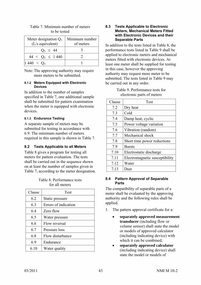
03/2011 NMI M 10-2 43
Table 7. Minimum number of meters to be tested
Meter designation Q3 (L/s equivalent)
Minimum number of meters
Q3 44 3
44 < Q3 1 440 2
1 440 < Q3 1
Note: The approving authority may require more meters to be submitted.
8.1.2 Meters Equipped with Electronic Devices
In addition to the number of samples specified in Table 7, one additional sample shall be submitted for pattern examination when the meter is equipped with electronic devices.
8.1.3 Endurance Testing
A separate sample of meters may be submitted for testing in accordance with 6.9. The minimum number of meters required in this sample is shown in Table 7.
8.2 Tests Applicable to all Meters
Table 8 gives a program for testing all meters for pattern evaluation. The tests shall be carried out in the sequence shown on at least the number of samples given in Table 7, according to the meter designation.
Table 8. Performance tests for all meters
Clause Test
6.2 Static pressure
6.3 Errors of indication
6.4 Zero flow
6.5 Water pressure
6.6 Flow reversal
6.7 Pressure loss
6.8 Flow disturbance
6.9 Endurance
6.10 Water quality
8.3 Tests Applicable to Electronic Meters, Mechanical Meters Fitted with Electronic Devices and their Separable Parts
In addition to the tests listed in Table 8, the performance tests listed in Table 9 shall be applied to electronic meters and mechanical meters fitted with electronic devices. At least one meter shall be supplied for testing in this case, however the approving authority may request more meter to be submitted. The tests listed in Table 9 may be carried out in any order.
Table 9. Performance tests for electronic parts of meters
Clause Test 7.2 Dry heat 7.3 Cold 7.4 Damp heat, cyclic 7.5 Power voltage variation 7.6 Vibration (random) 7.7 Mechanical shock 7.8 Short time power reductions 7.9 Bursts 7.10 Electrostatic discharge 7.11 Electromagnetic susceptibility 7.12 Water 7.13 Dust
8.4 Pattern Approval of Separable
Parts
The compatibility of separable parts of a meter shall be evaluated by the approving authority and the following rules shall be applied.
1. The pattern approval certificate for a:
separately approved measurement transducer (including flow or volume sensor) shall state the model or models of approved calculator (including indicating device) with which it can be combined;
separately approved calculator (including indicating device) shall state the model or models of

03/2011 NMI M 10-2 44
approved measurement transducer (including flow or volume sensor) with which it can be combined;
combined meter shall state which model or models of approved calculator (including indicating device) and approved measurement transducer (including flow or volume sensor) which can be combined.
2. The MPEs for the calculator (including indicating device) or measurement transducer (including flow or volume sensor) shall be declared by the manufacturer when it is submitted for pattern examination.
3. The arithmetic sum of the MPEs of an approved calculator (including indicating device) and an approved measurement transducer (including flow or volume sensor) shall not exceed the MPEs for a complete meter (NMI M 10-1, 3.2).
4. Measurement transducers (including flow or volume sensor) of mechanical meters, mechanical meters fitted with electronic devices and electronic meters, shall be subjected to the applicable performance tests listed in Tables 8 and 9.
5. Calculators (including indicating device) of mechanical meters, mechanical meters fitted with electronic devices and electronic meters, shall be subjected to the applicable performance tests listed in Tables 8 and 9.
6. Wherever possible, the test conditions applied during the pattern evaluation of a complete meter shall be applied to the separable parts of a meter. Where this is not possible for certain test conditions, simulated conditions, of equivalent severity and duration, shall be applied.
7. The performance test requirements of 6 and 7 shall be met where applicable.
8. The results of the pattern evaluation tests of separable parts of a meter shall be declared in a report of similar format to that for a complete meter (see NMI M 10-3).
8.5 Families of Meters
When a family of meters is submitted for pattern approval, the criteria in Annex C shall be applied by NMI in deciding if the meters conform to the definition of ‘a family’ and in selecting which meter sizes are to be tested.
9. TESTS FOR INITIAL VERIFICATION
In general, only meters which have been approved either as complete meters or as separately approved, calculator (including indicating device) and measurement transducer (including flow or volume sensor), and subsequently assembled into a combined meter shall be eligible for initial verification.
However, NMI may allow substitution in service of separately approved calculators (including indicating device) and measurement transducers (including flow or volume sensor), if it has been proven during pattern evaluation that such substitutions will not result in the combined MPEs exceeding the respective MPEs for a complete meter.
Any special requirements for initial verification testing which have been detailed in the pattern approval certificate, shall be applied.
9.1 Water Meter
9.1.1 Object of Test
To verify that the relative errors of indication of the meter are within the MPEs in 3.2 of NMI M 10-1.
9.1.2 Preparation
The errors of indication of the meter shall be measured using equipment and principles described in 6.1 and 6.3.

03/2011 NMI M 10-2 45
9.1.3 Test Procedure
1. Install the meters for testing either singly or in series.
2. Apply the procedures given in 6.3.
3. Ensure that there is no significant interaction between meters installed in series.
4. Ensure that outlet pressure of any meter is not less than 0.03 MPa (0.3 bar).
5. Ensure that working water temperature range is: 20 10°C.
6. Ensure that all other influence factors are held within the rated operating conditions of the meter.
7. Unless alternative flowrates are specified in the pattern approval certificate, measure the errors of indication at the following flowrates:
a) between Q1 and 1.1 Q1;
b) between 0.5 Q3 and 0.6 Q3;
c) between 0.9 Q3 and Q3.
8. Calculate the error of indication, in accordance with Annex A, for each flowrate.
9. Complete test report NMI M 10-3, Example 1.
9.1.4 Acceptance Criteria
1. The errors of indication of the EUT shall not exceed the MPEs in 3.2 of NMI M 10-1.
2. If all the errors of indication of the meter have the same sign, at least one of these errors shall not exceed half the MPE. In all cases this requirement shall be applied equitably with respect to the water supplier and the consumer (NMI M 10-1, 3.4.3 paragraphs 3 and 7).
9.2 Separable Parts
9.2.1 Object of Test
To verify that the errors of indication of the measurement transducer (including volume or flow sensor) or the calculator (including indicating device) are within the MPEs stated in the pattern approval certificate.
Measurement transducers (including flow or volume sensors) shall be subjected to the initial verification tests listed in 9.1.
Calculators (including indicating devices) shall be subjected to the initial verification tests listed in 9.1.
9.2.2 Preparation
The errors of indication of separable approved parts of a meter shall be measured using equipment and principles described in 6.1 and the performance test requirements of 6.3 shall be met where applicable.
Where possible, the test conditions applied during the pattern evaluation of a complete meter shall be applied to the separable parts of a meter. Where this is not possible for certain test conditions, simulated conditions, of equivalent characteristics, severity and duration shall be applied.
9.2.3 Test Procedure
The test procedure in 9.1.3 shall be followed except where simulated testing is necessary.
Complete test report NMI M 10-3, Example 2 and/or Example 3.
9.2.4 Acceptance Criteria
The errors of indication of separable parts of the meter shall not exceed the MPEs stated in the pattern approval certificate.
10. PRESENTATION OF RESULTS
10.1 Object of Reports
To record and present the work carried out by the testing laboratory, including the results of the tests and examinations and all relevant information accurately, clearly and unambiguously, in the format given in NMI M 10-3 [2].
03/2011 NMI M 10-2 46
10.2 Identification and Test Data to be Included in Records
10.2.1 Pattern Evaluation
The record of a pattern evaluation shall contain:
(a) a precise identification of the test laboratory and the meter tested;
(b) the calibration history of all instrumentation and measuring devices used for the tests;
(c) exact details of the conditions during which the various tests were carried out, including any specific test conditions advised by the manufacturer;
(d) the results and conclusions of the tests, as required in this document;
(e) The limitations applying to the application of separately approved measurement transducers and calculators.
10.2.2 Initial Verification
The record of an initial verification or subsequent verification test for an individual meter shall include as a minimum:
(a) identification of testing laboratory, i.e. name and address;
(b) identification of meter tested: name and address of the
manufacturer or the trademark used; the meter designation Q3; the ratios Q3/Q1; the maximum pressure loss (and
corresponding flowrate); year of manufacture and the serial
number of the meter tested; type or model;
(c) the results and conclusions of the tests.

03/2011 NMI M 10-2 47
ANNEX A. CALCULATING THE RELATIVE ERROR OF INDICATION (MANDATORY)
A.1 General This Annex defines the formulae to be applied during pattern approval and verification tests, when calculating the error of indication of a: complete meter; separable calculator (including
indicating device); separable measurement transducer
(including flow or volume sensor).
A.2 Error of Indication When either a measurement transducer (including flow or volume sensor) or a calculator (including indicating device) of a meter is submitted for separable pattern approval, error of indication measurements are carried out only on these separable parts of the meter.
For a measurement transducer (including flow or volume sensor), the output signal (pulse, current, voltage or encoded) is measured by a suitable instrument.
For the calculator (including indicating device), the characteristics of simulated input signals (pulse, current, voltage or encoded) should replicate those of the measurement transducer (including flow or volume sensor).
The error of indication of the EUT is calculated according to what is considered to be the true value of the actual volume added during a test, compared with the equivalent volume of either the simulated input signal to the calculator (including indicating device), or the actual output signal from the measurement transducer (including flow or volume sensor), measured during the same test period.
Unless exempted by the metrological authority, a measurement transducer (including flow or volume sensor) and a compatible calculator (including indicating device) have separate pattern approvals, and must be tested together as a combined meter during initial and subsequent
verification (see 9). Therefore, the calculation for the error of indication is the same as for a complete meter.
A.3 Relative Error of Indication of a Complete Meter
Em(i) = [ (Vi – Va) / Va ] 100 (%)
Em(i) relative error of indication of a complete meter at a flowrate, i (where i = 1, 2, ... n)
Va actual (or simulated) volume passed, during the test period, Dt (m3 or kL)
Vi volume added to (or subtracted from) the indicating device, during the test period, Dt (m
3 or kL)
A.4 Relative Error of Indication of a Combined Meter
Treat as a complete meter (see A.3).
A.5 Relative Error of Indication of a Calculator (Including Indicating Device) (Ec(i))
Ec(i) = [ (Vi – Va) / Va ] 100 (%)
Ec(i) relative error of indication of a calculator (including indicating device) at a flowrate, i (where i = 1, 2, ... n)
(a) When tested with a simulated pulse input signal
Va = Cp Tp, the water volume equivalent to the total number of volume pulses injected into the indicating device during the test period, Dt (m
3 or kL) Cp constant equating a nominal volume of
water to each pulse (m3/pulse or kL/pulse) Tp total number of volume pulses injected
during the test period, Dt (pulses) Vi volume registered by the indicating
device, added during the test period, Dt (m3 or kL)
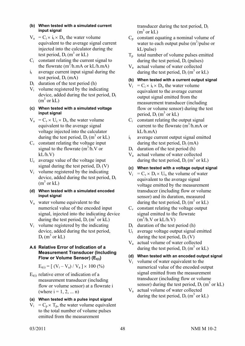
03/2011 NMI M 10-2 48
(b) When tested with a simulated current input signal
Va = Ci it Dt, the water volume equivalent to the average signal current injected into the calculator during the test period, Dt (m
3 or kL) Ci constant relating the current signal to
the flowrate (m3/h.mA or kL/h.mA) it average current input signal during the
test period, Dt (mA) Dt duration of the test period (h) Vi volume registered by the indicating
device, added during the test period, Dt (m3 or kL)
(c) When tested with a simulated voltage input signal
Va = Cv Uc Dt, the water volume equivalent to the average signal voltage injected into the calculator during the test period, Dt (m
3 or kL) Cv constant relating the voltage input
signal to the flowrate (m3/h.V or kL/h.V)
Uc average value of the voltage input signal during the test period, Dt (V)
Vi volume registered by the indicating device, added during the test period, Dt (m3 or kL)
(d) When tested with a simulated encoded input signal
Va water volume equivalent to the numerical value of the encoded input signal, injected into the indicating device during the test period, Dt (m
3 or kL) Vi volume registered by the indicating
device, added during the test period, Dt (m
3 or kL)
A.6 Relative Error of Indication of a Measurement Transducer (Including Flow or Volume Sensor) (Et(i))
Et(i) = [ (Vi – Va) / Va ] 100 (%)
Et(i) relative error of indication of a measurement transducer (including flow or volume sensor) at a flowrate i (where i = 1, 2, ... n)
(a) When tested with a pulse input signal
Vi = Cp Tp, the water volume equivalent to the total number of volume pulses emitted from the measurement
transducer during the test period, Dt (m3 or kL)
Cp constant equating a nominal volume of water to each output pulse (m3/pulse or kL/pulse)
Tp total number of volume pulses emitted during the test period, Dt (pulses)
Va actual volume of water collected during the test period, Dt (m
3 or kL)
(b) When tested with a current output signal
Vi = Ci it Dt, the water volume equivalent to the average current output signal emitted from the measurement transducer (including flow or volume sensor) during the test period, Dt (m
3 or kL) Ci constant relating the output signal
current to the flowrate (m3/h.mA or kL/h.mA)
it average current output signal emitted during the test period, Dt (mA)
Dt duration of the test period (h) Va actual volume of water collected
during the test period, Dt (m3 or kL)
(c) When tested with a voltage output signal
Vi = Cv Dt Ut, the volume of water equivalent to the average signal voltage emitted by the measurement transducer (including flow or volume sensor) and its duration, measured during the test period, Dt (m
3 or kL) Cv constant relating the voltage output
signal emitted to the flowrate (m3/h.V or kL/h.V)
Dt duration of the test period (h) Ut average voltage output signal emitted
during the test period, Dt (V) Va actual volume of water collected
during the test period, Dt (m3 or kL)
(d) When tested with an encoded output signal Vi volume of water equivalent to the
numerical value of the encoded output signal emitted from the measurement transducer (including flow or volume sensor) during the test period, Dt (m
3 or kL) Va actual volume of water collected
during the test period, Dt (m3 or kL)
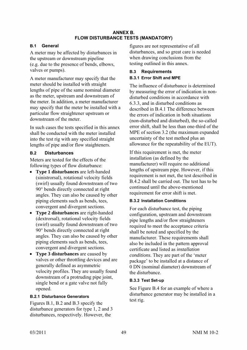
03/2011 NMI M 10-2 49
ANNEX B. FLOW DISTURBANCE TESTS (MANDATORY)
B.1 General
A meter may be affected by disturbances in the upstream or downstream pipeline (e.g. due to the presence of bends, elbows, valves or pumps).
A meter manufacturer may specify that the meter should be installed with straight lengths of pipe of the same nominal diameter as the meter, upstream and downstream of the meter. In addition, a meter manufacturer may specify that the meter be installed with a particular flow straightener upstream or downstream of the meter.
In such cases the tests specified in this annex shall be conducted with the meter installed into the test rig with any specified straight lengths of pipe and/or flow staighteners.
B.2 Disturbances
Meters are tested for the effects of the following types of flow disturbance: Type 1 disturbances are left-handed
(sinistrorsal), rotational velocity fields (swirl) usually found downstream of two 90° bends directly connected at right angles. They can also be caused by other piping elements such as bends, tees, convergent and divergent sections.
Type 2 disturbances are right-handed (dextrorsal), rotational velocity fields (swirl) usually found downstream of two 90° bends directly connected at right angles. They can also be caused by other piping elements such as bends, tees, convergent and divergent sections.
Type 3 disturbances are caused by valves or other throttling devices and are generally defined as asymmetric velocity profiles. They are usually found downstream of a protruding pipe joint, single bend or a gate valve not fully opened.
B.2.1 Disturbance Generators
Figures B.1, B.2 and B.3 specify the disturbance generators for type 1, 2 and 3 disturbances, respectively. However, the
figures are not representative of all disturbances, and so great care is needed when drawing conclusions from the testing outlined in this annex.
B.3 Requirements B.3.1 Error Shift and MPE
The influence of disturbance is determined by measuring the error of indication in non-disturbed conditions in accordance with 6.3.3, and in disturbed conditions as described in B.4.1 The difference between the errors of indication in both situations (non-disturbed and disturbed), the so-called error shift, shall be less than one-third of the MPE of section 3.2 (the maximum expanded uncertainty of the test method plus an allowance for the repeatability of the EUT).
If this requirement is met, the meter installation (as defined by the manufacturer) will require no additional lengths of upstream pipe. However, if this requirement is not met, the test described in B.4.2 shall be carried out. The test has to be continued until the above-mentioned requirement for error shift is met.
B.3.2 Installation Conditions
For each disturbance test, the piping configuration, upstream and downstream pipe lengths and/or flow straighteners required to meet the acceptance criteria shall be noted and specified by the manufacturer. These requirements shall also be included in the pattern approval certificate and listed as installation conditions. They are part of the ‘meter package’ to be installed at a distance of 0 DN (nominal diameter) downstream of the disturbance.
B.3.3 Test Set-up
See Figure B.4 for an example of where a disturbance generator may be installed in a test rig.
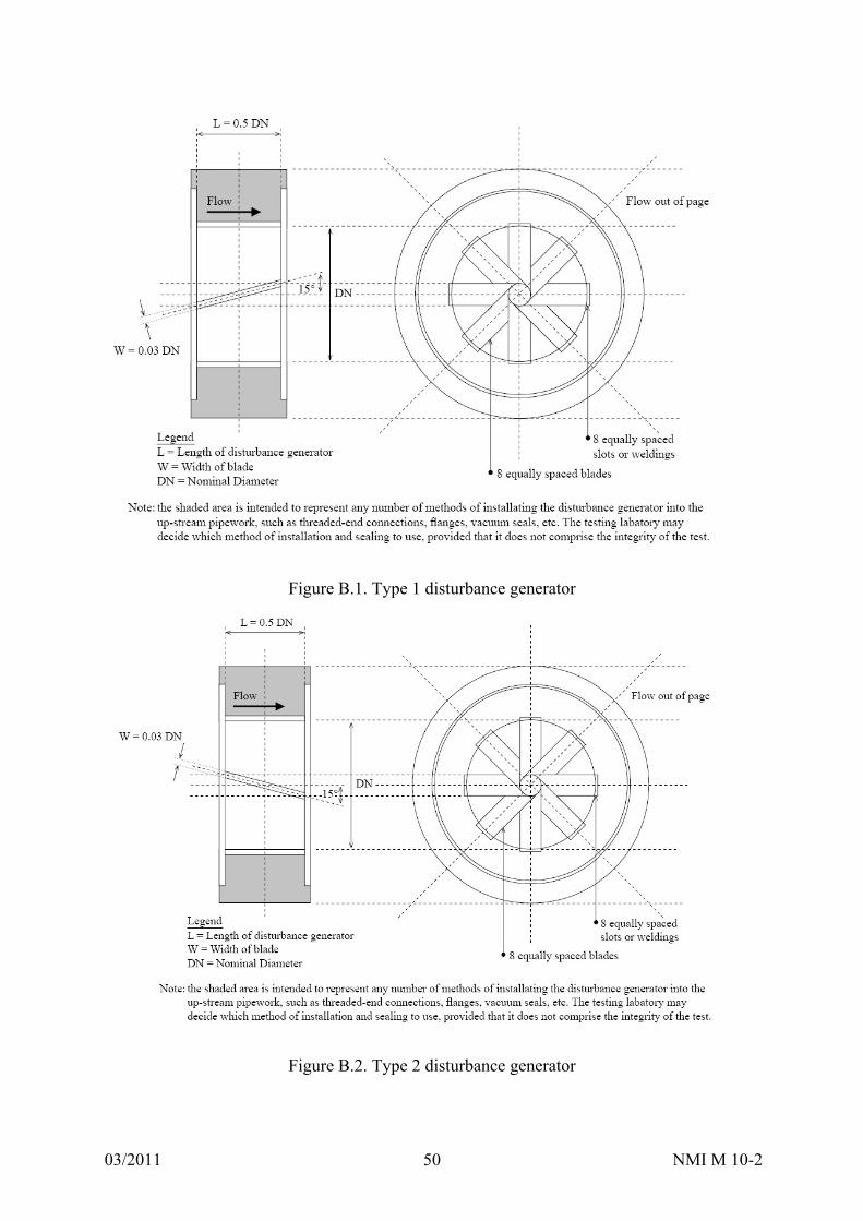
03/2011 NMI M 10-2 50
Figure B.1. Type 1 disturbance generator
Figure B.2. Type 2 disturbance generator
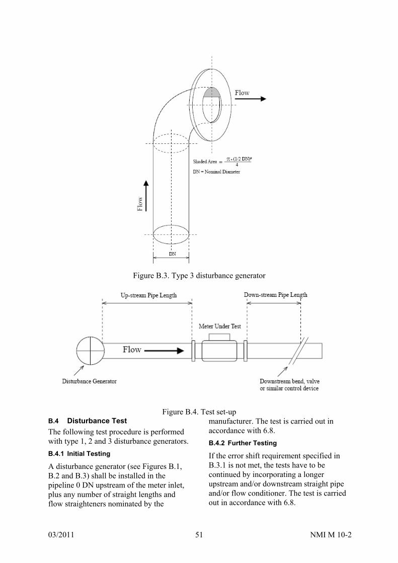
03/2011 NMI M 10-2 51
Figure B.3. Type 3 disturbance generator
Figure B.4. Test set-up
B.4 Disturbance Test
The following test procedure is performed with type 1, 2 and 3 disturbance generators.
B.4.1 Initial Testing
A disturbance generator (see Figures B.1, B.2 and B.3) shall be installed in the pipeline 0 DN upstream of the meter inlet, plus any number of straight lengths and flow straighteners nominated by the
manufacturer. The test is carried out in accordance with 6.8.
B.4.2 Further Testing
If the error shift requirement specified in B.3.1 is not met, the tests have to be continued by incorporating a longer upstream and/or downstream straight pipe and/or flow conditioner. The test is carried out in accordance with 6.8.

03/2011 NMI M 10-2 52
ANNEX C. PATTERN EVALUATION OF A FAMILY OF METERS (MANDATORY)
C.1 Families of Meters
This annex describes the criteria to be applied by NMI in deciding if a group of meters can be considered from the same family for pattern approval purposes, where only selected meter sizes are to be tested.
C.2 Definition
A family of meters is a group of meters of different sizes and/or different flowrates, in which all the meters shall have the following characteristics: the same manufacturer; geometric similarity of the wetted parts; the same metering principle; the same ratios Q3/ Q1; the same electronic device for each meter
size; a similar standard of design and
component assembly; the same materials for those components
that are critical to the performance of the meter;
the same installation requirements relative to the meter size, e.g. 10 DN of straight pipe upstream of the meter and 5 DN of straight pipe downstream of the meter.
C.3 Meter Selection
When considering which sizes of a family of meters should be tested, the following rules shall be followed: NMI shall declare the reasons for
including and omitting particular meter sizes from testing.
The smallest meter in any family of meters shall always be tested.
Meters which have the most extreme operating parameters within a family, shall be considered for testing, e.g. the largest flowrate range, the highest peripheral (tip) speed of moving parts etc.
If practical, the largest meter in any family of meters should always be tested. However, if the largest meter is not tested, then any meter having Q3 > 2 × Q3 of the largest meter tested, shall not be approved as part of a family.
Endurance tests shall be applied to meters where the highest wear is expected.
For meters with no moving parts in the measurement transducer, the smallest size shall be selected for endurance tests.
All performance tests relating to influence quantities and disturbances shall be carried out on one size from a family of meters.
For water quality tests, the smallest size of meter shall be selected for testing.
C.4 Example
By way of example, the family of meters specified in Table C.1 is submitted for pattern approval.
Table C.1
Nominal diameter (mm)
Q3 (L/s)
Is testing required?
50 10 Yes
80 25 No
100 40 No
150 88 Yes
200 157 No
250 245 No
300 353 Yes
Table C.1 indicates the nominal diameter and corresponding maximum continuous flowrate (Q3) for which, the manufacturer has decided to seek approval. Table C.1 also indicates whether that size of meter is required to be submitted for pattern approval testing.
NMI may require additional sizes to be submitted for testing in addition to those indicated.
For some tests, i.e. endurance testing and water quality testing, only one size of meter is required to be tested. In the case of an electromagnetic meter, only the smallest size would be required to be tested. However for most other tests, other meter sizes are required to be submitted for testing.
In the example given in Table C.1, if it was not possible to perform testing on larger sizes of meters with the same family (due to laboratory limitations, for example), the approved pattern could still be extended to larger meter sizes within that family.
In this case the pattern approval could be extended to included meters of that family with a maximum continuous flowrate of up to 706 L/s (being 2 × 353 L/s).
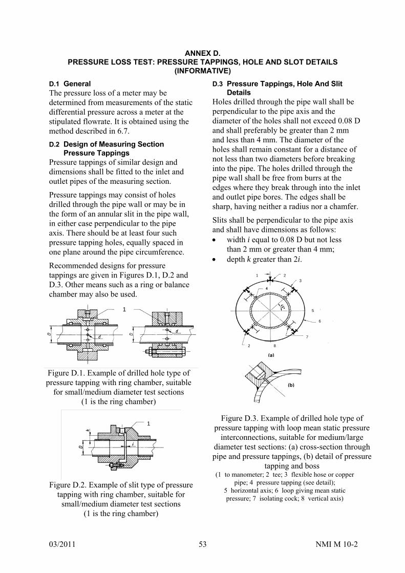
03/2011 NMI M 10-2 53
ANNEX D. PRESSURE LOSS TEST: PRESSURE TAPPINGS, HOLE AND SLOT DETAILS
(INFORMATIVE)
D.1 General The pressure loss of a meter may be determined from measurements of the static differential pressure across a meter at the stipulated flowrate. It is obtained using the method described in 6.7.
D.2 Design of Measuring Section Pressure Tappings
Pressure tappings of similar design and dimensions shall be fitted to the inlet and outlet pipes of the measuring section.
Pressure tappings may consist of holes drilled through the pipe wall or may be in the form of an annular slit in the pipe wall, in either case perpendicular to the pipe axis. There should be at least four such pressure tapping holes, equally spaced in one plane around the pipe circumference.
Recommended designs for pressure tappings are given in Figures D.1, D.2 and D.3. Other means such as a ring or balance chamber may also be used.
1
Figure D.1. Example of drilled hole type of pressure tapping with ring chamber, suitable
for small/medium diameter test sections (1 is the ring chamber)
1
Figure D.2. Example of slit type of pressure
tapping with ring chamber, suitable for small/medium diameter test sections
(1 is the ring chamber)
D.3 Pressure Tappings, Hole And Slit Details
Holes drilled through the pipe wall shall be perpendicular to the pipe axis and the diameter of the holes shall not exceed 0.08 D and shall preferably be greater than 2 mm and less than 4 mm. The diameter of the holes shall remain constant for a distance of not less than two diameters before breaking into the pipe. The holes drilled through the pipe wall shall be free from burrs at the edges where they break through into the inlet and outlet pipe bores. The edges shall be sharp, having neither a radius nor a chamfer.
Slits shall be perpendicular to the pipe axis and shall have dimensions as follows: width i equal to 0.08 D but not less
than 2 mm or greater than 4 mm; depth k greater than 2i.
1 2 3
4
5
6
7
8 2
(a)
(b)
Figure D.3. Example of drilled hole type of
pressure tapping with loop mean static pressure interconnections, suitable for medium/large
diameter test sections: (a) cross-section through pipe and pressure tappings, (b) detail of pressure
tapping and boss (1 to manometer; 2 tee; 3 flexible hose or copper
pipe; 4 pressure tapping (see detail); 5 horizontal axis; 6 loop giving mean static pressure; 7 isolating cock; 8 vertical axis)
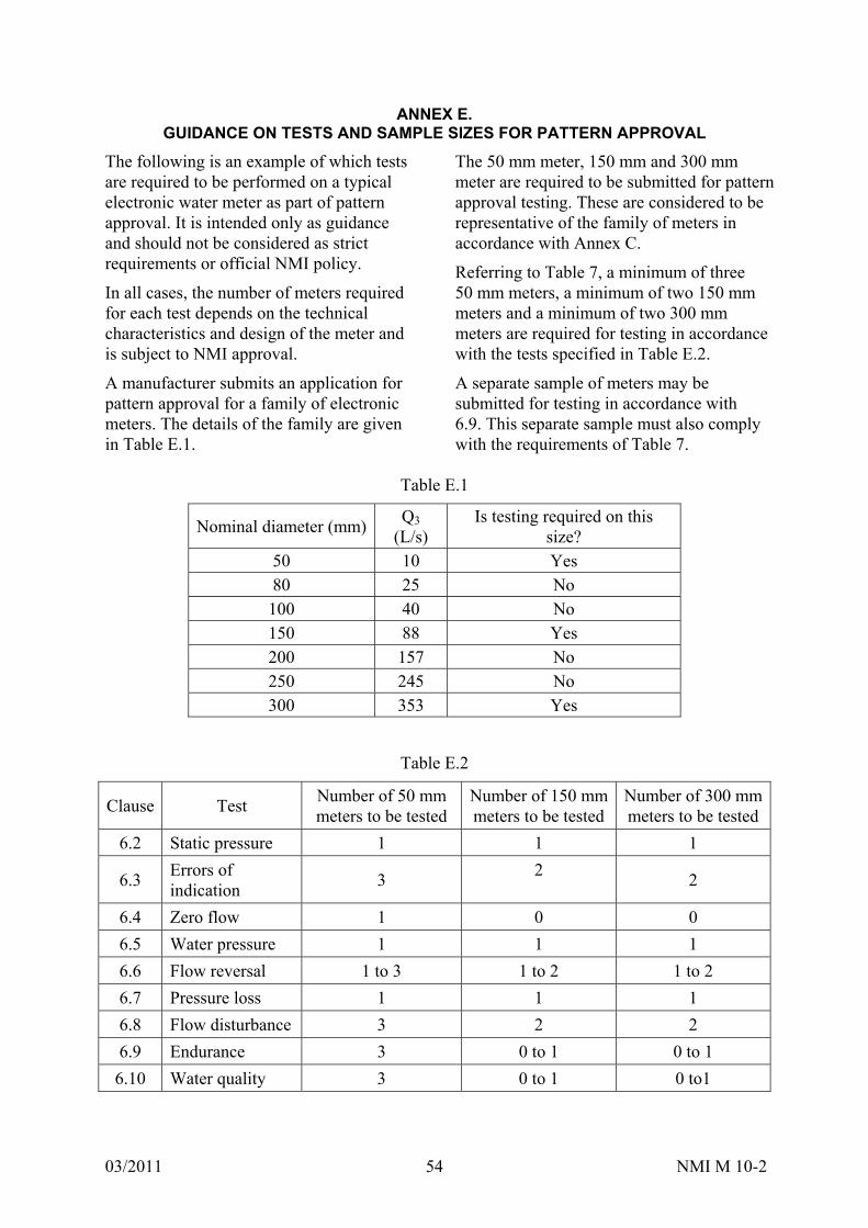
03/2011 NMI M 10-2 54
ANNEX E. GUIDANCE ON TESTS AND SAMPLE SIZES FOR PATTERN APPROVAL
The following is an example of which tests are required to be performed on a typical electronic water meter as part of pattern approval. It is intended only as guidance and should not be considered as strict requirements or official NMI policy.
In all cases, the number of meters required for each test depends on the technical characteristics and design of the meter and is subject to NMI approval.
A manufacturer submits an application for pattern approval for a family of electronic meters. The details of the family are given in Table E.1.
The 50 mm meter, 150 mm and 300 mm meter are required to be submitted for pattern approval testing. These are considered to be representative of the family of meters in accordance with Annex C.
Referring to Table 7, a minimum of three 50 mm meters, a minimum of two 150 mm meters and a minimum of two 300 mm meters are required for testing in accordance with the tests specified in Table E.2.
A separate sample of meters may be submitted for testing in accordance with 6.9. This separate sample must also comply with the requirements of Table 7.
Table E.1
Nominal diameter (mm)Q3
(L/s) Is testing required on this
size? 50 10 Yes 80 25 No 100 40 No 150 88 Yes 200 157 No 250 245 No 300 353 Yes
Table E.2
Clause Test Number of 50 mm meters to be tested
Number of 150 mm meters to be tested
Number of 300 mm meters to be tested
6.2 Static pressure 1 1 1
6.3 Errors of indication
3 2
2
6.4 Zero flow 1 0 0
6.5 Water pressure 1 1 1
6.6 Flow reversal 1 to 3 1 to 2 1 to 2
6.7 Pressure loss 1 1 1
6.8 Flow disturbance 3 2 2
6.9 Endurance 3 0 to 1 0 to 1
6.10 Water quality 3 0 to 1 0 to1

03/2011 NMI M 10-2 55
As per clause 8.1.2, a single meter must also be submitted for testing in accordance with 7.
The meter is a fully self-contained unit powered by a non-rechargeable battery and the manufacturer has specified that the meter is to be approved as environmental class O. Therefore, a single sample of the 50 mm meter must also be submitted for testing in accordance with Table E.3.
Table E.4 indicates the optional testing that may be performed at the discretion of the manufacturer.
The numbers of meters required to be tested is entirely dependent upon the intended scope of the approval and is subject to agreement between the manufacturer and NMI.
Table E.3
Clause Test Number of 50 mm
meters to be tested
7.2 Dry heat 1
7.3 Cold 1
7.4 Damp heat, cyclic 1
7.5 Power voltage variation 1
7.6 Vibration (random) 0
7.7 Mechanical shock 0
7.8 Short time power reductions 0
7.9 Bursts 1
7.10 Electrostatic discharge 1
7.11 Electromagnetic susceptibility
1
7.12 Water 1
7.13 Dust 1
Table E.4
Clause Test Number of 50 mm meters to be tested
Number of 300 mmmeters to be tested
6.11 Meters used in open channel emplacements
0 to 3 0 to 2
6.12 Installation tests 0 to 3 0 to 2
6.13 Test for cartridge meters and meters with interchangeable inserts
0 to 5 0 to 5
6.14 Maintenance tests 0 to 3 0 to 2

03/2011 NMI M 10-2 56
BIBLIOGRAPHY
[1] NMI M 10-1 (2008) Meters Intended for the Metering of Water in Full Flowing Pipes. Part 1: Metrological and Technical Requirements
[2] NMI M 10-3 (2008) Meters Intended for the Metering of Water in Full Flowing Pipes. Part 3: Model Test Report
[3] IEC 60068-1 (1991) Environmental Testing. Part 1: General and Guidance. Also refer to amendment 1 (1992). The equivalent Australian standard is AS 60068.1 (2003)
[4] Guide to the Expression of Uncertainty in Measurement (1995) BIPM, IEC, IFCC, ISO, IUPAC, IUPAP and OIML
[5] NMI P 106 (2007) Approval and Certification Procedures for Measuring Instruments for Trade Use
[6] National Framework for Non-urban Water Metering (policy paper, final draft) Department of the Environment, Water, Heritage and the Arts (2008) http://www.environment.gov.au/water/ publications/agriculture/ris-metering-non-urban.html
[7] IEC 61000-2-2 (2002) Electromagnetic Compatibility. Part 2-2: Environment — Compatibility Levels for Low-frequency Conducted Disturbances and Signalling in Public Low-voltage Power Supply Systems. The equivalent Australian standard is AS/NZS 61000.2.2 (2003)
[8] IEC 60068-3-1 (1974) Basic Environmental Testing Procedures. Part 3: Background Information. Section 1 — Cold and Dry Heat Tests. Also refer to first supplement IEC 60068-3-1A (1978). The equivalent Australian standard is AS 60068.3.1 (2003)
[9] IEC 60068-2-1 (2007) Environmental Testing. Part 2-1: Tests — Test A: Cold. Clause 5.3 Test Ad: Cold for Heat-dissipating Specimens with Gradual Change of Temperature that are Powered after Initial Temperature Stabilisation
[10] IEC 60068-2-30 (2005) Environmental Testing. Part 2-30: Tests — Test Dd: Damp Heat, Cyclic (12 h + 12 h Cycle)
[11] IEC 60068-3-4 (2001) Environmental Testing. Part 3-4: Supporting Documentation and Guidance — Damp Heat Tests. The equivalent Australian standard is AS 60068.3.4 (2003)
[12] IEC 61000-4-11 (2004) Electromagnetic Compatibility. Part 4-11: Testing and Measurement Techniques — Voltage Dips, Short Interruptions and Voltage Variations Immunity Tests. The equivalent Australian standard is AS/NZS 61000.4.11 (2005)
[13] IEC 61000-2-1 (1990) Electromagnetic Compatibility. Part 2: Environment — Section 1: Description of the environment — Electromagnetic Environment for Low-frequency Conducted Disturbances and Signalling in Public Power Supply Systems
[14] IEC 61000-2-2 (2002) Electromagnetic Compatibility. Part 2-2: Environment — Compatibility Levels for Low-frequency Conducted Disturbances and Signalling in Public Low-voltage Power Supply Systems. The equivalent Australian standard is AS/NZS 61000.2.2 (2003)
[15] IEC 61000-4-1 (2006) Electromagnetic Compatibility. Part 4-1: Testing and Measurement Techniques — Overview of IEC 61000-4 Series. The equivalent Australian standard is AS/NZS 61000.4.1 (2006)
[16] IEC 60654-2 (1979) Operating Conditions for Industrial-process Measurement and Control Equipment. Part 2: Power. Also refer to amendment 1 (1992)
[17] IEC 61000-2-12 (2002) Electromagnetic Compatibility. Part 2-12: Environment — Compatibility Levels for Low-frequency Conducted Disturbances and Signalling in Public medium-voltage Power Supply Systems. The equivalent Australian standard is AS/NZS 61000.2.12 (2003)
03/2011 NMI M 10-2 57
[18] IEC 61000-4-5 (2005) Electromagnetic Compatibility. Part 4.5: Testing and Measurement Techniques — Surge Immunity Test. The equivalent Australian standard is AS 61000.4.5 (2006)
[19] IEC 60068-2-64 (1993) Environmental Testing. Part 2: Test Methods. Test Fh: Vibration, Broad-band Random (Digital Control) and Guidance. Also refer to corrigendum 1 (1993). The equivalent Australian standard is AS 60068.2.64 (2003)
[20] IEC 60068-2-47 (2005) Environmental Testing. Part 2-47: Test — Mounting of Specimens for Vibration, Impact and Similar Dynamic Tests
[21] IEC 60068-2-31 (1969) Basic Environmental Testing Procedures. Part 2: Tests. Test Ec: Drop and Topple, Primarily for Equipment-type Specimens. Also refer to amendment 1 (1982). The equivalent Australian standard is AS 60068.2.31 (2003)
[22] IEC 61000-4-4 (2004) Electromagnetic Compatibility. Part 4-4: Testing and Measurement Techniques — Electrical Fast Transient/Burst Immunity Test. Also refer to corrigendum 1 (2006). The equivalent Australian standard is AS/NZS 61000.4.1 (2006)
[23] IEC 61000-4-2 (2001) Electromagnetic Compatibility. Part 4-2: Testing and Measurement Techniques — Electrostatic Discharge Immunity Test. The equivalent Australian standard is AS/NZS 61000.4.2 (2002)
[24] IEC 61000-4-3 (2006) Electromagnetic Compatibility. Part 4-3: Testing and Measurement Techniques — Radiated, Radio-frequency, Electromagnetic Field Immunity Test. The equivalent Australian standard is AS/NZS 61000.4.3 (2006)
[25] IEC 61000-4-20 (2007) Electromagnetic Compatibility. Part 4-20: Testing and Measurement Techniques — Emission and Immunity Testing in Transverse Electromagnetic Waveguides
[26] IEC 60068-2-18 (2000) Environmental Testing. Part 2-18: Tests — Test R and Guidance: Water. The equivalent Australian standard is AS 60068.2.18 (2003)
[27] IEC 60512-14-7 (1997) Electromechanical Components for Electronic Equipment — Basic Testing Procedures and Measuring Methods. Part 14-7: Sealing Tests — Test 14g: Impacting Water
[28] IEC 60529 (2004) Degrees of Protection Provided by Enclosures (IP Code)
[29] IEC 60512-11-8 (1995) Electromechanical Components for Electronic Equipment — Basic Testing Procedures and Measuring Methods. Part 11-8: Climatic Tests — Test 11h — Sand and Dust
[30] IEC 60721-2-5 (1991) Classification of Environmental Conditions — Part 2-5: Environmental Conditions Appearing in Nature — Dust, Sand, Salt Mist
[31] OIML D 11 (2004) General Requirements for Electronic Measuring Instruments
[32] IEC 60068-2-68 (1994) Environmental Testing. Part 2-68: Tests — Test L: Dust and Sand. The equivalent Australian standard is AS 60068.2.68 (2003)