Embed Size (px)
Citation preview
Rogessor Engineering (PVT) Ltd.
Dulith Kasun (Network Supportive Specialist) Page 1
NMS (Network Monitoring System)
Required Documents & Tools
Lap Top
Ethernet Cable
USB 2 Serial Cable with Male/Female Adapter
IP Database
Labling
Ethernet Tester
Cat5e Patch Codes
Cat 5e Cable Role
NMS Cables
Flat Screw
Crimping Tool
What are the Devices used in NMS….?
IDU
2.0 version of AWY
2.1 old version of AWY
2.1 new version of AWY
MPR
MPT
MXC
Routers
Cisco routers
7705 SAR-8 routers
7705 SAR-F routers
Rogessor Engineering (PVT) Ltd.
Dulith Kasun (Network Supportive Specialist) Page 2
What are the softwares required for NMS…?
Alcatel 1320 to login to AWY 2.0 old version of AWY
AWY_CT software to login to 2.1 version of AWY
NEO_Web EML software to login to MPR & MPT.
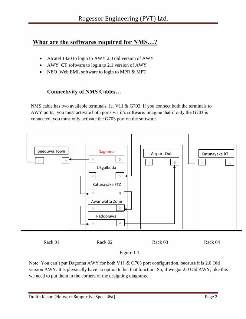
Connectivity of NMS Cables…
NMS cable has two available terminals. Ie. V11 & G703. If you connect both the terminals to
AWY ports, you must activate both ports via it’s software. Imagine that if only the G703 is
connected, you must only activate the G703 port on the software.
Rack 01 Rack 02 Rack 03 Rack 04
Figure 1.1
Note: You can’t put Dagonna AWY for both V11 & G703 port configuration, because it is 2.0 Old
version AWY. It is physically have no option to het that function. So, if we got 2.0 Old AWY, like this
we need to put them in the corners of the designing diagrams.
V
V
V
V
V V V G G
Awariwatta Zone
G
Raddoluwa
G
G
Katunayake FTZ
G
Ukgalboda
G V G
Katunayake RT Airport Out Dagonna Seeduwa Town
Rogessor Engineering (PVT) Ltd.
Dulith Kasun (Network Supportive Specialist) Page 3
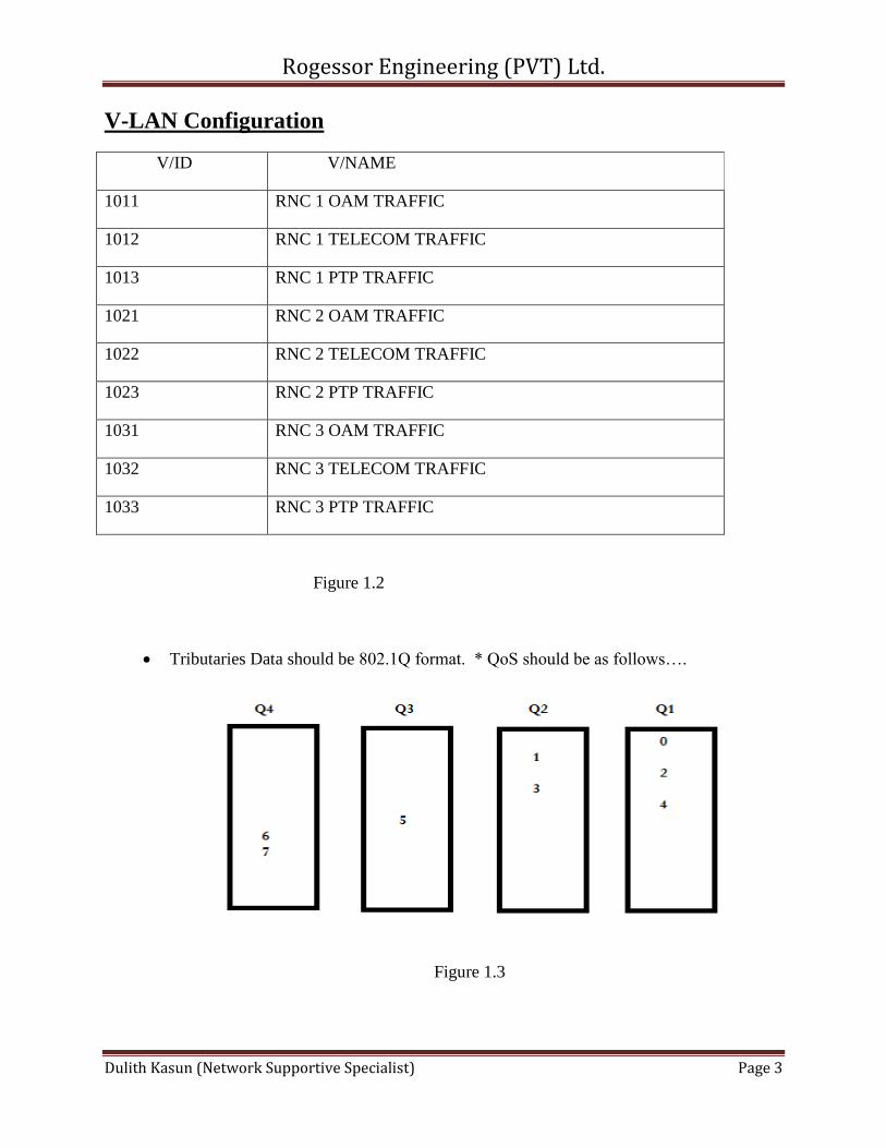
V-LAN Configuration
V/ID V/NAME
1011 RNC 1 OAM TRAFFIC
1012 RNC 1 TELECOM TRAFFIC
1013 RNC 1 PTP TRAFFIC
1021 RNC 2 OAM TRAFFIC
1022 RNC 2 TELECOM TRAFFIC
1023 RNC 2 PTP TRAFFIC
1031 RNC 3 OAM TRAFFIC
1032 RNC 3 TELECOM TRAFFIC
1033 RNC 3 PTP TRAFFIC
Figure 1.2
Tributaries Data should be 802.1Q format. * QoS should be as follows….
Figure 1.3
Rogessor Engineering (PVT) Ltd.
Dulith Kasun (Network Supportive Specialist) Page 4
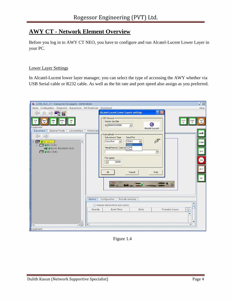
AWY CT - Network Element Overview
Before you log in to AWY CT NEO, you have to configure and run Alcatel-Lucent Lower Layer in
your PC.
Lower Layer Settings
In Alcatel-Lucent lower layer manager, you can select the type of accessing the AWY whether via
USB Serial cable or R232 cable. As well as the bit rate and port speed also assign as you preferred.
Figure 1.4
Rogessor Engineering (PVT) Ltd.
Dulith Kasun (Network Supportive Specialist) Page 5
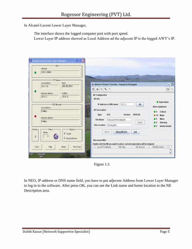
In Alcatel-Lucent Lower Layer Manager,
The interface shows the logged computer port with port speed.
Lower Layer IP address showed as Local Address ad the adjecent IP is the logged AWY’s IP.
Figure 1.5
In NEO, IP address or DNS name field, you have to put adjecent Address from Lower Layer Manager
to log in to the software. After press OK, you can see the Link name and home location in the NE
Description area.
Rogessor Engineering (PVT) Ltd.
Dulith Kasun (Network Supportive Specialist) Page 6
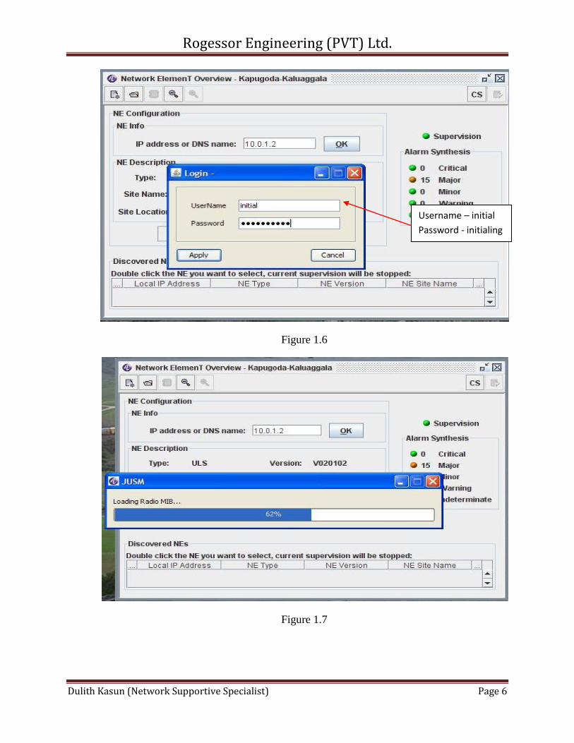
Figure 1.6
Figure 1.7
Username – initial
Password - initialing
Rogessor Engineering (PVT) Ltd.
Dulith Kasun (Network Supportive Specialist) Page 7
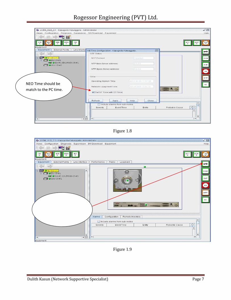
Figure 1.8
Figure 1.9
NEO Time should be
match to the PC time.
To operate NEO,
supervision key should
be Green.
Rogessor Engineering (PVT) Ltd.
Dulith Kasun (Network Supportive Specialist) Page 8
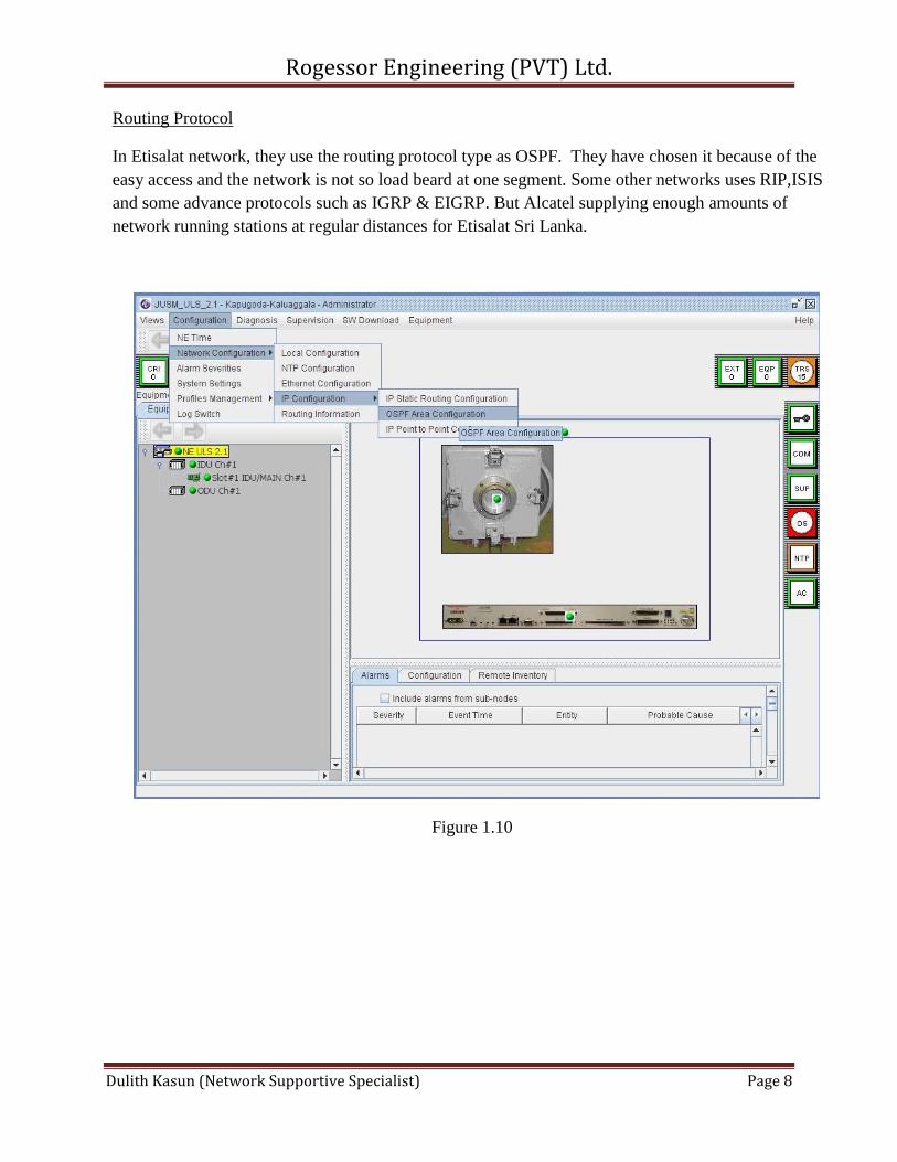
Routing Protocol
In Etisalat network, they use the routing protocol type as OSPF. They have chosen it because of the
easy access and the network is not so load beard at one segment. Some other networks uses RIP,ISIS
and some advance protocols such as IGRP & EIGRP. But Alcatel supplying enough amounts of
network running stations at regular distances for Etisalat Sri Lanka.
Figure 1.10
Rogessor Engineering (PVT) Ltd.
Dulith Kasun (Network Supportive Specialist) Page 9
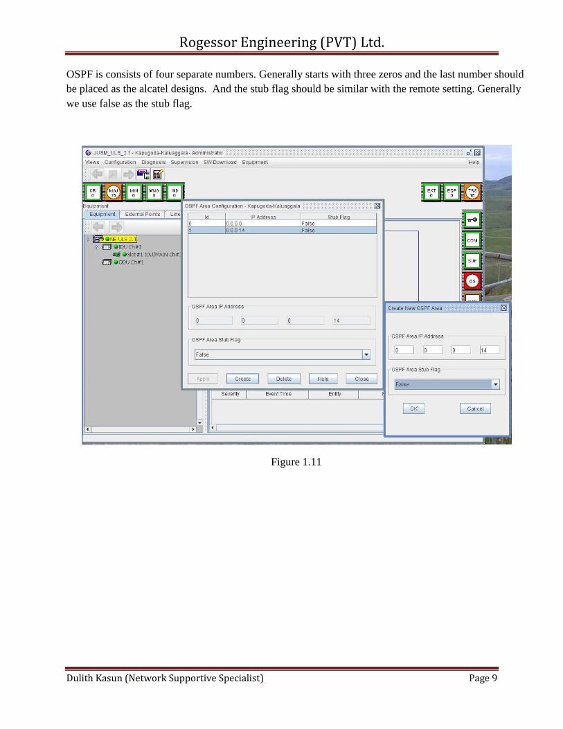
OSPF is consists of four separate numbers. Generally starts with three zeros and the last number should
be placed as the alcatel designs. And the stub flag should be similar with the remote setting. Generally
we use false as the stub flag.
Figure 1.11
Rogessor Engineering (PVT) Ltd.
Dulith Kasun (Network Supportive Specialist) Page 10
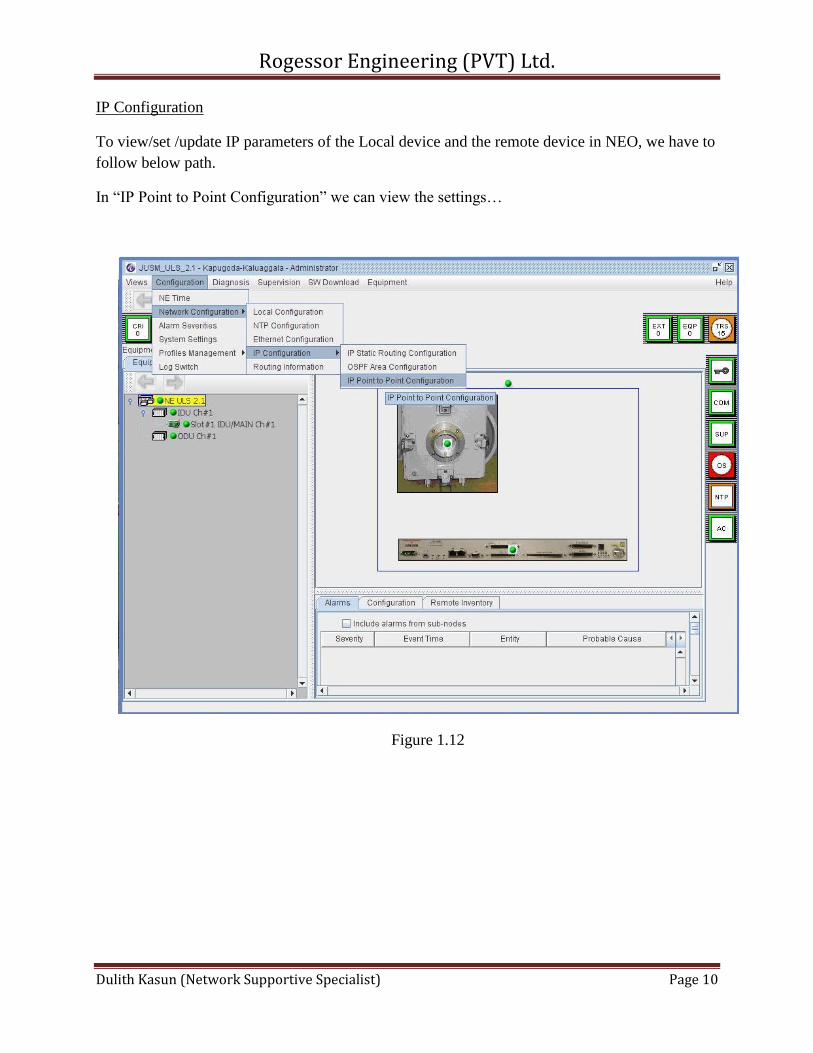
IP Configuration
To view/set /update IP parameters of the Local device and the remote device in NEO, we have to
follow below path.
In “IP Point to Point Configuration” we can view the settings…
Figure 1.12
Rogessor Engineering (PVT) Ltd.
Dulith Kasun (Network Supportive Specialist) Page 11
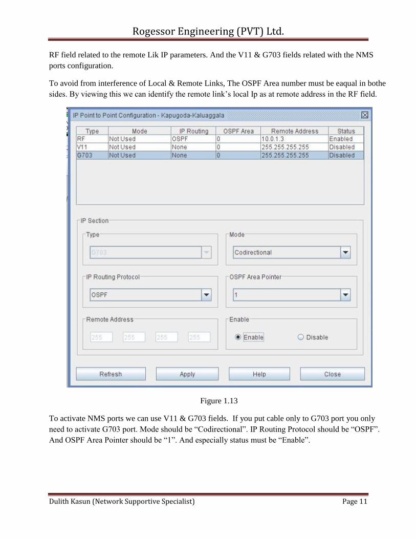
RF field related to the remote Lik IP parameters. And the V11 & G703 fields related with the NMS
ports configuration.
To avoid from interference of Local & Remote Links, The OSPF Area number must be eaqual in bothe
sides. By viewing this we can identify the remote link’s local Ip as at remote address in the RF field.
Figure 1.13
To activate NMS ports we can use V11 & G703 fields. If you put cable only to G703 port you only
need to activate G703 port. Mode should be “Codirectional”. IP Routing Protocol should be “OSPF”.
And OSPF Area Pointer should be “1”. And especially status must be “Enable”.
Rogessor Engineering (PVT) Ltd.
Dulith Kasun (Network Supportive Specialist) Page 12
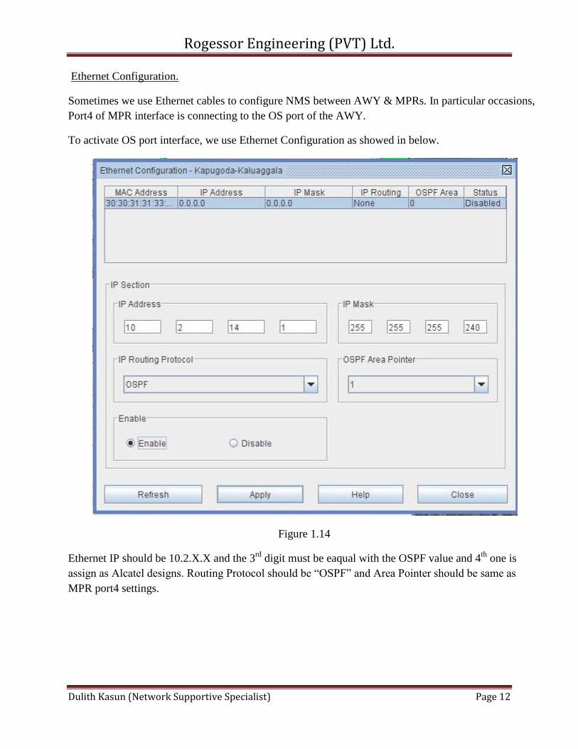
Ethernet Configuration.
Sometimes we use Ethernet cables to configure NMS between AWY & MPRs. In particular occasions,
Port4 of MPR interface is connecting to the OS port of the AWY.
To activate OS port interface, we use Ethernet Configuration as showed in below.
Figure 1.14
Ethernet IP should be 10.2.X.X and the 3rd
digit must be eaqual with the OSPF value and 4th
one is
assign as Alcatel designs. Routing Protocol should be “OSPF” and Area Pointer should be same as
MPR port4 settings.
Rogessor Engineering (PVT) Ltd.
Dulith Kasun (Network Supportive Specialist) Page 13
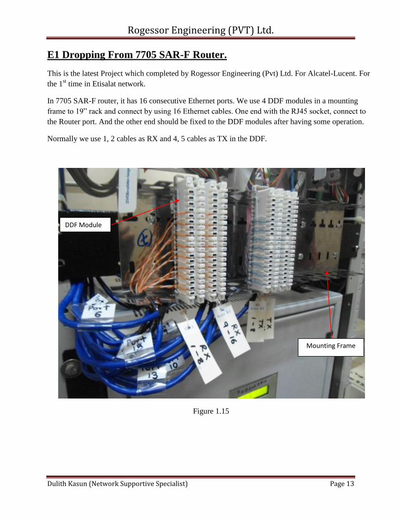
E1 Dropping From 7705 SAR-F Router.
This is the latest Project which completed by Rogessor Engineering (Pvt) Ltd. For Alcatel-Lucent. For
the 1st time in Etisalat network.
In 7705 SAR-F router, it has 16 consecutive Ethernet ports. We use 4 DDF modules in a mounting
frame to 19” rack and connect by using 16 Ethernet cables. One end with the RJ45 socket, connect to
the Router port. And the other end should be fixed to the DDF modules after having some operation.
Normally we use 1, 2 cables as RX and 4, 5 cables as TX in the DDF.
Figure 1.15
DDF Module
Mounting Frame
Rogessor Engineering (PVT) Ltd.
Dulith Kasun (Network Supportive Specialist) Page 14
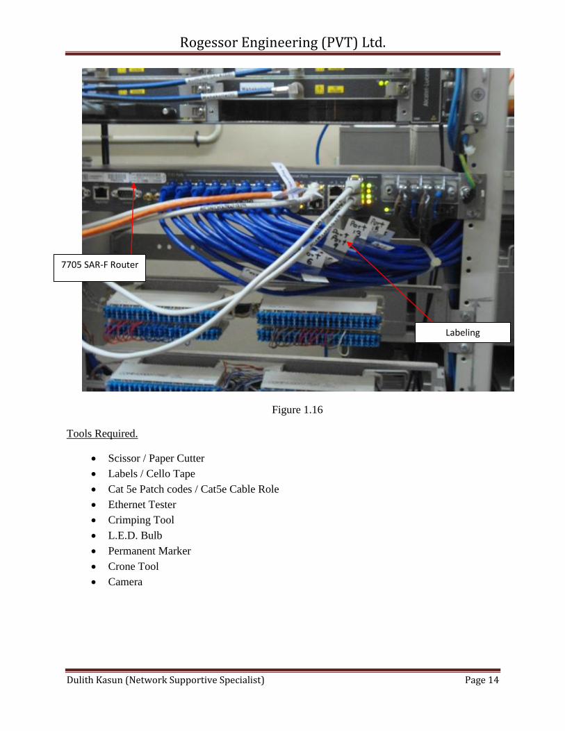
Figure 1.16
Tools Required.
Scissor / Paper Cutter
Labels / Cello Tape
Cat 5e Patch codes / Cat5e Cable Role
Ethernet Tester
Crimping Tool
L.E.D. Bulb
Permanent Marker
Crone Tool
Camera
Labeling
7705 SAR-F Router
Rogessor Engineering (PVT) Ltd.
Dulith Kasun (Network Supportive Specialist) Page 15
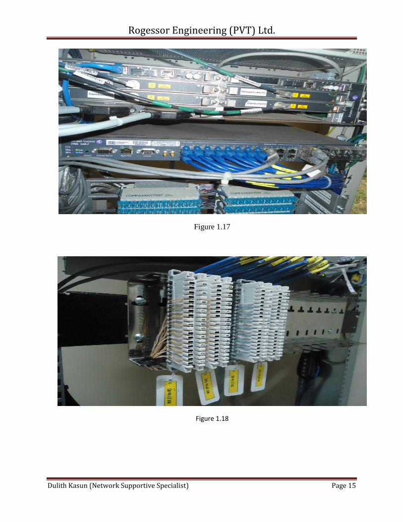
Figure 1.17
Figure 1.18
Rogessor Engineering (PVT) Ltd.
Dulith Kasun (Network Supportive Specialist) Page 16
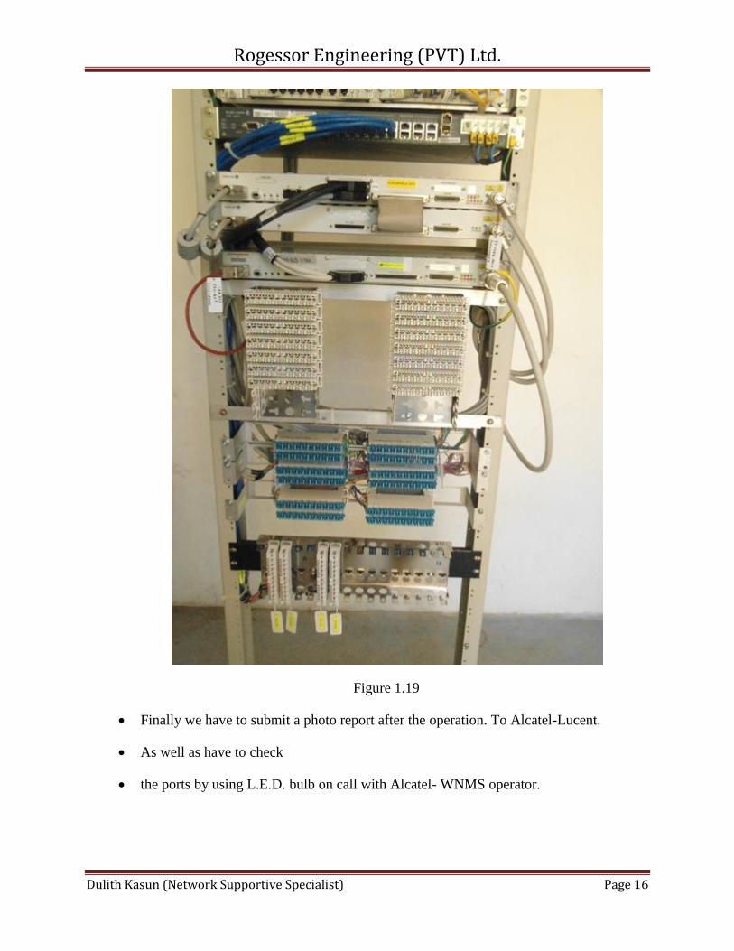
Figure 1.19
Finally we have to submit a photo report after the operation. To Alcatel-Lucent.
As well as have to check
the ports by using L.E.D. bulb on call with Alcatel- WNMS operator.


![Vian, Boris - La Hierba Roja [10354] (r1.3)](https://img.pdfslide.net/doc/110x75/56d6bd9e1a28ab30168eaebe/vian-boris-la-hierba-roja-10354-r13.jpg)