Embed Size (px)
Citation preview
- ---- --
BRL 1086 c . 1.A
k f l llllnllllu - - - ..IIIlIli. 11111111111111'"'~~Y Uhr "111111"
lit1 nnl~~~nn nnnn~~,. IIIIIIII~IIII IIIIIIIIII,. IIII~IIIIII 111111111111 llllllllllll~ ll11111111ll11 #IIIIIlIII1~ IIHIIRIIII
I ttl AllllllllU IIHIIIIIII~' llllllllllllll lllllllllll' IlllIl#IIlI ' [;.$I 11 11 11 11 11 11 II I1 !I 1 ' 11 11 11 11 11 11 11 II IIIII~" 11 11 11 I1 11 11
D 11 11 11 11 11 11 !!I! t! " ll llllllll llllll 11 ul!"" 11 11 11 11 11 11
I I:'FI ll11111111ll IIIIIIII~, llllllllllllll IIIIIIIII HHlllllll 1111 1111 IIIIIIIIIIH h IIIIIIIIHIIII IIIIHIIIIII IIIIIIIIIIII 111111 IIIHlllllllt Illl#IIIIIIIl 111111111111 llllllllllil 11
El!] . i IIIIIIh~~II~'" lRY RIIRll llllllllllllrl~ .Illlllll.,.,lrllllll
1 @
1111111111" ll I1 H H H ll ll ll k 'I H U II I1 '. d H H H Y ll ll l U ll ll il ll I1 ll iw gr;l .' ,
511 IANlIARY 1960 -. -. .-- [;$I 1'1 [,if1
[';I .. .. 181 k:C] ,
kf:j 1:Lj W . ,
fg] Ffi;]
[;g;l If1 . C
. ,: . ... I$] i'ra nnnadmnnt W G ~ U I L I I I ~ I ~ r VI nf t h o I I n r Arm11 IIIJ Prniod I I V J W V S hh IVU. , 5Rn?-O?-fK)l W W H
r r . - A _ - - - - . A , - - - ~ - ~ - + C + r n n e + m l ~ f i P A ~ P ~nIn. 11.814
[fj urananct: lv\arlayt:~~rc;~ 11 air ULIUI G LUUG /u*u
2 ; . ,. BALLISTIC RESEARCH LABORATORIES
snnmrr rnn n r r r n h n l h l ~ ~ ~ n ~ ~ C ) n\J(/ \IdDIARIC pQAn)FhrrC I A b U 3 r V K vrIrnrv\IlunI I U I ~ ur I Luvr n u ~ I \ ~ W I L I I I J
o r u I \In rI ID\rrn c u n p K WA\/FC DLII I I Y V b U l \ V ~ v J I I ~ W I \ r r n v LJ
LI-&L,-- f ' n m m h n w IYdll ldl l Ut:l Utfl
Joan M. Bartos
ABERDEEN PROVING GROUND, MARYLAND
B A L L I S T I C R E S E A R C H L A B O R A T O R I E S
REPORT NO, 1086
JANUARY 1960
TABLES FOR DETERMINClTION @ FLOW VARIABU GRADIENTS BEHIND CURVED SHOCK WAVES
Nathan Gerber
Joan M e Bartos
Department of t he Army Project No. 5BO3-03-001 Oriimnce Management Structure code - 5010.1l.814
(Ordnance Research and Development Project No. TB~-0108)
A B E R D E E N P R O V I N G G R O U N D , M A R Y L A N D
B A L L I S T I C R E S E A R C H L A B O R A T O R I E S
REPORT NO. 1086
~~erber/JMBartos/ebh Aberdeen Proving Ground, Md. January 1960
TABUS FOR DEZERMDUTION aF FLOW VARIABU G R A D m S BEHIND CURVED SHOCK WAVES
ABSTRACT
The shock wave r e l a t . i ~ n s r equations of is0energet. i~
two-dimensional or axisymmetric flows can be combined to yield
expressions for various useful quantities behind a shock wave if
the curvature is known in addition to the position and slope. Tables
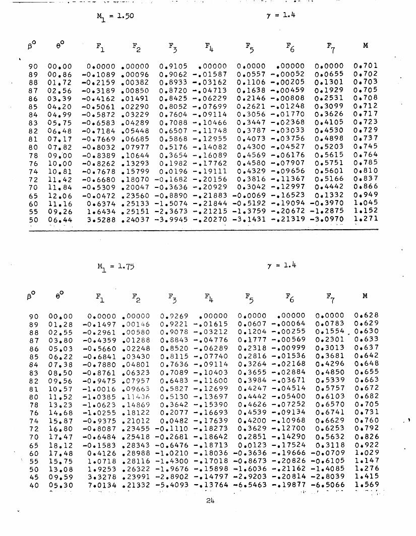
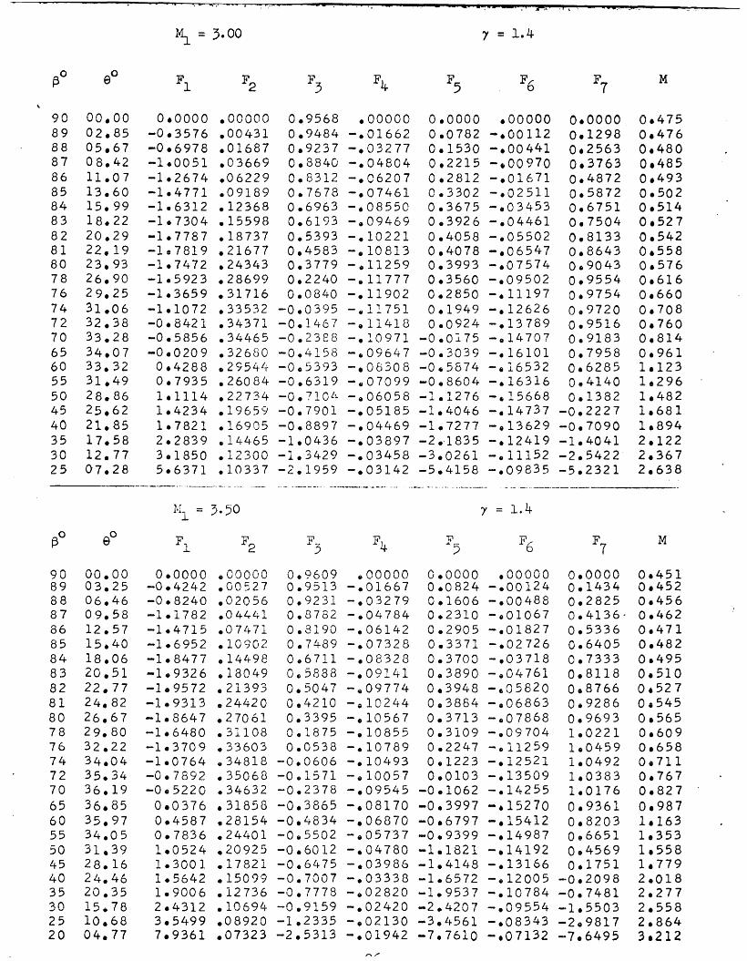
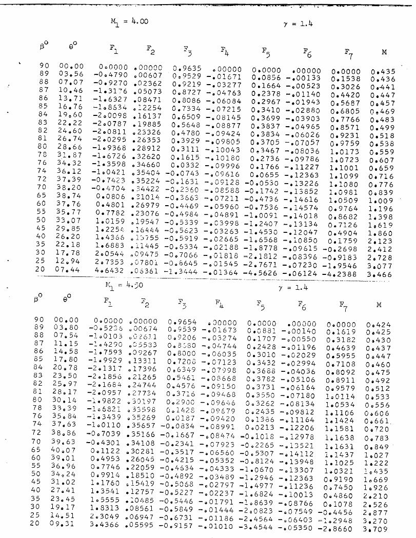
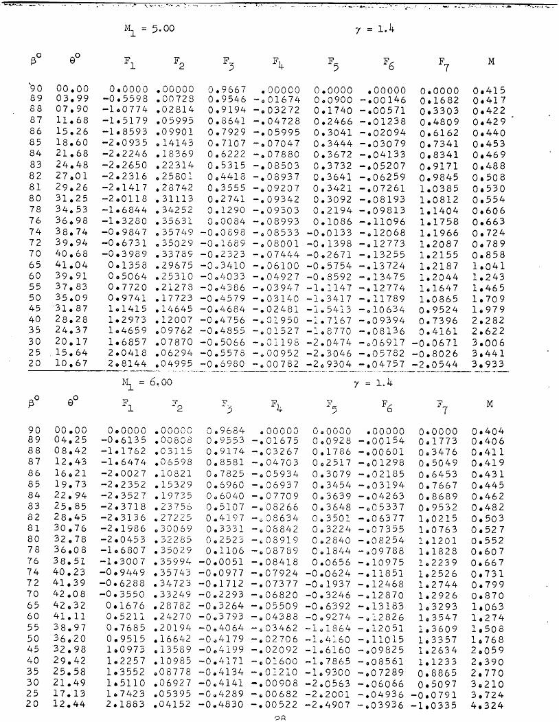
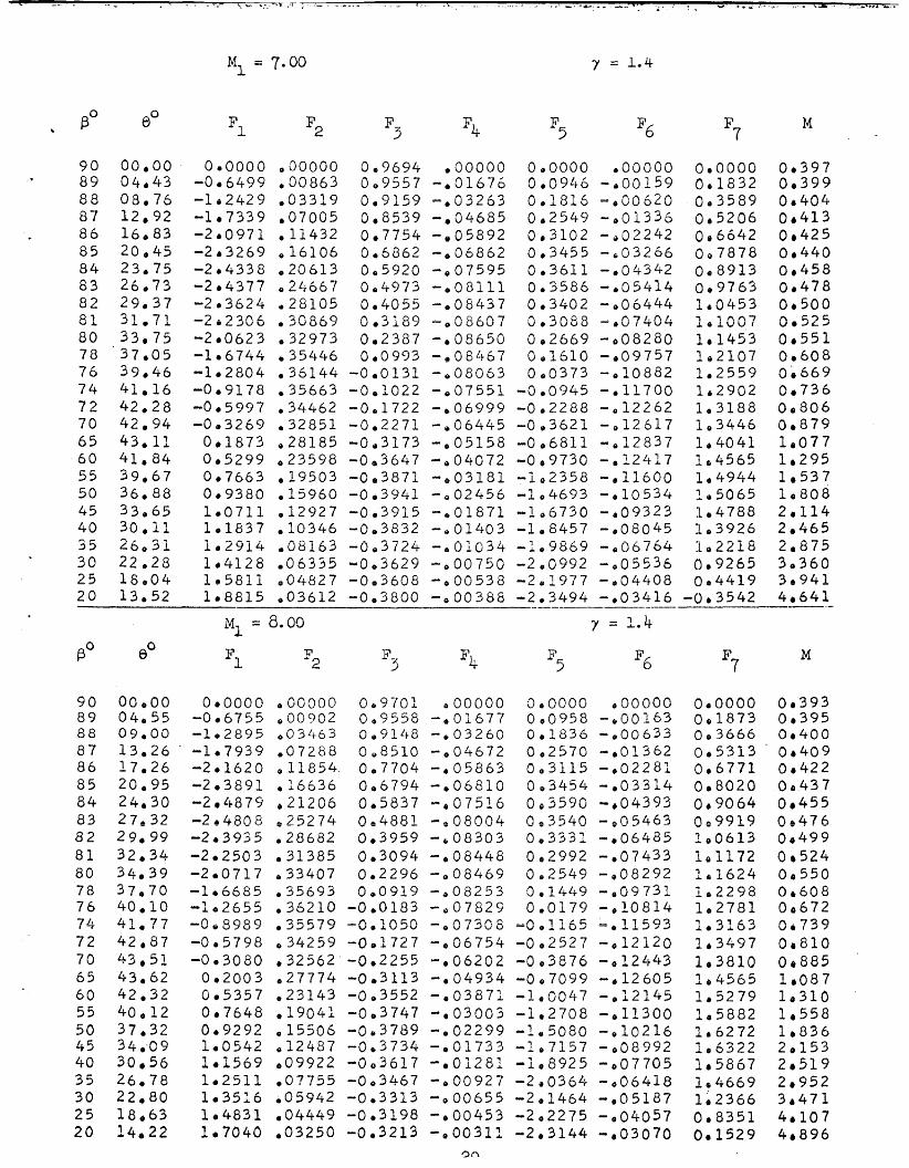
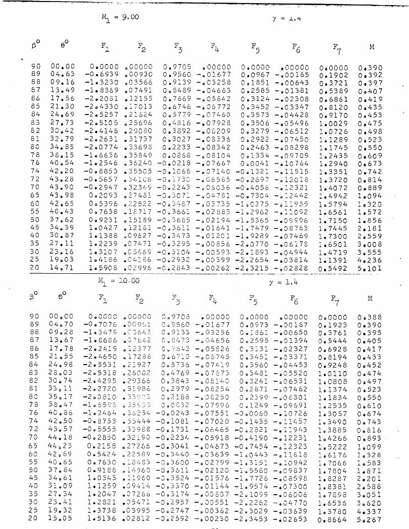
are presented here of computations, for y = 1,4, of seven functions of Mach number and shock wave slope, from which the following are
easily computed: 1) streamline curvature, 2) velocity gradient along
streamline, 3) angle between streamline and density contour, and 4) angle between stredine and Mach number contour. In addition, the
Mach number and angle of inclination of streamline are listed. A
Mach number range from 1.1 to 10 is covered by these computations.
A derivation of the shock gradient functions is presented; and
several applications of the calculations are given, including a set
of tables for determining the slope of the sonic line.
- rectangular coordinates - natural coordinates normal and tangential respectively
to stre-ine
2 2 2 1/2 = (cos B + g sin p)
- speed of sound = (ap/&) LIZ
- shock gradient functions
- enthalpy - curvature of shock wave - curvature of streamline - inverse of pressure ratio across shock = P1/P
- Mach number = M1 sin f3
- pressure - velocity - ratio of stagnation densities across shock - entropy - temperature - angle between shock wave and x-axis - ratio of specific heats (= 1.4 for air)
- 0 for 2-dimensiona,l flow 1 for axisymmetric flow
- angle between stredine and l i ne ~f c ~ n s t c q t density
- angle between stredine and x-axis - angle between streamline and line of constant
*I - -I_ ------- 7. men numDer
- density - arc length along shock wave
I. INTRODUCTION
The problem of determiaing the gradients of the flow variables
behind 8 shock wave in ieoenergetic two-dheneional flow hae been considered by several investigators 1 2 3 . ~hese grsdiente are very
useful; for instance, the slope of the streemline at shock polar
points i n the magraph pl-me c a be obbined from them (the Bueemann 4
"hedgehog" ) . A particularly simple derivation wae indicated by Sternberg , wing natural coordinates. It is found that the flow vsriable gradients
are proportiond. to the ehock wave curvature. Tablee of coefficients for 2
etreemline c m t u r e have been computed by Thomas for a limited range of Mach number,
The same gradients can be comguted for axiaynnnetric f l o w . However, theyare now linear combinations of the two shock curvatures, Kg in the
meridiaPal plane and l/r in the azimuthal plane. h he two-dimensional in obtained saqly by the lIr term.) Beesues of Ws
the general usefulness of these gradient functions is restricted in that
one can no longer, as in two-dimensional flow, obtain certain quantities
(e.g., elope of sonic l ine) without having t o specify the vsluee of r and
Kg, Expressions for the slope of these contours (density, pressure, WBch 5 number) have been given by Wood and Gooderum .
FIGURE 1.1
hide from the results of Thomas cited above no calculations
of +&e & ~ ~ e - ~ n t i ~ ~ d Q u e n t q i m k i t i e e haw to the &ors1 howledge
been published. This report supplies such a set of calculations ("shock
gradient iunctions" ) which can be used to determine significant flow in-
formstion f m m physical .measurements. It is felt that these computations
can also be helpful in obtaining a clearer general picture of flow behind
a curved shock wave. These fU~tion.8 will find further application in the
study of f l o w of a reLaxing ges behind shock waves at large Mach numbers.
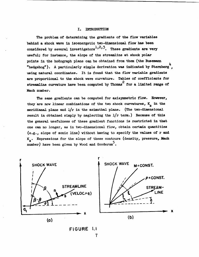
The particular quantities to be obtained here are (using the notation
of Fig. 1.1) : 1) bq/as, the velocity gradient along the streamline j 2) \A /\ - t rL, ,l,,, ,,,-I, ~ l o s (I 91, the cimvatiire of the etreamline; J) Q + 5, bu: asupc: -LC
of the isopycnal, or density contour; and 4) Q + k, the slope angle of the Mach number contour. It is assumed that the gas is ideal, and that the P7n-r J - n --4 - ~ r r - r - d 4 4 n a l ~ . . ~ r r a + ~ a a r n l . t m a a A A U W AD u - A auu r D c u u A u y r G arvq D W A G ~ A ~ L G O ~
The above flow quantities are obtainable from expressions having the
following simplified forms:
n f a . a\ v a\ f~ 1-1 9 M13 PI 4\13 53 P I
tan 5 - - + cF6(7, Ml, (lIrf
4
~ ~ ( 7 , M1, B) Ks + E ~ ~ ( 7 , M1, B) (l/r) tan L - - n i (7, M ~ , 8) K~ + E ~ ~ ( 7 , xl, (l/rJ 7
where e is equal to zero for t w o - m i o n a l flow and one for axisymmetric P 1 rrT-. LAUW. q & s, m e +he nqmer velocity, respectively, in t h e
free stream; tan f3 is the slope of the shock wave; 7 is the ratio of specific
heats. The angle Q = Q (M~, j3) is known from the shock wave relations e . g = , ~ e f . 6 ) :
The gradient f'unctions Fly F2, ...., F are derived in detail in 7
SectionIf. These functions for the most part are long and complicated
expressions in M and which do not lend themselves to analytical treat- 1
ment or easy hand computation. It is, however, feasible to calculate them m on a high speed computing machine. Thus the functions F 1" F2, . o . . , E ~ ,
8 , and M have been programmed for computation by the EWAC in the Ballistic
Research Laboratories, and they can be obtained quickly for any particular
case of supersonic flowby specifying H 1 and 7 i n t i e computing machine input.
The simple form of the expressions in Eqs. (1.1) suggests the practi-
cability of a compilation of the coefficients of Ks and l/r which could be
employed as a labor saving means of determining the desired quantities.
To this end, the present paper provides a series of tables of shock wave
gradient functions versus f3 for 7 = 1.4, with M1 as parameter.
The angle f is of special interest to the authors, particularly in calculating a flow field (velocity, streamlines, etc . ) from given inter- ferometric density data (see Ref. 5, 7, and 8). The information resulting
from the measured and Ks reduces the uncertainty in density near a shock
wave which is inherent in the interferometric method.
Sample hand computations have verified that the formulas used in this
report yield the as form-fias given in the referenceso
11. DERIVATION @ GRADIENT FUNCTIONS
m L - I--- m e present derivation follows the one indicated i n Ref. 4. In
natural coordinates the equations of isoenergetic flow of an ideal non-
viscous gas are
(b)
(c)
where e = 0 for two-dimensionrcl, = 1 for axisymmetric flow. The coordinates s r; leFg+,hs d o n g the stredine dlF4 the =r-t-hcg-nd ?-ra:ect=
ory of the streanline, respectively; q is the speed of flow, and Q is the
angle between the streamline and the free stream direction (x axis); p is the
density, and p the pressure, T is the temperature; M is the Mach number
( = o/a, where a = (bp/&)112 = speed of sound).
The two essential equations to be used here are
(a)
(b)
obtained from Eqs . (2.1) and the definition of the velocity of sound. he foregoing equations are given in Ref. 9 and 10.) Entropy remains constant
along streamlines,
If a is arc length along the shock wave: it is seen from the relation
that at the shock wave (2.3)
a a ag a a a = ( 1 = K s = cos (B - Q) + sin (p - 0)
where and K m e the slope and clmv%me, respectively, of t h e s
shock wave @ig. 1.1). As the coordinates are defined, curvatures are
positive where curves are concave upward and negative where concave
By means of Eq. (2.3), Eqs. (2.2) are replaced by two simultaneous
linear algebraic equations for and &/as. The coefficients of these
equations are now converted into the desired form; namely, that of Eqso
(1.1). For this purpose use is made of the following definitions and
relations which can be found in many textbooks and reference books (the
authors employed Ref. 6 mainly) :
The subscript 1 always refers to free stream conditions.
9 = A GI1'
3 3 => 1 /2 where A = (cos- B + g- sin- B)-'
After differentiation for aq/&, a@/?@, and as/@ (noting that &/as = o), one obtains expression for F1, F2,FJ, and Fq given by the
following sequence of formulas I
( l / q , ) -L - a d a s = F, K- + E F,, (l/r) 3 s 4
The following re la t ions , obtained from the flow equations, a re used
to find ( and 5 :
where the subscript t denotes the stagnation value (apt/& = apt /& = 0) ,
J . / ( ~ - ij - ij In = p / n = ~ = i - - g rtl t' rtl (see R e f . 6)
By means of Eqs . (2.3) and (2.25), ap/as and &/an can be expressed
in terms of ap/bs, ap/an, and other quantities already determined in this
report. Substituting these expressions into Eqs . (2.1), one then derives
expressions for ap/as a d &/an; a d putting these into the relation for
the angle between the density contour and the streamline, namely,
tan f = - (ap/hs)/(hp/an) (2.26)
one obtains F K + E F~ (111)
3 tan ' = I? Ks + E F6 (1/r) where
5
- 4 cos p F5 - r + l
A positive value of f indicates a counterclockwise mtation from the
streamline to the density contour.
The angle 5 between the Mach number contour and the streamline is determined fmm
tan s = - (aM/as)/(aM/an) = - (d/as)/(d/an), where k has the same sign convention as 5 . since
Id2 = (~d)/(*), &?as and &?/an can be expressed in terms of the derivatives of p and q,
which in turn are expressiblein terms of previously determined quantities.
Conseqyently one obtains
F K~ + E F~ (l/rj tan 5 = , where
F? K + E F6 ( l I r ) f s
2 I ( A 3 7 1 m 2 / n ) + 2 A g h p 1 - 2
s i n p 1 J
111. DISCUSSION (X? C-TIONS
Tabulations of the functions Fly F2, . . . . , F 7' 0, sad My calculeted
f o r y = 1.4, are presented in Section 4 fo r values of M1 - rang* from 1.1
+,c lQ.Qe 'Fhp ~ m c t l n m are l i s t e d in order of decreashg f3, from f3 = 90'
t o a value somewhat greater than p = ~ i n - ~ ( l / ~ ~ ) . The l i s t e d values of Y andp were chosen so as t o permit the determination of the functions t o a
reesonsble degree of accuracy f o r any M1 and p by means of graphical inter-
polat ion.
Figure 2.1 shows an example of resul t s obtainable from these calculations. & L,,J - * +hfi Trarqcl+qr\n u L A I~ZULU L~~~ r u v w r rur .,,,,,,, in slope of the constant density l ines
along the shock wave of a supersonic sphere i n nitrogen (shorn a t the l e f t )
determined from shock wave coordinate measurements a,nd the appropriate shock
gradient functions. For reference purposes, the left hand f igure shows the
sonic point and "Crocco point" (defined below), and indicates the location
of typical values of rKa. It must be noted tha t the accuracy of resui t s - like those in Figure 3.1 is res t r ic ted by the l u t e d accuracy of and Ka &a
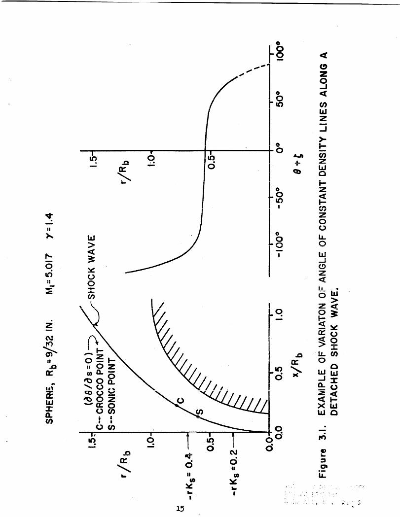
determined from experiment. (see Ref. 5 and 8 for discussion on deter- mination of B and KB .)
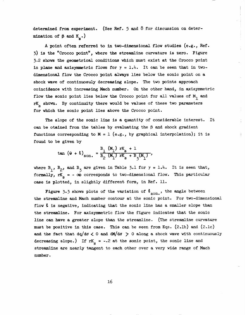
A point often referred to in two-dimensional flow studies (e.g., Ref.
3) is the "~rocco point", where the streamline curvature is zero. Figure
3.2 shows the geometrical conditions which must exist at the Crocco point in plane and axisymmetric flow for y = 1.4. It can be seen that in two-
dFmensional flow the Crocco point dways lies below the sonic point on a
shock wave of continuosuly decreasing slope. The two points approach
coincidence with increasing Mclch nurriber. On the other hand, in axisymmetric
flow the sonic point lies below the Crocco point for all values of M1 and
rKs shown. By continuity there would be values of these two parameters
for which the sonic point lies above the Crocco point.
The slope of the sonic line is a quantity of considerable interest. It
can be otained from the tables by evaluating the f3 and shock gradient
functions corresponding to M = 1 (e.g., by graphical interpolation); it is
found to be given by
where B 1, B2, and B are given in Table 3.1 for 7 = 1.4. It is seen that, 3
formally, rKs = - w corresponds to two-dimensional flow. This particular
case is plotted, in slightly different form, in Ref. 11.
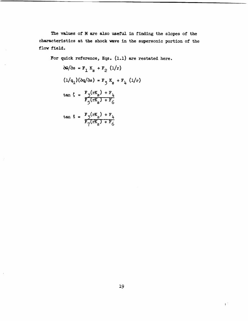
Figure 3.3 shows plots of the variation of the angle between
the streamline and Mach number contour at the sonic point. For two-dimensional
flow 5 is negative, indicating that the sonic line has a smaller slope than the streamline. For axisymmetric flow the figure indicates that the sonic
line can have a greater slope than the streamline. st he streamline curvature must be positive in this case. This can be seen from Eqs. (2.lb) and (2.1~)
and the fact that dq/do ( 0 and dM/du ) 0 along a shock wave with continuously
decreasing slope.) If rKs = -.2 at the sonic point, the sonic line and
streamline are nearly tangent to each other over a very wide range of Mach
number.

---..... Sonic point
Figure 3.2. Conditions for zero c u r v o t ~ r e of streamlrfie
id8 idss0 j a t shock wave i c r o c c o ~ o i n t j .

(NOTE: FOR THE r K c O CURVE, 8 +(= 8 )
80 1 I 1 1 1
I: I I J- - - - t - - -q- - - - I I i I - - - i R 0 -e
- 0 0 f I'
! A I \\\ I I I I i I i I I I - 1 -
--a . I I I I
rK,= O w v I ,. S- = -."& - na
r K s s - . 0 5
I.' I I
,T 1 1 rKes-.2 .I
I tK,=-.5
I 1 I r-I r K , z = a
-2Ci-i I I i / ' v= I/ n I I I I I 1 I
,*I - 1 I I I I
1
I S POSITIVE F O R A COUNTERCLOCKWISE I I I I / O ~ T A T I ~ \ M F P ~ U TuF 9 T R C A M I INE 10 THE I I I I / n~ 1 lvl- r \ v r ~ w rn I. w . - .--.-- -.---
- 6 0 1 ~ 71/,~wC LINE. E
II 1 Y ! I 1 I !
I I I II I A
I -80 r CORRESPONDS TO TWO:
I I / I ( m w u s , o N * L FLOW. 1 I I' / I I I
i i I I I -100 5 I 5
1
I 2 3 4 5 6 7
"": -.A,. A - r r r A ~ h p t \ A , C C l 1 e T m C I M C
FIGURE 3.3. V A R i A l IVN ur R N ~ L E oc I n c c l ~ 9 1 n r r r ~ w ~ c ~ u . ~
AND SONIC LINE AT SHOCK WAVE.
18
me vsl..aa -9 li errs a l - A ..lrrrA.l 4 - P-l-A-t-rr +LA C . ~ A I I I A* &LA A U G V C Y - 0 UL A.1 CLIC OIPV WCIW AU A ALLCLLU& bALC OIUYeD U I
characteristics at the shock wave in the supersonic portion of the
flow field.
For quick reference, Eqs. (1.1) are resteted here.
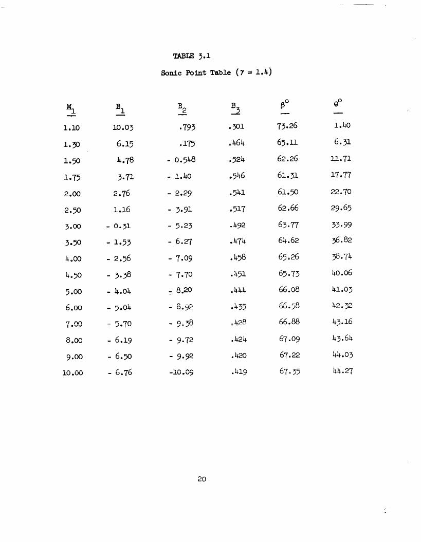
TABU 3.1
Sonic Point Table ( 7 = 1.4)
The authors wish to express their appreciation to Dr. Rapnd Sedney
for his helpful advice and to Mr. P a h e r Schlegel for programming and
performing the WAC calculations.
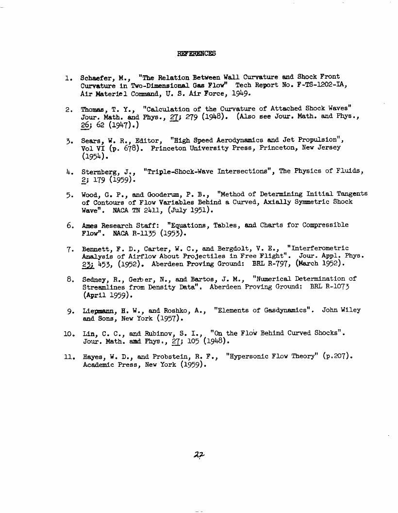
1. Schaefer, M., "The Relation Between W a l l Curvature and Shock Front Curvature i n Tvo-Dimensional Gas FW' Tech Report No. F-TS-1202-u, A i r Materiel Comnnand, U. 9. A i r Force, 1949.
2. Thomas, T. Y., "Calculation of the Curvature of Attached Shock waves" Jour . Math. and Phys . , 3~ 279 (1948). (Also see Jour . Math. and Phys . , 26; 62 (1947) .) -
3. Sears, W. R e , Editor, " ~ i g h Speed Aerodynamics and J e t FYopulsionii , Vol V I 678). Princeton University Press, Princeton, New Jersey (1954)
5. Wood, G. P., and Goodem, P. B., " ~ e t h o d of Determining I n i t i a l Tangents of Contours of Flow Variables Behind a Curved, Axially Symmetric Shock waveii. NACA TN 2411, ( ~ u l ~ 1951).
6. Ames Resesrch Staff : "~quat ions, Tables, and Charts for Compressible F W NACA R-1135 (1953).
7. Bennett, F. D., Carter, W. C ., aad Bergdolt, V. Em, "Interfernmetric Analyeis of Airflow About Projectiles i n Free ~ l i ~ h t " . Jour. Apple Phys. a 453, (1952). Aberdeen Proving Ground: BRL R-797, ( k c h 1952).
8. Sedney, R., Gerb er , N., and Bartos, J. Me, "~umerical Determination of S t r e m i n e s f l.om Density Data'' . Aberdeen Proving Ground: BRL R-1073 ( ~ p r i l 1959) l
9. Lie-, H. W., and Roshko, A., "Elements of ~asd~namics". John Wiley and Sons, New York (1957).
10. Lin, C. C., and Rubimv, S. I., "On the low Behind Curved shocks" . JW. w h . and P-w., 105 (1948).
11. Hayes, W e Dm, and Probstein, Re F . , " ~ ~ p e r s o n l c Flow ~heory" (P. 207). Academic Press, New York (1959).
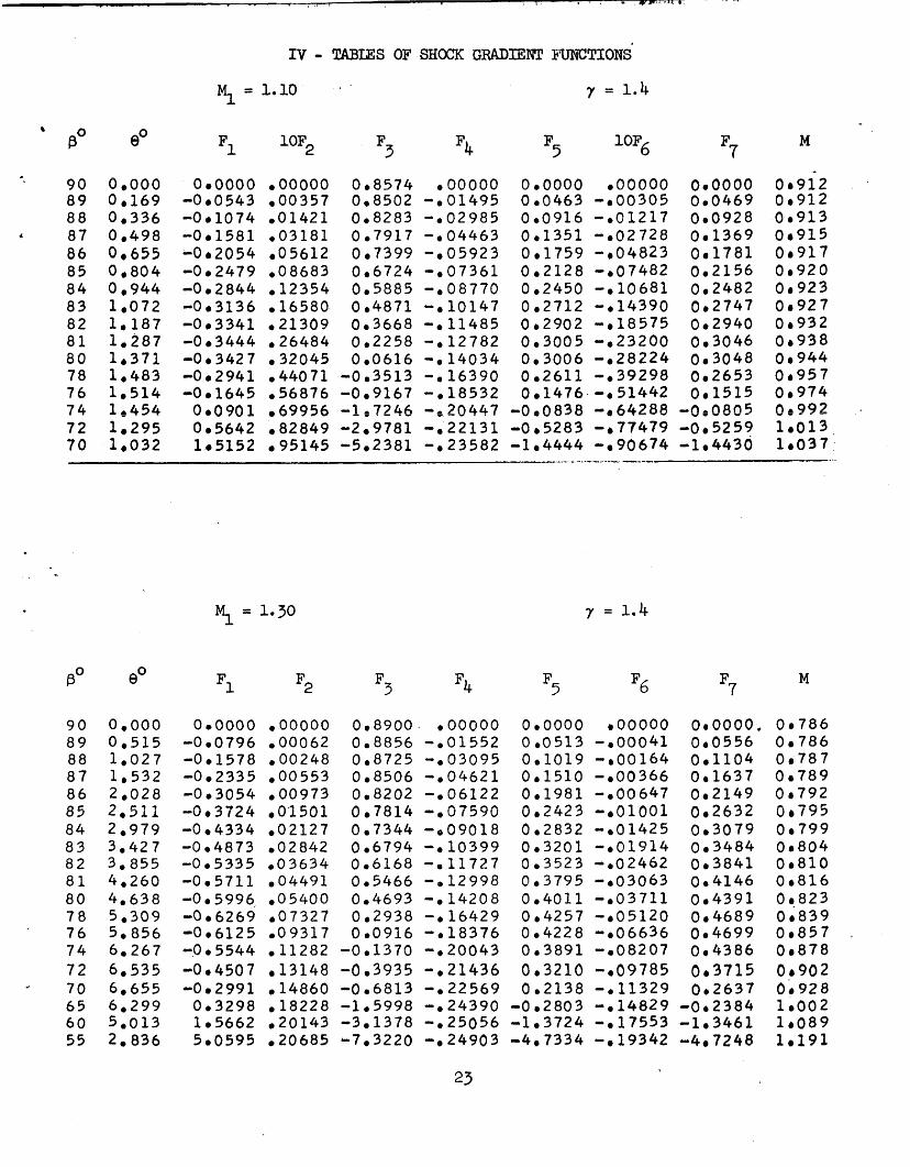
IV - TABUS OF SHOCK GRADIENT 3FIJNCTIONS
00.00 00 .86 01 .72 02 56 03 .39 04.20 0 4 . 99 05.75 06 .48 07.17 0 7 0 8 2 nn 'nn V 7 . V V
10.00 1 0 . 8 1 11 .42 11 .84 12 .06 11 .16 09 .26 06 .44 . .
' l i ' B Z' j+ ti' w ?3 '1 '2 ' 6 ' 7

n n n n n ~ U U U U U 0 0 9 6 8 4 n n n n h ouvuuu Oo0030 0 0 0 0 0 0 (jogc(jfi O08G6 009553 -001675 000928 -eOO154 0 ~ 1 7 7 3
Ti' v. "4 3'
5 '6 F P- F 1 ' 2 5 7
nnnnn 0 U V \ J \ I U
3 0 9 5 : .?364-3 0 6 7642 .I2377 17288
0 2 1 9 2 7 7 r A ? ?
0 L O L J L J L .
2 9 3 6 6 .?I986
Y 3 ' ; " C . A
355,;tj
.3,3254 3 5 4 9 4 - r ~ n n
0 3 3 Y b O
3 2 3 1 3 3 7 3 c r ,
b L 1 i u w
,22589 , 2.2483 ,14360 .ll960
A T - r o b I L O O
? & I 7 i . U - / - r l A.
,03995 .02812
nnnnn n nnnn e w u v u Y L J P U U V U
- 0 0 0 1 6 7 0 0 1 9 2 3 - . 0 0 6 5 0 003761 - 0 0 1 3 9 4 0 0 5 4 4 4 - 6 0 2 3 2 7 0 6 6 9 2 8 -003371 O a 8 1 9 4 - 0 0 4 4 5 3 0,9248 - a 0 5 5 2 0 1.0110 -0c6521 1 0 c 8 e 8 - , 0 7 4 5 2 l e 1 3 7 4 - 3 O E 3 0 1 1 . 1 8 3 4 - 0 9 9 5 9 1 1.2535 - 0 1 0 7 2 6 1 0 3 0 5 7 -011457 1,3fi-90
n , , f i r - 0 1 1 y - 3 1 0 3 u u 3
m e 1 2 2 3 1 l o 4 2 6 6 - , I 2 3 2 3 1,5222 - = l l 8 I f i 1.6176 - 0 10942 1 0 7 0 6 5 - a 0 9 8 3 7 1 0 7 8 0 4 - 0 0 8 5 9 8 1 0 8 2 8 7 - - - , 0 7 3 0 0 l , a 3 u l
n r n n ~ - ~ U O U U O 1 0 7 6 9 3 = , 3 4 7 7 0 I O U J - I U 1 L C ~ L
- 0 0 3 6 3 9 1 0 3 7 8 0 - r 0 2 6 5 3 0 , 8 6 6 4
NO. of Copies
NO. of Organization Copies -
Director 1 Iu'ational, Aeronautics and Space Administration
T m n m l nv Raaasnnh IIA-+A- r r = o c - bu uCUbCL
W 1 e y Fierl , W r g i a g Attn: . G. P, W o o d - 1
Director National Aeronautics and Space Administration
1cnn w H L - - - - L -T T T
1 I;)CU n DxreeT;, n. w. Washington 25, D. C. Attnr Diviainn of Rese-ch
Informat ion I
Army Research Off ice Arlington H a l l Station -- - Ariington, vrrginia 1 A &A-
a b b L 1 i Lt. Cole $0 e
Commending General Army Ballistic Missile Agency 1 Reds tone Arsenal, Alabama Attn: Technical Library
Commander A-tr Rnnlrcl+ A Il..-la~a r u v r b u b n x z u cluu ULLIUCU
Missile -Agency - I
Redstone &se~al, Alabama Attn: Technical Library
o m - O T L
com&iw (yenerd
A m t r nr.Anam,a ~ -1ao .11 - f i r r - n - ~ - u a + J W r - A b G A . A A . O O A I C UU-U
Redatone Arsenal I Alabama Attn: Major D. H. Steininger
Commanding General White Sands Missile Range 1 Nnw Mnv-Inn w A . 4 G A A c . V
Attnt flRTTR.q-Ts -TE
Zlos Alanaos Scientific Laboratory
P. 0. BOX 1663 Las m-s, New &Aoo
A h D, Tnn -- -- , I.-. 30 Memorial Drive Cambridge 42, Massachusetts
Applied Physics Laboratory &2i Georgia Avenue Silver Spring, Maryland
AVCO Research aborgtcry Wilmington, Massachusetts Attn: Dr. Mac C. Adams
Boeing Airplane Company Seattle 14, Washington A&&-. abbLLi ]jr. 3. w e r ~
C O W ' Division of General Dyaamics Corporation
Ordnance Aerophysics Lab. Daingerfield, Texas
CO*AE. Division of General Dynmcr ! Corporation
Sasl Diego Division San Diego, Calif ornla ~ttn: R. D. Unneii
Cornell Aeronautical Lab., Inc. 4453 Gemgee Street Buffalo 5, New York Attn: Dr. F. .K. Moore
Cornell University G r & u t e School of
Aa-rrmrrr .+- t - 1 7 ----a -- G A A r u 4 & A 1 1 c c z 4 - I 4 5
IthA-c&, New Yerk Attn: Prof. W. R. Sears
DISTRlBVl!ION LIST
Chief of Ordnance Degart~nt of the Army Washington 25, D. C. Attn: - m- See
C o m d i n a Officer Dianond Ordnance Fuze Lab. Washington 25, D. C. Attn: O m L - 012 Office of Technicd
a . . ---3 -- DervlceE
n--ar*+mar?+ cf 'C~mmerce us- -LA-
Washington 25, D. C.
Dlrector Armed Services Technical Information Plgency
Arlington Hall Station A --1 r , ,A-, 7 V 4 Wmq m-1 ArLrLl& W L L , v r l B-A-
A t t n : T E R
British Joint Services Mission
1800 K Street, N. W e Washington 6, D. C. Attn: Reports OPficer
Cnn&sn Staff 2450 Massachusetts Avenue Washington 8, D. C.
Chief, Bureau of Naval Weapons &partme-' -0 LL- ?a '"' n UI ~ U C r1avy + , D i ;
Commander U. S. Naval Weapons Laboratory Dahlgren, Virginia
NO. of Copies Organization - - -
2 Commander \TI--- 1 fkr7.~1mm/.f i T . m h r \ . ~ ~ l . f . n y ~ L ' I a v w V l WroUbb -uv.lu---J
mite O&k Silver Spring, Maryland Attn: Library
Commander Naval &dnance Test Statioii China -e, Cd;forris
Attn: Technicd Library
Superintendent Naval Postgraduste School Monterey, California
Commander A 3 -- TT-3 " 4 +.r nu- UULVCL-DL UJ = A i r Force Base Alabama Attn: Air University Library
Commander Air Research a d b v e l ~ p ~ c t Command
A - d r r l r r . r a finre@ R u e r S I L u - G w D & V* -- -- - W~shtggton 25, D. C
1 Director National Aeronautics and Space Administration
k w i s Fl ight P r o ~ d ~ i ~ Z l T ~ K L U W A n h r \ w m + n r l r u UWL J
Cleveland Airport Cleveland, Ohio
1 Director National Aeronautics and Space Administration
A,,- D - n a m w n h p m n t . ~ ~ AJIlCD n vrrr.vu-
gcffett F i e l d , California
DISTRIBUTION LIST
No. of Copies
No. of Copies Organization Organization
California Institute of Technology
Gi-genheb A e r ~ p ~ u + , i ~ a l h h . 1500 Normandy Drive Pasadena 4, California Attn: Prof. L. Lees 1
Prof. H. W. Liepmann
Jet Propulsion Laboratory California Institute of
rn,,L--7 ..--- A c L L U L U Lu&y
Pasadena 3, California
Lockheed Aircraft Corporation Research and Development Laboratory
Missile Systems Division Palo &to, California Attn: Dr. D. Bershader
1 . Duke University Box CM, Duke Station Durhan, North Carolina Attn: Dr. R. J. Duffin
Glenn L. Martin Company Baltimore, Maryland Attn: S. C. Traugott
Douglas Aircraft Company 3000 Ocean Park Blvd. Santa Monica, California A++- e . &. II. buskin
Mr. R. J. Hakkinen Space Technology Laboratories, Inc .
P, 0. Box 95002 Los 45, California Firestone Tire and Rubber
company Defense Research Division 1 &on 17, Ohio
Ramo -Wooldridge Thoxpson 57760 Arbor Vitae Street Los Angeles '45, California
General E lec t r ic Company Aeronautics and Ordnance 1 Systems Division
1 River Road Schenectady 5, New York Attn: Dr. H. T. Nagamatsu
Dr. D. R. White
University of Maryland Institute for Ffluid Dynamics and Applied Mathematics
College Park, Maxyland Attn: Mr. S. I. Pai
University of Southern California Engineering Center
I;os Angeles 7, California
General Electric Company MSVD 3198 Chestnut Street Philadelphia, Pennsylvania Attnt Dr. F. G. Gravalos Princeton University
Aeronautical Department Forrestai Research Center Princeton, New Jersey Attn: Prof. W. Hayes
Prof. J. Bogdonoff
North American Aviation, Inc. 12214 Lakewood Blvd. Downey, California Attn: Aerophysics Laboratory
DISTRIBUTION LIST
No. of Copies 7
Organization No* of Copies
1 Brown University 1 Graduate Div. of Applied Mathematics
Providence 12, Rhode Island Attn: Dr. R. Probstein
Rensselaer Polytechnic Institute 2 Troy, New York Attn: Prof. T. Y, Li
Prof. G. H. Haadelman
W t e d Aircraft Corporation Research Department 1 East Hartford 8, Connecticut
University of Illinois Aeronautical Institute U r b a n a , Illinois
Standford University Palo Alto, California Attn: Dr. M. D. Van Dyke
Organization
Dr. L. H. Thanas Watson Scienttfic Computing Iaboratory
612 West 116th Street New York 27, New York
Professor G. F. Carrier H, W. Ehmons
Division of Applied Science Harvard University Cambridge 38, hkssachusetts
Professor F, H. Clauser, Jr. Johns Hopkins University Department of Aeronautics Baltimore 18, Wryland
Dr. A. E. Puckett Hughes Aircraft Company Florence Avenue at Teal St. Culver City, California


![11111111111111 Ill lllll lllll lllll ... · United States Patent[I91 11111111111111 Ill lllll lllll lllll lllllllllllllllllllllllll llllllllllllll Ill1 USOO5288393A [II] Patent Number:5,288,393](https://img.pdfslide.net/doc/110x75/60362574497c7e078e7780eb/11111111111111-ill-lllll-lllll-lllll-united-states-patenti91-11111111111111.jpg)