Embed Size (px)
Citation preview


MODEL NO. PAGE EVERVISION
VGG322424-6UFLWA SPEC & SAMPLE 2
1. Table of Contents
No. Contents Page
1 Table of Contents 2
2 Record of Revisions 3
3 Module Numbering System 4
4 Application 5
5 Features 5
6 General Specifications 5
7 Absolute Maximum Ratings 6
8 Electrical Characteristics 7
9 Block Diagram 9
10 Input / Output Terminals Pin Assignment 10
11 Interface Timing 12
12 Instruction Description 17
13 Optical Characteristics 18
14 Reliability Test 21
15 Packaging 22
16 Precautions 23
17 Outline Drawing 24
18 Definition of Labels 25
19 Incoming Inspection Standards 27
MODEL NO. PAGE EVERVISION
VGG322424-6UFLWA SPEC & SAMPLE 3
2. Record of Revisions
Rev. Comments Page Date 1 Preliminary Specification was first issued All 12/10’07

MODEL NO. PAGE EVERVISION
VGG322424-6UFLWA SPEC & SAMPLE 4
V G G 3224 24 – 6 U F L W A3. Module Numbering System
MODEL NO. PAGE EVERVISION
VGG322424-6UFLWA SPEC & SAMPLE 5
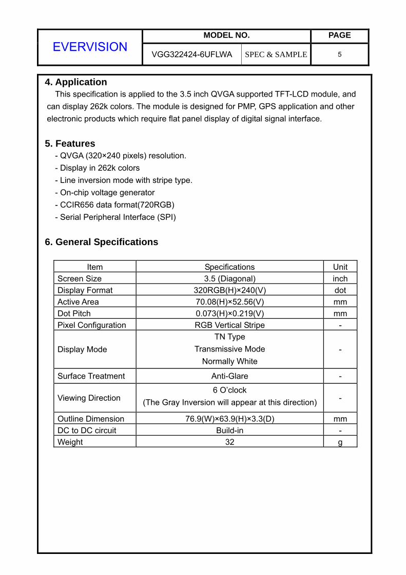
4. Application This specification is applied to the 3.5 inch QVGA supported TFT-LCD module, and can display 262k colors. The module is designed for PMP, GPS application and other
electronic products which require flat panel display of digital signal interface.
5. Features - QVGA (320×240 pixels) resolution. - Display in 262k colors - Line inversion mode with stripe type. - On-chip voltage generator - CCIR656 data format(720RGB) - Serial Peripheral Interface (SPI)
6. General Specifications
Item Specifications Unit Screen Size 3.5 (Diagonal) inch Display Format 320RGB(H)×240(V) dot Active Area 70.08(H)×52.56(V) mm Dot Pitch 0.073(H)×0.219(V) mm Pixel Configuration RGB Vertical Stripe -
Display Mode TN Type
Transmissive Mode Normally White
-
Surface Treatment Anti-Glare -
Viewing Direction 6 O’clock
(The Gray Inversion will appear at this direction) -
Outline Dimension 76.9(W)×63.9(H)×3.3(D) mm DC to DC circuit Build-in - Weight 32 g

MODEL NO. PAGE EVERVISION
VGG322424-6UFLWA SPEC & SAMPLE 6
7. Absolute Maximum Ratings 7.1 Absolute Ratings of Environment
Value Item Symbol
Min. Max. Unit Note
Storage Temperature TST -30 +80 °C (1) Operating Ambient Temperature TOP -20 +70 °C (1)
Note (1) Temperature and relative humidity range are shown in the figure below. (a) 90%RH Max. (Ta≦40°C). (b) Wet-bulb temperature should be 39°C Max. (Ta>40°C). (c) No condensation.
7.2 Electrical Absolute Ratings
7.2.1 TFT-LCD Module (Ta=25±2°C, GND=VSS=0V)
Value Item Symbol
Min. Max. Unit Note
Digital Power Supply Voltage VCC VSS-0.3 5.0 V - 7.2.2 Backlight Unit
(Ta=25±2°C) Value
Item SymbolMin. Max.
Unit Note
Forward current If - (30) mA (1) Reverse voltage VR - (30) V (1)
Note (1) Permanent damage to the device may occur if maximum values are
exceeded or reverse voltage is loaded.
MODEL NO. PAGE EVERVISION
VGG322424-6UFLWA SPEC & SAMPLE 7
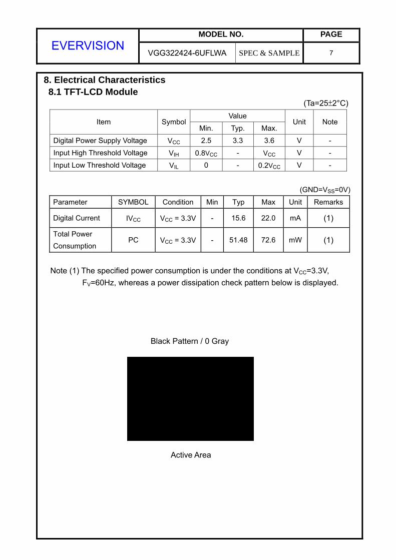
8. Electrical Characteristics 8.1 TFT-LCD Module
(Ta=25±2°C) Value
Item SymbolMin. Typ. Max.
Unit Note
Digital Power Supply Voltage VCC 2.5 3.3 3.6 V -
Input High Threshold Voltage VIH 0.8VCC - VCC V -
Input Low Threshold Voltage VIL 0 - 0.2VCC V -
(GND=VSS=0V)
Parameter SYMBOL Condition Min Typ Max Unit Remarks
Digital Current IVCC VCC = 3.3V - 15.6 22.0 mA (1)
Total Power Consumption
PC VCC = 3.3V - 51.48 72.6 mW (1)
Note (1) The specified power consumption is under the conditions at VCC=3.3V, FV=60Hz, whereas a power dissipation check pattern below is displayed.
Active Area
Black Pattern / 0 Gray

MODEL NO. PAGE EVERVISION
VGG322424-6UFLWA SPEC & SAMPLE 8
8.2 Backlight Unit (Ta=25±2°C)
Value Item Symbol
Min. Typ. Max. Unit Note
LED Voltage VL - (19.5) - V (1) LED Current IL - (20) - mA (1)
Power Consumption PBL - (390) - mW (1)
Note (1) The driving design of backlight unit is dependent on serial consideration of six LEDs.

MODEL NO. PAGE EVERVISION
VGG322424-6UFLWA SPEC & SAMPLE 9
9. Block Diagram TFT-LCD Module with Backlight Unit
TFT LCD PANEL320 x (RGB) x 240 Pixel
BACKLIGHT UNIT
LED_A
LED_K
Vss
VCC
DOTCLK
RESET
RR0~RR7
CSB
SDISCK
MODEL NO. PAGE EVERVISION
VGG322424-6UFLWA SPEC & SAMPLE 10
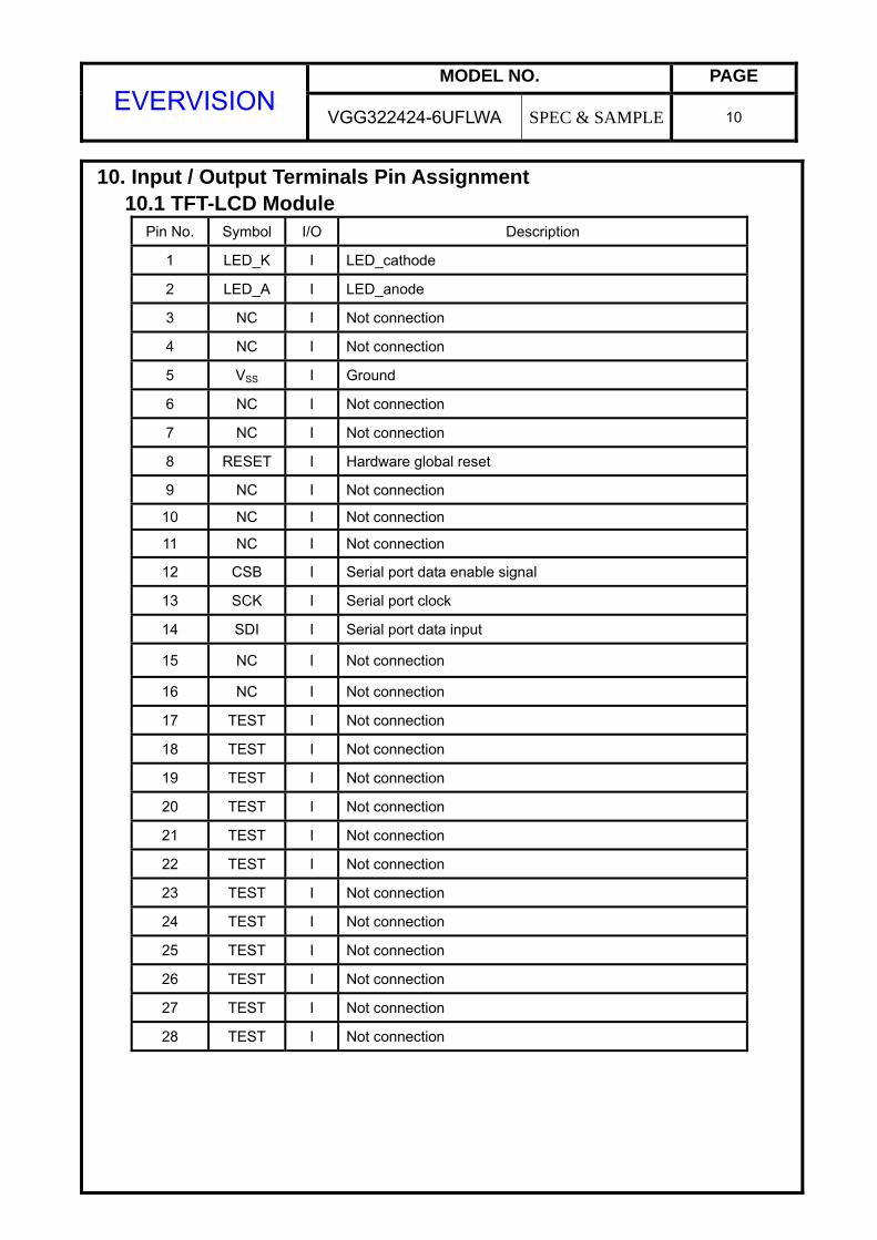
10. Input / Output Terminals Pin Assignment 10.1 TFT-LCD Module
Pin No. Symbol I/O Description
1 LED_K I LED_cathode
2 LED_A I LED_anode
3 NC I Not connection
4 NC I Not connection
5 VSS I Ground
6 NC I Not connection
7 NC I Not connection
8 RESET I Hardware global reset
9 NC I Not connection
10 NC I Not connection
11 NC I Not connection
12 CSB I Serial port data enable signal
13 SCK I Serial port clock
14 SDI I Serial port data input
15 NC I Not connection
16 NC I Not connection
17 TEST I Not connection
18 TEST I Not connection
19 TEST I Not connection
20 TEST I Not connection
21 TEST I Not connection
22 TEST I Not connection
23 TEST I Not connection
24 TEST I Not connection
25 TEST I Not connection
26 TEST I Not connection
27 TEST I Not connection
28 TEST I Not connection

MODEL NO. PAGE EVERVISION
VGG322424-6UFLWA SPEC & SAMPLE 11
Pin No. Symbol I/O Description
29 TEST I Not connection
30 TEST I Not connection
31 TEST I Not connection
32 TEST I Not connection
33 NC I Not connection
34 NC I Not connection
35 NC I Not connection
36 NC I Not connection
37 NC I Not connection
38 NC I Not connection
39 NC I Not connection
40 NC I Not connection
41 NC I Not connection
42 VSS I Ground
43 RR7 I
44 RR6 I
45 RR5 I
46 RR4 I
47 RR3 I
48 RR2 I
49 RR1 I
50 RR0 I
CCIR656 input data
51 DOTCLK I Clock signal
52 TEST I Not connection
53 TEST I Not connection
54 NC I Not connection
55 VCC I Digital power

MODEL NO. PAGE EVERVISION
VGG322424-6UFLWA SPEC & SAMPLE 12
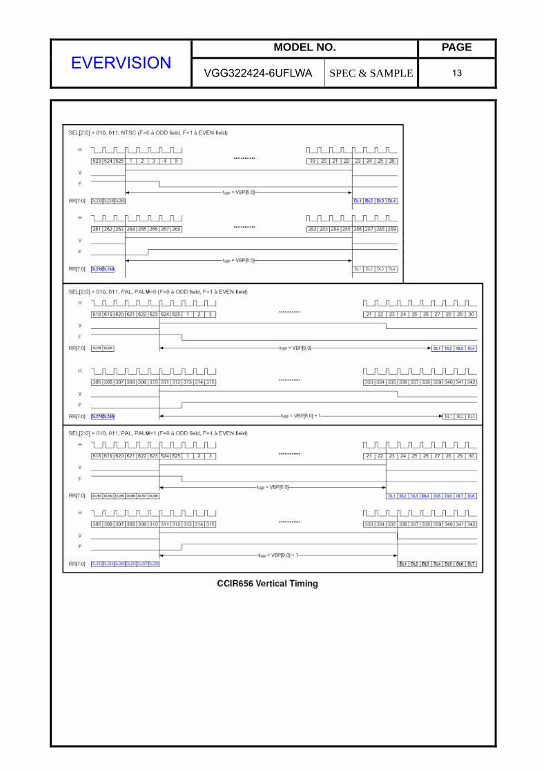
11. Interface Timing 11.1 Input Signal Characteristics
MODEL NO. PAGE EVERVISION
VGG322424-6UFLWA SPEC & SAMPLE 13

MODEL NO. PAGE EVERVISION
VGG322424-6UFLWA SPEC & SAMPLE 14
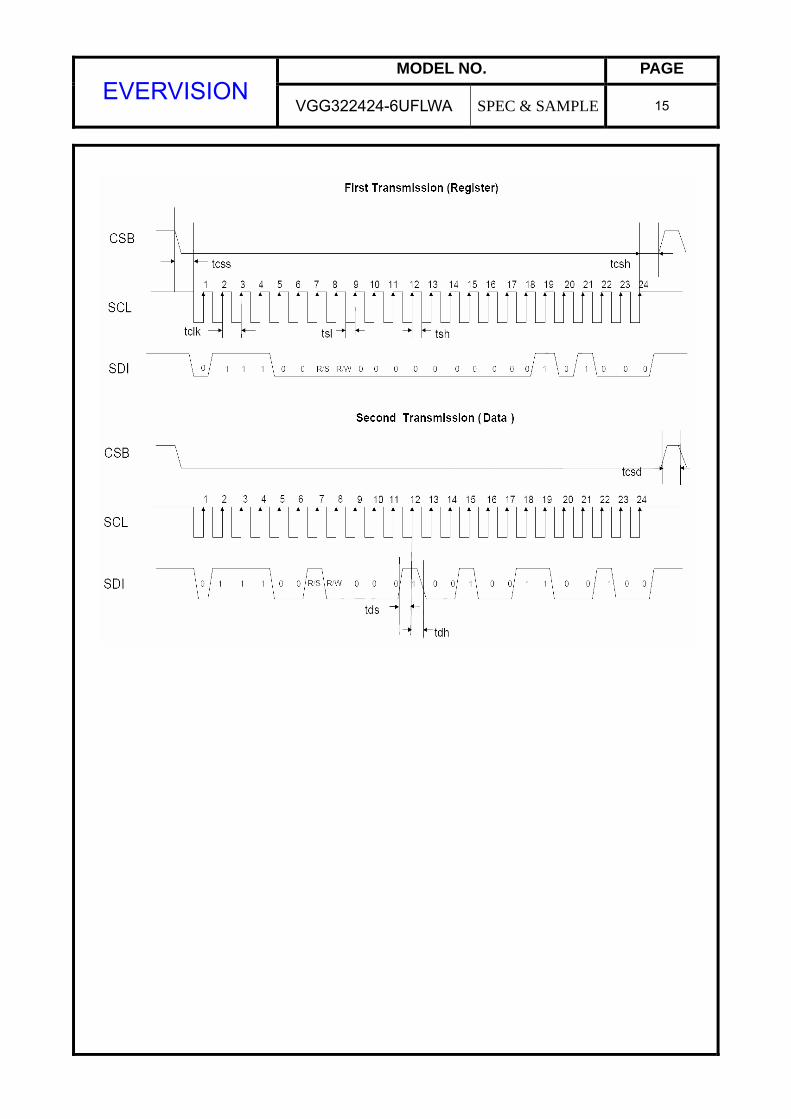
11.1.2 SPI Interface
R/S R/W status
0 0 Write SPI address
1 0 Write SPI data
MODEL NO. PAGE EVERVISION
VGG322424-6UFLWA SPEC & SAMPLE 15
MODEL NO. PAGE EVERVISION
VGG322424-6UFLWA SPEC & SAMPLE 16
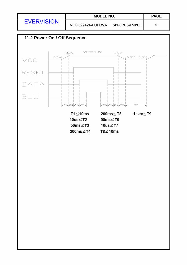
11.2 Power On / Off Sequence

MODEL NO. PAGE EVERVISION
VGG322424-6UFLWA SPEC & SAMPLE 17
12. Instruction Description SPI Command Table

MODEL NO. PAGE EVERVISION
VGG322424-6UFLWA SPEC & SAMPLE 18
13. Optical Characteristics The optical characteristics should be measured in a dark environment ( 1 lux)≦
or equivalent state with the methods shown in Note (4).
Item Symbol Conditions Min. Typ. Max. Unit Note
Contrast Ratio CR 150 350 - - (2)
Response Time TR+TF - 50 - ms (3)
Luminance(Center) Y 220 (270) - cd/m2 (4)
Brightness uniformity BUNI 80 - - % (5)
Rx 0.510 0.560 0.610 - Red
Ry 0.370 0.420 0.470 - Gx 0.210 0.260 0.310 -
Green Gy 0.620 0.670 0.720 - Bx 0.090 0.140 0.190 -
Blue By 0.030 0.080 0.130 - Wx 0.200 0.250 0.300 -
Color
Chromaticity
White Wy
θx=0°, θY =0°
Viewing Normal
Angle
0.300 0.350 0.400 - θx+ 55 70 -
Horizontal θx- 55 70 -
θY+ 40 60 - Viewing Angle
Vertical θY-
CR≥10
50 70 -
deg.
(1),(4)

MODEL NO. PAGE EVERVISION
VGG322424-6UFLWA SPEC & SAMPLE 19
Note (1) Definition of Viewing Angle (θx, θy): Note (2) Definition of Contrast Ratio (CR):
Note (3) Definition of Response Time (TR, TF):
12 o’clock direction
θy+ = 90º
6 o’clock
θy- = 90º
θx− θx+
θy- θy+
x- y+
y- x+
Normal
θx = θy = 0º
θX+ = 90º
θX- = 90º
100%
90%
10%
0%
Time TF
Optical
Response
TR

MODEL NO. PAGE EVERVISION
VGG322424-6UFLWA SPEC & SAMPLE 20
Note (4) Measurement Set-Up: The LCD module should be stabilized at a given temperature for 30 minutes
to avoid abrupt temperature change during measuring. In order to stabilize the luminance, the measurement should be executed after lighting Backlight for 30 minutes in a windless room.
Note (5) Definition of brightness uniformity Brightness uniformity=(Min Luminance of 9 points)/(Max Luminance of 9 points)×100%
Photometer (TOPCON BM-7 Fast)
Field of View = 1º
500 mm
LCD Module
LCD Panel
Center of the Screen
Light Shield Room
(Ambient Luminance < 1 lux)

MODEL NO. PAGE EVERVISION
VGG322424-6UFLWA SPEC & SAMPLE 21
14. Reliability Test
No. Test Items Test Condition Remark
1 High Temperature Storage Test Ta= 80 240 hours - 2 Low Temperature Storage Test Ta= -30 240 hours -
3 High Temperature Operation Test Ta= 70 240 hours -
4 Low Temperature Operation Test Ta= -20 240 hours -
5 High Temperature and High Humidity Operation Test Ta=60 90%RH 240 hours -
6 Electro Static Discharge Test (non-operating)
-Panel Surface/Top Case : 150pF, 330Ω Air: ±15kV, Contact: ±8kV
-
7 Mechanical Shock Test (non-operating)
Half sine wave, 80G, 11ms 3 times shock of each six surfaces
-
8 Vibration Test (non-operating)
Sine wave, 10 ~ 55 ~ 10Hz, 3 axis, 2 hours/axis -
9 Thermal Shock Test (non-operating) -20(30min) ~ 70(30min),100 cycles -
10 Drop Test(with Carton) Height: 80cm 1 corner, 3 edges, 6 surfaces -

MODEL NO. PAGE EVERVISION
VGG322424-6UFLWA SPEC & SAMPLE 22
15. Packaging

MODEL NO. PAGE EVERVISION
VGG322424-6UFLWA SPEC & SAMPLE 23
16. Precautions 16.1 Assembly and Handling Precautions
(1) Do not apply rough force such as bending or twisting to the module during assembly. (2) It’s recommended to assemble or to install a module into the user’s system
in clean working areas. The dust and oil may cause electrical short or worsen the polarizer.
(3) Don’t apply pressure or impulse to the module to prevent the damage of LCD panel and Backlight.
(4) Always follow the correct power-on sequence when the LCD module is turned on. This can prevent the damage and latch-up of the CMOS LSI chips. (5) Do not plug in or pull out the I/F connector while the module is in operation. (6) Do not disassemble the module. (7) Use a soft dry cloth without chemicals for cleaning, because the surface of
polarizer is very soft and easily scratched. (8) Moisture can easily penetrate into LCD module and may cause the damage during operation. (9) High temperature or humidity may deteriorate the performance of LCD module.
Please store LCD module in the specified storage conditions. (10) When ambient temperature is lower than 10ºC, the display quality might be
reduced. For example, the response time will become slow.
16.2 Safety Precautions (1) If the liquid crystal material leaks from the panel, it should be kept away from
the eyes or mouth. In case of contact with hands, skin or clothes, it has to be washed away thoroughly with soap.
(2) After the module’s end of life, it is not harmful in case of normal operation and storage.

MODEL NO. PAGE EVERVISION
VGG322424-6UFLWA SPEC & SAMPLE 24
17.Outline Drawing

MODEL NO. PAGE EVERVISION
VGG322424-6UFLWA SPEC & SAMPLE 25
18.Definition of Labels The bar code nameplate is pasted on each module as illustration, and its definitions are as following explanation.
(a) Module Name: VGG322424-6UFLWA (b) Serial ID:
A B C D E F G H I J K L M Serial No. Revision Code Factory Code Manufactured Date Screen Size
Serial ID includes the information as below:
(a) Screen size (Diagonal): Inch Code (ABCD) 3.5” → 0350 10.4” → 1040
(b) Manufactured Date: Year, Month, Day (EFG)
Year (E) Year 2000 2001 2002 2003 2004 2005 2006 2007 2008 2009Mark 0 1 2 3 4 5 6 7 8 9

MODEL NO. PAGE EVERVISION
VGG322424-6UFLWA SPEC & SAMPLE 26
Month (F)
Month Jan. Feb. Mar. Apr. May Jun. Jul. Aug. Sep. Oct. Nov. Dec.
Mark 1 2 3 4 5 6 7 8 9 A B C Day (G)
Day 1 2 3 4 5 6 7 8 9 10 11 12 13 14 15 16Mark 1 2 3 4 5 6 7 8 9 A B C D E F GDay 17 18 19 20 21 22 23 24 25 26 27 28 29 30 31 Mark H I J K L M N O P Q R S T U V
(c) Factory Code (H):
For EVERVISION internal use.
(d) Revision Code (I): Cover all the change, for example: 1: Rev.1, 2: Rev.2, 3: Rev.3…etc.
(e) Serial No. (JKLM):
Manufacturing sequence of product, for example: 0001~9999.

MODEL NO. PAGE EVERVISION
VGG322424-6UFLWA SPEC & SAMPLE 27
19. Incoming Inspection Standards 19.1 The environmental condition of inspection The environmental condition and visual inspection shall be conducted as below.
(1) Ambient temperature 25 ± 5
(2) Humidity: 60 ± 5% RH
(3) Viewing distance is approximately 35 ~ 40 cm (4) Viewing angle is normal to the LCD panel as Fig _1(10°) (5) Ambient Illumination: 300 ~ 500 Lux for external appearance inspection
19.2 The defects classify of AQL as following:
Class of defects
AQL Definition
Major 0.65% It is defect that is likely to result in failure or to reduce materially the usability of the intended function.
Minor 1.5% It is a defect that will not result in functioning problem with deviation classified.
MODEL NO. PAGE EVERVISION
VGG322424-6UFLWA SPEC & SAMPLE 28
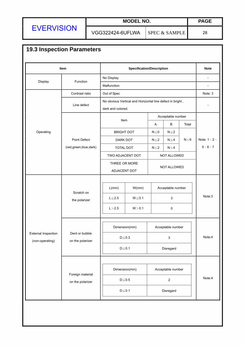
19.3 Inspection Parameters
Item Specification/Description Note
No Display - Display Function
Malfunction -
Contrast ratio Out of Spec Note: 3
Line defect No obvious Vertical and Horizontal line defect in bright ,
dark and colored. -
Acceptable number Item
A B Total
BRIGHT DOT N≦0 N≦2
DARK DOT N≦2 N≦4
TOTAL DOT N≦2 N≦4
N≦6
TWO ADJACENT DOT NOT ALLOWED
Operating
Point Defect
(red,green,blue,dark)
THREE OR MORE
ADJACENT DOT NOT ALLOWED
Note: 1、2、
5、6、7
Scratch on
the polarizer
L(mm) W(mm) Acceptable number
L≦2.5 W≦0.1 3
L>2.5 W>0.1 0
Note:3
Dent or bubble
on the polarizer
Dimension(mm) Acceptable number
D≦0.3 3
D≦0.1 Disregard
Note:4 External Inspection
(non-operating)
Foreign material
on the polarizer
Dimension(mm) Acceptable number
D≦0.5 2
D≦0.1 Disregard
Note:4

MODEL NO. PAGE EVERVISION
VGG322424-6UFLWA SPEC & SAMPLE 29
Note1. Distance between point defect distance should be large than 5 mm. Note2. The definition of dot defect : The dot defect was judged after repair and the size of a defective dot over 1/2 of whole dot is regarded as one defective dot. Note3.
W
L Note4. D:Diameter D=(a+b)/2
Note5. Bright dot is defined through 6% transmission ND Filter as following.
Note6. ADJACENT DOT

MODEL NO. PAGE EVERVISION
VGG322424-6UFLWA SPEC & SAMPLE 30
Note7.
18.4. Handling of LCM (1)Don't give external shock. (2)Don't apply excessive force on the surface. (3)Liquid in LCD is hazardous substance. Must not lick and swallow. when the liquid is
attach to your hand, skin, cloth etc. Wash it out thoroughly and immediately. (4)Don't operate it above the absolute maximum rating. (5)Don't disassemble the LCM.
B:BM
A:AA