Embed Size (px)
Citation preview

National Aeronautics and Space Administration
1
NISOI
Orbital Debris Characterization via Laboratory Optical MeasurementsUnclassified
Heather Cowardin, Ph.D.Orbital Debris Research & Science Operations
ESCG\[email protected]
https://ntrs.nasa.gov/search.jsp?R=20110015594 2018-07-17T07:57:21+00:00Z

National Aeronautics and Space Administration
2
Agenda
• Optical Measurement Center (OMC) overview
• Ongoing tasksI. Rocket body investigationsII. Phase functionsIII. Fragmentation debris characterization (photometric and spectral data)IV. Development of Optical Size Estimation Model (OSEM)
Cowardin
National Aeronautics and Space Administration
3
Introduction
Optical observations of orbital debris offer insights that differ from radar measurements(specifically the size parameter, wavelength regime, and altitude range). For example, time-dependent photometric data yield lightcurves in multiple bandpasses that aid in materialidentification and possible periodic orientations. These data can also be used to help identifyshapes and optical properties at multiple phase angles. Capitalizing on optical data productsand applying them to generate a more complete understanding of orbital space objects is a keyobjective of NASA’s Optical Measurement Program, and the primary reason for the creation ofthe Optical Measurements Center (OMC). The OMC attempts to emulate space-basedillumination conditions using equipment and techniques that parallel telescopic observations andsource-target-sensor orientations.

National Aeronautics and Space Administration
4
Equipment
The OMC consists of the following principle instruments:
• ASD field spectrometer: high-resolution reflectance spectrometer with a range from 300-2500 nm .
• SBIG CCD camera (1024x1536 pixels); attached filter wheel uses Johnson/Bessell blue, visible, red, and infrared filters.
• Newport 75 W Xenon arc lamp used to simulate the solar illumination through the spectral range of 200 to 2500 nm.
• ST robotics R17 robotic arm (on long-term loan from Boeing)
• ESCG custom-built rotary arm with potentiometer
National Aeronautics and Space Administration
5
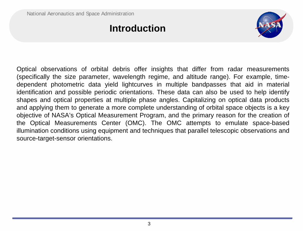
OMC Layout
National Aeronautics and Space Administration
6
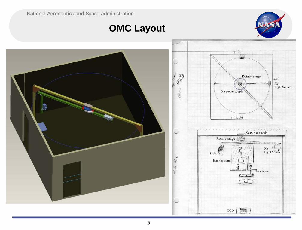
OMC Layout
Light source
Light source power supply
Aluminum optical rails
Gear box with potentiometer
Static steel beam

National Aeronautics and Space Administration
7
Task I. Rocketbody lightcurves
• Active Debris Removal task to help remediate the LEO environment.
• Start with observations of specific rocketbodies to acquire tumble rates
• Using scaled models of the specific rocketbody, photometric lightcurves can be acquired in laboratory for comparison to telescopic data
• First scaled model is SL-8 second stage with a simple, gray color scheme
– Scaled rocketbody will be studied using different rotation axes and other possible observation sampling methods
• Second scaled model will also be SL-8 but painted with commercial (orange/white) color scheme
http://danielmarin.blogspot.com/2010/04/lanzamiento-kosmos-3m-parus-99.html

National Aeronautics and Space Administration
8
Task I. Rocketbody lightcurves

National Aeronautics and Space Administration
9
Task II. Phase functions
• For orbital debris size estimations using optical measurements, a Lambertian phase function is currently assumed:
obs sunM (R) M (R)5.0
0.5g
[ ] 2 Rd 10[ AΨ(α)]π
+−⋅
= ⋅⋅ ⋅
( ) ( ) ( )[ ]2 sin + - cos 23
Ψ(α) α π α απ
= ⋅⋅

National Aeronautics and Space Administration
10
• In 1993, Dr. M. Mulrooney proposed hybrid phase functions as a better fit to observed orbital debris (specular-Lambert combination and Lambert-Lunar).
• Using the OMC with calibrated targets, this phase function identification will be addressed.
– Calibrated targets include spheres and cylinders of different standard materials: pure aluminum and coated Duraflect ®
• Once a “standard” phase function is established for well known Lambertiansurfaces and aluminum surfaces, other materials will be investigated in order to provide a best fit for fragmentation debris.
Task II. Phase functions

National Aeronautics and Space Administration
11
Task III. Fragmentation debris characterization (photometric and spectral data)
1. Characterizing the Orbital Debris Environment– Optical Measurements of debris-like fragments
• Shape investigations• Filter photometry of known materials• Laboratory spectroscopy of returned surfaces, fragmentation debris from hyper-
velocity ground tests, and original equipment manufacture spacecraft materials.
2. Optical characteristics of specific materials• Carbon Fiber Reinforced Plastic (CFRP) is nearly invisible in optical wavelengths• Ground-test impacts with MLI appear to leave a thin film/coating due to the
explosion (possibly adhered material dust particles or soot from the explosion) which significantly decreases its albedo and thus it’s probability of detection in a laboratory, theoretically making it undetectable from ground telescopes
3. Application for telescopic data• In order for the laboratory data to be applicable to all optical users, the
laboratory-based A/m values, color-index, and lightcurves must be provided for each target
National Aeronautics and Space Administration
12
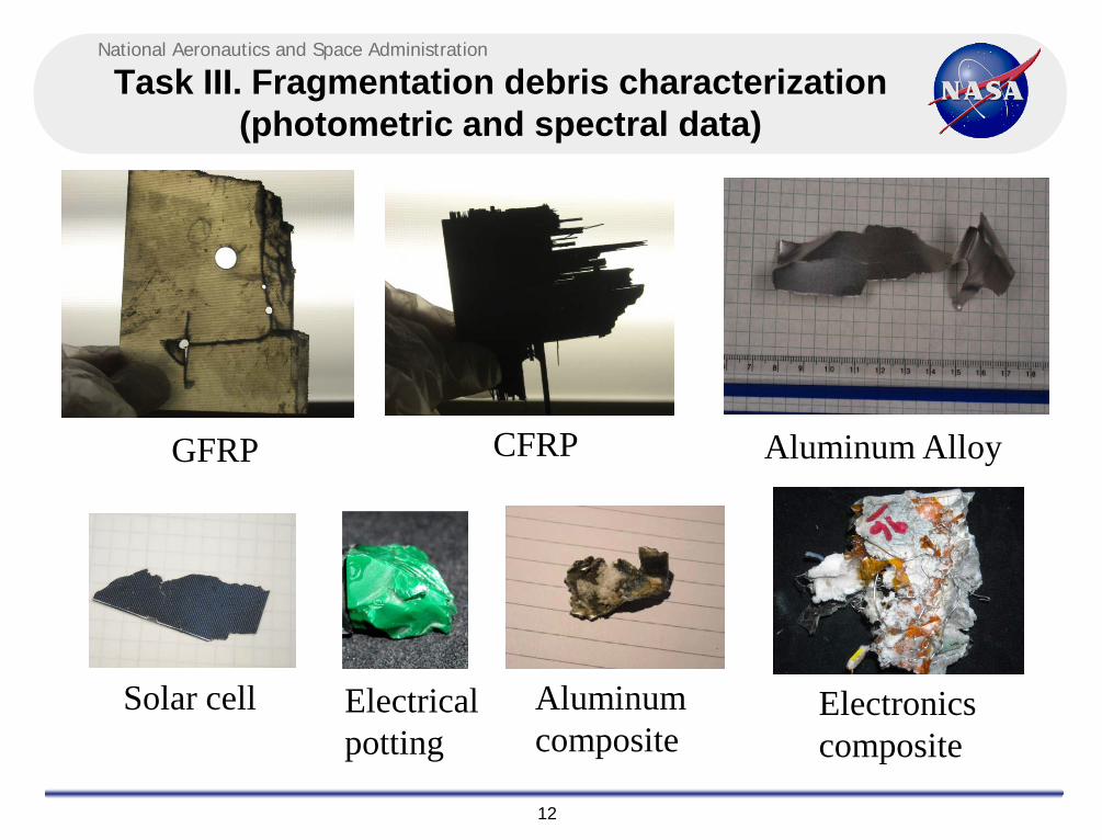
Task III. Fragmentation debris characterization (photometric and spectral data)
GFRP CFRP Aluminum Alloy
Solar cell Electrical potting
Aluminum composite
Electronics composite

National Aeronautics and Space Administration
13
ID Material SourceSize:
Lc(mm)
Mass (kg) ~ A/m (m2/kg)
1 Intact MLI Colleague 57.2 1.2 x 10⁻³ 2.1
2 Layer MLI: Space-facing Kapton Colleague 58.2 3.9 x 10⁻⁴ 5.4
3 Layer MLI: Spacecraft-facing Kapton Colleague 57.6 5.1 x 10⁻⁴ 4.2
4 Impacted MLI Kyushu University 83.8 1.2 x 10⁻³ 5
5 Solar panel Jet Propulsion Laboratory ~60 5.2 x 10⁻³ 0.5
6 Intact Solar cell Spectrolab 50.1 4.4 x 10⁻³ 0.4
7 Fragment Solar cell Kyushu University 23.8 3.1 x 10⁻⁴ 1
8 Aluminum ESOC2 56.5 2.6 x 10⁻³ 1
9 Glass Fiber Reinforced Plastic Kyushu University 95.9 1.7 x 10⁻² 0.4
10 Carbon Fiber Reinforced Plastic Kyushu University 66.3 3.2 x 10⁻³ 1
11 Nugget – Electronic Potting Material SOCIT4 17.7 1.3 x 10⁻³ 0.3
12 Electronic Circuit Board SOCIT4 49.2 7.1 x 10⁻³ 0.2
13 Flake- Aluminum SOCIT4 22.5 1.0 x 10⁻³ 0.5
14 Potted Electronics SOCIT4 64.0 2.2 x 10⁻² 0.2
Task III. Fragmentation debris characterization (photometric and spectral data)
National Aeronautics and Space Administration
14
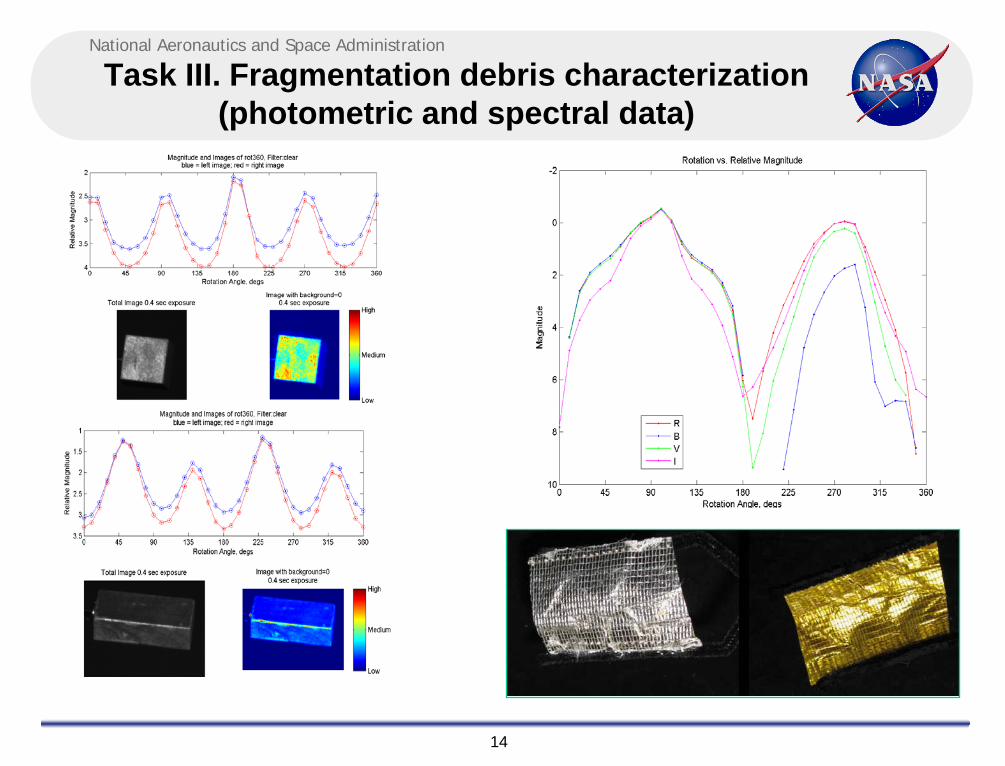
Task III. Fragmentation debris characterization (photometric and spectral data)
National Aeronautics and Space Administration
15
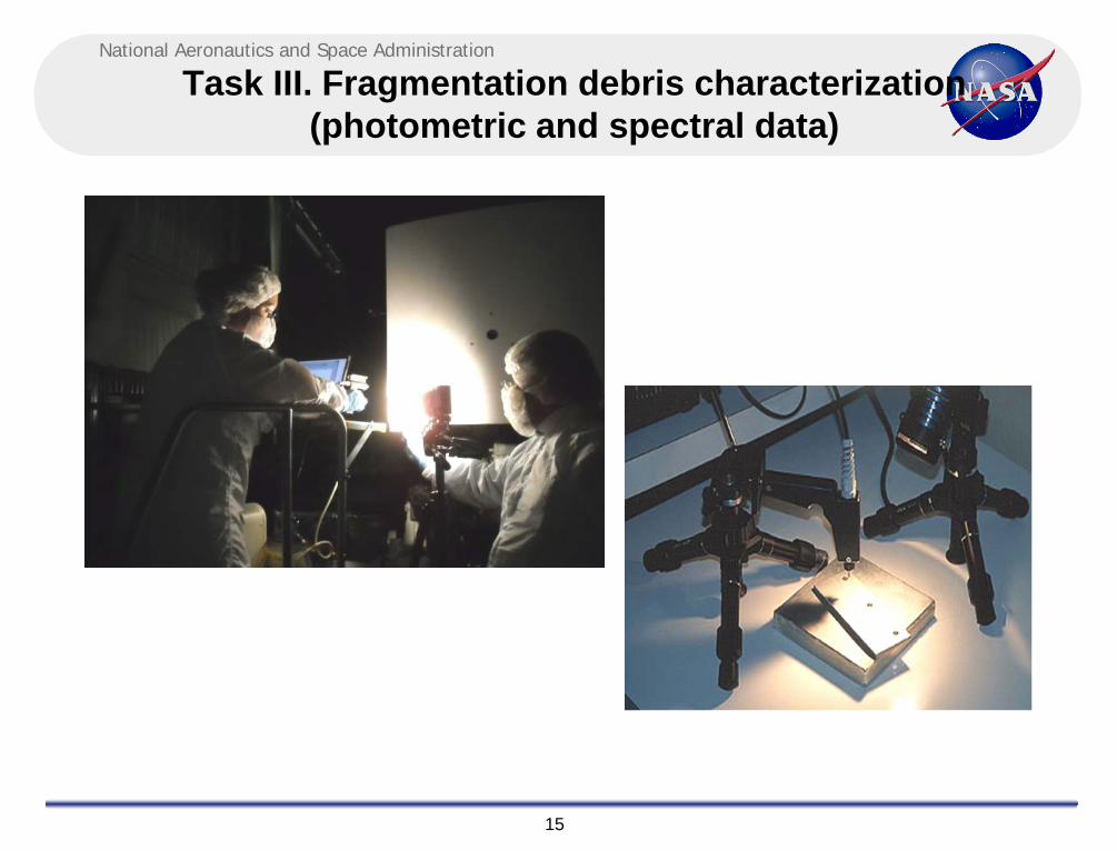
Task III. Fragmentation debris characterization (photometric and spectral data)

National Aeronautics and Space Administration
16
Task III. Fragmentation debris characterization (photometric and spectral data)

National Aeronautics and Space Administration
17
Task IV. Development of Optical Size Estimation Model (OSEM)
• An object’s resultant brightness is dependant on three principal factors: albedo, phase function and illumination aspect angle.
• Overall goal is to define albedo distribution, as it is the dominant factor in brightness determination.
• Laboratory goals:• To define color response of specific materials as a function of rotation of aspect angle and phase
angle.• A low-fidelity BRDF will also be determined in the laboratory• A Spectralon® panel will be used as the white reference• A optical mirror will be used to determine the albedo of different materials
• Using the photometric lightcurve acquisition, spectral data, and phase function investigation, the data will be used to build upon the development of the OSEM.
• OSEM development work will be led by Dr. Matt Hejduk (a.i. solutions); participants include:• Dr. Kira Abercromby (California Polytechnic State University)• Dr. Phillip-Anz-Meader (ESCG\JACOBS)• Dr. Heather Cowardin (ESCG\JACOBS)• Dr. Sue Lederer (NASA)• Dr. Mark Mulrooney (ESCG\MEI)

National Aeronautics and Space Administration
18
Task IV. Development of Optical Size Estimation Model (OSEM)
ID Material Material B-V B-R B-I1 Intact MLI Space-facing, spacecraft-facing +2.0±0.8 +2.9±1.1 +2.5±0.8
2 Layer MLI: Space-facing Kapton Copper Kapton, Aluminized Kapton +3.6±1.0,
-0.1±0.1+2.3±1.3, -0.1±0.2
+3.6±1.7,-0.3±0.6
3 Layer MLI: Spacecraft-facing Kapton Aluminized Kapton, Copper Kapton -0.1±0.1,
+2.1±1.2-0.1±0.1, +2.8±1.7
-0.8±0.5, +2.8±1.1
4 Impacted MLI Layers of copper Kapton sandwiched with Mylar and beta cloth substitute +0.1±0.2 +0.1±0.2 -0.9±1.0
5 Solar panel Solar cell, aluminum honeycomb interior, CFRP backing +1.9±0.1 +2.2±0.3 +0.6±1.0
6 Intact Solar cell Aluminized backing, solar cell +0.2±0.2 +0.1±0.5 -2.3±1.97 Fragment Solar cell Aluminum back, solar cell +0.2±0.2 -0.8±1.0 N/A8 Aluminum Aluminum alloy +0.0±0.0 -0.1±0.1 -0.8±0.4
9 Glass Fiber Reinforced Plastic Glass fiber reinforced plastic +0.1±0.1 + 0.1±0.2 N/A
10 Carbon Fiber Reinforced Plastic Carbon fiber reinforced plastic +0.1±0.1 +0.1±0.0 N/A
11 Nugget - Potting Material Plastic potting material +0.4±0.1 -1.3±0.8 N/A12 Electronic Circuit Board Plastic back side, electronics +0.3±0.1 +0.1±0.3 -3.0±0.5
13 Flake- Aluminum Possible aluminum with unknown surface contaminants +0.0±0.0 +0.1±0.0 -0.6±0.4
14 Potted Electronics Metals and plastics +0.3±0.1 +0.5±0.1 +0.5±0.1
National Aeronautics and Space Administration
19
Back-Up Slides
National Aeronautics and Space Administration
20
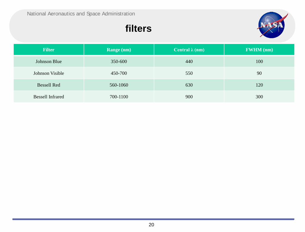
filters
Filter Range (nm) Central λ (nm) FWHM (nm)
Johnson Blue 350-600 440 100
Johnson Visible 450-700 550 90
Bessell Red 560-1060 630 120
Bessell Infrared 700-1100 900 300
National Aeronautics and Space Administration
21
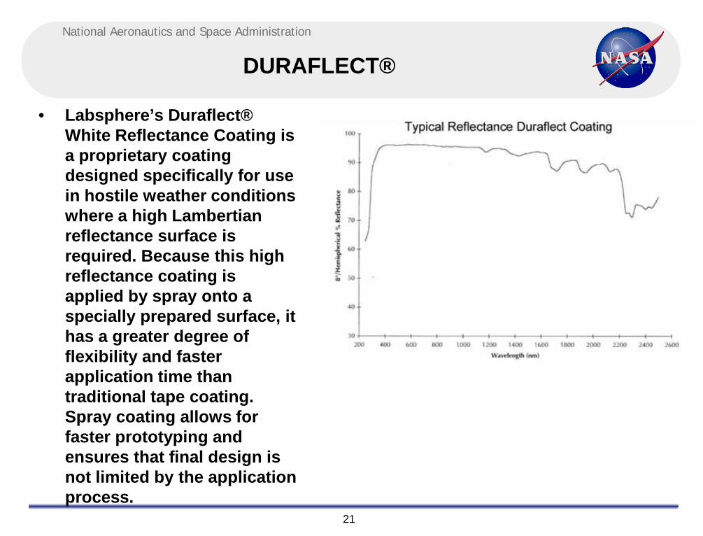
DURAFLECT®
• Labsphere’s Duraflect® White Reflectance Coating is a proprietary coating designed specifically for use in hostile weather conditions where a high Lambertianreflectance surface is required. Because this high reflectance coating is applied by spray onto a specially prepared surface, it has a greater degree of flexibility and faster application time than traditional tape coating. Spray coating allows for faster prototyping and ensures that final design is not limited by the application process.

National Aeronautics and Space Administration
22
OMC objective
The OMC was designed in 2005 in order to obtain the following optical characteristics of orbital debris:
• Generate lightcurves:– Shape analysis– Comparison to telescopic data– Model real-scaled rocket-bodies to determine tumble axis (Liou)
• Acquire filter photometry:– Insight to material characteristics relative to telescopic data– Provide comparisons between laboratory and telescopic data via color index data
• Investigate phase functions– Current assumption follows Lambertian sphere assumption – Lab allows for comparisons to how debris-like fragments follow this phase function (follow-up to Mulrooney’s thesis that
suggested Hybrids may be a better fit)• Acquire laboratory spectroscopy:
– Provides truth data for materials– Expanding NASA spectral database to include more modern materials which previously were not available (Abercromby)
• Provide insight to material risk & analysis – Able to provide optical characteristics of specific materials relative to risk of impact
• Ie, carbon fiber reinforced plastic is nearly invisible in optical wavelengths, possible to paint white for use in future spacecraft• Ie, ground-test impacts with MLI appear to have a film/coating due to explosion which minimizes reflectance and thus it’s probability
of detection remotely if the same film is also adhered to in space-explosions/collisions• Ie, Known A/m values, color-index, lightcurves to compare with remote data of unknown targets, application for all optical users is
characterizing orbital debris environment
• Develop an albedo distribution/Optical Size Estimation Model– Work towards defining an albedo distribution for the current fragments to relate to actual space debris– This distribution will be built into modeling the first optical Size Estimation Model