Embed Size (px)
Citation preview

Index D2
Pressure Gauges D4
PPC Series D13
Laser Particle Counters D38
Sensors and Switches D54
The STAUFF Diagtronics programme provides components and services for monitoring and analysing hydraulic fl uids in mobile and industrial hydraulic systems.The range includes analog stainless steel pressure gauges to high-quality, high-end laser particle counters.
A versatile range is essential for different customer needs. The innovative STAUFF Diagtronics programme addresses these decisive factors in the market and offers a wide range of state of the art products with the highest quality.
DDiagtronics
Competent and fast service is a matter of course in our company. All products undergo the relevant tests following international standards, and are subject to our in-house quality management in accordance with EN ISO 9001:2008.
Due to the extensive inventory, both customized special parts and special product combinations are available.
Please contact STAUFF for further details.
www.stauff.com
Diag
tron
ics
D
NoAm Version Diagtronics January 2013.indd 1 22.01.2013 11:39:20

D2 www.stauff.com
Index
Introduction D4
Information on the Pressure Equipment Directive
D5
Accessories for Pressure Gauges D5
Pressure Gauge (Analog) SPG D6
Pressure Gauge (Digital) SPG-DIGI D8
Pressure Gauge (Digital) Wireless SPG-DIGI-W D9
Pressure Test Kit (Analog)Multi Gauge Kit (Analog)
SMB D10
Pressure Test Kit (Digital) SMB-DIGI D11
Accessories (Connection Adaptors) D11
PPC SeriesPressure Gauges (Analog and Digital)
Introduction D13
Overview D14
Functional Block Diagram D15
Hydraulic Tester PPC-04/2 D16
Hydraulic Tester PPC-06/08-plus D17
Pressure Sensor PPC-04/12-PT/2 D18
Temperature SensorPPC-04/12-TSPPC-04/12-TSH
D19
Rotational Speed Sensor PPC-04/12-SDS-CAB D20
Flow Turbine PPC-04/12-SFM D21
Gear Flow Meter PPC-04/12-SVC D22
Miscellaneous MeasurementsD24
Cables / Adaptors / Accessories D25
Complete SystemsPPC-04/2PPC-06/08-plus
D26
Hydraulic Test Equipment D27
Hydraulic Tester PPC-Pad D28
Complete Systems PPC-Pad-SET D29
CAN Pressure Sensor PPC-CAN-PT D33
CAN Flow Turbine PPC-CAN-SFM D34
CAN Connection CablesPPC-CAN-CAB2PPC-CAN-CAB-YPPC-CAN-R
D35
CAN Frequency Converter PPC-CAN-FR D35
CAN Hydraulic Test Equipment D36
ZERO
IN1=IN2
REC
OK
STOP
ESC
DISP
LINE
RESET
MIN/MAX
MEM
SET
NoAm Version Diagtronics January 2013.indd 2 22.01.2013 11:40:40

Diag
tron
ics
D
www.stauff.com D3
Index
Introduction D38
Overview D38
Features & Options (General) D39
LasPaC II - Portable LasPaC II-P D40
LasPaC II - Mobile LasPaC II-M D42
LasPaC II - Inline LasPaC II-I D44
Bottle Sampler UnitsBottle Sampler 110Bottle Sampler 250Bottle Sampler 250-E
D46
Accessories D47
Laser Particle Monitor LPM-1 D50
Laser Particle Transducer LPT-1 D51
Laser Interface Module LIM D52
Dynamic Application Valve DAV D52
Check Oil AnalysisOil Sampling Kit
STFCSFSK
D53
Laser Particle Counters
Introduction D54
Level-Temperature Switch SLTS D55
Level-Temperature Switch Aluminium SLTSA D56
Level-Temperature Switch Display SLTSD D57
Pressure Switch SPW D58
Pressure Switch SPW-SD D59
Pressure Transmitters SPT D60
Pressure Transmitters PT D64
Pressure Switch and Transmitter SPWF D68
Temperature Switch and Transmitter STWE D72
Temperature Transmitter STC D74
Temperature Switch STW D76
Flowtell Inline Flow Meter SFF D77
Flow IndicatorSDMSDMKR
D78
Flow Monitoring System SGF D80
Flow Monitoring System SGFE D86
Flow Rate Measuring Display STD D89
Sensors and Switches
NoAm Version Diagtronics January 2013.indd 3 22.01.2013 11:43:03
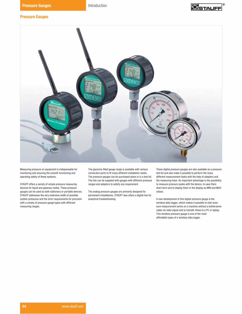
Measuring pressure on equipment is indispensable for monitoring and ensuring the smooth functioning and operating safety of these systems.
STAUFF offers a variety of simple pressure measuring devices for liquid and gaseous media. These pressure gauges can be used as both stationary or portable devices. STAUFF addresses the very extensive width of possible system pressures and the strict requirements for precision with a variety of pressure gauge types with different measuring ranges.
������������ ���������������������������������������������������������� �����������������������������������The pressure gauges can be purchased alone or in a test kit. The kits can be supplied with gauges with different pressure ranges and adaptors to satisfy any requirement.
The analog pressure gauges are primarily designed for permanent installations. STAUFF also offers a digital line for analytical troubleshooting.
These digital pressure gauges are also available as a pressure test kit and also make it possible to perform the many different measurement tasks with the help of adapters and the measuring hose. An important advantage is the possibility to measure pressure peaks with the device, to save them short term and to display them in the display as MIN and MAX values.
A new development of this digital pressure gauge is the wireless data logger, which makes it possible to start pres-sure measurement series on a machine without a bothersome cable via radio signal and to transfer these to a PC or laptop. This wireless pressure gauge is one of the most affordable types of a wireless data logger.
Pressure Gauges
Pressure Gauges Introduction
D4 www.stauff.com

Diag
tron
ics
D
Introduction Pressure Gauges
www.stauff.com D5
Pressure Gauges � Accessories
Single Station Gauge Isolator Valve(see Valves section)
Multi Station Gauge Isolator Valve(see Valves section)
Gauge Isolator Needle Valves(see Valves section)
Test Hoses - Gauge Adaptor(see STAUFF Test section)
Gauge Adaptor(see STAUFF Test section)
Direct Gauge Adaptor(see STAUFF Test section)
Adjustable Gauge Fitting(see STAUFF Test section)

D6 www.stauff.com
Pressure Gauges Product Information / Order Codes
Product Description
Area of Application� Mechanical pressure measurement
Features
� Suitable for hydraulic oil and gaseous media compatible with copper based alloys
� Available in nominal sizes 63 and 100 mm / 2.5 and 4 in� Thread form: for BSP (G1/4 and G1/2),
NPT (1/4 NPT and 1/2 NPT), SAE (7/16–20 UNF)� Stainless Steel (1.4301) housing� Acrylic sight glass� �������� ����� Standard dual scales with pressure indication in bar and PSI� ��������������������������������!����� Bezel type: crimped
Note: Please consult STAUFF before you use SPG with other media.
Options
� 316 Stainless Steel connector wetted parts� Protective rubber cap� Additional scale readings including private label� ������������������������������������������������������
as spare parts � Other diameters upon request (40 mm, 50 mm, 150 mm)
Technical Data
� Pressure gauge according to EN 837-1� "��#������������������ ������
AccuraciesSPG-063: ± 2/1/2% of span (ASME B40.100 Grade A) SPG-100: 1% of span (ASME B40.100 Grade 1A)
Permissible Temperatures� Ambient: -20 °C ... +60 °C / -4 °F ... +140 °F� Media: max. +60 °C / max. +140 °F
Protection Ratings � IP 65: for all manometer SPG 100 and SPG 063 > 16 bar / 232 PSI IP 65 protection rating: Dust tight and protected against water jets
� IP 54 for all manometer SPG 063 � � � $�&'����*�9;9�<"=���������������� compensation opening IP 54 protection rating: Dust protected and protected against splashing water
Pressure Gauge (Analog) Type SPG (Stem Mounting)
Order Codes
Pressure Gauge (Analog) Type SPG (Panel Mounting)
Pressure Gauge (Analog) � Type SPG
For further information on this product, please see page B34, STAUFF Test section.
063 - 00030 - 05 - P - N04 - U - 063 063 SPG 00030 00030 05 05 P P N04 N04 U U
� Adaption Stem mounting S Panel mounting P
� Process Connection G1/4 (only SPG 063) B04 G1/2 (only SPG 100) B08 1/4 NPT (only SPG 063) N04 1/2 NPT (only SPG 100) N08
7/16–20 UNF (only SPG 063) U04 Note: Others on request.
� Accessories No accessory (none) U-bolt assembly U ?�������������������@�������������������H F J����������������� R ������������������������������
(for panel mount only) UF
"������� ���� S
� Accessories (for Stem Mount only) Protective rubber cap G
� Connection Material & Wetted Parts Brass connection and copper alloy wetted parts (none) 316 Stainless Steel connection and wetted parts W5
Spare Parts Rubber boot, black SPG 063-RBB
U-bolt kit SPG 063-U?������������� SPG 063-FU-bolt kit SPG 100-U?������������� SPG 100-F
* FS = Full Scale
� Series and Type Stainless Steel Pressure Gauge SPG
� Size 63 mm, with G1/4, 1/4 NPT 063
or 7/16–20 UNF connection 100 mm, with G1/2 or 1/2 NPT 100
� Pressure Ranges -1,02 ... 0 bar / -30 inHg ... 0 PSI 30HG30 -1,02 ... 2,07 bar / -30 inHg ... 30 PSI 03030 0 ... 2,07bar / 0 ... 30 PSI 00030 0 ... 4,14 bar / 0 ... 60 PSI 00060 0 ... 6,89 bar / 0 ... 100 PSI 00100 0 ... 11,03 bar / 0 ... 160 PSI 00160 0 ... 13,79 bar / 0 ... 200 PSI 00200 0 ... 20,68 bar / 0 ... 300 PSI 00300 0 ... 34,74 bar / 0 ... 500 PSI 00500 0 ... 41,37 bar / 0 ... 600 PSI 00600 0 ... 68,95 bar / 0 ... 1000 PSI 01000 0 ... 103,42 bar / 0 ... 1500 PSI 01500 0 ... 137,90 bar / 0 ... 2000 PSI 02000 0 ... 206,84 bar / 0 ... 3000 PSI 03000 0 ... 275,79 bar / 0 ... 4000 PSI 04000 0 ... 344,74 bar / 0 ... 5000 PSI 05000 0 ... 413,69 bar / 0 ... 6000 PSI 06000 0 ... 517,11 bar / 0 ... 7500 PSI 07500 0 ... 689,48 bar / 0 ... 10000 PSI 10000 Note: Others on request. Information always refer to the pressure setting of the outside scale.
Styles of Scales bar / PSI (bar outside/PSI inside - standard option) 01 bar 02 PSI 03 PSI / bar (PSI outside/ bar inside) 05 kPa / PSI (kPa outside/ PSI inside) 10 Note: Others on request.
Diag
tron
ics
D
www.stauff.com D7
Dimensions Pressure Gauges
ØA
B
ØD H
C
E
F
Hex14
ØA
ØB
E
F
ØD
G
C
ØC
Hex14
SPG 063 ... S ... SPG 063 ... P ... U
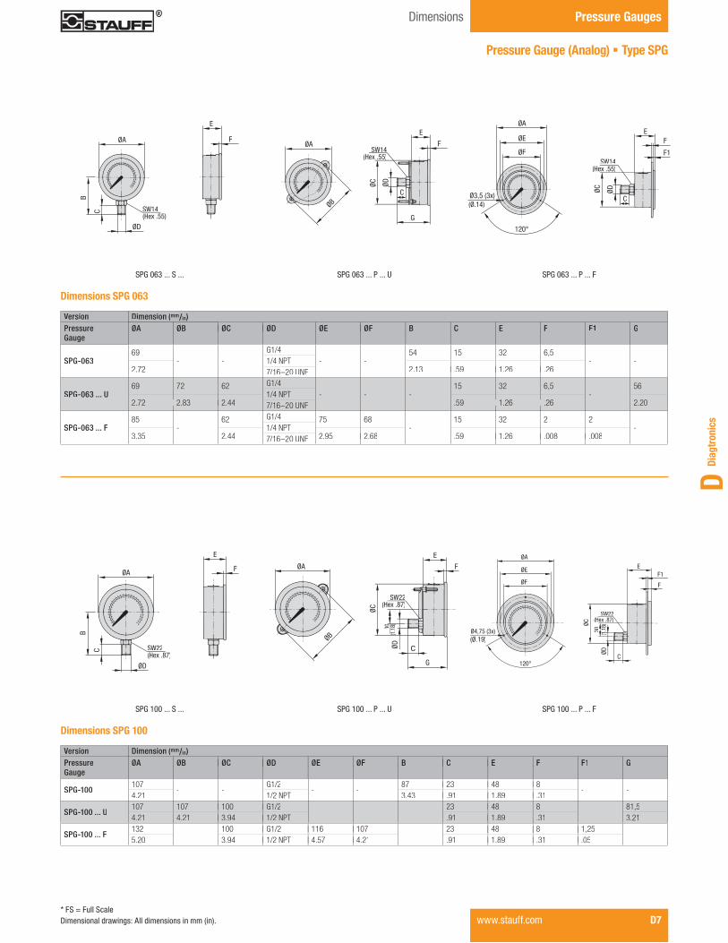
Version Dimension (mm/in)PressureGauge
ØA ØB ØC ØD ØE ØF B C E F F1 G
SPG-06369
- -G1/4
- -54 15 32 6,5
- -1/4 NPT2.72 2.13 .59 1.26 .267/16–20 UNF
SPG-063 ... U69 72 62 G1/4
- - -15 32 6,5
-56
1/4 NPT2.72 2.83 2.44 .59 1.26 .26 2.207/16–20 UNF
SPG-063 ... F85
-62 G1/4 75 68
-15 32 2 2
-1/4 NPT3.35 2.44 2.95 2.68 .59 1.26 .008 .0087/16–20 UNF
Dimensions SPG 063
ØA
E
F
HØD
B
C Hex22 ØD
E
F
ØB
30
G
C
ØA
ØC
Hex22
SPG 100 ... S ... SPG 100 ... P ... U
Dimensions SPG 100
Ø3,5 (3x)
120°
ØC
ØD
E
F1
ØA
ØE
ØF
C
F
Hex14
SPG 063 ... P ... F
ØA
ØE
ØF
Ø4,75 (3x)
E
F
F1
120°
C
ØD
30
ØC
Hex22
SPG 100 ... P ... F
Version Dimension (mm/in)PressureGauge
ØA ØB ØC ØD ØE ØF B C E F F1 G
SPG-100107
- -G1/2
- -87 23 48 8
- -4.21 1/2 NPT 3.43 .91 1.89 .31
SPG-100 ... U107 107 100 G1/2
- - -23 48 8
-81,5
4.21 4.21 3.94 1/2 NPT .91 1.89 .31 3.21
SPG-100 ... F132
-100 G1/2 116 107
-23 48 8 1,25
-5.20 3.94 1/2 NPT 4.57 4.21 .91 1.89 .31 .05
Pressure Gauge (Analog) � Type SPG
* FS = Full ScaleDimensional drawings: All dimensions in mm (in).
SW14SW14(Hex .55)
SW14SW14(Hex .55))
SW14SW14(Hex .55))
(Ø.14)
SW22SW22(Hex .87)
SW22SW22(Hex .87)
30(1
.18)
(
SW22SW22(Hex .87)(H
3030 (1.1
8)
(Ø.19)

Pressure Gauge (Digital) � Type SPG-DIGI
Product Description
The SPG-DIGI Digital Pressure Gauges are intended to measure and display pressures in hydraulic systems, particularly for oils, lubricants and water. They can display the current measured values, as well as minimum and maximum values, with an accuracy of 0,5 % offull scale.
The SPG-DIGI Digital Pressure Gauges are available individually, or as part of a complete pressure test kit.They are very sturdy, reliable, easy to use and come with the CE mark (evidence of conformity compliance).
Features
� Bar graph display (drag indicator)� Background lighting� Zero correction� Battery charge display
- DIGI - B0016 - U - DIGI DIGI SPG B0016 B0016 U U CAL
Process Connection G1/4 B 7/16–20 UNF U
� Calibration ����������� ������ ����� (none) �������� ������ ����� CAL
Order Codes
Version Pressure Range (bar/r PSI// ) Maximum Pressure (bar/r PSI// ) Burst Pressure (bar/r PSI// )
B0016-1 ... 16 40 50-14.5 ... 232 580 725
B01000 ... 100 200 8000 ... 1450 2900 11603
B04000 ... 400 800 17000 ... 5801 11603 24656
B06000 ... 600 1200 22000 ... 8702 17404 31908
Pressure Ranges
Technical Data Materials� Housing made of die-cast Zinc with
TPE rubber protective covering� Adaptor made of Steel, zinc-nickel coated� Gaskets: NBR (Buna-N®)
FPM (Viton®) or EPDM upon request
Dimensions and Weight� Diameter: 79 mm / 3.11 in� Depth: 33 mm / 1.30 in� Weight: 540 g / 1.19 Ibs
Display� Text display 4 1/2-digit � Size: 50 x 34 mm / 1.97 x 1.34 in� Actual value display: 15 mm / .59 in� MIN-/MAX or FS* display: 8 mm / .31 in� Units: bar, PSI, Mpa, kPa, mbar� Peak pressure measurement with 10 ms sampling rate� Lighted measured value display
Accuracy� ±0,25 % FS* typ. / ±0,5 % FS* max.� Resolution: 4096 steps
Permissible Temperatures� Ambient: -10 °C ... +50 °C / +14 °F ... +122 °F� Media: -20 °C ... +80 °C / -4 °F ... +176 °F� Storage: -20 °C ... +60 °C / -4 °F ... +140 °F
� Relative humidity: < 85 %� Battery life: max. 1500 hours
(operating without lighting, 2 x 1,5 V DC AA (LR6-AA)Alkaline Mignon)
Process Connections� G1/4 or 7/16–20 UNF made of 1.4404 Stainless Steel
� Vibration: IEC 60068-2-6 / 10 ... 500 Hz / 5 g� Shock: IEC 60068-2-27 / 11 ms / 25 g� Load cycles (106): 100
� Series Pressure Gauge SPG
� Type Digital pressure measurement and display DIGI
� Pressure Ranges -1 ... 16 bar / -14.5 ... 232 PSI B0016 0 ... 100 bar / 0 ... 1450 PSI B0100 0 ... 400 bar / 0 ... 5801 PSI B0400 0 ... 600 bar / 0 ... 8702 PSI B0600
Protection Rating� IP 67 protection rating: Dust tight and protected against
powerful water jets; even immersion (up to 1 m / 3.28 ft) ������ ����������������� ���������������������� ���� �and time
* FS = Full Scale
Pressure Gauges Product Information / Order Codes
D8 www.stauff.com

Diag
tron
ics
D
Pressure Gauge (Digital) Wireless � Type SPG-DIGI-W
Product Description
����������������������������������� ����� ��������������������digital pressure measuring, the new Wireless Digital Pressure Gauge (SPG-DIGI-W) is now available, allowing a most precise measurement and wireless transmission of values to a PC or notebook.With its compact design and the ease of operation, theSPG-DIGI-W is actually a single channel wireless data logger.With just a single PC adaptor, you can simultaneously transmit measured values of up to 16 digital pressure gauges over a distance of max. 50 m /164.04 ft to your computer.
���������� ����������������������������������������� �machinery and equipment can be easily accomplished from your desk, thus allowing the direct evaluation and storage ofthe measured values. Please note that measured values can-not be displayed in real time.
Features
� Bar graph display (drag indicator)� Background lighting � Zero correction� Battery charge display� Wireless data logging
PC adaptor SPG-DIGI-W-PC only includedaptor SPG-DIGI-W-PC only includedin the SMB-DIGI-W Pressure Test Kit
- DIGI-W - B0016 - U - DIGI-W DIGI-W B0016 B0016 SPG U U CAL
Process Connection G1/4 B 7/16–20 UNF U
� Calibration ����������� ������ ������ (none) �������� ������ ������� CAL
Order Codes
Version Pressure Range (bar/r PSI// ) Maximum Pressure (bar/r PSI// ) Burst Pressure (bar/r PSI// )
B0016-1 ... 16 40 50-14.5 ... 232 580 725
B01000 ... 100 200 8000 ... 1450 2900 11603
B04000 ... 400 800 17000 ... 5801 11603 24656
B06000 ... 600 1200 22000 ... 8702 17404 31908
Pressure Ranges
Technical Data
Materials� Housing made of die-cast Zinc with
TPE rubber protective covering� Adaptor made of Steel, zinc-nickel coated� Gaskets: NBR (Buna-N®)
FPM (Viton®) or EPDM upon request
Dimensions and Weight� Diameter: 79 mm / 3,11 in� Depth: 33 mm / 1,30 in� Weight: 540 g / 1,19 Ibs
Display� Text display 4 1/2-digit � Size: 50 x 34 mm / 1.97 x 1.34 in� Actual value display: 15 mm / .59 in� MIN-/MAX or FS* display: 8 mm / .31 in� Units: bar, PSI, Mpa, kPa, mbar� Peak pressure measurement with 10 ms sampling rate� Lighted measured value display
Accuracy� ±0,25 % FS* typ. / ±0,5 % FS* max.� Resolution: 4096 step
Permissible Temperatures� Ambient: -10 °C ... +50 °C / +14 °F ... +122 °F� Media: -20 °C ... +80 °C / -4 °F ... +176 °F� Storage: -20 °C ... +60 °C / -4 °F ... +140 °F
� Relative humidity: < 85 %� Battery life: max. 800 hours
(operating without lighting, 2 x 1,5 V DC AA (LR6-AA)Alkaline Mignon)
Process Connections� G1/4 or 7/16–20 UNF made of 1.4404 Stainless Steel
� Vibration: IEC 60068-2-6 / 10 ... 500 Hz / 5 g� Shock: IEC 60068-2-27 / 11 ms / 25 g� Load cycles (106): 100
� Series Pressure Gauge SPG
� Type Digital pressure measurement
and display (wireless) DIGI-W
� Pressure Ranges -1 ... 16 bar / -14.5 ... 232 PSI 0016 0 ... 100 bar / 0 ... 1450 PSI 0100 0 ... 400 bar / 0 ... 5801 PSI 0400 0 ... 600 bar / 0 ... 8702 PSI 0600
PC Functions� Read-out data from measured data memory via a radio
interface (2,4 GHz)� Measuring over a distance of max. 50 m / 164.04 ft� ��!���������� �����������������
Memory Functions� 5000 measurement values (MAX pressure peaks)� Setup of storage interval� Time based recording� Pressure spike monitoring
Protection Rating� IP 67 protection rating: Dust tight and protected against
powerful water jets; even immersion (up to 1 m / 3.28 ft) ������ ����������������� ����������������������� ���� ��and time
* FS = Full Scale www.stauff.com D9
Pressure GaugesProduct Information / Order Codes

Pressure Test Kit (Analog) � Type SMB
Product Description
In addition to the individual SPG gauges, the STAUFF Pressure Gauges are also available as part of a pressure test kit. The SMB Pressure Test Kits are assembled in various versions,in accordance with customer wishes. All pressure test kits are supplied in a handy case with custom-designed foam inserts.
For further information on this product please see page B35, STAUFF Test section.
Pressure Gauges Product Information
Components
Standard Option SMB20-A1� 1x Hose assembly (60 in): SMS20-1524mm-B� 1x Direct gauge adaptor 1/4 NPT: SMD20-1/4NPT-C6F� 1x Union: SSV20-C6F� 1x Pressure gauge 7500 PSI: WPG-063-07500-5-S-N04� 2x Test coupling 1/8 NPT: SMK20-1/8NPT-VD-C6F� 3x Test coupling 1/4 NPT: SMK20-1/4NPT-VD-C6F� 2x Test coupling 7/16 UNF: SMK20-7/16UNF-VE-C6F� 2x Test coupling 9/16 UNF: SMK20-9/16UNF-VE-C6F� "�� ��!���#$���������"&'�>?�@��#$JQ'>�JY
Standard Option SMB20-B1� 1x Hose assembly (60 in): SMS20-1524mm-B� 2x Direct gauge adaptor 1/4 NPT: SMD20-1/4NPT-C6F� 1x Union: SSV20-C6F� 1x Pressure gauge 7500 PSI: WPG-063-07500-5-S-N04� 1x Pressure gauge 1000 PSI: WPG-063-01000-5-S-N04� 2x Test coupling 1/8 NPT: SMK20-1/8NPT-VD-C6F� 2x Test coupling 1/4 NPT: SMK20-1/4NPT-VD-C6F� 1x Test coupling 7/16 UNF: SMK20-7/16UNF-VE-C6F� 1x Test coupling 9/16 UNF: SMK20-9/16UNF-VE-C6F� "�� ��!���#$���������"&'�>?�@��#$JQ'>�JY
Standard Option SMB20-C1� 2x Hose assembly (60 in): SMS20-1524mm-B� 3x Direct gauge adaptor 1/4 NPT: SMD20-1/4NPT-C6F� 2x Union: SSV20-C6F� 1x Pressure gauge -30 inHg ... 30 PSI: WPG-063-03030-5-S-N04� 1x Pressure gauge 7500 PSI: WPG-063-07500-5-S-N04� 1x Pressure gauge 1000 PSI: WPG-063-01000-5-S-N04� 2x Test coupling 1/8 NPT: SMK20-1/8NPT-VD-C6F� 2x Test coupling 1/4 NPT: SMK20-1/4NPT-VD-C6F� 1x Test coupling 7/16 UNF: SMK20-7/16UNF-VE-C6F� 1x Test coupling 9/16 UNF: SMK20-9/16UNF-VE-C6F� "�� ��!���#$���������"&'�>?�@��#$JQ'>�JY
Pressure Gauge Kit - Type SMB20-A1 Pressure Gauge Kit - Type SMB20-B1 Pressure Gauge Kit - Type SMB20-C1
Pressure Test Kit (Analog) � Multi Gauge Kit � Type SMB20-E1
Product Description
The SMB20-E1 multi-gauge kit is available preassembledand includes a variety of pressure gauges, test points, gaugeadaptors, test hoses and more. The gauges, test points and adaptors are enclosed in protective foam. The test hoses are secured in a removable zipper pouch.All of these components are encased in a single durableprotective enclosure.� Y����!�[���� ����������������������� �������������� \]^������ ���� �������������_��������� ������������
as an after market service tool� Custom labels, foam inserts and boxes are available in
quantity
Components
Multi Gauge Kit SMB20-E1-X (see table below for X)� 3x Test coupling 1/4 NPT: SMK20-1/4NPT-VD-C6F� 3x Test coupling 7/16 UNF: SMK20-7/16UNF-VE-C6F� 3x Test coupling 9/16 UNF: SMK20-9/16UNF-VE-C6F� 3x Gauge adaptor: SMA20-1/4NPT-V-C6F� 3x Union adaptor: SSV20/20-C6F� 2x Test hose (12 in): SMS20-305mm-B� 2x Test hose (24 in): SMS20-610mm-B� 2x Test hose (60 in): SMS20-1524mm-B� 1x Swivel run tee -4 JIC: SGV-7/16UNF-04-JIC1/4-F/M� 1x Swivel run tee -6 JIC: SGV-7/16UNF-06-JIC3/8-F/M� 1x Swivel run tee -8 JIC: SGV-7/16UNF-08-JIC1/2-F/M� "�� ��!���#$���������"&'�>?�@��#$JQ'>�JY
SMB20-E1-5 SMB20-E1-6 SMB20-E1-7 SMB20-E1-8SPG-063-03030-5-S-N04 SPG-063-03030-5-S-N04 SPG-063-03030-5-S-N04 SPG-063-03030-5-S-N04SPG-063-00600-5-S-N04 SPG-063-00600-5-S-N04 SPG-063-00600-5-S-N04 SPG-063-00600-5-S-N04SPG-063-03000-5-S-N04 SPG-063-01500-5-S-N04 SPG-063-01500-5-S-N04 SPG-063-01000-5-S-N04SPG-063-05000-5-S-N04 SPG-063-03000-5-S-N04 SPG-063-03000-5-S-N04 SPG-063-01500-5-S-N04
SPG-063-03000-5-S-N04SPG-063-05000-5-S-N04SPG-063-10000-5-S-N04 SPG-063-05000-5-S-N04SPG-063-05000-5-S-N04SPG-063-07500-5-S-N04SPG-063-10000-5-S-N04SPG-063-07500-5-S-N04SPG-063-10000-5-S-N04SPG-063-10000-5-S-N04
Each pressure gauge includes a protective gauge cover SPG-063-RBB and a direct gauge adapter SMD-1/4NPT-C6F
Gauges included in Standard Kit
5 Gauge Kit: see table SMB20-E1-56 Gauge Kit: see table SMB20-E1-67 Gauge Kit: see table SMB20-E1-78 Gauge Kit: see table SMB20-E1-8
D10 www.stauff.com

Diag
tron
ics
D
www.stauff.com D11
Pressure GaugesProduct Information / Order Codes
Pressure Test Kit (Digital) � Type SMB-DIGI /-W
Product Description
Digital Pressure Gauges are also available as part of a pressure test kit. The SMB-DIGI pressure test kits are assembled in various versions, in accordance with customer wishes. All pressure test kits are supplied in a handy case with custom-designed foam inserts.
Along with the SPG-DIGI-W itself, the pressure test kitsalways contain a PC adaptor with USB connection cable (1,5 m / 4.92 ft).
Components
Standard Option SMB-DIGISPG-DIGI digital pressure gauge� SMD adaptor (-4 SAE to M16 x 2 or S12,65 x 1,5)� SSV20 or SSV12 hose connector� SMK20-1/4NPT-VD-C6F or SKK12-1/4NPT-VD-C6F test point� SMK20-1/8NPT-VD-C6F or SKK12-1/8NPT-VD-C6F test point� SMK20-7/16UNF-VE-C6F or SKK12-7/16UNF-VE-C6F test point� SMK20-9/16UNF-VE-C6F or SKK12-9/16UNF-VE-C6F test point� SMS test hose (1,5 m / 4.92 ft) M16 x 2 or S12,65 x 1,5
connection rated to 600 bar / 8702 PSI� SQD-04NF-C Quick disconnect� Operating Instructions (multilingual) on CD
Standard Option SMB-DIGI-W� SPG-DIGI-W digital pressure gauge� PC adaptor SPG-DIGI-W-PC with USB connection� SDA adaptor (G1/4 to M16 x 2 or S12,65 x 1,5)� SSV20 or SSV12 hose connector� SMS test hose (2 m / 6.56 ft), M16 x 2 or S12,65 x 1,5
connection, pressure-resistant to 600 bar / 8702 PSI� Operating instructions and software (multilingual) on CD� Dust cloth
- DIGI - 20 - B0016 - U - DIGI DIGI SMB 20 20 B0016 B0016 U U CAL
Order Codes
Version Pressure Range (bar/r PSI// ) Maximum Pressure (bar/r PSI// ) Burst Pressure (bar/r PSI// )
B0016-1 ... 16 40 50-14.5 ... 232 580 725
B01000 ... 100 200 8000 ... 1450 2900 11603
B04000 ... 400 800 17000 ... 5801 11603 24656
B06000 ... 600 1200 22000 ... 8702 17404 31908
Pressure Ranges
Pressure Ranges B0016 0 ... 100 bar / 0 ... 1450 PSI B0100 0 ... 400 bar / 0 ... 5801 PSI B0400 0 ... 600 bar / 0 ... 8702 PSI B0600
� Process Connection G1/4 B 7/16–20 UNF U
� Calibration ����������� ������ ������ (none) �������� ������ ������� CAL
Pressure Test Kit (Digital) Type SMB-DIGI-W Pressure Test Kit (Digital) Type SMB-DIGIPressure Test Kit (Digital) Type SMB-DIGI-SM
SMD AdaptorConnects the pressure gauge to a test point
SAD AdaptorOnly in conjunction with the SMD20-7/16UNF-C6F adaptor, connects to other test point sizes
Test PointSTAUFF Test or comparable
Adaptor Adaption from to Dimension G
SMD20-7/16UNF-C6F 7/16–20 UNF M16 x 2
SMD15-7/16UNF-C6F 7/16–20 UNF M16 x 1,5
SMD12-7/16UNF-C6F 7/16–20 UNF S12,65 x 1,5
SAD20/15-P-C6F M16 x 2 M16 x 1,5
SAD20/12-P-C6F M16 x 2 S12,65 x 1,5
SAD20/10-P-C6F M16 x 2 Plug-in system
Accessories (Connection Adaptors)
A large number of adaptors are available to connect STAUFF SPG-DIGI and SPG-DIGI-W pressure gauges to other test points and testers. Other adaptors are available.
5.68
SW
G
h
M16 G
M16 x 2 G
� Series Pressure Test Kit SMB
� Types SPG-DIGI digital pressure gauge DIGI SPG-DIGI digital pressure gauge (wireless) DIGI-W SPG-DIGI digital small DIGI-SM
� Adaptor Version Adapts to STAUFF Test 20 (M16 x 2) 20 Adapts to STAUFF Test 12 (S12,65 x 1,5) 12
7/16-20 UNF

Notes
D12 www.stauff.com
NoAm Version Diagtronics January 2013.indd 12 22.01.2013 11:45:20
Diag
tron
ics
D
www.stauff.com D13
PPC SeriesIntroduction
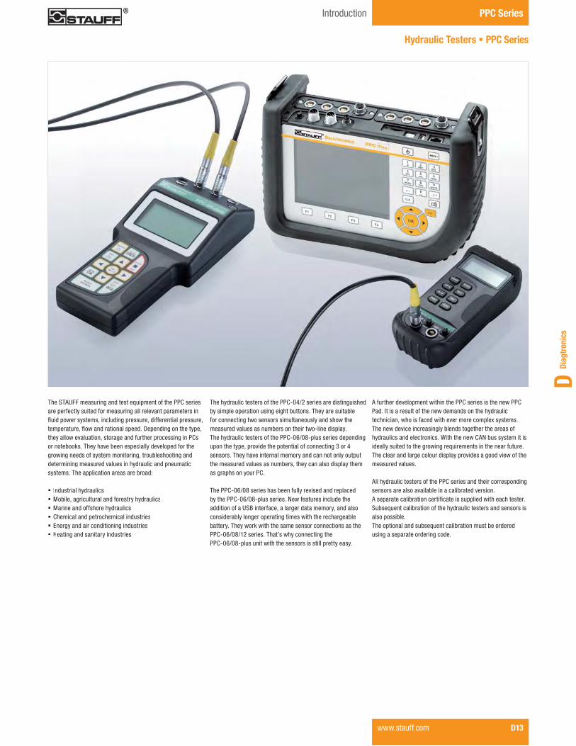
The STAUFF measuring and test equipment of the PPC series are perfectly suited for measuring all relevant parameters in ���������� ���������������������������������������������������������������������������������������� ��they allow evaluation, storage and further processing in PCs or notebooks. They have been especially developed for the growing needs of system monitoring, troubleshooting anddetermining measured values in hydraulic and pneumatic systems. The application areas are broad:
� Industrial hydraulics� Mobile, agricultural and forestry hydraulics� Marine and offshore hydraulics� Chemical and petrochemical industries� Energy and air conditioning industries� Heating and sanitary industries
Hydraulic Testers � PPC Series
The hydraulic testers of the PPC-04/2 series are distinguished by simple operation using eight buttons. They are suitable for connecting two sensors simultaneously and show the measured values as numbers on their two-line display. The hydraulic testers of the PPC-06/08-plus series depending upon the type, provide the potential of connecting 3 or 4 sensors. They have internal memory and can not only output the measured values as numbers, they can also display them as graphs on your PC.
The PPC-06/08 series has been fully revised and replaced by the PPC-06/08-plus series. New features include the addition of a USB interface, a larger data memory, and also considerably longer operating times with the rechargeable battery. They work with the same sensor connections as the PPC-06/08/12 series. That’s why connecting the PPC-06/08-plus unit with the sensors is still pretty easy.
A further development within the PPC series is the new PPC Pad. It is a result of the new demands on the hydraulic technician, who is faced with ever more complex systems. The new device increasingly blends together the areas of hydraulics and electronics. With the new CAN bus system it is ideally suited to the growing requirements in the near future. The clear and large colour display provides a good view of the measured values.
All hydraulic testers of the PPC series and their corresponding sensors are also available in a calibrated version. �������������������������������������������������������Subsequent calibration of the hydraulic testers and sensors is also possible. The optional and subsequent calibration must be ordered using a separate ordering code.

Rechargeable Battery – �� �� �� �� ��
Battery Operation �� – – – – –
Number of Sensor Inputs 2 2 2 3 4 max. 6+CAN
PC Interface – – RS-232 USB USB USB / Ethernet
Online Function – – �� �� �� ��
Internal Memory – – – �� �� ��
Programming of Automatic Measuring Tasks – – – �� �� ��
Internal Trigger Function – – – �� �� ��
Data Display �� �� �� �� �� ��
Graphic Display – – – �� �� ��
Display Lightning – – – �� �� ��
Curve Printout on Display – – – – – ��
PC Software Kit – – � �� �� ��
Pressure Measurement �� �� �� �� �� ��
Temperature Measurement �� �� �� �� �� ��
Flow Measurement �� �� �� �� �� ��
Rotational Speed Measurement �� �� �� �� �� ��
Frequency Measurement – – – �� �� ��
External Trigger Function – – – �� �� ��
Third-Party Sensors – – – �� �� ��
Current / Voltage Adaptor – – – �� �� ��
STAUFF-CAN-Sensor – – – – – ��
Options PPC-04-B/2 PPC-04-A/2 PPC-04-AP/2 PPC-06-plus PPC-08-plus PPC-Pad
��= Optional, �� = Standard, – = not available
Hydraulic Testers � PPC Series
PPC Series PPC Series - Product Overview
D14 www.stauff.com

Diag
tron
ics
D
www.stauff.com D15
PPC SeriesProduct Information / Order Codes
TS
TSH
ZERO
IN1=IN2
REC
OK
STOP
ESC
DISP
LINE
RESET
MIN/MAX
MEM
SET
�
��
�
� �
�
�
� �
�
� PPC-04/2 hydraulic tester A maximium of 2 connecting cables for sensors can be connected at the same time. � PPC-06-plus or PPC-08-plus hydraulic tester A maximium of 3 or 4 connecting cables for sensors can be connected at the same time. � PPC-04/12-110/230V AC power supply unit (not for PPC-04-B/2) � PC connecting cable as a component of the PC-SET-04-SW-CAB � PPC-04/12-RS232-to-USB-CAB PC adaptor cable
��������������� ����
All units are available as calibrated version.
Hydraulic Testers � PPC Series
� PPC connecting cable as a component of the PC-SET-06/08-plus-SW-CAB (USB) PC set� PPC-04/12-CAB3 (3 m / 9.84 ft) 5-pin connecting cable, optionally with PPC-04/12-CAB5-EXT (5 m / 16.40 ft) extension cable PPC-04/12-PT-/2 pressure sensor PPC-04/12-TS screw-in temperature sensor with M10 x 1 connection, optionally with SGV-16S-G-C6F straight threaded pipe joint� PPC-04/12-TSH manual temperature sensor
� PPC-04/12-SDS-CAB rotational speed sensor with integrated connecting cable, optionally with PPC-04/12-SKA-Contact contact adaptor or PPC-04/12-SKA-Focus focusing adaptor ���!"#$%&!'*������������������������������� converter� ���!"#$%&!'+7����������������������������� converter, for connecting pressure and temperature sensor

PPC Series Product Information / Order Codes
D16 www.stauff.com
Hydraulic Tester � Type PPC-04/2
Product Description
The PPC-04/2 Hydraulic Testers were designed for initial �����!������;�������������������<������������systems. Hydraulic systems are becoming more and moreaccurate and thus require quick, simple checking of the hydraulic key data.
� Two-line displayTT� 5-pin sensor input� “ZERO” function
The PPC-04/2 can be operated simply, using eight buttons. Just like all testers of the PPC series, it is superbly suited for measuring operating pressure, peak pressure, differential���������������������������������������������The tester has two separate test inputs that automaticallydetect the connected sensors. The new two-line display now allows simultaneous display of both sensor inputs.The measuring unit can be selected during power-on at the touch of a button.The ruggedness of the tester continues in the rubber protective coating that protects the actual tester against impacts. Voltage is supplied either by a commercially available 9 V battery (PPC-04-B/2) or from an integrated rechargeable battery (PPC-04-A/2 and PPC-04-AP/2).
Measurements taken over a lengthy period of time are possible, using a power supply (not for the PPC-04-B/2) which charges the rechargeable battery at the same time.The data printout is used for the documentation requirement within the scope of ISO 9001 and is compliant with CE.
The PPC-04/2 can be connected to a PC via an RS-232interface through a data output (only for the PPC-04-AP/2). Connection to a USB port is possible using an optional adaptor. The PPC-04/2 software that can be ordered separately is compatible with popular PC operating systems such as Windows 95®, Windows 98®, Windows 2000®, Windows NT®, Windows XP®, Windows Vista® and Windows 7®.
It is also possible to connect the pressure sensors underload, with the equipment switched on. The temperature and ;�����������������������������������������������?��rotational speed sensor is a non-contacting sensor and uses an optical mark on the rotating parts. Measuring the differ-ential pressure requires two pressure sensors with identicalmeasuring ranges.The units are also available as a complete set. Please seepage D26.
Note: The hydraulic tester does not have an internal memoryfor measured values (except for the temporary MIN-/MAX memory)!
Technical Data
Materials� Housing made of ABS in a rubber protective
case with carrying strap and stand
Dimensions and Weight� L/W/H: 145 x 70 x 40 mm /
5.71 x 2.76 x 1.57 in� Weight: 330 g / .73 lbs
Measurements / Display � Pressure: in bar and PSI� Temperature: in °C and °F� *�������Q� ����$��������Y'�[�7� Rotational speed: in RPM� Two-line LCD display (4-digit)TT
Numeral height: 8 mm / .32 in � Data output for connection to notebook or PC
(PPC-04-AP/2 only)
Power Supply� Power supply unit 110/230 V AC (50/60 Hz)
(PPC-04-A/2 and PPC-04-AP/2)� Internal rechargeable battery 9 V / 110 mAh� Operating time with the rechargeable battery: approx. 5 hours
Order Codes
� Series and Type PPC-04
� Version With battery B/2 With rechargeable battery A/2 With rechargeably battery and data output AP/2
- B/2 PPC-O4
Software
An optional PC set is available for the PPC-04-AP/2, for connecting it to a PC or a notebook. This set contains both aPC adaptor (RS-232 connection, length: 2 m / 6.56 ft) and the corresponding PC software. The measured values can then easily be processed as a data series or a chart using MicrosoftExcel®.
Two separate test inputs
* FS = Full Scale
Sensor Inputs (5-Pin)� Automatic sensor detection� ]�����������Q "�����^�*����_`�{�#|" <}~� Sampling rate: 2 ms� Accuracy: < ±0,25% FS*
Data Output� RS-232 interface� Optionally with RS-232 adaptor to USB
Permissible Temperatures� Ambient: 0°C ... +50 °C / +32°F ... +122 °F� Storage: -20°C ... +60 °C / -4°F ... +140 °F
� Relative humidity: < 85 %� ���������
Protection Rating� IP 54 protection rating: Dust protected and protected
against splashing water

Diag
tron
ics
D
www.stauff.com D17
PPC SeriesProduct Information / Order Codes
Hydraulic Tester � Type PPC-06/08-plus
Product Description
The PPC-06/08-plus Hydraulic Testers have been especially developed for the growing demands of system monitoring and troubleshooting in hydraulic and pneumatic systems. The PPC-06/08 series has been fully revised and replaced by the PPC-06/08-plus series. New features include theaddition of a USB interface, a larger data memory, and alsoconsiderably longer operating times with the rechargeablebattery. They work with the same sensor connections as theold PPC-06/08/12 series.
� Automatic sensor detection � Larger data memory � Possible to record MIN-/MAX values over long periods � Internal trigger function � External trigger function � Online data transmission � Display lighting � Programming by PC and notebook � USB interface
The ergonomically designed housing and the LCD display, which sets automatically to the appropriate line size, now�������������������;�����������������;���������conditions.The individual PPC-06-plus and PPC-08-plus testers differ in the number of sensor inputs (3-channel or 4-channel technology).The PPC-06-plus and PPC-08-plus can measure, store andprocess all relevant hydraulic parameters such as pressure,���������������������������������������������������The comprehensive programmer options, and the internalmemory capacity in particular, allow for diverse measurement and evaluation methods such as long-term measurements,trigger functions or measuring data from third-party sensors.
The PPC-06/08-plus devices can store up to 1000000 measuring value points and 240000 curve memory points. The stored values can be transferred using the built-in USBinterface to a PC or to a notebook. The included PPC softwareis compatible with popular PC operating systems (Windows95®, Windows 98®, Windows 2000®, Windows NT®, Win-dows XP®, Windows Vista® and Windows 7®) and permits various evaluation methods.
The automatic sensor recognition feature makes the PPC-06-plus and PPC-08-plus hydraulic testers easy to operate, and�������������������;������ �����������������������requirements without a great programming effort. Bothhydraulic testers allow the data from third-party sensors to bemeasured and processed.The units are also available as a complete set. Please see page D26.
PPC-08-plus with 4 sensor inputs
Technical Data
Material� �����������������������!�����������
Dimensions and Weight� L/W/H: 235 x 106 x 53 mm /
9.25 x 4.17 x 2.09 in� Weight: 530 g / 1.17 lbs
Measurements / Display � Pressure: in bar and PSI� Temperature: in °C and °F� *�������Q ����$��������Y'�[�7� Rotational speed: in RPM� Digital LCD display: 128 x 64 Pixel
Visible area: 72 x 40 mm / 2.84 x 1.58 in� Automatic numeral height adjustment
Numeral height: 6 mm / .24 in with eight-line display� Data output for connection to notebook or PC� 12-key membrane keyboard� Electromagnetic compatibility (EMC):
Emitted interference: DIN EN 50081, Part 1 Interference immunity: DIN EN 50082, Part 2
� Auto Power Off (after 20 minutes)� Battery charge display
Measured Data Memory� Variable storage interval (1 ms ... 10 s) or variable storage
time (2 s ... 100 h)� Manual and automatic triggering
Order Codes
� Series and Type PPC
� Version With 3 sensor inputs 06-plus With 4 sensor inputs 08-plus
- 06-plus PPC
Software
A PC set, consisting of a USB connecting lead, Length 1,5 m/ 4.9 ft and the corresponding PC software, is included asstandard with every PPC-06-plus and PPC-08-plus.
The measured data and curves can easily be processedusing Microsoft Excel® with the software.
Version No. Sensor Integrated Data Memory forInputs Measuring Value Points Storable Curves
06-plus 3 1000000Points
240000Points08-plus 4
Power Supply� Power supply unit: 110/230 V AC (50/60 Hz)� Rechargeable battery charging circuit� Internal nickel-metal hybrid rechargeable battery 7,2 V / 700 mAh� Operating time with the rechargeable battery: approx. 8 hours
Sensor Inputs (5-Pin)� Automatic sensor detection� ]�����������Q "�����^�*����_`�{�#|"�<}~� Frequency range: 0,5 Hz ... 30 kHz� Sampling rate: 1 ms� Accuracy: < ±0,25% FS*
Data Output � Integrated USB port (USB 2.0) � Online data transmission to a PC Speed individually eligible (5 ms ... 60 s)
Permissible Temperatures� Ambient: 0 °C ... +50 °C / +32 °F ... +122 °F� Storage: -25 °C ... +60 °C / -13 °F ... +140 °F� Temperature error: < 0,02 % / °C
� Relative humidity: < 80 %� ���������� IP 54 protection rating: Dust protected and protected
against splashing water
* FS = Full Scale

PPC Series Product Information / Order Codes
D18 www.stauff.com
Product Description
The PPC-04/12-PT/2 Pressure Sensors can be used with all hydraulic testers of the PPC series, due to their 5-Pin connection. As an additional feature, the new generation of PPC-04/12-�?�'������_�������������$&�����������~�������������measure and display temperature (only with the PPC-06/08-plus and PPC-Pad hydraulic testers). ?��'?�Y++��������'���������������������������solution for the PPC series because of their sturdy StainlessSteel design, the quick response times (< 1 ms) and the highaccuracy (±0,25 % FS* typ.) with automatic sensor detection.
Note: A PPC-04/12-CAB3 (3 m / 9.84 ft) cable is neededto connect the PPC-04/12-PT/2 Pressure Sensors to the current PPC Hydraulic Testers. A PPC-04/12-CAB5-EXT(5 m / 16.40 ft) extension cable is also available as an accessory!
Note: The temperature measurement data from the PPC-04/12-PT/2 Sensors can only be displayed using the PPC-06/08-plus and PPC-Pad hydraulic testers.The PPC-units allow the evaluation and further processing of the measured values obtained.
Pressure Sensor � Type PPC-04/12-PT/2
Technical Data
� Sturdy Stainless Steel housing (1.4301)� FPM (Viton®) gasket� Weight: 200 g / .44 lbs� Suitable for gases and liquids (in the case of aggressive media,
only after consultation)� 5-Pin connection� Pressure connection G1/2 (without adaptor)
Ambient Conditions� Media temperature: max. +105 °C / +221 °F� Ambient temperature: -25°C ... +80°C / -13°F ... +176 °F� Storage temperature: -20°C ... +80°C / -4°F ... +176°F� Compensated range: -0°C ... +85°C / +32°F ... +285°F� Load cycles (106): 100
Version Pressure Range and AccuraciesgSensorPPC-04/12-PT-
Pressure MeasuringRange (bar/r PSI)
Type of Measurement
Maximum Pressure(bar/r PSI)
Burst Pressure (bar/r PSI)
Accuracy (±% FS*) typ.
Accuracy (±% FS*) max.
Temperature Measuring Range (°C/°F)
Accuracy Temp.Sensor(±% FS*)
015/2-1 ... 15**
Relative pressure30 150
0,25 0,5-25 ... 105
1,5-14.5 ... 217 435 2175 -13 ... 221
060/20 ... 60
Absolute pressure120 500
0,25 0,5-25 ... 105
1,50 ... 870 1740 7251 -13 ... 221
150/20 ... 150
Absolute pressure300 900
0,25 0,5-25 ... 105
1,50 ... 2175 4351 13053 -13 ... 221
400/20 ... 400
Absolute pressure800 1200
0,25 0,5-25 ... 105
1,50 ... 5801 11603 17404 -13 ... 221
600/20 ... 600
Absolute pressure1200 1800
0,25 0,5-25 ... 105
1,50 ... 8702 17404 26106 -13 ... 221
601/20 ... 600 ***
Absolute pressure1200 2500
0,25 0,5-25 ... 105
1,50 ... 8702 17404 36259 -13 ... 221
Electrical Data and Output� Input voltage: 7 ... 12 V DC� Current consumption: 5 mA� Output signal: 0 ... 3 V DC� Response time: 1 ms� Long-term stability: < 0,2 % FS* /a� Vibration loading: IEC 68-2-6/10 ... 500 Hz� Shock loading: IEC 68-2-29
Connection Adaptors for PPC Pressure Sensors
In addition to the PPC-04/12-PT/2 Pressure Sensors, different adaptors and adaptor sets are available that not only connect to the STAUFF Test 20 system (SDA20-G1/2-C6F) but also to the test points of the STAUFF Test 15/12/10 series (SAD20/15-P-C6F, SAD20/12-P-C6F, SAD20/10-P-C6F). For further information please see the STAUFF Test section.
- 015/2 - 015/2 015/2 CALPPC-04/12-PT
Order Codes
� Series and Type Pressure Sensor PPC-04/12-PT
� Version Please see table below
� Calibration ���������������������������� (none) ������������������������� CAL
G 1/2
M 16
53,6
,5
39
M 16
M 16
39
S 12,65 x 1,5
M 16
37
SDA20-G1/2-C6F SAD20/15-P-C6F
SAD20/12-P-C6F SAD20/10-P-C6F
Pressure Range and Accuracies
26,9(1.06)Ø12(.04)
G1/2
Ø26(1.02)
68,6
(2.7
0)
10,5
(.41)
14 (.55)
16,5
(.65)
(2.1
1)(1
.53)
(1.4
5)(1
.53)
pPPC-04/12-PT/2 with adaptor and cable
* FS = Full Scale** 0 ... 15 bar (0 ... 217 PSI) when used with the PPC-04/2 series
*** Pressure peaks up to 1000 bar / 14503 PSIe s o a d a gs d e s o s ( )Dimensional drawings: All dimensions in mm (in).

Diag
tron
ics
D
PPC SeriesProduct Information / Order Codes
www.stauff.com D19
Product Description
The PPC-04/12-TS Screw-in Temperature Sensor measures current temperatures directly in the pipeline and is compatible with the PPC-04/12-SFM Flow Turbine (see page D21) and the SGV-16S-G-C6F straight threaded joint.
The new PPC-04/12-TSH Rod-type Temperature Sensor is especially designed to determine the media temperatures in tanks and containers.
Both sensors can measure media temperatures without problems up to +125 °C / +257 °F.
Note: A PPC-04/12-CAB3 (3 m / 9.84 ft) cable is needed to connect the PPC-04/12-TS or the PPC-04/12-TSH Tempera-ture Sensors to the current PPC hydraulic testers.A PPC-04/12-CAB5-EXT (5 m / 16.40 ft) extension cable isalso available as an option!
PPC-04/12-TSPPC-04/12-TSH
Technical Data
� Housing (TS): Steel (C15K)� Gaskets (TS): FPM (Viton®)� Rod (TSH): Stainless Steel 1.4304� Handle (TSH): Delrin� Weight (TS): 100 g / .22 lbs� Weight (TSH): 120 g / .26 lbs� Measurement medium: liquids (consult STAUFF for
use with aggressive media)� 5-Pin connection� Connection:
a) STAUFF Test connection SGV-16S-G-C6F in the �������_?'��������~�~�'��!���������7%"���%�_?'��������~c) Screw-in thread M10 (TSH)
Ambient Conditions� Media temperature: max. +125 °C / +257 °F� Ambient temperature: -25°C ... +70°C / -13°F ... +158°F� Storage temperature: -25°C ... +80°C / -13°F ... +176°F
Measuring Range � Measuring range: -25 °C ... +125 °C / -13 °F ... +257 °F � Operating pressure (TS): 630 bar / 9137 PSI � Maximum pressure (TS): 800 bar / 11603 PSI � Burst pressure (TS): 1200 bar / 17404 PSI � Accuracy: ±1,5 °C
Electrical Data and Output � Output signal: 0 ...3 V DC � Input signal: 7 ...12 V DC � Response time T0.9 (TS): approx. 13,5 s � Response time T0.9 (TSH):approx. 9,1 s � IP 54 protection rating: Dust protected and protected against splashing water (TS)
- TS - TS TS PPC-04/12 CAL
Order Codes
� Series and Type PPC-04/12
� Version Screw-in TS Rod-type TSH
� Calibration ���������������������������� (none) ������������������������� CAL
Ø16,5(.65)Ø14(.55)
SW 17
Ø7(.28)
Ø10(.39)
50(1
.97)
8(.3
1)
17,5
2(.6
9)7
(.28)
Ø23(.91)
M10
Ø4(.16)
275
(10.
83) 36
0(1
4.17
)
Hex .67
Temperature Sensor � Type PPC-04/12-TS /-TSH
Screw-in Hole PPC-04/12-TS
6060°
Ø ,5,,,Ø11,5 +0,05,,++0,05
(.45)
(.35)
9m
in. 9
17 (.65)
R z16
0,5,, 0,5+
0,1
(.02)
(.09)
2,5,,, 2,5+
0,2
0M10x1
SGV-16S-C6F with PPC-04/12-TS
Temperature sensors TS and TSH with cables
* FS = Full Scalee s o a d a gs d e s o s ( )Dimensional drawings: All dimensions in mm (in).
For further information on available connection adaptors please see the “STAUFF Test” chapter.For information on SGS-16-G-C6F please see the STAUFF Test section.

PPC Series Product Information / Order Codes
D20 www.stauff.com
Rotational Speed Sensor � Type PPC-04/12-SDS-CAB
Product Description
The PPC-04/12-SDS-CAB Rotational Speed Sensor allows non-contact speed measurement of rotating components. The sensor is based on an opto-electrical measurement principle that determines the rotational speed with high ������� ������������������������������������
The contact rotational speed measurement is obtained byusing a contact adaptor that is mounted to the sensor, and which makes contact with the rotating component during measurement.This also produces high-accuracy measurement results.In the case of especially small areas, using the focusing adaptor facilitates measurement.
Technical Data
� Material: ABS� Weight: 230 g / .51 lbs� 5-Pin connection� Both contacting and non-contacting measurement
possible� Type of measurement:TT Optical, red LED
Ambient Conditions� Ambient temperature: 0°C ... +70°C / +32°F ... +158 °F
Measuring Range � Measuring range: 20 ... 10000 RPM
� Measuring distance: 25 ... 500 mm (1 ... 20 in) � Measuring angle: ±45 °C � Accuracy: < ±0,5 % FS* � Resolution: ±5 RPM
Electrical Data and Output � Output signal: 0 ... 3 V DC � Input signal: 7 ...12 V DC
Note: We recommend not extending the 2 m / 6.56 ft permanent cable connection provided on the sensor!
- CALPPC-04/12-SDS-CAB
Order Codes
� Series and Type Rotational Speed Sensor PPC-04/12-SDS-CAB
� Calibration ���������������������������� (none) ������������������������� CAL
Application Examples
Fig. 1 -Contacting rotational speed measurement with the contact adaptor.
Fig. 2 - End face rotational speed measurement with the contact adaptor
Fig. 3 - Rotating shaft / non-contacting rotational speed measurement using the focusing adaptor and marking strip
130(5,11)
Ø 34(1,33)
70(2
,75)
Ø 32,5(1,28)
Perimeter: 100 (3,93)
PPC-04/12-SKA-Contact Adaptor
Ø 32,5(1,28)
26(1
,02)
PPC-04/12-SFA-Focus AdaptorPPC-04/12-SDS-CAB
PPC-04/12-SFA-focus adaptor
Focus Adaptor
� Series and Type Focus Adaptor PPC-04/12-SFA-focus adaptor
PPC-04/12-SKA-contact adaptor
Contact Adaptor
� Series and Type Contact Adaptor PPC-04/12-SKA-contact adaptor
Order Codes
* FS = Full ScaleDimensional drawings: All dimensions in mm (in).

Diag
tron
ics
D
PPC SeriesProduct Information / Order Codes
www.stauff.com D21
Flow Turbine � Type PPC-04/12-SFM
Product Description
The PPC-04/12-SFM Flow Turbine is permanently installed in ����������?�����������������������������������������?��frequencies generated are processed by digital electronics (a signal converter). Flow effects causing interference are compensated in this process. The signal converter is now directly integrated into the PPC-04/12-SFM Flow Turbine. This allows even simpler operation and supports permanent coupling of the turbine and signal converter components that are matched to one another.
The new turbine also improves the response times (from previously 400 ms to 50 ms) and increases the measuring accuracy.
?�����!"#$%&!'+7�+���?����������;�����������;�;�����������;����������������A pressure sensor (see page D18) can be connected in parallel����������������� �� ��������������������������In addition, the oil temperature can also be measured using the temperature sensor connection (see page D19).
Order Codes Technical Data
Materials � Housing: Aluminium (black anodised) � Gaskets: FPM (Viton®)
� 5-Pin connection � Pressure measurement connection: SMK20 (M16 x 2)
� Temperature measurement connection: M10 x 1 (standard screw plug)
Ambient Conditions � Media temperature: -20 °C ... +90 °C / -4 °F ... +194 °F � Ambient temperature: -10 °C ... +50 °C / +14 °F ... +122 °F � Storage temperature: -20 °C ... +80 °C / -4 °F ... +176 °F � Permissible particle size: <10 Micron for SFM-015, <25 Micron for others Note: To ensure the permissible particle size the use of a � � ��������������������+���?������������������
� Viscosity range: 10 ... 100 cSt
Electrical Data and Output � Response time: 50 ms
Process Connection� Please see table below
]���������������!"#$%&!'+7�+���7�����������������������������������?������������������������������������������_�;�������������������~����� ���� ������������������������������������������������������������A double-headed arrow is shown on the nameplate of the PPC-04/12-SFM. The thicker end of the double-headed arrow ����������������������������������
Note:A PPC-04/12-CAB3 (3 m / 9.84 ft) cable is needed toconnect the PPC-04/12-SFM Flow Meter to the current PPChydraulic testers.A PPC-04/12-CAB5-EXT (5 m / 16.40 ft) extension cable isalso available as an option!
Dimensions and Measuring Range
Version Measuring Range Dimension (mm/in)Flow TurbinePPC-04/12-
Measuring Range (l/min/US GPM)
Max. Flow(l/min/US GPM)
Operarting Pressure (bar/r PSI// )
Max. Pressure (bar/r PSI// )
Accuracy (at 21 cSt)
Max. PressureDrop (at FS*) (bar/r PSI// )
G **(BSP)
G (UNF)
B D L H Weight (g/lbs)
SFM-0151 ... 15 16,5 350 420
±1 (% FS*)1,5
G1/2 3/4–1637 80 136 37 650
.27 ... 3.90 4.4 5076 6091 21.8 1.46 3.15 5.35 1.46 1.4
SFM-0603 ... 60 66 350 420 ±1 (% of the
displayed value)1,5
G3/4 1-1/16–1662 80 190 50 750
.79 ... 15.90 17.4 5076 6091 21.8 2.44 3.15 7.48 1.97 1.6
SFM-1505 ... 150 165 350 420 ±1 (% of the
displayed value)1,5
G3/4 1-1/16–1662 80 190 50 750
1.32 ... 39.60 43.6 5076 6091 21.8 2.44 3.15 7.48 1.97 1.6
SFM-3008 ... 300 330 350 420 ±1 (% of the
displayed value)4
G1 1-5/16–1662 84 190 50 1200
2.11 ... 79.00 87.2 5076 6091 58 2.44 3.31 7.48 1.97 2.6
SFM-60015 ... 600 660 290 348 ±1 (% of the
displayed value)5
G1-1/4 1-5/8–1262 75 212 75 1800
3.96 ... 158.00 174.4 4206 5047 72.5 2.44 2.95 8.35 2.95 4
SFM-75025 ... 750 825 400 480 ±1 (% of the
displayed value)5
- 1-7/8–12100 79 212 75 2100
5.28 ... 198.13 217.4 5801 6961 72.5 3.94 3.11 8.35 2.95 4.6
`����������������������
L
H GGD
B
� Series and Type Flow Turbine PPC-04/12
� Version 1 ... 15 l/min / .27 ... 3.90 US GPM SFM-015 3 ... 60 l/min / .79 ... 15.90 US GPM SFM-060 5 ... 150 l/min / 1.32 ... 39.60 US GPM SFM-150 8 ... 300 l/min / 2.11 ... 79.00 US GPM SFM-300 15 ... 600 l/min / 3.96 ... 158.00 US GPM SFM-600
� Calibration ���������������������������� (none) ������������������������� CAL
� Port Connection BSP (none) UNF UN
Signal converter
Temperature sensorconnection (M10 x 1)
Test point,pressure sensor connection (M16 x 2)
UN- SFM-015 - CAL - SFM-015 SFM-015 PPC-04/12 CAL CAL

PPC Series Product Information / Order Codes
D22 www.stauff.com
Product Description
The PPC-04/12-SVC Gear Flow Meter is permanently installed in the pipeline of the hydraulic system. Highly accurate, low-���������������������������������������������because of a very accurate gear pair. A wide range of viscosities can be handled and even values �����������;������_���<�������'< ������������������lubricants, isocyanates, greases, etc.) can be measured by using different gaskets.
The PPC-04/12-SVC Gear Flow Meter is available in four versions (up to 300 l/min, 79 US GPM) and is resistant to pressures up to 400 bar / 5801 PSI or 315 bar / 4568 PSI.
The PPC-04/12-SVC Gear Flow Meter always includes a connection plate and a signal converter (both already assembled).
?������������������;�������������������������;������optionally apply only if the PPC-04/12-SVC Flow Meter is ���������������������������������������_�����������~����������������<������������;���������������
Gear Flow Meter � Type PPC-04/12-SVC
Technical Data
Materials� Housing: GGG 40� Gaskets: FPM (Viton®)
� 5-Pin connection� Response time: 400 ms
Ambient Conditions and Measuring Range� Max. media temp.: +110 °C / +230 °F� Ambient temperature: +10°C ... +50°C / +50°F ... +122°F� Storage temperature: -20°C ... +80 °C / -4°F ... +176 °F� Permissible particle size: < 25 Micron� Viscosity range: see the charts
Process Connections� Please see table on page D23
Note:A PPC-04/12-CAB3 (3 m / 9.84 ft) cable is needed toconnect the ���!"#$%&!'*�������� to the current PPChydraulic testers. A PPC-04/12-CAB5-EXT (5 m / 16.40 ft) extension cable is also available as an option!
Order Codes
- CAL- PPC-04/12 SVC-015 SVC-015
Pressure Drop Curves / Viscosity Curves
16
14
12
10
8
6
4
2
0
600
300
100
34
3000 1000
0 2 4 6 8 10 12 14 16
PPC-04/12-SVC-150 P-Viscosity
100
34
5
3000 2000 1000 600
0 20 40 60 80 100 120 140 160
Q in l/min
���
����
PPC-04/12-SVC-060 P-Viscosity
100
34
10
3000 1000 600 300
0 10 20 30 40 50 60 70 80
PPC-04/12-SVC-300 P-Viscosity
100
34
10
3000 1000 600 300
0 50 100 150 200 250 300
� Series and Type Gear Flow Meter PPC-04/12
� Version 0,2 ... 15 l/min / .05 ... 3.90 US GPM SVC-015 0,4 ... 60 l/min / .10 ... 15.90 US GPM SVC-060 0,6 ... 150 l/min / .20 ... 39.60 US GPM SVC-150 1 ... 300 l/min / .30 ... 79 US GPM SVC-300
� Calibration ���������������������������� (none) ������������������������� CAL
���
����
�
232
203
174
145
116
87
58
29
0
Q in US GPM0 .5 1.0 1.6 2.1 2.6 3.2 3.7 61.5
cSt
16
14
12
10
8
6
4
2
0
���
����
���
����
�
232
203
174
145
116
87
58
29
0Q in l/minQ in US GPM0 5.5 10.5 16 21 26 32 37 615
cSt
16
14
12
10
8
6
4
2
0
���
����
���
����
�
232
203
174
145
116
87
58
29
0Q in l/minQ in US GPM0 3 5.5 8 10.5 13 16 18 21
cSt
16
14
12
10
8
6
4
2
0
���
����
���
����
�
232
203
174
145
116
87
58
29
0Q in l/minQ in US GPM0 13 26 39 52 65 78
PPC-04/12-SVC-015 P-Viscosity

Diag
tron
ics
D
PPC SeriesProduct Information / Order Codes
www.stauff.com D23
Gear Flow Meter � Type PPC-04/12-SVC
D
M
Ø N O-ring
41 J(1,61)
M12
x1
FC
GP
64(2
,52)
58(2,28)
Tightening torque
K
A
L
ØH
C
JR
ØG
AEK
Pf
Ø N
Øe
Ød
c
M
L
F
B
Flowmeter Connection Plate
Version Measuring RangesFlow MeterPPC-04/12-
Measuring Range(l/min/US GPM)
Maximum Flow(l/min/US GPM)
Operating Pressure(bar/r PSI)
Maximum Pressure(bar/r PSI)
Accuracy(at 21 cSt)
Maximum Pressure Drop (at FS*) (bar/r PSI)
Total Weight(kg/lbs)
SVC-0150,2 ... 15 16,5 400 480
±0,5 (% FS*) see the chart3,8
.05 ... 3.90 4.40 5800 7300 8
SVC-0600,4 ... 60 66 400 480
±0,5 (% FS*) see the chart8,1
.10 ... 15.90 17.40 5800 7300 17.9
SVC-1500,6 ... 150 165 315 375
±0,5 (% FS*) see the chart23
.20 ... 39.60 43.60 4570 5440 50.7
SVC-3001 ... 300 330 315 375
±0,5 (% FS*) see the chart27
.30 ... 79 87.20 4570 5440 59.5
Measuring Ranges
Version Dimensions (mm/in)Flow MeterPPC-04/12-
A C D F G J K L M N P Torque[Nm]
Weight(kg/lbs)
SVC-01585 13 60 57 94
-70 40 20 9
M6 142
3.35 .51 2.36 2.24 3.70 2.76 1.57 .79 .35 4.4
SVC-060120 13 95 72 109 10,5 84 72 35 16
M8 355,2
4.72 .51 3.74 2.83 4.29 .41 3.31 2.83 1.38 .63 11.4
SVC-150170 18 120 89 140 46,5 46 95 50 25
M12 1209
6.69 .71 4.72 3.50 5.51 1.83 1.81 3.74 1.97 .98 19.8
SVC-300170 22 120 105 142 40 46 95 50 25
M12 12013
6.69 .87 4.72 4.13 5.59 1.57 1.81 3.74 1.97 .98 28.7
Flow Meter Dimensions
Version Dimensions (mm/in)Flow MeterPPC-04/12-
A B C E F G H J K L M N P R c d e f Weight(kg/lbs)
SVC-01585 90 35 65 76 7 11 7 70 40 20 6,5 M6 x 14 17 0,7 25
G3/8 BSP13 1,8
3.35 3.54 1.38 2.56 2.99 .28 .43 .28 2.76 1.58 .79 .26 M6 x .55 .67 .03 .98 .51 2.7
SVC-060100 120 37 80 106 7 11 7 84 72 35 12 M8 x 18 17,5 0,7 29
G1/2 BSP15 2,9
3.94 4.72 1.46 3.15 4.17 .28 .43 .28 3.31 2.83 1.38 .47 M8 x .71 .69 .03 1.14 .59 5.4
SVC-150160 165 80 140 145 9 15 9 46 95 50 25 M12 x 28 28,5 1 42
G1 BSP19 14
6.30 6.50 3.15 5.51 5.71 .35 .59 .35 1.81 3.74 1.97 .98 M12 x 1.10 1.12 .04 1.65 .75 37.5
SVC-300160 165 80 140 145 9 15 9 46 95 50 25 M12 x 28 28,5 1 42
G1 BSP19 14
6.30 6.50 3.15 5.51 5.71 .35 .59 .35 1.81 3.74 1.97 .98 M12 x 1.10 1.12 .04 1.65 .75 37.5
Connection Plate Dimensions
*FS = Full ScaleDimensional drawings: All dimensions in mm (in).

PPC Series Product Information / Order Codes
D24 www.stauff.com
Miscellaneous Measurements (only for PPC-06/08-plus and PPC Pad)
Characteristics
In addition to pressure, temperature, rotational speed and ��������������������!"�$"�!������ ��������?�����can measure and evaluate different signals from other or third-party sensors. The following connecting adaptors are available for these tasks:
� Current /Voltage Adaptor: PPC-06/12-A/V-A adaptor � External Trigger Adaptor: PPC-06/12-TR-A adaptor
ATTENTION! None of the two adaptors is suitable for use with the PPC-04/2.
Current / Voltage Adaptor
Measuring electrical signals or signals from a third-party sensor (e.g. 4 ... 20 mA, 0 ... 10 V, ...) with the PPC-06/12-A/V-A adaptor.
The PPC-06/12-A/V-A Current / Voltage Adaptor is used, for example, for measuring current at proportional valves or for determining the switching states of motors or pumps and to evaluate and process measurements from third-party sensors. Typical applications are the generation and measurement of a ����!����������������������!��������������������;���The following input signals can be processed by this adaptor:
� Electric currents up to 4 A DC � Electric voltages up to 48 V DC
The measured data are transmitted directly to the PPC-06/08-plus or PPC Pad hydraulic tester by a permanent cable connection.
PPC-06/12-A/V-A adaptor
Order Code
� Series and Type Current / Voltage Adaptor PPC-06/12-A/V-A adaptor
ZERO
IN1=IN2
REC
OK
STOP
ESC
DISP
LINE
RESET
MIN/MAX
MEM
SET
ZERO
IN1=IN2
REC
OK
STOP
ESC
DISP
LINE
RESET
MIN/MAX
MEM
SET

Diag
tron
ics
D
PPC SeriesProduct Information / Order Codes
www.stauff.com D25
Cables / Adaptors / Accessories
Characteristics
A number of cables, adaptors and accessories are also available. With these items, you may customize your hydraulic tester to your needs or ensure continued use of old sensors or measuringequipment. The following items are available for this purpose:
PPC-04/12-U5P-S4P Adaptor
It is no longer possible to use the old 4-pin measuring sensors when converting the PPC-04 series (sensors and hydraulic testers) to the current version using 5-pin connections without suitable adaptors. The simple and easy solution to this is the PPC-04/12-U5P-S4P adaptor. The adaptor has a 5-pin connection (connecting to the current PPC-04/2, PPC-06/08-plus hydraulic tester or PPC Pad) at one end and a 4-Pin push/pull connector (for connecting an older sensor) at the other end.
Order Code
� Series and Type Adapting older
Sensors to current PPC-04/12-U5P-S4P adaptorHydraulic Testers
PPC-04/12-U5P-S4P adaptor
Order Code
� Series and Type Adapting current
Sensors to older PPC-04/12-CAB2-U4P-S5PMeasuring Equipment
PPC-04/12-CAB2-U4P-S5P
Order Code
� Series and TypePC Set PC-SET PPC-04-SW-CAB
PC-SET PPC-04-SW-CAB
Order Code
� Series and Type PC Set PPC-SET PPC-06/08-PLUS-SW-CAB
PC-SET PPC-06/08-plus-SW-CAB
Order Code
� Series and Type Adaptor Cable PPC-04/12-RS232-to-USB-CAB
PPC-04/12-RS232-to-USB-CAB
PPC-04/12-CAB3 and PPC-04/12-CAB5-EXT PPC-04/12-U5P-S4P adaptor PC connecting cable as a component
of the PC-SET-04-SW-CAB
PPC-04/12-CAB2-U4P-S5P cable PC connecting cable as a component
of the PC-SET-06/08-plus-SW-CAB
PPC-04/12-R232-to-USB-CAB
PC adaptor cable
PPC-04/12-CAB2-U4P-S5P Cable The PPC-04/12-CAB2-U4P-S5P cable is intended for using current sensors (5-pin connection) with older hydraulic testers of the PPC-04 series (without the “/2” in the name, with the 4-pin sensor input). This adaptor cable has a length of 2 m / 6.56 ft, a 4-Pin connection (for connecting to the old PPC-04 hydraulic tester) on one end and a 5-pin push/pull connector (for connecting to the current measuring sensor) on the other end.
PC-SET PPC-04-SW-CAB
It is possible to connect the PPC-04-AP/2 hydraulic tester to a PC or notebook. The set contains one PC cable with RS-232 connection (2 m / 6.56 ft) and the corresponding PC software.The PC-SET PPC-04-SW-CAB is only suitable for the PPC-04-AP/2 (to be ordered optionally) because the other two testers of the PPC-04/2 series do not have a data output.
PC-SET PPC-06/08-PLUS-SW-CAB
A PC set, consisting of a USB connecting lead, length 1,5 m / 4.92 ft and the corresponding PC software. Note: The appropriate PC set is automatically included when purchasing a PPC-06/08-plus or PPC-Pad hydraulic tester.
PPC-04/12-R232-to-USB-CAB Adaptor
A suitable PC cable (PPC-Set PPC-04-SW-CAB) is available forconnecting a hydraulilc tester of the PPC series to a PC. As standard, this cable is equipped with a connection for the RS-232 interface. For connection to a USB port, the PPC-04/12-RS232-to-USB-CAB adaptor is also available. The cable has a length of 1 m / 3,3 ft.
Order Codes
� Series and Type Standard Connecting
Cable for Measuring Sensor PPC-04/12-CAB3
Extension Cable PPC-04/12-CAB5-EXT
PPC-04/12-CAB3
PPC-04/12-CAB3 Cable and PPC-04/12-CAB5-EXT Cable
A PPC-04/12-CAB3 cable is required to connect the sensors to the current hydraulic testers of the PPC-04/2, PPC-06/08-plus series or PPC Pad. The cable comes with a 5-pin push/pull connection at each end and has a length of 3 m / 9.84 ft.
Note: This cable cannot be used with older hydraulic testers and/or sensors (with the 4-pin connection)!The PPC-04/12-CAB5-EXT cable has a length of 5 m / 16 ft.Note: Please keep in mind that it is generally recommended not to exceed a total cable length of 8 m / 26.25 ft!

PPC Series Product Information / Order Codes
D26 www.stauff.com
Hydraulic Tester � Type PPC Complete System
Product Description PPC complete systems are assembled in different versions according to customer wishes. The complete systems are supplied in a handy case with individually designed pockets/sections and have space for the components listed beside.
Components
Standard option PPC-04/2 complete system� 1x PPC-04/2 hydraulic tester� 1x Power supply unit � Up to 3 pressure sensors with installed adaptor for STAUFF Test 20 (M16 x 2)
� Up to 2 connecting cables (3 m / 9.84 ft) � 1x TS temperature sensor, with installed SGV-16S-G-C6F (optional)
� 3x SAD adaptors for the STAUFF Test 15/12/10 series (standard for all PPC complete systems)
� 1x Operating instructions (multilingual) on CD
Standard option PPC-06/08-plus complete system� 1x PPC-06-plus or PPC-08-plus hydraulic tester � 1x Power supply unit � Up to 3 pressure sensors with installed adaptor for STAUFF Test 20 (M16 x 2)
� Up to 3 connecting cables (3 m / 9.84 ft) � 1x TS temperature sensor, with installed SGV-16S-G-C6F (optional)
� 3x SAD adaptors for the STAUFF Test 15/12/10 series (standard for all PPC complete systems)
� 1x Printed user manual (German and English) � 1x User manual (multilingual) on CD � 1x PC software for the PPC-06/08-plus � 1x PC connecting cable
Note: Please consult STAUFF for calibrated version.
- 04-AP-SET - 2 - T - 015 / 060 / 04-AP-SET 04-AP-SET 2 2 PPC T T 015 015 060 060 000
Order Codes
� Series and Type STAUFF Hydraulic Tester PPC
� Version 2 Sensor inputs, without internal data
memory, battery-operated 04-B-SET
2 Sensor inputs, without internal datamemory, with rechargeable battery, 04-A-SETpower supply unit, without data output
2 Sensor inputs, without internal datamemory, with rechargeable battery, 04-AP-SETpower supply unit and data output
3 Sensor inputs, including PC softwareand PC connecting cable 06-SET
4 Sensor inputs, including PC softwareand PC connecting cable 08-SET
Complete System PPC-06/08-plusp y Complete System PPC-04/2
Pressure Ranges and Pressure Sensor
Pressure Range Pressure Sensor
000 When ordering a complete system with one or two pressure sensors, specify „000“ for the pressure range ofthe second and / or third sensors.
015
���������������������sensor
Pressure range second pressure sensor
Pressure range third pressure sensor
060150400600601e.g. 015 (15 bar PT) 060 (60 bar PT) 000 (0 bar PT)
Please keep in mind that two pressure sensors with identical measuring ranges are necessary for differential pressure measurements.
� Number of Pressure Sensors With one pressure sensor 1
With two pressure sensors 2With three pressure sensors 3
� Temperature Sensor Without TS temperature sensor with SGV (none) With TS temperature sensor with SGV T
� Pressure Range and Pressure Sensor First pressure sensor see table
� Pressure Range and Pressure Sensor Second pressure sensor see table
� Pressure Range and Pressure Sensor Third pressure sensor see table
Diag
tron
ics
D
PPC Series
www.stauff.com D27
Hydraulic Test Equipment
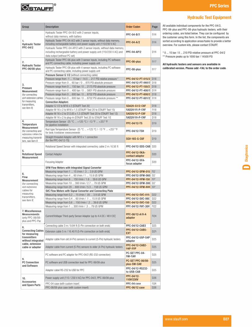
All available individual components for the PPC-04/2, PPC-06-plus and PPC-08-plus hydraulic testers, with their ����������������������������?� ������������������ �the customer using this form. In the list, the components aresorted according to application areas/tasks to provide a better overview. For custom kits, please contact STAUFF.
* 0 ... 15 bar / 0 ... 210 PSI relative pressure at PPC-04/2** Pressure peaks up to 1000 bar / 14500 PSI
All hydraulic testers and sensors are available in calibrated version. Please add -CAL to the order code.
Group Description Order Codes Page
1.Hydraulic TesterPPC-04/2
Hydraulic Tester PPC-04-B/2 with 2 sensor inputs, without data memory, with battery
PPC-04-B/2 D16
Hydraulic Tester PPC-04-A/2 with 2 sensor inputs, without data memory, including rechargeable battery and power supply unit (110/230 V AC)
PPC-04-A/2 D16
Hydraulic Tester PPC-04-AP/2 with 2 sensor inputs, without data memory, including rechargeable battery and power supply unit (110/230 V AC) anddata output (without PC set)
PPC-04-AP/2 D16
2.Hydraulic TesterPPC-06/08-plus
Hydraulic Tester PPC-06-plus with 3 sensor inputs, including PC softwareand PC connecting cable, including power supply unit PPC-06-plus D17
Hydraulic Tester PPC-08-plus with 4 sensor inputs, including PC software and PC connecting cable, including power supply unit
PPC-08-plus D17
3. Pressure Measurement(for connecting and extension cables for measuringtransmitters,see item 8)
Pressure Sensor G 1/2 (without connecting cable)Pressure range from -1 ... 15 bar / -14.5����������� ���������������� PPC-04/12-PT-015/2 D18��������������������������!�������"����� ��������������� PPC-04/12-PT-060/2 D18����������������������#����!����������#��� ��������������� PPC-04/12-PT-150/2 D18���������������������$�����!�������#"����� ��������������� PPC-04/12-PT-400/2 D18���������������������������!�������"������ ��������������� PPC-04/12-PT-600/2 D18���������������������������!�������"������ ������������������ PPC-04/12-PT-601/2 D18Connection AdaptorsAdaptor G 1/2 to M16 x 2 (STAUFF Test 20) SDA20-G1/2-C6F D18Adaptor M 16 x 2 to M16 x 1,5 (STAUFF Test 20 to STAUFF Test 15) SAD20/15-P-C6F D18Adaptor M 16 x 2 to S12,65 x 1,5 (STAUFF Test 20 to STAUFF Test 12) SAD20/12-P-C6F D18Adaptor M 16 x 2 to plug-in (STAUFF Test 20 to STAUFF Test 10) SAD20/10-P-C6F D18
4. TemperatureMeasurement (for connecting and extension cables for measuring transmit-ters, see item 8
Temperature Sensor -25 °C ... +125 °C / -13 °F ... +257 °F for pipeline installation PPC-04/12-TS D19
Rod-type Temperature Sensor -25 °C ... +125 °C / -13 °F ... +257 °F for tank /container measurements PPC-04/12-TSH D19
Straight threaded Adaptor with M10 x 1 connection (for the PPC-04/12-TS) SGV-16S-G-C6F D19
5. Rotational SpeedMeasurement
Rotational Speed Sensor with integrated connecting cable 2 m / 6.56 ft PPC-04/12-SDS-CAB D20
Contact Adaptor PPC-04/12-SKA-contact adaptor D20
Focusing Adaptor PPC-04/12-SFA-focus adapter D20
6. FlowMeasurement (for connecting and extension cables for measuring transmitters, see item 8)
SFM Flow Meters with Integrated Signal ConverterMeasuring range from 1 ... 15 l/min / .3 ... 3.9 US GPM PPC-04/12-SFM-015 D21Measuring range from 4 ... 60 l/min / 1 ... 15.9 US GPM PPC-04/12-SFM-060 D21Measuring range from 6 ... 150 l/min / 1.6 ... 39.6 US GPM PPC-04/12-SFM-150 D21Measuring range from 10 ... 300 l/min / 2.7 ... 79 US GPM PPC-04/12-SFM-300 D21Measuring range from 20 ... 600 l/min / 5.3 ... 158 US GPM PPC-04/12-SFM-600 D21SVC Flow Meters with Signal Converter and Connecting PlateMeasuring range from 0,2 ... 15 l/min / .05 ... 3.9 US GPM PPC-04/12-SVC-015 D22Measuring range from 0,4 ... 60 l/min / .1 ... 15.9 US GPM PPC-04/12-SVC-060 D22Measuring range from 0,6 ... 150 l/min / .2 ... 39.6 US GPM PPC-04/12-SVC-150 D22Measuring range from 1 ... 300 l/min / .3 ... 79 US GPM PPC-04/12-SVC-300 D22
7. MiscellaneousMeasurements (only PPC-06/08-plus and PPC-Pad
Current/Voltage/ Third-party Sensor Adaptor (up to 4 A DC / 48 V DC)PPC-06/12-A/V-A adaptor D24
8. Connecting Cables for measuringtransmitters without integrated cable, extensioncable or adapter
Connecting cable 3 m / 9.84 ft (5-Pin connection on both ends) PPC-04/12-CAB3 D25
Extension cable 5 m / 16.40 ft (5-Pin connection on both ends) PPC-04/12-CAB5-EXT D25
Adaptor cable from old (4-Pin) sensors to current (5-Pin) hydraulic testers PPC-04/12-U5P-S4Padaptor D25
Adaptor cable from current (5-Pin) sensors to older (4-Pin) hydraulic testers PPC-04/12-CAB2-U4P-S5P D25
9. PC Connection and Software
PC software and PC adaptor for PPC-04/2 (RS-232 connection) PC-SET PPC-04-SW-CAB D25
PC software and USB connection lead for PPC-06/08-plus PC-SET PPC-06/08-plus-SW-CAB D25
Adaptor cabel RS-232 to USB for PPC PPC-04/12-RS232-to-USB-CAB D25
10.Accessoriesand Spare Parts
Power supply unit (110 / 230 V AC) for PPC-04/2, PPC-06/08-plus PPC-04/12-110V/230V D26
PPC-04 case (with custom insert) PPC-04 case D26PPC-06/08-plus case (with custom insert) PPC-06/12 case D26

PPC Series Product Information / Order Codes
D28 www.stauff.com
Hydraulic Tester � Type PPC Pad
Product Description
The application possibilities for hydraulics have recently increased throughout all areas of drive and control systems.This trend has been particularly noticeable in the sectors of machine, plant and automotive construction. At the same time, hydraulics and electronics have become increasingly intertwined.
STAUFF’s new hand-held measuring instrument – the PPC Pad – helps you to deal with these new trends. It has never been so easy to follow the complex processes in these sectors with measurement, display and analysis. Potential uses include preventative maintenance, commis-sioning, troubleshooting and machine optimization.The expanded requirements of these modern applications (such as the increased number of measurement points, longer cable lengths and high noise immunity) have driven further development of the CAN bus.
STAUFF’s CAN bus sensors now take advantage of the bus system’s automatic sensor detection capability to provide an easy-to-install Plug & Play solution. Compatibility with existing diagnostic sensors is also provided.
Our proven storage strategy is focused on MIN and MAX value measurements. Combined with a wide variety of value presentation styles, these features make effective solutions-oriented analysis possible.
The PPC-Soft-plus PC software offers additional methods for analysis, control and remote maintenance using LAN and USB connections. Together with this software, the PPC Pad is a truly user-friendly measuring instrument that can be used for any type of diagnostics application.
Order CodesFeatures
� Portable multi-function hand-held measuring instrument� ��������������������������������������������
monitored and analysed� Measurement and display of over 50 channels� Measured value display: numerical, bar graph, pointer,
curve graph� Project templates can be saved and loaded� Interfaces: CAN, LAN, USB� Total memory with up to 1 billion measured values� Measured data can be (automatically) recorded, saved and
analysed with the PPC-Soft-plus PC software and a LAN or USB connection
Scope of Delivery
� PPC Pad� Installed Handle � 24 V DC / 2,5 A power pack incl. country adaptor� M8 x 1 / 4-Pin (digital in/out)� USB 2.0 cable (2 m / 6.56 ft)� LAN cable (5 m / 16.40 ft)� Operating instructions� PC Software� 1 GB microSD-memory card� M12 cable socket for 4 ... 20 mA / 0 ... 10 V aux.sensors
Technical Data
Please see page D32 for technical information.
Version CAN-SensorInputs
Sensor Inputs withSensor RecognitionSTAUFF (Analog)
Aux. SensorInput (Analog)
PPC-Pad-101 2 networkseach with 8sensors max.
- -PPC-Pad-102 3 2PPC-Pad-103 6 4
Version Hydraulic Tester
- 102 - 102 102 PPC-Pad CAL
� Series and Type Hydraulic Tester PPC-Pad
� Version PPC-Pad-101 101 PPC-Pad-102 102 PPC-Pad-103 103
� Calibration (only -102 / -103) ������������������������������ (none) �������������������������� CAL

Diag
tron
ics
D
PPC SeriesProduct Information / Order Codes
www.stauff.com D29
Hydraulic Tester � Type PPC-Pad-SET
Product Description
The PPC Pad is also available in a special designed case to store your unit and your accessories. The case is robust, lightweight and can be carried directly to your machine. It has individually designed inserts that can hold up to #����������������%������������������%������������%�frequency- and 1 aux-adapter. Cable and additional equipment also have their own place inside.
PPC Pad case is the best way to store and protect your equipment.
Standard PPC-Pad-SET kits have been put together to equip a user with the basic equipment needed for basic measurement.
Scope of Delivery
� PPC Pad� Installed Handle� 24 V DC / 2,5 A power pack incl. country adaptor� M8 x 1 / 4-Pin cable socket (digital in/out)� USB 2.0 cable (2 m / 6.56 ft)� LAN cable (5 m / 16.40 ft)� Operating instructions� PC Software� 1 GB microSD-memory card� Equipment case� Neck strap� CAN connection cable (5 m / 16.40 ft)� 2x Terminating resistor� Analog connection cable (3 m / 9.84 ft)� M12 cable socket aux. output
Order Codes
Version Hydraulic Tester
CAN-Sensor Inputs
Sensor Inputs with Sensor RecognitionSTAUFF (Analog)
Aux. SensorInput(Analog)
Equipment Case
Neck Strap
CAN Connec-tion Cable 5m /16.40 ft
Terminating Resistor
Analog Con-nection Cable 3m / 9.84ft
Aux. Sensor analog - Cable Adaptor
PPC-Pad-SET-101 PPC-Pad-101 2 networks each with 8sensors max.
- - 1 1 2 2 - -PPC-Pad-SET-102 PPC-Pad-102 3 2 1 1 2 2 2 1PPC-Pad-SET-103 PPC-Pad-103 6 4 1 1 2 2 3 2
Version Hydraulic Tester Set
- SET-101 - SET-101 SET-101 PPC-Pad CAL
� Series and TypeHydraulic Tester PPC-Pad
� VersionPPC-Pad-SET-101 SET-101PPC-Pad-SET-102 SET-102PPC-Pad-SET-103 SET-103
� Calibration (only -102 / -103) ���������������������������� (none) ������������������������� CAL
Content of case may differ

PPC Series +��������'�������������$��������������'�����
D30 www.stauff.com
����������� ������
� High protection from moisture and dirt due to cover caps and a rubber protective sleeve, Protection Class IP64� Illuminated display for good readability in any situation� Protection of the housing, affording usage in tough enviroments and absorption of shocks� Big 5.7 in colour display for clearly viewing the extensive information
Hydraulic Tester � Type PPC Pad
� Intuitive operation due to clear-cut control elements and function-oriented keys� Ergonomic housing shape ensures convenient portability and long operating times� Large keyboard and fonts for easy operation and readability Portabel multi-function hand-held measuring instrument - strong in design and tough in operation Easy to carry and hang up with carrying strip
�
�
�
� �
�
�
� �
�
�
Connection of Analog Sensors / CAN Sensors
Analog Connection CablePPC-04/12-CAB3
Each CAN bus network(CAN X, CAN Y) can handleup to 8 sensors
CAN Connectioon CablePPC-CAN-CABBX
CAN Connection CablePPC-CAN-CABX
CAN Y-JunctionPPPC-CAN-CAB-Y
CAN Y-JunctionPPC-CAN-CAB-Y
CANFlow TurbinePPC-CAN-SFM
CANCANTerminating
ResistorPPC-CAN-R
Analog Temp. Sensor
Analog Flow TurbineAnalog Pressure/Temp. Sensor
CANTerminatingResistorPPC-CAN-R
� 110 / 240 V AC power supply, battery life 8 hours, recharging time 3 hours� 2 x CAN-busnetworks with each 16 channels Modular design for up to 6 analog sensors or 2 Highspeed channels (0,1 ms) automatic sensor recognition� PC Interface (USB 2.0); ACT/MIN/MAX measured value transmission to the PPC-Soft-plus software, terminal for USB mass storage devices� LAN interface for remote monitoring, micro SD memory card for storage enlargement

Diag
tron
ics
D
PPC SeriesProduct Information
www.stauff.com D31
Hydraulic Tester � PPC Pad Display
� ������ �����������;������������������������ Fixing of alarm ranges in green, yellow and red� Trailing pointer function with MIN and MAX values
� Up to 4 channels in one large-format display� Simultaneous display of ACT, MIN and MAX values � Information lines of current settings, events and views� ]���;������������������������������
� Up to 8 channels in one display� Colour allocation of the individual channels� Uniform headings with measurement titels, sensors
connected, interfaces, date, time and battery conditionindicator
� Display can be changed between MIN and MAX values andfull scale
� Large-area pointer display of measured values� Trailing pointer for MIN and MAX values� Alarm range in green, yellow and red� Further channels can be called up with the arrow keys
� Up to 8 channels in one graph display � +�������������������������<������������������������� � Choice between ACT and MIN/MAX value display� Automatic and manual scaling of the time axis for optimum
measured value display

PPC Series Product Information
D32 www.stauff.com
Hydraulic Tester � Type PPC Pad
Technical Data (General)
Materials � Housing material: ABS/PC (Thermoplastic) � Housing protective sleeve material: TPE (Thermoplastic Elastomer)
� Housing/Protective Sleeve (incl. in Standard Shipment)
Dimensions and Weight � Dimensions (w x h x d): 257 x 74.5 x 181 mm/ 10.12 x 2.93 x 7.13 in
� Weight: 1550 g / 3.4 lbs (basic model)
Inputs / Outputs� CAN sensor inputs: 2 CAN bus networks each with
8 sensors and max. 16 channels (for STAUFF CAN-Bus sensors) Scanning rate 1 ms = 1000 measured values/sec. M12x1 push-in connector, 5-Pin with SPEEDCON
� 1 digital trigger input: Scanning rate: 1 ms]������������Q�%�<�Active high: >+7 … +24 V DCActive low:<1 V DC Isolated
� 1 digital trigger output: Scanning rate: 1 msmax. switching signal: +24 V DC/max. 20 mA
Isolated� Push-in connector for digital input and output:
M8 x 1 / 4-Pin, male
Module Slots � &����������������������������������������� � Slot 1 = IN1, IN2, IN3, IN4/5 � Slot 2 = IN6, IN7, IN8, IN9/10(Expandable only by STAUFF)
Display � FT-LCD colour graphic display � Visible area: 115 x 86 mm/ 4.53 x 3.39 in � Resolution: 640 x 480 pixels
Interfaces � USB device: Online data transmission between unit and PC via PPC-Soft-plus Measured value transmission: ACT/MIN/MAX USB standard: 2.0, fullspeed Push-in connector: USB socket, shielded, type B
� USB host: Connection for mass storage devices such as USB stick or removeable hard disc Standard: 2.0, fullspeed, 100 mA max. Push-in connection: USB socket, shielded, type A
� Ethernet: Online data transmission between unit and PC via PPC-Soft-plus and remote control Measured value transmission: ACT/MIN/MAX Standard: 10, 100 Mbit/s, IEEE 802.3 (10/100 base T) Push-in connection: RJ45, socket, shielded
Functions � Measurement: ACT, MIN and MAX values � Measured value display: Numerical, bar graph, pointer, curve graph
� Measuring functions: Start/stop, points, trigger � Trigger: Slope, manual, level, window, time, logic (interconnection of up to two events for the measurement start and stop)
� Pre-Trigger � Remote operation via the Ethernet � ��������������������������� ��������
Measured Value Storage� For storing measured values, project data and screen
copies (screenshots)� '������������� Q� �#����������������;���������
measurement Total measured value storage >1 billion measured values
� Storage format: ACT/MIN/MAX� Storage interval: 1 ms to 24 h� Storage duration: 1 ms to 300 h
(trigger measurement)� Internal: 64 MB (approx. 32 million
measured values)� External SD storage: up to 2 GB (1 GB Micro SD
memory card included in standard shipment) Slot: Micro SD memory card
� External USB massstorage device: up to 40 GB
Ambient Conditions� Operating temperature: 0 °C … +50 °C / +32 °F ... +122 °F� Storage temperature: -25 °C … +60 °C / -13 °F ... +140 °F� Relative humidity: < 80 %� Environmental test: IEC60068-2-32 (1 m, free fall)
Power Supply� Internal: Lithium ion pack,
+7.4 V DC / 4500 mAh Battery charging circuit/operating time with 3 CAN sensors: > 8 h
Protection Rating � IP64 protection rating: Dust tight and protected against splashing water
Technical Data (for PPC-Pad-102 and 103)
Input with Sensor Recognition � 3 or 6 sensor inputs (up to 6 or 12 analog measurement channels) with sensor recognition (p/T/Q/n) for PPC sensors
� Push-in connection: 5-Pin, push-pull, combination panel plug/socket
� Scanning rate: 1 ms = 1000 measured values/sec.
� For the PPC-04/12-PT combined pressure & temperature sensor, there is an additional temperature channel for each sensor input
� Temperature scanning rate: 1 s
Inputs for Auxiliary Sensors � 2 analog sensor inputs: for measuring current and voltage Scanning rate: 1 ms = 1000 measured values/sec. Voltage measuring range: -10 … +10 V DC � � � _��� ������������~ Current measuring range: 0/4…20 mA Supply external sensors: +18 … +24 V DC/max. 100 mA Push-in connection: M12x1, 5-Pin socket
� FAST mode: Scanning rate: 0.1 ms = 10000 measured values/sec. only one auxiliary sensor input is useableAccuracy
� +0,02 % per °C
SPEEDCON is a trademark of PHOENIX CONTACT GmbH & Co. KG

Diag
tron
ics
D
PPC SeriesProduct Information / Order Codes
www.stauff.com D33
*FS = Full Scale ** Pressure peaks up to 1000 bar / 14503 PSISPEEDCON is a trademark of PHOENIX CONTACT GmbH & Co. KGDimensional drawings: All dimensions in mm (in).
CAN Pressure Sensor � Type PPC-CAN-PT
Product Description The PPC-CAN-PT Pressure Sensors are specially designed for the use with the new hydraulic tester PPC Pad. These sensors are using the CAN-open protocol to transfer the measurement values to the PPC Pad. Most technical details are the same as with the new generation of the PPC-04/12-PT sensors. These CAN sensors can also measure and display temperature on the PPC Pad.
?��'?�Y++��������'����������������������������solution for the PPC series because of their sturdy stainless steel design, the quick response times (< 1 ms) and the high accuracy (±0,25 % FS* typ.) with automatic sensor recognition.
A further new feature is the LED signal light on the top of the sensor, that shows the status of the sensor.
Connecting the PPC-CAN-PT Pressure Sensor to the hydraulic tester PPC Pad a cable and a terminating resistor is needed.
Technical Data
� Sturdy Stainless Steel housing (1.4301) � FPM (Viton®) gasket � '��������������������� � Weight: 200 g / .44 lbs � Suitable for gases and liquids (in the case of aggressive media, only after consultation)
� 5-Pin SPEEDCON connection plug� Pressure connection G1/2 (without adaptor)
Ambient Conditions � Media temperature: max. 105 °C / 221 °F � Ambient temperature: -25 °C ... 85 °C / -13 °F ... 185 °F � Storage temperature: -25 °C ... 85 °C / -13 °F ... 185 °F � Compensated range: 0 °C ... 85 °C / 32 °F ... 185 °F � Load cycles (106): 100
Version Pressure Ranges and AccuraciesSensorPPC-CAN-PT-
Pressure MeasuringRange (bar/r PSI)
Type of Measurement
Maximum Pressure(bar/r PSI)
Burst Pressure(bar/r PSI)
Accuracy (±% FS*) typ.
Accuracy (±% FS*) max.
Temperature Measuring Range (°C/°F)
Accuracy Temp. Sensor (±% FS*)
016-1 ... 16
Relative pressure32 150
0,25 0,5-25 ... 105
1,5-14.5 ... 232 464 2175 -13 ... 221
0600 ... 60
Absolute pressure120 500
0,25 0,5-25 ... 105
1,50 ... 870 1740 7251 -13 ... 221
1600 ... 160
Absolute pressure320 900
0,25 0,5-25 ... 105
1,50 ... 2320 4641 13053 -13 ... 221
4000 ... 400
Absolute pressure800 1200
0,25 0,5-25 ... 105
1,50 ... 5801 11603 17404 -13 ... 221
6000 ... 600
Absolute pressure1200 1800
0,25 0,5-25 ... 105
1,50 ... 8702 17404 26106 -13 ... 221
6010 ... 600 **
Absolute pressure1200 2500
0,25 0,5-25 ... 105
1,50 ... 8702 17404 36259 -13 ... 221
Pressure Ranges and Accuracies
26,9(1.06)Ø10,4
11,8
(.41)
(.46)
68,1
(2.6
8)
G1/2
Ø26,8(1.06)
14 (.55)
16,5
(.65)
- 016 - 016 016 CALPPC-CAN-PT
Order Codes
� Calibration ���������������������������� (none) ������������������������� CAL
� Series and Type CAN Pressure Sensor PPC-CAN-PT
� Version Please see table below
Connection Adaptors for PPC Pressure Sensors
In addition to the PPC-04/12-PT/2 Pressure Sensors, different adaptors and adaptor sets are available that not only connect to the STAUFF Test 20 system (SDA20-G1/2-C6F), but also to the test points of the STAUFF Test 15/12/10 series (SAD20/15-P-C6F, SAD20/12-P-C6F, SAD20/10-P-C6F).
For further information please see the STAUFF Test section.
G 1/2
M 16
53,6
,5
39
M 16
M 16
39
S 12,65 x 1,5
M 16
37
SDA20-G1/2-C6F SAD20/15-P-C6F
SAD20/12-P-C6F SAD20/10-P-C6F
(2.1
1)(1
.53)
(1.4
5)(1
.53)
CAN-open Interface � Protocol: DS 301 v4.1, Type 2.0 A � �����Q�� � �'�#"#�;%�& � Special functions: LSS to DS 305 V2.0
Electrical Data and Output � Input voltage: 8 ... 40 V DC � Current consumption: 25 mA at 24 V DC � Response time: 1 ms

PPC Series Product Information / Order Codes
D34 www.stauff.com
CAN Flow Turbine � Type PPC-CAN-SFM
Product Description
The PPC-CAN-SFM Flow Turbine is specially designed for the use with the new hydraulic tester PPC Pad and has to ������������������� ���������������������������rotates the internal axial turbine. The generated frequencies are processed by digital electronics (a signal converter). ]���������������� ������������������������ � this process. The signal converter is directly integrated into the PPC-CAN-SFM Flow Turbine. This allows even simpler operation and supports permanent coupling of the turbine and signal converter components that are matched to one another.The new turbine also improves the response times/reaction times (from a previous 400 ms to 50 ms) and increases measurement accuracy.
?�����!���!'+7�+���?����������;�����������;�;������� ����;�������������������������������(see page D33) ������������������������������������������ ����� � of the integrated test point. In addition, the oil temperature can also be measured using the temperature sensor connection (see page D19).
]���������������!���!'+7�+���7�����������������������������������?������������������������������������������_�;�������������������~����� ���� ��������������������������������������������������direction. A double-headed arrow is shown on the nameplate of the PPC-CAN-SFM. The thicker end of the double-headed arrow ����������������������������������
Connecting the PPC-CAN-SFM Flow Meter to the hydraulic tester PPC Pad a cable and a terminating resistor is needed.
Order CodesTechnical Data
Materials � Housing: Aluminium (black anodised) � Gaskets: FPM (Viton®) � 5-Pin SPEEDCON connection plug � Pressure measurement connection: SMK20 (M16 x 2)
� Temperature measurement connection: M10 x 1 (standard screw plug)
Ambient Conditions� Media temperature: -20°C ... +90°C / -4°F ... +176°F� Ambient temperature: +10°C ... +60°C / +50°F ... +140 °F� Storage temperature: -20°C ... +80°C / -4°F ... +176°F� Permissible particle size: < 10 Micron for SFM-015
< 25 Micron for others� Viscosity range: 10 ... 100 cSt
Electrical Data and Output � Response time: 50 ms
Dimensions and Measuring Range
Version Measuring Range Dimension (mm/in)Flow TurbinePPC-CAN-
Measuring Range (l/min/US GPM)
Max. Flow(l/min/US GPM)
Operarting Pressure (bar/r PSI// )
Max. Pressure (bar/r PSI// )
Accuracy (at 21 cSt)
Max. PressureDrop (at FS*) (bar/r PSI// )
G **(BSP)
G (UNF)
B D L H Weight (g/lbs)
SFM-0151 ... 15 16,5 350 420
±1(% FS*)1,5
G1/2 3/4–1636,9 150 136 36,9 650
.26 ... 3.90 4.4 5076 6091 21.8 1.45 5.90 5.35 1.45 1.43
SFM-0603 ... 60 66 350 420 ±1(% of the
displayed value)1,5
G3/4 1-1/16–1662 164 190 49,6 750
.79 ... 15.90 17.4 5076 6091 21.8 2.44 6.46 7.48 1.95 1.65
SFM-1505 ... 150 165 350 420 ±1(% of the
displayed value)1,5
G3/4 1-1/16–1662 164 190 49,6 750
1.32 ... 39.60 43.6 5076 6091 21.8 2.44 6.46 7.48 1.95 1.65
SFM-3008 ... 300 330 350 420 ±1(% of the
displayed value)4
G1 1-5/16–1662 168 190 49,6 1200
2.11 ... 79.00 87.2 5076 6091 58 2.44 6.61 7.48 1.95 2.65
SFM-60015 ... 600 660 290 348 ±1(% of the
displayed value)5
G1-1/4 1-5/8–1262 183 212 75 1800
3.96 ... 158.00 174.4 4206 5047 72.5 2.44 7.20 8.35 2.95 3.97
� Series and Type CAN Flow Turbine PPC-04/12
� Version 1 ... 15 l/min / .27 ... 3.90 US GPM SFM-015 3 ... 60 l/min / .79 ... 15.90 US GPM SFM-060 5 ... 150 l/min / 1.32 ... 39.60 US GPM SFM-150 8 ... 300 l/min / 2.11 ... 79.00 US GPM SFM-300 15 ... 600 l/min / 3.96 ... 158.00 US GPM SFM-300
� Calibration ���������������������������� (none) �������������������������������������������������������������� CAL
� Port Connection BSP (none) UNF UN
L
H GGD
B
`����������������������
Signal converter
Temperature sensorconnection (M10 x 1)
Test point,pressure sensor connection (M16 x 2)
* FS = Full Scale** Standard option
SPEEDCON is a trademark of PHOENIX CONTACT GmbH & Co. KGDimensional drawings: All dimensions in mm (in).
- SFM-015 - CAL - SFM-015 SFM-015 PPC-CAN CAL CAL UN

Diag
tron
ics
D
PPC SeriesProduct Information / Order Codes
www.stauff.com D35
CAN Frequency Converter
Technical Data
Dimensions� 114 x 64 x 26 mm / 4.49 x 2.52 x 1.02 in
Ambient Conditions� Operating temperature: 0 °C ... +60°C / +32 °F ... +140 °F� Storage temperaure: -25 °C ... +70 °C / -13 °F ... +158 °F� Rel. humidity: < 80 %
Electrical Data and Output� Measuring range: 1 Hz ... 5 KHz
Sinus and rectangle signals 40 mVpp ... 10 V pp
� Sensor power supply: 24 V DC ± 0,5 V DC � IOut (Max.)without power supply: 50 mA
� IOut (Max.)with power supply at 24 V DC: 100 mA
� Accuracy: 1 % FS* ±0,05 %/ °C
PPC-CAN-FR
Order Code
� Series and Type Frequency Converter PPC-CAN-FR
Power Supply� Power supply (external): 8 ... 24 V DC
Electrical Connections� Sensor: 4-Pin, M8, plug
(Female with screw-in connections included with delivery)
� External power supply: 3-Pin, female� USB: 4-Pin, female� Analog: 5-Pin, female� CAN: 5-Pin, M12
Different CAN Connection Cables
Frequency Converter PPC-CAN-FR
Order Codes
� Series and Type CAN Connection Cable PPC-CAN
� Length 0,5 m / 1.64 ft connection cable CAB0.5 2 m / 6.65 ft connection cable CAB2 5 m / 16.40 ft connection cable CAB5 10 m / 32.81 ft connection cable CAB10 20 m / 65.62 ft connection cable CAB20
Order Code
� Series and Type Y-Splitter incl. 0,3 m / .98 ft PPC-CAN-CAB-Y
Order Code
� Series and Type CAN Terminating Resistor PPC-CAN-R
PPC-CAN-R
Various cables are available to connect the CAN sensors and ���������������������������������?���������������<�on a bus system as displayed in the connection overview on page D30. There are cables in length from 0,5 m / 1.64 ft and 20 m / 65.65 ft available. To connect a new sensor to the CAN bus, a Y-splitter cable is necessary.
Each sensor on the end of a CAN bus has to be closed with a terminating resistor. The resistor is also necessary when only one sensor is used. All connections are 5-Pin SPEEDCON connection plugs.� Compact size
� Interference-free� Compatible with all PPC-CAN sensors and diagnostic
measuring instruments� Push-Pull plug� Various lengths available � Oil-resistant material
Product Description
Measuring Frequency with PPC-CAN-FRThe PPC-CAN-FR can be used to connect frequency signals _�������������������������������������������������~���the PPC Pad.The instruments can process sinus and rectangle signalsfrom 1 Hz to 5 KHz with signal amplitude from 20 mV to 10 V. �������������������������;���Y'�����������������
Power Supply for the External SensorAn external sensor can be supplied with 24 V using thePPC-CAN-FR.
Analog or CAN OutputThe PPC-CAN-FR can be connected either to an analog input or a CAN input.
* FS = Full ScaleSPEEDCON is a trademark of PHOENIX CONTACT GmbH & Co. KG
- PPC-CAN CAB2
Y-Splitter � Type PPC-CAN-CAB-YCAN Connection Cable � Type PPC-CAN-CAB CAN Terminating Resistor � Type PPC-CAN-R

PPC Series
D36 www.stauff.com
CAN Hydraulic Test Equipment
All available individual components for the PPC Pad hydraulictester, with their ordering codes, are listed below. They can ������������� �����������������������������]�������������components are sorted according to application areas/tasks to provide a better overview. For custom kits, please contact STAUFF.
** Pressure peaks up to 1000 bar / 14500 PSI
All hydraulic testers (not PPC-Pad-101) and sensors areavailable in calibrated version. Please add -CAL to theorder code.
Group Description Order Codes Page
1.Hydraulic Tester PPC-Pad
Hydraulic Tester PPC-Pad-101 with 2 CAN Networks, incl. Accessories PPC-Pad-101 D28
Hydraulic Tester PPC-Pad-102 with 2 CAN Networks and 3 Analog Sensor �����&���'���:''������� PPC-Pad-102 D28
Hydraulic Tester PPC-Pad-103 with 2 CAN Networks and 6 Analog Sensor �����&���'���:''�������
PPC-Pad-103 D28
2.Hydraulic Tester PPC-Pad-SET
Hydraulic Tester PPC-Pad-SET-101 with 2 CAN Networks, incl. Accessories,in Case with Cables
PPC-Pad-SET-101 D29
Hydraulic Tester PPC-Pad-SET-102 with 2 CAN Networks and 3 Analog ������ �����&���'���:''�������&����;���<��=�;����
PPC-Pad-SET-102 D29
Hydraulic Tester PPC-Pad-SET-103 with 2 CAN Networks and 6 Analog ������ �����&���'���:''�������&����;���<��=�;����
PPC-Pad-SET-103 D29
3.PressureMeasurement(for connecting andextension cables forMeasuring Transmit-ters, see point 6)
Pressure Transmitter G 1/2 (without Connecting Cable) for CAN NetworksPressure range from -1 ... 16 bar / -14.5 �����>���� �������������� PPC-CAN-PT-016 D33��������������������������!�������"����� ��������������� PPC-CAN-PT-060 D33���������������������������!��������>����� ��������������� PPC-CAN-PT-150 D33���������������������$�����!�������#"����� ��������������� PPC-CAN-PT-400 D33���������������������������!�������"������ ��������������� PPC-CAN-PT-600 D33���������������������������!�������"������ ������������������ PPC-CAN-PT-601 D33Connection AdaptorsAdaptor G 1/2 to M16 x 2 (STAUFF Test 20) SDA20-G1/2-C6F D33Adaptor M 16 x 2 to M16 x 1,5 (STAUFF Test 20 to STAUFF Test 15) SAD20/15-P-C6F D33Adaptor M 16 x 2 to S12,65 x 1,5 (STAUFF Test 20 to STAUFF Test 12) SAD20/12-P-C6F D33Adaptor M 16 x 2 to plug-in (STAUFF Test 20 to STAUFF Test 10) SAD20/10-P-C6F D33
4. Flow Measurement (for connecting andextension cables formeasuring transmit-ters, see point 6)
SFM Flow Meters with Integrated Signal ConverterMeasuring range from 1 ... 15 l/min / .3 ... 3.9 US GPM PPC-CAN-SFM-015 D34Measuring range from 4 ... 60 l/min / 1 ... 15.9 US GPM PPC-CAN-SFM-060 D34Measuring range from 6 ... 150 l/min / 1.6 ... 39.6 US GPM PPC-CAN-SFM-150 D34Measuring range from 10 ... 300 l/min / 2.7 ... 79 US GPM PPC-CAN-SFM-300 D34Measuring range from 20 ... 600 l/min / 5.3 ... 158 US GPM PPC-CAN-SFM-600 D34
5. Miscellaneous measurements Frequency Converter (PPC-Pad only) PPC-CAN-FR D35
6.Connecting Cablesfor MeasuringTransmitters withCAN Connection for CAN Networks
Connecting Cable 0,5 m / 1.64 ft CAN Connection PPC-CAN-CAB0.5 D35Connecting Cable 2 m / 6.65 ft CAN Connection PPC-CAN-CAB2 D35Connecting Cable 5 m / 16.40 ft CAN Connection PPC-CAN-CAB5 D35Connecting Cable 10 m / 32.81 ft CAN Connection PPC-CAN-CAB10 D35Connecting Cable 10 m / 65.62 ft CAN Connection PPC-CAN-CAB20 D35Y-splitter incl. 0,3 / .98 ft CAN Connection PPC-CAN-CAB-Y D35CAN Terminating Resistor PPC-CAN-R D35
7.PC Connectionand Software
PC Software and PC Adaptor for PPC-04/2 (RS-232 connection) PC-SET PPC-04-SW-CAB D35
PC Software and USB Connection lead for PPC-06/08-plus PC-SET PPC-06/08-plus-SW-CAB D35
Adaptor Cabel RS-232 to USB for PPC PPC-04/12-RS232-to-USB-CAB D35
8. Accessories and Spare Parts PPC-Pad Case (with individual insert) PPC-Pad case D29

Diag
tron
ics
D
Notes
www.stauff.com D37
NoAm Version Diagtronics January 2013.indd 37 22.01.2013 11:48:09

Laser Particle Counters Introduction
D38 www.stauff.com
Fluid analysis is a crucial component of any oil management program. Early detection of potential problems can preventcostly repairs and downtime. The LasPaC II makes it possibleto detect the ISO Cleanness levels of the hydraulic media.
Characteristics
The LasPaC II devices feature a twin laser system and eight channels for different particle sizes in order to gurantee high accuracy and repeatability. These compact unit are easy to handle for mobile and inline applications for systems with pressures up to 400 bar / 5801 PSI.The LasPaC II is available in three different versions:
LasPaC II-P: Portable Laser Particle CounterThe LasPaC II-P is a fully equipped portable laser particlecounter.The LasPaC II-P features a complete QWERTY keyboard, an integrated thermal printer, an internal rechargeablebattery and a large LCD display.
LasPaC II-M: Mobile Laser Particle CounterThe LasPaC II-M is a highly accurate laser particle counter. With a competitive price, the LasPaC II-M is the bestcompromise between lower cost and briliant accuracy/reliability.
LasPaC II-I: Inline Laser Particle CounterThe LasPaC II-I is an laser particle counter, which is suitablefor all applications where continuous monitoring is required.
All LasPaC II devices have an internal data memory and areavailable within the accompanying Windows® based software package for reports and data downloads.
Laser Particle Counter � Type LasPaC II
Laser Type Twin-Laser Twin-Laser Twin-Laser - -
Analysis Range 8 channels(4,6,14,21,25,38,50,68 μm( )(c)( )
)8 channels (4,6,14,21,25,38,50,68 μm
( )(c)( ))
8 channels(4,6,14,21,25,38,50,68 μm
( )(c)( )) - -
Power Supply External External External - -Battery Option �������� �������� - - -Display �������������� ��������������� External (optional) - -Keyboard �������� - - - -Printer �������� - - - -
Data Storage ���������������������������600 tests)
���������������������������600 tests)
����������������������������600 tests) - -
Computer Interface RS-232 RS-232 RS-232 (RS 485 on request) - -
Fluid Preparation - - - �������������������������pump
������������������������pump
Maximal Bottle Size - - - 110 ml 250 ml
Compatible with - - - Mineral oil and petroleum based�����
Mineral oil and petroleum based ������������������������
Sample-taking Equipment - - - Fluid sample pump with hoses -
Options LasPaC II-P (Portable) LasPaC II-M (Mobile) LasPaC II-I (Inline) Bottle Sampler 110 Bottle Sampler 250
Overview

Diag
tron
ics
D
Laser Particle CountersProduct Information
www.stauff.com D39
Features & Options: LasPaC II (General)
Mobile - Compact and ConvenientThe LasPaC II-P (Portable), the LasPaC II-M (Mobile)and all its accessories are supplied in a light-weight rugged industrial case.
This user-friendly portable case is waterproof and resistant���������������� �����
Accuracy - Twin-laser, 100% Coverage�������������������������������������������� ���passes through the measuring cell and through a laser beam. The light from the laser is evaluated by a photo diode.
������� �������������������������������������������of light changes. These changes are directly proportionalto size of the particles, and the total volume of particles. In many other particle counters only part of the measuring cell is lighted by the laser, thus only a part of the totalamount of particles are registered, and the result isprojected.
In contrast, the measuring cell of the LasPaC II is completelyexamined, and all particles are registered. In addition to this,a second laser is used to analyze all particles sizes smaller���������
(c).
Additionally, the integrated booster cylinder allows very������!���������"���������� ������������������������!�high accuracy with excellent repeatability.
Functional - Calibration to ISO 11 171The LasPaC II devices are calibrated with ISO Medium Test Dust (MTD) based on the ISO 11 171:1999 calibrationstandard.
STAUFF particle counters meet the new ISO 4406 �������������#������������������������������in the NAS 1638 and the SAE 4059 codes.
For any Type of Application - Large Pressure RangeA big advantage of the LasPaC II devices is the wide pressure range: Low pressure measurements startingwith 2 bar / 29 PSI and high pressure tests up to 400 bar / 5801 PSI result in reliable readings. Many other products available today require special add-on devices or pressure cartridges which need to be recharged for this.
The test hoses, which are provided with the device, allow an easy connection to common test couplings M16 x 2 (STAUFF TEST 20 or comparable).
These units are also available for use with Phosphate$�����%������&!���'*�����+�����;!�� �����Please contact STAUFF for details.
Global Use - Variable Voltage SupplyThe external power supply unit provides most variablevoltage ranges of 110 ... 240 V AC. European, UK and US plug adapters ensure a worldwide applicability of theLasPaC II.
Always Secure - External AlarmsThe LasPaC II-P and LasPaC II-I devices offer the����������!������#�����""����������������
�������������������#������<������������������������alarm levels (e.g. clean alarm level and dirt alarm level). When set, an alarm indicator is given to external devices%���������������������" ���=#���*��"�����������������reached.
Making the Connection -Downloading with RS-232 Interface and USB AdaptorThe measured data can be downloaded onto any PC orlaptop computer via the RS-232 interface or alternativley via a USB adaptor.
The LasPaC II software supports an easy download fordata processing of the recorded measurements.
Several diagrams are available and are automaticallygenerated to offer a very clear arrangement of all datafor analysis. Data can also be easily exported to Micro-soft Excel®.
Always up-to-date - Integrated ClockAn integrated rechargeable battery-operated clock provides the exact date and time which are shown onevery printout.
In addition, every download of measured data is markedwith date and time as well. The precise time of measure-ment is documented on all printouts and for all data stored.
Adaptable - Software Updates����>�=?@?�%�����G*������"����������� �H�����!�"���"�����developments in terms of calibration, evaluation and output. Software updates can easily be installed onto the LasPaC IIdevices.
Cleanliness - High-Speed Flush ValveTo ensure an accurate measurement is taken, the sensor must be cleaned before each test.
The LasPaC II achieves this by means of an electric operatedflush valve. This valve can be opened on demand and betweentests by simply depressing the flushing valve push button. The optimized design of the flush valve reduces therinsing process to the minimum requirement, and ensures a quick restart of the next measurement.
For all Applications - High CompatibilityThe LasPaC II units are compatible with all Mineral Oil and Petroleum based fluids.Phosphate Ester (e.g. Skydrol®) and Water Glycol compatible devices are available upon request. Please contact STAUFF for details.
More Oil Information - The Moisture/ Temperature SensorThe LasPaC II also offers the option of adding an integralmoisture / temperature sensor.
This sensor measures the moisture content of the test fluids(displayed as relative humidity in RH %) and also indicates thecurrent fluid temperature (in ˚C).
Please note that the moisture/ temperature sensor is notcompatible with Phosphate Ester (e.g. Skydrol®) and Water Glycol fluids. Please contact STAUFF for details.
Optional - Bottle Sampling UnitHighly aerated fluids may lead to inaccurate results.
Therefore a de-aeration facility has been incorporated into theoptional bottle sampling units.
Both sizes (110 ml and 250 ml) of the bottle sampling unit aredelivered with an external power supply, and allow the user toproperly condition the sample fluid prior to any measurementstaken.
Please note that the moisture/ temperature sensor as mentioned above does not work in conjunction with the bottle sampling unit.
Scope of Delivery
Each kit of a laser particle counter STAUFF LasPaC II includes:
� 1x Laser particle counter STAUFF LasPaC II� 1x LasPaC II-M / LasPaC II-P: Waste hose 2 m / 3.65 ft
LasPaC II-I: Waste hose 1,5 m / 2.67 ft� 1x Pressure hose: 1,5 m / 2.67 ft� 1x Waste bottle (not with LasPaC II-I)� 1x External power supply including cable with European,
UK and USA plug adaptors� 1x RS-232 connecting cable, 1 m / 1.78 ft including
RS-232 to USB converter� 1x Software CD "LasPaC II View"� 1x User guide LasPaC II� 1x User guide LasPaC II View� 3x Thermal printer paper (only with LasPaC II-P)
Laser Particle Counter � Type LasPaC II

Laser Particle Counters Product Information / Order Codes
D40 www.stauff.com
Product Description
The LasPaC II-P (Portable) is the most complete way tomeasure the contamination level of your system.With the LasPaC II-P you have the ability to measure, analyze and document your results immediately without the need of any additional equipment.
Laser Particle Counter � Type LasPaC II-P (Portable)
Features
Quick Results - Fast Results and Easy OperationThe integrated complete QWERTY keyboard, a large LCD display and intuitive handling all lead to the easy and quick operation of the LasPaC II Portable.����������X��� ���������������"�����Z��[�\���=[����quick and effective, and allows for continuouslyaccurate measurements.
Black and White - Integrated PrinterThe integrated printer in the LasPaC II-P supports �����=������������#������������������������������������������$���!������������#������������������of your measurement.
Independent Use - Rechargeable Battery ModeThe integrated rechargeable battery of the LasPaC II-P allows the use of on site measurements, even in the event where access of an external power source is not available.The measurement data is stored in the internal memory of the unit and can be transferred to a computer when required.
Once charged the LasPaC II-P can run approximately 100 tests before recharging is needed again.
Options
� Moisture results as relative humidity (RH %), temperatures in °C
� Phosphate Ester (e.g. Skydrol®) or ����#�+����;!�� ����������������_����
Order Codes
- P - M - P P LasPaC II OM M
� Series and Types Laser Particle Counter LasPaC II
� Version Portable P
� Fluid Compability`������{���[�������������� �����%���������������* MPhosphate Ester (e.g. Skydrol®) E����#�+�����;!�� ���� G
� Moisture/ Temperature Sensor Without moisture/ temperature sensor O With moisture/ temperature sensor W
Please note: The moisture/ temperature sensor is notsuitable for Phosphate Ester (e.g. Skydrol®) and Water;!�� �����
Light-Weight Rugged Industrial Case Integrated Printer

Diag
tron
ics
D
Laser Particle CountersProduct Information
www.stauff.com D41
Technical Data
Dimensions and Weight� L/W/H: 551 x 358 x 226 mm //
21.69 x 14.09 x 8.90 in � Weight: 13 kg / 28.66 lbs
Keyboard / Printer � Keyboard: QWERTY keyboard � Printer: Integrated thermal printer (384 dots per line)
Power Supply � Voltage range: 110 ... 240 V AC 12 ... 24 V DC
� European, UK and US power plug adaptors included � Number of tests before recharging is required: 100
Calibration � Calibration: ISO Medium Test Dust (MTD) according to ISO 11 171:1999
� Analysis range: ISO 8-24, ISO 4406 Code, NAS 1638 Code 2-12, SAE AS 4059 Code 2-12
Pressure / Viscosity � Pressure range: 2 ... 400 bar / 29 ... 5801 PSI
� Viscosity range: up to 400 cSt
Laser Sensors � High accuracy laser: 4 ... ����(c)
� �������������!�����|�������}���(c)
� `��������������| ~������~��?���?���@}�������}���(c)
� The ���#���"�������������������������������"0,9 x 0,9 mm / .04 x .04 in
� The maximum concentration is ISO 4406 Code 24 (160.000 p/ml)
Accessories � Bottle sampling unit: 110 ml version (only for Mineral � � � {������[�������������� ����* 250 ml version (for Mineral Oil � � � ����[�������������� ������ a Phosphate Ester (e.g. Skydrol®)
compatible version of the 250 ml unit is available on request.) Please contact STAUFF for details
� ������#���| ������#����%������*
Connections � Hose connections: Test coupling STAUFF Test 20 or comparable (M16 x 2)
Sample Volume � 8 ml (short) � 15 ml (normal) � 30 ml (dynamic) � 24 ml (bottle sampler) � 15 ml (continuous)
Laser Particle Counter � Type LasPaC II-P (Portable)
Computer Interfaces of the LasPaC II-PHighspeed Flush Valve Easy Connection to common Test Couplings
Permissible Temperature� Operating: +5 °C ... +80 °C / +41 °F ...+176 °F
Data Output� Cumulative particle counts, as well as cleanliness classes
according to ISO 4406 (1999) / SAE AS 4059 Rev.D (2001)and ISO 4406 (1191) / NAS 1638 (1964)
Max. Concentration� ISO 24
Accumulator� Internal rechargeable battery
Data Storage� 600 tests
Fluid Compability� `������{���[�������������� ����� Phosphate Ester and Water Glycol compatible devices on
request
Computer Interface� RS-232 communication port as standard� USB adaptors included
External Alarm� External alarm socket with switching outputs
max. 24 V DC/AC, 1 A
Software� Downloading and storage of the data with included “LasPaC
II View” software. Further processing with Microsoft Excel® possible.

Laser Particle Counters Product Information / Order Codes
D42 www.stauff.com
Product Description
The LasPaC II-M (Mobile) is designed for applications where it is necessary to have a small, light and robust service unit.
Laser Particle Counter � Type LasPaC II-M (Mobile)
Features
Versatile - Lightweight and ConvenientIn comparison to the LasPaC II-P, the LasPaC II-M is a ����������#�����������������
The LasPaC II-M has an internal rechargeable battery (standard version) and offers the same measurementopportunities (excellent accuracy, repeatability and reliability) but does not include the integrated printer, the complete QWERTY keyboard, the large LCD display.
Low Cost - Same Functions for a Budget PriceWithout losing the quality in measurement accuracy, reliability and repeatability the LasPaC II-M is a costeffective alternative to the fully equipped LasPaC II-P.
Options
� Moisture results as relative humidity (RH %), temperatures in °C
� Phosphate Ester (e.g. Skydrol®) or ����#�+����;!�� ����������������_�����
LasPaC II-M with internal battery (standard option)
Order Codes
- M - M - O - M M LasPaC II O O M M B
� Type and Series Laser Particle Counter LasPaC II
� Version Mobile M
� Fluid Compability`������{���[�������������� �����%���������������* MPhosphate Ester (e.g. Skydrol®) E����#�+�����;!�� ���� G
� Moisture/ Temperature Sensor Without moisture/ temperature sensor O With moisture/ temperature sensor W
Please note: The moisture/ temperature sensor is notsuitable for Phosphate Ester (e.g. Skydrol®) and Water;!�� �����
� Battery With internal rechargeable battery (standard option) B Without internal rechargeable battery O
LasPaC II-M without internal battery

Diag
tron
ics
D
Laser Particle CountersProduct Information
www.stauff.com D43
Technical Data
Dimensions and Weight� L/W/H: 340 x 295 x 152 mm /
13.40 x 11.61 x 5.98 in � Weight: 4,75 kg / 10.47 lbs
Power Supply � Voltage range: 110 ... 240 V AC 12 ... 24 V DC
� European, UK and US power plug adaptors included � Number of tests before recharging is required: 60
Calibration � Calibration: ISO Medium Test Dust (MTD) according to ISO 11 171:1999
� Analysis range: ISO 8-24, ISO 4406 Code, NAS 1638 Code 2-12, SAE AS 4059 Code 2-12
Pressure / Viscosity � Pressure range: 2 ... 400 bar / 29 ... 5801 PSI � Viscosity range: up to 400 cSt
Laser Particle Counter � Type LasPaC II-M (Mobile)
Laser Sensors � High accuracy laser: 4 ... ����(c)
� �������������!�����|�������}���(c)
� `��������������| ~������~��?���?���@}�������}���(c)
� The ���#���"�������������������������������"�0,9 x 0,9 mm / .04 x .04 in
� The maximum concentration is ISO 4406 Code 24 (160.000 p/ml)
Accessories � Bottle sampling unit: 110 ml version (only for Mineral � � � {������[�������������� ����* 250 ml version (for Mineral Oil � � � ����[�������������� ������ a Phosphate Ester (e.g. Skydrol®)
compatible version of the 250 mlunit is available on request.)Please contact STAUFF for details.
� ������#���| ������#����%������*
Connections � Hose connections: Test coupling STAUFF Test 20 or comparable (M16 x 2)
Sample Volume � 8 ml (short) � 15 ml (normal) � 30 ml (dynamic) � 24 ml (bottle sampler) � 15 ml (continuous)
Permissible Temperature� Operating: +5 °C ... +80 °C / +41 °F ...+176 °F
Data Output� Cumulative particle counts, as well as cleanliness classes
according to ISO 4406 (1999) / SAE AS 4059 Rev.D (2001)and ISO 4406 (1191) / NAS 1638 (1964)
Max. Concentration� ISO 240
Data Storage� 600 tests
Fluid Compability� `������{���[�������������� ����� Phosphate Ester and Water Glycol compatible devices on
request
Computer Interface� RS-232 communication port as standard� USB adaptors included
Software� Downloading and storage of the data with included “LasPaC
II View” software. Further processing with Microsoft Excel® possible.
Internal Rechargeable Battery� Standard option with internal rechargeable battery� 60 measurements possible before recharging
LasPaC II-M with small Bottle Sampler Display and Buttons
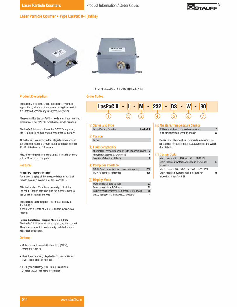
Laser Particle Counters Product Information / Order Codes
D44 www.stauff.com
Product Description
The LasPaC II-I (Inline) unit is designed for hydraulic applications, where continuous monitoring is essential. It is installed permanently in a hydraulic system.
Please note that the LasPaC II-I needs a minimum working pressure of 2 bar / 29 PSI for reliable particle counting.
The LasPaC II-I does not have the QWERTY keyboard, the LCD display, and an internal rechargeable battery.
All test results are saved in the integrated memory andcan be downloaded to a PC or laptop computer with theRS-232 interface or USB adapter.
�����������#�����������"�����Z��[�\���=����������������with a PC or laptop computer.
Features
Accessory - Remote DisplayFor a direct display of the measured data an optional remote display is available for the LasPaC II-I.
����������������""������������������!���� ��������LasPaC II-I and to start and stop the measurement byuse of the three push buttons.
The standard cable length of the remote display is2 m / 6.56 ft.A cable with a length of 5 m / 16.40 ft is available onrequest.
Hazard Conditions - Rugged Aluminium CaseThe LasPaC II-I inline unit has a rugged, powder coatedAluminum case which can be easily installed, even in hazardous conditions.
Options
� Moisture results as relative humidity (RH %), temperatures in °C
� Phosphate Ester (e.g. Skydrol®) or�����#��+�����;!�� �����������������_����
� ATEX (Zone II Category 3G rating) is available.Contact STAUFF for more information.
Laser Particle Counter � Type LasPaC II-I (Inline)
Front / Bottom View of the STAUFF LasPaC II-I
- I - M - 232 - D3 - W - I I LasPaC II M M 232 232 D3 D3 W W 30
� Moisture/ Temperature Sensor Without moisture/ temperature sensor O With moisture/ temperature sensor W
Please note: The moisture/ temperature sensor is not suitable for Phosphate Ester (e.g. Skydrol®) and Water � ;!�� ������
� Design Code Inlet pressure: 2 ... 400 bar / 29 ... 5801 PSI Drain reservoir/system: Atmosheric, zero back 30 pressure Inlet pressure: 10 ... 400 bar / 145 ... 5801 PSI Drain reservoir/system: Back pressure not 31 exceeding 1 bar / 14 PSI
Order Codes
� Series and Type Laser Particle Counter LasPaC II
� Version Inline I
� Fluid Compability`������{���[�������������� ������%���������������*� MPhosphate Ester (e.g. Skydrol®) E����#��+�����;!�� ������� G
� Computer Interface RS-232 computer interface (standard option) 232 RS-485 computer interface 485
� Display Mode PC driven (standard option) D3 Remote module + PC driven D2 Remote visual indicator (red/green) + PC driven D5 \�������=����#�������!�%�����`�����*� X

Diag
tron
ics
D
Laser Particle CountersProduct Information
www.stauff.com D45
Technical Data
Dimensions and Weight� LxWxH: 120 x 275 x 250 mm /
4.72 x 10.83 x 9.84 in � Weight: 4,80 kg / 10.58 lbs
Power Supply � Voltage range: 110 ... 240 V AC 12 ... 24 V DC
� European, UK and US power plug adaptors included
Calibration � Calibration: ISO Medium Test Dust (MTD) according to ISO 11 171:1999
� Analysis range: ISO 8-24, ISO 4406 Code, NAS 1638 Code 2-12, SAE AS 4059 Code 2-12
Pressure / Viscosity � Pressure range: Series 30: 2 ... 400 bar/ 29 ... 5801 PSI Series 31: 10 ... 400 bar/ 145 ... 5801 PSI
� Viscosity range: up to 400 cSt
Laser Sensors � High accuracy laser: 4 ... ����(c)
� �������������!�����|�������}���(c)
� `��������������| ~������~��?���?���@}�������}���(c)
� The ���#���"�������������������������������"�0,9 x 0,9 mm / .04 x .04 in
� The maximum concentration is ISO 4406 Code 24 (160.000 p/ml)
Laser Particle Counter � Type LasPaC II-I (Inline)
Accessories � Bottle sampling unit: 110 ml version (only for Mineral � � � {������[�������������� ����* 250 ml version (for Mineral Oil � � � ����[�������������� ������ a Phosphate Ester (e.g. Skydrol®)
compatible version of the 250 ml unit is available on request.)
Please contact STAUFF for details.� ������#���| ������#����%������*
Connections � Hose connections: Test coupling STAUFF Test 20 or comparable (M16 x 2)
Sample Volume � 8 ml (short) � 15 ml (normal) � 30 ml (dynamic) � 24 ml (bottle sampler) � 15 ml (continuous)
Permissible Temperature� Operating: +5 °C ... +80 °C / +41 °F ...+176 °F
Data Output� Cumulative particle counts, as well as cleanliness classes
according to ISO 4406 (1999) / SAE AS 4059 Rev.D (2001) and ISO 4406 (1191) / NAS 1638 (1964)
Max. Concentration� ISO 24
Data Storage� 600 tests
Fluid Compability� `������{����[�������������� ����� Phosphate Ester and Water Glycol compatible devices on
request
Computer Interface� RS-232 communication port as standard� RS-485 on request� USB adaptors included
Software� Downloading and storage of the data with included “LasPaC
II View” software. Further processing with Microsoft Excel® possible.
External Alarm� seperate wires in connector cable ( max. 24 V DC/AC, 1A)
Protection Rating � IP 55 protection rating: Dust protected and protected against water jets
Rear / Top View of the STAUFF LasPaC II-I Remote Display for the STAUFF LasPaC II-I

Laser Particle Counters Product Information / Order Codes
D46 www.stauff.com
Product Description
Analysis Everywhere - Bottle Sampling UnitIf a direct particle count on your system is not possible,the LasPaC II bottle sampler units allow you to take measurement samples for analysis at a later time.
Conditioning - The De-aeration Facility������!��������� ������!������������������������therefore a de-aeration process has been incorporatedinto the bottle sampling units.By evacuating the air from the sampling chamber,���������<���������� ������������������������ �������properly conditioned prior to sampling.
Your Choice - 110 ml or 250 ml SizeSTAUFF offers two sizes of bottle sampling units forthe LasPaC II devices: the 110 ml and the 250 ml units.
The 110 ml unit is supplied in an extra case including various accessories such as power supply, samplinghoses, pressure hoses, bottles (sample and waste)and adapters. It is designed for mobile applications andis only compatible with Mineral Oil and Petroleum based �����
The standard version of the 250 ml unit is compatible<����`������{������[�������������� ��������[���������Ester (e.g. Skydrol®) compatible version of the 250 ml unit is available on request. Please contact STAUFF fordetails.
The 250 ml bottle sampling unit is delivered with the required power supply.
Please note that the moisture / temperature sensor does not work in combination with bottle sampler devices.
Laser Particle Counter � Type Bottle Sampler
Bottle Sampling Unit 250 ml Bottle Sampling Unit 110 ml
- Bottle Sampler 110 LasPaC II
� Bottle Sampling Unit 110 ml Bottle Sampling Unit
suitable for Mineral Oil and Bottle Sampler 110[�������������� �������!
250 ml Bottle Sampling Unitsuitable for Mineral Oil and Bottle Sampler 250[�������������� �������!
250 ml Bottle Sampling Unitsuitable Phosphate Ester Bottle Sampler 250-E(e.g. Skydrol®)
Order Codes
� Type and Series Laser Particle Counter LasPaC II
Bottle Sampling Unit 110 ml and Accessories

Diag
tron
ics
D
Laser Particle CountersProduct Information / Order Codes
Product Description: Screen Filter An optional Screen Filter is available for heavily �������������!�����������#����������������������directly to the supply line and allows particle counts in ambient conditions where normally the contamination is too high for a reliable test.
������������������������������������"��������������cleanable.
Product Description
More Oil Analysis - Oil Saturation and Temperature���`������{����������=�_������#������������� ������<����is undesirable. Once the water exceeds a saturation level %��������������"���`������{��*����� ���������������������hazy. Above this level there is a danger of free water accumulating in the system. This can lead to corrosion and accelerated wear.
As an option, all LasPaC II devices provide accurate andrepeatable measurement of the saturation level of water in oil with the moisture / temperature sensor. The sensor is locatedinternally in a specially designed housing and is positioned in�����<������������������ �<�����
Simplicity - Saturation Level as a PercentageDifferent oils have different saturation levels. For this reason, measurements in % saturation is the best and mostpractical way. Of course these results can be converted toppm (parts per million) if the oil type saturation / temperature characteristics are known.
Additional Information - Oil Temperature ReadingsBeside the saturation level the optional moisture / temperaturesensor of the LasPaC II units has the ability to measure���� ������������������������<�����������������"������temperature for the RH (relative humidity / % saturation of water in oil) readings.
Both results, RH % and °C, are displayed on the main / testprogress screen and on the printed analysis.
Please note: Due to the temperature gradient existing betweenthe system tapping point and the RH / temperature module,the temperature reading can be 5° to 10° less than the actualsystem temperature, depending on operating conditions.The moisture / temperature sensor is not suitable for bottlesampling.
Saturation Levels����������""�����"�"����%���������#��*�<�����are more harmful than those of dissolved water, water levels should remain always well below the saturation point.
However, even water in solution can cause damage, and therefore every reasonable effortshould be made to keep saturation levels as low as possible.
There is no such thing as too little water.As a guideline, we recommend maintainingsaturation levels below 50 % in all equipment.
Different oils have different saturation levels, and % saturation is the best and most practicalmeasurement.
These results can be converted to ppm (partsper million), if the oil type saturation / temperature characteristic is known.
Saturation Point
$����#��
Free
Wat
erDi
ssol
ved
Wat
er
100 %
75 %
50 %
25 %
0 %
Moisture / Temperature Sensor
Laser Particle Counter � Accessories
Accessories / Spare Parts
Order Codes
� Type of Accessories / Spare PartsWaste hose 2 m / 6.56 ft LasPaC II - Waste hose 2mPressure hose 1,5 m / 4.92 ft SMS-20-1500-A-C6F��� ������#�������������%�������* LasPaC II - Bottle 100-C Set?�� ������#�������������%�������* LasPaC II - Bottle 250-C Set100 ml glass sample bottle (5 pieces) LasPaC II - Bottle 100 Set250 ml glass sample bottle (5 pieces) LasPaC II - Bottle 250 SetPrinter paper LasPaC II-P (5 pieces) LasPaC II - P-Printer Paper SetRS 232 to USB converter Adapter PPC-04/12-RS232-to-USB-CABAA������#��� LasPaC II - Screen Filter
www.stauff.com D47
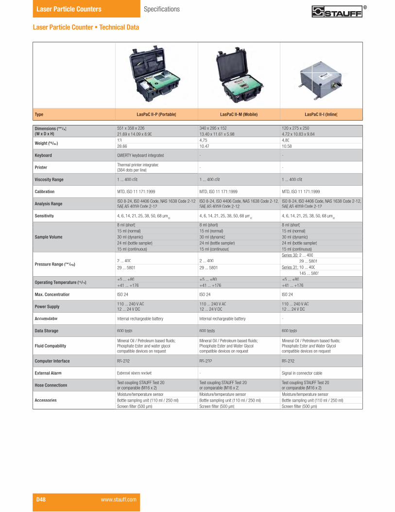
Laser Particle Counters ����#�������
D48 www.stauff.com
Dimensions (mm/in)(W x D x H)
551 x 358 x 226 340 x 295 x 152 120 x 275 x 25021.69 x 14.09 x 8.90 13.40 x 11.61 x 5.98 4.72 x 10.83 x 9.84
Weight (kg/lbs)13 4,75 4,8028.66 10.47 10.58
Keyboard QWERTY keyboard integrated - -
Printer Thermal printer integrated(384 dots per line) - -
Viscosity Range 1 ... 400 cSt 1 ... 400 cSt 1 ... 400 cSt
Calibration ������!"�##�#$#%#&&& ������!"�##�#$#%#&&& ������!"�##�#$#%#&&&
Analysis Range �!"�'*+/���!"�//:;�<����=>!�#;?'�<���+*#+�SAE AS 4059 Code 2-12
�!"�'*+/���!"�//:;�<����=>!�#;?'�<���+*#+�SAE AS 4059 Code 2-12
�!"�'*+/���!"�//:;�<����=>!�#;?'�<���+*#+�SAE AS 4059 Code 2-12
Sensitivity 4, 6, 14, 21, 25, 38, 50, 68 μm(c)4, 6, 14, 21, 25, 38, 50, 68 μm
(c)4, 6, 14, 21, 25, 38, 50, 68 μm
(c)
Sample Volume
8 ml (short) 8 ml (short) 8 ml (short)15 ml (normal) 15 ml (normal) 15 ml (normal)30 ml (dynamic) 30 ml (dynamic) 30 ml (dynamic)24 ml (bottle sampler) 24 ml (bottle sampler) 24 ml (bottle sampler)15 ml (continuous) 15 ml (continuous) 15 ml (continuous)
Pressure Range (bar/r PSI)2 ... 400 2 ... 400
!������?:% 2 ... 400 29 ... 5801
29 ... 5801 29 ... 5801 !������?#% 10 ... 400 145 ... 5801
Operating Temperature (°C/°F)+5 ... +80 +5 ... +80 +5 ... +80+41 ... +176 +41 ... +176 +41 ... +176
Max. Concentration �!"�+/ �!"�+/ �!"�+/
Power Supply 110 ... 240 V AC12 ... 24 V DC
110 ... 240 V AC12 ... 24 V DC
110 ... 240 V AC12 ... 24 V DC
Accumulator �����������������B���B������ �����������������B���B������ -
Data Storage 600 tests 600 tests 600 tests
Fluid Compability��������"�����G���������B���������H�Phosphate Ester and water glycol compatible devices on request
��������"�����G���������B���������H�Phosphate Ester and Water Glycol compatible devices on request
��������"�����G���������B���������HPhosphate Ester and Water Glycolcompatible devices on request
Computer Interface RS-232 RS-232 RS-232
External Alarm External alarm socket - Signal in connector cable
Hose Connections Test coupling STAUFF Test 20or comparable (M16 x 2)
Test coupling STAUFF Test 20 or comparable (M16 x 2)
Test coupling STAUFF Test 20or comparable (M16 x 2)
AccessoriesMoisture/temperature sensor Moisture/temperature sensor Moisture/temperature sensorBottle sampling unit (110 ml / 250 ml) Bottle sampling unit (110 ml / 250 ml) Bottle sampling unit (110 ml / 250 ml)!������N�������O::�X� !������N�������O::�X� !������N�������O::�X�
Type LasPaC II-P (Portable) LasPaC II-M (Mobile) LasPaC II-I (Inline)
Laser Particle Counter � Technical Data

Diag
tron
ics
D
Notes
www.stauff.com D49

Laser Particle Counters Product Information / Order Codes
D50 www.stauff.com
Product Description
The Laser Particle Monitor System LPM-1 is a laser based 4-channel inline particle monitor designed for the continuous monitoring of particle contamination. ����Z[`=�����������������������������������������"�������������~���(c)�������(c) ������~���(c) sizes applicable to the ISO 4406, ISO 11943 und ISO 11171 requirements for optical particle counters.����?����(c) channel is also provided for larger particle concentration information. Machine operators are alerted to changes in ��������������������������������������� �����!�������������������������"��������Z[`=���
The contamination level can be shown on the display or can be transmitted via the RS-232 serial port to a personal computer.With the ModBus-serial port the data can be transferred into a computer network or to an external display. The LPT Particle ���������������#���������������>=����������[���The LPM-1 system consists of a Laser Particle Transducer LPT and a Laser Interface Module LIM.
Laser Particle Monitor � Type LPM-1
LPT 1/-7/-9 without display LPT -4/-8/-0 with display
FLUID IN
IR-Link
IR-Link
Serial Connection PC (RS 232) Output: 0...5 V DCModBus (ASCII)
Display ISO 4406 plus additional info. Alarm at increasing Signal
Display ISO 4406 plus additional info. Alarm at decreasing Signal
FLUID OUT
LIM 1 LIM 4 with DisplayLIM 3 without Display LIM 5 with Display
FLUID IN
FIBER OPTIC CABLE
Functional diagram
IR-Linkfor Setup & Programmingfor Setup & Programming
Scope of Delivery
Each kit of LPM-1 includes:
� 1x Laser Particle Transducer LPT (optional)= �������@ ������}~ "�� !����������<������(9 ... 36 V DC required, not supplied)
� 1x Laser Interface Module LIM (optional)- LIM-1, includes 6 m / 19.69 ft interconnecting #������������- LIM-3, includes 6 m / 19.69 ft interconnecting #������������������<��@ ������}~ "����<��cable with 3-Pin connector - LIM-4, includes 6 m / 19.69 ft interconnecting #�������������������������&�������with 15-Pin connector - LIM-5, includes 6 m / 16.69 ft interconnecting #�������������������������&�������with 15-Pin connector
� 1x Quick Start Guide� 1x Operating Manual� 1x Software
- includes DDE server- hex and terminal logger for RS-232 - Palm shareware
- T1 - M4 -T1T1 M4M4LPM-1 DAV
� Laser Interface Module (LIM) Without LIM O LIM-1; PC connection RS-232 serial port M1 LIM-3; 8-channel (0 V ... 5 V DC) output, Modbus
PC connection RS-485 serial port M3
LIM-4; LED display with alarm contacts(for exceeding the set alarm level) M4
LIM-5; LED display with alarm contacts(for falling below the set alarm level) M5
� Dynamic Application Valve (DAV) Without Dynamic Application Valve O
Dynamic Application Valve DAV
Order Codes
� Series and Type Laser Particle Monitor LPM-1
� Laser Particle Transducer (LPT) Without LPT O LPT-1; 28 ... 500 bar / 400 ... 7250 PSI; without display T1
LPT-4; 28 ... 500 bar / 400 ... 7250 PSI; with display T4 LPT-7; 3,4 ... 83 bar / 50 ... 1200 PSI; without display T7
LPT-8; 3,4 ... 83 bar / 50 ... 1200 PSI; with display T8
LPT-9; 1,4 ... 13,8 bar / 20 ... 200 PSI; without display T9
LPT-0; 1,4 ... 13,8 bar / 20 ... 200 PSI; with display T0

Diag
tron
ics
D
Laser Particle CountersProduct Information / Order Codes
www.stauff.com D51
Technical Data
Channel Sizes � ~������~�����?� ��(c) (ISO MTD/ISO 11171)
Light Source� Laser diode
Sampling� Continuos online monitoring
Reproducibility � ± 0.5 ISO code (ISO 4406)���
Display� Optional local display available; presents ISO
codes and alarms
Power Supply� 9 ... 36 V DC @ 150 mA (power must be supplied to
instrument for operation)
Electrical Data and Output� RS-232; RS-485� 0 ... 5 V DC� Modbus� Alarms � Local and remote displays
Reports� Particles/ml; ISO 4406 codes 4, 6, 14 and
����������?� ��(c) (ISO MTD/ISO 11171)
Laser Particle Transducer � Type LPT-1
105,2(4.14)
62,7(2.47)
88,9
(3.5
0)
p yLaser Particle Transducer LPT-4/-8/-0 with display.
105,2(4.14)
49,2(1.94)
88,9
(3.5
0)
Laser Particle Transducer LPT-1/-7/-9 without display.
Product Description
The Laser Particle Transducer (LPT) contains the sensing device and electronics for detecting the level of contamina-tion.The laser based sensor uses light blocking technology for particle detection whereby particles passing through an ������ �<�����&������������"�����������������������to the particle size.The resultant particle concentration data from the LaserParticle Transducer (LPT) are sent to the Laser Interface`�����%Z�`*�������#��������������������#����������"the Laser Particle Transducer (LPT) has to be done throughthe IrDA port of any Palm with IRA capabilities.����Z�����[����������������%Z[�*������� �<�������������<���������"���������������������������������������� ��� �<�"�����!����������������<��������������������#��� �<range. For use with a dynamic or changing inlet pressure,please use the additional Dynamic Apllication Valve (DAV,please see on page D52).The pressure is reduced to near atmospheric for return to thehydraulic reservoir. The inlet pressure ranges from 1,4 barto 500 bar / 20 PSI to 7250 PSI in three models.The Laser Particle Transducer (LPT) is optionally available with or without a LED display.The three digit display shows the selected ISO code value or other function parameters.
The following types of Laser Particle Transducers (LPT) are available:
� LPT-1 28 ... 500 bar (400 ... 7250 PSI), without LED display
� LPT-4 28 ... 500 bar (400 ... 7250 PSI), with LED display
� LPT-7 3,4 ... 83 bar (50 ... 1200 PSI), without LED display
� LPT-8 3,4 ... 83 bar (50 ... 1200 PSI), with LED display
� LPT-9 1,4 ... 13,8 bar (20 ... 200 PSI), without LED display
� LPT-0 1,4 ... 13,8 bar (20 ... 200 PSI), with LED display
Process Connections� SAE-4 (7/16–20 UNF)
Sensor Flow Rate� 50 ... 500 ml/min (0.01 ... 0.1 US GPM) through
�������<�������������������""�������������� �<rate monitoring wit alarms.
Media Compatibility� Suitable for mineral based hydraulic and lubrication
oils; compatibility with synthetic media (Phosphate Ester) on request
Viscosity� 2 ... 424 cSt at ambient temperature of
+25 °C ±2 °C / +77 °F ±3.6 °F
Operating Pressure� 1,4 bar ... 500 bar / 20 PSI ... 7250 PSI
Permissible Temperature� Storage: -40°C ... +85°C / -40°F ... +185°F� Ambient: -20°C ... +60°C / -4°F ... +140°F � Operating: -10°C ... +60°C / +14°F ... +140°F
Protection Rating� IP 67 protection rating: Dust tight and protected against
powerful water jets; even immersion (up to 1 m / 3.28 ft) ���<������������������������#���������������"���������and time
Flow Pattern
Dimensional drawings: All dimensions in mm (in).
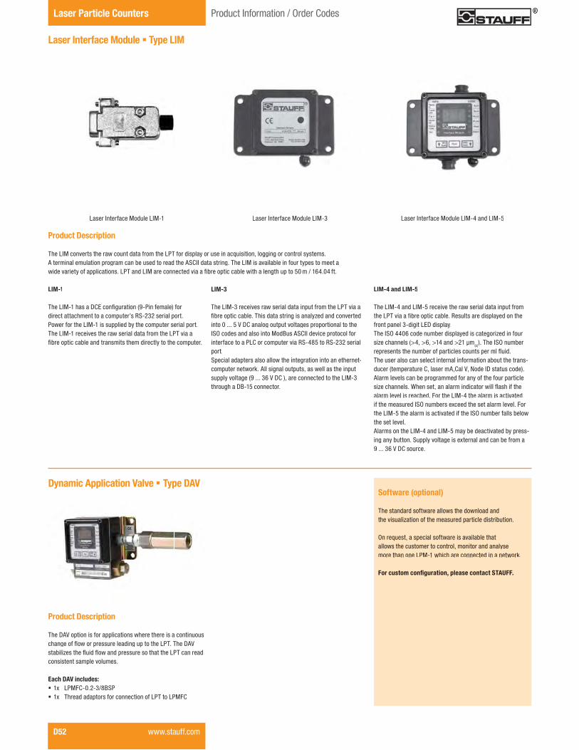
Laser Particle Counters Product Information / Order Codes
D52 www.stauff.com
Laser Interface Module � Type LIM
Laser Interface Module LIM-1
Dynamic Application Valve � Type DAV
Product Description
The DAV option is for applications where there is a continuous �������"� ��<������������������������������Z[�����������������X������� ����� ��<��������������������������Z[����������consistent sample volumes.
Each DAV includes:� 1x LPMFC-0.2-3/8BSP� 1x Thread adaptors for connection of LPT to LPMFC
LIM-1
����Z�`=���������\$���#����������%�=[���"����*�"���direct attachment to a computer’s RS-232 serial port. Power for the LIM-1 is supplied by the computer serial port.The LIM-1 receives the raw serial data from the LPT via a#��������������������������������������!����������������
LIM-3
The LIM-3 receives raw serial data input from the LPT via a #��������������������������������������!X����������������into 0 ... 5 V DC analog output voltages proportional to theISO codes and also into ModBus ASCII device protocol for interface to a PLC or computer via RS-485 to RS-232 serial port.Special adapters also allow the integration into an ethernet-computer network. All signal outputs, as well as the input supply voltage (9 ... 36 V DC ), are connected to the LIM-3 through a DB-15 connector.
Laser Interface Module LIM-4 and LIM-5Laser Interface Module LIM-3
Software (optional)
The standard software allows the download andthe visualization of the measured particle distribution.
On request, a special software is available thatallows the customer to control, monitor and analysemore than one LPM-1 which are connected in a network.
�������������� ����������������������������
Product Description
The LIM converts the raw count data from the LPT for display or use in acquisition, logging or control systems. A terminal emulation program can be used to read the ASCII data string. The LIM is available in four types to meet a <����������!��"�������������Z[������Z�`�������������������#��������������<���������������������������~��~�"��
LIM-4 and LIM-5
The LIM-4 and LIM-5 receive the raw serial data input from ����Z[��������#���������������>���������������!����������front panel 3-digit LED display.The ISO 4406 code number displayed is categorized in four ��X���������%�~��������~������?����(c)). The ISO number�����������������������"��������������������� ������The user also can select internal information about the trans-ducer (temperature C, laser mA,Cal V, Node ID status code).Alarm levels can be programmed for any of the four particle ��X����������+��������������������������<�� ������"����alarm level is reached. For the LIM-4 the alarm is activated if the measured ISO numbers exceed the set alarm level. For the LIM-5 the alarm is activated if the ISO number falls belowthe set level.Alarms on the LIM-4 and LIM-5 may be deactivated by press-ing any button. Supply voltage is external and can be from a9 ... 36 V DC source.

Diag
tron
ics
D
Laser Particle CountersProduct Information / Order Codes
www.stauff.com D53
Check Oil Analysis STFC and Oil Sampling Kit SFSK
Product Description
Fluid analysis is a crucial component of any oil management program. Early detection of potential problems can prevent costly repairs and downtime. STAUFF SFSK oil analysis kits provide the tools to take a sample from a STAUFF test coupling or directly from a reservoir or sump.For this the supplied hose is directly connected to the test �������<����������������������� ��������#����������������=plied vials.But there is also the possibility to draw up the sample directly "���������&�<����������������������#�������������������This sample set is available in two versions with BSP and NPT test couplings.
The STAUFF Check Fluid Analysis Kit includes complete laboratory analysis of your oil sample as part of the initial pur-chase price of the kit. Each kit includes an ultra-clean bottle with pre-addressed mailer and sample information sheet.
Scope of Delivery (SFSK)
� Contains vacuum pump for drawing samples of oil equipment� 1 m / 3.28 ft hose for insertion into tank� Two sample bottles� STAUFF test points and adaptor allows oil sample to be
taken from STAUFF Test 20 test points
Components of SFSK-1 and SFSK-2:
SFSK-1� 1x Fluid Sample Pump FSP-38� 1x Hose adaptor SHA-20-5,5mm� 1 m / 3.28 ft Push on 1/4” hose� 1x SMK20-1/4NPT-VD-C6F� 1x SMK20-7/16UNF-VE-C6F� Sample bottles
SFSK-2� 1x Fluid Sample Pump FSP-38� 1x Hose adaptor SHA-20-5,5mm� 1 m / 3.28 ft Push on 1/4” hose� 1x SMK20-G1/4-PC-C6F� 1x SMK20-M10x1-PA-C6F� Sample bottles
SFSK-1
Order Codes
� Series and Type NPT type SFSK-1
BSP type SFSK-2
STFC-10
� Description Carton of 10 bottles STFC-10
Single test bottle STFC-01
STFC - Test carried out include:
� Spectographic analysis - 19 elements for wear metals,contaminants and additives
� Viscosity - the kinematic viscosity reported in centistokes (cSt)� Visible debris analysis - microscopic examination of any
visible debris in the sample� Total acrid number (TAN)� Particle count - to determine the cleanliness of the system� Karl Fisher (KF) - to determine the exact concentration of
water present in the oil
Oil Sampling Kit SFSKCheck Oil Analysis STFC
Oil Analysis Reports
In addition to a printed report, the STAUFF Check FluidAnalysis service includes access to your test reports on theInternet.Your reports are hosted on a secure server that you canaccess with your user ID and password. All that is required is a connection to the internet and a compatible browser. Youcan view all your current and previous test results for all of themachines you are monitoring. Track the effectiveness of your oil management program and generate detailed managementsummary reports.
Review Oil Analysis Results
View oil analysis sample reports, test results, trending graphs and recommendations. Access data that was traditionally ac-cessible only to the laboratory, including, IR spectra, TAN andTBN titration plots, as well as, GC chromatograms.Enjoy the best possible turn-around of your oil analysis samples by viewing data on-line and in real-time with your oil analysis laboratory.Improve time management by receiving e-mail alerts notifying you when recently completed samples indicate an equipment problem when corrective action is required.

The continuous monitoring of critical hydraulic systems has become normal in today’s market. The automatic and timely detection of problems in hydraulic systems can predict component failure and thereby eliminate catastrophic system failures. The advent of automated processes systems have made continuous monitoring and control components indispensible.
With the STAUFF line of industrial and mobile sensor, it is possible to continuously monitor and control your machine and process. The wide range of STAUFF transmitters and switches available, enables proper fit to any application need.
The STAUFF line of simple pressure and temperature switches are factory set, or adjustable via a screw. The switches can be ordered normally open, normally closed, or SPDT.
The STAUFF transmitters are available in many pressure and temperature ranges. Output signals are available in 4 ... 20 mA and 0 ... 10 V. Other signals are available on many items. The process connections are available in NPT, SAE, BSP for international use.
All sensors can be ordered with flying leads, DIN connectors or other options to fit the environment.
Sensors and Switches
Sensors and Switches Introduction
D54 www.stauff.com
NoAm Version Diagtronics January 2013.indd 54 22.01.2013 11:52:57

Diag
tron
ics
D
Level-Temperature Switch § Type SLTS
Product Description
The STAUFF Level-Temperature Switches (SLTS Series) are unique in their design and modularity. One of the greatestadvantages is the ability of the end-user to adjust the switching level. The internal support wire carrying the level and temperature switches makes it a simple and quick job to change the level switch position.
Level contact positions (L2, H) are set as given in the order code. They can be adjusted individually later on.Please consider a minimum distance of 40 mm / 1.57 in between the switching points.
Features
§ Suitable for Mineral Oil and HFC fluids, other fluids on request
§ Either 1 or 2 level contacts available § 1 integrated temperature sensor (optional) § Standard electrical function: Level contacts: Normally closed, opens with falling level Temperature contacts: Normally closed, opens with rising temperature
STAUFF Level-Temperature Switches SLTS are available with other electrical functions on request.
Options
§ 1 NPT and others availble on request § max. 115 Volt switching (for thread N16 only)
Technical Data
Materials § Stem: Brass § Float/Sealing: NBR (Buna-N®)
§ Max. operating temp.: +80 °C / +176 °F
Electrical Data and Output § Max. current level contact: 0.5 A § Max. current temp. contact: 2.0 A § Contact load level contact: 10 VA § Max. operating voltage: (See ordering code)
§ Specific gravity of fluid: ≥0,8 kg/dm3
§ Hysteresis: +18 °C / +64.4 °F
Protection Rating § IP 65 protection rating: Dust tight and protected against water jets
SLTS 12 - O - H41 - L251 - B12 - G048 - M12
Order Codes
Hex 36
M3 ground
34(1
.34)
16(.63) 45
(1.77)
41(1.61) L2
L1
Upper level contact H
Lower level contact L2
G
25(.98)
Ø 23
,5(.9
3)
23,5(.93)
Ø 11
(.43)
(1.42)4 2
31
H
L
q
two level contacts one temperature contact
J
H
L
Wiring Scheme
4 2
31
one level contactone temperature contact
H or L
J
eL2 (Lower Level Contact) Without lower level contact O 251 mm / 9.88 in (SLTS 12 only) L251 403 mm / 15.87 in (SLTS 18 only) L403 Other level contact positions on request (only for SL)
f Process Connection G3/4 (standard option) B12 1 NPT N16
Note: Others on request
g Voltage (Volt AC/DC) 48 Volt max. (standard option) G048 115 Volt max. (for thread N16 only) G115
h Electrical Connection similar DIN VDE 0627 / IEV 61984 CB M12 pin terminal M12
Contact Life Time
Due to their design Reed contacts have a very high life expectancy. However, it is worthwhile to note the following information.
Contact Protection
To reduce the high reverse voltage produced when a reed switch opens, the following contact protection can be applied. § DC voltage: a diode parallel to the load, see figure A § AC voltage: a RC-network parallel to the load, see figure B and table below
Open contact voltage V 10 VA 25 VA 50 VA 75 VA 100 VAR (Ω) C (µF) R (Ω) C (µF) R (Ω) C (µF) R (Ω) C (µF) R (Ω) C (µF)
24 22 0,022 1 0,1 1 0,47 1 1 1 148 120 0,0047 22 0,022 1 0,1 1 0,47 1 0,47110 470 0,001 120 0,0047 22 22 22 0,047 22 0,1
A Contact
Last load
Protective diode
B Contact
Last load
RC-Network
(.14)3.5
Product Information / Order Codes Sensors and Switches
www.stauff.com D55Dimensional drawings: All dimensions in mm (in).
a Series and Type Level-Temperature Switch SLTS
b Stem Length L1: 305 mm / 12 in L2: 251 mm / 9.88 in 12 L1: 457 mm / 18 in L2: 403 mm / 15.87 in 18 Custom stem lengths on request * SL
c Switching Temperature Without temperature switch O +60 °C / +140 °F 140 +70 °C / +158 °F 158
d H (Upper Level Contact) Without upper level contact O 41 mm / 1.61 in H41 Other level contact positions on request (only for SL)
* Note: If you choose the option SL, please consult STAUFF for further information.
NoAm Version Diagtronics January 2013.indd 55 22.01.2013 11:53:00

Product Description
Efficient and inexpensive indication of level and temperature.
Level contact positions (L2, H) are set as given in the order code. They can be adjusted individually later on.Please consider a minimum distance of 50 mm / 1.97 in between the switching points.
Features
§ Threads: G1/2, 7/8–14 UNF, M20 x 1,5 § Stem length available from 140 ... 457 mm / 5.5 ... 18.00 in § Electrical connection M12 / 4-Pin terminal
Technical Data
Materials § Connector: Anodized Aluminium § Stem: Brass § Float: Polyurethane § Sealing: NBR (Buna-N®)
Electrical Connection § Connector type: M12 x 1 / 4-Pin
§ Max. operating pressure:1 bar / 14.5 PSI
Permissible Temperature § Operating: -20 °C ... +80 °C / -4 °F ... +176 °F
§ Specific gravity of fluid: ≥0,8 kg/dm3
Electrical Data and Output § Level contact type: K40 § Max. operating voltage: 36 V § Max. current: 0.5 A § Contact load: 5 VA
Protection Rating § IP 67 protection rating: Dust tight and protected against powerful water jets; even immersion (up to 1 m / 3.28 ft) in water is possible under defined conditions of pressure and time
SW 27(Hex1.06)
M12
x1 G
Ø 18
(.7)
45(1.77)
*
H=min. 30(1.18)
L min. 50(1.97)
32(1.26)
Stem length = max. 457(17.99)
Eolastic sealing for thread option G1/2 and M20 x 1,5 O-ring for thread option 7/8–14 UNF
3,5(.14)
SLTSA 12 - O - H60 - L255 - U10 - G036 - M12
1
2
34
Wiring Scheme
L1
L2
1 +24 V DC
4
2
3
1
2
34
Order Codes
a Series and Type Level-Temperature Switch Aluminium SLTSA
b Stem Lengths 140 mm / 5.51 in 55 170 mm / 6.69 in 67 215 mm / 8.46 in 85 280 mm / 11.02 in 11 305 mm / 12.01 in 12 370 mm / 14.57 in 146 457 mm / 18.00 in 18
c Switching Temperature Without temperature switch O
d H (Upper Level Contact) 30 mm / 1.18 in (only for stem length code 55) H30 50 mm / 1.97 in (only for stem length code 67) H50 60 mm / 2.36 in (only for stem length codes 55, 12, 18) H60
85 mm / 3.35 in (only for stem length code 85) H85 90 mm / 3.54 in (only for stem length codes 67, 12, 18) H90
135 mm / 5.31 in (only for stem length code 85) H135 200 mm / 7.87 in (only for stem length code11) H200 290 mm / 11.42 in (only for stem length code 146) H290
eL (Lower Level Contact) 90 mm / 3.54 in (only for stem length code 55) L90 120 mm / 4.72 in (only for stem length code 67) L120 165 mm / 6.50 in (only for stem length code 85) L165 230 mm / 9.06 in (only for stem length code 11) L230 255 mm / 10.04 in (only for stem length code 12) L255 320 mm / 12.60 in (only for stem length code 146) L320 407 mm / 16.02 in (only for stem length code 18) L407
f Process Connection G1/2 B08 7/8–14 UNF (standard option) U10 M20 x 1,5 M20
g Voltage 36 Volt max. G036
h Electrical Connection M12 / 4-Pin terminal M12
Level-Temperature Switch Aluminium § Type SLTSA
* 14 (.55) for thread option G1/2 and M20 x 1,5 13 (.51) for thread option 7/8–14 UNF
D56 www.stauff.com Dimensional drawings: All dimensions in mm (in).
Sensors and Switches Product Information / Order Codes
NoAm Version Diagtronics January 2013.indd 56 22.01.2013 11:53:06
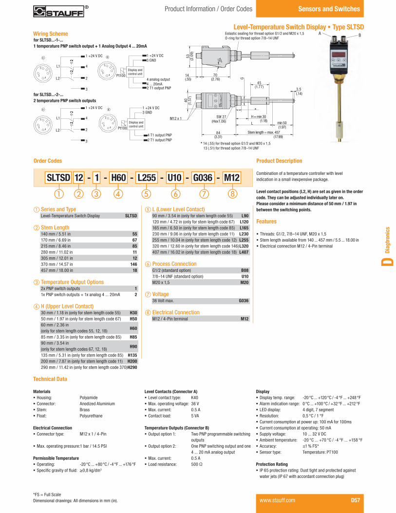
Diag
tron
ics
D
Product Information / Order Codes Sensors and Switches
Unit
1 +24 VDC
3 GND
4 Analog Output 4-20mA
2 T1 Output PNP
43
2
1
B
Display
and
Control
Pt100
Level-Temperature Switch Display § Type SLTSD
Product Description
Combination of a temperature controller with level indication in a small inexpensive package.
Level contact positions (L2, H) are set as given in the order code. They can be adjusted individually later on.Please consider a minimum distance of 50 mm / 1.97 in between the switching points.
Features
§ Threads: G1/2, 7/8–14 UNF, M20 x 1,5 § Stem length available from 140 ... 457 mm / 5.5 ... 18.00 in § Electrical connection M12 / 4-Pin terminal
SLTSD 12 - 1 - H60 - L255 - U10 - G036 - M12
Order Codes
DisplayL1
L2
4
2
3
1 +24 VDC
1
2
34
2 T2 Output PNP
4 T1 Output PNP
3 GND
1 +24 VDCB
and
Control
UnitPt100
A
43
2
1
Wiring Schemefor SLTSD...-1-...1 temperature PNP switch output + 1 Analog Output 4 ... 20mA
5340
(1.5
7)
10°
14(.55)
84(3.31)
L
H = min 30
70(2.76)
45(1.77)
G
(.14)
(2.0
9)
(1.18)
(1.97)min 50
(17.99)Stem length = max. 457
3.5
M12 x 1
1 +24 V DC3 GND
4 analog output 4 ... 20mA2 T1 output PNP
Pt100
for SLTSD...-2-...2 temperature PNP switch outputs
1 +24 V DC
Pt100
4
2
3
1 +24 V DC3 GND
4 T1 output PNP2 T1 output PNP
L1
L2
Display andcontrol unit
Display andcontrol unit
BA
a Series and Type Level-Temperature Switch Display SLTSD
b Stem Length 140 mm / 5.51 in 55 170 mm / 6.69 in 67 215 mm / 8.46 in 85 280 mm / 11.02 in 11 305 mm / 12.01 in 12 370 mm / 14.57 in 146 457 mm / 18.00 in 18
c Temperature Output Options 2x PNP switch outputs 1 1x PNP switch outputs + 1x analog 4 ... 20mA 2
d H (Upper Level Contact) 30 mm / 1.18 in (only for stem length code 55) H30 50 mm / 1.97 in (only for stem length code 67) H50 60 mm / 2.36 in (only for stem length codes 55, 12, 18) H60
85 mm / 3.35 in (only for stem length code 85) H85 90 mm / 3.54 in (only for stem length codes 67, 12, 18) H90
135 mm / 5.31 in (only for stem length code 85) H135 200 mm / 7.87 in (only for stem length code 11) H200 290 mm / 11.42 in (only for stem length code 370) H290
eL (Lower Level Contact) 90 mm / 3.54 in (only for stem length code 55) L90 120 mm / 4.72 in (only for stem length code 67) L120 165 mm / 6.50 in (only for stem length code 85) L165 230 mm / 9.06 in (only for stem length code 11) L230 255 mm / 10.04 in (only for stem length code 12) L255 320 mm / 12.60 in (only for stem length code 146) L320 407 mm / 16.02 in (only for stem length code 18) L407
f Process Connection G1/2 (standard option) B08 7/8–14 UNF (standard option) U10 M20 x 1,5 M20
g Voltage 36 Volt max. G036
h Electrical Connection M12 / 4-Pin terminal M12
DisplayL1
L2
4
2
3
1 +24 VDC
1
2
34
2 T2 Output PNP
4 T1 Output PNP
3 GND
1 +24 VDCB
and
Control
UnitPt100
A
43
2
1
1 +24 V DC
4
2
3
L1
L2
Eolastic sealing for thread option G1/2 and M20 x 1,5 O-ring for thread option 7/8–14 UNF
*
* 14 (.55) for thread option G1/2 and M20 x 1,5 13 (.51) for thread option 7/8–14 UNF
SW 27(Hex1.06)
Technical Data
Materials § Housing: Polyamide § Connector: Anodized Aluminium § Stem: Brass § Float: Polyurethane
Electrical Connection § Connector type: M12 x 1 / 4-Pin
§ Max. operating pressure:1 bar / 14.5 PSI
Permissible Temperature § Operating: -20 °C ... +80 °C / -4 °F ... +176 °F § Specific gravity of fluid: ≥0,8 kg/dm3
Level Contacts (Connector A) § Level contact type: K40 § Max. operating voltage: 36 V § Max. current: 0.5 A § Contact load: 5 VA
Temperature Outputs (Connector B) § Output option 1: Two PNP programmable switching outputs
§ Output option 2: One PNP switching output and one 4 ... 20 mA analog output
§ Max. current: 0.5 A § Load resistance: 500 Ω
Display § Display temp. range: -20 °C ... +120 °C / -4 °F ... +248 °F § Alarm indication range: 0 °C ... +100 °C / +32 °F ... +212 °F § LED display: 4 digit, 7 segment § Resolution: 0,5 °C / 1 °F § Current consumption at power up: 100 mA for 100ms § Current consumption at operating: 50 mA § Supply voltage: 10 ... 32 V DC § Ambient temperature: -20 °C ... +70 °C / -4 °F ... +158 °F § Accuracy: ±1 % FS* § Sensor type: Temperature: PT100
Protection Rating § IP 65 protection rating: Dust tight and protected against water jets (IP 67 with accordant connection plug)
www.stauff.com D57*FS = Full ScaleDimensional drawings: All dimensions in mm (in).
NoAm Version Diagtronics January 2013.indd 57 22.01.2013 11:53:12

D58 www.stauff.com
Pressure Switch § Type SPW-...-NC/NO
Product Description
The SPW Mechanical Pressure Switch is available in a variety of pressure ranges. This durable unit has an adjustable set point that is easily changed by using the adjustment screw which is located under the protective cap.
Features
§ Normally open, normally closed § Pressure ranges available up to 206,84 bar / 3000 PSI § G1/4 and 1/4 NPT process connection § NBR (Buna-N®) sealings § Steel, zinc plated § Spade terminal connection
Options
§ G1/8, 1/8 NPT and 7/16–20 UNF process connections § FPM (Viton®) and EPDM sealings on request § Flying leads with shrink tubing, fl ying leads, rubber boot, Deutsch connector, weather pack connector female/male and IP option on request
§ 316 Stainless Steel
Technical Data
Materials § Body: Steel, zinc plated or 316 Stainless Steel
§ Connector: Polyamide
Electrical Data and Output § Switching function: Normally open (NO), normally closed (NC)
§ Cycle rate: 30 CPM § Mechanical life: 2000000 operations § Max. electrical rating: 100 VA
Permissible Temperatures § NBR (Buna-N®): -9 °C ... +110 °C / +15 °F ... +230 °F § FPM (Viton®) : -18 °C ... +110 °C / 0 °F ...+230 °F § EPDM: -40 °C ... +110 °C / -40 °F ...+230 °F
Process Connection § G1/8, G1/4, 1/8 NPT, 1/4 NPT and 7/16–20UNF
Electrical Connection § Spade terminals
Protection Rating § IP 00 protection rating
SPW - P00500 - N04 - NO - SP -
Order Codes
Version Pressure Maximum Burst Repeatability AverageRange (bar/PSI) Pressure (bar/PSI) Pressure (bar/PSI) Deadband
P000601,03 ... 4,14 413,69 620,53 ±0,10 bar + 3 % of setting 0,21 bar + 5 % of setting15 ... 60 6000 9000 ±1.5 PSI + 3 % of setting 3 PSI + 5 % of setting
P001502,76 ... 10,34 413,69 620,53 ±0,17 bar + 3 % of setting 0,35 bar + 6 % of setting40 ... 150 6000 9000 ±2.5 PSI + 3 % of setting 5 PSI + 6 % of setting
P002755,17 ... 18,96 413,69 620,53 ±0,26 bar + 3 % of setting 0,48 bar + 8 % of setting75 ... 275 6000 9000 ±3.75 PSI + 3 % of setting 7 PSI + 8 % of setting
P00500*10,34 ... 34,47 413,69 620,53 ±0,34 bar + 3 % of setting 0,69 bar + 10 % of setting150 ... 500 6000 9000 ±5 PSI + 3 % of setting 10 PSI + 10 % of setting
P0080018,96 ... 55,16 413,69 620,53 ±0,55 bar + 3 % of setting 10,3 bar + 11 % of setting275... 800 6000 9000 ±8 PSI + 3 % of setting 15 PSI + 11 % of setting
P01100*27,58 ... 75,84 413,69 620,53 ±0,90 bar + 3 % of setting 2,07 bar + 12 % of setting400 ... 1100 6000 9000 ±13 PSI + 3 % of setting 30 PSI + 12 % of setting
P03000*68,95 ... 206,84 413,69 620,53 ±2,41 bar + 3 % of setting 4,83 bar + 14 % of setting1000 ... 3000 6000 9000 ±35 PSI + 3 % of setting 70 PSI + 14 % of setting
Pressure Ranges
43(1
.69)
9(.3
5)
14(.55)
SW 24(Hex .94)
a Series and Type Mechanical Pressure Switch SPW
b Version 1,03 ... 4,14 bar / 15 ... 60 PSI P00060 2,76 ... 10,34 bar / 40 ... 150 PSI P00150 5,17 ... 18,96 bar / 75 ... 275 PSI P00275 10,34 ... 34,47 bar / 150 ... 500 PSI (standard option)
P00500
18,96 ... 55,16 bar / 275 ... 800 PSI
P00800
27,58 ... 75,84 bar / 400 ... 1100 PSI (standard option)
P01100
69,95 ... 206,84 bar / 1000 ... 3000 PSI (standard option)
P03000
c Process Connection G1/8 B02 G1/4 B04 1/8 NPT N02 1/4 NPT (standard option) N04 7/16–20 UNF U04
d Switching Outputs Normally open (standard option) NO Normally closed NC
eElectrical Connection Spade terminals (standard option) SP Flying leads F Flying leads with shrink tubing FL Deutsch DT04-3P / 3-Pin D Rubber boot RB Weather pack connector female WF Weather pack connector male WM IP Option (IP 66) IP
Note: IP Option requires a fi xed set point indicate at the end of part number.
f Body Material Steel, zinc plated (standard option) (none) 316 Stainless Steel W5
Wiring Scheme
1
1 2
2
Wiring diagram normally open
Wiring diagram normally closed
* Standard optionDimensional drawings: All dimensions in mm (in).
Sensors and Switches Product Information / Order Codes
NoAm Version Diagtronics January 2013.indd 58 22.01.2013 11:53:16

Diag
tron
ics
D
www.stauff.com D59* Standard optionDimensional drawings: All dimensions in mm (in).
Pressure Switch § Type SPW-SD
Product Description
The SPW-SD Mechanical SPDT Pressure Switch is available in a variety of pressure ranges. This durable unit has an adjustable set point that is easily changed by using the adjustment screw which is located under the protective cap.
Features
§ SPDT switching function § Pressure ranges available up to 344,74 bar / 5000 PSI § G1/4 and 1/4 NPT process connection § NBR (Buna-N®) sealings § Steel, zinc plated § Spade terminal connection
Options
§ G1/8, 1/8 NPT and 7/16–20 UNF process connections § FPM (Viton®) and EPDM sealings on request § Flying leads with shrink tubing, fl ying leads, Deutsch connector, weather pack connector female/male and IP option on request
§ 316 Stainless Steel
SPW - SD - P00300 - N04 - DIN -
Order Codes
a Series and Type Mechanical Pressure Switch SPW
b Switching Function SPDT SD
c Version 0,69 ... 2,07 bar / 10 ... 30 PSI P00030 1,72 ... 5,17 bar / 25 ... 75 PSI P00075 4,48 ... 20,68 bar / 65 ... 300 PSI (standard option)
P00300
17,24 ... 68,95 bar / 250 ... 1000 PSI (standard option)
P01000
68,95 ... 206,84 bar / 1000 ... 3000 PSI (standard option)
P03000
172,37 ... 344,74 bar / 2500 ... 5000 PSI
P05000
Version Pressure Maximum Burst Repeatability AverageRange (bar/PSI) Pressure (bar/PSI) Pressure (bar/PSI) Deadband
P000300,69 ... 2,07 413,69 620,53 ±0,10 bar + 2 % of setting 0,24 bar + 11 % of setting10 ... 30 6000 9000 ±1.5 PSI + 2 % of setting 3.5 PSI + 11 % of setting
P000751,72 ... 5,17 413,69 620,53 ±0,17 bar + 2 % of setting 0,24 bar + 11 % of setting25 ... 75 6000 9000 ±2.5 PSI + 2 % of setting 3.5 PSI + 11 % of setting
P00300*4,48 ... 20,68 413,69 620,53 ±0,34 bar + 2 % of setting 1,38 bar + 11 % of setting65 ... 300 6000 9000 ±5 PSI + 2 % of setting 20 PSI + 11 % of setting
P01000*17,24 ... 68,95 413,69 620,53 ±1,03 bar + 2 % of setting 3,10 bar + 12 % of setting250 ... 1000 6000 9000 ±15 PSI + 2 % of setting 45 PSI + 12 % of setting
P03000*68,95 ... 206,84 413,69 620,53 ±2,07 bar + 2 % of setting 4,83 bar + 12 % of setting1000... 3000 6000 9000 ±30 PSI + 2 % of setting 70 PSI + 12 % of setting
P05000172,37... 344,74 413,69 620,53 ±3,45 bar + 2 % of setting 9,65 bar + 13 % of setting2500 ... 5000 6000 9000 ±50 PSI + 2 % of setting 140 PSI + 13 % of setting
Pressure Ranges
35
(1.38)
88(3
.46)
55(2
.17)
76(2
.99)
Wiring Scheme
SW 28(Hex 1.10)
Technical Data
Materials § Body: Steel, zinc plated or 316 Stainless Steel
§ Connector: Polyamide
Electrical Data and Output § Switching function: SPDT § Cycle rate: 20 CPM § Mechanical life: 2000000 operations § Max. electrical rating: 5 A at 125/250 V AC, 5 A resistive / 3 A inductive at 28 V DC
Permissible Temperatures § NBR (Buna-N®): -9 °C ... +85 °C / +15 °F ... +185 °F § FPM (Viton®): -18 °C ... +85 °C / 0 °F ... +185 °F § EPDM: -23 °C ... +85 °C / -10 °F ... +185 °F
Process Connections § G1/8, G1/4, 1/8 NPT, 1/4 NPT and 7/16–20UNF
Electrical Connection § DIN EN 175301-803 form A (DIN 43650-A)
Protection Rating § IP 65 protection rating: Dust tight and protected against water jets
1
2 normally closed
3 normally open
d Process Connection G1/8 B02 G1/4 B04 1/8 NPT N02 1/4 NPT (standard option) N04 7/16–20 UNF U04
eElectrical Connection Flying leads F Flying leads with shrink tubing FL DIN EN 175301-803A (DIN 43650-A) (standard option) DIN
Deutsch DT04-3P / 3-Pin D Weather pack connector female WF Weather pack connector male WM IP Option (IP 66) IP
f Body Material Steel, zinc plated (standard option) (none) 316 Stainless Steel W5
Product Information / Order Codes Sensors and Switches
NoAm Version Diagtronics January 2013.indd 59 22.01.2013 11:53:18

Pressure Transmitters § Type SPT
Product Description
The SPT Pressure Transmitter is designed for many industrial and OEM pressure measurement applications.The SPT pressure transmitters convert applied pressurefrom 1,03 bar up to 689,48 bar / 15 PSI up to 10000 PSI into the corresponding output signals. The SPT Series provides resistance to vibration, shock, wide temperature variations and many other extreme environmental conditions that are typical of industrial and OEM applications.
Features
§ Stainless Steel housing construction § L-plug DIN EN 175301-803A (DIN 43650-A) electrical connection
§ Pressure ranges up to 689,48 bar / 10000 PSI § G1/4 or 1/4 NPT process connection § Output signal 4 ... 20 mA § Non-linearity ≤ ±0.5 % BFSL § Environmental protection of IP 65 (IP 65 protection rating: Dust tight and protected against water jets)
§ Protection against incorrect polarity, short circuits and over-voltage
§ Temperature compensated § Long term stability
Options
§ Mini L-plug DIN EN 175301-803C, M12 x 1 and fl ying lead electrical connections
§ 1/2 NPT and 7/16–20 UNF process connections § Output signals 0 ... 5 V, 0 ... 10 V, 1 ... 5 V and 0,5 ... 4,5 V ratiometric on request
§ Non-linearity ≤ ± 0.25 % BFSL § Environmental protection of IP 67(IP 67 protection rating: Dust tight and protected againstpowerful water jets; even immersion (up to 1 m / 3.28 ft) in water is possible under defi ned conditions of pressure and time)
§ Extended temperature option on request-30 °C ... +100 °C / -22 °F ... +212 °F
Order Codes
Sensors and Switches Product Information / Order Codes
D60 www.stauff.com
SPT - P00300 - N04 - 420A - DIN - - X
a Series and Type Pressure Transmitter SPT
b Version 0 ... 1,03 bar / 0 ... 15 PSI P00015 0 ... 1,72 bar / 0 ... 25 PSI P00025 0 ... 2,07 bar / 0 ... 30 PSI P00030 0 ... 3,45 bar / 0 ... 50 PSI P00050 0 ... 6,89 bar / 0 ... 100 PSI P00100 0 ... 11,03 bar / 0 ... 160 PSI P00160 0 ... 13,79 bar / 0 ... 200 PSI P00200 0 ... 20,68 bar / 0 ... 300 PSI (standard option) P00300 0 ... 34,47 bar / 0 ... 500 PSI (standard option) P00500 0 ... 68,95 bar / 0 ... 1000 PSI (standard option) P01000 0 ... 103,42 bar / 0 ... 1500 PSI (standard option)
P01500
0 ... 137,90 bar / 0 ... 2000 PSI P02000 0 ... 206,84 bar / 0 ... 3000 PSI (standard option)
P03000
0 ... 344,74 bar / 0 ... 5000 PSI (standard option)
P05000
0 ... 517,11 bar / 0 ... 7500 PSI (standard option)
P07500
0 ... 689,48 bar / 0 ... 10000 PSI P10000
c Process Connection G1/4 B04 1/4 NPT (standard option) N04 1/2 NPT N08 7/16–20 UNF U04
d Signal Output 4 ... 20 mA, 2-wire (standard option) 420A 0 ... 10 V, 3-wire 010V 0 ... 5 V, 3-wire 05V 1 ... 5 V, 3-wire 15V 0,5 ... 4,5 V, ratiometric 0545V
eElectrical Connection DIN EN 175301-803A (DIN 43650-A) (standard option) DIN
DIN EN 175301-803C MD M12 x 1 / 4-Pin M12 Flying leads with shrink tubing FL
f Options ≤ ±0.5 % BFSL (standard option) (none) ≤ ±0.25 % BFSL A -30°C ... +100°C / -22°F ... +212 °F B
g Design Code For Information only X
NoAm Version Diagtronics January 2013.indd 60 22.01.2013 11:53:20

Diag
tron
ics
D
Pressure Transmitters § Type SPT
Technical Data
Materials § Body: 316 L Stainless Steel
Internal Transmission Fluid § Silicone Oil (only pressure ranges up to 0 ... 10 bar /0 ... 100 PSIG and 0 ... 25 bar / 0 ... 300 PSI absolute)
Fatique Life § 10 million load cycles maximum
Signal Output and Maximum Load § Signal 4 ... 20 mA, 2-wire:Power supply 8 ... 30 V DC Ra<= ( UB-10 V)/ 0,02A
§ Signal 0 ... 10 V, 3-wire:Power supply 14 ... 30 V DCRa>10kΩ
§ Signal 0 ... 5 V, 3-wire:Power supply 8 ... 30 V DCRa>5kΩ
§ Signal 1 ... 5 V, 3-wire:Power supply 8 ... 30 V DCRa>5kΩ
§ Signal 0,5 ... 4,5 V, ratiometric:Power supply 8 ... 30 V DCRa>4,5kΩ
Isolation Voltage § 500 V DC
Response Time § <4 ms
Current Consumption § Signal current:(max. 25 mA) for current output, (max. 8 mA) for voltage output
Non-linearity § ≤ ± 0,5 % (BFSL) or optional ≤ ± 0,25 % (BFSL)
Accuracy § ≤ ±1,0 % FS* (with non-linearity 0,5 %) * § ≤ ±0,5 % FS* (with non-linearity 0,25 %) * § ≤ ±0,6 % FS* (with non-linearity 0,25 % and signal output 0 ... 5 V) ** (Includes non-linearity, hysteresis, zero point and full scale error)
Zero Offset § ≤ 0,15 typ. % FS*; ≤ 0,4 max. % of span (non-linearity 0,25 %)
§ ≤ 0,5 typ. % FS*; ≤ 0,8 max. % of span(non-linearity 0,25 %)
Hysteresis § ≤ 0,16 % FS*
Non-repeatability § ≤ 0,1 % FS*
Long Term Drift § ≤ 0,1 % FS*
Signal Noise § ≤ 0,3 % FS*
Permissible Temperatures (Standard) § Media: 0 °C ... +80 °C / +32 °F ... +176 °F § Ambient: 0 °C ... +80 °C / +32 °F ... +176 °F § Storage: -20 °C ... +80 °C / -4 °F ... +176 °F § Operating temp. range: 0 °C ... +80 °C / +32 °F ... +176 °F
Permissible Temperatures (Extended Temperature Option) § Media: -30 °C ... +100 °C / -22 °F ... +212 °F § Ambient: -30 °C ... +100 °C / -22 °F ... +212 °F § Storage: -30 °C ... +100 °C / -22 °F ... +212 °F
Electrical Connection § DIN EN 175301-803A (DIN 43650-A), DIN EN 175301-803CM12 x 1 / 4-Pin, fl ying leads
Process Connection § G1/4, 1/4 NPT, 1/2 NPT, 7/16–20 UNF
Temperature Error within Compensated Temperature Range § ≤ 1,0 typ. % FS* ≤ 2,5 max. % FS*
CE Conformity
Pressure Equipment Directive § 97/23/EC
EMC Directive § 89/336/EWG emission (class B) and immunity according to EN 61 326
Shock Resistance § 500g according to IEC 60068-2-27 (mechanical shock)
Vibration Resistance § 10g according to IEC 60068-2-6 (vibration under resonance)
Wiring Protection § Overvoltage protection: 32 V DC; 36 V DC with 4 ... 20 mA § Short circuit protection: Sig+ to UB- § Reverse polarity protection: UB+ to UB-
Test Reference Conditions § Relative humidity: 45 ... 75 % § Temperature: +15 °C ... +25 °C / +59 °F ... +77 °F § Atmospheric pressure: 86 ... 106 kPa / 25.4 ... 31.3 inhg
RoHS-conformity § Yes
Weight § Approximately 80g / 2.8 oz
Protection Rating § DIN EN 175301-803A: IP 65 protection rating: Dust tight (DIN 43650-A) and protected against water jets
§ DIN EN 175301-803C: IP 65 protection rating: Dust tight and protected against water jets
§ M 12 x 1: IP 67 protection rating: Dust tight and protected against powerful water jets; even immersion (up to 1 m / 3.28 ft) in water is possible under defi ned conditions of pressure and time
§ Flying leads: IP 67 protection rating: Dust tight and protected against powerful water jets; even immersion (up to 1 m / 3.28 ft) in water is possible under defi ned conditions of pressure and time
Product Information Sensors and Switches
www.stauff.com D61* FS = Full Scale
NoAm Version Diagtronics January 2013.indd 61 22.01.2013 11:53:21

Pressure Transmitters § Type SPT
Flying leads with shrink tubingM12x1 / 4-PinDIN 175301-803CDIN 175301-803A (DIN 43650-A)
A60
,8(2
.39)
47(1.85) 38
(1.50)
60,8
(2.3
9)
SW 27(Hex 1.06)
SW 27(Hex 1.06)
SW 27(Hex 1.06)A
Ø29(1.14) M12x1
44,8
0(1
.76)
A
Ø29(1.14)
55 (2.1
7)52
,40
(2.0
6)ASW 27
(Hex 1.06)
Version Pressure Range (bar/PSI) Maximum Pressure ** (bar/PSI) Burst Pressure *** (bar/PSI)
P000150 ... 1,03 2,07 5,170 ... 15 30 75
P000250 ... 1,72 4,14 10,340 ... 25 60 150
P000300 ... 2,07 4,14 10,340 ... 30 60 150
P000500 ... 3,45 6,89 17,240 ... 50 100 250
P001000 ... 6,89 13,79 34,470 ... 100 200 500
P001600 ... 11,03 20,00 34,470 ... 160 290 500
P002000 ... 13,79 27,58 103,420 ... 200 400 1500
P00300*0 ... 20,68 41,37 103,420 ... 300 600 1500
P00500*0 ... 34,47 68,95 172,370 ... 500 1000 2500
P01000*0 ... 68,95 119,97 549,860 ... 1000 1740 7975
P01500*0 ... 103,42 199,95 799,790 ... 1500 2900 11600
P020000 ... 137,90 275,79 999,740 ... 2000 4000 14500
P03000*0 ... 206,84 413,69 1199,700 ... 3000 6000 17400
P05000*0 ... 344,74 689,48 1699,600 ... 5000 10000 24650
P07500*0 ... 517,11 1199,70 2399,400 ... 7500 17400 34800
P100000 ... 689,48 1199,70 2399,400 ... 10000 17400 34800
Dimensions
Version A (mm/in) Process Connection
B0414,0
G1/4.55
N0413,0
1/4 NPT.51
N0819,0
1/2 NPT.75
U049,1
7/16–20 UNF.36
Pressure Ranges
Note: § Absolut pressure: 0 ... 1,03 bar up to 0 ... 20,68 bar 0 ... 15 PSI up to 0 ... 300 PSI
* Standard option** Maximum pressure, causing no perminate changes in specifications but may lead to zero point and span shifts*** Burst pressure, leading to perminate changes in specifications or destruction of the transmitter
Dimensional drawings: All dimensions in mm (in).D62 www.stauff.com
Sensors and Switches Product Information
NoAm Version Diagtronics January 2013.indd 62 22.01.2013 11:53:22

Diag
tron
ics
D
Pressure Transmitters § Type SPT
1
2
3 3
2
1
UB+/Sig+ UB+/Sig+
OV/Sig- OV/Sig-
Sig+
DIN EN 175301-803A / 2-wire 4... 20 mA
DIN EN 175301-803A / 3-wire 0 ... 10 V
3
2
3
2
11
UB+/Sig+ UB+/Sig+
Sig+
OV/Sig-OV/Sig-
DIN EN 175301-803C / 2-wire (4 ... 20 mA)
DIN EN 175301-803C / 3-wire (0 ... 10 V)
43
2 1
3
12
4
M12 x 1 / 2-wire 4 ... 20 mA
UB+/Sig+ UB+/Sig+
OV/Sig- OV/Sig-
Sig+
M12 x 1 / 3-wire 0 ... 10 V
Power Supply
Volt-/Ampere-Meter
Sig+ output signal positiveUB+ power supply positive0V power supply negativeSig- output signal negative
UB+/Sig+ UB+/Sig+
OV/Sig-OV/Sig-
brown
brown
blue blue
black
Flying leads / 2-wire 4 ... 20 mA Flying leads / 3-wire 0 ... 10 V
(1)
(2)
(1)
(3)
(2)
Sig+
+
-
Electrical Connections
Product Information Sensors and Switches
www.stauff.com D63
NoAm Version Diagtronics January 2013.indd 63 22.01.2013 11:53:24

Pressure Transmitters § Type PT
Product Description The PT Pressure Transmitters features a durable fibre-glass reinforced PBT case, an internal metal sleeve for excellent EMI protection and an all welded thin film measuring cell for exceptional long term stability. This product is available with a flying lead option which is rated to IP69K for resistance to high pressure steam wash down. Produced on a high volume fully automated assembly line, the PT Pressure Transmitter is especially focused to provide a high number of transmitters to the end user while maintaining a consistent quality.
Features
§ IP69K rated safety class (flying leads) § Pressure ranges up to 551,58 bar / 8000 PSI § G1/4, 7/16–20 UNF process connection § Output signal 4 ... 20 mA § Rugged PBT housing § Internal metal sleeve § Stainless Steel connection § Protect against incorrect polarity, short circuits and overvoltage
§ M12 x 1, Deutsch 3-Pin and flying leads electrical connections
Options
§ 0 ... 5 V, 0 ... 10 V, 1 ... 5 V, 0.5 ... 4.5 V ratiometric available outputs on request
§ 1/4 NPT process connection on request
PT - P03000 - U04 - 420A - M12
Order Codes
a Type Pressure Transmitter PT
b Version 0 ... 51,71 bar / 0 ... 750 PSI P00750 0 ... 68,95 bar / 0 ... 1000 PSI P01000 0 ... 103,42 bar / 0 ... 1500 PSI P01500 0 ... 137,90 bar / 0 ... 2000 PSI P02000 0 ... 206,84 bar / 0 ... 3000 PSI P03000 0 ... 275,79 bar / 0 ... 4000 PSI P04000 0 ... 344,74 bar / 0 ... 5000 PSI P05000 0 ... 413,69 bar / 0 ... 6000 PSI P06000 0 ... 517,11 bar / 0 ... 7500 PSI P07500 0 ... 551,58 bar / 0 ... 8000 PSI P08000
Sensors and Switches Product Information / Order Codes
D64 www.stauff.com
c Process Connection G1/4 B04 1/4 NPT N04 7/16–20 UNF (standard option) U04
d Signal Output 4 ... 20 mA, 2-wire (standard option) 420A 0 ... 5 V, 3-wire 05V 0 ... 10 V, 3-wire 010V 1 ... 5 V, 3-wire 15V 0,5 ... 4,5 V, ratiometric 0545V
eElectrical Connection M12 x 1 / 4-Pin M12 Flying leads with shrink tubing FL Deutsch DT04-3P / 3-Pin D
NoAm Version Diagtronics January 2013.indd 64 22.01.2013 11:53:32

Diag
tron
ics
D
www.stauff.com D65
Technical Data
Materials § Body: Stainless Steel § Connector: Fiberglass-reinforced Polybutylene Terephthalate (PBT)
Signal Outputs and Maximum Load § Signal 4 ... 20 mA, 2-wire: Power supply 10 ... 36 V DC Ra≤ ( UB-10 V)/ 0,02A
§ Signal 0 ... 5 V, 3-wire: Power supply 8 ... 36 V DC Ra>2,5kΩ
§ Signal 0 ... 10 V, 3-wire: Power supply 14 ... 36 V DC Ra>5kΩ
§ Signal 1 ... 5 V, 3-wire: Power supply 8 ... 36 V DC Ra>2,5kΩ
§ Signal 0,5 ... 4,5 V, ratiometric: Power supply 5 ... 30 V DC Ra>4,5kΩ
Response Time (10-90%) § ≤2 ms
Pressure Transmitters § Type PT
Isolation Voltage § 500 V DC
Accuracy § ≤ ±0.5 % FS* § ≤ ±1.0 % FS* *(limit point calibration) (Includes linearity, hysteresis and repeatability)
Repeatability § ≤ 0.2 % FS*
One Year Stability § ≤ 0.3 % FS* (at reference conditions)
Permissible Temperatures § Media*: -40 ... +125 °C / -40 ... +257 °F § Ambient*: -40 ... +100 °C / -40 ... +212 °F § Storage*: -40 ... +120 °C / -40 ... +248 °F * Also complies with EN 50178, Tab. 7, Operation (C) 4K4H, Storage (D) 1K4, Transport (E) 2K3
§ Compensated temp. range: 0 ... +80 °C / +32 ... +176 °F
Temperature Coefficients (TC) within Compensated Temperature Range § Mean TC of zero: ≤ 0,15 / 10k (special pressure ranges may have increased zero TC % FS*
§ Mean TC of range: ≤ 0.15 / 10k % FS*
CE Conformity § 89/336/EWG interference emission and immunity see EN 61 326 interference emission limit class A and B 97/23/EG pressure equipment directive
Shock Resistance § 500 g according to IEC 60068-2-27 (mechanical shock)
Vibration Resistance § 20 g according to IEC 60068-2-6 (vibration under resonance)
Wiring Protection § Protected against short circuiting signal+ to UB- / 0V § Protected against reverse polarity except ratiometric output signals
Weight § Approximately 59,53 g / 2.10 oz
Electrical Connection § Flying leads, Deutsch DT04-3P, M12 x 1 / 4-Pin
Process Connection § G1/4, 1/4 NPT, 7/16–20 UNF
Protection Rating § Flying leads: IP69K protection rating: Dust tight, for high-pressure, high-temperature wash down applications
§ M 12 x 1: IP 67 protection rating: Dust tight and protected against powerful water jets; even immersion (up to 1 m / 3.28 ft) in water is possible under defined conditions of pressure and time
§ Deutsch DT04-3P: IP 67 protection rating: Dust tight and protected against powerful water jets; even immersion (up to 1 m / 3.28 ft) in water is possible under defined conditions of pressure and time
* FS = Full Scale
Product Information Sensors and Switches
NoAm Version Diagtronics January 2013.indd 65 22.01.2013 11:53:32

Dimensions
Pressure Ranges
M12 x 1 / 4-PinDeutsch DT04-3P / 3-PinFlying Leads
70,5
0(2
.78)
Ø20(.79)
Version A (mm/in) B (mm/in) Process Connection
B0420,2 12,0
G1/4.80 .47
N0419,2 18,0
1/4 NPT.76 .71
U0417,6 9,14
7/16–20 UNF.69 .36
Version Pressure Range (bar/PSI) Maximum Pressure * (bar/PSI) Burst Pressure ** (bar/PSI)
P007500 ... 51,71 119,97 549,510 ... 750 1740 7970
P010000 ... 68,95 119,97 549,510 ... 1000 1740 7970
P015000 ... 103,42 199,95 799,790 ... 1500 2900 11600
P020000 ... 137,90 199,95 799,790 ... 2000 2900 11600
P030000 ... 206,84 499,87 1199,700 ... 3000 7250 17400
P040000 ... 275,79 499,87 1199,700 ... 4000 7250 17400
P050000 ... 344,74 799,79 1699,600 ... 5000 11600 24650
P060000 ... 413,69 799,79 1699,600 ... 6000 11600 24650
P075000 ... 517,11 1199,70 2399,400 ... 7500 17400 34800
P080000 ... 551,58 1199,70 2399,400 ... 8000 17400 34800
A
B
SW 22(Hex .87)
A
B SW 22(Hex .87)
51(2
.01)
(1.8
1)46
A
B SW 22(Hex .87)
43(1
.69)
Ø20(.79)
Pressure Transmitters § Type PT
Note:* Pressure applied up to the maximum rating will cause no permanent change in specifications but may lead to zero and span shifts.** Exceeding the burst pressure may result in destruction of the transmitter and possible loss of media.
Dimensional drawings: All dimensions in mm (in).D66 www.stauff.com
Sensors and Switches Product Information
NoAm Version Diagtronics January 2013.indd 66 22.01.2013 11:53:33

Diag
tron
ics
D
Pressure Transmitters § Type PT
UB+/Sig+ UB+/Sig+
OV/Sig-OV/Sig-
brown
brown
greengreen
white
Flying leads / 2-wire 4 ... 20 mA Flying leads / 3-wire 0 ... 10 V
(1)
(2)
(1)
(3)
(2)
Sig+
C
B
A
C
A
B
UB+/Sig+ UB+/Sig+
OV/Sig-OV/Sig-
Sig+
3-Pin Deutsch / 2-wire 4 ... 20 mA 3-Pin Deutsch / 3-wire 0 ... 10 V
43
2 1
3
12
4
M12 x 1 / 2-wire 4 ... 20 mA
UB+/Sig+ UB+/Sig+
OV/Sig- OV/Sig-
Sig+
M12 x 1 / 3-wire 0 ... 10 V
Power Supply
Volt-/Ampere-Meter
Sig+ output signal positiveUB+ power supply positive0V power supply negativeSig- output signal negative
Electrical Connections
Product Information Sensors and Switches
www.stauff.com D67
NoAm Version Diagtronics January 2013.indd 67 22.01.2013 11:53:34

Pressure Switch and Transmitter § Type SPWF
Product Description
The SPWF Pressure Switch and Transmitter features a LED display to provide continuous pressure monitoring and allows the operator to program the set points without having to pressurize the unit. The display can be rotated up to 330° to offer the best possible viewing position in any application.
Features
§ Stainless Steel construction § LED display and easy programming of set points § Two switching outputs § Adjustment ranges of: -1 ... 689,48 bar / -14.5 ... 10000 PSI § G1/4 and 1/4 NPT process connections § LED display rotates up to 330°
Options
§ G1/2 and 1/2 NPT available process connections § One switching output and one analog output § Two switching outputs and one analog output
SPWF - P00750 - N04 - 1
Order Codes
c Process Connection G1/4 B04 G1/2 B08 1/4 NPT (standard option) N04 1/2 NPT N08
d Signal Output Two switching outputs (standard option) 1 One switching output, one 4 ... 20 mA output 2 One switching output, one 0 ... 10 V output 3 Two switching outputs, one 4 ... 20 mA output 4
a Series and Type Pressure Switch and Transmitter SPWF
b Version -1 ... 2,07 bar / -14.5 ... 30 PSI PN00030 -1 ... 3,03 bar / -14.5 ... 44 PSI PN00040 -1 ... 5,17 bar / -14.5 ... 75 PSI PN00075 -1 ... 10,00 bar / -14.5 ... 145 PSI PN00145 0 ... 2,07 bar / 0 ... 30 PSI P00030 0 ... 5,17 bar / 0 ... 75 PSI P00075 0 ... 10,00 bar / 0 ... 145 PSI P00145 0 ... 20,68 bar / 0 ... 300 PSI P00300 0 ... 51,71 bar / 0 ... 750 PSI (standard option) P00750 0 ... 103,42 bar / 0 ... 1500 PSI (standard option)
P01500
0 ... 158,58 bar / 0 ... 2300 PSI (standard option)
P02300
0 ... 248,24 bar / 0 ... 3600 PSI (standard option)
P03600
0 ... 413,69 bar / 0 ... 6000 PSI (standard option)
P06000
0 ... 620,53 bar / 0 ... 9000 PSI (standard option)
P09000
0 ... 689,48 bar / 0 ... 10000 PSI P10000
Sensors and Switches Product Information / Order Codes
D68 www.stauff.com
NoAm Version Diagtronics January 2013.indd 68 22.01.2013 11:53:35

Diag
tron
ics
D
Pressure Switch and Transmitter § Type SPWF
Technical Data
Materials § Measuring Element: Stainless Steel for pressures above 103,42 bar /1500 PSI, Ceramic for below 103,42 bar / 1500 PSI
§ Housing: Stainless Steel § Process Connection: Stainless Steel
Supply Voltage § 12 ... 30 V DC, protection from reverse polarity and overload
Power Consumption § ≤ 50 mA, without load current
Switching Outputs § Switching function: Normally Closed (NC) or normally Open (NO)
§ Damping (option): 0 ... 2000 ms § Delay (option): 0 ... 99,99 s § Power rating: 0,5 A max.
Adjustment § Set point: 1 ... 100 % FS* § Reset point: 0 ... 99 % FS*
Analog Outputs § Standard: 4 ... 20 mA, 3-wire § Option: 0 ... 10 V, 3-wire § Scaling: 20 ... 100 % FS* § Load resistance: Current output <500, Voltage output >10 k
§ Hysteresis: 0,3 % FS* § Response time: ≤2 ms within 10 ... 90 % of FS*
Accuracy § ±1 % FS* +1 digit
Repeatability § ≤0.2 % FS*
Electrical Connection § M12 x 1 / 4-Pin or M12 x 1 / 5-Pin
Process Connection § G1/4, G1/2, 1/4 NPT, 1/2 NPT
Permissible Temperatures § Media: -20 °C ... +80 °C / -4 °F ... +176 °F § Ambient: -20 °C ... +70 °C / -4 °F ... +158 °F § Storage: -30 °C ... +80 °C / -22 °F ... +176 °F § Tk: 0.3 % per 10K
Display § 7 segments, LED display, red, 7,6 mm / .30 in high § 4 digits (-999 ... 9999)
Load Capacity § Shock resistance: 50 g according to IEC 60068-2-27 § Vibration resistance: 10 g according to IEC 60068-2-6
Weight § Approximately 0.30 kg / .70 Ibs
Protection Rating § IP 65 protection rating: Dust tight and protected against water jets
* FS = Full Scalewww.stauff.com D69
Product Information Sensors and Switches
NoAm Version Diagtronics January 2013.indd 69 22.01.2013 11:53:36

Pressure Switch and Transmitter § Type SPWF
Pressure Ranges
93(3
.66)
SW 27(Hex 1.06)
Version Pressure Range (bar/PSI) Maximum Pressure (bar/PSI) Burst Pressure (bar/PSI)
PN00030-1 ... 2,07 5,03 6,00-14.5 ... 30 73 87
PN00044-1 ... 3,03 5,03 6,00-14.5 ... 44 73 87
PN00075-1 ... 5,17 10,00 12,00-14.5 ... 75 145 174
PN00145-1 ... 10,00 20,00 25,03-14.50 ... 145 290 363
P000300 ... 2,07 5,03 6,000 ... 30 73 87
P000750 ... 5,17 10,00 12,000 ... 75 145 174
P001450 ... 10,00 20,00 25,030 ... 145 290 363
P003000 ... 20,68 39,99 49,990 ... 300 580 725
P00750*0 ... 51,71 99,97 119,970 ... 750 1450 1740
P01500*0 ... 103,42 199,95 249,930 ... 1500 2900 3625
P02300*0 ... 158,58 319,92 479,880 ... 2300 4640 6960
P03600*0 ... 248,24 499,87 749,800 ... 3600 7250 10875
P06000*0 ... 413,69 799,79 1199,700 ... 6000 11600 17400
P09000*0 ... 620,53 1199,70 1499,600 ... 9000 17400 21750
P100000 ... 689,48 1199,70 1499,600 ... 10000 17400 21750
Ø35(1.38)
M12
x1
41,5
0(1
.63)
30,50(1.20)
Note:* Standard option
Sensors and Switches Product Information
Dimensional drawings: All dimensions in mm (in).D70 www.stauff.com
NoAm Version Diagtronics January 2013.indd 70 22.01.2013 11:53:36
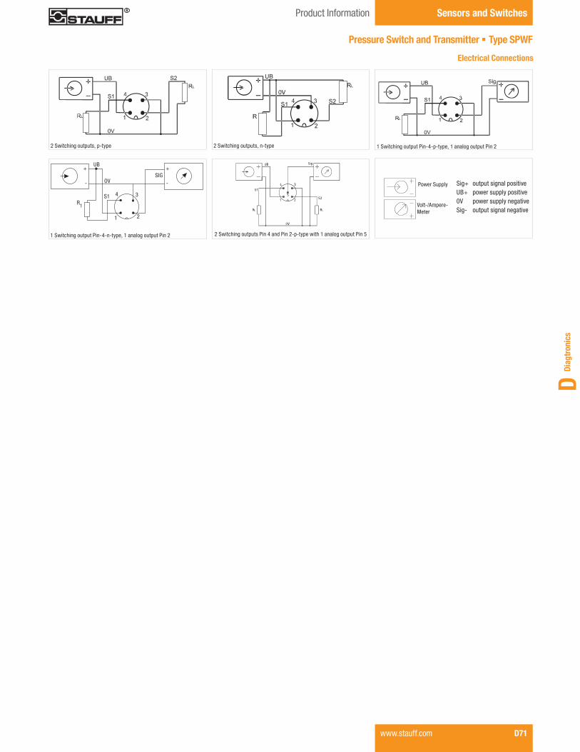
Diag
tron
ics
D
Pressure Switch and Transmitter § Type SPWF
2 Switching outputs, p-type 2 Switching outputs, n-type 1 Switching output Pin-4-p-type, 1 analog output Pin 2
1 Switching output Pin-4-n-type, 1 analog output Pin 2 2 Switching outputs Pin 4 and Pin 2-p-type with 1 analog output Pin 5
Electrical Connections
Power Supply
Volt-/Ampere-Meter
Sig+ output signal positiveUB+ power supply positive0V power supply negativeSig- output signal negative
UB
OV
+ +
- -
R1
S1
1 2
34
SIG
Product Information Sensors and Switches
www.stauff.com D71
NoAm Version Diagtronics January 2013.indd 71 22.01.2013 11:53:37

Product Description
The STWE Temperature Switch and Transmitter features LED display to provide continuous temperature monitoring and al-lows the operator to easily adjust set and reset points by using the two programming buttons located on the display face on the unit. The display face can be rotated up to 330° to offer the best possible viewing position in any application.
Features
§ Stainless Steel construction § LED display and easy programming of set points § Two switching outputs § Temperature range: -50 °C ... +125 °C / -58 °F ... +257 °F § G1/4 and 1/4 NPT process connections § Different stem lengths § LED display rotates up to 330°
Options
§ G1/2 and 1/2 NPT available process connections § Temperature range available from -200 °C ... +600 °C / -328 °F ... +1112 °F
§ One switching output and one analog output
STWE - CN0125 - N04 - 1 - 100
d Signal Output Two switching outputs (standard option) 1 One switching output, one 4 ... 20 mA Output 2
eStem Lengths 50 mm / 1.97 in 50 75 mm / 2.95 in 75 100 mm / 3.94 in 100 160 mm / 6.30 in 160 200 mm / 7.87 in 200 300 mm / 11.81 in 300
a Series and Type Temperature Switch and Transmitter STWE
b Temperature Ranges -50 ... +125 °C / -58 ... +257 °F (standard option) CN0125 -50 ... +200 °C / -58 ... +392 °F CN0200 -200 ... +600 °C / -328 ... +1112 °F CN0600 0 ... +400 °C / +32 ... +752 °F C0400 0 ... +600 °C / +32 ... +1112 °F (standard option) C0600
c Process Connection G1/4 B04 G1/2 B08 1/4 NPT (standard option) N04 1/2 NPT N08
Temperature Switch and Transmitter § Type STWE
Order Codes
Sensors and Switches Product Information / Order Codes
D72 www.stauff.com
NoAm Version Diagtronics January 2013.indd 72 22.01.2013 11:53:39

Diag
tron
ics
D
Electrical Connections
1 Switching output (Pin 4) with 1 analog output (Pin 2) (p-switching)
2 Switching output (p-switching) (Pin 4 switch 1; Pin 2 switch 2)
102
(4.0
1)St
em L
engt
h
M 1
2
65,5
0(2
.58)
30(1.18)
Ø 27(1.06)
Ø 35(1.38)
Ø 6(.24)
Temperature Switch and Transmitter § Type STWE
Technical Data
Materials § Housing: Stainless Steel § Process connection: Stainless Steel
Supply Voltage § 12...30 V DC, protection from reverse polarity and overload
Power Consumption § ≤50 mA, without load current
Switching Outputs § Switching function: Normally open (NO) or normally closed (NC)
§ Power rating: 100 mA per switch output
Adjustment § Setpoint 0.1 ° steps within temperature range § Resetpoint 0.1 ° steps within temperature range up to (Setpoint -0.1°)
Analog Output § Signal 4 ... 20 mA, 3-wire § Load resistance Ra=Us-7 V / 0.022 A
Accuracy § Accuracy of PT100 sensing element ±0.1 % of temperature range
Repeatabilty § 0.05 %
Stem Length and Working Pressure (standard option) § Ø 6 x 50 mm / .24 x 1.97 in stem length, up to 40 bar / 580 PSI
§ Additional stem lengths available upon request
Process Connection § G1/4, G1/2, 1/4 NPT, 1/2 NPT
Electrical Connection § M12 x 1 / 4-Pin
Permissible Temperatures § Ambient: -30 °C ... +80 °C / -22 °F ... +176 °F § Storage: -25 °C ... +70 °C / -13 °F ... +158 °F § Tk: 0,1 % of measuring range per 10K
EMC to IEC / EN 61326 § IEC 61000/4/2 ESD: B § IEC 61000/4/3 HF Radiated: A § IEC 61000/4/4 Burst: A § IEC 61000/4/5 Surge: A § IEC 61000/4/6 HF Mains Borne: A
EMC to IEC / EN 61326 § Approx 0.30 kg / .70 lbs (dependent on stem length)
Protection Rating § IP 65 protection rating: Dust tight and protected against water jets
Power Supply
Volt-/Ampere-Meter
Sig+ output signal positiveUB+ power supply positive0V power supply negativeSig- output signal negative
Product Information Sensors and Switches
www.stauff.com D73Dimensional drawings: All dimensions in mm (in).
NoAm Version Diagtronics January 2013.indd 73 22.01.2013 11:53:39

Temperature Transmitter § Type STC
Product Description
The STC Temperature Transmitters is designed for process temperature measurement in low pressures. This unit features an all stainless steel construction up to 300 mm / 11.81 in stem length with G1/4 and 1/4 NPT process connection and a 4 ... 20 mA output. The user can select the exact temperature range they require at time of order.
Features
§ Stainless Steel construction § 4 ... 20 mA output § 0 °C ... 50 °C, 0 °C ... 100 °C and 0 °C ... 120 °C measuring ranges available
§ L-Plug DIN EN 175301-803A (DIN 43650-A) electrical connection
§ G1/4 or 1/4 NPT process connection § 50 and 100 mm stem lengths
Options
§ 0 ... 10 V available output § M12 x 1 electrical connection available § G1/2 and 1/2 NPT available process connections § 75, 160, 200 and 300 mm stem lengths available § Available with an adjustable compression ring version for variable stem length
Order Codes
d Signal Output 4 ... 20 mA (standard option) 420A 0 ... 10 V 010V
eElectrical Connection L-Plug DIN EN 175301-803A (DIN 43650-A) (standard option) 1
M12 x 1 / 4-Pin 2
f Stem Lengths 50 mm / 1.97 in (standard option) * 50 75 mm / 2.95 in * 75 100 mm / 3.94 in (standard option) 100 160 mm / 6.30 in 160 200 mm / 7.87 in 200 300 mm / 11.81 in 300
* Length only available with a fi xed thread.
g Style Fixed thread (standard option) F Adjustable compression fi tting A
STC - C0050 - N04 - 420A - 1 - 50 F
a Series and Type Temperature Transmitter STC
b Temperature Ranges 0 ... +50 °C / +32 ... +122 °F C0050 0 ... +100 °C / +32 ... +212 °F C0100 0 ... +120 °C / +32 ... +248 °F C0120 -50 ... +200 °C / -58 ... +329 °F MIN/MAX* * Specify MIN/MAX temperature range between the -50 ... +200°C / -58 ... +329 °F range. Minimum temperature difference is 30K.
Note: Please consult STAUFF for alternative temperature ranges.
c Process Connection G1/4 * B04 G1/2 * B08 1/4 NPT (standard option) N04 1/2 NPT * N08 * Threads only available with adjustable compression ring fi tting.
Sensors and Switches Product Information / Order Codes
D74 www.stauff.com
NoAm Version Diagtronics January 2013.indd 74 22.01.2013 11:53:40

Diag
tron
ics
D
max
. Ste
m L
engt
h
L
59(2
.32)
Ø 6(.24)
Adjustable Compression Fitting M12 x 1 / 4-PinL-Plug DIN 175301-803A (DIN 43650-A)
Stem
Len
gth
70(2
.76)
59(2
.32)
87(3
.43)
Stem
Len
gth
Wiring Scheme
Adjustablecompression fitting
SW 27(Hex 1.06)
SW 27(Hex 1.06)
M12x1, 4-Pin
Temperature Transmitter § Type STC
Technical Data
Materials § Housing: Stainless Steel 1.4571 (316 Ti) § Process connection: Stainless Steel 1.4571 (316 Ti) § Stem: Stainless Steel 1.4571 (316 Ti)
Signal Outputs and Supply Voltage § 4 ... 20 mA, 2-wire, 10 ... 30 V DC, ripple <10%
§ 0 ... 10 V, 3-wire, 12 ... 30 V DC, ripple <10%
Error Signals § 23 mA sensor burnout § 3.3 mA sensor short circuit
Accuracy § ≤ ±5 % of FS*
Temperature Range § -50 °C ... +200 °C / -58 °F ... +392 °F
Measuring Range § Minimum range: 50 K § Maximum range: 250 K
Process Connection § G1/4, G1/2, 1/4 NPT, 1/2 NPT
Electrical Connection § L-Plug according to DIN EN 175301-803A (DIN 43650-A) § M12 x 1 / 4-Pin
Stem Length and Pressure Ranges § 50 ... 500 mm / 1.97 x 19.67 in: up to 40 bar / 580 PSI (Pressure ranges refer to static pressure.)
Permissible Temperatures § Ambient: max. +85 °C / +185 °F § Storage: -40 °C ... +85 °C / -40 °F ... +185 °F
EMC-Resistance § Emitted interference acc. to DIN EN 61326 § Breakdown effect acc. to DIN EN 61326
Weight § Approx. 0.14 kg / .31 Ibs (dependant on stem length)
Protection Rating § L-Plug connection: IP 65 protection rating: Dust tight and protected against water jets
§ M12 x 1 connection: IP 67 protection rating: Dust tight and protected against powerful water jets; even immersion (up to 1 m / 3.28 ft) in water is possible under defined conditions of pressure and time
Product Information Sensors and Switches
www.stauff.com D75*FS = Full ScaleDimensional drawings: All dimensions in mm (in).
3
2
3
2
11
UB+/Sig+ UB+/Sig+
Sig+
OV/Sig-OV/Sig-
DIN EN 175301-803A / 2-wire (4 ... 20 mA)
DIN EN 175301-803A/ 3-wire (0 ... 10 V)
+
-
43
2 1
3
12
4
M12 x 1 / 2-wire 4 ... 20 mA
UB+/Sig+ UB+/Sig+
OV/Sig- OV/Sig-
Sig+
M12 x 1 / 3-wire 0 ... 10 V
NoAm Version Diagtronics January 2013.indd 75 22.01.2013 11:53:41
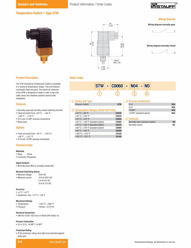
Temperature Switch § Type STW
Product Description The STW mechanical Temperature Switch is available in a variety of temperature ranges. This unit features a bimetallic fixed set point. The electrical connector of the SPW is designed to rotate in order to face the cable clamp into whatever position desired after installation.
Features
§ Normally open and normally closed switching function § Fixed set points from +60 °C ... +80 °C / +140 °F ... +176 °F
§ G1/4 and 1/4 NPT process connections § Brass body
Options
§ Fixed set points from +30 °C ... +105 °C / +86 °F ... +221 °F
§ G1/2 and 1/8 NPT process connections
Technical Data
Materials § Body: Brass § Connector: Polyamide
Signal Outputs § Normally open (NO) or normally closed (NC)
Maximal Switching Values § Maximal voltage: 250 V AC § Maximal current: 10 A at 240 V AC 5 A at 24 V AC 10 A at 12 V AC
Accuracy § ±5 °C / ±9 °F § Hysteresis: max. +15 °C / +59 °F
Maximum Ratings § Temperature: +130 °C / +266 °F § Pressure: 150 bar / 2175 PSI
Electrical Connection § DIN EN 175301-803 form A-PG09 (DIN 43650-A)
Process Connection § G1/4, G1/2, 1/8 NPT, 1/4 NPT
Protection Rating § IP 65 protection rating: Dust tight and protected against water jets
60(2
.36)
49,2
5(1
.94)
36(1.42)
SW 30(Hex 1.18)
STW - C0060 - N04 - NO
c Process Connection G1/4 B04 G1/2 B08 1/8 NPT N02 1/4 NPT (standard option) N04
d Contacts Normally open (standard option) NO Normally closed NC
Order Codes
Ø 26(1.02)
a Series and Type Pressure Switch STW
b Temperature Ranges (Fixed Set Point) +30 °C / +86 °F C0030 +40 °C / +104 °F C0040 +50 °C / +122 °F C0050 +60 °C / +140 °F (standard option) C0060 +70 °C / +158 °F (standard option) C0070 +80 °C / +176 °F (standard option) C0080 +90 °C / +194 °F C0090 +100 °C / +212 °F C0100 +105 °C / +221 °F C0105
Wiring Scheme
1
1 2
2
Wiring diagram normally open
Wiring diagram normally closed
D76 www.stauff.com Dimensional drawings: All dimensions in mm (in).
Sensors and Switches Product Information / Order Codes
NoAm Version Diagtronics January 2013.indd 76 22.01.2013 11:53:45

Diag
tron
ics
D
Flowtell Inline Flow Meter § Type SFF
Product Description The STAUFF Flowtell Inline Flow Meter is ideal for monitor case drain flows, pump performance and media flows through hydraulic circuits and sub-circuits. It allows the designer to in-stall it in any orientation (horizontal, vertical or inverted ) and is weather-tight for use outdoors and/or on systems where wash downs are required. It is also a reliable service tool that provides years of maintenance-free performance. Flows can be measured up to a value of 283 l/min / 75 GPM.
Features
§ G1/2, G3/4, G1-1/4, 1/2 NPT, 3/4 NPT and 1-1/4 NPT process connection
§ Flow ranges up to 283 l/min / 75 US GPM
Options
§ Other process connection on request
Technical Data
Materials § Aluminium end caps § Polycarbonate Windows Tube § NBR (Buna-N®) and Teflon sealings § Suitable for Mineral-Based Hydraulic Fluid
Accuracy § ±2.5 % of full scale in mid-third of flow range § ±4.0 % over entire flow range
Repeatability § ±1 % of full sale
Max. Operating Pressure § 240 bar / 3500 PSI
Max. Operating Temperature § +116 °C / +240 °F
Codes A (mm/in) B (mm/in)
SFF-L00005-B0848 1671.88 6.56
SFF-L00030-B0960 1822.38 7.16
SFF-L00075-B2090 2583.5 10.13
SFF-L00005-N0848 1671.88 6.56
SFF-L00030-N0960 1822.38 7.16
SFF-L00075-N2090 2583.5 10.13
A B
Order Codes
SFF - L00005 - N08
c Process Connection G1/2 (only L00005) B08 G3/4 (only L00030) B09 G1-1/4 (only L00075) B20 1/2 NPT (only L00005) (standard option) N08 3/4 NPT (only L00030) (standard option) N09 1-1/4 NPT (only L00075) (standard option) N20
a Series and Type Flowtell Inline Flow Meter SFF
b Flow Ranges 2 ... 18 l/min / 0.5 ... 5 US GPM L00005 12 ... 113 l/min / 3 ... 30 US GPM L00030 31 ... 283 l/min / 8 ... 75 US GPM L00075
Dimensions
Product Information / Order Codes Sensors and Switches
www.stauff.com D77Dimensional drawings: All dimensions in mm (in).
NoAm Version Diagtronics January 2013.indd 77 22.01.2013 11:53:49

D78 www.stauff.comDimensional drawings: All dimensions in mm (in).
*FS = Full Scale
Sensors and Switches Product Information / Order Codes
Flow Indicator § Types SDM / SDMKR
Product Description
Analogue fl ow indicators for measuring the fl ow rate of fl uids in mobile and industrial hydraulics. The SDMKR is designed with a loading valve for the strain test of the hydraulic system to facilitate precise control of the operating pressure. In addition, this product can also be subjected to a reverse fl ow direction (without fl ow rate determination).
Features
§ Suitable for Mineral Oil (Aluminium), HFC Fluids and Water (Brass)
§ Designed for in-line installation § Mechanical fl ow measurement § Controlling working pressure with a pressure control valve (only SDMKR)
§ Flow indication in l/min and GPM for Aluminium units, Brass units have fl ow indication for Water and Oil both in l/min
§ Aluminium unit: Dual scale § Brass unit: Single scale § Thread to connect with pressure gauge (only SDM)
Technical Data
Accuracy(at a kinematic viscosity of 28cSt):
§ Flow: ±4 % FSD § Temperature: ±2,5 °C / ±5 °F § Pressure (only SDMKR): ±1.6 % FS* § Temp. measuring range: +20 °C ... +110 °C / +55 °F ... +245 °F
§ Media temperaturepermanent: +80 °C / +176 °Ftemporary (<10 min.): +110 °C / +245 °F
Note: Other thread versions available on request.
SDM - 750 - A - 016 - T
Order Codes
70
38,6
74
Inlet and outlet both G3/4
49
30
30
78
146
130
8
ø9 (2
x)
68
67
37
18,518
7
Thread for pressure gauge G1/4
(5.12) (.28)
(.3
1)
(5.75)
(1.4
6)
(2.6
4)
(2.28) (.71) (.73)
(.35)
(1.1
8)
(3.07)
(2.7
6)
(1.18)
(1.93)
(1.5
2)
(2.9
1)
d Flow Ranges See table on page D79
eThermometer With integrated thermometer (standard option) T
a Series and Type Flow Indicator Type SDM SDM Flow Indicator Type SDMKR SDMKR
b Size 750 750 1500 (only SDM) 1500
c Housing Material Aluminium A Brass (only SDM) B
Dimensions SDM-750
Functional Principal Flow Measuring
The fl ow indicators SDM and SDMKR have a sharp-edged orifi ce and a tapered metering piston, which moves in proportion to changes of fl ow against a spring. In no fl ow condition the piston closes the opening and the pointer indicates zero.
With increasing fl ow and differential pressure the piston moves against the calibrated spring. The piston movement is directly proportional to the fl ow rate and is magnetically coupled to the rotary pointer. During this function the sharp-edged orifi ce minimises the effects of viscosity. The fl ow is shown on a calibrated scale in l/min and gal/min.
N S
S N
Controlling Working Pressure with SDMKR
The pressure control valve of the SDMKR is directly connected to a fl ow-block and together with the integrated pressure gauge it allows an exact control of the working pressure in the maximum range.For protection the SDMKR has two rupture disks. At a pressure >420 bar the disks burst and the fl uid is by-passed around the valve. The rupture disks (other pressure ranges on request) can be replaced easily.The SDMKR also permits fl ow in the reverse direction (without fl ow rate determination).
NoAm Version Diagtronics January 2013.indd 78 22.01.2013 11:53:53

Diag
tron
ics
D
Product Information Sensors and Switches
* The Brass units have a scale for water and oil – in l/min.Dimensional drawings: All dimensions in mm (in). www.stauff.com D79
30
87
199
180
40 20
65
11
43,5
Mounting holes (4x)
3/8 UNC,14 mm (.55 in) deep
73
10
53
85
Inlet and outlet both G1-1/2
74
43
70
Thread for pressure gauge G1/4
(7.09)
(7.83)
(.39)
(.43)
(2.5
6)
(1.57) (.79)
(1.7
1)
(3.43)
(2.7
6)
(2.91)
(1.69)
(2.0
9)
(3.4
5)
(1.1
8)
(2.87)
Technical Data
Flow Curves - Aluminium Version (Oil)
0.0
0.2
0.4
0.6
0.8
1.0
0 10 20 30 40 50 60
SDM 750-016
Q(l/min)
SDM 750-030
SDM 750-060
0.0
2.0
4.0
6.0
8.0
0 30 60 90 120 150 180
Q(l/min)
SDM 750-180
SDM 750-120
0.0
0.4
0.8
1.2
1.6
0 40 80 120 160 240 280200
p(bar)
Q(l/min)
SDM 1500-300
SDM 1500-200
Dimensions SDM-1500 Dimensions SDMKR-750
1,0
0,8
0,6
0,4
0,2
0,0
Δp
in b
arΔ
p in
PSI
14.5
11.6
8.7
5.8
2.9
0.0
Δp
in b
ar
Δp
in P
SI
116
87
58
29
0.0
8,0
6,0
4,0
2,0
0.0
0 10 20 30 40 50 60 Q in l/min0 3 5.5 8 10.5 13 16 Q in US GPM
0 30 60 90 120 150 180 Q in l/min0 8 16 23.4 31.2 39 46.8 Q in US GPM
Δp
in b
ar
Δp
in P
SI
1,6
1,2
0,8
0,4
0.00 40 80 120 160 200 240 280 Q in l/min0 10.5 20.8 31.2 41.6 52 62.4 72.8 Q in US GPM
23.2
17.4
11.6
5.8
0.0
Δp
in b
ar
Δp
in P
SI
4,0
3,0
2,0
1,0
0,00 100 200 300 400 Q in l/min
0 26 52 78 104Q in US GPM
58
44
29
14,5
0,0
Order Codes Max. Working Pressure (bar/PSI)
Flow Range (l/min/US GPM)Aluminum Units
Flow RangeBrass Units (only SDM) *
Weight (kg/lbs)
ConnectionT
SDM-750-A-016-T420 2 - 16 - 1,36
G3/46091 0.5 - 4 - 3.0
SDM-750-A-030-T420 2 - 30 - 1,36
G3/46091 0.5 - 8 - 3.0
SDM-750-A-060-T420 2 - 60 - 1,36
G3/46091 0.5 - 16 - 3.0
SDM-750-A-120-T420 4 - 120 - 1,36
G3/46091 1 - 32 - 3.0
SDM-750-A-180-T420 10 - 180 - 1,36
G3/46091 4 - 48 - 3.0
SDM-750-B-030-T420 - 2 - 30 l/min in oil 3,80
G3/46091 - 2- 30 l/min in water 8.40
SDM-750-B-060-T420 - 3 - 60 l/min in oil 3,80
G3/46091 - 3 - 70 l/min in water 8.40
SDM-750-B-120-T420 - 4 - 120 l/min in oil 3,80
G3/46091 - 4 - 140 l/min in water 8.40
SDM-1500-A-200-T350 10 - 200 - 3,0
G1-1/25075 5 - 50 - 6.61
SDM-1500-A-300-T350 20 - 300 - 3,0
G1-1/25075 4 - 80 - 6.61
SDM-1500-A-400-T350 20 - 400 - 3,0
G1-1/25075 5 - 100 - 6.61
SDM-1500-B-200-T350 - 10 - 200 l/min in oil 8,0
G1-1/25075 - 10 - 200 l/min in water 17.64
SDM-1500-B-400-T350 - 20 - 400 l/min in oil 8,0
G1-1/25075 - 20 - 400 l/min in water 17.64
SDMKR-750-A-030-T420 2 - 30 - 6,6
G3/46091 0.5 - 8 - 14.55
SDMKR-750-A-060-T420 5 - 60 - 6,6
G3/46091 1.3 - 16 - 14.55
SDMKR-750-A-120-T420 5 - 120 - 6,6
G16091 1.3 - 32 - 14.55
SDMKR-750-A-200-T420 10 - 200 - 6,6
G16091 4 - 53 - 14.55
(Curves reffer to kinematic viscosity of 25cSt):
SDM 1500-400
Flow Curves - Brass Version (Water)
0.0
1
1.5
0 20 40 60 80 120 140100
0.5
2
2.5
3 SDM-750-120
SDM-750-060
SDM-750-030
0.0
7.25
14.5
21.8
29
36.3
43.5
0 5.5 10.5 16 20.8 26 31.2 37
Δp in barΔp in PSI
Q in l/minQ in US GPM
0.0
1
1.5
0 50 100 150 200 300 350250
0.5
2
2.5
3SDM-1500-400
400
SDM-1500-200
0 13 26 3939 52 66 78 92.5 104
0.0
14.5
21.8
7.25
29
36.3
43.5Δp in bar
Δp in PSI
Q in l/minQ in US GPM
T
329(12.95)
53 27,5
(2.0
9)
(1.0
8)
T
160
(6.3
0)
SW41(Hex41)SW41
(Hex41)
124,
5(4
.90)
47,5
(1.8
7)
47,5
(1.8
7)
View shown without cover
Flow Indicators § Types SDM / SDMKR
NoAm Version Diagtronics January 2013.indd 79 22.01.2013 11:53:54

Sensors and Switches Overview
Flow Monitoring System § Type SGF
D80 www.stauff.com
Product Description
With the SGF fl ow monitoring system STAUFF offers two different solutions for high accuracy and high pressure fl ow monitoring.
The SFG monitoring system can be integrated into manifolds or supplied with two typs of mounting plates.
Please see page D81 for details.
Mounting Plates § Types SGFM
The connection plate SGFM is available in two versions.
§ Side port version § Bottom port version
They are only to be used with the SGF.
Please see page D84 for details.
Side Port Bottom Port
Flow Monitoring System § Type SGFE
Product Description
The SGFE Aluminum Ecofl ow Flow Meter based on the same measuring principal like the SGF, but is the economical alternative.This product only featured side port connection.
Please see page D86 for details.
Flow Rate Displays § Types STD 1 / STD 2 / STD 3 / STD 4
Product Description
The Flow Rate Display allows to visualize the values of both fl ow monitoring systems (SGF and SGFE).
STAUFF offers four versions of fl ow rate displays.
Please see page D89 for details.
STD 1 STD 2 STD 4STD 3
NoAm Version Diagtronics January 2013.indd 80 22.01.2013 11:54:03

Diag
tron
ics
D
Product Information / Order Codes Sensors and Switches
Flow Monitoring System § Type SGF
Order Codes
SGF - 0.04 - C - 1 - V - X
d Bearing Type Ball bearing 1 Spindle - bearing 2
* Special bearing typ for special application on request
eSealings FPM (Viton®) (standard option) V NBR (Buna-N®) B PTFE T EPDM E
f Special Options Contact STAUFF for details
Note: Connection Plate see page D82.
a Series and Type Flow Monitoring System SGF
b Version 0,002 ... 2 l/min / 0.0005 ... 0.53 US GPM 0.02 0,004 ... 4 l/min / 0.0011 ... 1.06 US GPM 0.04 0,01 ... 10 l/min / 0.0026 ... 2.64 US GPM 0.1 0,02 ... 18 l/min / 0.0053 ... 4.76 US GPM 0.2 0,03 ... 40 l/min / 0.0079 ... 10.57 US GPM 0.4 0,05 ... 80 l/min / 0.0132 ... 21.13 US GPM 1 0,1 ... 120 l/min / 0.0264 ... 31.70 US GPM 2 1,0 ... 250 l/min / 0.2642 ... 66.00 US GPM 4
c Material Cast Iron C Stainless Steel 1.4305 S
Available RangesVersion Geometric Tooth Volume cm3 Measuring Range (l/min/US GPM) K-Factor (Imp/Liter/Imp/Gal)
0.02 0,020,002 ... 2 500000.005 ... 0.53 189272
0.04 0,040,004 ... 4 250000.0011 ... 1.06 94636
0.1 0,10,01 ... 10 100000.0026 ... 2.64 37854.4
0.2 0,20,02 ... 18 50000.0053 ... 4.76 18927.2
0.4 0,40,03 ... 40 25000.0079 ... 10.57 9463.6
1 10,05 ... 80 10000.0132 ... 21.13 3785.44
2 20,1 ... 120 5000.0264 ... 31.70 1892.72
4 41 ... 250 2500.2642 ... 66.00 946.36
Product Description
The STAUFF SGF positive displacement Flow Meter offers a comprehensive solution for high accuracy and high pressure flow monitoring. The units are available for flow ranges from 0,002 l/min to 250 l/min / 0.0005 to 66.00 US GPM and are suitable for pressures up to 450 bar / 6500 PSI. It is possible to integrate the units direct into the hydraulic circuit. Furthermore a special digital display to visualize the flow is available.
Media specific models are available for applications such as: Hydraulic test stand, Grease, Ink, Lubrication Systems, Diesel Fuel, Kerosene and Brake Fluid.
Technical Data
Materials § Body: EN-GJS-400-15 (EN 1563) / Stainless Steel 1.4305
§ Bearings: Ball, Spindle § Sealings: FPM (Viton®), NBR (Buna-N®), PTFE, EPDM
Accuracy § ± 0.3 % of measured value at 20 cSt
Repeatability § ± 0.05 % of measured value at 20 cSt
Power Supply § 10 ... 28 V DC
Max. Operating Pressure § Cast Iron housing: 315 bar / 4568 PSI § Stainless Steel housing: 450 bar / 6526 PSI
Medium Temperature § -40 °C ... +120 °C / -40 °F ... +248 °F
Viscosity Range § Up to 100000 cSt (depends on type)
www.stauff.com D81
NoAm Version Diagtronics January 2013.indd 81 22.01.2013 11:54:04

Sensors and Switches Dimensions
Flow Monitoring System § Type SGF
Grounding
Ø6(Ø.24)
D
EK
C
H
Cast Iron Version - Housing curve mill cuted
D82 www.stauff.com
Dimensions
Version A B C D E ØG H K L M N O-Ring Weight (kg/lbs)(mm/in) (mm/in) (mm/in) (mm/in) (mm/in) (mm/in) (mm/in) (mm/in) (mm/in) (mm/in) Cast Iron * Stainless Steel **
0.02100,0 80,0 91,0
M612,5 9 114,0 58,0 70,0 40,0 20,0
11 x 22,8 3,4
3.94 3.15 3.58 .49 .35 4.49 2.28 2.76 1.57 .79 6.17 7.50
0.04100,0 80,0 91,5
M611,5 9 114,5 58,5 70,0 40,0 20,0
11 x 22,8 3,4
3.94 3.15 3.60 .45 .35 4.51 2.30 2.76 1.57 .79 6.17 7.50
0.1100,0 80,0 94,0
M69,0 9 117,0 61,0 70,0 40,0 20,0
11 x 22,8 3,4
3.94 3.15 3.70 .35 .35 4.61 2.40 2.76 1.57 .79 6.17 7.50
0.2100,0 80,0 93,5
M69,5 9 116,5 60,5 70,0 40,0 20,0
11 x 23,0 3,7
3.94 3.15 3.68 .37 .35 4.59 2.38 2.76 1.57 .79 6.61 8.16
0.4115,0 90,0 96,5
M811,5 16 119,5 63,5 80,0 38,0 34,0
17,96 x 2,624,0 5,0
4.53 3.54 3.80 .45 .63 4.70 2.50 3.15 1.50 1.34 8.82 11.02
1130,0 100,0 101,0
M812,0 16 124,0 68,0 84,0 72,0 34,0
17,96 x 2,625,3 6,8
5.12 3.94 3.98 .47 .63 4.88 2.68 3.31 2.83 1.34 11.68 15.00
2130,0 100,0 118,0
M815,0 16 141,0 85,0 84,0 72,0 34,0
17,96 x 2,626,7 8,4
5.12 3.94 4.65 .59 .63 5.55 3.35 3.31 2.83 1.34 14.78 18.52
4180,0 140,0 143,0
M1220,0 30 166,0 110,0 46,0 95,0 45,0
17,96 x 2,6214,7 18,4
7.09 5.51 5.63 .79 1.18 6.54 4.33 1.81 3.74 1.77 32.41 40,57
* Cast Iron EN-GJS-400-15 (EN 1563)** Stainless Steel 1.4305
Grounding
M12 x 1
Centre bores
B
A
Plug direction for SGF-1 / SGF-2
Grounding
Plug direction for SGF-0,02 to SGF-0,4 and SGF-4
M12
x 1
Centre bores
X
Connection Drawing (View X)
Stainless Steel Version - Housing not mill cuted
A
Cast Iron Version
LO-Ring
M N
Dimensional drawings: All dimensions in mm (in).
ØG
NoAm Version Diagtronics January 2013.indd 82 22.01.2013 11:54:06

Diag
tron
ics
D
Sensors and Switches
www.stauff.com D83
Flow Curves
Flow Monitoring System § Type SGF
6
5
4
3
2
1
0
barPS
I
87
72,5
58
44
29
14.5
0
Flow
resi
stan
ce Δ
p
100 mm2/s
21 mm2/s
5 mm2/s
0 0,5 1,0 1,5 2,00 .13 .26 .40 .53
Q in l/minQ in US GPM
Flow rate
SGF-0.02
6
5
4
3
2
1
0
barPS
I
87
72,5
58
44
29
14.5
0
Flow
resi
stan
ce Δ
p
100 mm2/s
21 mm2/s
5 mm2/s
0 1 2 3 40 .26 .53 .79 1.06
Q in l/minQ in US GPM
Flow rate
SGF-0.04
6
5
4
3
2
1
0
87
72,5
58
44
29
14.5
0
Flow
resi
stan
ce Δ
p
21 mm2/s
5 mm2/s
0 1 2 3 4 5 6 7 8 9 100 .26 .53 .79 1.06 1.32 1.59 1.85 2.11 2.38 2.64
Q in l/minQ in US GPM
Flow rate
SGF-0.1
barPS
I1000 mm2/s 500 mm2/s
100 mm2/s
145
116
87
58
29
0
Flow
resi
stan
ce Δ
p
21 mm2/s
5 mm2/s
0 2 4 6 8 10 12 14 16 180 .53 1.06 1.59 2.11 2.64 3.17 3.70 4.23 4.76
Q in l/minQ in US GPM
Flow rate
SGF-0.2
barPS
I3000 mm2/s 1000 mm2/s
100 mm2/s
10
8
6
4
2
0
500 mm2/s145
116
87
58
29
0
Flow
resi
stan
ce Δ
p
21 mm2/s
5 mm2/s
0 5 10 15 20 25 30 35 400 1.32 2.64 3.96 5.28 6.60 7.93 9.25 10.57
Q in l/minQ in US GPM
Flow rate
SGF-0.4
barPS
I1000 mm2/s
100 mm2/s
10
8
6
4
2
0
500 mm2/s 145
116
87
58
29
0
Flow
resi
stan
ce Δ
p
21 mm2/s
5 mm2/s
0 10 20 30 40 50 60 70 800 2.64 5.28 7.93 10.57 13.21 15.85 18.49 21.13
Q in l/minQ in US GPM
Flow rate
SGF-1
barPS
I1000 mm2/s
100 mm2/s
10
8
6
4
2
0
500 mm2/s3000 mm2/s
145
116
87
58
29
0
Flow
resi
stan
ce Δ
p
21 mm2/s
5 mm2/s
0 25 50 75 100 125 1500 6.60 13.21 19.81 26.42 33.02 39.63
Q in l/minQ in US GPM
Flow rate
SGF-2
barPS
I1000 mm2/s 100 mm2/s10
8
6
4
2
0
500 mm2/s3000 mm2/s 203
174
145
116
87
58
29
0
Flow
resi
stan
ce Δ
p
21 mm2/s
5 mm2/s
0 50 100 150 200 250 3000 13.21 26.42 39.63 52.83 66.04 79.25
Q in l/minQ in US GPM
Flow rate
SGF-4
barPS
I1000 mm2/s 100 mm2/s14
12
10
8
6
4
2
0
500 mm2/s3000 mm2/s
NoAm Version Diagtronics January 2013.indd 83 22.01.2013 11:54:09

Sensors and Switches Connection Plates
Flow Monitoring System - Connection Plate Type SGFM for use with SGF
D84 www.stauff.com
Side Ports Bottom Ports
Flow meter
Connection plateConnection plate
Flow meter
Product Description
STAUFF offers different connections plates to connect yourSGF fl ow monitoring system to your application. They allow a side port or bottom port connection and are available in different thread sizes.
Order Codes
SGFM - 0.4 - S - C - 15 - X
a Series and Type Flow Monitoring System - Connection Plate SGFM
b SizeManifold Size Available Thread Connections Code
SGF-0.02... SGF-0.2
SAE -4, -6, -8, -12
0.2NPT1/4 NPT, 3/8 NPT, 1/2 NPT, 3/4 NPT
BSPP G1/4, G3/8, G1/2, G3/4
SGF-0.4SAE -8, -12, -16
0.4NPT 1/2 NPT, 3/4 NPT, 1 NPTBSPP G1/2, G3/4, G1
SGF-1 ... 2
SAE -8, -12, -16
1NPT1/2 NPT, 3/4 NPT, 1 NPT, 1-1/4 NPT
BSPP G1/2, G3/4, G1
SGF-4SAE -12, -16, -20
4NPT 3/4 NPT, 1 NPT, 1-1/4 NPTBSPP G3/4, G1, G1-1/4, G1-1/2
SGF-10SAE Flange 1-1/2, 2
10BSPP G1-1/2, G2
d Material Cast Iron C Stainless Steel 1.4305 S
eConnection Thread G1/4 1 G3/8 2 G1/2 3 G3/4 4 G1 5 G1-1/4 6 G1-1/2 7 1/4 NPT 8 3/8 NPT 9 1/2 NPT 10 3/4 NPT 11 1 NPT 12 1-1/4 NPT 13 1-1/2 NPT 14 -8 SAE 15 -12 SAE 16 -16 SAE 17 -20 SAE 18 -24 SAE 19 -32 SAE 20 Others on request
f Special Options Contact STAUFF for details
c Connection Type Side Port Connection S Bottom Port Connection B
NoAm Version Diagtronics January 2013.indd 84 22.01.2013 11:54:09
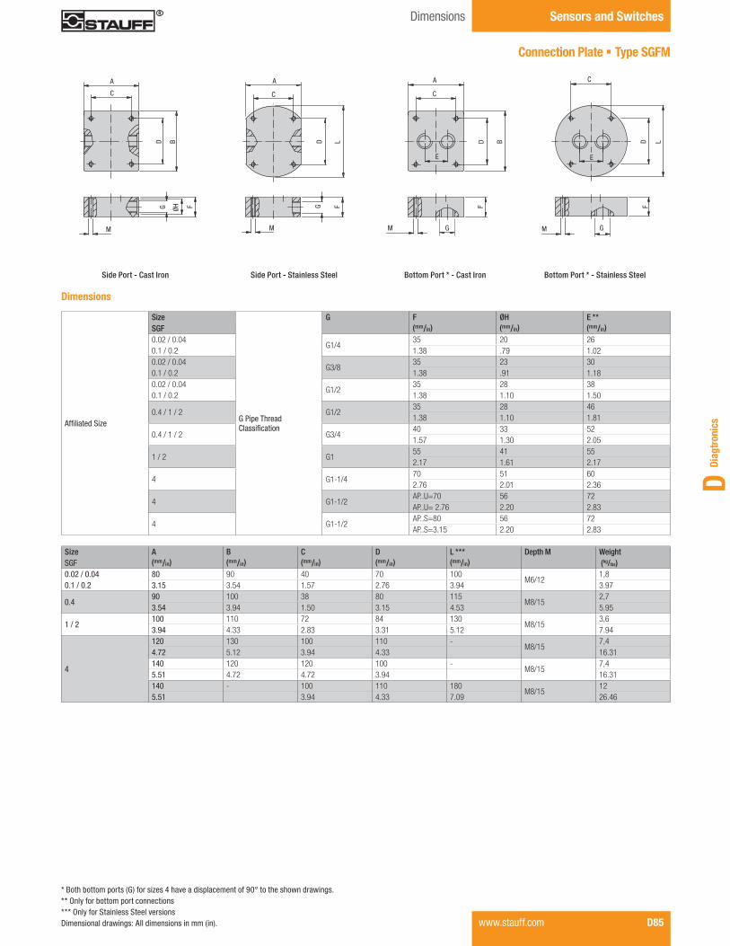
Diag
tron
ics
D
Affiliated Size
Size
G Pipe Thread Classification
G F ØH E ** SGF (mm/in) (mm/in) (mm/in)0.02 / 0.04
G1/435 20 26
0.1 / 0.2 1.38 .79 1.020.02 / 0.04
G3/835 23 30
0.1 / 0.2 1.38 .91 1.180.02 / 0.04
G1/235 28 38
0.1 / 0.2 1.38 1.10 1.50
0.4 / 1 / 2 G1/235 28 461.38 1.10 1.81
0.4 / 1 / 2 G3/440 33 521.57 1.30 2.05
1 / 2 G155 41 552.17 1.61 2.17
4 G1-1/470 51 602.76 2.01 2.36
4 G1-1/2AP..U=70 56 72AP..U= 2.76 2.20 2.83
4 G1-1/2AP..S=80 56 72AP..S=3.15 2.20 2.83
A
C
M
D BG ØH F FG
M
A
C
D L
A
C
D B
F
GM M G
FD L
E
C
E
Side Port - Cast Iron Side Port - Stainless Steel Bottom Port * - Stainless SteelBottom Port * - Cast Iron
Dimensions
* Both bottom ports (G) for sizes 4 have a displacement of 90° to the shown drawings.** Only for bottom port connections*** Only for Stainless Steel versionsDimensional drawings: All dimensions in mm (in). www.stauff.com D85
Size A B C D L *** Depth M WeightSGF (mm/in) (mm/in) (mm/in) (mm/in) (mm/in) (kg/lbs)0.02 / 0.04 80 90 40 70 100
M6/121,8
0.1 / 0.2 3.15 3.54 1.57 2.76 3.94 3.97
0.490 100 38 80 115
M8/152,7
3.54 3.94 1.50 3.15 4.53 5.95
1 / 2100 110 72 84 130
M8/153,6
3.94 4.33 2.83 3.31 5.12 7.94
4
120 130 100 110 -M8/15
7,44.72 5.12 3.94 4.33 16.31140 120 120 100 -
M8/157,4
5.51 4.72 4.72 3.94 16.31140 - 100 110 180
M8/1512
5.51 3.94 4.33 7.09 26.46
Sensors and SwitchesDimensions
Connection Plate § Type SGFM
NoAm Version Diagtronics January 2013.indd 85 22.01.2013 11:54:10

Sensors and Switches Product Information / Order Codes
D86 www.stauff.com
Flow Monitoring System § Type SGFE
Product Description Based upon the same positive displacement gear principle as the STAUFF SGF series, the SGFE Aluminum Ecoflow Flow Meter is an economical alternative for applications that require lower accuracy, temperature, and pressure.
Features
§ In-line connection on the side § An integrated pick up with PNP or NPN switching output produces one impulse per tooth volume.
Options
§ LCD flow display with analog output and set limit switches mounted directly to the flow meter
Technical Data
Materials § Body: Aluminium § Bearings: Stainless Steel, Bronze, DU § Sealings: FPM (Viton®), NBR (Buna-N®), PTFE, EPDM
Accuracy § ± 2 % of measured value at 20 cSt
Power Supply § 10 ... 30 V DC
Max. Operating Pressure § 200 bar / 2900 PSI
Medium Temperature § 0 °C ... +80 °C / 32 °F ... +176 °F
Viscosity Range § Up to 100000 cSt (depends on type)
Order Codes
SGFE - 0.04 - S - 1 - N - V - X
a Series and Type Flow Monitoring System SGFE
b Version 0,05 ... 4 l/min / 0.013 ... 1.06 US GPM 0.04 0,1 ... 10 l/min / 0.026 ... 2.64 US GPM 0.1 0,2 ... 30 l/min / 0.053 ... 7.93 US GPM 0.4 0,5 ... 70 l/min / 0.132 ... 18.49 US GPM 2 3,0 ... 150 l/min / 0.79 ... 39.63 US GPM 4
c Connection Type Connection plate and location on side S
d Bearing Type Stainless Steel - ball bearing 1 Bronze - sleeve bearing 2 DU - sleeve bearing 3
ePulse Output NPN N PNP P
fSealings FPM (Viton®) (standard option) V NBR (Buna-N®) B PTFE T EPDM E
g Special Options Contact STAUFF for details
NoAm Version Diagtronics January 2013.indd 86 22.01.2013 11:54:11

Diag
tron
ics
D
Dimensions Sensors and Switches
www.stauff.com D87Dimensional drawings: All dimensions in mm (in).
Flow Monitoring System § Type SGFE
SGFE-0.04
Ø21
G1/4
66
M6
PG 9
13
12
48
95
(2.60)
(.51) (.4
7)
(1.8
9)
(3.7
4)
(Ø.83)
60(2
.36)
80(3.15)
66
PG 9
(2.60)
14 (.55)
M6
12 (.47)
50(1
.97)
97 (3.8
2)
Ø23,9(Ø.94)
G1/4
60(2
.36)
80(3.15)
SGFE-0.1 SGFE-0.4
PG 9
106
(4.1
7)
59(2
.32)
17 (.67)
Ø9(Ø.35)
Ø29(Ø1.14)
G1/2
26(1
.02)
68(2.68)110
(4.33)
SGFE-2 SGFE-4
PG 9 PG 9
Ø9(Ø.35)
25 (.98)
70 (2.7
6)11
7(4
.61)
Ø35(Ø1.38)
G3/4
26(1
.02)
68(2.68)
110(4.33)
26(1
.02)
82(3
.23)
47,5
(1.8
7)
Ø43(Ø1.69) G1
92(3.62)170
(6.69)
47,5
(1.8
7)12
0(4
.72)
30(1
.18)
97(3
.82)
144
(5.6
7)
Ø11(Ø.43)
NoAm Version Diagtronics January 2013.indd 87 22.01.2013 11:54:13

4
3
2
1
0
barPS
I
58
44
29
14.5
0
Flow
resi
stan
ce Δ
p
280 mm2/s
0 1 2 3 40 .26 .53 .79 1.06
Q in l/minQ in US GPM
Flow rate
SGFE-0.04
7
6
5
4
3
2
1
0
barPS
I
101,5
87
72,5
58
44
29
14.5
0
Flow
resi
stan
ce Δ
p
280 mm2/s
0 1 2 3 4 5 6 7 8 9 100 .26 .53 .79 1.06 1.32 1.59 1.85 2.11 2.38 2.64
Q in l/minQ in US GPM
Flow rate
SGFE-0.1
6
5
4
3
2
1
0
87
72,5
58
44
29
14.5
0
Flow
resi
stan
ce Δ
p
21 mm2/s
5 mm2/s
0 5 10 15 20 25 300 1.32 2.64 3.96 5.28 6.60 7.93
Q in l/minQ in US GPM
Flow rate
SGFE-0.4
barPS
I1000 mm2/s 280 mm2/s 100 mm2/s
Flow
resi
stan
ce Δ
p
21 mm2/s
5 mm2/s
Q in l/minQ in US GPM
Flow rate
SGFE-2
barPS
I10000 mm2/s 1000 mm2/s
100 mm2/s
280 mm2/s
Flow
resi
stan
ce Δ
p
21 mm2/s
50 mm2/s
0 5 10 15 20 25 30 35 400 1.32 2.64 3.96 5.28 6.60 7.93 9.25 10.57
Q in l/minQ in US GPM
Flow rate
SGFE-4
barPS
I
10000 mm2/s
100 mm2/s
280 mm2/s
Sensors and Switches Flow Curves
Flow Monitoring System § Type SGFE
D88 www.stauff.com
100 mm2/s 50 mm2/s
21 mm2/s
5 mm2/s
100 mm2/s
50 mm2/s
21 mm2/s5 mm2/s
50 mm2/s
Note: For trouble-free and safe operation of the flowmeters the correct selection of type and size is critical. Due to the great number of different applications and flow-meter versions the technical data in the catalogue are of general character.
Certain characteristics of the devices deoend on type, size and measuring range as well as on the medium to be measured.
For exact flowmeter select please contact STAUFF. 0 10 20 30 40 50 60 700 2.64 5.28 7.93 10.57 13.21 15.85 18.49
6
5
4
3
2
1
0
87
72,5
58
44
29
14.5
0
7
6
5
4
3
2
1
0
101,5
87
72,5
58
44
29
14.5
0
1000 mm2/s
NoAm Version Diagtronics January 2013.indd 88 22.01.2013 11:54:14
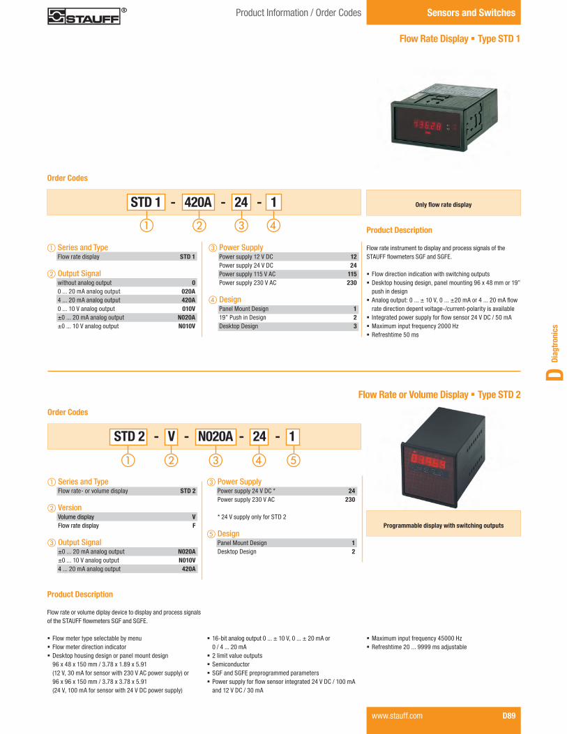
Diag
tron
ics
D
www.stauff.com D89
Product Information / Order Codes Sensors and Switches
Flow Rate Display § Type STD 1
Product Description Flow rate instrument to display and process signals of the STAUFF flowmeters SGF and SGFE.
§ Flow direction indication with switching outputs § Desktop housing design, panel mounting 96 x 48 mm or 19” push in design
§ Analog output: 0 ... ± 10 V, 0 ... ±20 mA or 4 ... 20 mA flow rate direction depent voltage-/current-polarity is available
§ Integrated power supply for flow sensor 24 V DC / 50 mA § Maximum input frequency 2000 Hz § Refreshtime 50 ms
Flow Rate or Volume Display § Type STD 2
Product Description Flow rate or volume diplay device to display and process signals of the STAUFF flowmeters SGF and SGFE.
§ Flow meter type selectable by menu § Flow meter direction indicator § Desktop housing design or panel mount design 96 x 48 x 150 mm / 3.78 x 1.89 x 5.91 (12 V, 30 mA for sensor with 230 V AC power supply) or 96 x 96 x 150 mm / 3.78 x 3.78 x 5.91 (24 V, 100 mA for sensor with 24 V DC power supply)
STD 1 - 420A - 24 - 1
Order Codes
a Series and Type Flow rate display STD 1
b Output Signal without analog output 0 0 ... 20 mA analog output 020A 4 ... 20 mA analog output 420A 0 ... 10 V analog output 010V ±0 ... 20 mA analog output N020A ±0 ... 10 V analog output N010V
c Power Supply Power supply 12 V DC 12 Power supply 24 V DC 24 Power supply 115 V AC 115 Power supply 230 V AC 230
d Design Panel Mount Design 1 19” Push in Design 2 Desktop Design 3
Order Codes
Only flow rate display
STD 2 - V - N020A - 24 - 1
Programmable display with switching outputs
c Power Supply Power supply 24 V DC * 24 Power supply 230 V AC 230
* 24 V supply only for STD 2
e Design Panel Mount Design 1 Desktop Design 2
a Series and Type Flow rate- or volume display STD 2
b Version Volume display V Flow rate display F
c Output Signal ±0 ... 20 mA analog output N020A ±0 ... 10 V analog output N010V 4 ... 20 mA analog output 420A
§ 16-bit analog output 0 ... ± 10 V, 0 ... ± 20 mA or 0 / 4 ... 20 mA
§ 2 limit value outputs § Semiconductor § SGF and SGFE preprogrammed parameters § Power supply for flow sensor integrated 24 V DC / 100 mA and 12 V DC / 30 mA
§ Maximum input frequency 45000 Hz § Refreshtime 20 ... 9999 ms adjustable
NoAm Version Diagtronics January 2013.indd 89 22.01.2013 11:54:15

Sensors and Switches Product Information / Order Codes
Flow Rate and Volume Display§ Type STD 3
D90 www.stauff.com
Product Description
Selectable fl ow rate or volume display in one device to display and process signals of the STAUFF SGF and SGFE.
§ Flow meter and volume meter type programmable § Desktop housing design or panel mount design § 12-bit analog output 0 ... 10 V, 0 ... 20 mA or 4 ... 20 mA § Switching outputs available § Power supply for fl ow sensor integrated 12 V / 100 mA § Maximum input frequency 6000 Hz § Refreshtime 100 ... 9999 ms § Power supply 24 V (11-36 V DC) or 110 / 230 V (85-250 V AC)
Order Codes
c Power Supply Power supply 24 V DC (11-36 V DC) 24VDC Power supply 110/230 V AC (85-2501 V AC) 230VAC
a Series and Type Flow rate- and volume display STD 3
b Output Signal Without O 0 ... 10 V 010V 0 ... 20 mA 020A 4 ... 20 mA 420A
Programmable display with switching outputs STD 3 - N020A - 24 - O - 1
d Switching Output Without switching output O With switching output W
e Design Panel Mount Design 1 Desktop Design 2
Signal Converter § Type STD 4
Product Description
STD 4 is a small and inexpensive, but very powerful converter for industrial applications where frequencies of the fl owmeters SGF or SGFE will be converted into an analog signal or a serial data stream. The unit is housed in a compact housing for DIN rail mounting and is equipped with 12 screw terminal connec-tions and a 9-pin Sub-D socket.
§ Input frequency for scale in the range of 0.1 Hz to 1 MHz adjustable
§ Extremely fast conversion time of only 1 ms (f> 3 kHz) § Analog outputs ± 10 V, 0 ... ± 20 mA and 4 ... 20 mA § Polarity of the output signal depends on the direction of rotation
§ Converts also sum, difference, product or ratio of two frequencies
§ RS 232 and RS 485 interface for serial readout of the sensor frequency
§ Power supply 18 ... 30 V DC § Programmable digital fi lter and default option for any linearization curves
§ Maximum frequency 1 MHz (200 kHz with SGF / SGFE § Can also handle asymmetric TTL pulse
Order Code
STD 4
NoAm Version Diagtronics January 2013.indd 90 22.01.2013 11:54:17

Diag
tron
ics
D
www.stauff.com D91
Notes
NoAm Version Diagtronics January 2013.indd 91 22.01.2013 11:54:17