Embed Size (px)
Citation preview

Nokia F-Bus Protocol
Chapter - III
NOKIA F-BUS PROTOCOL
3.1 INTRODUCTION TO NOKIA F-BUS
Most Nokia phones have F-Bus and M-Bus connections that can be used
to connect a phone to a PC or in our case a microcontroller. The connection can
be used for controlling just about all functions of the phone, as well as uploading
new firmware etc. This bus will allow us to send and receive SMS messages.
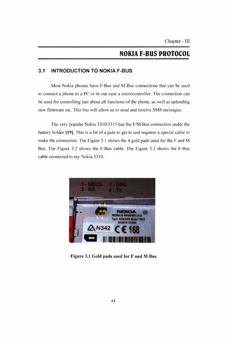
The very popular Nokia 3310/3315 has the F/M Bus connection under the
battery holder [19]. This is a bit of a pain to get to and requires a special cable to
make the connection. The Figure 3.1 shows the 4 gold pads used for the F and M
Bus. The Figure 3.2 shows the F-Bus cable. The Figure 3.3 shows the F-Bus
cable connected to my Nokia 3310.
0MOMLf PHONIt tTO Typt HHM-6NK Hc4«l lJ10
MADI M KOMA
^N342
mniiiiiHitiiiiniinRMFigure 3.1 Gold pads used for F and M Bus
44
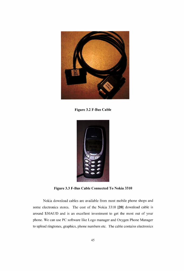
Figure 3.2 F-Bus Cable
Figure 3.3 F-Bus Cable Connected To Nokia 3310
Nokia download cables are available from most mobile phone shops and
some electronics stores. The cost of the Nokia 3310 [20] download cable is
around S30AUD and is an excellent investment to get the most out of your
phone. We can use PC software like Logo manager and Oxygen Phone Manager
to upload ringtones, graphics, phone numbers etc. The cable contains electronics
45

to level convert 3V signals to RS232 type signals. There are also M and F bus
switching in most cables.
The differences of M-Bus and F-Bus are;
M-Bus is a one pin bi-directional bus for both transmitting and receiving
data from the phone. It is slow (9600bps) and only half-duplex. Only two pins on
the phone are used. One ground and one data. M-Bus runs at 9600bps, 8 data
bits, odd parity, one stop bit. The data terminal ready (DTR) pin must be cleared
with the request to send (RTS). This powers the electronics in the cable and I
think it sets it for M-Bus operation.
F-Bus is the later high-speed full-duplex bus. It uses one pin for
transmitting data and one pin for receiving data plus the ground pin. Very much
like a standard serial port. It is fast 115,200bps, 8 data bits, no parity, one stop
bit. For F-Bus the data terminal ready (DTR) pin must be set and the request to
send (RTS) pin cleared.
3.2 THE F-BUS PROTOCOL AND COMMANDS
The F-Bus is bi-directional serial type bus running at 115,200bps, 8 data
bits. The serial cable contains electronics for level conversion and therefore
requires power. The first thing to do is supply power to the cable electronics and
this is done by setting the DTR (Data Terminal Ready) pin and clearing the RTS
(Request to Send) pin.
For all you microcontrollers connect the DTR pin to a +3 to 12 Volt
supply and RTS to a -3 to -12Volt supply. The easy way to achieve this is by
using a Max232 or similar transceiver for the RS232 TX and RX pins and then
connecting the DTR pin on the serial cable to the V+ pin on the Max232. Do the
same for the RTS; however connect it to the V- pin on the Max232. The V+ and
46

V- pins are derived from internal charge pumps that double the input voltage, i.e.
for a 5V Max232, the V+ will +10V and the V- will be -10V.
The next step is to synchronize the UART in the phone with your PC or
microcontroller. This is done by sending a string of 0x55 or 'U' 128 times. The
bus is now ready to be used for sending frames.
The Nokia protocol has a series of commands [19] that allow the user to
make calls, send and get SMS messages and lots more.
Sample frame sent to my Nokia 3310 (showed as a Hex dump)
Byte: 00 01 02 03 04 05 06 07 08 09 10 11 12 13 14 15
Data: IE 00 0C D1 00 07 00 01 00 03 00 01 60 00 72 D5
This sample frame is used to get the hardware and software version from
a Nokia phone. It is a good starting point to test if our implementation of the
protocol is working.
Byte 0: All frames sent by cable will start with the character Ox IE first.
This is the F-Bus Frame ID. Cable is OxlE and InfraRed is OxlC.
Byte 1: This is the destination address. When sending data, it's the
phone's device ID byte. In our case it's always 00 for the phone.
Byte 2: This is the source address. When sending data, it's the PC's device
ID byte. In our case it's always OxOC (Terminal).
Byte 3: This is the message type or 'command'. OxDl is Get HW & SW
version.
Byte 4 & 5: Byte 4 & 5 is the message length. In our case it is 7 bytes
long. Byte 4 is the MSB and byte 5 is the LSB.
47

Byte 6: The data segment starts here and goes for 7 bytes in our case. As
The Nokia is a 16 bit phone and therefore requires an even number of
bytes. As ours is odd the last byte will be a padding byte and the message
will end at location 13.The last byte in the data segment (Byte 12 above)
is the sequence number. The last 3 bits of this byte increments from 0 to 7
for each frame. This part needs to be sent back to the phone in the
acknowledge frame.
Bytes 14 & 15: The second to last byte is always the odd checksum byte
and the last byte is the even checksum byte. The checksum is calculated
by XORing all the odd bytes and placing the result in the odd Checksum
location and then XORing the even bytes and then placing the result in
the even byte [21].
If the phone received, it shows reply with the following data
IE OC 00 7F 00 02 D1 00 CF71
IE 0C 00 D2 00 26 01 00 00 03 56 20 30 34 2E 34 35 0A 32 31 2D
30 36 2D 30 31 0A 4E 48 4D 2D 35 0A 28 63 29 20 4E 4D
50 2E 00 01 41 3F A4
The first line is an Acknowledge command frame. Notice how the
destination and source addresses are now swapped. This is because the Nokia
phone is now talking. This message is two bytes long with the two bytes
representing the message type received (OxDl) and the sequence number (0x00).
The last two bytes are the checksum and should be checked to make sure the
data is correct. The 3310 will be waiting for an acknowledge frame after these
two frames were sent. If the acknowledge frame is not sent the 3310 will retry
sending the data. The 3310 will only send the data 3 times and then gives up.
The second frame from our Nokia 3310 is the data we requested. The
message type is 0xD2. This is 'receive Get HW&SW version'. This 38-byte
(0x26) message should show 0x0003 "V” "firmware\n" "firmware date\n"
48

"model\n" "(c) NMP." The last byte in the data is the sequence number. As with
standard F-bus frames, the last two bytes in the frame are checksum bytes.
The received data without f-bus frame
01 00 00 03 56 20 30 34 2E 34 35 OA 32 31 2D 30 36 2D 30 31
OA 4E 48 4D 2D 35 OA 28 63 29 20 4E 4D 50 2E 00 01 41
00 03 V 0 4. 4 5 \n2 1 /0 6/01 \nNHM - 5 \n(c)NM P
Sequence no. All that is required now is to send a acknowledge
frame back to the phone to say 'I got it!'
IE 00 0C 7F 00 02 D2 01 CO 7C
0x7F is the acknowledge frame's command. We are only required
to send a two-byte message so length is set to 0x02. The message
contains the acknowledged message type (0xD2) and the sequence
no. (0x01). The sequence number is made from the last 3 bits of
the sequence number in the previous frame. The checksum needs
to be calculated and sent.
3.3 SMS INTRODUCTION
The Short Message Service (SMS) allows text messages to be sent and
received to and from mobile telephones [21]. The Text can comprise words or
numbers or an alphanumeric combination. SMS was created as part of the GSM
phase 1 standard. The first short message is believed to have been sent in Dec
1992 from a PC to a mobile phone on the Vodafone GSM network in the
U.K.Each short message is upto 160 characters in length when Latin alphabets
are used, and 70 characters in length when non-Latin alphabets such as Arabic
and Chinese are used.
The Market in Europe alone had reached over three billion short messages
per month as of Dec 1999.1n the next 2 years the WAP, will continue this growth
path. Typically uses of SMS include notifying a mobile phone owner of a voice
49

mail message, alerting a salesperson of an inquiry and telling a driver the address
of the next pick up.
SMS is essentially similar to paging, but SMS messages don’t require the
mobile phone to be active and within range, as they will be held for a number of
days until the phone is active and within range. SMS messages are transmitted
within the same cell or to any one with roaming capability. They can also be sent
to the digital phones from the websites equipped with the PC link or from one
digital phone to another. As SMS gateway is a web site that acts as an
international gateway for users with roaming capability.
The SMS is a store and forward service i.e. Short messages are not send
directly from sender to recipient, but via an SMS center. Each mobile telephone
network that supports SMS has one or more messaging centers to handle and
mange the short messages.
The SMS features confirmation of message delivery i.e. the sender of the
short message can receive a written message back notifying them whether the
short message has delivered or not. Short messages can be sent and received
simultaneously with GSM voice, data and FAX calls. Ways of sending multiple
short messages are available. SMS concatenation and SMS compression have
been defined and incorporated in the GSM SMS standards.
The network operator needs to purchase its first generation SMS center as
a part of the network-commissioning plan. The initial SMS center may simply be
a voice mail platform module for a standalone SMS center. It is not possible to
make the SMS available without an SMS center since all short messages passed
through their SMS center.
50

The introduction of standardized protocols such as SIM Application tool
kit and the WAP contribute to an increase in messaging usage by providing a
standard service development and deployment environment for application
developers and business partners.
The introduction of more user-friendly terminals contributes to increase in
message usuage. Terminals such as smart phones make it easier for users to
originate, reply to other voice access messaging services through the provision
of a QWERTY keyboard, rather than the limited keypad on standard mobile
phones.
3.4 SENDING AN SMS MESSAGE
To send a SMS message with F- Bus, fist we have to know GSM 3.38-
alphabets and language-specific information [22]. This is the Technical
specification that describes the packing of 7 bit characters and shows the
standard character map. Packing ASCII into 7-bit characters is a pain, but is
quite easy to do. This is called as SMS Point-to-Point Character Packing [19].
For example let’s decode the string “hello”
First display hello in Hexadecimal using the character map
provided in GSM 3.38.For A to Z and numbers its just the standard
ASCII conversion.
hello (ASCII characters)
68 65 6C 6C 6F (In hexadecimal)
1101000 1100101 1101100 1101111 (In Binary)
When dealing with binary, it makes life easier to write everything
backwards. The first byte in the string is on the right. The least significant bit is
then displayed on the left with the most significant bit on the left. Shown below
is the same string of 'hello' just displayed backwards. Then it's just a matter to
dividing the binary values into bytes starting with the first character in the string.
51

(Start from right and go to left.) The first decoded byte is simply the first 7 bits
of the first character with the first bit of the second character added to the end as
shown below. The next decoded byte in then the remaining 6 bits from the
second character with two bits of the third byte added to the end. This process
just keeps going until all characters are decoded. The last decoded byte is the
remaining bits from the last character with the most significant bits packed with
zeros.6F 6C 6C 65 ' 68
1101111 1101100 1101100 1100101 1101000
(The ASCII characters shown in binary)
110 11111101 10011011 00110010 11101000
(The above binary just split into 8 bit segments)
06 FD 9B 32 E8
(The 8 bit segments decoded into hex)
The message hello is therefore E8 32 9B FD 06 when packed.
■ The Full SMS Message Frame
To send full SMS message frame, the GSM 3.40 technical
realization of the SMS point-to-point is used. This specification
describes the following SMS fields in detail..
Sample frame sent to my Nokia 3310 (showed as a Hex dump) 98
Bytes
Byte: 00 01 02 03 04 05 06 07 08 09 10 11 12 13 14 15 16 17 18
19 20 21 22 23 24 25 26 27 28 29 30 31 32 33 34 35
Data: IE 00 0C 02 00 59 00 01 00 01 02 00 07 91 16 14 91 09 10
F0 00 00 00 00 15 00 00 00 33 0A 81 40 30 87 00 47
SMS message centre Phone number
Byte: 36 37 38 39 40 41 42 43 44 45 46 47 48 49 50 51 52 53 54
55 56 57 58 59 60 61 62 63 64 65 66 67 68 69 70 71
52

Data: 00 00 00 00 00 A7 00 00 00 00 00 00 C8 34 28 C8 66 BB
40 54 74 7A 0E 6A 97 E7 F3 FO B9 OC BA 87 E7 AO 79 D9
Start of Message - Hi All. This message was sent through F-Bus.
Cool!!
Byte: 72 73 74 75 76 77 78 79 80 81 82 83 84 85 86 87 88 89 90
91 92 93 94 95 96 97
Data: 4D 07 D1 D1 F2 77 FD 8C 06 19 5B C2 FA DC 05 1A BE
DF EC 50 08 01 43 00 7A 52
F-Bus Frame Header
Byte 1: Destination address.
Byte 2: Source address.
Byte 3: Message Type or 'command'. 0x02 (SMS Handling).
Byte 4 & 5: Message length. In our case it is 0x0059 bytes long or
89 bytes in decimal.
(SMS) Short Message Service Frame Header
Byte 6 to 8: Start of the SMS Frame Header. 0x00, 0x01, 0x00
Byte 9 to 11: 0x01, 0x02, 0x00 = Send SMS Message
(SMSC) Short Message Service Centre (12 Bytes)
Byte 12: SMS Centre number length. 0x07 is 7 bytes long. This
includes SMSC Number Type and SMS Centre Phone Number
Byte 13: SMSC number type e.g. 0x81-unknown 0x91-
intemational Oxal-national
1XXXIIII: Where I is the Numbering-plan-identification (Refer to
GSM 03.40 - 9.1.2.5 Address fields)
1TTT XXXX: Where T is the Type-of-number (Refer to GSM
03.40 - 9.1.2.5 Address fields)
Byte 14 to 23: (Octet format) SMS Centre Phone Number In this
case +61 411990010
53
(TPDU) Transfer Protocol Data Unit
Byte 24: Message Type
XXXX XXXI = SMS Submit - The short message is transmitted
from the Mobile Station (MS) to the Service Centre (SC).
XXXX XXXO = SMS Deliver - The short message is transmitted
from the SC to the MS.
Byte 25: Message Reference if SMS Deliver & Validity Indicator
used
ID. Refer to GSM 3.40 - 9.2.3.9 TP-Protocol-Identifier (TP-PID)
Byte 27: Data Coding Scheme. Refer to GSM 03.38 & GSM 3.40 -
9.2.3.10 TP-Data-Coding-Scheme (TP-DCS)
Byte 28: Message Size is 0x33 in hex or 51 bytes long in decimal.
This is the size of the unpacked message.
Destination's Phone Number (12 Bytes)
Byte 29: Destination's number length. Is this correct?. Byte 30:
Number type e.g. 0x81-unknown 0x91-international Oxal-national
Byte 31 to 40: (Octet format) Destination's Phone Number
Validity Period (VP)
Byte 41: Validity-Period Code. Time period during which the
originator considers the short message to be valid.
Byte 42 to 47: Service Centre Time Stamp?? For SMS-Deliver
The SMS Message (SMS-SUBMIT)
Byte 48 to 92: This is the SMS message packed into 7 bit
characters. SMS Point-to-Point Character Packing
Byte 93: Always 0x00
The F-Bus usual ending
Byte 94: Packet Sequence Number
Byte 95: Padding Byte - String is old and requires to be even!
Byte 96 & 97: Odd & even checksum bytes.
54

If the phone receives a valid frame it should reply with something
like this below, to say it got the message.
Reply frame sent from my Nokia 3310 (showed as a Hex dump)
Byte: 00 01 02 03 04 05 06 07 08 09
Data: IE 0C 00 7F 00 02 02 03 1C 72
This is just like the above Acknowledge command frame. The destination
and source addresses are swapped, as this is a frame from the phone to the PC.
This message is two bytes long with the first byte representing the message type
received (0x02) and the next byte, the sequence number (0x03). The last two
bytes are the checksum and should be checked to make sure the data is correct.
After a short time the phone will reply with a 'Message sent' frame shown below.
Byte: 00 01 02 03 04 05 06 07 08 09 10 11 12 13 14 15 16 17
Data: IE 0C 00 02 00 09 01 08 00 02 64 12 00 01 44 00 3F IE
Byte 03: Message Type = 0x02 - SMS Handing
Byte 04 & 05: Message Length = 0x0009 - 9 Bytes long
Byte 09: 0x02 = Message Sent
Byte 10 to 14: Unsure of what this is?
The PC must then acknowledge the frame.
Byte: 00 01 02 03 04 05 06 07 08 09
Data: IE 00 0C 7F 00 02 02 04 10 79
3.5 RECEIVING AN SMS MESSAGE
When the phone gets sent a SMS message it sends a 'SMS Message
Received Frame' with the message attached. Then we have to do is decode it!
The SMS send example above sends a SMS message back to my phone
(The same phone sending the message). Therefore below is the SMS message
that was sent above, but now getting received by the phone.
55
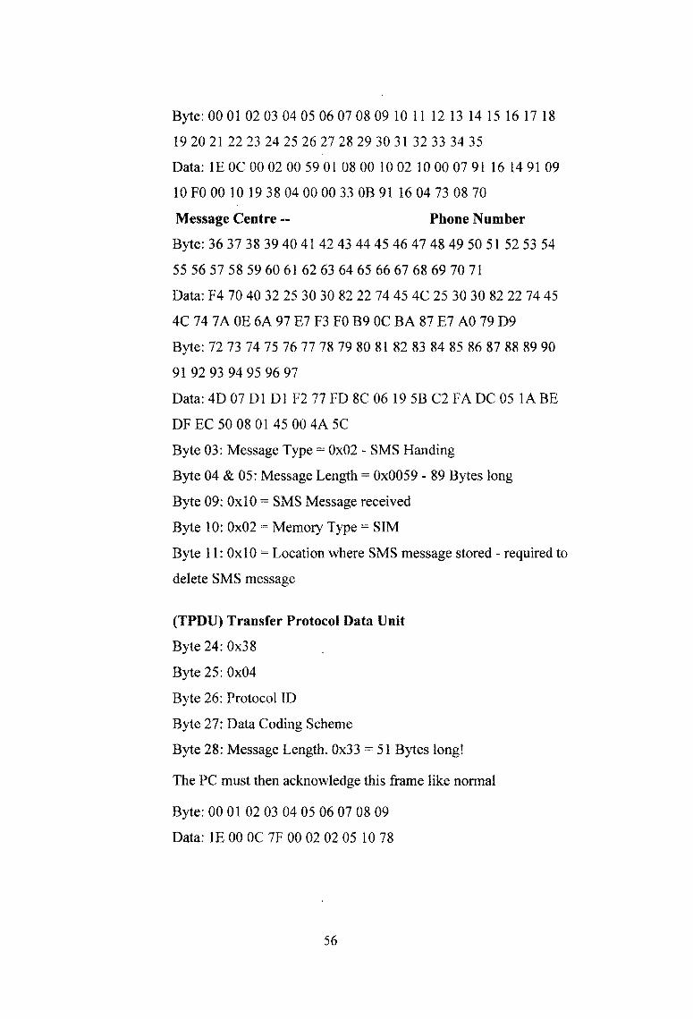
Byte: 00 01 02 03 04 05 06 07 08 09 10 11 12 13 14 15 16 17 18
19 20 21 22 23 24 25 26 27 28 29 30 31 32 33 34 35
Data: IE OC 00 02 00 59 01 08 00 10 02 10 00 07 91 16 14 91 09
10 FO 00 10 19 38 04 00 00 33 OB 91 16 04 73 08 70
Message Centre -- Phone Number
Byte: 36 37 38 39 40 41 42 43 44 45 46 47 48 49 50 51 52 53 54
55 56 57 58 59 60 61 62 63 64 65 66 67 68 69 70 71
Data: F4 70 40 32 25 30 30 82 22 74 45 4C 25 30 30 82 22 74 45
4C 74 7A OE 6A 97 E7 F3 FO B9 OC BA 87 E7 AO 79 D9
Byte: 72 73 74 75 76 77 78 79 80 81 82 83 84 85 86 87 88 89 90
91 92 93 94 95 96 97
Data: 4D 07 D1 D1 F2 77 FD 8C 06 19 5B C2 FA DC 05 1A BE
DF EC 50 08 01 45 00 4A 5C
Byte 03: Message Type = 0x02 - SMS Handing
Byte 04 & 05: Message Length = 0x0059 - 89 Bytes long
Byte 09: 0x10 = SMS Message received
Byte 10: 0x02 = Memory Type = SIM
Byte 11: 0x10 = Location where SMS message stored - required to
delete SMS message
(TPDU) Transfer Protocol Data Unit
Byte 24: 0x38
Byte 25: 0x04
Byte 26: Protocol ID
Byte 27: Data Coding Scheme
Byte 28: Message Length. 0x33 = 51 Bytes long!
The PC must then acknowledge this frame like normal
Byte: 00 01 02 03 04 05 06 07 08 09
Data: IE 00 0C 7F 00 02 02 05 10 78
56

3.6 DELETING AN SMS MESSAGE
When the phone gets sent a SMS message it sends a 'SMS Message
Received Frame' with the message attached. In this frame is the location where
the message is stored. Then next we have to do is to tell the phone to delete it!
Byte: 00 01 02 03 04 05 06 07 08 09 10 11 12 13 14 15
Data: IE 00 0C 14 00 08 00 01 00 0A 02 02 01 41 11 54
Byte 03: Message Type = 0x14 - SMS Functions
Byte 04 & 05: Message Length = 0x0008 - 08 Bytes long
Byte 6 to 8: Start of the SMS Frame Header. 0x00, 0x01, 0x00
Byte 9: OxOA Delete SMS Message
Byte 10: 0x02 = Memory Type = SIM - Make sure message is
store in this type (0x03 = phone)
Byte 11: 0x02 = Location where SMS message stored. This
location can be found in the 'receive SMS frame' (Byte 11)
Byte 12: 0x01
Byte 13: Packet Sequence Number
Byte 14 & 15: Odd & even checksum bytes.
3.7 APPLICATIONS
> Nokia F-Bus is used in ATMegal28 [19]. This will send SMS messages
from a number of alarm inputs and receive SMS messages from a number
of logic level outputs or relays.
> Nokia F-Bus is used in AVR570 processor board. It is used for JTEG
programming and debugging. It has two serial ports; one goes to the
nokia phone with the other going to the terminal for control. The two
jumpers near the F-Bus connections sets the levels for RTS and DTR.We
can receive and display hardware and software information from nokia
phone. Simple commands can be sent over the serial interface to set up
the processor and send messages etc.
57

> Nokia F-Bus is used in SMS telemetry Programmable logic Controller
(PLC). There are thousands of uses, from turning on remote pumps,
lights, monitoring cool room temperatures, open doors etc. This board
contains four relays, two optos and 8 analog to digital channels or general
logic level input/output pins. When the correct SMS message is sent to
the phone connected to this board, a relay can be turned on or off. These
relays can used to switch mains equipment of a few amps. The two opto-
isolated inputs are for alarm condition inputs. When a voltage is applied
to these inputs, a changeable alarm message is sent to the nominated
phone number. An extra 8 pin can be used as analog to digital input
sampling or just standard logic level inputs and outputs.
An optional 2x 40-character LCD panel can be added to give
instant status of the unit. The . unit runs from a 12-volt supply and is
portable so it can be used in moving equipment like portable generators
and farm equipment.
If you need to turn on a Pump connected to Relay 2 just setup the
message string for relay2 to ‘pump’ using the terminal port on the Nokia
PLC. All settings are stored in the Megal28’s internal EEPROM so none
are lossed during a period of power loss. Once this is done, just type
‘pump on’ into you phone and send a SMS to the phone connected to the
system. The relay should then turn on. To turn it off, just use the phone to
SMS ‘Pump off to the Nokia PLC. If enabled the Nokia PLC will send a
reply back to phone, to say the command was successful. If one of the
Opto-isolated inputs becomes active the Mega 128 will send a
programmed SMS message to the phone whose number is programmed
into the Nokia PLC. This message can be anything like ‘over temperature
alarm’ etc. For the more advanced projects the temperature reading could
be sent.
58

> Nokia F-Bus is used as Nokia SMS I/O controller.
> Nokia F-Bus is used in SMS car tracking system. It’s a complete GPS
based tracking system for cars, boats, containers and anything the needs
tracking. The board has GPS module, Atmel Data Flash and the SHT11
Humidity and Temperature sensor. A LCD panel can be added for a real
time status display. If any car gets stolen, just SMS this board inside the
car and it will SMS its position back. It can also SMS us, once the car
moves over a set speed.
> Nokia F-Bus is used in GPS car tracker.
59


![WiFi Command Reference - Nokia Networks · WiFi Command Reference ... — mgw-profile profile-name [create] ... — signalling-protocol protocol — no signalling-protocol](https://img.pdfslide.net/doc/110x75/5b0165527f8b9a54578e1eaa/wifi-command-reference-nokia-networks-command-reference-mgw-profile-profile-name.jpg)