Embed Size (px)
Citation preview
NON-AXISYMMETRIC CORIOLIS VIBRATORY GYROSCOPE WITH WHOLE ANGLE, FORCE REBALANCE, AND SELF-CALIBRATION A.A. Trusov1, D.M. Rozelle1, G. Atikyan1, S.A. Zotov2, B.R. Simon2, A.M. Shkel2, A.D. Meyer1
1Northrop Grumman Corporation, USA 2University of California, Irvine, USA
ABSTRACT
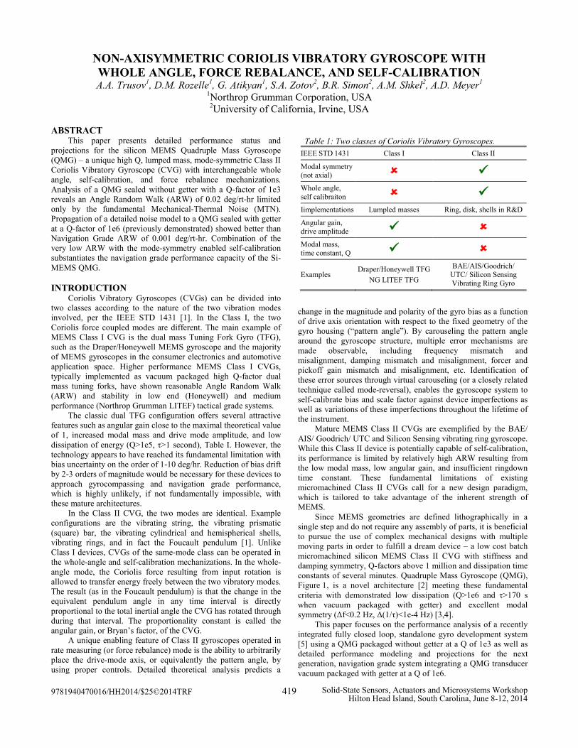
This paper presents detailed performance status and projections for the silicon MEMS Quadruple Mass Gyroscope (QMG) – a unique high Q, lumped mass, mode-symmetric Class II Coriolis Vibratory Gyroscope (CVG) with interchangeable whole angle, self-calibration, and force rebalance mechanizations. Analysis of a QMG sealed without getter with a Q-factor of 1e3 reveals an Angle Random Walk (ARW) of 0.02 deg/rt-hr limited only by the fundamental Mechanical-Thermal Noise (MTN). Propagation of a detailed noise model to a QMG sealed with getter at a Q-factor of 1e6 (previously demonstrated) showed better than Navigation Grade ARW of 0.001 deg/rt-hr. Combination of the very low ARW with the mode-symmetry enabled self-calibration substantiates the navigation grade performance capacity of the Si-MEMS QMG.
INTRODUCTION
Coriolis Vibratory Gyroscopes (CVGs) can be divided into two classes according to the nature of the two vibration modes involved, per the IEEE STD 1431 [1]. In the Class I, the two Coriolis force coupled modes are different. The main example of MEMS Class I CVG is the dual mass Tuning Fork Gyro (TFG), such as the Draper/Honeywell MEMS gyroscope and the majority of MEMS gyroscopes in the consumer electronics and automotive application space. Higher performance MEMS Class I CVGs, typically implemented as vacuum packaged high Q-factor dual mass tuning forks, have shown reasonable Angle Random Walk (ARW) and stability in low end (Honeywell) and medium performance (Northrop Grumman LITEF) tactical grade systems.
The classic dual TFG configuration offers several attractive features such as angular gain close to the maximal theoretical value of 1, increased modal mass and drive mode amplitude, and low dissipation of energy (Q>1e5, τ>1 second), Table I. However, the technology appears to have reached its fundamental limitation with bias uncertainty on the order of 1-10 deg/hr. Reduction of bias drift by 2-3 orders of magnitude would be necessary for these devices to approach gyrocompassing and navigation grade performance, which is highly unlikely, if not fundamentally impossible, with these mature architectures.
In the Class II CVG, the two modes are identical. Example configurations are the vibrating string, the vibrating prismatic (square) bar, the vibrating cylindrical and hemispherical shells, vibrating rings, and in fact the Foucault pendulum [1]. Unlike Class I devices, CVGs of the same-mode class can be operated in the whole-angle and self-calibration mechanizations. In the whole-angle mode, the Coriolis force resulting from input rotation is allowed to transfer energy freely between the two vibratory modes. The result (as in the Foucault pendulum) is that the change in the equivalent pendulum angle in any time interval is directly proportional to the total inertial angle the CVG has rotated through during that interval. The proportionality constant is called the angular gain, or Bryan’s factor, of the CVG.
A unique enabling feature of Class II gyroscopes operated in rate measuring (or force rebalance) mode is the ability to arbitrarily place the drive-mode axis, or equivalently the pattern angle, by using proper controls. Detailed theoretical analysis predicts a
change in the magnitude and polarity of the gyro bias as a function of drive axis orientation with respect to the fixed geometry of the gyro housing (“pattern angle”). By carouseling the pattern angle around the gyroscope structure, multiple error mechanisms are made observable, including frequency mismatch and misalignment, damping mismatch and misalignment, forcer and pickoff gain mismatch and misalignment, etc. Identification of these error sources through virtual carouseling (or a closely related technique called mode-reversal), enables the gyroscope system to self-calibrate bias and scale factor against device imperfections as well as variations of these imperfections throughout the lifetime of the instrument.
Mature MEMS Class II CVGs are exemplified by the BAE/ AIS/ Goodrich/ UTC and Silicon Sensing vibrating ring gyroscope. While this Class II device is potentially capable of self-calibration, its performance is limited by relatively high ARW resulting from the low modal mass, low angular gain, and insufficient ringdown time constant. These fundamental limitations of existing micromachined Class II CVGs call for a new design paradigm, which is tailored to take advantage of the inherent strength of MEMS.
Since MEMS geometries are defined lithographically in a single step and do not require any assembly of parts, it is beneficial to pursue the use of complex mechanical designs with multiple moving parts in order to fulfill a dream device – a low cost batch micromachined silicon MEMS Class II CVG with stiffness and damping symmetry, Q-factors above 1 million and dissipation time constants of several minutes. Quadruple Mass Gyroscope (QMG), Figure 1, is a novel architecture [2] meeting these fundamental criteria with demonstrated low dissipation (Q>1e6 and τ>170 s when vacuum packaged with getter) and excellent modal symmetry (Δf<0.2 Hz, Δ(1/τ)<1e-4 Hz) [3,4].
This paper focuses on the performance analysis of a recently integrated fully closed loop, standalone gyro development system [5] using a QMG packaged without getter at a Q of 1e3 as well as detailed performance modeling and projections for the next generation, navigation grade system integrating a QMG transducer vacuum packaged with getter at a Q of 1e6.
Table 1: Two classes of Coriolis Vibratory Gyroscopes. IEEE STD 1431 Class I Class II
Modal symmetry (not axial) Whole angle, self calibraiton Iimplementations Lumpled masses Ring, disk, shells in R&D
Angular gain, drive amplitude Modal mass, time constant, Q
Examples Draper/Honeywell TFG
NG LITEF TFG
BAE/AIS/Goodrich/ UTC/ Silicon Sensing Vibrating Ring Gyro
9781940470016/HH2014/$25©2014TRF 419 Solid-State Sensors, Actuators and Microsystems WorkshopHilton Head Island, South Carolina, June 8-12, 2014

QUADRUPLE MASS GYROSCOPE TRANSDUCER The optimal architecture of a high performance CVG
comprises a mode-symmetric mechanical structure with a combination of very high Q-factor and decay time constant, high Coriolis coupling (angular gain), easy frequency tuning capability [6], and low cost batch manufacturing using established silicon MEMS processes. The QMG transducer, Figure 1, comprises four symmetrically decoupled tines synchronized into balanced anti-phase motion by outer and inner lever mechanisms, providing a unique combination of ultra-low energy dissipation due to the elimination of anchor loss and isotropy of both the resonant frequency and damping [2-5]. The use of anti-phase levers instead of conventional spring flexures enables a relatively low operational frequency of several kHz, while pushing parasitic in-phase modes to higher stiffness for common mode acceleration rejection [7].
STANDALONE GYROSCOPE SYSTEM
A fully closed loop and standalone turnkey electronics suite was developed to support experimental testing and performance analysis of the QMG, Figure 2. The suite integrates a packaged MEMS transducer with an analog signal conditioning card and a digital control card in a single unit compatible with DARPA Platform for Acquisition, Logging, and Analysis of Devices for
Inertial Navigation (PALADIN). CVG control firmware running on the digital board implements the four primary servo loops: (1) drive amplitude, (2) drive frequency PLL, (3) sense Coriolis force rebalance, (4) sense quadrature. Additionally, the drive axis or the pattern angle can be (1) locked to a prescribed orientation for force rebalance operation, (2) allowed to precess in response to rotation for whole angle operation, or (3) commanded to slew at a prescribed rate for virtual carouseling or self-calibration.
WHOLE ANGLE AND SELF-CALIBRATION
A QMG with an operational frequency of 3047 Hz, as-fabricated frequency mismatch of 0.15 Hz, and a Q of 1e3 (vacuum sealed without getter) was integrated and characterized in all three mechanization modes: whole angle, self-calibration or virtual carouseling, and force rebalance rate mode. Switching between the modes is done by sending a command to the digital board through a computer GUI and does not require any hardware changes or adjustments.
To characterize operation of the whole angle mode, the gyroscope system was rotated at constant rates of ±100 deg/s for 1 hour. The data, shown in Figure 3, revealed a constant angular gain of 0.75 which agrees well with analytical modeling of the effect of the shuttle mass [3, 4]. Analysis of the linear fit to the angle data showed scale factor stability of 3 ppm, showcasing one of the inherent advantages of the whole angle mechanization of Class II
Figure 1: Quad Mass Gyroscope resonator FEM, showing the two identical mode-shapes characteristic of a Class II CVG. The QMG combines high angular gain, large drive amplitude, increased modal mass, and low dissipation advantages of MEMS tuning fork architectures with the mode-symmetry enabled stability, whole angle as well as self-calibration capabilities of Class II CVGs.
Figure 2: Photograph of the standalone CVG controls suite fully compatible with the DARPA PALADIN test platform. The bottom card is a flexible DSP/FPGA unit; the top card has analog signal conditioning. QMG in a ceramic DIP-24 with a glass lid is in the center of the top card. The system is adaptable to other CVGs through the top card interchange.
(a) Whole angle mechanization QMG output in degrees vs. time during a 100 deg/s rotation for 1 hour for a total of 0.3 million degrees, showing excellent linearity and stability.
(b) Angle data linear fit residuals, showing 3 ppm stability.
Figure 3: Whole angle demonstration using a fully closed loop QMG. The gyroscope was rotated at a 100 deg/s rate for 1 hr, showing excellent 3 ppm scale factor stability despite low Q packaging without getter
420

CVG. It should be noted that the gyroscope is successfully operated in whole angle mechanization despite the relatively low dissipation time constant of 0.1 seconds through closed loop energy control and pattern angle tracking.
Self-calibration is a closely related mechanization which uses virtual carouseling as opposed to Coriolis induced precession of the whole angle mode. Closed loop controlled slewing of the pattern angle is commanded and control signals in the gyroscope loops are observed as functions of the pattern angle, as illustrated in Figure 4. As a result virtual carouseling, mismatches and misalignments of stiffness and gains are identified in the nominally symmetric gyroscope. In addition, a ringdown measurement is automatically conducted at multiple equally spaced pattern angle orientations, making the damping mismatch and misalignment observable as well. The procedure allows self identification of these individual imperfections and enables elimination of their respective bias contributions using the math models developed by D.D. Lynch for Class II CVGs such as the HRG and the QMG.
FORCE REBALANCE RATE MODE Experiments in the force rebalance rate measuring mode
demonstrated a full scale of 1350 deg/s, a typical ARW of 0.02 to 0.05 deg/rt-hr, and a bias instability of 0.2 deg/hr or 0.05 ppm of the full scale, Figure 5. Characterization over power and temperature cycles showed excellent repeatability on the order of deg/hr, currently limited by the ARW imposed measurement accuracy. A half-month long in-run experiment was performed to assess the long term stability of the standalone gyro system, Figure 6. Self-calibration using the PLL and quadrature feedback loop command signals was employed [8,9]. The data demonstrates excellent stability of 0.2 deg/hr for integration times spanning from several minutes to several weeks (limited by the duration of the conducted experiment) with no discernible upward trend in the Allan deviation curve. This is attributed to the symmetry and mechanical stability of the QMG transducer as well as the advantages of digital closed loop gyro operation and self-calibration. PERFORMANCE ANALYSIS AND PROJECTIONS
The gyro in-run performance and the effectiveness of self-calibration against long term drifts are limited by the gyro signal-to-noise ratio or the ARW. It is thus critical to investigate the ARW governing mechanisms in the current gyro and analyze their
(a) Frequency in Hz vs. pattern angle in deg observing a 0.15 Hz native mismatch and nearly perfect alignment of axes.
(b) Time constant in sec vs. pattern angle observing a 0.001 sec variation (Δ(1/τ) of 0.1 Hz), and perfect alignment of axes.
(c) Drive amplitude command vs. pattern angle observing second and fourth harmonic variation due to the imperfections in micromachined electrostatic forcers and pickoffs.
Figure 4: Demonstration of self-calibration using virtual carouseling of the Pattern Angle (PA). Mismatches and misalignments in frequency, damping, and gains are made observable as functions of pattern angle, enabling elimination of contributions to bias using D.D. Lynch models.
Figure 5: Modified Allan deviation of force rebalance operated QMG sealed without getter at a Q of 1e3 showing 0.05 deg/rt-hr ARW and 0.2 deg/hr bias instability. The gyroscope full scale is 1350 deg/s, providing a dynamic range of 147 dB by virtue of digital force rebalance.
Figure 6: Modified Allan deviation in deg/hr vs. integration time in seconds. Half a month long in-run experiment demonstrating 0.2 deg/hr stability over several weeks using a QMG transducer packaged without getter at a Q of 1e3. Self-calibration against drifts using PLL and quadrature feedback loop command signals was employed.
421
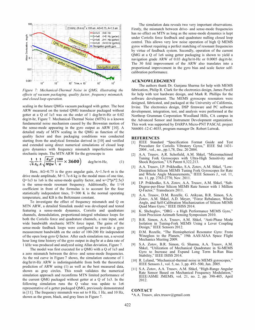
scaling in the future QMGs vacuum packaged with getter. The best ARW measured on the tested QMG transducer packaged without getter at a Q of 1e3 was on the order of 1 deg/hr/rt-Hz or 0.02 deg/rt-hr, Figure 7. Mechanical-Thermal Noise (MTN) is a known fundamental noise mechanism caused by the Brownian motion of the sense-mode appearing in the gyro output as ARW [10]. A detailed study of MTN scaling in the QMG as function of the quality factor and thus packaging conditions was conducted starting from the analytical formulas derived in [10] and verified and extended using direct numerical simulations of closed loop gyro dynamics with frequency mismatch imperfections under stochastic inputs. The MTN ARW for the gyroscope is
𝟏√𝟒
𝟏𝑨𝑮
𝟏𝑨�
𝑲𝑩𝑻𝑴𝑸𝒘
�𝟏𝟖𝟎𝝅
× 𝟑𝟔𝟎𝟎� deg/hr/rt-Hz, (1)
Here, AG=0.75 is the gyro angular gain, A=1.5e-6 m is the drive mode amplitude, M=1.7e-6 kg is the modal mass of one tine, Q=1e3 to 1e6 is the sense-mode quality factor, and w=2*pi*2.5e3 is the sense-mode resonant frequency. Additionally, the 1/√4 coefficient in front of the formulas is to account for the four statistically independent tines, T=300 K is the normal operating temperature, and KB is the Boltzmann constant.
To investigate the effect of frequency mismatch and Q on MTN ARW, a detailed Simulink model was developed and tested featuring a sense-mode dynamics, Coriolis and quadrature channels, demodulation, proportional-integral rebalance loops for both the Coriolis force and quadrature channels, a rate input, and wide bandwidth stochastic MTN force input. The gains of the sense-mode feedback loops were configured to provide a gyro measurement bandwidth on the order of 100-200 Hz independent of the open loop gyro Q factor. After each simulation run, a several hour long time history of the gyro output in deg/hr at a data rate of 1 kHz was produced and analyzed using Allan deviation, Figure 7.
The model was first executed for a QMG with a Q of 1e3 and a zero mismatch between the drive- and sense-mode frequencies. As the red curve in Figure 7 shows, the simulation outcome of 1 deg/hr/rt-Hz ARW is indistinguishable from both the theoretical prediction of ARW using (1) as well as the best measured data, shown as gray circles. This result validates the numerical simulation approach and reconfirms MTN limited performance of the current QMG packaged without getter at a Q of 1e3. In the following simulation runs the Q value was update to 1e6 representative of a getter packaged QMG, previously demonstrated in [11]. The frequency mismatch was set to 0 Hz, 1 Hz, and 10 Hz, shown as the green, black, and gray lines in Figure 7.
The simulation data reveals two very important observations. Firstly, the mismatch between drive- and sense-mode frequencies has no effect on MTN as long as the sense-mode dynamics is kept under Coriolis force feedback and quadrature nulling closed loop control. This allows very low noise operation of high Q MEMS gyros without requiring a perfect matching of resonant frequencies by virtue of feedback system. Secondly, operation of the current QMG at a Q of 1e6 using getter packaging is shown to yield a navigation grade ARW of 0.03 deg/hr/rt-Hz or 0.0005 deg/rt-hr. The 30 fold improvement of the ARW also translates into a proportional improvement in the gyro bias and scale factor self-calibration performance. ACKNOWLEDGMENT
The authors thank Dr. Gunjana Sharma for help with MEMS fabrication, Philip R. Clark for the electronics design, James Pavell for help with test hardware design, and Mark R. Phillips for the software development. The MEMS gyroscope resonators were designed, fabricated, and packaged at the University of California, Irvine. The electronics design, DSP firmware and PC software development, integration, test, and analysis were performed at the Northrop Grumman Corporation Woodland Hills, CA campus in the Advanced Sensor and Instrument Development organization. This work was supported by DARPA Micro-PNT PASCAL project N66001-12-C-4035, program manager Dr. Robert Lutwak. REFERENCES [1] IEEE Standard “Specification Format Guide and Test
Procedure for Coriolis Vibratory Gyros,” IEEE Std 1431-2004 , vol., no., pp.1,78, Dec. 20 2004.
[2] A.A. Trusov, A.R. Schofield, A.M. Shkel, “Micromachined Tuning Fork Gyroscopes with Ultra-High Sensitivity and Shock Rejection,” US Patent 8,322,213.
[3] A.A. Trusov, I.P. Prikhodko, S.A. Zotov, A.M. Shkel, “Low-Dissipation Silicon MEMS Tuning Fork Gyroscopes for Rate and Whole Angle Measurements,” IEEE Sensors J., vol. 11, no. 11, pp. 2763-2770, Nov. 2011.
[4] I.P. Prikhodko, S.A. Zotov, A.A. Trusov, A.M. Shkel, “Sub-Degree-per-Hour Silicon MEMS Rate Sensor with 1 Million Q-Factor,” Transducers 2011.
[5] A.A. Trusov, D.M. Rozelle, G. Atikyan, B.R. Simon, S.A. Zotov, A.M. Shkel, A.D. Meyer, “Force Rebalance, Whole Angle, and Self-Calibration Mechanization of Silicon MEMS Quad Mass Gyro,” IEEE ISISS 2014.
[6] K. Shcheglov, “DRG - a High Performance MEMS Gyro,” Joint Precision Azimuth Sensing Symposium 2010.
[7] B.R. Simon, A.A. Trusov, A.M. Shkel, “Anti-Phase Mode Isolation in Tuning-Fork MEMS Using a Lever Coupling Design,” IEEE Sensors 2012.
[8] D.M. Rozelle, “The Hemispherical Resonator Gyro: From Wineglass to the Planets,” 19th AAS/AIAA Space Flight Mechanics Meeting 2009.
[9] S.A. Zotov, B.R. Simon, G. Sharma, A.A. Trusov, A.M. Shkel, “Utilization of Mechanical Quadrature in Si-MEMS Gyro to Increase and Expand Long Term In-Run Bias Stability,” IEEE ISISS 2014.
[10] R. Leland, “Mechanical-thermal noise in MEMS gyroscopes,” IEEE Sensors J., vol. 5, no. 3, pp. 493–500, Jun. 2005.
[11] S.A. Zotov, A.A. Trusov, A.M. Shkel, “High-Range Angular Rate Sensor Based on Mechanical Frequency Modulation,” IEEE/ASME JMEMS, vol. 21, no. 2, pp. 398-405, April 2012.
CONTACT *A.A. Trusov, [email protected]
Figure 7: Mechanical-Thermal Noise in QMG, illustrating the effects of vacuum packaging, quality factor, frequency mismatch, and closed loop operation.
422


![NON-AXISYMMETRIC CORIOLIS VIBRATORY ......Coriolis coupling (angular gain), easy frequency tuning capability [6], and low cost batch manufacturing using established silicon MEMS processes](https://img.pdfslide.net/doc/110x75/6114d42923fafc1dc73bc5ac/non-axisymmetric-coriolis-vibratory-coriolis-coupling-angular-gain-easy.jpg)