Embed Size (px)
Citation preview

Non-linear 3D FEM Pounding Analysis of a Bridge
Structure to Multi-Component Spatially Varying Ground Motions K. Bi & H. Hao University of Western Australia, Australia W. Ren Hefei University of Technology, China
SUMMARY: Earthquake-induced poundings between different components of multi-span simply-supported bridges may lead to substantial damage or even collapse of structures. Previous studies of pounding between adjacent bridge structures during earthquakes were usually based on the simplified lumped mass model or beam-column element model. It has been proved that these 1D or 2D models can be used to calculate the pounding responses if only the longitudinal ground excitation is considered. The detailed 3D finite element model is necessary to model the torsional response induced by spatially varying transverse ground motions and the corresponding eccentric poundings due to torsional responses of adjacent bridge structures. Pounding usually causes local damage near the impacting area, however, the nonlinearities of the materials and damage were usually not considered in the previous studies. In the present paper, the detailed three-dimensional pounding response analysis of a two-span simply-supported bridge structure to multi-component spatially varying ground motions are conducted using the explicit finite element code LS-DYNA. The nonlinearities of the material behavior and damage are considered. The pounding induced local damage is examined. The results clearly demonstrate the necessity of using non-linear 3D FEM analysis to realistically model the pounding damages of bridge structures during earthquakes. Keywords: Pounding, 3D model, damage mechanism, non-linear material 1. INTRODUCTION Various types of damage were observed in bridge structures during previous major earthquakes. In terms of the damage locations, they can be classified as damage to superstructures, bearings and substructures. This paper mainly focuses on the damage to superstructures. The most common form of damage to superstructures is due to pounding of adjacent segments at the expansion joints as shown in Figs. 1.1(a) and 1.1(b). Unseating damage can occur when the opening relative displacement exceeds the seating length as shown in Fig. 1.1(c). Large relative displacement in the transverse direction can result in the dislocation of adjacent bridge segments. Figs. 1.1(d) and 1.1(e) show the typical dislocation damages at the expansion joints. All these damage can attribute to the large out-of-phase movements between adjacent bridge segments (either in the longitudinal direction or lateral direction of the bridge). There are many reasons that may result in the out-of-phase movements, such as the different characteristics of adjacent bridge structures, the spatially varying ground motions and the interaction between the foundation and the surrounding soil (soil-structure interaction). This paper concentrates on the pounding damage of bridge structures to spatially varying ground motions. The unseating and dislocation potentials, as will be demonstrated in Section 4, are also examined. Pounding is an extremely complex phenomenon involving damage due to plastic deformation, local cracking or crushing, fracturing due to impact, and friction when the adjacent components are in contact with each other. To simplify the analysis, most previous studies of pounding responses of adjacent bridge structures were usually based on the lumped mass model (Malhotra 1998; Jankowski et al. 1998; Ruangrassamee and Kawashima 2001; DesRoches and Muthukumar 2002; Chouw and Hao 2005, 2008) or beam column element model (Jankowski et al. 2000; Chouw et al. 2006). It has been proved that these simplified models can only be used to calculate the point-to-point pounding

responses under the longitudinal seismic excitation (Bi and Hao 2010). In real bridge structure under seismic loading, pounding could take place along the entire surfaces of the adjacent structures. Moreover, it was observed from previous earthquakes that most poundings actually occurred at the corners of adjacent bridge decks. This is because torsional response of the adjacent decks induced by spatially varying ground motions at multiple bridge supports resulted in eccentric poundings. To more realistically model the surface-to-surface and torsional response induced eccentric poundings, the detailed 3D finite element model is necessary (Bi and Hao 2010). Zanardo et al. (2002) modeled the box-section bridge girders with shell elements and piers with beam-column elements, and carried out a parametrical study of pounding phenomenon of a multi-span simply-supported bridge with base isolation devices. Julian et al. (2006) evaluated the effectiveness of cable restrainers to mitigate earthquake damage through connection between isolated and non-isolated sections of curved steel viaducts using 3D non-linear finite element response analysis. Although 3D FE model of bridge structures were developed in those two studies, the surface-to-surface pounding were not considered. The pounding phenomenon in these studies was simulated by the contact elements which linked the external nodes of adjacent segments together. In other words, the pounding locations are predefined, whereas in reality the pounding locations constantly change during the earthquake excitations owing to the complex 3D responses of the bridge structures. Zhu et al. (2002) proposed a 3D contact-friction model to analyze pounding between bridge girders. This method conducts searches of pounding locations at every time step, therefore, overcomes the shortcomings of predefining the pounding locations. It, however, could not model material non-linearities during contacts, and the task to search contact pairs is very time consuming and the searching algorithm is relatively complicated. More recently, Bi and Hao (2010) studied the pounding responses between the abutment and adjacent bridge deck and between two adjacent bridge decks of a two-span simply-supported bridge located on a canyon site by using the explicit finite element code LS-DYNA (2007). The surface-to-surface and torsional response induced eccentric poundings were considered in the study, however, the material non-linearities and pounding induced local damages were not modeled.
Figure 1.1. Typical seismic induced damage after previous earthquakes (a), (b) pounding damage, (c) unseating damage and (d), (e) dislocation damage
In this study, pounding responses between the abutment and the adjacent bridge girder and between two adjacent bridge girders of a two-span simply-supported bridge crossing a canyon site are investigated. A detailed 3D FE model is developed. The bridge components including the bridge girders, abutments, pier, bearings, longitudinal reinforcement bars and stirrups are considered in the model. The non-linear material behaviors of the concrete and the steel rebar are considered. The spatially varying ground motions are stochastically simulated. The damage mechanism of the bridge under multi-component spatially varying seismic loadings is examined. 2. BRIDGE MODEL Fig. 2.1(a) shows the elevation view of a two-span simply-supported bridge crossing a canyon site. The cross sections of the bridge girder, abutment, central pier and the bearings are shown in Figs.
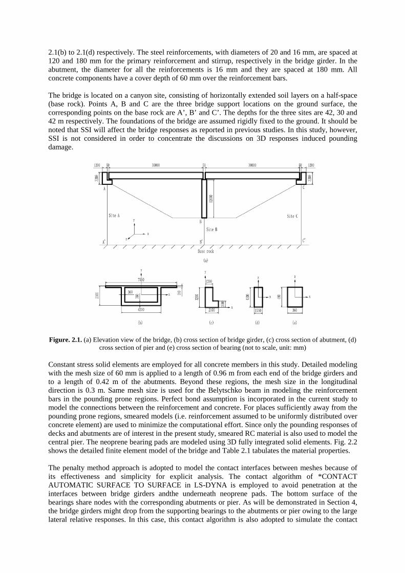
2.1(b) to 2.1(d) respectively. The steel reinforcements, with diameters of 20 and 16 mm, are spaced at 120 and 180 mm for the primary reinforcement and stirrup, respectively in the bridge girder. In the abutment, the diameter for all the reinforcements is 16 mm and they are spaced at 180 mm. All concrete components have a cover depth of 60 mm over the reinforcement bars. The bridge is located on a canyon site, consisting of horizontally extended soil layers on a half-space (base rock). Points A, B and C are the three bridge support locations on the ground surface, the corresponding points on the base rock are A’, B’ and C’. The depths for the three sites are 42, 30 and 42 m respectively. The foundations of the bridge are assumed rigidly fixed to the ground. It should be noted that SSI will affect the bridge responses as reported in previous studies. In this study, however, SSI is not considered in order to concentrate the discussions on 3D responses induced pounding damage.
Figure. 2.1. (a) Elevation view of the bridge, (b) cross section of bridge girder, (c) cross section of abutment, (d) cross section of pier and (e) cross section of bearing (not to scale, unit: mm)
Constant stress solid elements are employed for all concrete members in this study. Detailed modeling with the mesh size of 60 mm is applied to a length of 0.96 m from each end of the bridge girders and to a length of 0.42 m of the abutments. Beyond these regions, the mesh size in the longitudinal direction is 0.3 m. Same mesh size is used for the Belytschko beam in modeling the reinforcement bars in the pounding prone regions. Perfect bond assumption is incorporated in the current study to model the connections between the reinforcement and concrete. For places sufficiently away from the pounding prone regions, smeared models (i.e. reinforcement assumed to be uniformly distributed over concrete element) are used to minimize the computational effort. Since only the pounding responses of decks and abutments are of interest in the present study, smeared RC material is also used to model the central pier. The neoprene bearing pads are modeled using 3D fully integrated solid elements. Fig. 2.2 shows the detailed finite element model of the bridge and Table 2.1 tabulates the material properties. The penalty method approach is adopted to model the contact interfaces between meshes because of its effectiveness and simplicity for explicit analysis. The contact algorithm of *CONTACT AUTOMATIC SURFACE TO SURFACE in LS-DYNA is employed to avoid penetration at the interfaces between bridge girders andthe underneath neoprene pads. The bottom surface of the bearings share nodes with the corresponding abutments or pier. As will be demonstrated in Section 4, the bridge girders might drop from the supporting bearings to the abutments or pier owing to the large lateral relative responses. In this case, this contact algorithm is also adopted to simulate the contact
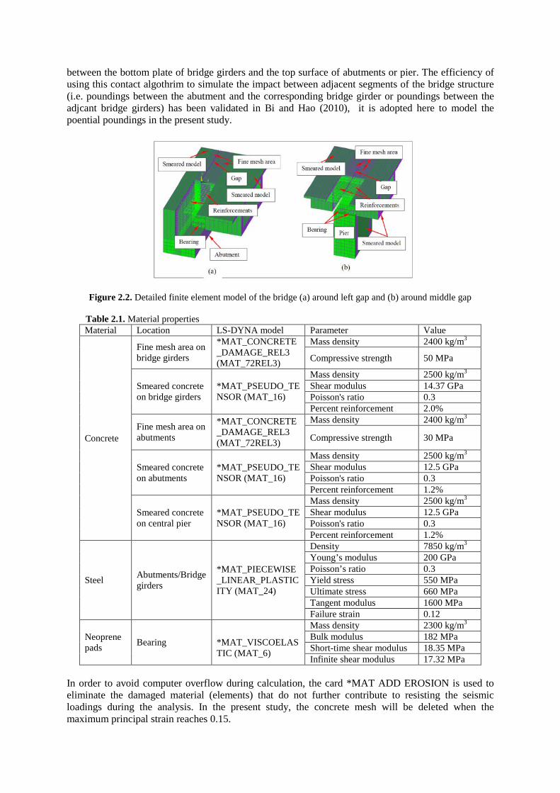
between the bottom plate of bridge girders and the top surface of abutments or pier. The efficiency of using this contact algothrim to simulate the impact between adjacent segments of the bridge structure (i.e. poundings between the abutment and the corresponding bridge girder or poundings between the adjcant bridge girders) has been validated in Bi and Hao (2010), it is adopted here to model the poential poundings in the present study.
Figure 2.2. Detailed finite element model of the bridge (a) around left gap and (b) around middle gap
Table 2.1. Material properties Material Location LS-DYNA model Parameter Value
Concrete
Fine mesh area on bridge girders
*MAT_CONCRETE_DAMAGE_REL3 (MAT_72REL3)
Mass density 2400 kg/m3
Compressive strength 50 MPa
Smeared concrete on bridge girders
*MAT_PSEUDO_TENSOR (MAT_16)
Mass density 2500 kg/m3 Shear modulus 14.37 GPa Poisson's ratio 0.3 Percent reinforcement 2.0%
Fine mesh area on abutments
*MAT_CONCRETE_DAMAGE_REL3 (MAT_72REL3)
Mass density 2400 kg/m3
Compressive strength 30 MPa
Smeared concrete on abutments
*MAT_PSEUDO_TENSOR (MAT_16)
Mass density 2500 kg/m3 Shear modulus 12.5 GPa Poisson's ratio 0.3 Percent reinforcement 1.2%
Smeared concrete on central pier
*MAT_PSEUDO_TENSOR (MAT_16)
Mass density 2500 kg/m3 Shear modulus 12.5 GPa Poisson's ratio 0.3 Percent reinforcement 1.2%
Steel Abutments/Bridge girders
*MAT_PIECEWISE_LINEAR_PLASTICITY (MAT_24)
Density 7850 kg/m3 Young’s modulus 200 GPa Poisson’s ratio 0.3 Yield stress 550 MPa Ultimate stress 660 MPa Tangent modulus 1600 MPa Failure strain 0.12
Neoprene pads Bearing
*MAT_VISCOELASTIC (MAT_6)
Mass density 2300 kg/m3 Bulk modulus 182 MPa Short-time shear modulus 18.35 MPa Infinite shear modulus 17.32 MPa
In order to avoid computer overflow during calculation, the card *MAT ADD EROSION is used to eliminate the damaged material (elements) that do not further contribute to resisting the seismic loadings during the analysis. In the present study, the concrete mesh will be deleted when the maximum principal strain reaches 0.15.
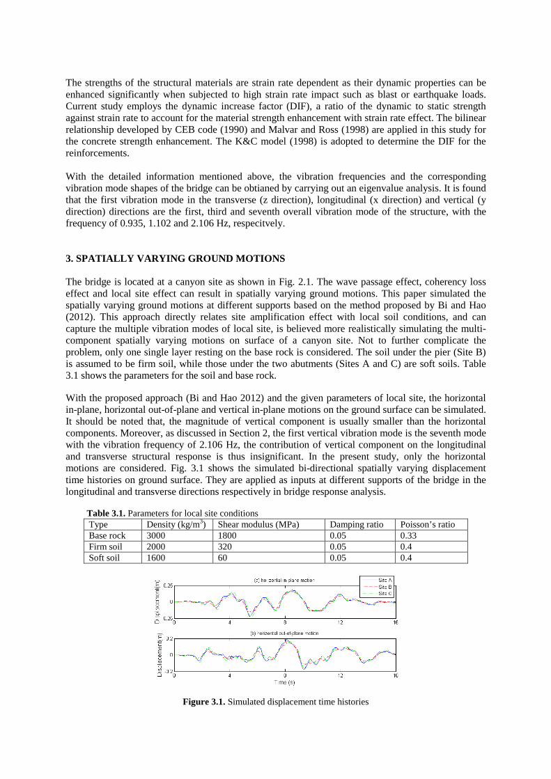
The strengths of the structural materials are strain rate dependent as their dynamic properties can be enhanced significantly when subjected to high strain rate impact such as blast or earthquake loads. Current study employs the dynamic increase factor (DIF), a ratio of the dynamic to static strength against strain rate to account for the material strength enhancement with strain rate effect. The bilinear relationship developed by CEB code (1990) and Malvar and Ross (1998) are applied in this study for the concrete strength enhancement. The K&C model (1998) is adopted to determine the DIF for the reinforcements. With the detailed information mentioned above, the vibration frequencies and the corresponding vibration mode shapes of the bridge can be obtianed by carrying out an eigenvalue analysis. It is found that the first vibration mode in the transverse (z direction), longitudinal (x direction) and vertical (y direction) directions are the first, third and seventh overall vibration mode of the structure, with the frequency of 0.935, 1.102 and 2.106 Hz, respecitvely. 3. SPATIALLY VARYING GROUND MOTIONS The bridge is located at a canyon site as shown in Fig. 2.1. The wave passage effect, coherency loss effect and local site effect can result in spatially varying ground motions. This paper simulated the spatially varying ground motions at different supports based on the method proposed by Bi and Hao (2012). This approach directly relates site amplification effect with local soil conditions, and can capture the multiple vibration modes of local site, is believed more realistically simulating the multi-component spatially varying motions on surface of a canyon site. Not to further complicate the problem, only one single layer resting on the base rock is considered. The soil under the pier (Site B) is assumed to be firm soil, while those under the two abutments (Sites A and C) are soft soils. Table 3.1 shows the parameters for the soil and base rock. With the proposed approach (Bi and Hao 2012) and the given parameters of local site, the horizontal in-plane, horizontal out-of-plane and vertical in-plane motions on the ground surface can be simulated. It should be noted that, the magnitude of vertical component is usually smaller than the horizontal components. Moreover, as discussed in Section 2, the first vertical vibration mode is the seventh mode with the vibration frequency of 2.106 Hz, the contribution of vertical component on the longitudinal and transverse structural response is thus insignificant. In the present study, only the horizontal motions are considered. Fig. 3.1 shows the simulated bi-directional spatially varying displacement time histories on ground surface. They are applied as inputs at different supports of the bridge in the longitudinal and transverse directions respectively in bridge response analysis. Table 3.1. Parameters for local site conditions
Type Density (kg/m3) Shear modulus (MPa) Damping ratio Poisson’s ratio Base rock 3000 1800 0.05 0.33 Firm soil 2000 320 0.05 0.4 Soft soil 1600 60 0.05 0.4
Figure 3.1. Simulated displacement time histories
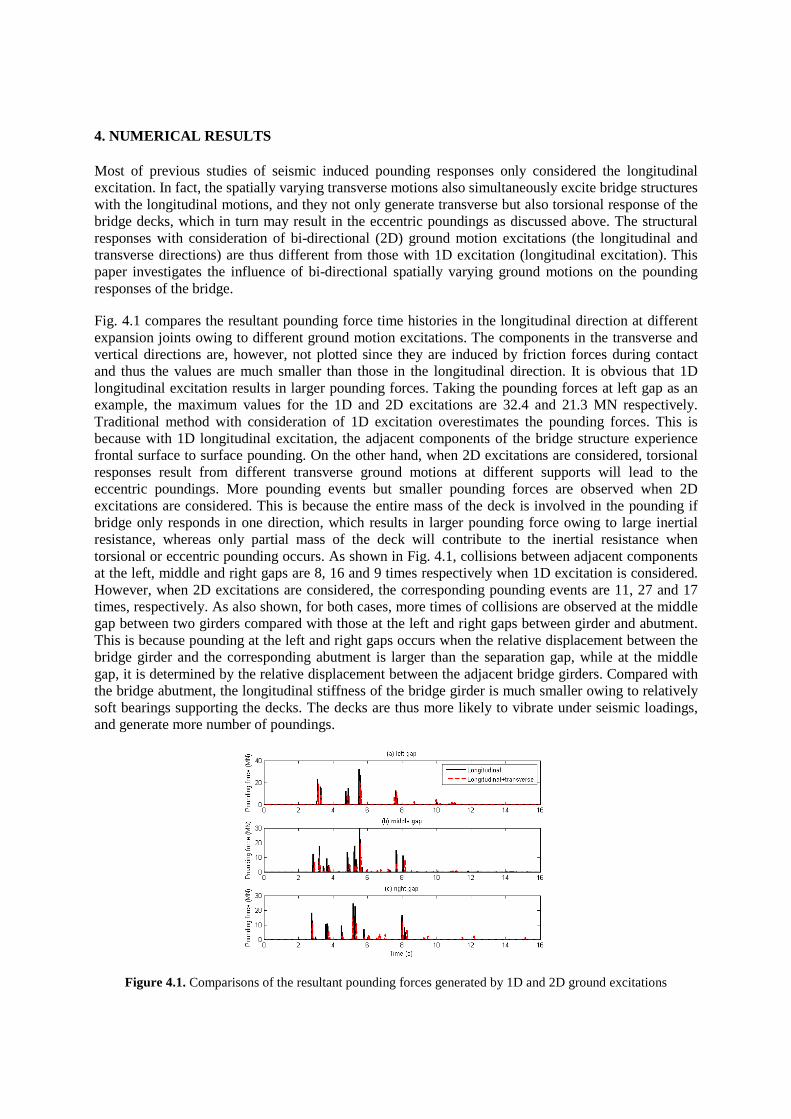
4. NUMERICAL RESULTS Most of previous studies of seismic induced pounding responses only considered the longitudinal excitation. In fact, the spatially varying transverse motions also simultaneously excite bridge structures with the longitudinal motions, and they not only generate transverse but also torsional response of the bridge decks, which in turn may result in the eccentric poundings as discussed above. The structural responses with consideration of bi-directional (2D) ground motion excitations (the longitudinal and transverse directions) are thus different from those with 1D excitation (longitudinal excitation). This paper investigates the influence of bi-directional spatially varying ground motions on the pounding responses of the bridge. Fig. 4.1 compares the resultant pounding force time histories in the longitudinal direction at different expansion joints owing to different ground motion excitations. The components in the transverse and vertical directions are, however, not plotted since they are induced by friction forces during contact and thus the values are much smaller than those in the longitudinal direction. It is obvious that 1D longitudinal excitation results in larger pounding forces. Taking the pounding forces at left gap as an example, the maximum values for the 1D and 2D excitations are 32.4 and 21.3 MN respectively. Traditional method with consideration of 1D excitation overestimates the pounding forces. This is because with 1D longitudinal excitation, the adjacent components of the bridge structure experience frontal surface to surface pounding. On the other hand, when 2D excitations are considered, torsional responses result from different transverse ground motions at different supports will lead to the eccentric poundings. More pounding events but smaller pounding forces are observed when 2D excitations are considered. This is because the entire mass of the deck is involved in the pounding if bridge only responds in one direction, which results in larger pounding force owing to large inertial resistance, whereas only partial mass of the deck will contribute to the inertial resistance when torsional or eccentric pounding occurs. As shown in Fig. 4.1, collisions between adjacent components at the left, middle and right gaps are 8, 16 and 9 times respectively when 1D excitation is considered. However, when 2D excitations are considered, the corresponding pounding events are 11, 27 and 17 times, respectively. As also shown, for both cases, more times of collisions are observed at the middle gap between two girders compared with those at the left and right gaps between girder and abutment. This is because pounding at the left and right gaps occurs when the relative displacement between the bridge girder and the corresponding abutment is larger than the separation gap, while at the middle gap, it is determined by the relative displacement between the adjacent bridge girders. Compared with the bridge abutment, the longitudinal stiffness of the bridge girder is much smaller owing to relatively soft bearings supporting the decks. The decks are thus more likely to vibrate under seismic loadings, and generate more number of poundings.
Figure 4.1. Comparisons of the resultant pounding forces generated by 1D and 2D ground excitations
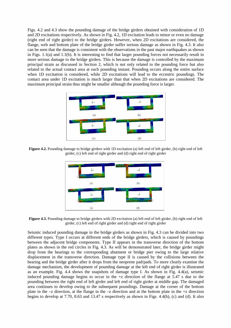
Figs. 4.2 and 4.3 show the pounding damage of the bridge girders obtained with consideration of 1D and 2D excitations respectively. As shown in Fig. 4.2, 1D excitation leads to minor or even no damage (right end of right girder) to the bridge girders. However, when 2D excitations are considered, the flange, web and bottom plate of the bridge girder suffer serious damage as shown in Fig. 4.3. It also can be seen that the damage is consistent with the observations in the past major earthquakes as shown in Figs. 1.1(a) and 1.1(b). It is interesting to find that larger pounding forces not necessarily result in more serious damage to the bridge girders. This is because the damage is controlled by the maximum principal strain as discussed in Section 2, which is not only related to the pounding force but also related to the actual contact area at each pounding instant. Pounding occurs along the entire surface when 1D excitation is considered, while 2D excitations will lead to the eccentric poundings. The contact area under 1D excitation is much larger than that when 2D excitations are considered. The maximum principal strain thus might be smaller although the pounding force is larger.
Figure 4.2. Pounding damage to bridge girders with 1D excitation (a) left end of left girder, (b) right end of left girder, (c) left end of right girder and (d) right end of right girder
Figure 4.3. Pounding damage to bridge girders with 2D excitation (a) left end of left girder, (b) right end of left girder, (c) left end of right girder and (d) right end of right girder
Seismic induced pounding damage in the bridge girders as shown in Fig. 4.3 can be divided into two different types. Type I occurs at different ends of the bridge girders, which is caused by poundings between the adjacent bridge components. Type II appears in the transverse direction of the bottom plates as shown in the red circles in Fig. 4.3. As will be demonstrated later, the bridge girder might drop from the bearings to the corresponding abutment or bridge pier owing to the large relative displacement in the transverse direction. Damage type II is caused by the collisions between the bearing and the bridge girder after it drops from the neoprene pad/pads. To more clearly examine the damage mechanism, the development of pounding damage at the left end of right girder is illustrated as an example. Fig. 4.4 shows the snapshots of damage type I. As shown in Fig. 4.4(a), seismic induced pounding damage begins to occur in the +z direction of the flange at 5.47 s due to the pounding between the right end of left girder and left end of right girder at middle gap. The damaged area continues to develop owing to the subsequent poundings. Damage at the corner of the bottom plate in the –z direction, at the flange in the –z direction and at the bottom plate in the +z direction begins to develop at 7.70, 8.63 and 13.47 s respectively as shown in Figs. 4.4(b), (c) and (d). It also
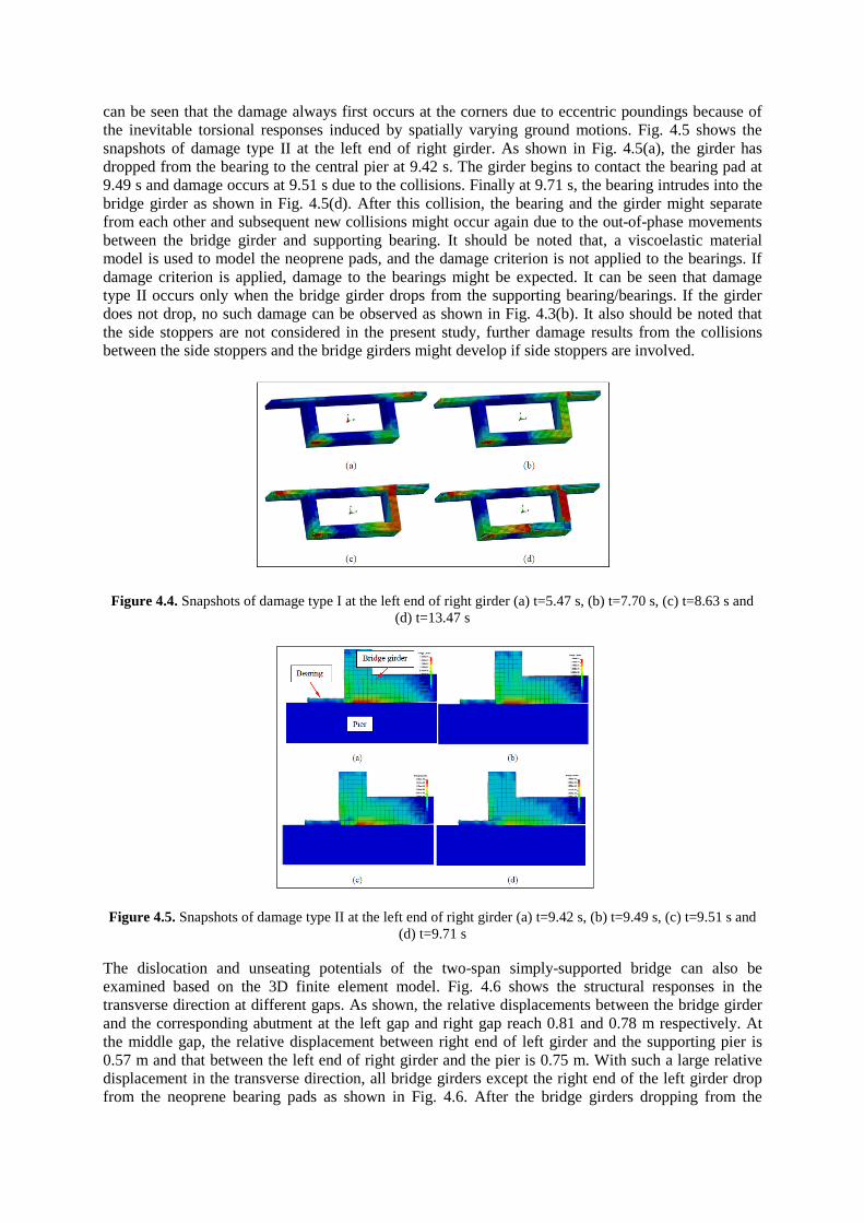
can be seen that the damage always first occurs at the corners due to eccentric poundings because of the inevitable torsional responses induced by spatially varying ground motions. Fig. 4.5 shows the snapshots of damage type II at the left end of right girder. As shown in Fig. 4.5(a), the girder has dropped from the bearing to the central pier at 9.42 s. The girder begins to contact the bearing pad at 9.49 s and damage occurs at 9.51 s due to the collisions. Finally at 9.71 s, the bearing intrudes into the bridge girder as shown in Fig. 4.5(d). After this collision, the bearing and the girder might separate from each other and subsequent new collisions might occur again due to the out-of-phase movements between the bridge girder and supporting bearing. It should be noted that, a viscoelastic material model is used to model the neoprene pads, and the damage criterion is not applied to the bearings. If damage criterion is applied, damage to the bearings might be expected. It can be seen that damage type II occurs only when the bridge girder drops from the supporting bearing/bearings. If the girder does not drop, no such damage can be observed as shown in Fig. 4.3(b). It also should be noted that the side stoppers are not considered in the present study, further damage results from the collisions between the side stoppers and the bridge girders might develop if side stoppers are involved.
Figure 4.4. Snapshots of damage type I at the left end of right girder (a) t=5.47 s, (b) t=7.70 s, (c) t=8.63 s and (d) t=13.47 s
Figure 4.5. Snapshots of damage type II at the left end of right girder (a) t=9.42 s, (b) t=9.49 s, (c) t=9.51 s and (d) t=9.71 s
The dislocation and unseating potentials of the two-span simply-supported bridge can also be examined based on the 3D finite element model. Fig. 4.6 shows the structural responses in the transverse direction at different gaps. As shown, the relative displacements between the bridge girder and the corresponding abutment at the left gap and right gap reach 0.81 and 0.78 m respectively. At the middle gap, the relative displacement between right end of left girder and the supporting pier is 0.57 m and that between the left end of right girder and the pier is 0.75 m. With such a large relative displacement in the transverse direction, all bridge girders except the right end of the left girder drop from the neoprene bearing pads as shown in Fig. 4.6. After the bridge girders dropping from the
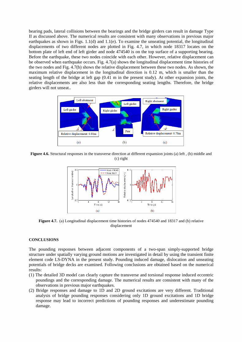
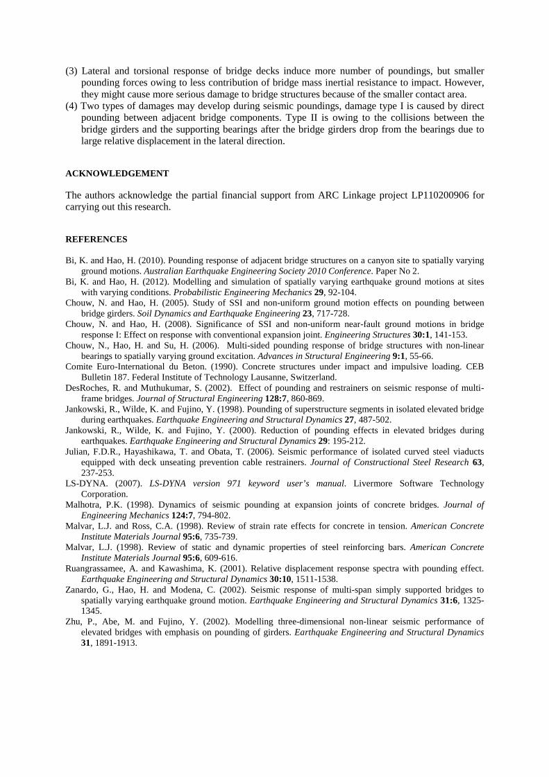
bearing pads, lateral collisions between the bearings and the bridge girders can result in damage Type II as discussed above. The numerical results are consistent with many observations in previous major earthquakes as shown in Figs. 1.1(d) and 1.1(e). To examine the unseating potential, the longitudinal displacements of two different nodes are plotted in Fig. 4.7, in which node 18317 locates on the bottom plate of left end of left girder and node 474540 is on the top surface of a supporting bearing. Before the earthquake, these two nodes coincide with each other. However, relative displacement can be observed when earthquake occurs. Fig. 4.7(a) shows the longitudinal displacement time histories of the two nodes and Fig. 4.7(b) shows the relative displacement between these two nodes. As shown, the maximum relative displacement in the longitudinal direction is 0.12 m, which is smaller than the seating length of the bridge at left gap (0.41 m in the present study). At other expansion joints, the relative displacements are also less than the corresponding seating lengths. Therefore, the bridge girders will not unseat..
Figure 4.6. Structural responses in the transverse direction at different expansion joints (a) left , (b) middle and (c) right
Figure 4.7. (a) Longitudinal displacement time histories of nodes 474540 and 18317 and (b) relative displacement
CONCLUSIONS The pounding responses between adjacent components of a two-span simply-supported bridge structure under spatially varying ground motions are investigated in detail by using the transient finite element code LS-DYNA in the present study. Pounding induced damage, dislocation and unseating potentials of bridge decks are examined. Following conclusions are obtained based on the numerical results: (1) The detailed 3D model can clearly capture the transverse and torsional response induced eccentric
poundings and the corresponding damage. The numerical results are consistent with many of the observations in previous major earthquakes.
(2) Bridge responses and damage to 1D and 2D ground excitations are very different. Traditional analysis of bridge pounding responses considering only 1D ground excitations and 1D bridge response may lead to incorrect predictions of pounding responses and underestimate pounding damage.
(3) Lateral and torsional response of bridge decks induce more number of poundings, but smaller pounding forces owing to less contribution of bridge mass inertial resistance to impact. However, they might cause more serious damage to bridge structures because of the smaller contact area.
(4) Two types of damages may develop during seismic poundings, damage type I is caused by direct pounding between adjacent bridge components. Type II is owing to the collisions between the bridge girders and the supporting bearings after the bridge girders drop from the bearings due to large relative displacement in the lateral direction.
ACKNOWLEDGEMENT The authors acknowledge the partial financial support from ARC Linkage project LP110200906 for carrying out this research.
REFERENCES Bi, K. and Hao, H. (2010). Pounding response of adjacent bridge structures on a canyon site to spatially varying
ground motions. Australian Earthquake Engineering Society 2010 Conference. Paper No 2. Bi, K. and Hao, H. (2012). Modelling and simulation of spatially varying earthquake ground motions at sites
with varying conditions. Probabilistic Engineering Mechanics 29, 92-104. Chouw, N. and Hao, H. (2005). Study of SSI and non-uniform ground motion effects on pounding between
bridge girders. Soil Dynamics and Earthquake Engineering 23, 717-728. Chouw, N. and Hao, H. (2008). Significance of SSI and non-uniform near-fault ground motions in bridge
response I: Effect on response with conventional expansion joint. Engineering Structures 30:1, 141-153. Chouw, N., Hao, H. and Su, H. (2006). Multi-sided pounding response of bridge structures with non-linear
bearings to spatially varying ground excitation. Advances in Structural Engineering 9:1, 55-66. Comite Euro-International du Beton. (1990). Concrete structures under impact and impulsive loading. CEB
Bulletin 187. Federal Institute of Technology Lausanne, Switzerland. DesRoches, R. and Muthukumar, S. (2002). Effect of pounding and restrainers on seismic response of multi-
frame bridges. Journal of Structural Engineering 128:7, 860-869. Jankowski, R., Wilde, K. and Fujino, Y. (1998). Pounding of superstructure segments in isolated elevated bridge
during earthquakes. Earthquake Engineering and Structural Dynamics 27, 487-502. Jankowski, R., Wilde, K. and Fujino, Y. (2000). Reduction of pounding effects in elevated bridges during
earthquakes. Earthquake Engineering and Structural Dynamics 29: 195-212. Julian, F.D.R., Hayashikawa, T. and Obata, T. (2006). Seismic performance of isolated curved steel viaducts
equipped with deck unseating prevention cable restrainers. Journal of Constructional Steel Research 63, 237-253.
LS-DYNA. (2007). LS-DYNA version 971 keyword user’s manual. Livermore Software Technology Corporation.
Malhotra, P.K. (1998). Dynamics of seismic pounding at expansion joints of concrete bridges. Journal of Engineering Mechanics 124:7, 794-802.
Malvar, L.J. and Ross, C.A. (1998). Review of strain rate effects for concrete in tension. American Concrete Institute Materials Journal 95:6, 735-739.
Malvar, L.J. (1998). Review of static and dynamic properties of steel reinforcing bars. American Concrete Institute Materials Journal 95:6, 609-616.
Ruangrassamee, A. and Kawashima, K. (2001). Relative displacement response spectra with pounding effect. Earthquake Engineering and Structural Dynamics 30:10, 1511-1538.
Zanardo, G., Hao, H. and Modena, C. (2002). Seismic response of multi-span simply supported bridges to spatially varying earthquake ground motion. Earthquake Engineering and Structural Dynamics 31:6, 1325-1345.
Zhu, P., Abe, M. and Fujino, Y. (2002). Modelling three-dimensional non-linear seismic performance of elevated bridges with emphasis on pounding of girders. Earthquake Engineering and Structural Dynamics 31, 1891-1913.