Embed Size (px)
Citation preview
Non-Separable Extensions of Quadrature Mirror Filters to Multiple Dimensions
Quadrature Mirror Filter (QMF) banks have been used in a variety of one-dimensional signal processing applications, and have been applied separably in two dimensions. As with most one-dimen- sional filters, separable extension to multiple dimensions pro- duces a transform in which the orientation selectivity of some of the high-pass filters is poor. We describe generalized non-separa- ble extensions of QMF banks to two and three dimensions, in which the orientation specificity of the high-pass filters is greatly improved. In particular, we discuss extensions to two dimensions with hexagonal symmetry, and three dimensional spatio-temporal extensions with rhombic-dodecahedral symmetry. Although these filters are conceived and designed on non-standard sampling lat- tices, they may be applied to rectangularly sampled images. As in one dimension, these transformations may be hierarchically cas- caded to form a multi-scale “pyramid” representation. We design a set of example filters and apply them to the problems of image compression, progressive transmission, orientation analysis, and motion analysis.
INTRODUCTION
Sub-band transforms have been successfully employed in many areas of signal processing. For many applications, especially in image processing, researchers have advocated the use of sub-band transforms that divide the frequency spectrum into octave bandwidth pieces [I]-[4]. In such a transform the basis functions represent information at spa- tial scales which are related by powers of two.
A particularly useful one-dimensional orthogonal sub- band transform i s the Quadrature Mirror Filter (QMF) bank, which was introduced by Croisier et al. [SI, [6]. These filters are used in an analysis/synthesis system which decomposes a signal into high-pass and low-pass frequency sub-bands. They are also well-suited for octave band splitting, since they can be applied recursively to split the low-pass sub- band. Vaidyanathan developed a more general theory of
Manuscript received January 14,1989; revised June 25,1989. This work was supported in part by IBM Corporation, the National Sci- ence Foundation, under grant NSF I R I 871-939-4, and the Defense Research Projects Agency, under grant DARPAIRADC F30602-89-C- 0022. The views expressed are those of the authors, and do not nec- essarily represent the views of MIT or the sponsors.
E . P. Simoncelli i s with the Vision Science Group, Media Lab- oratory, Dept. of Electrical Engineering and Computer Science, Massachusetts Institute of Technology, Cambridge, MA02139, USA.
E . H. Adelson is with the Vision Science Group, Media Labo- ratory, Dept. of Brain and Cognitive Science, Massachusetts Insti- tute of Technology, Cambridge, MA 02139, USA.
I E E E Log Number 9034602.
perfect reconstruction filter banks based on a polyphase matrix decomposition in the frequency domain [7]. Vetterli was the first to propose the use of QMFs for image decom- position [8]. He showed examples of both separable and non-separable non-oriented QMF decompositions in two dimensions. Vaidyanathan established criteria for perfect reconstruction QMF banks for two-dimensional applica- tions [9]. Viscito and Allebach developed perfect recon- struction multi-dimensional filter banks with arbitrarydeci- mation patterns [IO]. Woods and O’Neil used separable QMFs for image data compression [ I l l . Several other authors have used QMF pyramid transforms for data compression [12]-[14]. Mallat [3] related QMF pyramids to wavelet theory and proposed their use in machine vision.
In a parallel development, there has been a great deal of interest in image representations that are tuned for ori- entation as well as scale. This i s equivalent to requiring that the frequency spectra of the basis functions of the repre- sentation exhibit angular localization. A variety of argu- ments have been advanced in favor of such transforms, based on properties of the human visual system and the statistics of images [15]-[18]. Daugman, and Porat etal. have explored two-dimensional Gabor transforms, in which the basis functions are Gaussian windows modulated by si- nusoidal gratings [18], [19]. A related transform has been described by Watson [16].
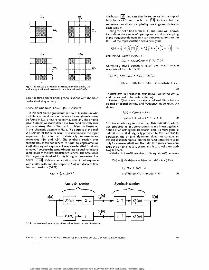
Most applications of QMFs to two or more dimensions have involved separable filters. A two-dimensional example i s illustrated in Fig. 1: The frequency spectrum i s split into low-pass, horizontal high-pass, vertical high-pass, and diag- onal high-pass sub-bands. The diagonal band contains mixed orientations.
Adelson er a/ . [I21 demonstrated that one could develop a non-separable decomposition based on hexagonally sym- metric QMFs, thereby achieving an orthogonal transform in which the all of the basis functions are localized in space, spatial frequency, and orientation. This approach to pyr- amid construction allows smooth spatial overlap between basis functions, and produces much better frequency tun- ing than does the blocked non-overlapping construction employed by Crettez and Simon [20] or Watson and Ahu- mada [21]. In the present paper we extend the Adelson et a/ . concepts; we describe methods for designing hexagonal QMFs, and we apply them to a variety of problems. We also
652
0018-9219/90/0400-0652$01,00 0 1990 IEEE
PROCEEDINGS OF THE IEEE, VOL. 78, NO. 4, APRIL 1990
Authorized licensed use limited to: IEEE Xplore. Downloaded on April 29, 2009 at 21:04 from IEEE Xplore. Restrictions apply.
.o X .....
Fig. 1. Idealized partition of the frequency domain by sep- arable application of two-band one-dimensional Q M F s .
describe three-dimensional generalizations with rhombic- dodecahedral symmetry.
REVIEW OF ONE DIMENSIONAL QMF CONCEPTS
In this section, we give a brief review of Quadrature Mir- ror Filters in one dimension. A more thorough review may be found in [22], or more recently, [23] or [24]. The original QMF problem was formulated as a two-band critically Sam- pled analysislsynthesis filter bank problem, as illustrated in the schematic diagram in Fig. 2. The purpose of the anal- ysis section of the filter bank i s to decompose the input sequence x[n] into two half-density representation sequences yo[n] and y1 [n]. The synthesis section then recombines these sequences to form an approximation i [ n ] to the original sequence. The system is called "critically sampled" because the sample input rate is equal tothe total sample rate of the intermediate sequences. The notation in the diagram i s standard for digital signal processing. The boxes indicate convolution of an input sequence with a filter with impulse response f i [n ] and discrete time Fourier transform (DTFT)
Fi(w) = fl[n]e-'"" n
Analysis section
A
The boxes indicate thatthe sequence i s subsampled by a factor of 2, and the boxes indicate that the sequence should be upsampled by insertingazero between each sample.
Using the definition of the DTFT and some well known facts about the effects of upsampling and downsampling in the frequency domain, one can derive equations for the DTFT of the representation sequences y,[n]:
Y;(w) = ; [F,( ; )x( ; ) + F,(; + .)x(; + .)I (1)
and the AIS system output i s
R(w) = Y0(2w)Go(w) + Y , ( 2 W ) G 7 ( W ) .
Combining these equations gives the overall system response of the filter bank:
fb) = ; [ F o b ) Go(w) + F1 (U) Cl (w)lX(w)
+ i [ F o ( ~ + *)Go(w) + F l ( W + T ) C ~ ( W ) ] X ( W + *). (2)
The first term is a linear shift-invariant (LSI) system response, and the second is the system aliasing.
The term QMF refers to a clever choice of filters that are related by spatial shifting and frequency modulation. We define
F&w) = Go(-w) = H(w)
Fl(w) = Gl(-w) = e/"H(-w + T ) (3)
for H(w) an arbitrary function of 0. This definition, which was proposed in [25], corresponds to the linear algebraic notion of an orthogonal transform, and is a more general definition than that originally provided by Croisier et al. In particular, the original definition does not contain an explicit spatial (temporal) shift factor and is therefore valid onlyfor even-length filters. The definition given above con- tains the original as a subcase, and is also valid for odd- length filters.
With thechoiceof filtersgiven in (3), equation (2) becomes
Synthesis section
2 . 1
2 . 1
Fig. 2. A two-band analysis/synthesis filter bank in one dimension.
653 SIMONCELLI AND ADELSON: NON-SEPARABLE EXTENSIONS OF QUADRATURE MIRROR FILTERS
Authorized licensed use limited to: IEEE Xplore. Downloaded on April 29, 2009 at 21:04 from IEEE Xplore. Restrictions apply.
1 2 . 1 ’ w - Yo, [nl 1 - Fl(@ - 2 . 1 w
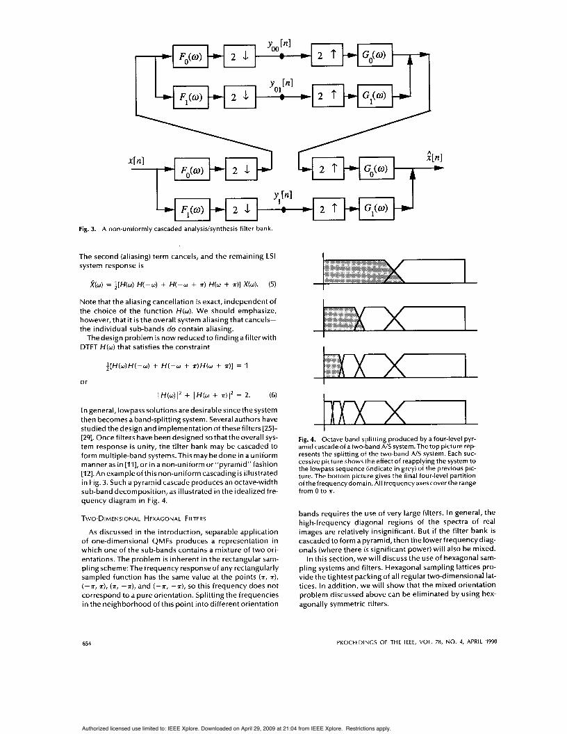
Fig. 3. A non-uniformly cascaded analysislsynthesis filter bank.
The second (aliasing) term cancels, and the remaining LSI system response is
2 ( w ) = i [ H ( w ) H(-w) + H( -w + K) H(w + 7r)l X(w). (5)
Note that the aliasing cancellation is exact, independent of the choice of the function /+(U). We should emphasize, however, that it i s the overall system aliasing that cancels- the individual sub-bands do contain aliasing.
The design problem i s now reduced to finding a filter with DTFT H(w) that satisfies the constraint
~ [ H ( w ) H ( - w ) + H ( - w + r ) H ( w + *)I = 1
or
(H(w)I2 + IH(w + * ) I 2 = 2. (6)
In general, lowpass solutions are desirable since the system then becomes a band-splitting system. Several authors have studied the design and implementation of these filters [25]- [29]. Once filters have been designed so that the overall sys- tem response i s unity, the filter bank may be cascaded to form multiple-band systems.This may bedone in a uniform manner as in [ I l l , or in a non-uniform or “pyramid” fashion [12]. An exampleof this non-uniform cascading i s illustrated in Fig. 3. Such a pyramid cascade produces an octave-width sub-band decomposition, as illustrated in the idealized fre- quency diagram in Fig. 4.
TWO-DIMENSIONAL HEXAGONAL FILTERS
As discussed in the introduction, separable application of one-dimensional QMFs produces a representation in which one of the sub-bands contains a mixture of two ori- entations. The problem is inherent in the rectangular sam- pling scheme: The frequency response of any rectangularly sampled function has the same value at the points (K, K), (-K, K), (K, -K), and (-K, -K), so this frequency does not correspond to a pure orientation. Splitting the frequencies in the neighborhood of this point into different orientation
........ ......... .................. ............. ............... x.x.:.:.:.:.: .................... ......... ......... .......... ......... ........ ......... ........ .......... ........ ......... ......... ......... ........... > ..........
L Fig. 4. Octave band splitting produced by a four-level pyr- amid cascade of a two-band A/S system. The top picture rep- resents the splitting of the two-band AIS system. Each suc- cessive picture shows the effect of reapplying the system to the lowpass sequence (indicate in grey) of the previous pic- ture. The bottom picture gives the final four-level partition ofthefrequencydomain.Al1 frequencyaxescoverthe range from 0 to K.
bands requires the use of very large filters. In general, the high-frequency diagonal regions of the spectra of real images are relatively insignificant. But if the filter bank is cascaded to form apyramid,then the lowerfrequencydiag- onals (where there is significant power) will also be mixed.
In this section, we will discuss the use of hexagonal sam- pling systems and filters. Hexagonal sampling lattices pro- vide the tightest packing of all regular two-dimensional lat- tices. In addition, we will show that the mixed orientation problem discussed above can be eliminated by using hex- agonally symmetric filters.
654 PROCEEDINGS OF THE IEEE, VOL. 78, NO. 4, APRIL 1990
Authorized licensed use limited to: IEEE Xplore. Downloaded on April 29, 2009 at 21:04 from IEEE Xplore. Restrictions apply.
e e 0
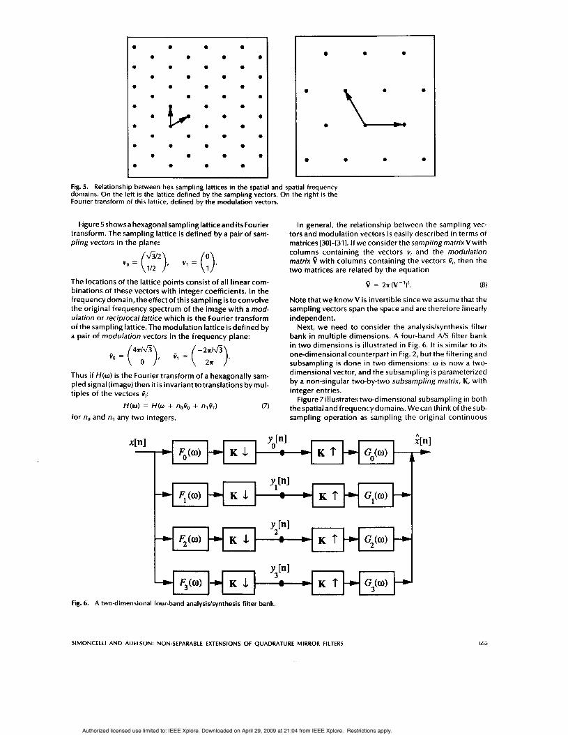
Figure5 showsa hexagonal sampling latticeand i ts Fourier transform. The sampling lattice is defined by a pair of sam- pling vectors in the plane:
The locations of the lattice points consist of al l linear com- binations of these vectors with integer coefficients. In the frequencydomain, theeffect of this sampling is toconvolve the original frequency spectrum of the image with a mod- ulation or reciprocal lattice which is the Fourier transform of the sampling lattice. The modulation lattice i s defined by a pair of modulation vectors in the frequency plane:
Fig. 5. Relationship between hex sampling lattices in the spatial and spatial frequency domains. On the left is the lattice defined by the sampling vectors. On the right is the Fourier transform of this lattice, defined by the modulation vectors.
4 6 h - 2 4 3 t o = ( ), t 1 = ( 2* ).
Thus if H ( o ) is the Fourier transform of a hexagonally sam- pled signal (image) then it i s invariant to translations by mul- tiples of the vectors ti:
H ( o ) = H(w + noto + nit,) (7) for no and nl any two integers.
In general, the relationship between the sampling vec- tors and modulation vectors i s easily described in terms of matrices [30]-[31]. If we consider the sampling matrix V with columns containing the vectors v, and the modulation matrix Q with columns containing the vectors t,, then the two matrices are related by the equation
Note that we know V is invertible since we assume that the sampling vectors span the space and are therefore linearly independent.
Next, we need to consider the analysislsynthesis filter bank in multiple dimensions. A four-band AIS filter bank in two dimensions is illustrated in Fig. 6. It i s similar to its one-dimensional counterpart in Fig. 2, but the filtering and subsampling i s done in two dimensions: w i s now a two- dimensional vector, and the subsampling i s parameterized by a non-singular two-by-two subsampling matrix, K, with integer entries.
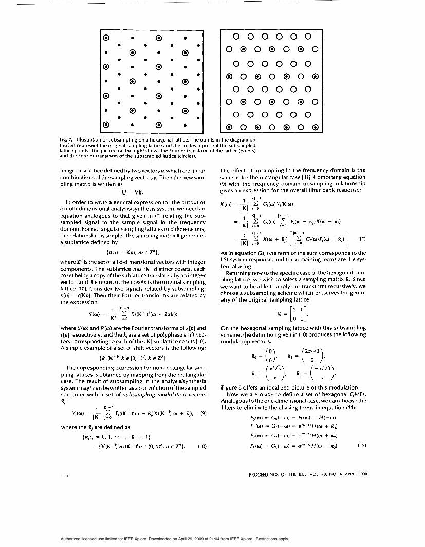
Figure 7 illustrates two-dimensional subsampling in both thespatial and frequencydomains. Wecan think of the sub- sampling operation as sampling the original continuous
S I M O N C E L L I A N D A D E L S O N : NON-SEPARABLE E X T E N S I O N S OF Q U A D R A T U R E M I R R O R FILTERS 655
Authorized licensed use limited to: IEEE Xplore. Downloaded on April 29, 2009 at 21:04 from IEEE Xplore. Restrictions apply.
~~
0 e 0 e
0 0 0 0 0
0 0 0 e 0 e
0 0 0 0 0
e e e e e e
e e e e e
0 e 0 e e 0
e e 0 0
0 0 0 e 0 0
e 0 0 0
0
0 0 0 0 0 0 0 0 0 0 0 0 0
0 0 0 0 0 0 0 0 0 0 0 0 0 0 0 0 0 0 0 0 0 0 0 0 0 0
0 0 0 0 0 0 0 0 0 0 0 0 0
Fig. 7. Illustration of subsampling on a hexagonal lattice. The points in the diagram on the left represent the original sampling lattice and the circles represent the subsampled lattice points. The picture on the right shows the Fourier transform of the lattice (points) and the Fourier transform of the subsampled lattice (circles).
image on a lattice defined by two vectors U, which are linear combinationsof the sampling vectors v,.Then the new sam- pling matrix i s written as
U = VK.
In order to write a general expression for the output of a multi-dimensional analysiskynthesis system, we need an equation analogous to that given in (1) relating the sub- sampled signal to the sample signal in the frequency domain. For rectangular sampling lattices in d dimensions, the relationship i s simple. The sampling matrix K generates a sublattice defined by
{ n : n = Km, m E Zd},
whereZdis the set of all d-dimensional vectors with integer components. The sublattice has I K( distinct cosets, each coset being acopyof the sublattice translated by an integer vector, and the union of the cosets is the original sampling lattice [IO]. Consider two signals related by subsampling: s[n] = r[Kn]. Then their Fourier transforms are related by the expression
1 I K I - 1 S(W) = - C R((K-')'(w - 2 ~ k , ) )
J K J I = O
where S(o) and R(w) are the Fourier transforms of s[n] and r[n] respectively, and the k, are a set of polyphase shift vec- tors corresponding to each of the I K I sublattice cosets [IO]. A simple example of a set of shift vectors is the following:
{k:(K-')'k E [0, k E Zd}.
The corresponding expression for non-rectangular sam- pling lattices i s obtained by mapping from the rectangular case. The result of subsampling in the analysiskynthesis system may then bewritten as a convolution of the sampled spectrum with a set of subsampling modulation vectors 4:
1 I K I - 1
Y,(o) = - c F,((K-')'w - K,)X((K-')'w + K]), (9) I K I / = o
where the K/ are defined as
{K/:/ = 0, 1, * . * , I K I - I }
= { V ( K - Y ~ : ( K - ~ ) ~ ~ E [o, qd, n E zd}. (IO)
The effect of upsampling in the frequency domain is the same as for the rectangular case [31]. Combining equation (9) with the frequency domain upsampling relationship gives an expression for the overall filter bank response:
As in equation (2), one term of the sum corresponds to the LSI system response, and the remaining terms are the sys- tem aliasing.
Returning now to the specific case of the hexagonal sam- pling lattice, we wish to select a sampling matrix K. Since we want to be able to apply our transform recursively, we choose a subsampling scheme which preserves the geom- etry of the original sampling lattice:
K = [: :]. On the hexagonal sampling lattice with this subsampling scheme, the definition given in (IO) produces the following modulatiqp vectors:
2 4 3 i i o = (;), Kl = (
)#
K, = (y), K3 = ( - 7r/& ~ ). Figure 8 offers an idealized picture of this modulation.
Now we are ready to define a set of hexagonal QMFs. Analogous to the one-dimensional case, we can choose the filters to eliminate the aliasing terms in equation (11):
(12)
656 PROCEEDINGS OF THE IEEE, VOL. 78, NO. 4, APRIL 1990
Authorized licensed use limited to: IEEE Xplore. Downloaded on April 29, 2009 at 21:04 from IEEE Xplore. Restrictions apply.

Oi'Y
.ox ....
.... . o x
Fig. 8. Illustration of the modulating effect of subsampling in the frequency domain. Assume that the sampled image has a spectrum bandlimited to the gray region in the upper left frequency diagram. Subsampling will modulate the spectrum to the gray regions in the other three diagrams. The resulting spectrum will be the sum of the four spectra.
where H is a function that i s invariant under negation of its argument, and the expressions 0's; indicates an inner product of the two vectors. As in equation (3), the filters are related by spatial shifting and frequency modulation. For the subsampling matrix we are using here, there are four sublattice cosets and therefore four distinct shifting vectors (including the zero vector). Two assignments of the si lead to system aliasing cancellation, and these two assignments are related by reflection through the origin. So without loss of generality, we choose the shifting vectors to be
&I2 - 6 1 2 s1 = ). s2 = (3. s3 = ( )
To see that the choice of filters in (12) forces cancellation of the aliasing terms, consider the aliasing response (the bracketed expression) in the second term ( j = 1) of equa- tion (11):
3
r = o G , ( o ) F , ( o + A,) = H ( - o ) H ( o + iil)
+ e-JW S 1 ~ ( o + iil) . e/(o+cl).slH(o + 2it1)
+ e - / O ' S Z H ( - " + k,) . e/'"''" H ( o + iil + K2)
+ e-/W'S"(-o + k3) . e/ ' "+ i? l " 'S1 H ( o + K1 + K3)
+ e/cl'SIH(-w + t , ) ~ ( w ) + e/21'SZ/i(-o + K,)H(W + K ~ ) + e / " 1 ' S 3 ~ ( - ~ + i i , ) ~ ( w + ic2)
= H ( - o ) H ( w + Kl)
= 0.
We have made use of the assumed symmetry of H ( o ) and the translation invariancedefined in equation (7).Theterms for j = 2 and j = 3 cancel in a similar manner.
After cancelling all of the aliasing terms in equation (II), the remaining LSI system response is
1 4 r = O
1 4 r = o
1 4 r = O
3
R(o) = - X ( 0 ) c C,(w)Fr(o)
3
= - X ( w ) c H ( - o + K,)H(w + K,)
= - X(0 ) c 1 H ( o + K,)I2.
3
(13)
As in onedimension,thealiasingcancellation isexact, inde- pendent of the choice of H(o), and the design problem is reduced to finding a filter with DTFT H ( o ) satisfying the constraint
3 c ( H ( o + k,)I2 = 4. (14)
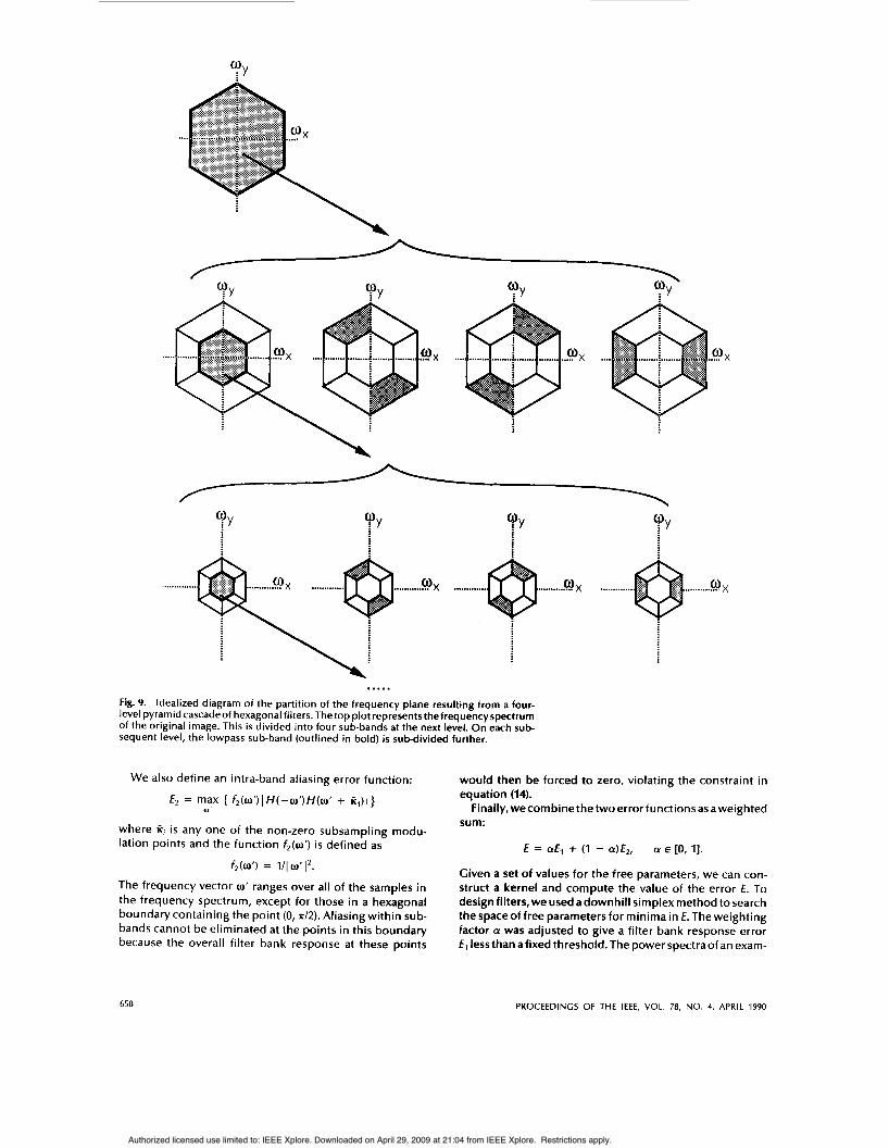
This is analogous to the one-dimensional equation (6). Again, a low-pass solution will producea band-splitting sys- tem which may be cascaded hierarchically to produce an octave bandwidth decomposition in two dimensions. An idealized illustration of this isgiven in Fig.9. Figureloshows the results of applying a hexagonal QMF bank to an image of a disk.
r = O
Hexagonal Filter Design
A "good" filter i s one that satisfies the constraint given in equation (14). In addition, many applications require that the sub-band images have a minimal amount of aliasing (as in the one-dimensional case, the individual subbands con- tain aliasing, although the overall system aliasing cancels). Our objective was to design filters with small regions of support that satisfy both of theseconstraints. In onedimen- sion, we found that a simple frequency-sampling design method produced high quality QMFs with small regions of support [25]. We have found that this method is suitable for multi-dimensional designs as well.
We begin by fixing the size of the hexagonal filter kernel and the sampling density in thefrequencydomain.The size of the kernel is measured in terms of the number of hex- agonal "rings" it contains. For example, a zero-ring filter containsonlyasingle impulse, and aone-ring filtercontains acenter impulse surrounded bya hexagonal ring of six more impulses. Due to the hexagonal symmetry, the free param- eters of the filter compriseawedge-shaped region covering approximately one twelfth of the kernel. These parameters completely specify the kernel.
We define a filter bank error function as the maximal deviation of the overall filter bank response given in equa- tion (13) from its ideal value:
where w ranges over the samples in the frequency spec- trum. The function fl (w) i s a frequency weighting function roughly matched to the sensitivity of the human visual sys- tem and the statistics of images:
fl(o) = Il(ol .
SlMONCELLl AND ADELSON: NON-SEPARABLE EXTENSIONS OF QUADRATURE MIRROR FILTERS 657
Authorized licensed use limited to: IEEE Xplore. Downloaded on April 29, 2009 at 21:04 from IEEE Xplore. Restrictions apply.
..... W X .... ..o x .... .w x
We also define an intra-band aliasing error function:
€2 = max { f , (w’) IH(-w’)H(w’ + i i , ) l}
where Ki is any one of the non-zero subsampling modu- lation points and the function f 2 ( 0 ’ ) i s defined as
U’
f,(w’) = 111 O’l2.
The frequency vector w‘ ranges over all of the samples in the frequency spectrum, except for those in a hexagonal boundary containing the point (0,7d2). Aliasing within sub- bands cannot be eliminated at the points in this boundary because the overall filter bank response at these points
..... Fig. 9. Idealized diagram of the partition of the frequency plane resulting from a four- level pyramid cascade of hexagonal filters. The top plot represents the frequency spectrum of the original image. This is divided into four sub-bands at the next level. On each sub- sequent level, the lowpass sub-band (outlined in bold) i s subdivided further.
would then be forced to zero, violating the constraint in equation (14).
Finally,wecombinethetwoerrorfunctionsasaweighted sum:
E = aE1 + (1 - 4 E 2 , a E [O, 11.
Given a set of values for the free parameters, we can con- struct a kernel and compute the value of the error €. To design filters, we used adownhill simplex method to search the spaceof free parameters for minima in E. The weighting factor a was adjusted to give a filter bank response error El less than a fixed threshold. The power spectra of an exam-
658 PROCEEDINGS OF THE IEEE, VOL. 78, NO. 4, APRIL 1990
Authorized licensed use limited to: IEEE Xplore. Downloaded on April 29, 2009 at 21:04 from IEEE Xplore. Restrictions apply.
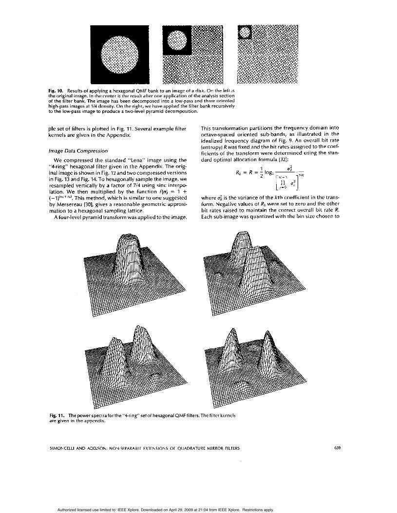
Fig. 10. Results of applying a hexagonal QMF bank to an image of a disk. On the left i s the original image. In the center i s the result after one application of the analysis section of the filter bank. The image has been decomposed into a low-pass and three oriented high-pass images at 1/4 density. O n the right, we have applied the filter bank recursively to the low-pass image to produce a two-level pyramid decomposition.
ple set of filters i s plotted in Fig. 11. Several example filter kernels are given in the Appendix.
Image Data Compression
We compressed the standard “Lena” image using the “4-ring” hexagonal filter given in the Appendix. The orig- inal image is shown in Fig. 12 and two compressed versions in Fig. 13 and Fig. 14. To hexagonally sample the image, we resampled vertically by a factor of 7/4 using sinc interpo- lation. We then multiplied by the function f[n] = 1 + ( - l ) ( n x + n y ) . This method, which i s similar to one suggested by Mersereau [30], gives a reasonable geometric approxi- mation to a hexagonal sampling lattice.
Afour-level pyramid transform was applied to the image.
This transformation partitions the frequency domain into octave-spaced oriented sub-bands, as illustrated in the idealized frequency diagram of Fig. 9. An overall bit rate (entropy) R was fixed and the bit rates assigned to the coef- ficients of the transform were determined using the stan- dard optimal allocation formula [32]:
where 4 is the variance of the k th coefficient in the trans- form. Negative values of i?k were set to zero and the other bit rates raised to maintain the correct overall bit rate R. Each sub-image was quantized with the bin size chosen to
Fig. 11. Thepower specrraforthe”4-ring”setof hexagonal QMFfiItersThefilter kernels are given in the appendix.
SlMONCELLl AND ADELSON: NON-SEPARABLE EXTENSIONS OF QUADRATURE MIRROR FILTERS 659
Authorized licensed use limited to: IEEE Xplore. Downloaded on April 29, 2009 at 21:04 from IEEE Xplore. Restrictions apply.
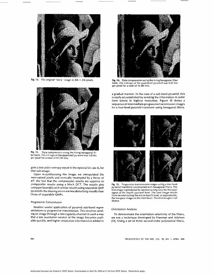
Fig. 12. The original "Lena" image at 256 x 256 pixels.
Fig. 13. Data compression using the 4-ring hexagonal fil- ter bank. The entropy of the quantized pyramid was 1.0 bits per pixel for a total of 65 536 bits.
give a first order entropy equal to the optimal bit rate Rk for that sub-image.
Upon re-synthesizing the image, we interpolated the zero-valued pixels and vertically resampled by a factor of 417. We feel that the compression results are superior to comparable results using a block DCT. The results also comparefavorablywith similar results using separable QMF pyramids: the aliasing errors are less disturbing visuallythan those of separable QMFs.
Progressive Transmission
Another useful application of pyramid sub-band repre- sentations i s progressive transmission. This involves send- ing an image through a low-capacity channel in such a way that a low resolution version of the image becomes avail- able quickly, and higher resolution information i s added in
Fig. 14. Datacompression using the4-ring hexagonal filter bank. The entropy of the quantized pyramid was 0.25 bits per pixel for a total of 16 384 bits.
a gradual manner. In the case of a sub-band pyramid, this i s easily accomplished by sending the information in order from lowest to highest resolution. Figure 15 shows a sequence of intermediate progressive transmission images for a four-level pyramid transform using hexagonal filters.
Fig. 15. Progressive transmission images using a four-level pyramid transform constructed with hexagonal filters. The first image is produced by reconstructing only the low-pass signal at the fourth pyramid level. The next image results from reconstructing the entire fourth level, or equivalently, the low-pass image on the third level. The final image i s not shown.
Orientation Analysis
To demonstrate the orientation selectivity of the filters, we use a technique developed by Freeman and Adelson [33]. Using a set of three second-order polynomial filters,
660 PROCEEDINGS OF THE IEEE, VOL. 78, NO. 4, APRIL 1990
Authorized licensed use limited to: IEEE Xplore. Downloaded on April 29, 2009 at 21:04 from IEEE Xplore. Restrictions apply.
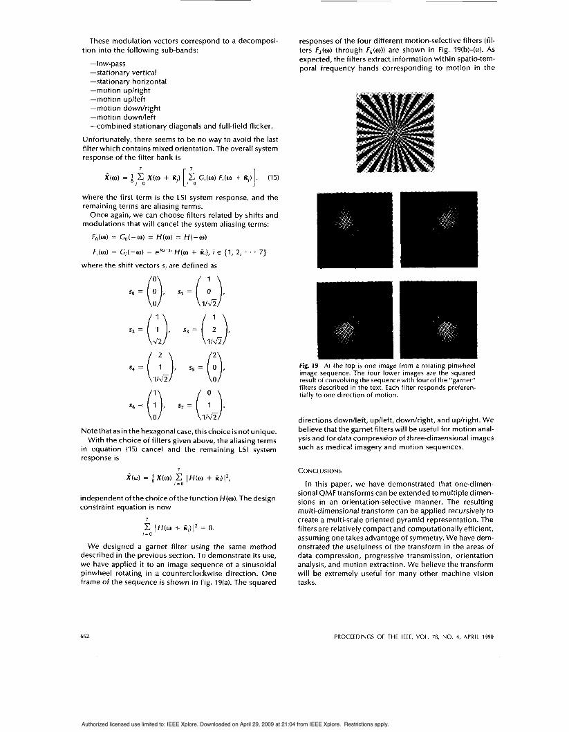
they extract the local orientation of the image at each pixel position.Although the hexagonal filters developed here are not second-order polynomials, they have similar frequency spectra and thus have approximately the same behavior when used in this fashion. Figure 17 shows a line drawing representationof the resultof applyingthetechniquetothe image of Einstein given in Figure 16. The line orientation corresponds to the local image orientation, and the line length corresponds to the degree of local anisotropy: Longer lines indicate that the image i s strongly oriented.
Fig. 16. Original image of Einstein.
c
Ill'
Fig. 17. An oriented line drawing of Albert Einstein, pro- duced by using linear combinations of the oriented hex- agonal filter outputs to measure the strength and orienta- tion of the local image anisotropy.
RHOMBIC DODECAHEDRAL FILTERS IN THREE DIMENSIONS
The extension of the concepts developed in the previous section to three dimensions i s fairly straightforward. Anal- ogous to the two-dimensional hexagonal case, we choose a periodic sampling lattice which corresponds to the densest packing of spheres in three dimensions. This i s the
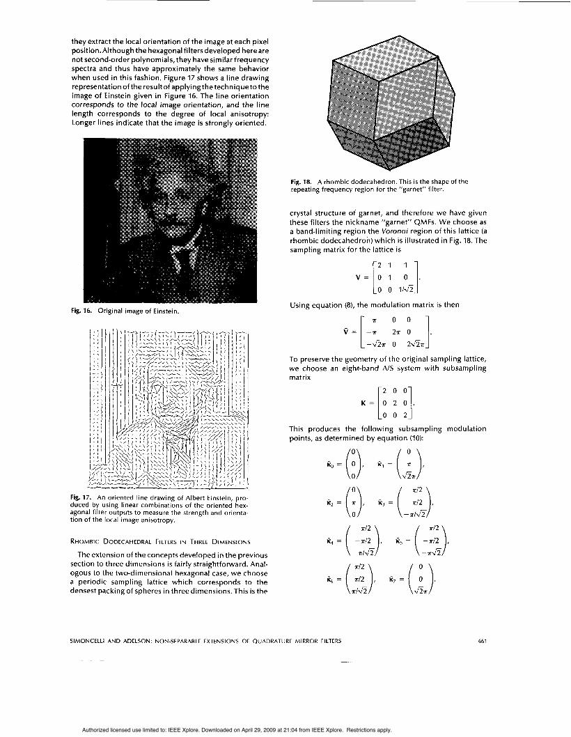
Fig. 18. A rhombic dodecahedron. This is the shape of the repeating frequency region for the "garnet" filter.
crystal structure of garnet, and therefore we have given these filters the nickname "garnet" QMFs. We choose as a band-limiting region the Voronoi region of this lattice (a rhombic dodecahedron) which is illustrated in Fig. 18. The sampling matrix for the lattice i s
v = [2 0 1 1. 0 0 II&
Using equation (8), the modulation matrix i s then
0 0
2* 0 1. -&* 0 2 a *
To preserve the geometry of the original sampling lattice, we choose an eight-band AIS system with subsampling matrix
K = 0 2 0 . [: : :1 This produces the following subsampling modulation points, as determined by equation (IO):
SlMONCELLl AND ADELSON: NON-SEPARABLE EXTENSIONS OF QUADRATURE MIRROR FILTERS
T ~~
661
Authorized licensed use limited to: IEEE Xplore. Downloaded on April 29, 2009 at 21:04 from IEEE Xplore. Restrictions apply.
These modulation vectors correspond to a decomposi-
-low-pass -stationary vertical -stationary horizontal -motion uplright -motion uplleft -motion dowdright -motion downlleft -combined stationary diagonals and full-field flicker.
Unfortunately, there seems to be no way to avoid the last filter which contains mixed orientation. The overall system response of the filter bank i s
tion into the following sub-bands:
7 1 R(w) = X(w + K,) c G,(w) F,(w + ii,) . (15)
where the first term i s the LSI system response, and the remaining terms are aliasing terms.
Once again, we can choose filters related by shifts and modulations that will cancel the system aliasing terms:
/ = 0 Lo
Fo(w) = Go(-w) = H(w) = H ( - w )
F,(w) = G,(-w) = e/o'si H(w + K,), i E {I, 2,
where the shift vectors s, are defined as
so = (i), s1 = ( s2 = (i). s3 = ( s4 = (
s5 = (i),
. . . 7)
Note that as in the hexagonal case, this choice i s not unique. With the choice of filters given above, the aliasing terms
in equation (15) cancel and the remaining LSI system response is
7
i ( u ) = Q X(0) c 1 H(w + k,)I*, ,=o
independent of thechoiceof the function H(w).The design constraint equation is now
7
IH(w + KJI2 = 8. ,=o
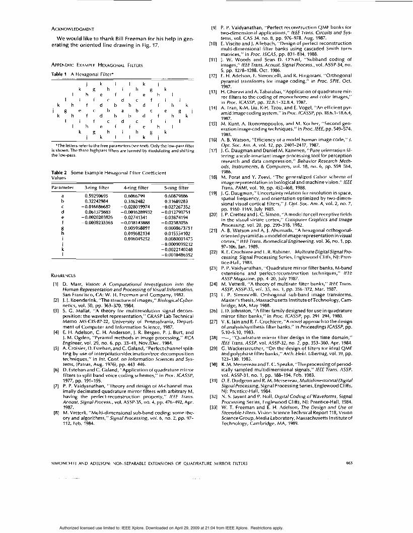
We designed a garnet filter using the same method described in the previous section. To demonstrate its use, we have applied it to an image sequence of a sinusoidal pinwheel rotating in a counterclockwise direction. One frame of the sequence is shown in Fig. 19(a). The squared
responses of the four different motion-selective filters (fil- ters F3(w) through F,(w)) are shown in Fig. 19(b)-(e). As expected, the filters extract information within spatio-tem- poral frequency bands corresponding to motion in the
Fig. 19 At the top i s one image from a rotating pinwheel image sequence. The four lower images are the squared result of convolving the sequence with four of the "garnet" filters described in the text. Each filter responds preferen- tially to one direction of motion.
directions downlleft, uplleft, downlright, and uplright. We believe that the garnet filters will be useful for motion anal- ysis and for data compression of three-dimensional images such as medical imagery and motion sequences.
CONCLUSIONS
In this paper, we have demonstrated that one-dimen- sional QMF transforms can be extended to multiple dimen- sions in an orientation-selective manner. The resulting multi-dimensional transform can be applied recursively to create a multi-scale oriented pyramid representation. The filters are relatively compact and computationally efficient, assuming one takes advantage of symmetry. We have dem- onstrated the usefulness of the transform in the areas of data compression, progressive transmission, orientation analysis, and motion extraction. We believe the transform will be extremely useful for many other machine vision tasks.
662 PROCEEDINGS OF THE IEEE, VOL. 78, NO. 4, APRIL 1990
Authorized licensed use limited to: IEEE Xplore. Downloaded on April 29, 2009 at 21:04 from IEEE Xplore. Restrictions apply.
ACKNOWLEDGMENT
W e would l ike to thank Bi l l Freeman fo r his he lp in gen- erat ing t h e or iented l ine drawing in Fig. 17.
APPENDIX: EXAMPLE HEXAGONAL FILTERS
Table 1 A Hexagonal Filter* ~
j k l l k j k g h i h g k
l h e f f e h l l i f c d c f i l
k h f d b b d f h k j g e c b a b c e g j
k h f d b b d f h k l i f c d c f i l
l h e f f e h l k g h i h g k
j k l l k j
*The letters refer to the free parameters (see text). Only the low-pass filter is shown. The three highpass filters are formed by modulating and shifting the low-pass.
Table 2 Some Example Hexagonal Filter Coefficient Values
Parameter 3-ring filter 4-ring filter 5-ring filter
a b
d e f g h
i k I
C
I
0.59290695 0.6066799 0.32242984 0.31 62482
- 0.01 6686682 -0.061579883 -0.0016289932 -0.0020203826 -0.02741341 -0.0038235565 -0.038143888
- 0.005958891 0.019682134 0.01 6045252
- 0.02801 9974
0.60879886 0.31689283
-0.027267352 - 0.01 2790751 -0.03874194 -0.02383056
0.0008673751 0.01 55541 02 0.0080001 475
- 0.0009099232 - 0.0022140248 -0.001 0486352
REFERENCES D. Marr, Vision: A Computational Investigation into the Human Representation and Processing o f Visual Information. San Francisco, CA: W. H. Freeman and Company, 1982. J. J. Koenderink, “The structure of images,” BiologicalCyber- netics, vol. 50, pp. 363-370, 1984. S. G. Mallat, “A theory for multiresolution signal decom- position: the wavelet representation,” GRASP Lab Technical Memo MS-CIS-87-22, University of Pennsylvania, Depart- ment of Computer and Information Science, 1987. E. H. Adelson, C. H. Anderson, J. R. Bergen, P. J. Burt, and J. M. Ogden, “Pyramid methods in image processing,” RCA Engineer, vol. 29, no. 6, pp. 33-41, Nov./Dec. 1984. A. Croisier, D. Esteban, and C. Galand, “Perfect channel split- ting by use of interpolationldecimationltree decomposition techniques,” in Int. Conf. on lnformation Sciences and Sys- tems, (Patras, Aug. 1976), pp. 443-446. D. Esteban and C. Galand, ”Application of quadrature mirror filters to split band voice coding schemes,” in Proc. ICASSP,
P. P. Vaidyanathan, “Theory and design of M-channel max- imally decimated quadrature mirror filters with arbitrary M, having the perfect-reconstruction property,” I€€€ Trans. Acoust. Signal Process., vol. ASSP-35, no. 4, pp. 476-492, Apr. 1987. M. Vetterli, “Multi-dimensional sub-band coding: some the- ory and algorithms,” Signal Processing, vol. 6, no. 2, pp. 97- 112, Feb. 1984.
1977, pp. 191-195.
P. P. Vaidyanathan, ”Perfect reconstruction QMF banks for two-dimensional applications,” I€€€ Trans. Circuits and Sys- tems, vol. CAS 34, no. 8, pp. 976-978, Aug. 1987. E. Viscito and J. Allebach, “Design of perfect reconstruction multi-dimensional filter banks using cascaded Smith form matrices,” in Proc. ISCAS, pp. 831-834, 1988. J. W. Woods and Sean D. O‘Neil, “Subband coding of images,” /€E€ Trans. Acoust. Signal Process., vol. ASSP-34, no.
E. H. Adelson, E. Simoncelli, and R. Hingorani, “Orthogonal pyramid transforms for image coding,” in Proc. SPIE, Oct. 1987. H. Gharavi and A. Tabatabai, ”Application of quadrature mir- ror filters to the coding of monochrome and color images,” in Proc. ICASSP, pp. 32.8.1-32.8.4, 1987. A. Tran, K-M. Liu, K-H. Tzou, and E. Vogel, ”An efficient pyr- amid image coding system,” in Proc. ICASSP, pp. 18.6.1-18.6.4, 1987. M. Kunt, A. Ikonomopoulos, and M. Kocher, “Second gen- eration image-coding techniques,” in Proc. /E€€, pp. 549-574, 1985. A. B. Watson, ”Efficiency of a model human image code,” 1. Opt. Soc. Am. A, vol. 12, pp. 2401-2417,1987. J. G. Daugman and Daniel M. Kammen, ”Pure orientation fil- tering: a scale-invariant image-processing tool for perception research and data compression,” Behavior Research Meth- ods, Instruments, & Computers, vol. 18, no. 6, pp. 559-564, 1986. M. Porat and Y. Zeevi, “The generalized Cabor scheme of image representation in biological and machine vision,” / €€E Trans. PAMI, vol. IO, pp. 452-468, 1988. J . G. Daugman,” Uncertainty relation for resolution in space, spatial frequency, and orientation optimized by two-dimen- sional visual cortical filters,”). Opt. Soc. Am. A, vol. 2, no. 7,
J. P. Crettez and J. C. Simon, “A model for cell receptive fields in the visual striate cortex,” Computer Graphics and Image Processing, vol. 20, pp. 299-318, 1982. A. B. Watson and A. J. Ahumada, “A hexagonal orthogonal- oriented pyramid as a model of image representation in visual cortex,” /€E€ Trans. BiomedicalEngineering, vol. 36, no. 1, pp. 97-106, Jan. 1989. R. E. Crochiere and L. R. Rabiner. MultirateDigifalSignalPro- cessing. Signal Processing Series, Englewood Cliffs, NJ: Pren- tice-Hall, 1983. P. P. Vaidyanathan, “Quadrature mirror filter banks, M-band extensions and perfect-reconstruction techniques,” I€€€ ASSP Magazine, pp. 4-20, July 1987. M. Vetterli, “A theory of multirate filter banks,” / €€E Trans. ASSP, ASSP-35, vol. 35, no. 3, pp. 356-372, Mar. 1987. E. P. Simoncelli. Orthogonal sub-band image transforms. Master’s thesis, Massachusetts Institute of Technology, Cam- bridge, MA, May 1988. J. D. Johnston, “A filter family designed for use in quadrature mirror filter banks,” in Proc. ICASSP, pp. 291-294, 1980. V. K. lain and R. E. Crochiere, ”A novel approach to the design of analysislsynthesis filter banks,” in Proceedings ICASSP, pp. 5.10-5.10, 1983. - , “Quadrature mirror filter design in the time domain,” /€E€ Trans. ASSP, vol. ASSP-32, no. 2, pp. 353-360, Apr. 1984. G. Wackersreuther, ”On the design of filters for ideal QMF and polyphase filter banks,”Arch. € lek Ubertrag, vol. 39, pp. 123-130, 1985. R. M. Mersereau and T. C. Speake, “The processing of period- ically sampled multidimensional signals,” /€€€ Trans. ASSP, vol. ASSP-31, no. 1, pp. 188-194, Feb. 1983. D. E. Dudgeon and R. M. Mersereau, MultidimensionalDigital SignalProcessing, Signal Processing Series, Englewood Cliffs, NJ: Prentice-Hall, 1984. N. S. Jayant and P. NOH, Digital Coding o f Waveforms, Signal Processing Series, Englewood Cliffs, NJ: Prentice-Hall, 1984. W. T. Freeman and E. H. Adelson, The Design and Use o f Steerable Filters. Vision Science Technical Report 118, Vision Science Group, Media Laboratory, Massachusetts Instituteof Technology, Cambridge, MA, 1989.
5, pp. 1278-1288, Oct. 1986.
pp. 1160-1169, July 1985.
SIMONCELLI AND ADELSON: NON-SEPARABLE EXTENSIONS OF QUADRATURE MIRROR FILTERS
1 -
663
Authorized licensed use limited to: IEEE Xplore. Downloaded on April 29, 2009 at 21:04 from IEEE Xplore. Restrictions apply.
Eero P. Simoncelli (Student Member, IEEE) received the B.S. degree in physics, summa cum laude, from Harvard University, Cam- bridge, MA, in 1984, and the M.S. degree from the Massachusetts Institute of Tech- nology, Cambridge, MA, in 1988.
His research experience includeswork in neural networks at Bell Laboratories, done after graduating from Harvard, followed by work in mathematics at Cambridge Uni- versity, England, as a Knox Fellowship
Edward H. Adelson (Member, IEEE) received the B.A. degree in physics and philosophy from Yale University, New Haven, CT, in 1974, and the Ph.D. degree in experimental psychology from the University of Michi- gan, Ann Arbor, in 1979.
He is an Associate Professor of Vision Sci- ence at the Media Laboratory and the Department of Brain and Cognitive Science of the Massachusetts Institute of Technol- ogy, Cambridge, MA. He has published
recipient. His M.S. thesis focused-on sub-band transform repre- sentation of images.
widely on various topics-in human psychophysics, computational vision, and image processing.
Dr. Adelson is a Fellow of the Optical Society of America, and a recipient of the Adolph Lomb Medal.
Mr. Simoncelli i s a member of Phi Beta Kappa.
664 PROCEEDINGS OF THE IEEE, VOL. 78, NO. 4, APRIL 1990
Authorized licensed use limited to: IEEE Xplore. Downloaded on April 29, 2009 at 21:04 from IEEE Xplore. Restrictions apply.