Embed Size (px)
Citation preview

-A187 766 REFERENCE STANDARDS FOR NONDESTRUCTIVE TESTS(U) ARMY 1/1ARMAMENT RESEARCH DEVELOPMENT AND ENGINEERING CENTERDOVER NJ PRODUCT AS SURANCE DIRECTORATE H HARTMANN
UNCLASSIFIED OCT 87 ARPAD-TR-8 DT6 F/G i/6 IL
EllllEllllllEEIElllEElhEllllEI

1.25 1. 6
M, k Py RE C 'N TF T HART

(0 IAD
AD-E401 74700I-.I FILE cOPYTECHNICAL REPORT ARPAD-TR-87006
REFERENCE STANDARDS FOR NONDESTRUCTIVE TESTS
MELECTE J
HENRY HARTMANN a O "D7 ~
OCTOBER 1987
U. S. ARMY ARMAMENT RESEARCH, DVlOPMENT AND E CENTER
PRODUCT ASSURANCE DIRECTORATEUS ARMY
CHEMICAL COMMAND PICATINNY ARSENAL, NEW JERSEYARMAMENT ROE CENTER
APPROVED FOR PUBLIC RELEASE: DISTRIBUTION IS UNLIMITED.
S. .

The views, opinions, and/or findings contained inthis report are those of the author(s) and shouldnot be construed as an official Department of theArmy position, policy, or decision, unless sodesignated by other documentation.
The citation in this report of the names ofcommercial firms or commercially availableproducts or services does not constitute officialendorsement by or approval of the U.S.Government.
Destroy this report when no longer needed by anymethod that will prevent disclosure of contents orreconstruction of the document. Do not return tothe originator.
o*.
['..
6:

UNCLASSIFIEDSECURITY CLASSIFICATION OF THIS EPO TDCM NAINPG
REPORT DOCUMENTATION PAGE
In. REPORT SECURITY CLASSIFICATION lb. RESTRICTIVE MARKINGS
UNCLASSIFIED29. SECURITY CLASSIFICATION AUTHORITY 3. DISTRIBUTION/AVAILABILITY OF REPORT
2b. DECLASSIFICATION/DOWNGRADING SCHEDULE Approved for public release; distribution is unlimited.
4. PERFORMING ORGANIZATION REPORT NUMBER) 5. MONITORING ORGANIZATION REPORT NUMBER)
Technical Report ARPAD-TR-870066a. NAME OF PERFORMING ORGANIZATION 16b. OFFICE SYMBOL 7a. NAME OF MONITORING ORGANIZATIONARDEC, PAD ITechnology Office AMSMC-QAH-T(D)
6c. ADDRESS (CITY, STATE, AND ZIP CODE) 7b. ADDRESS (CITY, STATE, AND ZIP CODE)
Picatinny Arsenal, NJ 07806-5000
Ba. NAME OF FUNDING, SPONSORING 8b. OFFICE SYMBOL 9. PROCUREMENT INSTRUMENT IDENTIFICATION NUMBER
ORGANIZATIOS ARDEC, IMDSTINFO Br SMCAR-iMI-I
8c. ADDRESS (CITY, STATE, AND ZIP CODE) 10. SOURCE OF FUNDING NUMBERS
PROGRAM PROJECT NO. TASK NO. WORK UNIT
Picatinny Arsenal, New Jersey 07806-5000 ELEMENT NO. ACCESSION NO.
11. TITLE (INCLUDE SECURITY CLASSIFICATION)
REFERENCE STANDARDS FOR NONDESTRUCTIVE TESTS12. PERSONAL AUTHOR(S)
Henry Hartmann13a. TYPE OF REPORT 13b. TIME COVERED 14. DATE OF REPORT (YEAR, MONTH, DAY) 15. PAGE COUNT
I FROM - TO October 1987 4016. SUPPLEMENTARY NOTATION
17. COSATI CODES 16/SUBJECT TERMS (CONTINUE ON REVERSE IF NECESSARY AND IDENTIFY BY BLOCK NUMBER)
FIELD GROUP SUB-GROUP Reference Standards, Inspection, Cracks /
Nondestructive tests Flaws Defects __---_
19. ABSTRACT (CONTINUE ON REVERSE IF NECESSARY AND IDENTIFY BY BLOCK NUMBER)
Reference standards are the prime element of nondestructive tests. Standards contain the flaw or asimulated representation that is being sought, such as cracks, and these flaws are in a geometry thatsimulates the parts to be tested. This report emphasizes cracks in metal parts, how to calculate cracksizes, and how to simulate cracks in reference standards(, A, V
20. DISTRIBUTION/AVAILABILITY OF ABSTRACT 21. ABSTRACT SECURITY CLASSIFICATION
0 UNCLASSIFIED/UNLIMITED E'J SAME AS RPT. DTIC USERSi UNCLASSIFIED22s. NAME OF RESPONSIBLE INDIVIDUAL 22b. TELEPHONE (INCLUDE AREA CODE) 22c. OFFICE SYMBOL
I HAZNEDARI 201 724-3316 SMCAR-IMI-1
DD FORM 1473, 84 MAR UNCLASSIFIED
SECURITY CLASSIFICATION OF THIS PAGE
.'j

CONTENTS
Page
Introduction 1
Philosophy 2
Nondestructive Tests 3
Proof Tests 3Liquid Penetrant Tests 5Magnetic Particle Tests 7Radiography Tests 8Ultrasonic Tests 9Eddy Current Tests Using Probe Coils Only 17Magnetic Flux Leakage Tests 19Accumulation Leakage Tests 20
Lengths of Slots 22
Conclusions 23
References 29
Glossary 31
Distribution List 35
Accesion For
N TIS CRA&IDT'IC TAB Li
....................................................... ..... ....................
ii
CowAfw
S

NONDESTRUCTIVE TESTS
Proof Tests
Proof testing is the oldest form of nondestructive testing; all of the acceptable partsare perserved. Chain and rope are subject to proof test loads to verify that they aresafe for use at lower "rated" loads. A reference standard normally is not used in thesesimple pull tests. What is used is a master load cell gauge red-lined at the desiredstrength. This value of strength has been determined by prior destructive tests of soundas well as purposely weakended rope and chain. The literature accompanying ropeand chain will often designate the rated load and, for better quality material, may revealthe proof test load.
Proof test loads have minimum values, applying at least the minimum designatedvalue. The accuracy of the load cell gauge used to measure minimum proof test pullshould be at least 0.1% of the proof strength value. Therefore, a 1,000 kilogram prooftest load would require a load cell graduated in increments of kilograms and accurate towithin one kilogram at and around the 1,000 kilogram value. Unless constructed forcontinuous use, such a gauge would be used only to check the accuracy of the pullingmechanism.
There was a time when barrels for cannon had to be cast. Pistols and rifles, beingmuch smaller, were made from wrought iron. However, the larger cannon barrels weretoo big to be hammered or rolled into shape; therefore, they were cast. To check forsoundness of the cast metal,,all guns were (and are still) proof tested., Extra propellant(a proof charge) is used to assure that all gun barrels have the extra strength neededfor safe use.
Data on proof test pressures can be gathered in laboratories by special guagesincorporated into modified gun tubes. Pressure transducers provide a pressure-versus-time trace. Copper crush gauges, using copper balls sandwiched betweenhardened pistons and anvils, provide peak pressure measurement by the size of theflats squeezed into the copper balls.
Expanding Mandrel
For cylindrically-shaped parts containing at least one open end, a mechanicallyexpanding mandrel is a relatively cheap and rapid method for proof testing the hoopstrength of each part. Expanding mandrels are generally designed with a conicalwedge over which tapered segments are held in place. As the conical wedge ad-vances, the tapered segments expand outward radially.
3

For use in manufacturing, the conical wedge of an expanding mandrel willgenerally have a fixed stroke (i.e., the mechanism driving the conical wedge will bottomagainst a fixed stop). A fixed stroke is not acceptable for nondestructive tests. For NDTpurposes where the hoop strength of a part is being evaluated, a fixed peak force drivesthe conical wedge until the resistance to expansion stops all movement. Normally, thistest will leave a slight permanent deformation in the part. Parts of inadequate strengthwill permit excessive expansion. The conical wedge will pass the normal limit of move-ment and trigger a reject alarm. The rejected part will have greater permanent deforma-tion, perferably being of unusable size. Sometimes the parts will fail with a snappingsound while at other times a failure will be quiet.
The repeatability of the constant peak force that moves the expanding mandrelis important. Usually, compressed air drives a piston in a pneumatic cylinder. Linepressure in compressed air lines can vary substantially. Therefore, a precision airregulator feeding an oversized air cylinder will be needed for a constant-air-pressure,constant-force design. An oversized air cylinder will be needed as the working airpressure must be somewhat less than the minimum line pressure that could occur.Hydraulics can also be used as a prime mover.
Variations in the applied stress from an expanding mandrel can be measuredby use of a strain gauged "good" part.
Good and reject reference standards consisting of sound and weakened partscan demonstrate the effectiveness of an expanding mandrel test.
Hydrostatic
Hydrostatic proof testing presents more of a safety hazard to operators thanexpanding mandrel tests. Weak parts often burst into pieces with a loud bang, andoperators must be protected from flying fragments. For example: 155-mm M549artillery warhead bodies were 100% hydrotested. The reason for the hydrotest was thatthe warhead bodies were made from a somewhat brittle HF-1 high fragmentation alloysteel. The hydrotest consisted of applying :n internal pressure of 15,000 psi minimum,holding the pressure for 15 seconds, and then releasing the pressure. Of the manywarhead body failures that occurred, most occurred during the buildup in pressure. The
,,0 rejects would burst amidst a great racket of rattling fragments and flying spray. A fewwarheads burst during the peak pressure holding period, and a few had failed hydrotestby leaking so badly that peak pressure could not be attained.
."rB

INTRODUCTION
This technical report is written for people familiar with nondestructive tests. Defini-tions of key technical words and phrases are listed in the glossary. The definitions ofkey technical words and phrases are listed in the glossary. The definitions are specificto the particular use of the words or phrases in this report. Use of the glossary can aidin a better understanding of this report.
Short cuts need not be desireable. Following is a typical response from a contrac-tor when asked, "Where are the reference standards?" "What do I need a referencestandard for? My nondestructive test (NDT) equipment is working just fine. Every oncein a while it even rejects a part. So what do I need a reference standard for?"
There are a few simple NDTs such as some strength or proof tests, wherereference standards are not needed. For most NDTs, the use of reference standardsare essential for accurately setting-up NDT equipment to achieve adequate sensitivity.If referencing cracks, a proper standard containing a simulated or real crack of knownsize will permit proper adjustment of the NDT equipment so that cracks of a designatedsize or larger will be rejected. Reference standards provide a direct correlation betweenNDT equipment and the size of sought defects.
Reliable sensitivity is the most important factor in the successful use of nondestruc-tive testing. If the NDT method has the ability to detect the presence of small defectsthat can unacceptably weaken the part being tested, and the NDT can repeatably detectsimilar small defects over and over again, then the method is judged to have adequatereliability of sensitivity for the application.
Reference standards also permit control of accuracy on the measurement of thesize of sought defects. Should something alter the established sensitivity of detection,use of a reference standard will permit evaluation of any change in detection sensitivityand will permit proper adjustment.
Emphasis in this report is on cracks. There are many other types of discontinutiesthat can weaken or make parts unacceptable; however, cracks in high strength metalparts have been found to be a serious menance.
The examples used in this report often cite U.S. Army munitions. The U.S. Armyhas invested heavily in NDT to assure that its ammunition is safe Nondestructivetesting has been a major influence in the increased performance of the U.S. Army'sartillery weapon systems while maintaining the same levels of safety.
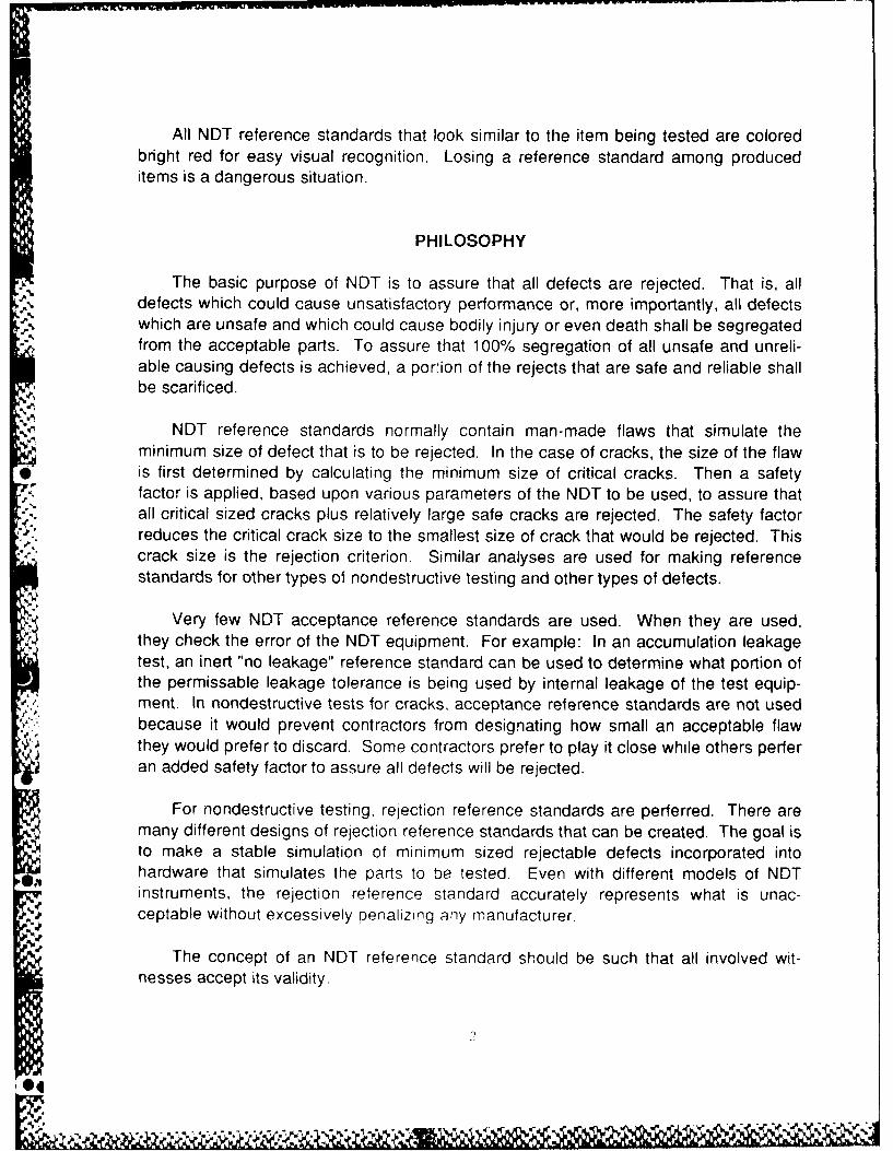
All NDT reference standards that look similar to the item being tested are coloredbright red for easy visual recognition. Losing a reference standard among produceditems is a dangerous situation.
PHILOSOPHY
The basic purpose of NDT is to assure that all defects are rejected. That is, alldefects which could cause unsatisfactory performance or, more importantly, all defects
J., which are unsafe and which could cause bodily injury or even death shall be segregatedfrom the acceptable parts. To assure that 100% segregation of all unsafe and unreli-able causing defects is achieved, a portion of the rejects that are safe and reliable shallbe scarificed.
NDT reference standards normally contain man-made flaws that simulate theminimum size of defect that is to be rejected. In the case of cracks, the size of the flaw
* is first determined by calculating the minimum size of critical cracks. Then a safetyfactor is applied, based upon various parameters of the NDT to be used, to assure thatall critical sized cracks plus relatively large safe cracks are rejected. The safety factorreduces the critical crack size to the smallest size of crack that would be rejected. Thiscrack size is the rejection criterion. Similar analyses are used for making referencestandards for other types of nondestructive testing and other types of defects.
Very few NDT acceptance reference standards are used. When they are used,they check the error of the NDT equipment. For example: In an accumulation leakagetest, an inert "no leakage" reference standard can be used to determine what portion ofthe permissable leakage tolerance is being used by internal leakage of the test equip-ment. In nondestructive tests for cracks, acceptance reference standards are not usedbecause it would prevent contractors from designating how small an acceptable flawthey would prefer to discard. Some contractors prefer to play it close while others perferan added safety factor to assure all defects will be rejected.
For nondestructive testing, rejection reference standards are perferred. There aremany different designs of rejection reference standards that can be created. The goal isto make a stable simulation of minimum sized rejectable defects incorporated intohardware that simulates the parts to be tested. Even with different models of NDTinstruments, the rejection reference standard accurately represents what is unac-ceptable without excessively penalizing any manufacturer.
The concept of an NDT reference standard should be such that all involved wit-nesses accept its validity.
0NI

During this hydrotest, the operator was busy loading and unloading test sta-tions. Little time was left for analysis. Automatic controls (red light or green light)revealed whether or not the projectile body had successfully passed hydrotest. When ared light was encountered, the peak holding pressure of 15,000 psi had not beenreached. Either the warhead body had a leak or the "0" ring hydraulic fluid seal againstthe nose of the warhead body was leaking. The protective steel shroud that retainedflying fragments masked visual observation of where the leakage was coming from.
The red light-operator interface, turned out to be a crucial weakness for thishydrotest. A warhead body with a huge crack through the wall that ran three-quarters ofthe way around the body was accepted by an operator and wound up in a loading plant.Fortunately, an alert loading plant operator saw the crack and rejected the warheadbody. The problem was human error. A busy operator forgot the warhead body cameout of a red-lighted station and failed to reject the cracked warhead body. The solution
2 to this problem should have been to remove the decision-making action of acceptanceversus rejection from the operator.
Even though no reference standards were used in this hydrotest, two couldhave been used. A no-leakage reference standard could have quickly determined theadequacy of suspect "0" ring seals. A gross-leakage reference standard could haveassured that all stations were rejecting cracked warhead bodies that leak.
Liquid Penetrant Tests
No matter how deep the defect, all that liquid penetrant can reveal is whether or nota defect occurs in a surface. Unless the indication is large, there are few clues as to thedepth of a defect. As a result, rejection is based solely upon the revealed surfaceimage of a defect.
Plugs
Circular cracks can be simulated by press-fitting plugs into the metal to betested. Plugs can be easily fitted into sheet metal as thin as 1 1/2 mm (0.06 in.). Metalfrom the same sheet should be used for the plug. Plugging can be accomplished by
,. reaming a fine finished hole, turning a slightly oversized plug from a small piece of thesame metal, aligning plug over hole, and pressing together. Care must be taken tomake adjacent sides absolutely flush with one another. Usually, a final polish or grindwill be needed for an absolute flush fit all around on both sides.
)

Plugs can be inserted into all kinds of part geometry. When properly done, theplugs are not obvious. They should be located where defects tend to cause greatweakness and where defects are not easy to see.
Size of the plugs should be small. For example: if the reject criterion is anycrack greater than 2 mm (0.08 in.) in length, then the plugs should be 2 mm in diameter.
The advantage of a plug simulating a crack is that the simulation is in all
directions on a surface. Any directional bias in the revelation of cracks (possibly caused"-K by rinsing) will be revealed by a 360-degree crack.
Quench Cracks
Natural cracks can be created by quenching. Localized heating just short ofmelting and then rapid quenching in frigid water can induce quench cracks in higherstrength, lower ductility metals. The cracks tend to occur around the hot spot.
the..With just a few cracks in known locations, it would be easy to observe a loss inthe sensitivity of revelation of a liquid penetrant. Special quench processes to achievedesired distributions of cracks are feasible.
Plugs also provide the versatility of incorporating natural cracks of known sizeinto a reference standard. The natural cracks could be made to the depth and lengthrequired and then transferred, within a plug, to a reference standard. The orientation ofa crack within a plug would be under complete control.
Quench cracked blocks and rings are commercially available in limited typesand sizes of metals. Unless the metal to be tested is commercially available in the formof crack standards, it would be better to make your own quench crack referencestandards.
Magnetic particle testing quench crack rings, if of the same metal, can be usedas liquid penetrant reference standards.
After usage to reveal the sensitivity of a liquid penetrant, the reference stand-ards must be cleaned of the adhering liquid penetrant. Cleaning is best accomplishedby first wiping off excess penetrant with an absorbent material, then soaking the stand-ard in an ultrasonically agitated solvent for half an hour or so, and finally vapor degreas-ing. If an ultrasonic vapor degreaser is used, the last two steps consist of hanging thereference standard in the bottom pool of solvent and then later lifting the part above thepool.'i
olI

1
Magnetic Particle Tests
A number of commercially available reference standards already exist for use inevaluating the sensitivity of magnetic particle tests
Ketos Ring
The 5-inch diameter by 7,8-inch thick steel ring is used to evaluate the effec-tive depth of magnetic particle tests. Small round holes running parallel to the polaraxis of the ring and passing through the ring from 'ace to face exist at increasing depthsbelow the outside diameter surface. After circular magnetization of the ring and applica-tion of magnetic particles, the number of holes revealed by magnetic particles on theoutside diameter of the Ketos ring determines the effective depth of the test (ref 1).
Quench Crack Rings
Steel rings resembling the general shape and size of a Ketos ring are commer-'.4 . cially available with fine quench cracks on both faces. Visibility of these fine quench
cracks by means of a magnetic particle test indicates the sensitivity of the appliedmagnetic particle test. Unfortunately, the quench cracks are randomly scattered andare not arranged according to jepth and tightness. Generally, the shallower the crack,the tighter it is. If quench cracks could be arranged on a plate according to depth (i.e.,the deepest crack being on one end and the shallowest crack on the opposite end) andif the depths were known, then magnetic particle testing as well as liquid penetranttesting could have their sensitivities quantified by that portion of the reference standardplate revealing cracks.
Plugs
Large plugs have provided the best reference standards to date for magneticparticle testing of artillery projectile bodies. Reference standards containing large plugshave been made for and used in the production of 152-mm and 1 55-mm artillery projec-tile bodies. During production testing, only circular magnetization was used. The
0,O9 circular magnetization came from a centrally positioned copper conductor bar runningdown the length of each projectile body.
O47
-4.,J ,1

CAUTION U of n tcnu on piih carbon stee-isca ceteath ye 4 ftemrtniie Poor electrical
*conductance wPre !t) c=op'r condue-tinq rod ContactsIhP baFP ' 4, oi iC "P [DOdv 'V (aJPiocalized heatinn
Rapio r), -a~~, " __L 0''V !
- A' -rov~.~ '- ~ '; ~~ ' OP~~prp bpt*ter rPVeale-dby crrC jiar a (_-41 7- ''' 'F'''' a iQ 7aO' b§,Q o cod, Thecircular 1aar~-* , - ~"h~O'jia f~*~~~ir,- f-l AVa'.~,,, ~ ~ , (l Cv )oorl 'p rlnajpcl
frozen arn l'2{ -' p a';c r proilectile body referencestanocards P, c f .c r I ~ VV~a pn w rrachinedl smooth with the
matn wa (j fl . ~4.;~ ',~ . Ac~", d 4e~nt ramtpeyturp revealedtieo~es~'* ' '0 7 q~*'~'- caltrip w',,I a solution of magnetc
particli PnvP ' a -i*'a round Itnp Plugs However. thr Ion-g'tudrnally ori - c c'oe Lqn') , c r.wm 1 ons en at right anlsto the circular
* magnetic field, shlow n ' cD*TP-r !nan Tr trnvrs- oriented joints (fig 1
After prolonge-d use, tne mapnet'c particle solution will pick up adulterants, andthe indications of the plug onts !hat run paallto the magnetic field wil become finerand finer Finally thie revelation of a circle will break (fig. 21 The break is the signalfrom the reference standard that the sensitivily of the magnetic particle test is unreliable.To regain magnetic particles test sensitivity. empty. clean, and recharge the tank; clean
* - the ultraviolet lampQ and titers et1c
* Plugs can be used wtn any direction of magnetic field. The criterion is: if a fullcircle of magnetic particles, is; not seen, the magnetic particle test is unreliable.
Radiography Tests
- Radiography is sensitive to the presence of voids, inclusions, porousity, andcavities The sensitivity of radiography to cracks depends upon the gap within a crackand thp angle of oripntation along the wall of a crack with the direction of radiation.Wide crack gaps, toge-ther with parallel orientation of crack and radiation are best.Cracks with wide separation gaps can be readily detected even at an angle of 45degrees with the direction of radiation Tight cracks. even when they are parallel to thedirection of radiation, are difficult to dletecl
04

Penetrameters are the standard devices used to demonstrate the sensitivity oeach radiograph. Those used in America usually consist of a strip of the same generaltype of material (metal, plastic, rubber, etc.) as the object to be tested and are chosento have a thickness of 2% of the material to be tested. The diameter of the holes in thepenetrameter are equal to the penetrameter thickness (1T), twice the thickness (2T),and four times the thickness (4T). A penetrameter is placed on the radiation sourceside of the object being tested. If the outline of the penetrameter on the radiograph isclear and the 2T hole can be seen, then the penetrameter sensitivity of that radiographhas been demonstrated to be 2% (additional penetrameter information in ref. 2).
There are instances where sensitivities better than 2% are essential. This wouldcall for thinner penetrameters.
-.J
Ultrasonic Tests
The technology of ultrasonics has been fine-tuned through ihe use of referencestandards to automatically reject cracks that are slightly less than critical in size. Criticalcrack size is defined as the smallest crack size that could cause catastrophic failure(brittle fracture) under a given environment and load. Since ultrasonic testing caninterrogate throughout the total volume of material, reference standards containingsimulated cracks must be directly related to critical crack sizes. Knowing the values offracture toughness, maximum tensile stress, and the yield strength, and assuming anelliptical shape of the crack with a length at least 10 times the depth (refs. 3 and 4), theminimum critical crack size can be calculated for whatever temperature produces theworst case. Once the critical crack sizes have been calculated for various locations onthe parts to be tested, a factor of safety is applied to determine the minimum rejectablesize of cracks. These minimum rejectable crack sizes are used as rejection criteria.
Since no one knows where and in what orientation critical cracks will occur, partsare ultrasonically tested in two directions perpendicular to one another. Otherwise, the
* test would be incomplete.
Slots
* OSlots can be made to physically resemble cracks. They can be made sonarrow that, at first glance, they resemble short dark lines marked on the surface of areference standard. For cylindrically shaped parts, such as steel artillery projectilebodies, slots are popularly used. It has been found that ultrasonic pulses, travelingthrough the walls of projectile bodies at an angle to the outer surface (as opposed totraveling straight in), provide stronger echo signals for detecting the presence of cracks.This is due to the "corner effect" where a double reflective bounce between the slot and

the surface of the adjacent wall causes ultrasonic pulses to reverse their direction. Thecorner effect enlarges the effective area of the slot. Slower ultrasonic shear wavesprovide louder and clearer echo signals than the faster ultrasonic compression waves.The combination of scanning ultrasonic shear waves and slotted reference standardshas provided a powerful nondestructive test for ridding all of the Army's high strengthartillery projectile bodies of defective cracks.
There are many different ways to make narrow slots in metal (e.g., electricdischarge machining, grinding, sand blasting, circular cutter milling, etc.). Control of thecross section of slots is very important, particularly when reflectivity is involved. Thefollowing slot-making processes are listed in order of maximum control (i.e., the preci-sion, the ability to make identical slots over and over again):
Grinding--diamond wheelS,'. . --aluminum oxide wheel
Machining--tool steel slotting saws
Electric--discharge machining carbon electrodes
Sand blasting--fine aluminum oxide particles
Diamond grinding works well in hard metals. Slots ground with diamondwheels are extremely accurate and finely finished. One contractor used the followingtechnique for measuring the features of each diamond wheel ground slot: ground oneslot in a "before" block of the same metal, then ground the slot in the reference stand-ard, and finally ground a third slot in an "after" block. The grinding was done in thesame set up with a quick 1-2-3 action. The before and after blocks could be examinedon optical comparators to accurately measure slot depth, width, and the connecting radiibetween the bottom surface and sidewalls. Surface finish measurements could beachieved by cutting the blocks open to provide access to the sidewalls. To make surethat the slot in the reference standard is the same depth, a very narrow blade point canbe attached to the end of an indicator for direct measurement. Diamond wheels arecostly and are made by fastening diamond grit to a metal wheel which makes them
-p tough.
Bonded grinding wheels can also be used to grind slots. These narrow wheelsare brittle and need many dressings in order to hold a sharp radii between the bottomsurface and the sidewalls. This process is slow and touchy.
.41

"1' Machining slots, using very thin hardened steel slotting saws, works well ineasily worked metals. Cutting softer metals permits the preservation of the sharpcorners between the bottom surfaces and the sidewalls of the slots.
Electric discharge machining permits the cutting of square ended slots ofuniform depth. Since the carbon ribbon electrodes are flimsy, tight shallow slots areusually cut in one plunge. The surface finish of the reflector sidewalls can vary.
It is essential to measure the features of electric discharge machined slots.This is best achieved by taking impressions in silicone rubber. A vacuum must beapplied over the slot in order to remove all of the air from beneath the applied liquidsilicone rubber. As a vacuum is pulled, air bubbles will come up through the liquidsilicone rubber. No other way has yet been found to remove all of the air from narrowslots. After a slot impression is set, the removed impression can be cut into narrowslices with a razor blade for display on the screen of an optical comparator. Generally,thin slices from both ends and a thin slice from the center of the silicione rubber impres-sion should reveal the dimensions and features of each slot.
Slots made by sand blasting are usually of such poor quality that they areunacceptable for use in ultrasonic reference standards. The major problem is theinability to hold the slot dimensions to tight tolerances.
The effective depth of a slot (for ultrasound) is the point where the bottomradius breaks away from the sidewall. The size of these radii should be kept below 0.1mm (0.004 in.) for ultrasonic reference standards.
Surface finish of the sides of slots should not be a problem. Josef and HerbertKrautkramer (ref. 5) state: "The measure of the quantities rough and smooth is againthe wavelength. If the differences in height of the surface irregularities are less thanapproximately 1/3 of the wave length, this surface can be regarded as smooth, asmeasurements by Kloth (ref 6) have shown." This can be checked easily by immersing
*a surface finish comparator in water. For example, and S-22 microfinish comparatormade by GAR Precision Products, Inc., Stamford, CT and consisting of precision im-pressions of 2, 4, 8, 16, 32, 63, 125, 250, and 500 microinch surface finishes was used.Employing a 2.25 MHz focused transducer, the reflectivity of the various surfacefinishes was found to be constant. Switching to a 10 MHz focused transducer and
,* repeating the scan, the reflectivity was found to be constant from 2 through 250microinches. The reflectivity dropped a few decibels from the roughest 500-microinchsurface finish.
'S 11I

Example: What surface finish should be specified for the sidewalls of slotsused in ultrasonic reference standards for 155-mm M549 warhead bodies? The surfacefinish of quench cracks in HF-1 steel from rejected M549 warhead bodies was found tobe 1 78 microinches. As a result, a surface finish of 250 microinches or better would bespecified. The resultant reference standard could be used for ultrasonic frequenciesfrom 1 to 10 MHz.
Example: How deep should slots be in ultrasonic reference standards forthe 155-mm M549 warhead body? In the year 1970, critical crack depths were calcu-lated for highly tensile loaded sections of the warhead. A safety factor of 4 was appliedto the critical crack depths to obtain rejectable slot depths for ultrasonic referencestandards. Over a decade later, it was found that these reference standards caused therejection of natural cracks the smallest of which comes pretty close to critical cracksizes.
After measurement and acceptance of slots, the slots are filled with a noncor-rosive room temperature vulcanizing silicone rubber to protect their reflective surfaces.Then, a thin coating of bright red paint can be applied all over the reference standard.A corrosion inhibitor in the ultrasonic water tank will protect any exposed steel. Excel-lent corrosion inhibition for steel can be obtained by including 0.05% by volume ofsodium nitrite in water. Excellent corrosion inhibition for aluminum can be obtained byincluding 0.001 % by volume of either sodium nitrite or sodium dioxide.
Round Holes-4
Round holes are usually easy to drill and can be used to simulate defectsinside material. Either the side of a hole or its bottom can be used as a reflector.Round holes are used as reflectors in ASTM area/amplitude, distance amplitude, anddistance/area blocks, IIW blocks and AWS resolution and shear wave sensitivity
4'- ultrasonic test blocks. For immersion applications, round holes can be sealed withplugs to maintain a constant reflective surface. Holes have been used in 105-mm and1 55-mm artillery projectile bodies to simulate defects in ultrasonic tests.
Holes have three significant advantages over electric discharge machinedslots for simulating cracks:
1. Provide a uniform 360 degree direction of reflectivity
2. Quickly applied
3. Low in cost.
1V

Side Reflection
Reflecting from the side of a round hole produces two serious limitations:
1. Relatively small reflective area
2. Reflective area is dependent upon the size of the transducer and itsdistance
A contact ultrasonic test arrangement from which the reflective area on theside of a round hole can be calculated is shown in figure 3. The width of the activeelement in the transducer is "x". The active element is located distance "y" away from around hole of diameter "d". All of these variables will be known. The two unknownvariables are the reflective width "z" and the angle of incidence " (beta)". Assume thatall ultrasound pulses coming from the active element leave perpendicular to the activeelement (i.e., imagine that the active element has a microscopic piston-like movementin the vertical direction). From this piston movement, ultrasound is emitted verticallydownward. It is known that the wave front of ultrasound spreads. However, consideronly the vertical component of the ultrasound pulse to obtain a conservation value of themaximum reflective width z from the side of the round hole d. At a distance z/2 from theinterconnecting centerline between transducer and hole, a vertical ray of ultrasound willstrike the perimeter of the hole at an angle of incidence 0. The ray will reflect from thehole at the same angle of incidence 03, and in its travel will just contact the edge of theactive element to signal the presence of an echo. Therefore, z/2 is the end of thereflective width for one side of the round hole.
There are two triangles of interest for finding the value of z. Both are righttriangles. The first triangle is located within the hole where
sin 1 21 /2
Simplifying, sin P- (1)
Then there is the double P triangle located between the perimeter of the holeand the active element where
tan 2P = x/2-z/2
Simplifying, tan 213 = 2, +,X - Z ,Pj (2)
13
0J

The proper way to solve equations (1) and (2) is to eliminate the variable 13 bysubstituting its value from equation (1) into equation (2). Unfortunately, this actionmakes the remaining equation more complex than the separate equations (1) and (2).As a result, the best way to solve for the width of the reflective side of a hole z is toassume a value of [3 and solve for the unknown variable z. When the value of z in bothequations is numerically equal, then the value of z is known. This method is callediteration.
Example: Assume that a hole diameter d of 0.1 inch is located 1 inchaway from a 0.5-inch diameter active element transducer. How much of the hole is areflector to the transducer?
Assume values of [ and solve both equations (1) and (2) until both values of zare equal. In the initial iterations, ignore the value of d(1 - cosl3) which is numericallysmall.
Table 1. Interations to determine the side reflections of a hole
d x _y 1(deg) z=dsin P tan20 cos 0 z=x-tan203[2y+d(1 -cos3)]
0.1 0.5 1 10 0.0174 0.364 0.5- 0.346(2) =-0.228
2 0.00349 0.0699 0.5 - 0.0699(2) = 0.360
4 0.00700 0.141 0.5- 0.141(2) = 0.218
7 0.0122 0.250 0.5 - 0.249(2) = 0.002
6.9 0.0120 0.246 0.5- 0.246(2) = 0.008
0.993 0.5 - 0.246(2.0007) = 0.008
6.8 0.0118 0.242 0.5- 0.242(2) = 0.016
6.85 0.0119 0.244 0.5- 0.244(2) = 0.012
The answer to this problem is that only 0.012 inch of a 0.1-inch diameter holeacts as a reflector for a 0.5-inch diameter active element transducer located 1 inchaway. Notice that the factor d(1 - cos [3) is insignificant for this relationship (table 1, 13 =
6.9).
114
04
O )

Some interesting relationships about side reflections from holes is shown intable 2 which was created from equations 1 and 2.
Table 2. Reflective width from the side of a round hole
Active elementwidth Distance Hole diameter Reflective width
x y d z Reflectiveportion
(mm) ±21 (mm) (.j (n) ±jn (MM) -LI z/d
12.7 1/2 50.8 2 12.7 1/2 7.1 0.028 0.056
6.35 1/4 0.4 0.015 0.060
3.18 1/8 0.2 0.008 0.064
6.35 1/4 50.8 2 12.7 1/2 0.4 0.015 0.030
6.35 1/4 0.2 0.008 0.032
3.18 1/8 0.1 0.004 0.032
The values of z reveal that as the size of the hole shrinks, so does its reflectivewidth. However, the small portion of the hole that reflects (z/d) remains somewhatconstant as the hole size shrinks.
If the size of the ultrasonic transducer is reduced to half, the reflective width ofthe hole as well as its reflective portion is also halved.
Even though the reflective surface spans only a small portion of the diameterof a hole, the reflective surface along the length of the hole equals the length of theactive element within the transducer.
Example: What diameter of a flat bottomed hole will provide the samereflective area as its side reflection from a 2.54 mm (0.1 in.) diameter hole located 50.8mm (2 in. ) away from a 12.7 mm (1.2 in.) diameter active element? Assume there is auniform distribution of energy across the pulse of ultrasound. The reflective width of a
04

2.54-mm diameter hole is 0.3 mm (0.012 in.) (table 1). The reflective area is 0.3 x 12.7
= 3.81 mm 2 (0.006 in. 2) along the length of the hole. A flat bottomed hole of the same
reflective area would have a diameter of (3.81/3.14) 1'2 or 1.10 mm (0.043 inch)diameter. In this case, a flat bottomed hole reflector is equivalent to the side reflectionfrom a round hole that is roughly double its diameter.
Bottom Reflection
Small flat bottomed holes provide a reflective area that is independent of thesize and location of ultrasonic transducers. Furthermore, the reflectivity of flat bottomedholes can readily be reproduced. These are the two main reasons why the AmericanSociety for Testin, and Materials (ASTM) board members have incorporated flat bot-tomed holes into their popular ultrasonic test blocks.
The ASTM has standardized designs for flat bottomed hole reflectors locatedinside cylindrical blocks. These blocks can be made out of any metal with 7075-T6alloy aluminum and 4340 alloy steel being commercially available. The flat bottomedholes are available in different sizes (1/64-in. increments) and at different depths belowthe entry surface. Entrances to the holes are sealed to preserve the reflective surfaces.
The ASTM blocks can provide meaningful values of sensitivity that can beduplicated by others. For example: A quantitative designation for sensitivity is, "Set thegain for a full scale echo signal from a 3-0250 (3/64 diameter flat bottomed hole located2.5 inches below the entrance surface) ASTM block." ASTM standards E127-11 andE428-11 (refs 7 and 8) provide detailed guidance on these ultrasonic referencestandards.
Spherical bottomed holes have also been used at Picatinny Arsenal inultrasonic reference standards. Ball-ended drills made from tungsten carbide arecommercially available for drilling tough metal. The major advantage of spherical
* bottomed holes is their uniform reflectivity in many directions. Their major limitation isthe minuteness of their detected reflective area.
Example: Calculate the portion of a flat bottomed round hole that wouldreflect if the hole were spherically bottomed? Since curved reflectors depend upon thesize and distance of a transducer, no answer can be calculated without further informa-tion. Assume there is a 3.18-mm diameter hole located 50.8 mm away from a 12.7-mm
16

diameter active element transducer. The reflective width from the side of the hole is0.2-mm (table 2). The area of a circle is proportional to the square of its diameter.Therefore, the end portion of a 3.18-mm diameter flat bottomed hole that would reflect if
it were a hemisphere under these conditions is (0.2) (3.18) = 0.004. A relative reflec-tivity of four tenths of one percent isn't much.
Paint Blisters
Paint blisters with pin hole openings in their tops make excellent ultrasonicreflectors when used in immersion testing. The paint blisters provide a strong returnecho back down into the material when pulsed by 40-degree shear waves.
Eddy Currnnt Tests Using Probe Coils Only
In metal objects, the less the value of electrical conductivity, the less the value ofmagnetic permeability, and the lower the applied eddy current frequency, the deepereddy currents can penetrate. Use of eddy current tests on aluminum (high value ofelectrical conductivity) and steel (high value of magnetic permeability) result in shallowpenetration.
Example: The depth of penetration of eddy currents of frequency 10 KHz in7075-T6 alloy aluminum is 1.2 mm (0.048 in.) (ref 9). Raise the test frequency to 100KHz and the penetration diminishes to 0.38 mm (0.015 in.).
In spite of the shallow eddy current penetration, the design of simulated cracks ineddy current reference standards can be directly equated to real cracks.
Slots
.The only variable of importance for slots is size (i.e., the length, depth, shape,and gap of slots in eddy current reference standards are important). Variables such as
0,' surface finish of the sidewalls and radii between side and bottom surfaces are of noconsequence. The same procedure used to calculate the size of ultrasonicallyrejectable crack sizes applies to eddy current rejectable crack sizes. The critical cracksizes are calculated and then a safety factor is applied to assure that natural cracks
encountered at an angle of orientation are rejected if they exceed the minimumrejectable size.
17

J! JiWhere the magnetic field is much larger than the minimum rejectable length of
cracks, the slot should have the length and depth of a minimum rejectable crack size.The shape (sidewalls) of the slot can be elliptical or can have rounded ends or can evenbe of retangular cross section. The sidewall area should not be less than the area of anellipse for the length and depth designated. A segment of a circle is unacceptable.
Where the magnetic field is half or less of the length of a rejectable cracklength, the length of the slot can be the length of a rejectable crack or greater. If a slotlength equals the length of a rejectable slot, then the shape should be retangular. Slotsof much greater length can have rounded ends.
The width (gap) of the slots is important. Siot width affects the phase angle(the angle between electrical induction and electrical resistance) of detecting eddycurrents. Slots should be made no wider than 0.12 mm (0.005 in.) A polar gate is thebest way to overcome the difference in phase angle that occurs between natural cracksand slots. However, only a few eddy current flaw detection instruments have polargates. If a typical horizonal gate is used, rotate the vector dot screen so that thehorizonal components from equal amplitude slot and natural crack signals are equal butopposite. How the proper angular setting of both signals minimizes errors caused by agap in the slot of a simulated crack is shown in figure 4.
Fatigue Cracks
Fatigue cracks are not to be used in reference standards for any type of non-destructive test. They are undesirable because of their uncontrolable electricalconduction.
Natural cracks can be grown to order by fatiguing. A shallow notch is cut into ametal surface, the notch is cyclicly loaded in tension, and a natural crack is grown to thedepth desired. The starting notch is then machined away leaving a natural crack in themetal surface of a part.
A major problem with fatigue cracks is that a portion of the sides are in electri-cal contact with one another. The low order of pounding between sides, while a fatiguecrack is being grown, causes a flow of metal and resultant metallic contact.
Ten fatigue cracks all the same size will probably have ten different amplitudesof eddy current test signals. All of the signals will indicate a smaller crack than actuallyexists. Eddy current flow across electrically conducting portions of the sides of fatiguecracks masks their true crack size.
18

Inside a fatigue crack there are smooth shiny sidewalls that are in electricalcontact with one another.
Inside a quench crack there is a rough surface much of which is covered by ablack carbonaceous coating. The black coating is from the oil that was in the quench
tank. A portion of the crack, up to its apex, has no black coating as it was too tight forthe quenching oil to penetrate.
Plugs
Plugs that are made from material identical to that being tested, thinly coatedon their diameter with an electrical insulator (such as aluminum oxide or varnish), andthen fitted into a hole can be used to simulate cracks. No record of this having everbeen done has been encountered; however, it is a feasible method. Care should betaken to assure that the insulative coating is not violated when pushed into the hole.
Magnetic Flux Leakage Tests
Magnetic flux leakage testing is proving to be superior to ultrasonic testing wherecomplex geometry prevents 100% ultrasonic coverage in two directions at right anglesto one another. At present, mostly thin walled parts are involved. Magnetic flux leakagetesting is being expanded to include heavier walled items such as mortar cartridgebodies and 155-mm carrier projectile bodies. It has been safely used on loaded andfuzed 40-mm M384 projectiles.
Slots
The criteria for slot sizes are the same as for eddy current testing with oneexception, slot gap has no affect on test results. Since the magnetic field is generatedby direct current, there are no phase angles. Never the less, it is recommended that anarrow gap of no more than 0.12 mm (0.005 in.) be maintained. The slots are sealedwith a nonmagnetic, noncorrosive filler such as silicone rubber, epoxy, varnish, or paintto prevent any bridging by magnetic particles.
0 Plugs
The same criteria that is used for eddy current reference standard plugs also'apply to plugs used in magnetic flux leakage reference standards.
19
04,
a'_ _ . ., .. , .. .. , ,. ..., , . . .. , % .. %. ,. -, U ... -, ,- ,. ., . .

A reference standard was made for 4.2-inch M329A2 mortar projectile bodies
by drilling a number of holes and plugging them. A 3 mm (0.12 in.) hole was placed onthe axial centerline through the bottom of the body to simulate piping. The hole wassealed with a short nylon plug. Larger holes of 12.7 mm (0.50 in.) and 19 mm (0.75 in.)were drilled in other locations of the projectile body and sealed with steel rods squeezedinside 0.25 mm (0.10 in.) thin-walled nylon bushings. The press-fitted assembly wasrigid enough to withstand cleanup turning on a lathe so that the outside diameterblended in with the adjacent surface. This reference standard was designed for usewith both ultrasonic as well as magnetic flux leakage testing. It performed well withultrasonic testing, but was not used with magnetic flux leakage testing.
Accumulation Leakage Tests
In the late 1960's, a leakage test for metal ammunition boxes came under criticalreview. The ammunition boxes were of many different sizes and contained such itemsas small arms cartridges, artillery fuzes, mines, and white phosphor mortar rounds. Allof the boxes were tested for leakage in the same way. They were packed, sealed.placed in a leakage accumulation chamber, and subjected to a slight pressure. Theaccumulation chamber was then isolated and its pressure was monitored. Thousandsof loaded ammunition boxes went through this leakage test without rejection beforesome rusty fuzes showed in the field. Analyses of the leakage test revealed that theapplied test pressure was forcing the hinged covers into the sealing rubber gaskets ofthe boxes and thereby masking existing leaks.
The applied pressure was changed to an applied vacuum accumulation leakagetest which simulated what would occur during air transportation. Thereafter, leakingammunition boxes were detected during acceptance test.
The vacuum accumulation leakage test is also applied to sealed flexible bags andsmall containers. Reference standards are needed to simulate a no leakage part. aslow leakage part, and a fast leakage part. The standards simulate the exact averagevolume of the parts (or bags) being tested.
No Leakage
The purpose of a no-leaker reference standard is to measure the leakage ofthe test equipment. For small parts, an accumulation leakage test usually involvesplacing the part inside a chamber, drawing a vacuum inside the chamber, and monitor-ing the vacuum to determine the rate of leakage from inside the part. But more than thepart can leak. Maximum permissible leakage of the test equipment itself should be nomore than 10% of the maximum permissible leakage of the part.
20

Slow Leakage
A leakage acceptance criterion would be expressed in atmospheric cubiccentimeters per second for an applied vacuum differential. That is, at sea level, whatmaximum volume rate of air leakage would be acceptable if so many inches of vacuumwere placed around the package? When establishing a leakage criterion for thepackage to be tested, care must be taken to assure that the package can provide thesealing protection required. If a package has already been designated and has per-formed acceptably in similar applications, then its leakage performance should beevaluated. Take a sample of one hundred or so packages and test them for leakage. Itshould be found that most of the packages will perform similarly. One or so packagesmay be obvious leakers. Plotting actual leakage performance should reveal a large gapbetween the no leakers and the leakers. It is within this leakage performance gap
*where the acceptance limit should be placed.
A slow leakage rejection reference standard can be made by taking a wellsealed package and placing a very tiny hole in it. Then the hole must be calibrated todetermine the actual rate of leakage.
Slow leakage reference standards can also be designed by incorporating asmall leakage capsule into an inert simulated package. The capsule, when chargedwith dry gas under a specified pressure, will leak at a certified rate. They are commer-cially available at many different leakage rates. With a leakage capsule, no vacuumneed be drawn on the slow leakage reference standard. In an accumulation chamber,pressure will slowly increase from the released gas; however, as the pressureincreases, the rate of leakage diminishes.
Fast Leakage
Fast leakage of a part is usually detected during an accumulation leakage test*by inability to pull a minimum needed vacuum in the chamber. The source of vacuum
can be an air cylinder that removes a fixed amount of air from the chamber. If some airSis rapidly available from inside a fast leaking part, the vacuum pulled inside the chamber
will not reach the minimum amount needed.
A fast leaker reference standard is best made from a part containing a rela-tively large hole. The free internal volume should be equal to that of the item to betested.
I
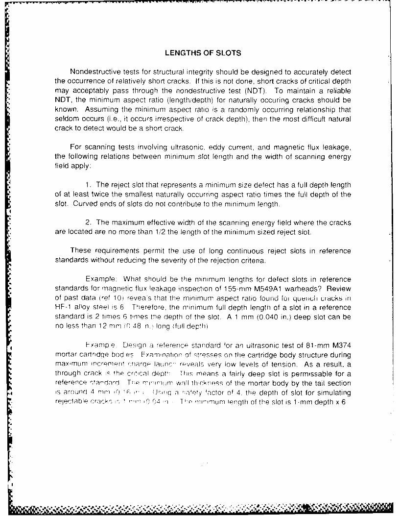
LENGTHS OF SLOTS
Nondestructive tests for structural integrity should be designed to accurately detectthe occurrence of relatively short cracks. If this is not done, short cracks of critical depthmay acceptably pass through the nondestructive test (NDT). To maintain a reliableNDT, the minimum aspect ratio (length/depth) for naturally occuring cracks should beknown. Assuming the minimum aspect ratio is a randomly occurring relationship thatseldom occurs (i.e., it occurs irrespective of crack depth), then the most difficult naturalcrack to detect would be a short crack.
For scanning tests involving ultrasonic, eddy current, and magnetic flux leakage,the following relations between minimum slot length and the width of scanning energyfield apply;
1. The reject slot that represents a minimum size defect has a full depth lengthof at least twice the smallest naturally occurring aspect ratio times the full depth of the
*slot. Curved ends of slots do not contribute to the minimum length.
2. The maximum effective width of the scanning energy field where the cracks*" are located are no more than 1/2 the length of the minimum sized reject slot.
These requirements permit the use of long continuous reject slots in referencestandards without reducing the severity of the rejection criteria.
Example: What should be the minimum lengths for defect slots in referencestandards for magnetic flux leakage inspection of 1 55-mm M549A1 warheads? Reviewof past data (ref 10) reveals that the minimum aspect ratio found for qu r uii uracks if]HF-1 alloy steel is 6 Therefore, the minimum full depth lengtn of a slot in a referencestandard is 2 times 6 times the depth of the slot. A 1 mm (0.040 in.) deep slot can beno less than 12 mm fl 48 in. long (full depth)
Example Design a referencr standard for an ultrasonic test of 81-mm M374mortar cartridge bodies Examination of stresses on the cartridge body structure duringmaximum increment r.harqP launch reveals very low levels of tension. As a result, athrough crack i the critical depth This means a fairly deep slot is permissable for areference ctandard Th- minimum wall thickness of the mortar body by the tail sectioni. is around 4 mm !r) 1C, ' Jci-q a -.afpty factor of 4, the depth of slot for simulatingrelectable crack ,,, -', 0 04 1, 1 Ili - minmuLm lenqth of the slot is 1-mm depth x 6

aspect ratio x 2 = 12 mm (0.48 in.) Maximum beam width of the transducer is 6 mm(0.24 in.). Beam width data from flat lensed ultrasonic transducers pulsing off a 9.5 mm(0.38 in.) precison steel ball immersed in water are listed in table 3. All of the minus 6db beam widths are less than the criterion of 1/2 x 12 mm = 6 mm (0.24 in.). Therefore,any of the evaluated transducers can be used for this nondestructive test application.
A similar analysis would apply to eddy current testing.
Table 3. Beam widths of six various sized ultrasonic transducerswith flat lenses immersed in water
Diameter of 5 Mhz Distance from a 3/8-in. Width of beam atactive elements steel ball for peak echo minus 6 db
mm in. mm in. mm in.
6.35 1/4 28.4 1.12 1.5 0.06
6.35 1/4 31.8 1.25 1.5 0.06
9.53 3/8 60.5 2.38 3.3 0.13
9.53 3/8 60.5 2.38 2.3 0.09
12.7 1/2 103 4.06 3.3 0.13
12.7 1/2 132 5.18 4.8 0.19
CONCLUSIONS
The design of reference standards for nondestructive tests (NDT) is a technology initself. Most of the work that has been done was just enough to satisfy productionrequirements. Much development work remains in the design of better NDT referencestandards.
There are many commonalities that permit slots, round holes, and plugs to simulatecracks in different types of nondestructive tests. For many, slots are the best way tosimulate cracks. Simulated cracks in NOT reference standards will continue to bepopular until industry learns how to control the size and orientation of made-to-orderquench cracks.
23

CIRCULAR ELECTRIC CURRENTMAGNETIC CONDUCTOR ROD
FIELD
jPLUG
REFERENCESTANDARD
REVELATION BYMAGNETIC
PARTICLES
Figure 1. Plug inserted in a tubluar shaped steel part makinga reference standard for a magnetic particle test
25

CIRCULAR ELECTRIC CURRENTMAGNETIC CONDUCTOR ROD
FIELD
REFERENCESTANDARD
REVELATION BYMAGNETICPARTICLES
Figure 2. Revelation by a reference standard that a magneticparticle test is out of control
26
O i

ULTRASONICTRANSDUCER
ACIV
____ ____ ____ __ _ ___METAL
Figure 3. Reflective area from the side of a hole
27

a
i THRESHOLD
, NATURAL
~~SIMULATEDCRC CRACK
AIR
IMPROPER ANGLE
THRESHOLD
SIMULATEDCRACK I NATURAL
CRACK
PROPER ANGLE
Figure 4. Proper angle of display for a horizontal alarm thresholdto minimize rejection error
28
I4

REFERENCES
1. MIL-STD-1949, Inspection, Magnetic Particle, U.S. Army, 1 August 1985.
2. MIL-STD-453C, Inspection, Radiographic. U.S Navy, 27 December 1984.
3. Liebowitz, H. (Editor), Fracture, An Advanced Treatise, Volume 5, Academic Press,NY & London, 1969.
4. Kies, J.A., Fracture Mechanics, Its Uses arid Limitations, U.S. Naval Research Lab,Washington, DC, 1965.
5. Krauthkramer, Josef and Herbert. Ultrasonic Testing of Materials, Second Edition,Springer-Verlag, Berlin, New York, 1977
6. Kloth, E., Untersuchug uber die AusbrietLung kurzer Schallimpulse bei derMaterialprufung mit Ultraschall. Forschungsber. Wirtsch.-u. Verkehrmin. Nordrhein-Westfalen No. 216, Cologne: Westdeutscher Verlag 1956.
7. ANSI/ASTM E 127-75, Standard Recommended Practice for Fabricating and-, Checking Aluminum Alloy Ultrasonic Standard Reference Blocks, 1975.
8. ASTM E 428-71, Standard Recommended Practice for Fabricating and Control ofSteel Reference Blocks Used in Ultrasonic Inspection, Reapproved 1980.
9. Eddy Current Depth of Penetration and Separation Angle Calculator, Nortec Corp.,1980.
10. Scott, Robert, Defect Correlation Analysis for Fixed Channel Ultrasonic InspectionSystem for Warhead, 155-mm, M549A1, U.S Army ARDC Technical Report QAR-Q-013, April 1979, p 9, Base 24.
"pr

GLOSSARY
The following are the definitions of some of the words and phrases used in thisreport. The definitions are specific to the application intended
Accumulation leakage test--a method of air leakage detection whereby air leakage isinduced and collected inside a sealed chamber. The rate of change in monitoredvacuum within the chamber reveals the rate of air leakage.
Copper crush gauge--a peak pressure measuring device consisting of a small cham-ber connected by an orifice to a pressure source. A small soft copper ball is placedbetween a hard piston and an anvil. Pressure forces the piston against the ball. Thediameter of the flat on the copper ball is directly related to the peak pressure that wasgenerated.
Crack--a narrow break. a fissure.
Defect--a discontinuity or group of discontinuties which produce indications that do notmeet a specified acceptance criteria.
Discontinuity-- an interruption in material which may or may not have undesirableconnotations.
Eddy current testing--a nondestructive test (NDT) whereby a monitored oscillatingmagnetic field is directed into electrically conductive material within which oscillatingelectric currents moving in circular paths are generated. The magnitude of magneticfield feedback can be used to sort metals, measure differences in electrical conductivityand magnetic permeability, and detect the presence of flaws.
Electrical conductivity--the ease with which free electrons flow within material, acrossjunctions, or through circuits.
Fatigue crack--a narrow break induced by repeated tensile and/or shear stress.
HF-i steel--a high strength, high carbon content steel containing no war reserve alloys.This steel was developed by Bethlehem Steel Corporation for the US. Government free
of charge.
Ketos--an oil hardening tool steel made by Crucible Steel Company
I

in
Liquid penetrant testing--an NDT where tight surface defects in materials can berevealed by applying a dye-containing, high-capillary-action liquid which enters tightdefects and amplifies their shapes by the bright color of its dye.
Magnetic flux leakage test--an NDT where discontinuties on surfaces or within thewalls of ferromagnetic material are detected by applying a direct current saturatingmagnetic field and scanning one wall surface for deflections in the applied magneticfield.
Magnetic particle test--an NDT where flaws on surfaces or within walls of mag-netizable material are outlined by the congregation of minute, mobile, magnetic par-ticles. The particles are coated with either pigment or dye for high visibility. The par-ticles are attracted to deflections in a magnetic field that are caused by the presence of
:discontinuities.
Magnetic premeability.-the ease with which a magnetic field or flux can be set up in amagnetic circuit. A value of one (for air, vacuum, and water) designates great difficulty.Much higher values (in the thousands for iron) designate ease.
Martensite--A common constituent of rapidly cooled steel. It is a highly stressed struc-
ture supersaturated with carbon and is strong, hard, and brittle.
Nondestructive--no injury to, no alteration of.
Polar gate--a circular threshold surrounding the source of a signal on a cathode ray
tube screen where any signal exceeding the circular threshold triggers an alarm
Munitions--the expendable, damage-inflicting portion of weapon systems (e.g.,cartridges. projectiles, bombs, grenades, mines, etc. are all munitions for tank, howitzer,bomber, infantry man, helicopter, etc
*; Proof testing--a test of strength where the strength of an item is physically tried close itits breaking point
Quench crack--a narrow break caused by localized tensile and/or shear stresses whichexceed the strength of the material. Quench cracks usually occur during heat treatment
,O when a red hot part is rapidly cooled
Radiography test--an NDT where exeedingly short wave-lengths of energy (x-rays,gamma rays) or atomic particles (neutrons, protons, and electrons) are used topenetrate opaque materials and record images on film (a radiograph) or on aphotosensor
'1

Reference standard (measurement standard)--a measuring system or artifact thatfixes a correlation with defects of interest in a particular part so that NDT equipment canestablish and maintain accuracy.
Reject--unwanted, refused.
Scanning--to examine the surface or full depth of a part by continuous coverage over* adjacent small portions.
Sensitivity--a measure of the ability of an ultrasonic system to detect small discon-tinuities. The same concept also applies to other types of NDT.
-: Ultrasonic flaw detection test--an NDT where high frequency sound pulses aredirected through a material. Encountered discontinuties will reflect back part of theultrasonic pulse. The presence of discontinuties can be detected by monitoring eitherreflected pulses or reduced pulse transmission through a material.
0
33

DISTRIBUTION LIST
CommanderArmament Research, Development
and Engineering CenterU.S. Army Armament, Munitions
and Chemical CommandATTN: SMCAR-IMI-I(D) (5)
SMCAR-AEE(D)SMCAR-AEF(D)SMCAR-AET(D)SMCAR-ASM(D)SMCAR-CCH(D)SMCAR-CCL(D)SMCAR-FSA(D)SMCAR-FSM(D)SMCAR-FSN(D)SMCAR-FSP(D)SMCAR-FSS(D)
Picatinny Arsenal, NJ 07806-5000
CommanderU.S. Army Armament, Munitionsand Chemical Command
ATTN: AMSMC-GCL(D)AMSMC-QAA(D)AMSMC-QAF(D)AMSMC-QAH(D)AMSMC-QAN(D)AMSMC-QAR(D)AMSMC-QAT(D) (10)AMSMC-QAU(D)
Picatinny Arsenal, NJ 07806-5000
AdministratorDefense Technical Information Center
,O ATTN: Accessions Division (12)Cameron StationAlexandria, VA 22304-6145
35
,-. - .
CommanderU.S. Army Armament, Munitions
and Chemical CommandATTN: SMCAR-ESP-L(R)
SMCAR-ESM(R)SMCAR-EST(R)SMCAR-ESW(R)
Rock Island, IL 61299-6000
DirectorU.S. Army TRADOC SystemsAnalysis Activity
ATTN: ATTA-SLWhite Sands Missile Range, NM 88002
CommanderU.S. Army Armament, Munitions
and Chemical CommandATTN: AMSMC-QAC(A)
AMSMC-QAE(A)AMSMC-QAO(A)
Aberdeen Proving Ground, MD 21010-5423
CommanderU.S. Army Armament, Munitions and
Chemical CommandATTN: AMSMC-QAD(R)
AMSMC-QAG(R)AMSMC-QAI(R)AMSMC-QAK(R)AMSMC-QAL(R)AMSMC-QAM(R)
*i AMSMC-QAS(R)AMSMC-QAV(R)AMSMC-QAW(R)
Rock Island, II 61299-6000
CommanderLone Star Ammunition PlantATTN- SMCLS-QATexarkana, TX 75505-9101
36
l;i I..
"! CommanderLonghorn Army Ammunition PlantATTN: SMCLO-QAMarshall, TX 75670
CommanderLouisiana Army Ammunition PlantATTN: SMCLA-QAShreveport, LA 71130
CommanderMcAlester Army Ammunition PlantATTN: SMCMC-QAMcAlester, OK 74501
CommanderMilan Army Ammunition PlantATTN: SMCMI-QAMilan, TN 38358
CommanderU.S. Army Pine Bluff ArsenalATTN: SMCPB-QAPine Bluff, AR 71602-9500
,
CommanderRed River Army Ammunition PlantATTN: SARRR-QATexarkana, TX 75501
CommanderU.S. Army Research and Technology LaboratoriesATTN; DAVDL-EUFt. Eustis, VA 23604
Director* U.S. Army Research and Technology Laboratories
AMES Research CenterATTN: DAVDL-ASMoffett Field, CA 94035
37

DirectorU.S. Army Materiel Systems
Analysis ActivityATTN: AMXSY-MPAberdeen Proving Ground, MD 21005-5066
CommanderChemical Research, Developmentand Engineering Center
U.S. Army Armament, Munitionsand Chemical Command
ATTN: SMCCR-MSIAberdeen Proving Ground. MD 21010-5423
CommanderChemical Research, Development
* and Engineering CenterU.S. Army Armament, Munitionsand Chemical Command
ATTN: SMCCR-RSP-A*Aberdeen Proving Ground, MD 2101-5423
DirectorBallistic Research LaboratoryATTN: AMXBR-OD-STAberdeen Proving Ground, MD 21005-5066
ChiefBenet Weapons Laboratory, CCACArmament Research, Development
and Engineering CenterU.S. Army Armament, Munitionsand Chemical Command
ATTN: SMCAR-CCB-TLWatervliet, NY 12189-5000
.I
38

*L U
-P i A