Embed Size (px)
Citation preview
Abstract—Thesubject of this paper is a modeling method of
switched reluctance generator (SRG) based on the nonlinear inductance model and electromagnetic field finite element analysis (FEA) to be used in wind energy applications. SRG and its behavior, modeling and Simulations results are presented. It was analyzed the characteristics of the SRG under different conditions. The nonlinear inductance model allows us to develop a control strategy that gives high performance controller with a closed loop was designed on PI controller.
Index Terms—Switched reluctance generator, finite element analysis, proportional integrator + current chopping control, wind applications.
I. INTRODUCTION The rapid depletion of fossil fuels has necessitated the
need for the utilization of non-conventional energy sources. Among these renewable energies widely used around the world in the last years, wind energy conversion system seems to be very interesting, it is clean energy source suitable for rural areas and the stand alone wind energy conversion system in rural areas must be characterized by economic and maintenance free operation.
Doubly fed induction generator (DFIG) suffers from limited rotor converter rating and has problems with over currents during voltage dips and the multistage gearbox that the DFIG must incorporate is unreliable and expensive. The direct coupled variable speed generators for these systems obviate the need for gear box which is the most unreliable and maintenance intensive component in the system. Permanent Magnet Synchronous Generator or Field Wound Synchronous Generator in standalone wind energy conversion systems eliminate the unreliability associated with gear box drive trains through direct coupled variable speed operation and even though permanent magnet machines will have a better torque density than the field wound version, the presence of permanent magnets will make assembly more difficult [1]. In the Field Wound Synchronous Generator, the brushes required to excite the field winding demand maintenance at regular intervals. The variable speed direct drive synchronous generator shortfalls
from cost, size, weight, energy yield and requirement of a converter.
Although Permanent magnet generators exhibit low losses, lower weight, better torque density and perhaps low cost with the disadvantage that the excitation cannot be controlled while axial flux permanent magnet generators are heavier and more expensive than radial flux counterparts.
To overcome the beyond mentioned obstacles Switched Reluctance Generator (SRG) is being considered as the generator of choice in standalone wind energy conversion systems.
The SRG is a doubly salient machine. It does not contain any magnets or brushes, and the phases are completely independent. The rotor is made of laminated iron and it does not have any winding. This makes the SRG also mechanically suitable for high speed applications [2].
Unfortunately, SRG is a multivariable, strong-coupling and nonlinear system, it is very difficult to model and analyze. To do so, lots of modeling methods were studied in literature. The circuit simulation program “SPICE”, it has certain limitations [3]. Reference [4] uses object oriented program technique, it is very flexible, but it is difficult to actualize, because it needs the complete mathematical model of the system. Reference [5] introduces some modules and M-file in MATLAB to build the nonlinear mathematical model of the magnetization curves, it is accurate, but the simulation speed is slow.
In this study we propose a nonlinear modeling method based on circuit simulation built by self-defining M-functions and basic modules on Simulink library. This model is very flexible and visual, its simulation speed is very fast [6].
The control of the (SRM) is more complicated for generator operation than it is for motor. In generator mode, the turn-on and turn-off angles control the peak phase currently jointly and severally.
II. OPERATING PRINCIPLE OF SRG The structure of SRG is double protruding pole. The SRG
in Fig. 1 has steel laminations on the rotor and stator. There are no windings or permanent magnets on the rotor, and there are concentrated windings placed around each salient pole on the stator. The coils around the individual poles are connected to form the phase windings.
The SRG has two phases (excitation and generation) in one electrifying period, with generation being the primary phase. When the two switches, S1 and S2, are turned on, the windings on the stator are excited by the outer circuit, and
Nonlinear Modeling and Simulation of a Four-phase Switched Reluctance Generator for Wind Energy
Applications
127DOI: 10.7763/JOCET.2013.V1.30
Manuscript received November 23, 2012; revised January16, 2013.F. Messai, M. Makhlouf, and K. Nabti are with Department of Electrical
Engineering, Faculty of Engineering Sciences Mentouri University Route d’Ain El Bey, Constantine, Algeria (e-mail: [email protected]).
A. Messai is with Laboratory of electromagnetism and telecommunications(L.E.T) Mentouri University Route d’Ain El Bey, Constantine, Algeria (e-mail: [email protected]).
F. Messai, M. Makhlouf, A. Messai, K. Nabti, and H. Benalla
Journal of Clean Energy Technologies, Vol. 1, No. 2, April 2013
the electrical energy and mechanical energy provided by exterior circuit are converted into magnetic field energy.
When the two switches are turned off and the two diodes, D1 and D2, are turned on, the magnetic field energy and mechanical energy are converted into electricity energy feeding back to the source or supplying power to the load. Because of the characteristics of time-sharing excitation, the control of SRG is very flexible. And there are several parameters for controlling SRG, such as turn-on angle, turn-off angle, and exciting voltage and controlling mode, all these will affect the generation greatly.
Fig. 1. Simplified diagram of the SRG’s structure.
A. Basic Equations of SRG The dynamic mathematical model of SRG includes two
basic nonlinear equations, such as electromagnetic equation and flux linkage equation which are respectively as:
dtkid
kiRkV),(
.θψ
+=±
(1)
where Vk is terminal voltage of the winding, ikis phase current k (k = a, b, c, d),Ris phase resistance, ),( kiθψ is phase flux linkage,θ is position angle of the rotor.
The sign before kV is determined by the operating mode of the system.
Because of the double salient structure of the machine and the magnetic saturation effect, the flux in the stator phases varies according to the rotor position θ and the current of each phase.
),( kiθψ = Lk ( ki,θ ). ki (2)
Lk ( ki,θ ) is phase inductance, it’s depending to the phase current and the rotor position.
B. Nonlinear Model of Inductance According to the nonlinearinductance model used in this
paper an SRG model is built based on the electromagnetic field finite-element analysis.
The magnetic circuit of the SRG is saturated and non-linear.
The harmonic component of the inductance can be expressed.
).cos().()(),( 10 πθθ ++= rkk NiLiLiL (3)
2)()(
)( minmax0
iLiLiL
+=
(4)
2)()(
)( minmax1
iLiLiL
−=
(5)
where Lmax is aligned position inductance, Lmin is the unaligned position inductance.
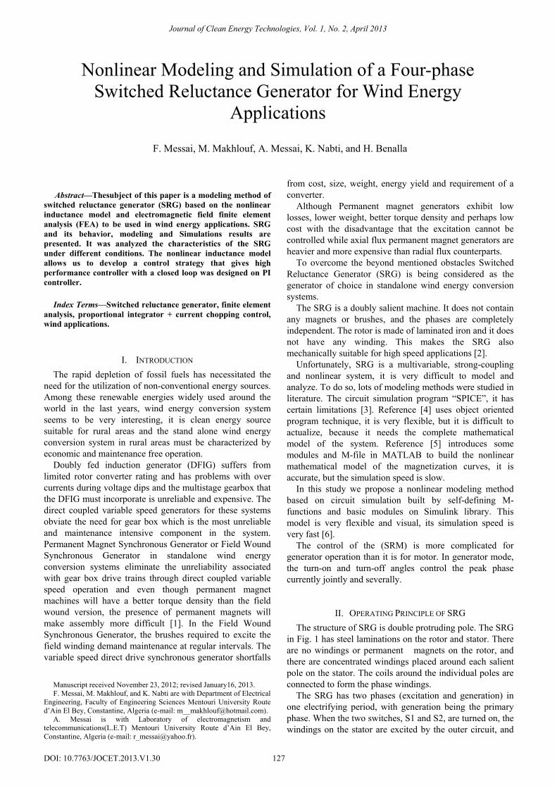
Fig. 2 shows the relationship between inductance, turn angle of rotor and phase current.
Fig. 2. Relationship between inductance, turn angle of rotor and phase
current.
Lmax, Lmin can be obtained by experiments and electromagnetic field finite element analyzes (FEA). Lmax(i) can be expressed as a polynomial function with respect to the phase current which can be obtained by curve fitting Fig. 3.
Fig. 3. Fitting curve of Lmax(i).
Lmax(i)= nin
na∑=
4
0
= 0.136-0.0045i+0.0056i2- 0.022i3+0.00035i4 (6)
C. Torque The variation of the magnetic energy from which a non-
null average torque will result has been made by the variation of the reluctance between two extreme positions of aligned and unaligned positions.
The torque can be expressed by:
2),(21 i
didLTe ⋅⋅=
θθ
(7)
The production of the torque does not depend on the sign
of current but only on the sign ofdLdθ
.
III. POWER CONVERTER The principle type converter used in the Switched
Reluctance Generator is the classical half-bridge converter which has two power switches and two diodes per phase. Fig. 4 shows the structure of a four-phase power inverter, the main advantage of this inverter is that each phase can be controlled independently.
128
Journal of Clean Energy Technologies, Vol. 1, No. 2, April 2013
Fig. 4. Power Inverter system of a four-phase SRG.
IV. NONLINEAR SIMULATION MODEL OF SRG Four assumptions are introduced In order to simplify the
simulation process, as follows: • Parameters of each phase in SRG are symmetrical. • Ignore mutual inductance and leak inductance. • Ignore hysteric’s and eddy effect. • Switches in power converter are ideal device and the
exciting source is constant.
A. Model of Each Phase We present the model of windings, it is built according to
(1)-(7). The parameters of each phase are symmetrical, take phase (a) example, its simulation model shows the detailed structure of the nonlinear machine modeling is created by Embedded Block in Fig. 5.
The three other phases are identical but different just on the level from the value of the angular shift where we take 0° for the phase (a), θs for the phase (b), 2θs for the phase (c), and 3θs for the phase (d), θs is defined as:
1/Ns) - r(1/N 2 = Πsθ (8)
Fig. 5. Inductance and current Calculator.
In this block, we can also calculate the inductance and the
torque of a one phase by applying the formulas (3) to (7), with Lmin = 0.01H.
B. Controllers of SRG The objective of the controller system is to create a high
performance control commands to maintain the output voltage of the system. The performance controller seriously affects the dynamic and static characteristics of the system. For SRG, there are lots of controllable parameters. Turn-off angle θoff, turn on angle θon, turn-off peak current Icand so on.
As a result, there are three typical control strategies. Angle position Control (APC), Current Chopping Controller (CCC) and Pulse Width Modulation (PWM).
Because the performance of system is very sensitive to the turn-off angle, the implement of APC has certain difficulties. In this paper, a high-performance control
strategies named PI+CCC control (PCC) is proposed. The controller has two closed loops: outer voltage closed-loop (VC) and inner current closed-loop (CC).
VC shown in Fig. 6 is based on PI controller. Firstly it obtains the D-value between the output voltage of the system and the given voltage signal (270V), and then creates the reference current Iref through PI controller.
CC is based on current chopping control; it is implemented by the Relay module in Simulink library as shown in Fig. 7. By the way, turn-on and turn-off angle in this controller is optimized and fixed.
Fig. 6. the simulation model of outer voltage controller.
Fig. 7. The simulation model of Phase (a).
C. Model of Prime Motor Prime motor is imitated by position sensor as shown in
Fig. 8. The speed of the rotor is integrated to obtain the mechanical angle of the rotor. Original angle supplies the original angle of the rotor as the system is started up.
Fig. 8. the simulation model of position sensor.
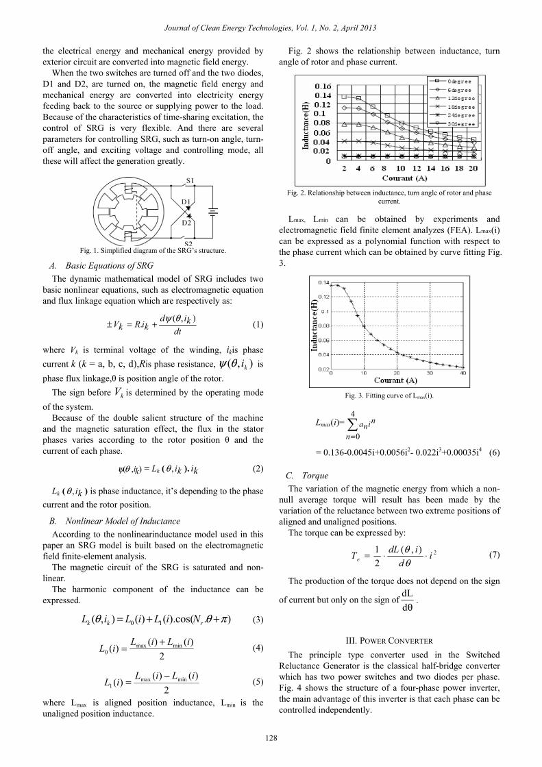
D. Exciting Circuit and Loads The direct current exciting source VDC supplies the
original exciting current to the windings. The Diode module over VDC is used to prevent the current of SRG from returning to VDC.
Fig. 9. PSB simulation model of exciting source and loads.
1
Iref
270
given voltage signal
1s
Ki
Kp
1
Vout
1
position -C-
original angle
-C-
Speed
1s
10
D2
9
D1
8
C2
7
C1
6
B2
5
B1
4
A2
3
A1
2
V-
1
V+
PulseGenerator1
G
V+
V-
U1
D1
D2
G1
Phase D
G
V+
V-
U1
C1
C2
G1
Phase C
G
V+
V-
U1
C1
C2
G1
Phase B
G
V+
V-
U1
C1
C2
G1
Phase A
gm
CE
IGBT1
emu1
G
Cont
Cont
Cont Cont
V1
Cont
129
Journal of Clean Energy Technologies, Vol. 1, No. 2, April 2013
The switching device over load it use to imitate sudden load-on and load-off, it is composed of an IGBT module and a step-function signal module.
The exciting circuit and the load are simulated using the model shown in Fig. 9.
To test the proposed model feasibility a four phase 8/6 SRG system is built and simulated as shown in Fig. 10.
The rated parameters of the SRG are 3000r.p.m, 250 volt. The SRG was simulated under different conditions.
Fig. 10. Simulation Model of SRG System.
V. NONLINEAR SIMULATION RESULTS Fig. 11 shows the nonlinear inductance phase and its
variation when the rotor position changed.
Fig. 11. Nonlinear inductance (H).
When speed is increased, the phase current is reduced and
the generating capacity of SRG is degraded.
Fig. 12. phase current Waveforms with different speeds.
The exciting process can be controlled by regulating the
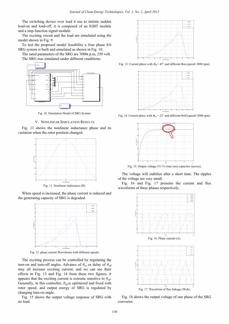
turn-on and turn-off angles. Advance of θon or delay of θoff may all increase exciting current; and we can see their effects in Fig. 13 and Fig. 14 from these two figures, it appears that the exciting current is extreme sensitive to θoff. Generally, in this controller, θoff is optimized and fixed with rotor speed, and output energy of SRG is regulated by changing turn-on angle.
Fig. 15 shows the output voltage response of SRG with no load.
Fig. 13. Current phase with θoff= 45° and different θon,(speed=3000 rpm).
Fig. 14. Current phase with θon = 22° and different θoff,(speed=3000 rpm).
Fig. 15. Output voltage (V) Vs time (ms) capacitor (across).
The voltage will stabilize after a short time. The ripples
of the voltage are very small. Fig. 16 and Fig. 17 presents the current and flux
waveforms of three phases respectively.
Fig. 16. Phase current (A).
Fig. 17. Waveform of flux linkage (Web).
Fig. 18 shows the output voltage of one phase of the SRG
converter.
U0Iref
controller
Position
Iref
Pulse A
Te
Pulse B
Ic
Pulse C
FLUX
Pulse D
A+
B+
C+
D+
A-
B-
C-
D-
SRGDS 8/6
G
U0
A1
A2
B1
B2
C1
C2
D1
D2
CONVERTER
position
position sensor
0 10 20 30 40 50 600
0.02
0.04
0.06
0.08
0.1
0.12
0.14
Rotor Position(Degree)
Indu
ctan
ce(H
)
20 30 40 50 60 70 800
2
4
6
8
10
12
14
16
18
20
Rotor Position(Degree)
Cur
rent
(Am
ps)
3500rpm
3000rpm
2500rpm
20 25 30 35 40 45 50 55 60 65 700
2
4
6
8
10
12
14
16
18
20
Rotor position(Degree)
Cur
rent
(Am
ps)
20 Degree
22 Degree
24 Degree
20 25 30 35 40 45 50 55 60 65 700
2
4
6
8
10
12
14
16
18
20
Rotor Position(Degree)
45 Degree
43 Degree
40 Degree
0 0.5 1 1.5 2 2.5 3
x 10-5
0
50
100
150
200
250
300
Time(s)
Out
put V
olta
ge(V
)
3 4 5 6 7 8 9 10
x 10-3
0
0.5
1
1.5
2
2.5
3
3.5
4
4.5
5
Time(s)
Cur
rent
(Am
ps)
IA(Amps)
IB(Amps)
IC(Amps)
ID(Amps)
3 4 5 6 7 8 9 10
x 10-3
0
0.05
0.1
0.15
0.2
0.25
0.3
0.35
0.4
Time(s)
Flux
link
age(
Web
)
PsiA
PsiB
PsiC
PsiD
130
Journal of Clean Energy Technologies, Vol. 1, No. 2, April 2013
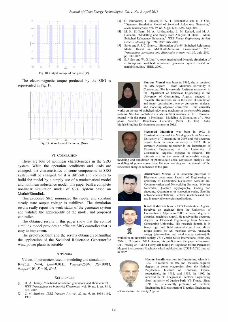
Fig. 18. Output voltage of one phase (V).
The electromagnetic torque produced by the SRG is
represented in Fig. 19.
Fig. 19. Waveform of the torque (Nm).
VI. CONCLUSION There are lots of nonlinear characteristics in the SRG
system. When the operation conditions and loads are changed, the characteristics of some components in SRG system will be changed. So it is difficult and complex to build the model by a simply use of a mathematical model and nonlinear inductance model, this paper built a complete nonlinear simulation model of SRG system based on Matlab/Simulink.
This proposed SRG minimized the ripple, and constant steady state output voltage is stabilized. The simulation results really report the work status of the generator system and validate the applicability of the model and proposed controller.
The obtained results in this paper show that the control simulink model provides an efficient SRG controller that is easy to implement.
The prototype built and the results obtained confirmthat the application of the Switched Reluctance Generatorfor wind power plants is suitable
APPENDIX Values of parameters used in modeling and simulation.
R=25Ω, Nr=4, Lmin=0.01H, Vexciting=250V, RL=100Ω, θoriginal=10°, Kp=10, Ki=5.
REFERENCES [1] D. A. Torrey, “Switched reluctance generators and their control,”,
IEEE Transactions on Industrial Electronics , vol. 49, no. 1, pp. 3-14, Feb. 2002
[2] C. M. Stephens, IEEE Trans.on I A, vol. 27, no. 6, pp. 1098-1102, 1991.
[3] O. Inhinokura, T. kikuchi, K. N. T. Uatannable, and H. J. Guo, “Dynamic Simulation Model of Switched Reluctance Generator,” IEEE Transactions, vol. 39, no. 5, pp. 3253-3255, Sep. 2003.
[4] M. K. EI-Nemr, M. A. Al-khazendar, E. M. Rashad, and M. A. Hassanin, “Modelling and steady state Analysis of Stand – Alone Switched Reluctance Generator,” IEEE Power Engineering Society General Meeting, pp. 1894-1899, July 2003
[5] Sores and P. J. C. Branco, “Simulation of a 6/4 Switched Reluctance Model Based on MATLAB/Simulink Enviorment,” IEEE Transactions Aerospace and Electronics system, vol. 37, July 2005, pp. 989-1009.
[6] S. J. Son and W. G. Liu, “A novel method and dynamic simulation of a four-phase switched reluctance generator system based on matlab/simulink,” IEEE, 2007.
Feyrouz Messai was born in 1982, she is received the MS degrees from Mentouri University of Constantine. She is currently Assistant researcher in the Department of Electrical Engineering at the University of Constantine, Algeria, engaged in research. His interests are in the areas of simulation and motor optimization, energy conversion analysis, and modeling ofpower converters. She currently
works on the use of switched reluctance machines in the renewable energy systems. She has published a study on SRG machine in EEE Canadian journal with the paper « Nonlinear Modeling & Simulation of a Four phase Switched Reluctance Generator (SRG DS 8/6) Under Matlab/Simulink Environment system» in 2012.
Messaoud Makhlouf was born in 1972 in Constantine received the MS degrees from Mentouri University of Constantine in 2006 and hid doctorate degree from the same university in 2012. He is currently Assistant researcher in the Department of Electrical Engineering at the University of Constantine, Algeria, engaged in research. His interests are in the areas of renewable energy,
modeling and simulation of photovoltaic cells, conversion analysis, and modeling of power convert²ers. He now working on the domain of the renewable energies connected to the grid.
Abderraouf Messai is an associate professor in Electronic department Faculty of Engineering at university of Constantine his interest domains are: Communication and Networking Systems, Wireless Networks, Quantum cryptography, Coding and decoding, Quantum error correction codes, Satellite networks constellations, Electrical machines and their use in renewable energies applications. Khalil Nabti was born in 1979 Constantine, Algeria. Received an engineer from the University of Constantine / Algeria in 2003; a master degree in electrical machines control. He received the doctorate degrees in Electrical Engineering from Mentouri Constantine University. His research domain is in fuzzy logic and field oriented control and direct torque control for AC machines drives, renewable energy (photovoltaic and wind energy systems).He
worked in an industrial society VSI (Verrier Silice international) from July 2004 to November 2005. Among his publications the paper « Improved DTC relying on Hybrid Fuzzy-self tuning PI Regulator for the Permanent Magnet Synchronous Machine» which published in ICGST-ACSE Journal in 2009.
Hocine Benalla was born in Constantine, Algeria in 1957. He received the MS, and Doctorate engineer degrees in power electronics, from the National Polytechnic Institute of Toulouse, France, respectively, in 1981, and 1984. In 1995, he received the PHD degrees in Electrical Engineering from university of Jussieu-Paris VI; France. Since 1996, he is currently professor of Electrical Engineering in Department of Electrical Engineering
at Constantine University Algeria.
0.12 0.125 0.13 0.135 0.14 0.145 0.15 0.155 0.16-300
-200
-100
0
100
200
300
Times(s)
Vol
tage
(V)
0.046 0.047 0.048 0.049 0.05 0.051 0.052 0.053 0.054-9
-8
-7
-6
-5
-4
-3
-2
-1
0
Time(s)
Torq
ue(N
m)
131
Journal of Clean Energy Technologies, Vol. 1, No. 2, April 2013


![Linear and Nonlinear Model of Hydro Generator System with ... · [2] Chen Naixiang. Hydraulic transient simulation and control of hydraulic and hydroelectric engineering[M]. China](https://img.pdfslide.net/doc/110x75/5f33d1251a35ef23ec175d14/linear-and-nonlinear-model-of-hydro-generator-system-with-2-chen-naixiang.jpg)