Embed Size (px)
Citation preview
"AD-A262 793
R L-TR-92-278Final Technical Report ELECDecember 1992 APR1 41993
NONLINEAR OPTICS IN THREELEVEL ATOMIC SYSTEMS
Massachusetts Institute of Technology
Professor S. Ezekiel
APPROVED FOR PUBLA2 RELEASE, DISTRIBMTION UNLIMITED
"93-07670
l00 8tE II IIill 1111111
Rome LaboratoryAir Force Materiel Command
Griffiss Air Force Base, New York
This report has been reviewed by the Rome Laboratory Public Affairs Office(PA) and is releasable to the National Technical Information Service (NTIS). AtNTIS it will be releasable to the general public, including foreign nations.
RL-TR-92-278 has been reviewed and is approved for publication.
APPROVED: -f . ..
PHILIP R. HEMMERProject Engineer
FOR THE COMMANDER: vt l •;_
HAROLD ROTH, DirectorSolid State SciencesElectromagnetics and Reliability Directorate
If your address has changed or if you wish to be removed from the Rome Laboratorymailing list, or if the addressee is no longer employed by your organization,please notify RL ( EROP ) Hanscom AFB MA 01731. This will assist us in maintaininga current mailing list.
Do not return copies of this report unless contractual obligations or notices on aspecific document require that it be returned.

REPORT DOCUMENTATION PAGE . o.0704-0188_7902 Aopproe
Publ r~oIngtkug b • • ft d~~~o inUT,~ •. e0nud toww's I hourTB • flAr Q n f~r.t mm t0 I• r=t•U, 1w1 wmi-,r• da~n tGJ•:•r
gWtwV Mi k m t**v ISO d -~ Wid mnWr wd ruv~wkig Owuh~ d Hamthn~ S"x wffiwwuu*q tv~c V*I toon e U"orw UW- .T4JOa C9coko il a hiafg" tc efti tbu to Wo*i*Vi ttead.mm Swvbw OftUga to riammo Opwaftwed~m &spno.11 - efte, sc,OW* HVILW.' SLAM 1204, "VtM VA 2EM-43O ondto tur Ofila d FWOWuma-2 inxi Sdioý Pwwar Reaxckz Pmt'a (O0MM 4.0 W~w. OC 205M
1. AGENCY USE ONLY (Leave BIank 12. REPORT DATE 3. REPORT TYPE AND DATES COVERED
I December 1992 Final Jun 89 - May 92
4. TITLE AND SUBTITLE 5. FUNDING NUMBERSNONLINEAR OPTICS IN THREE LEVEL ATOMIC SYSTEMS C - F19628-89-K-0030
PE - 62702FAUT[HOR($) PR - 4600
TA - 19Prof. S. Ezekiel WU - 77
7. PERFORMING ORGANIZATION NAME(S) AND ADDRESS(ES) 8 PERFORMING ORGANIZATION
Massachusetts Institute of Technology REPORTNUMBER
Research Laboratory of Electronics N/ACambridge MA 02139
9. SPONSORING/MONITORING AGENCY NAME(S) AND ADDRESS'ES) 10. SPONSORING/MONITORING
Rome Laboratory (EROP) AGENCY REPORT NUMBER
Hanscom AFB MA 01731-5000 RL-TR-92-278
11. SUPPLEMENTARY NOTES
Rome Laboratory Project Engineer: Philip R. Hemmer/EROP/(617) 377-5170
i 2a. DISTRIBUTION/AVAILABILITY STATEMENT 12b. DISTRIBUTION CODE
Approved for public release; distribution unlimited.
13. ABSTRACT(muadn- 2w -ard•)
The nonlinear optical properties of three-level atomic systems in the resonanceRaman configuration are investigated both theoretically and experimentally. Specialemphasis is placed on the optical properties which are unique to three-level systems,and have potential device applications. In particular, microwave-phase-dependent
optical absorption is demonstrated experimentally. This is of interest because ofpotential applications to microwave circuit phase mapping, and mm-wave to FIR beamsteering and image conversion. Optical data storage with Raman excited microwavespin echoes is also demonstrated experimentally. This technique has potential forincreasing storage densities in optical echo memories and may lead to near-room-
temperature materials for echo storage and processing. Finally, the optical forceson three-level atoms in Raman resonant standing waves are studied to investigate thepotential for using trapped neutral atoms as nonlinear optical elements.
14. SUBJECT TERMS 11 NUMBER OF PAGES64
Nonlinear Optics, Resonance Raman, Atomic Beams IdPRIcECOoE
17. SECURITY CLASSIFICATION &SECURITY CLASSIFICATION 19. SECURITY CASSIFICATION 20. UMITATION OF ABSTRACTOF REPORT OF TH-IS PAGE OF ABSTRACT
UNCLASSIFIED UNCLASSIFIED UNCLASSIFIED ULNSN 754001-- 465 St. da• Farm 2W (Rf 2 ic
P,.bdl by ANSI S{td Z c'29WI02
The nonlinear optical properties of three-level atomic sys-
tems in the resonance Raman configuration are investigated both
theoretically and experimentally. Special emphasis is placed on
the optical properties which are unique to three level systems,
and have potential device applications. In particular,
microwave-phase-dependent optical absorption is demonstrated
experimentally. This is of interest because of potential appli-
cations to microwave circuit phase mapping, and mm-wave to FIR
beam steering and image conversion. Optical data storage with
Raman excited microwave spin echoes is also demonstrated exper-
imentally. This technique has potential for increasing storage
densities in optical echo memories and may lead to
near-room-temperature materials for echo storage and processing.
Finally, the optical forces on three level atoms in Raman reso-
nant standing waves are studied to investigate the potential for
using trapped neutral atoms as nonlinear optical elements.
Accesion For
NTIS CRA&IDIIC TAB 0
DTIC QUA•iT IN• 4 Unou.-ced 0Justif Iction
By_
Distribution t
Availability Codes
Avail andIorDist Special
1k A
FINAL REPORT
NONLINEAR OPTICS IN THREE LEVEL ATOMIC SYSTEMS
Summary of Objectives
The primary objective of this research program is to inves-
tigate the fundamental physical processes underlying nonlinear
optical interactions in three level atomic systems. This is
accomplished by performing detailed, systematic studies while
maintaining close agreement between experimental results and
theory. Special emphasis is placed on those optical properties
which are unique to three level systems, and which have potential
device applications. In particular, three level "Lambda" systems
in the resonance Raman configuration are studied because of the
existence of optically transparent, long-lived, coherent, quantum
superposition states in these systems.
Brief Review of Resonance Raman System and Transparent State
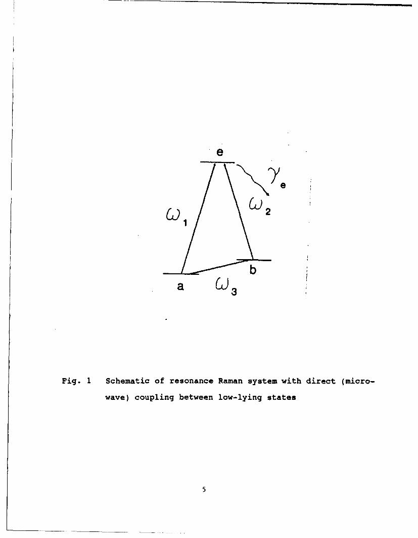
The laser excited resonance Raman interaction is illustrated
schematically in Fig. 1. Briefly, the low-lying states la> and
Jb> are coupled to a common excited state Je> by two laser fields
at frequencies w, and UU2, respectively. In addition, the two
low-lying states can also be coupled directly by a (microwave)
2
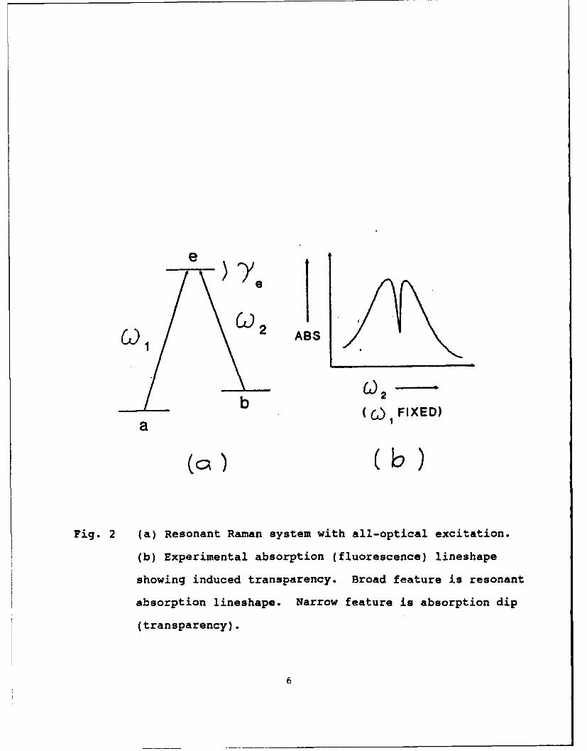
field at frequency ., as shown. In the case of all-optical
excitation it is always possible to find a coherent superposition
of the low-lying states which is decoupled from the excited sta-
te(l] (i.e. transparent to the resonant optical fields). When
the low-lying states are metastable, all the atoms become
optically pumped into the transparent state[2,3,4J. The result
is a decrease in the optical absorption or equivalently in the
fluorescence of the excited state, as shown in Fig. 2.
For nonlinear optical applications, the important feature of
the transparent Raman coherent state is its sensitivity to the
relative phase of the optical laser fields. This is important
because it is usually assumed that a two-level system is respon-
sible for nonlinear optical interactions in atoms. However, the
optical dipole moments induced in a two level system decay
rapidly (typically nanoseconds to milliseconds), so that large
photon flux (high laser intensity) is needed to observe nonlinear
phenomena. The Raman transparent state, in contrast, can survive
much longer than the excited state lifetime ,thereby enabling
nonlinear optical interactions to occur at much lower laser
intensities.
3
References -,brief review
11] H. R. Gray, R. M. Whitley, and C. R. Stroud, Jr., Opt. Lett.
3, 218 (1978).
[2] J. E. Thomas, P. R. Hemmer, S. Ezekiel, C. C. Leiby, Jr., R.
H. Picard, and C. R. Willis, Phys. Rev. Lett. 48, 867
(1981).
[3] G. Alzetta, A. Gozzini, L. Moi, and G. Orriols, Nuovo
Cimento 36B, 5 (1976).
[4] P. M. Radmore and P. L. Knight, J. Phys. B. 15, 3405 (1982)
e
a (3)3
Fig. 1 Schematic of resonance Raman system with direct (micro-
wave) coupling between low-lying states
5
e
CA. 1 2 ABS
b02(--) FIXED)a
Fig. 2 (a) Resonant Raman system with all-optical excitation.
(b) Experimental absorption (fluorescence) lineshape
showing induced transparency. Broad feature is resonant
absorption lineshape. Narrow feature is absorption dip
(transparency).
6
Research under this program concentrates on three major top-
ics: forces on three level atoms in Raman resonant standing wave
optical fields, microwave-phase-dependent optical absorption, and
optically excited microwave spin echoes. Each of these topics
are discussed separately in the remainder of this report.
(I) Forces on Three Level Atoms in Raman Resonant Standing Wave
Optical Fields
The ideal nonlinear optical material is an ensemble of non-
interacting atoms, driven near resonance. In existing materials,
interactions between atoms and the environment significantly
weaken the resonant nonlinear optical response. One way around
this problem is to devise a novel nonlinear optical medium which
consists of atoms stored in a neutral atom trap. Unfortunately,
existing atom traps are sufficiently shallow that the nonlinear
optical interaction can easily generate forces which are large
enough to eject atoms from the trap, thereby preventing cw opera-
tion. Thus, what is needed is a new type of trap, based on the
Raman transparent state, which permits cw nonlinear optical
interactions. To this end, the optical forces exerted on three
level atoms by Raman resonant fields is studied both theoreti-
cally and experimentally.
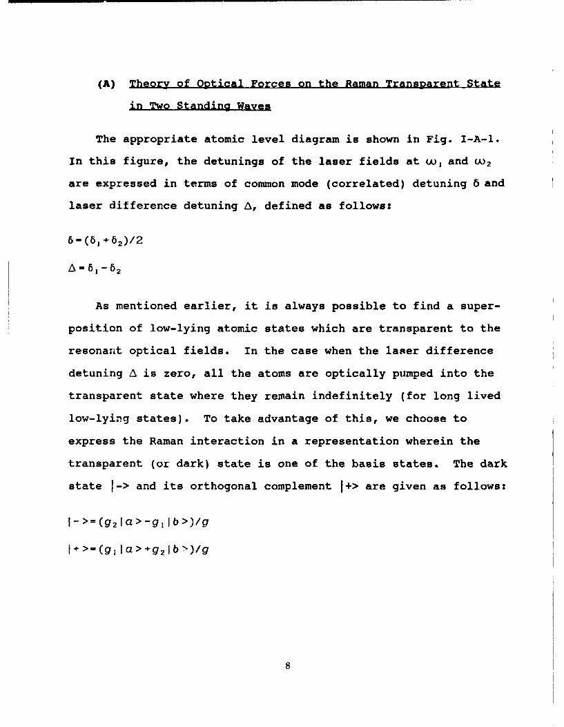
(A) Theory of Optical Forces on the Raman Transparent State
in Two Standing Waves
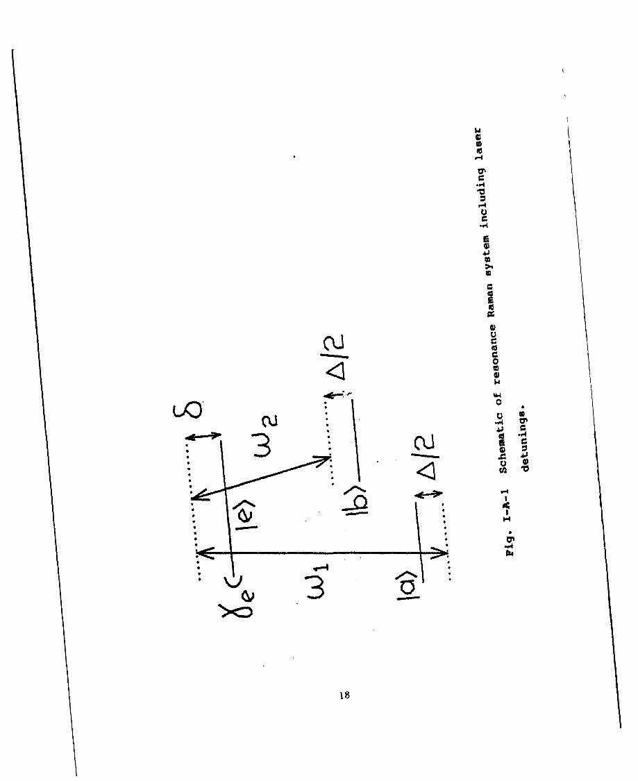
The appropriate atomic level diagram is shown in Fig. I-A-1.
In this figure, the detunings of the laser fields at w, and W 2
are expressed in terms of common mode (correlated) detuning 6 and
laser difference detuning A, defined as follows:
6-(61+ 62)/2
A - 61-62
As mentioned earlier, it is always possible to find a super-
position of low-lying atomic states which are transparent to the
resonant optical fields. In the case when the laser difference
detuning A is zero, all the atoms are optically pumped into the
transparent state where they remain indefinitely (for long lived
low-lying states). To take advantage of this, we choose to
express the Raman interaction in a representation wherein the
transparent (or dark) state is one of the basis states. The dark
state f-> and its orthogonal complement 1+> are given as follows:
1->=(g21a> -glb>)/g
I÷ >-(gIa> >+g, Ib7>)/g
where g, and g 2 are the Rabi frequencies corresponding to the
a <--> e and b <--> e transitions, respectively, and g- (g•÷g•).
For standing wave optical fields, the Rabi frequencies take the
following form:
g,=-g1 0 sin(kx)
g 2 = g 20sin(kx+X)
For simplicity, we consider only equal strength standing
waves, so that g90 -g 20 wg 0 . Also, the standing wave phase shift X
is assumed constant on the optical wavelength scale.
In one dimension, the Lorentz force is written as F=ir(pf).
Here, p is the density operator and f is the force operator given
by the product of the dipole operator and the gradient of the
electric field, 1=-ýiVE. For the system of Fig. I-A-l, the non-
zero elements of j are given, in the rotating wave approximation,
by the gradients of the Rabi frequencies:
,f.. -I.. 7g. 10.b fb.-qV2, (/ = 1).
To see how this dark state basis simplifies the interaction,
consider its Hamiltonian. To obtain this, we first write down
the Hamiltonian in the la>, lb>, and le> basis:
9
A 0 -gl]
H (1/2) 0 -A -92-g91 -92 -26_
where the zero of energy is chosen such that u,.26 -0. This
Hamiltonian can be obtained by inspection from Fig. I-A-i. Next,
we note that the I-> and I *> states can be expressed as a rota-
tion of the Ia> and Ib> states, where the rotation angle e is
defined by tanO-g 1 /g 2. Making the appropriate transformations
gives the Hamiltonian in the 1->, 1+> and fe> basis:
Acos(20) Asin(20) 0 1H (1/2) Asin(20) -Acos(20) -g
0 -g -26_
Now consider the force operator f in the dark state basis.
The nonzero elements are:
f,-_=f•=(g 2 Vgl-g 1 Vg 2)/g = gV
I,- =1%.= (g 1Vg91 g 2 Vg 2 )/g9 Vg
where I.- and I,. are real for pure standing wave excitation.
These elements can be derived by inspection by noting that the
force operator corresponding to the 1-> state, for example, is
10
simply a weighted sum of the Ia> and lb> state forc.e operators
where the weights are the same as in the definition of the 1->
state.
Using the results so far gives the following explicit form
for the force on a three level atom in standing wave fields:
F = f,_Re(p.,)+ I.. Re(p.,)
We now compute the optical force by estimating the steady-
state values of the density matrix elements in several limiting
cases. Consider the case when Asin(20) is non-zero but small
compared to the optical pumping rate, g 2/r. In this limit, the
nonzero density matrix elements can be obtained by perturbing
around the p__= I solution. To simplify the analysis further we
make the additional approximation that g«<<, and ignore the
influx of atoms into the 1+> and 1-> states from the je> state.
This allows us to avoid solving the complex density matrix equa-
tions (OBE's) entirely, by instead representing the system with a
wave function of the form VYA_[->+A.I+>+A.Ie>.
The dynamics of the system is now contained in the ->, 1+>,le> state amplitudes, whose equations of motion are given by the
Schrodinger equation:
II
A- AC As 0 A
TtA. -(-i/2) -As A -9 A.A4 -o -g -i(r-2i6)] [A.]
where AC- Acos(20), A,- Asin(20), and the phenomenological damping
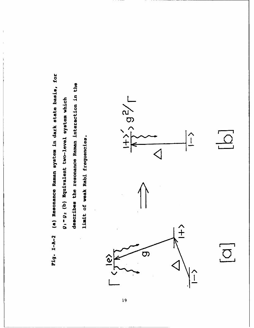
r is added to the Hamiltonian. The Raman interaction in this new
basis is illustrated in Fig. I-A-2(a)
Since F>>g, we can use the adiabatic following approxima-
tion[1,2,3], to solve for A.. The result is A,--i(g/Fr)A., where
F8 =[-2i0. Using this result to eliminate A., the wave function
now becomes, -=A_j->+A.I+>d. The new basis state
I+ >d=1+>-i(g/Eb)1e> is called the damped state. In the adia-
batic limit, the dark and damped states form a closed two level
system, as illustrated in Fig. I-A-2(b).
It is easy to show that the amplitude equations for the dark
and damped states are simply:
SA= (-i/2) [ c iF -AaA. As iF-~) A
where r.=g2/ir. Thus, the decay rate of the I÷>d state is the
optical pumping rate g 2/r6, which is proportional to total laser
intensity.
12
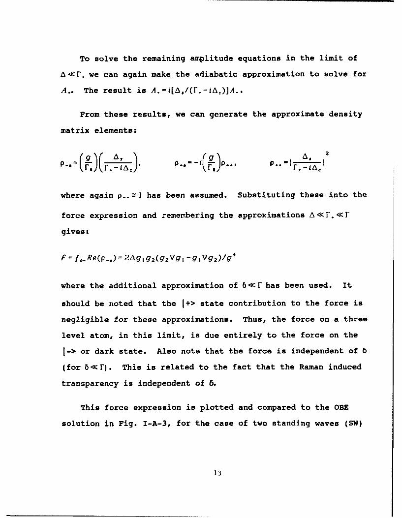
To solve the remaining amplitude equations in the limit of
6<<r. we can again make the adiabatic approximation to solve for
A.. The result is A.-i[6,1(r.-iA,)]A_.
From these results, we can generate the approximate density
matrix elements:
F.--t IT , .-I I
where again p. ] 1 has been assumed. Substituting these into the
force expression and remembering the approximations A << r.<< r
gives:
F -It..Re(p..)= 2Ag 1g 2(g 2 Vg9 -q1Vg 2 )/g 4
where the additional approximation of 6<<r has been used. It
should be noted that the 1+> state contribution to the force is
negligible for these approximations. Thus, the force on a three
level atom, in this limit, is due entirely to the force on the
1-> or dark state. Also note that the force is independent of 6
(for 6<<F). This is related to the fact that the Raman induced
transparency is independent of 6.
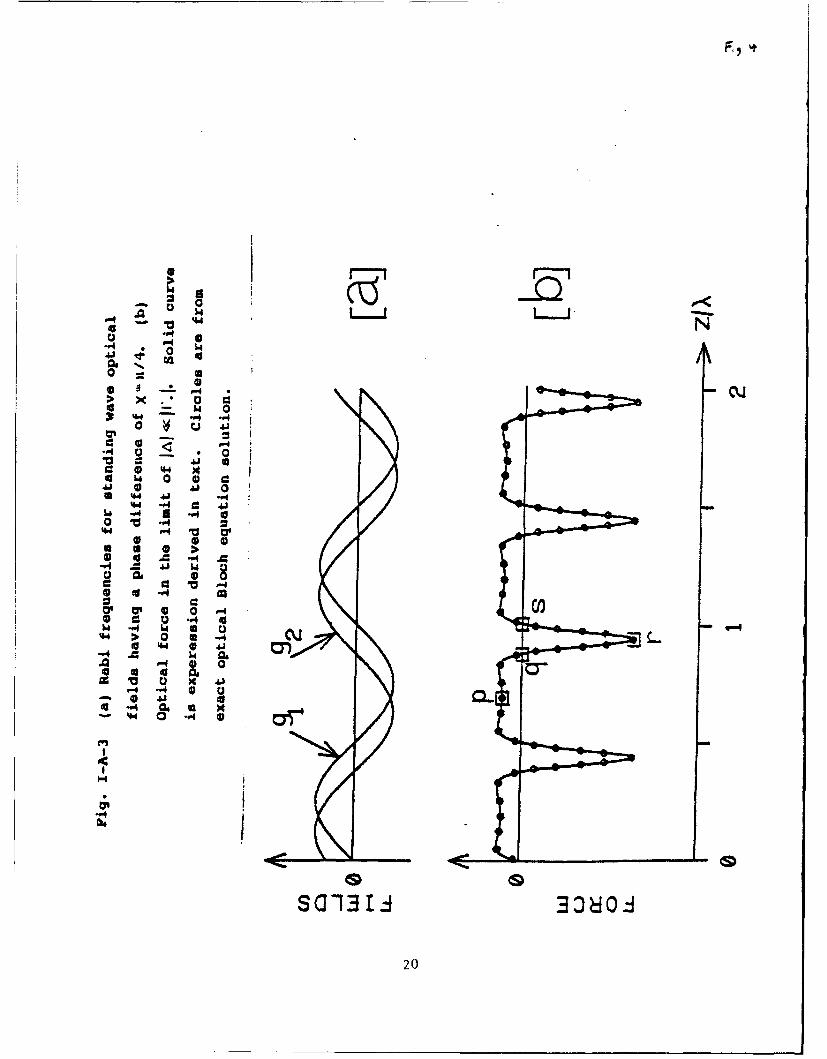
This force expression is plotted and compared to the OBE
solution in Fig. I-A-3, for the case of two standing waves (SW)
13
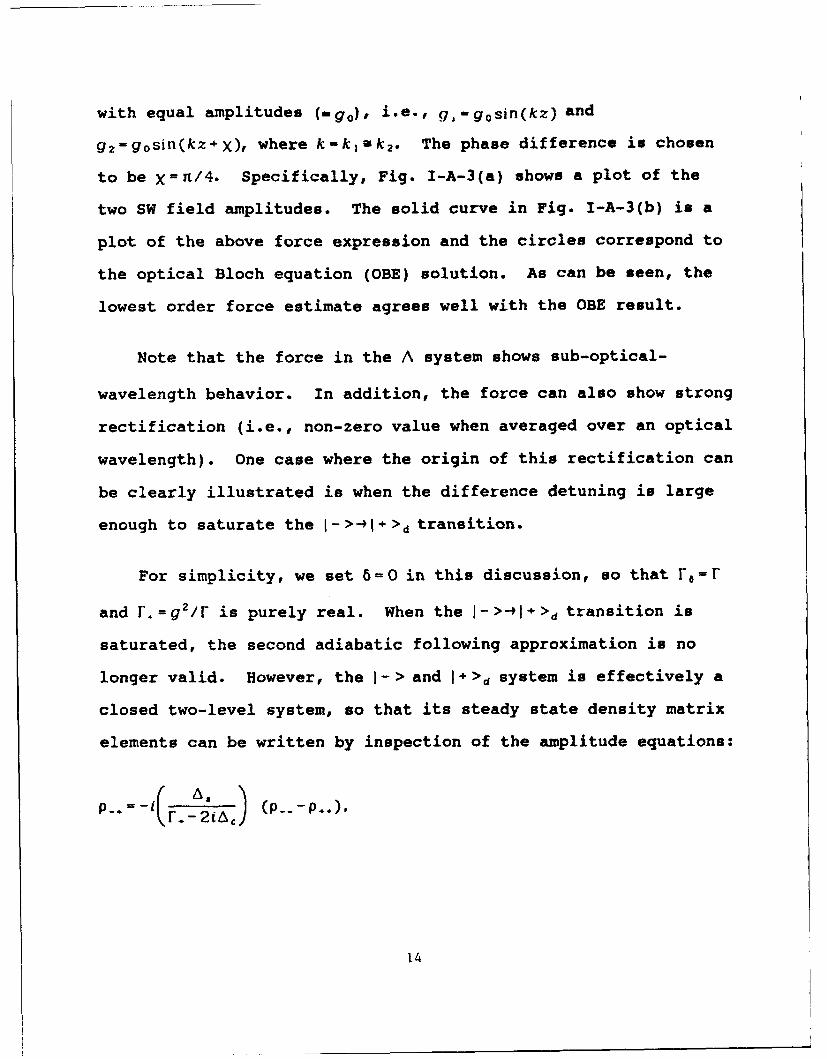
with equal amplitudes (mg 0 ), i.e., g,-g 0 sin(kz) and
g 2 -g 0 sin(kz+X), where k-kjak2. The phase difference is chosen
to be X= n/4. Specifically, Fig. I-A-3(a) shows a plot of the
two SW field amplitudes. The solid curve in Fig. I-A-3(b) is a
plot of the above force expression and the circles correspond to
the optical Bloch equation (OBE) solution. As can be seen, the
lowest order force estimate agrees well with the OBE result.
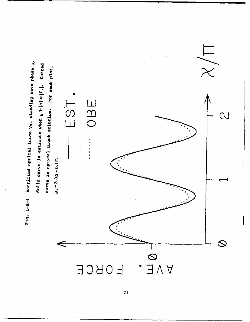
Note that the force in the A system shows sub-optical-
wavelength behavior. In addition, the force can also show strong
rectification (i.e., non-zero value when averaged over an optical
wavelength). One case where the origin of this rectification can
be clearly illustrated is when the difference detuning is large
enough to saturate the I-> -1+>d transition.
For simplicity, we set 6=0 in this discussion, so that r6=r
and [.=g 2/r is purely real. When the j->-ýfl+>d transition is
saturated, the second adiabatic following approximation is no
longer valid. However, the 1-> and I+>d system is effectively a
closed two-level system, so that its steady state density matrix
elements can be written by inspection of the amplitude equations:
p_.=- F. - ) (p_.-p..),
14
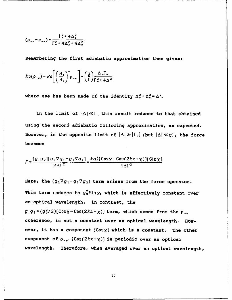
r 2 A, 2
Remembering the first adiabatic approximation then gives:
Re(p.,) = R A) 2F.4A2'
where use has been made of the identity A. Ac" 2.
In the limit of Itw<<«. this result reduces to that obtained
using the second adiabatic following approximation, as expected.
However, in the opposite limit of IAII>>VIF (but IAI<<g), the force
becomes
[g1 g 2][g 2 Vg 1 -g 1 Vg 2 ] _ kg(Cosx- Cos(2kz.+X)][SinX]
2AF 2 4.AF 2
Here, the (g 2Vg 1 -g 1 Vg 2 ) term arises from the force operator.
This term reduces to g02SinX, which is effectively constant over
an optical wavelength. In contrast, the
g 1g 2=(g2/2)[Cosx-Cos(2kz+x)] term, which comes from the p.,
coherence, is not a constant over an optical wavelength. How-
ever, it has a component (Cosx) which is a constant. The other
component of p.,, [Cos(2kz+X)] is periodic over an optical
wavelength. Therefore, when averaged over an optical wavelength,
15
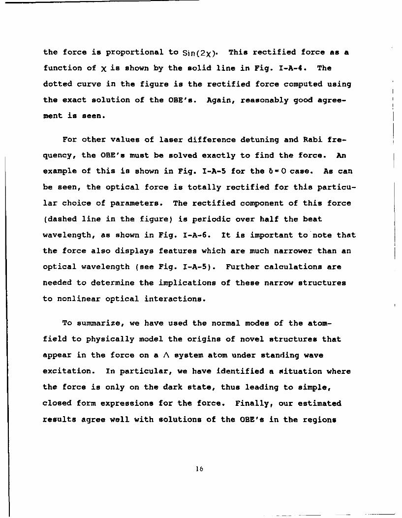
the force is proportional to Sin(2X). This rectified force as a
function of X is shown by the solid line in Fig. I-A-4. The
dotted curve in the figure is the rectified force computed using
the exact solution of the OBE's. Again, reasonably good agree-
ment is seen.
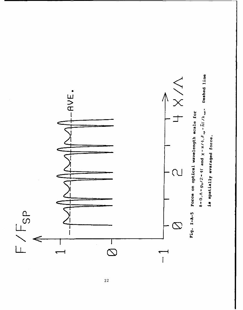
For other values of laser difference detuning and Rabi fre-
quency, the OBE's must be solved exactly to find the force. An
example of this is shown in Fig. I-A-5 for the 6 -0 case. As can
be seen, the optical force is totally rectified for this particu-
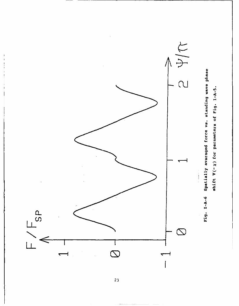
lar choice of parameters. The rectified component of this force
(dashed line in the figure) is periodic over half the beat
wavelength, as shown in Fig. I-A-6. It is important to note that
the force also displays features which are much narrower than an
optical wavelength (see Fig. I-A-5). Further calculations are
needed to determine the implications of these narrow structures
to nonlinear optical interactions.
To summarize, we have used the normal modes of the atom-
field to physically model the origins of novel structures that
appear in the force on a A system atom under standing wave
excitation. In particular, we have identified a situation where
the force is only on the dark state, thus leading to simple,
closed form expressions for the force. Finally, our estimated
results agree well with solutions of the OBE's in the regions
16
where the approximations used are valid.
References -- part I-A
[1] P.R.Hemmer, G.P.Ontai and S.Ezekiel, JOSAB 3, 219 (1986)
[2] P.R. Hemmer, M. G. Prentiss, JOSAB 5, 1613 (1988)
[3] P.R.Hemmer, M.S.Shahriar, V.D.Natoli and S.Ezekiel, JOSAB 6,
1519 (1989)
17
w000
.44
p.4
U
.4.4
0
0
0
0
0
0
UoJ 0
000w
4.-:-� '4.4
uO ** U *CU p .4*4 �
0 "�(\JA � 0
�I) *�
'-44 iO
4
* - 9* 4
* 4
* 4 .44
* 4
*
*'V 3 0
iS
$40
".4
>1 45
P44
X 00 4j
14) 1
0
A) 0
* ~ 019
.4
a 6
- 4
0P.4 t r
0 -
a b w* -4" P4 w'. a .4
Li4 w~ 1 4 6
0 *06-- -P4 a 30 41 0 -4
Ie -.4 ai x
-. 43r- A3360A
- 620
41 0
04
0 1
P-4
0
* P4
33J 3 0
4121
w~1~ 44 o<
0 -
C5-0 1
CL I
* )o.
220
I)0
0
CU0 Ij�
-4
-4
00
00
OU4.4 U)o E
#4.4 0'.4
'.4 0EU
0 �
--.40
4)4) '4.4EU0�CC 0
-4
0�Cl) -4
LL
LL� I I�-1 0
23
(B) First Observation of Deflection and Cooling of Three-
level Atoms in Raman Resonant Standing Wave Optical
Here we show experimental verification of the existence of
the long range component of the force on three-level atoms by
deflecting an atomic beam of sodium atoms using two Raman reso-
nant standing wave laser fields. The long range force Is defined
as the force averaged over an optical wavelength. In addition,
we show the existence of damping forces. These observations are
important for several reasons. First, the deflecting force is
stimulated, so that it can be made arbitrarily large. With the
co-existence of semiclassical dampi.ig forces, this opens the pos-
sibility of developing a neutral atom trap in which both the
damping and the restoring forces are optical. Since the
restoring force is stimulated in nature, such trap would be
possibly much deeper than the magneto-optic trap, wherein the
restoring force is spontaneous. Second, the Raman interaction
tends to drive atoms into the transparent (or "dark") state[l,2].
Atoms in a Raman trap would therefore be mostly in the ground
states, so that the collisional lifetime of the atoms would be
much longer than in magneto-optic traps. As a result, the Raman
force may ultimately lead to high densities of cold and dark
24
atoms in traps. Such a dense collection of atoms in transparent
superposition states could find applications as novel, low inten-
sity nonlinear optical materials[3,4].
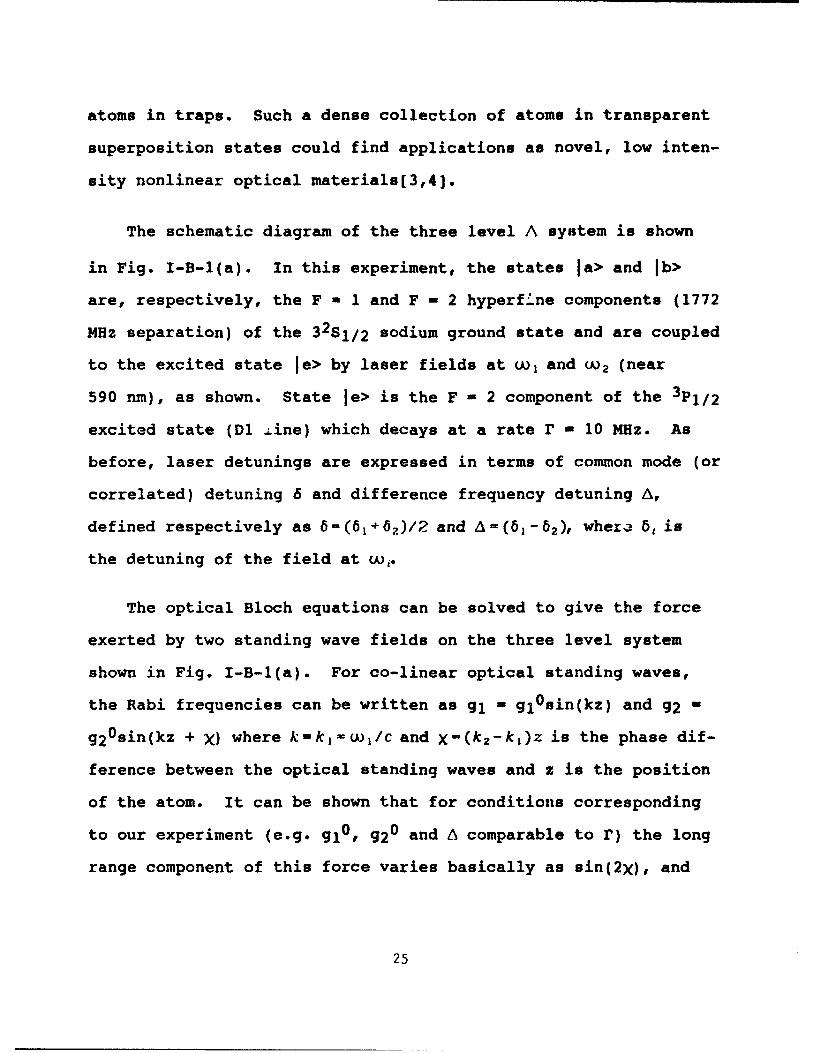
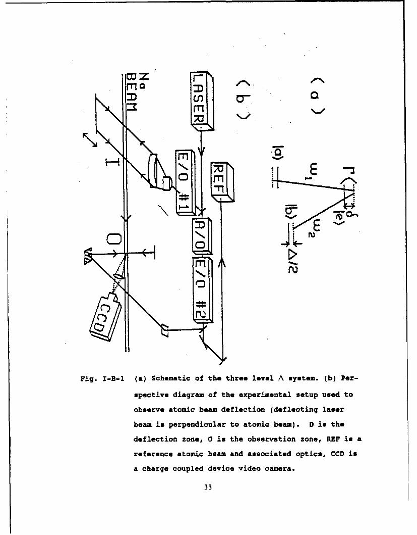
The schematic diagram of the three level A system is shown
in Fig. I-B-l(a). In this experiment, the states la> and Ib>
are, respectively, the F -1 and F - 2 hyperfi'ne components (1772
MHz separation) of the 32S1,/2 sodium ground state and are coupled
to the excited state le> by laser fields at uu, and w2 (near
590 nm), as shown. State le> is the F - 2 component of the 3 P,/2
excited state (Dl Ane) which decays at a rate r - 10 MHz. As
before, laser detunings are expressed in terms of common mode (or
correlated) detuning 6 and difference frequency detuning A,defined respectively as 6=(61+6.)/2 and A(6 1 -6 2 ), wher. b6 is
the detuning of the field at uw,.
The optical Bloch equations can be solved to give the force
exerted by two standing wave fields on the three level system
shown in Fig. I-B-1(a). For co-linear optical standing waves,
the Rabi frequencies can be written as gl - gl 0 sin(kz) and g2 -
g20 sin(kz + X) where k-kj-w 1 /c and X-(k 2 -kl)z is the phase dif-
ference between the optical standing waves and z is the position
of the atom. It can be shown that for conditions corresponding
to our experiment (e.g. gl0 g2 0 and A comparable to r) the long
range component of this force varies basically as sin(2X), and
25
its sign is proportional to the sign of A. Thus, the force is
anti-symmetric with respect to A, zero when X - nn/2 (n is any
integer), and anti-symmetric with respect to X about these zeros.
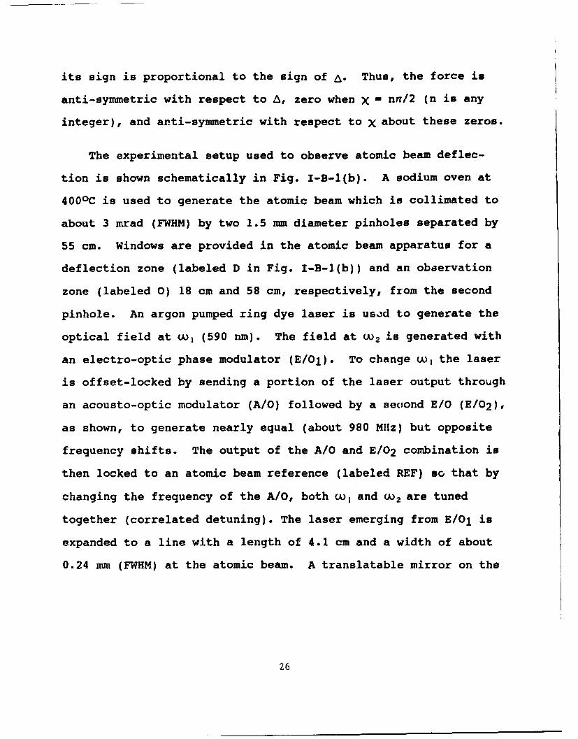
The experimental setup used to observe atomic beam deflec-
tion is shown schematically in Fig. I-B-1(b). A sodium oven at
4000C is used to generate the atomic beam which is collimated to
about 3 mrad (FWHM) by two 1.5 mm diameter pinholes separated by
55 cm. Windows are provided in the atomic beam apparatus for a
deflection zone (labeled D in Fig. I-B-1(b)) and an obaervation
zone (labeled 0) 18 cm and 58 cm, respectively, from the second
pinhole. An argon pumped ring dye laser is used to generate the
optical field at w, (590 nm). The field at w 2 is generated with
an electro-optic phase modulator (E/01). To change w, the laser
is offset-locked by sending a portion of the laser output through
an acousto-optic modulator (A/O) followed by a second E/O (E/0 2 ),
as shown, to generate nearly equal (about 980 M1Hz) but opposite
frequency shifts. The output of the A/0 and E/0 2 combination is
then locked to an atomic beam reference (labeled REF) so that by
changing the frequency of the A/O, both w, and w. are tuned
together (correlated detuning). The laser emerging from E/O1 is
expanded to a line with a length of 4.1 cm and a width of about
0.24 mm (FWHM) at the atomic beam. A translatable mirror on the
26
opposite side of the atomic beam retroreflects the deflecting
laser beam. Maximum laser power (all frequencies) in the incom-
ing deflecting beam is about 70 mW.
To detect the atomic beam deflection, a portion of the ref-
erence laser beam (from the A/O and E/O combination) is split off
to form a standing wave probe field which intersects the atomic
beam in the observation region. To avoid Doppler shifts the
probe beam is made perpendicular to both the deflecting laser
beam and the atomic beam. Fluorescence generated by this probe
field is imaged onto a CCD video camera, as shown.
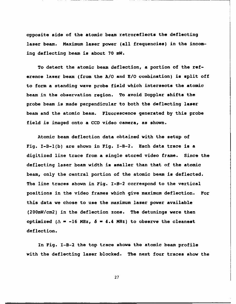
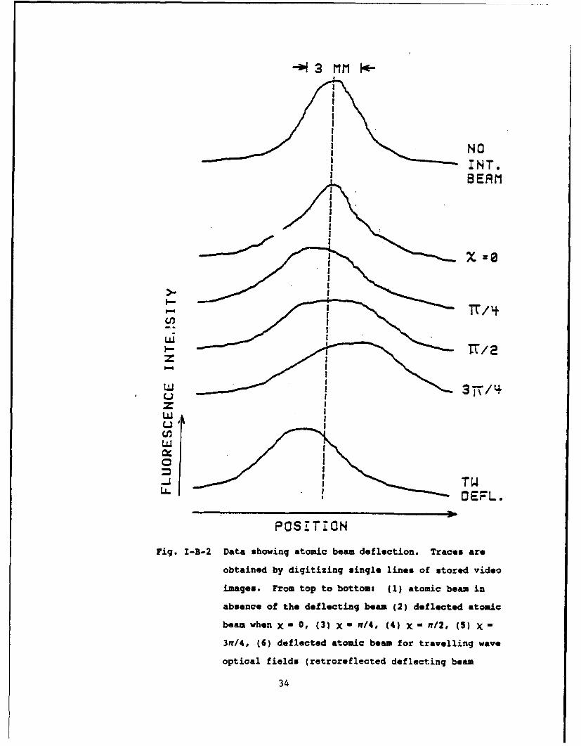
Atomic beam deflection data obtained with the setup of
Fig. I-B-1(b) are shown in Fig. I-B-2. Each data trace is a
digitized line trace from a single stored video frame. Since the
deflecting laser beam width is smaller than that cof the atomic
beam, only the central portion of the atomic beam is deflected.
The line traces shown in Fig. I-B-2 correspond to the vertical
positions in the video frames which give maximum deflection. For
this data we chose to use the maximum laser power available
(200mW/cm2) in the deflection zone. The detunings were then
optimized (A - -16 MHz, 6 - 4.4 MHz) to observe the cleanest
deflection.
In Fig. I-B-2 the top trace shows the atomic beam profile
with the deflecting laser blocked. The next four traces show the
27
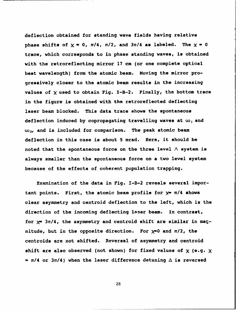
deflection obtained for standing wave fields having relative
phase shifts of X - 0, n/4, n/2, and 3n/4 as labeled. The X - 0
trace, which corresponds to in phase standing waves, is obtained
with the retroreflecting mirror 17 cm (or one complete optical
beat wavelength) from the atomic beam. Moving the mirror pro-
gressively closer to the atomic beam results in the increasing
values of X used to obtain Fig. I-B-2. Finally, the bottom trace
in the figure is obtained with the retroreflected deflecting
laser beam blocked. This data trace shows the spontaneous
deflection induced by copropagating travelling waves at wI and
w 2, and is included for comparison. The peak atomic beam
deflection in this case is about 5 mrad. Here, it should be
noted that the spontaneous force on the three level A system is
always smaller than the spontaneous force on a two level system
because of the effects of coherent population trapping.
Examination of the data in Fig. I-B-2 reveals several impor-
tant points. First, the atomic beam profile for , n/4 shows
clear asymmetry and centroid deflection to the left, which is the
direction of the incoming deflecting laser beam. In contrast,
for X- 30/4, the asymmetry and centroid shift are similar in mag-
nitude, but in the opposite direction. For )C-0 and n/2, the
centroids are not shifted. Reversal of asymmetry and centroid
shift are also observed (not shown) for fixed values of X (e.g. X
- n/4 or 3n/4) when the laser difference detuning A is reversed
28
in sign. However, for the Raman travelling waves the deflection
is not reversed. These observations are in agreement with theo-
retical predictions.
Quantitative comparison of the magnitudes of the observed
deflections in Fig. I-B-2 with theory is difficult for two rea-
sons: First, sodium is not a pure three level system but rather
has 13 m-levels with 21 allowed optical transitions for the laser
polarization and magnetic field orientation used in this experi-
ment. Since each optical transition has a different matrix ele-
ment, different Rabi frequencies apply. Second, the observed
peak deflection angle (when X - n/4 or 3n/4) is about 4 mrad,
which corresponds to a final transverse velocity of about 280
cm/s or a Doppler shift of about r/2 - 5 MHz. Since this is
comparable to A, g, and r, the v = 0 assumption used to derive
the theoretical force is not strictly valid. Nonetheless, to get
an idea about the size of the deflection, we have used the v-0
approximation to find the force for a representative transition
( 2 S1/2,F=1,mF=0 -- > 2 P1/2,F-2,mF-1 -- > 2 S,/2,F-2,mF-0). Assuming
this force to remain constant over the deflection zone, we find a
maximum deflection (at )( n/4 or 3n/4) of 5.6 mrad, which is
consistent with the observed maximum deflection of about 4 mrad.
As we have pointed out, the deflection force changes sign
when the sign of A is reversed. This property can be of help in
29
designing an all optical trap. Briefly, one can conceivably
design a B-field gradient such that the value of A is anti- sym-
metric with respect to the zero field point , which would be the
trap center. The dimension of the trap is to be small enough
(compared to 17cm) so that the value of X remains a constant
(e.g., 3n/4). The deflection force would thus always push the
atoms towards the trap center, thus acting as a restoring force.
Generalizing this scheme to three dimensions is of course a non-
trivial problem. However, three dimensional generalizations have
been found for the case of travelling wave Raman excitations,
which can possibly be extended to the standing wave scheme.
Of course, in order for such a trap to work, one would need
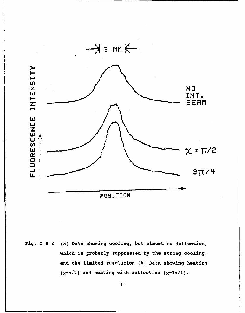
a mechanism of cooling. To this end, Fig. I-B-3 shows a set of
traces obtained under conditions optimized for cooling. The
laser intensity here is the same as that in Figs I-B-2, while the
detunings are different (A--3MHz, 6-10.6 MHz). As before, the
top trace corresponds to the atomic beam profile with the
deflecting beam blocked. The other traces display cooling for
two representative phases, X(-n/2 and )C-3n/4. Note that the cool-
ing is more prominent at C-3f/4. To interpret how strong this
cooling is, note that according to the collimation geometry
mentioned before, a beam cooled to nearly zero transverse temper-
ature would have a width (FWHM) of about 2.0 mm, which is roughly
the width of the beam at C-3n/4. This implies strong cooling at
30
this phase. An accurate measurement of the amount of cooling
therefore would require a beam which is significantly more colli-
mated. We should also point out that such a strong cooling, and
the lack of resolution, would tend to mask the observation of the
deflecting force that exists at this value according to our
theory of v-0 force.
Comparing Fig. I-B-2 with Fig. I-B-3, we find that the opti-
mum deflection and optimum cooling happen for different set of
detunings. However, the maximum deflection and the maximum
cooling happen at the same phase. Moreover, the cooling is opti-
mum for a smaller value of A, which would be nearer to the center
of the aforementioned trap. On the other hand, the deflection
force is optimum for bigger values of A, which would be away from
the center. Thus, even though we do not have any direct evidence
of cooling and deflection present at the same time, the trap
proposed above should in principle work.
In summary, we have observed the phase dependent deflection
of a sodium atomic beam by two standing waves, nimultaneously
near resonance with both components of a A three level system.
Qualitative agreement between theory and experiment is achieved,
even though sodium is not a pure three level system and the sta-
tionary atom assumption is violated. In addition, we have
observed phase dependent cooling, being maximum at the phase
31
where the deflection is maximum. Potential applioations to high
density, dark atom traps are currently being investigated. Such
dark atom traps may be useful in nonlinear optics.
References -- part I-B
[1] M. G. Prentiss, N. Bigelow, M. S. Shahriar, P. R. Hemner, K.
Berggren, J. Mervis, S. Ezekiel, Enrico Fermi International
School of Physics Course CXVIII, "Laser manipulation of
Atoms and Ions," Milan, Italy (July 1991).
[2] P. R. Hemmer, M. G. Prentiss, M. S. Shahriar, N. P. Bigelow,
Opt. Comm., accepted.
[3] M. S. Shahriar, P. R. Hemmer, Phys. Rev. Lett., 65, 1865
(1990).
[4] J. Donoghue, M. Cronin-Golomb, J. S. Kane, P. R. Hemmer,
Opt. Lett., 16, 1313 (1991).
32
WZ --
CO Z
M 4
Sr
,woo CE
pig. I-B-I (a) Schematic of the three level A system. (b) Per-
spective diagram of the experimental setup used to
observe atomic beam deflection (deflecting laser
beam is perpendicular to atomic beam). D is the
deflection zone, 0 is the observation zone, REF is a
reference atomic beam and associated optics, CCD is
a charge coupled device video camera.
33
- 3 MrM i4-
NOINT.BEAM
iT/4I
LU
I-
OEFL
Cz
POSITION
Fig. I-B-2 Data showing atomic beam deflection. Traces are
obtained by digitizing single lines of stored video
images. From top to bottom: (1) atomic beam in
absence of the deflecting beam (2) deflected atomic
beam when X" -O, (31 X - a/4, (4) X" -n/2, (S) X -
3a/4, (6) deflected atomic beam for travelling wave
optical fields {retroreflected deflecting beam
34
p-
Z NOLu INTOi-- z ~BERM'
zLU
LL zTT/2
POSITION
Fig. I-B-3 (a) Data showing cooling, but almost no deflection,
which is probably suppressed by the strong cooling,
and the limited resolution (b) Data showing heating
()C=n/2) and heating with deflection ()Cw3n/4).
35
(II) Microwave-Phase-Dependent Optical Absorption
It is well known[l] that in a laser excited resonant Raman
interaction atoms are optically pumped into a pure dressed state,
the so-called trapped state, which is transparent to the optical
excitation fields. In atomic sodium, this trapped state consists
of a linear combination of hyperfine sublevels, having a micro-
wave frequency separation. We have demonstrated that in the
presence of a resonant microwave field, the Raman trapped state
translates into one or the other microwave spin-locked (dressed)
state, under appropriate experimental conditions. Analogously,
we have shown that a microwave field can also be used to excite
the optical Raman trapped state.
Dressed states have been observed before in the microwave[2]
and visible wavelength[3] regimes using excitation field phase
shifting methodr, In addition, the optical Raman trapped state
was first observed indirectly, as a fluorescence reduction[4].
However, this is the first time a double optical (Raman) interac-
tion has been employed to excite the dressed state of a single
photon (microwave) interaction, and vice versa. This effect is
of fundamental interest because it allows optical absorption to
be modified by a change of only the phase of a miorowave field.
Such a phase dependent optical/microwave absorption has numerous
potential applications, as will be described later.
36
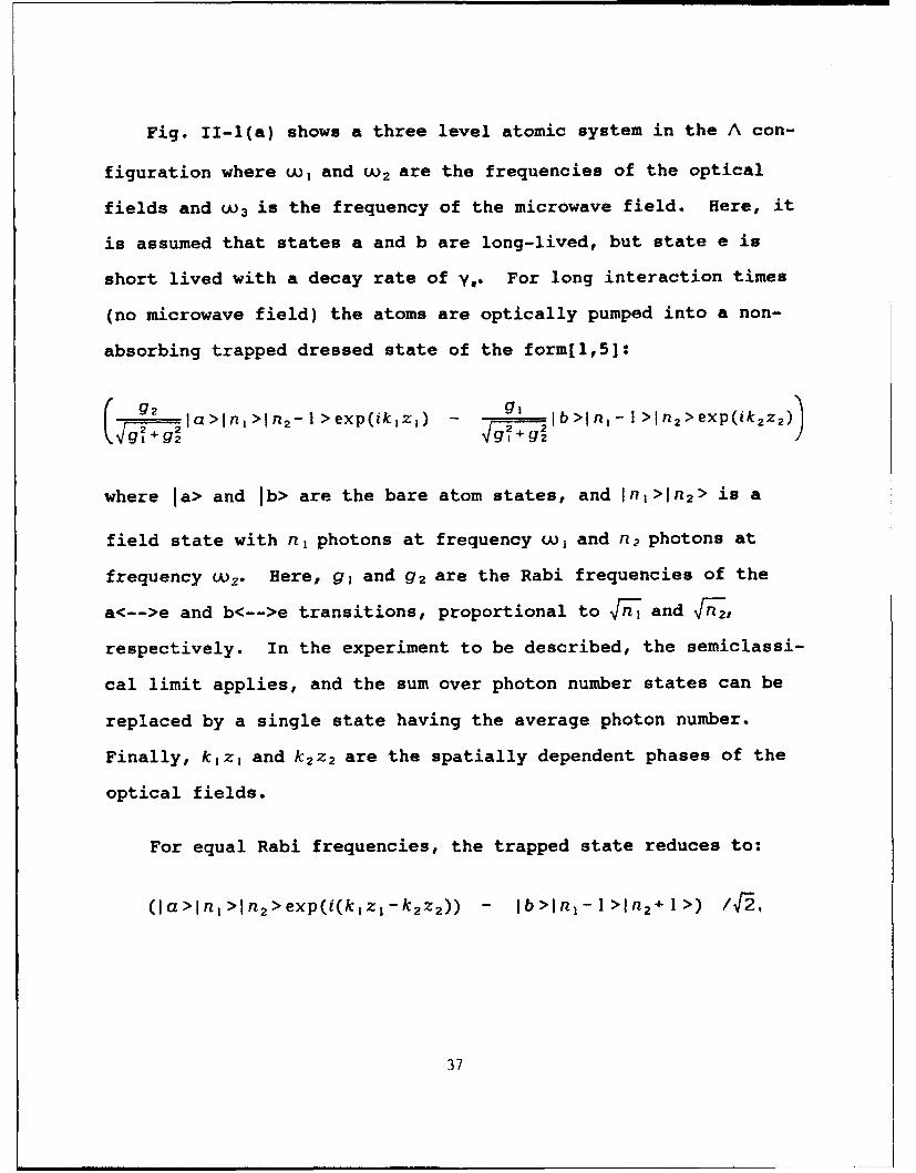
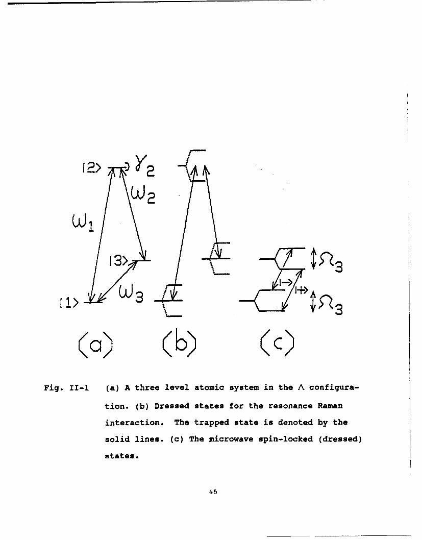
Fig. II-1(a) shows a three level atomic system in the A con-
figuration where uuI and Wo2 are the frequencies of the optical
fields and W 3 is the frequency of the microwave field. Here, it
is assumed that states a and b are long-lived, but state e is
short lived with a decay rate of y0. For long interaction times
(no microwave field) the atoms are optically pumped into a non-
absorbing trapped dressed state of the form[1,5]:
92 la>.n,-I>nn 2 1>exp ikjz+ - 1I b>1n , -1>1n 2 >exp(ik2 z 2 )
where la> and lb> are the bare atom states, and Jn1 >ln 2 > is a
field state with nj photons at frequency w, and n 2 photons at
frequency wu. Here, g, and g 2 are the Rabi frequencies of the
a<-->e and b<-->e transitions, proportional to • and •,
respectively. In the experiment to be described, the semiclassi-
cal limit applies, and the sum over photon number states can be
replaced by a single state having the average photon number.
Finally, kjzj and k 2 z 2 are the spatially dependent phases of the
optical fields.
For equal Rabi frequencies, the trapped state reduces to:
(la>1nj>In 2 >exp(i(kjzj-k2zz2 )) - Ib>ln 1 -1>In 2 +1>) 4-2,
37
where the phase exp(ik 2z 2 ) has been factored out. In comparison,
the high and low energy dressed states of the a<-->b microwave
transitions are
(la>ln 3 >exp(-ik 3z 3 ) - )b>1n 3 -1>) 4_2
and
(ja>1n3>exp(-ik3Z3) + lb>In3-]I> /F2.,
respectively, where W3 is the microwave frequency, and the semi-
classical limit is again assumed.
To help clarify the physics involved, consider a stepwise
process wherein the optical Raman interaction and the microwave
interaction are separated in time. First, the optical Raman
interaction puts the atoms into the trapped state, as illustrated
in Fig. II-1(b). Next, the laser fields are turned off and a
microwave field is turned on. In general, two microwave dressed
states are possible, as shown by the energy level diagram of
Fig. II-l(c). To determine into which microwave eigenstate the
Raman trapped state evolves, it is necessary to know the relative
phase of the microwave and the double optical (Raman) fields.
This relative phase is given by
*-[(kI z I - k2z 2 )-k 3Z3 ],
38
where it is assumed that all three states are in phase at
ZI Z2 Z3--0.
When the laser diffeience frequency is exactly in (or out
of) phase with the microwave frequency, i.e., * - 0 (or
* - n), the Raman trapped state translates directly into the
high (or low) energy microwave dressed state. For any other
value of the relative phase *, a linear combination of microwave
dressed states results. In such a case, Rabi spin flips occur[6J
(largest for ý = n/2), partially destroying the original
dressed state. To detect the degree of microwave interaction,
the microwave field can be turned off and the Raman interaction
can be turned back on. Population lost from the trapped state
would then appear as an increase in optical absorption.
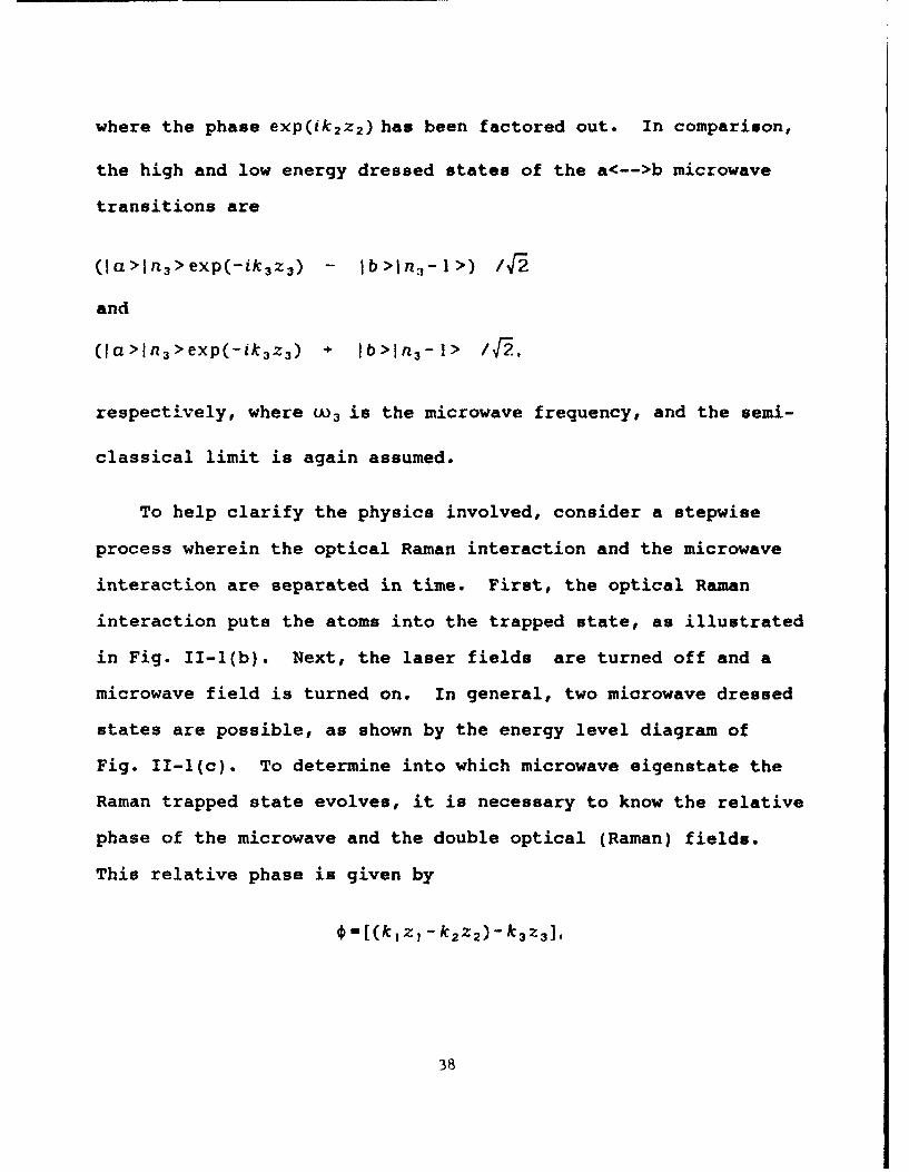
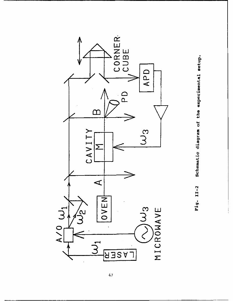
Experimentally, this three step process can be realized
using a separated field excitation scheme in an atomic beam. The
experimental setup we used is illustrated schematically in
Fig. 11-2. Here, a sodium oven is operated at about 4000C to
generate a thermal atomic beam. The laser field at frequency w,
(590 nmi is the output of a cw dye laser having 1 MHz of fre-
quency jitter. To minimize the effect of this jitter[7], the
field at frequency Uw2 is generated from that at w 1 by using an
acousto-optic modulator (A/O). The A/0 is driven by a quartz
stabilized microwave oscillator at the a<->b transition frequency
39
(1772 MHz). The laser fields at Lu, and U 2 are made copropagat-
ing to a high degree of precision by coupling both through a
common single mode optical fiber (not shown). In this
experiment, states Ia> and lb> are the F-i and F-2 hyperfine
sublevels, respectively, of the 2SI/ 2 ground state, and state le>
is the F=2 sublevel of the 2 P,/2 state. The laser beams in zones
A and B are right circularly polarized, and a dc magnetic holding
field of 0.3 Gauss is applied parallel to the laser propagation
direction, to lift the degeneracy of the Zeeman sublevels. The
m=0, Am =0 Raman transition is used. For the microwave exci-
tation, A TE201 rectangular resonant cavity is used in an orien-
tation which excites the mO-. Am=O transition.
First, Raman excitation in zone A first pumps the atoms into
the trapped state. Then, these atoms interact with a microwave
field, zone M. The Raman probing interaction in zone B measures
the degree of the microwave interaction by detecting any loss of
the trapped state population, via the fluorescence detecting pho-
todiode (PD). The pathlengths to zones A and B are set so that
the optical difference frequencies in zones A and B are in
phase[7]. The microwave field is generated by detecting and
amplifying the beat between the two optical fields using a 2 GHz
avalanche photo diode (APD). This ensures that the microwave and
the double optical fields are phase locked. The relative phase
40
between the microwave and the laser difference frequencies is
controlled by changing the pathlength traversed by the laser
beams before reaching the APD.
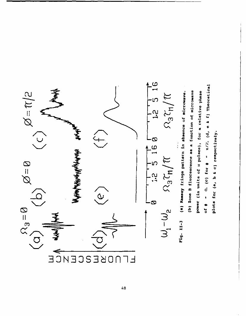
Fig. II-3(a) shows the Raman-Ramsey fringes observed in zone
B when the laser difference frequency is scanned, for zero micro-
wave power. Fig. II-3(b) shows the fluorescence observed, with
the laser difference frequency held exactly on resonance
(fluorescence minimum), but the microwave power scanned. Here,
the microwave field is exactly in phase with the optical differ-
ence frequency, i.e., 0 = 0. As can be seen, the microwave
field has no effect, since in this case the optical Raman trapped
state translates into a pure microwave spin-locked eigenstate.
Fig. II-3(c) shows the case of * = n/2, as the microwave power
is again scanned, with the laser difference frequency held on
resonance. Here, the fluorescence depends strong]y on microwave
power, undergoing large oscillations caused by Rabi spin flips,
indicating that a microwave eigenstate is no longer excited. The
damping with increasing microwave power in Fig. II-3(c) is caused
by velocity averaging effects. Comparison with the theoretical
plots of Figs. II-3(d,e,f) shows good agreement[8j. To illus-
trate what happens for phases other than f-0 or n/2,
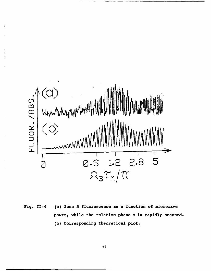
Fig. II-4(a) shows the absorption observed when the phase * is
rapidly varied while scanning the microwave power. -,re, the
41
absorption varies sinusoidally with *, and the curves of
Fig. 11-3(b) and II-3(c) form the envelope function.
Fig. II-4(b) shows the corresponding theoretical plot.
We also performed the complimentary experiment wherein a
microwave field is used to excite the optical Raman trapped
state. This involves replacing the first Raman zone in Fig. 11-2
by an optical pumping zone (not shown), which effectively puts
all the atoms into state Ib> before entering the microwave cav-
ity. For a microwave power corresponding to a n/2 pulse, the
resulting state is
(-i Ia>jn 3 >exp(-ik 3z) + Jb>In3_->) ]F.
This can be made to correspond to a Raman trapped state if the
relative phase * between the microwave and the laser difference
frequency is n/2.
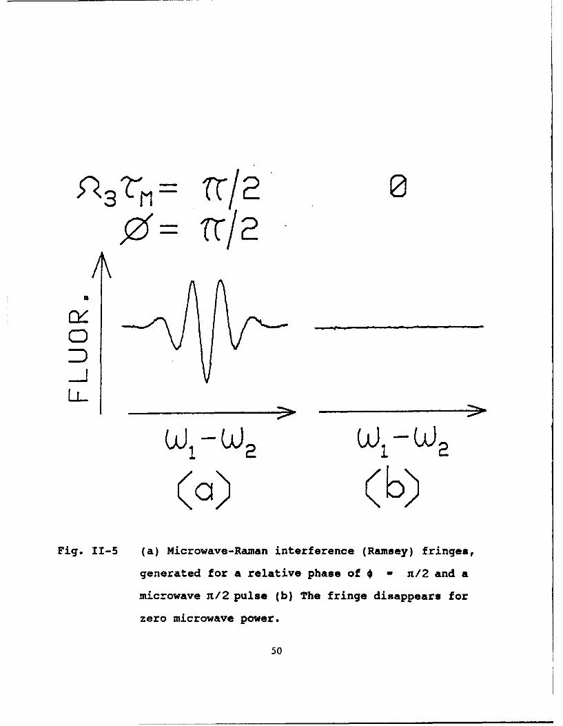
Experimental evidence of microwave excitation of an optical
Raman trapped state appears in Fig. 11-5. Here, Fig. 11-5(a)
shows the zone B fluorescence[9] obtained by scanning the laser
difference frequency with a microwave power corresponding to a
n!2 pulse and a relative phase of n - n/2. As can be seen,
Ramsey fringes are obtained which closely resemble those in
Fig. II-3(a), even though only one Raman excitation zone is pres-
ent. Thus, an optical Raman trapped state has been excited by
42
the microwave field. For completeness, Fig. II-5(b) shown the
zone B fluorescence obtained with the microwaves turned off. As
expected, no Ramsey fringes are seen in this case.
Extension of these results to a single zone excitation
scheme (where both microwave and optical Raman fields are present
simultaneously) is also of interest because of the possibility of
exciting a three photon trapped state[10]. This would occur for
a relative Raman and microwave phases of f - 0 or n. For
other values of *, all dressed states are partially optically
absorbing, where the steady state absorption depends on ý. For a
properly chosen configuration, the position dependence of the
relative phase * would result in a grating being produced, which
would diffract both optical and microwave fields. Numerous
applications of this effect can be imagined if the microwave
transition is replaced by a mm-wave or far infrared transition.
For example, real time mm-wave beam steering can be performed
wherein the mm-wave could be deflected by the optical beams. It
should also be possible to perform real time holographic far
infrared to visible image conversion(ll].
Finally, we briefly consider the effects of the finite pho-
ton number spread. Because of this spread, dressed states exist
in manifolds, each characterized by the photon number. In case
of a microwave excitation, the manifolds are not coupled due to
43
lack of spontaneous emission. Addition of the Raman field par-
tially restores the manifold. For example, a relative phase of
*-n would cause the weak field seeking microwave state to decay
to decay into the strong field seeking state at a rate which
depends on the laser intensity. This process may have applica-
tions to collision studies, laser cooling, and possibly even to
trapping of neutral atoms in a microwave cavity[12J. We are
currently investigating some of these applications potentials.
In summary, we have used a laser induced resonance Raman
transition-in a sodium beam to excite individual dressed states
of the microwave-spin hyperfine transition. Conversely, we have
also used the microwave interaction to excite the Raman trapped
state. Extension of this technique to mm-waves or to the far
infrared may lead to applications such as beam steering and image
conversion.
References -- part II
[11 H. R. Gray, R. M. Whitley, and C. R. Stroud, Jr., Opt. Lett.
3, 218 (1978).
[2] S. R. Hartmann, E. L. Hahn, Phys. Rev. 128, 2042 (1962).
[3] Y. S. Bai, A. G. Yodh, and T. W. Mossberg, Phys. Rev. Lett.
55, 1277 (1985).
44
[4] G. Alzettal A. Gozzini, L. Moil and G. Orriols, Nuovo
Cimento 36B, 5 (1976).
(51 P. M. Radmore and P. L. Knight, J. Phys. B. 15, 3405 (1982)
(6] N. F. Ramsey, Molecular Beans, (oxford U. Press, London,
1956).
171 J. E. Thomas, P. R. Hemmer, S. Ezekiel, C. C. Leiby, Jr., R.
H. Picard, and C. R. Willis, Phys. Rev. Lett. 48, 867
(1981).
(81 The microwave field amplitude scan was non-linear, as indi-
cated in the horizontal axes of Figs. 3(bcef).
[91 Lock-in detection was employed to enhance signal to noise
for this data,
110] S. J. Buckle, S. M. Barnett, P. L. Knight, M. A. Lauder, and
D. T. Pegg, Optica Acta 33, 1129 (1986)
[11] For other techniques of laser assisted far infrared to vis-
ible image conversion, see for example: V. V. Krasnikov, M.
S. Pshenichnikov, and V. S. Solomatin, Sov. J. Quan. Elec.
14, 418 (1984), and the references therein.
112] C. Agosta, I. Silvera, H. Stoof and B. Verhaar, Phys. Rev.
Lett. 62, 2361 (1989)
45
12>
13>
(a) (b(C)Fig. II-1 (a) A three level atomic system in the A configura-
tion. (b) Dressed states for the resonance Raman
interaction. The trapped state is denoted by the
solid lines. (c) The microwave spin-locked (dressed)
states.
46
uIJI~ ZLLJ
4.)
0 0
4.1
w~-04
CQ) > n3 >
30
3- 83S v -
47H
(.O -0
Cu 0if) 0 3 -.4
S a d
0(.0 0
'4 0 0
a 0 0 .04
33 33 3('4n, --- 4
48
33 ̂ ("
F--
0 0.S I.? . 5
Fig. 11-4 (a) Zone B fluorescence as a function of microwave
power, while the relative phase ý is rapidly scanned.
(b) Corresponding theoretical plot.
49
,o%3Z11~= 0
W W
(a)) (kb)Fig. 11-5 (a) Microwave-Ramnan interference (Ramsey) fringes,
generated for a relative phase of *- n/2 and a
microwave n/2 pulse (b) The fringe disappear. f or
zero microwave power.
50
(III) Optically Excited Microwave Spin Echoes
There has been much recent interest in the use of optical
photon echoes for information storage and processing[l]. How-
ever, experimental demonstrations have so far been restricted to
spectral hole burning materials operating at liquid He
temperatures. Information has been stored using microwave spin
echoes in room temperature materials[2], but the data rates and
storage densities achievable are orders of magnitude below those
of optical echo techniques. The proposed scheme, which makes use
of an optically excited microwave spin echo, is capable of data
rates and storage densities comparable to the optical echo tech-
niques, but potentially at much higher temperatures (provided a
suitable material can be found). In contrast to multilevel
optical echoes, the Raman excited microwave coherences can store
information which is spread over times much longer than the homo-
geneous decay time of the optical coherence.
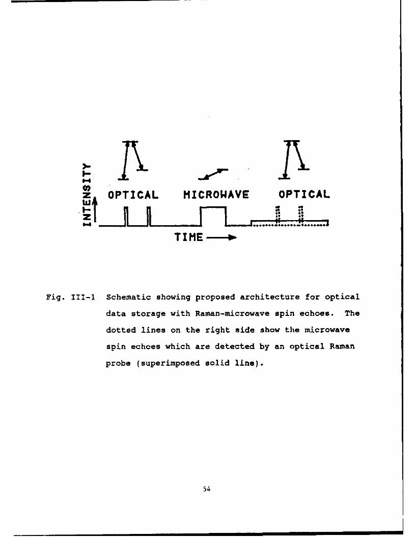
The basic architecture of the proposed scheme is illustrated
in Fig. III-1. A three level system is used, which can be
excited by two near resonant optical transitions (resonance
Raman) or one near resonant microwave transition. As shown,
information is first input as an optical pulse train (two unequal
amplitude pulses in the figure). The optical input beam contains
bo-h optical frequencies needed to excite the resonance Raman
51
transition. The Raman interaction creates a coherence which
depends on phase differences in the two optical frequencies.
This phase sensitivity, combined with dephasing of the ground
state coherence due to inhomogeneous broadening# allows both the
temporal and phase information contained in the optical fields to
be stored via a process analogous to spectral hole burning. To
recall this information, a Ti-pulse must be applied. Since the
Raman coherence directly translates into a microwave coherence[3]
this can be accomplished with a microwave n-pulse. The ground
state coherences will then rephase at the appropriate time where
they can be detected optically, as bright and dark areas, using
an optical Raman probe, as shown in Fig. III-1.
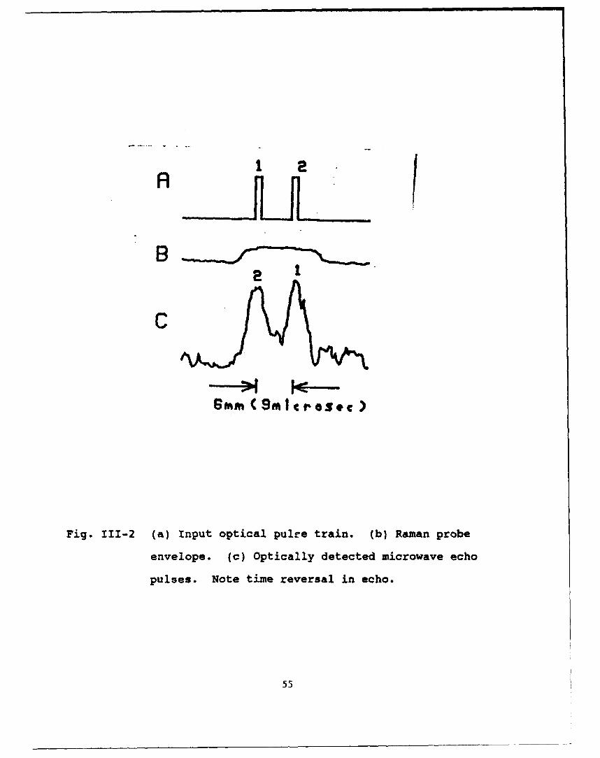
The experimental demonstration is accomplished using a
sodium atomic beam with three interaction zones. In the first
zone, two spatially separated optical Raman pulses are used, as
illustrated in Fig. III-2(a). This represents a temporal pulse
sequence because the atoms are moving. A uniform magnetic field
is aprlied in this zone, which produces an inhomogeneous broaden-
ing because of the axial velocity distribution in the thermal
atomic beam. In the second zone, a microwave n-pulse is used to
time reverse the spin coherence. The third zone consists of a
Raman probe pulse (Fig. III-2(b)) to detect the coherence opti-
cally. In order to generate the echo, a magnetic field is
applied in this zone, which is matched to that in the first zone.
52
The observed echo signal is shown in Fig. III-2(c). As shown,
the time separation between the pulses is many times larger than
the lifetime of excited sodium (16 nsec. for the D1 transition).
References -- part III
[1] M.K. Kim and R. Kachru, Opt. Lett. 12, 593 (1987)
(2] S. Fernbach and W.G. Proctor, Jour. of Appl. Phys. 2&, 170
(1955)
[3] M.S. Shahriar and P.R. Hemmer, Phys. Rev. Lett. f5, 1865
(1990)
53
z. OPTICAL MICROAVE OPTICAL
TIME--.
Fig. II1-1 Schematic showing proposed architecture for optical
data storage with Raman-microwave spin echoes. The
dotted lines on the right side show the microwave
spin echoes which are detected by an optical Raman
probe (superimposed solid line).
54
%.
8 n
C
SMAg ( 9M croSec )
Fig. 111-2 (a) Input optical pulre train. (b) Raman probe
envelope. (c) Optically detected microwave echo
pulses. Note time reversal in echo.
55
Thesis
Selim M. Shahriar, "Fundamental Studies in Three Level Atoms and
Applications," Ph.D in Electrical Engineering and Computer Sci-
ence, October 1991.
Publications
1. S. Shahriar, P.R. Hemmer, "Microwave-Phase-Dependent Optical
Absorption," in International Quantum Electronics Conference
1990 Technical Digest Series (Opt. Soc. of Am., Washington
DC) QFA6.
2. S. Shahriar, P.R. Hemmer, "Direct Excitation of Microwave-
Spin Dressed States Using a Laser-Excited Resonance Raman
Interaction," Physical Review Letters 15, 1865 (1990)
3. S. Shahriar, P. Hemmer, N. Bigelow and M. Prentiss, "Forces
on Three Level Atoms Including Trapped State Contribution,"
in Quantum Electronics and Laser Science 1991 Technical
Digest Series (Opt. Soc. of Am., Washington DC) pp 186.
4. M. G. Prentiss, N. Bigelow, M. S. Shahriar, P. R. Hemmer, K.
Berggren, J. Mervis, S. Ezekiel, Enrico Fermi International
School of Physics Course CXVIII, "Laser manipulation of
Atoms and Ions," Milan, Italy (July 1991).
56
5. M. Prentiss, N. Bigelow, S. Shahriar and N. Bigelow, "Forces
on Three Level Atoms Including Coherent Population Trap-
ping," Optics Letters, 16, 1695 (1991).
6. P. Hemmer, M. Prentiss, S. Shahriar and P. Hemmer, "Optical
Force on the Raman Dark State in Two Standing Waves,"
accepted for publication in Optics Communioations.
7. P. Hemmer, S. Shahriar, M. Prentiss, D. Katz, K. Berggren,
and J. Mervis, "Observation of the Deflection of Three Level
Atoms due to Two Standing Wave Optical Fields," Quantum
Electronics and Laser Science
Conference, 1992, accepted.
8. P. Hemmer, S. Shahriar, M. Prentiss, D. Katz, K. Berggren,
and J. Mervis, "First Observation of Forces on Three Level
Atoms in Raman Resonant Standing Wave Optical Fields"
accepted for publication in Physical Review Letters.
9. M. Prentiss, D. P. Katz, J. Mervis, K. Berggren, P. Hemmer,
S. Shahriar, N. Bigelow, "Damping and Deflection of Three
Level Atoms due to Two Standing Wave Optical Fields, and
Application to Traps," International Laser Science Confer-
ence, 1992, invited paper
57
10. S. Shahriar and P. Hemmer, "Optical Data Storage with Raman
Excited Microwave Spin Echoes," submitted to OSA Conference,
1992
*U.S. GOVERNMENT PRINTING OFFICE 199- 3710-091-f•17l
58