Embed Size (px)
Citation preview
Journal of the Serbian Society for Computational Mechanics / Vol. 4 / No. 1, 2010 / pp. 66-87
(UDC: 519.673:624.012.45.072.23)
Nonlinear Three Dimensional Finite Element Analysis of Reinforced Concrete Beams on Elastic Foundations
Dr. Adel A. Al- Azzawi 1 and Ali M. Al-Obaidie2
1Nahrian University, Baghdad, Iraq [email protected] 2Nahrian University, Baghdad, Iraq [email protected]
Abstract
The main objective of the present investigation is to carryout a nonlinear analysis of reinforced concrete beams resting on elastic foundation. Material nonlinearities due to cracking of concrete, plastic flow, crushing of concrete and yielding of reinforcement are considered. Foundation representation is assumed linear using Winkler model.
The reinforced concrete beams is modeled by using three dimensional finite elements with steel bars as smeared layers. The examples have been chosen in order to demonstrate the applicability of the modified computer program (Dynamic Analysis of Reinforced Concrete Beams on Elastic Foundations DARCEF) by comparing the predicted behavior with that from other experimental and analytical observations.
The program modified in the present research work is capable of simulating the behavior of reinforced concrete beams resting on Winkler foundation and subjected to different types of loading. The program solutions obtained for different reinforced concrete beams resting on elastic foundations are in good agreement with the available results. Maximum percentage difference in deflection is 15%.
Keywords: Deep beams , elastic foundations, finite element, reinforced concrete, three dimensional.
1. Introduction
It is a common practice to use a linear analysis for reinforced concrete structures. Both the strains and displacements developed in the structure are assumed to be small. This means that the material and geometrical nonlinearities are not taken into account; therefore the expected behavior of the member differs from the real behavior leading to approximate solutions. It is known that, plain concrete has low tensile strength, limited ductility and little resistance to crack propagation. Flaws or micro-cracks develop in concrete during its manufacture and even before any load is applied. Published papers have shown that when reinforced concrete is subjected to different types of loading it will exhibit a highly nonlinear behavior due to cracking, crushing aggregate interlock, dowel action and yielding of reinforcement.
Journal of the Serbian Society for Computational Mechanics / Vol. 4 / No. 1, 2010
67
Problem of reinforced concrete beams on elastic foundations with both compressional and frictional resistances are good examples to extend the applications to foundations. In these problems, the compressional resistances of the elastic medium to the bottom face of the beams are determined by considering the linear relationships of the normal displacement to the compressional reactions (Winkler model). The frictional restraints are modeled by considering the linear relation to the horizontal displacement (Winkler model).
Winkler (1867) proposed the first model of beam on an elastic foundation based on pure bending beam theory, later Pasternak in 1954 proposed the shear model based on the assumption of pure shear of the beam. Both of these two models take an extreme point of view on the deformation behavior of the beam. Timoshenko in 1921 proposed models for the vibration of deep beams; his beam theory still attracts people's attention for studying the static and dynamic responses of deep beams (Bowles 1974).
Biot (1937) considered the problem of bending, under a concentrated load, of infinite flexible beams on a homogeneous elastic-isotopic subgrade.
Levinson (1949) suggested that the contact pressure is represented by a number of redundant reactions which would create a set of simultaneous equations in terms of pressures diagram coordinates and elasticity constants.
Terzaghi (1955) established a number of equations to calculate the modulus of subgrade reaction for cohesive and cohesionless soils, depending on plate load test results.
Cheung and Nag (1968) studied the effects of separation of contact surfaces due to uplift forces. In addition, they have enabled the prediction of the bending and torsion moments in the plate sections by adopting three degrees of freedom per node.
Bowles (1974) developed a computer program to carry out the analysis of beams on elastic foundation by using the finite element method, in which Winkler model is adopted to represent the elastic foundation.
Selvadurai (1979) presented a theoretical analysis of the interaction between a rigid circular foundation resting on elastic half space and a distributed external load of finite extent which acts at an exterior region of the half space.
Yankelevsky et al. (1988) presented an iterative procedure for the analysis of beams resting on nonlinear elastic foundation based on the exact solution for beams on a linear elastic foundation.
Yin (2000) derived the governing ordinary differential equation for a reinforced Timoshenko beam on an elastic foundation.
Guo and Wietsman (2002) made an analytical method, accompanied by a numerical scheme, to evaluate the response of beams on the space-varying foundation modulus, which is called the modulus of subgrade reaction (Kz=Kz(x)).
2. Material modeling
2.1 Numerical modeling of concrete
The numerical modeling of concrete, which is used in the nonlinear finite element program, includes the following:
A stress-strain model to represent the behavior of concrete in compression.
Adel A. Al- Azzawi and Ali M. Al-Obaidie: Nonlinear Three Dimensional Finite Element Analysis …
68
Failure criteria to simulate cracking and crushing types of fracture.
A suitable crack representation model.
A post-cracking stress-strain relationship.
2.1.1 Stress-strain models for concrete in compression
Because of the complex behavior of reinforcement and concrete under general load, a mathematical description of the material properties of concrete is established by using suitable constitutive equations. Several models have been proposed to define the complicate stress-strain behavior of concrete in compression under various stress states (Chen 1982). These models can be generally classified into:
Elasticity based models.
Plasticity based models.
2.1.2 Modeling of concrete fracture
Fracture of concrete can be classified as crushing or cracking. The crushing type of fracture is defined by progressive degradation of the material internal structure under compressive stresses. The cracking type of fracture is characterized by a general growth of micro-cracks which join together to form a failure plane.
In general, two different methods were employed to represent the cracks in the finite element analysis of concrete structures. These are the discrete crack representation and the smeared cracks representation.
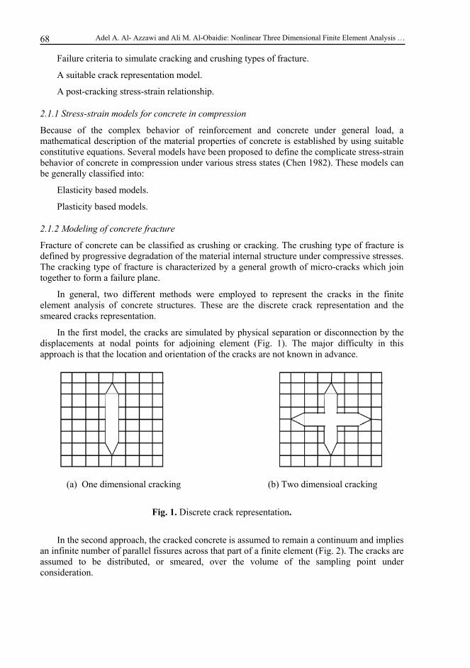
In the first model, the cracks are simulated by physical separation or disconnection by the displacements at nodal points for adjoining element (Fig. 1). The major difficulty in this approach is that the location and orientation of the cracks are not known in advance.
(a) One dimensional cracking (b) Two dimensioal cracking
Fig. 1. Discrete crack representation.
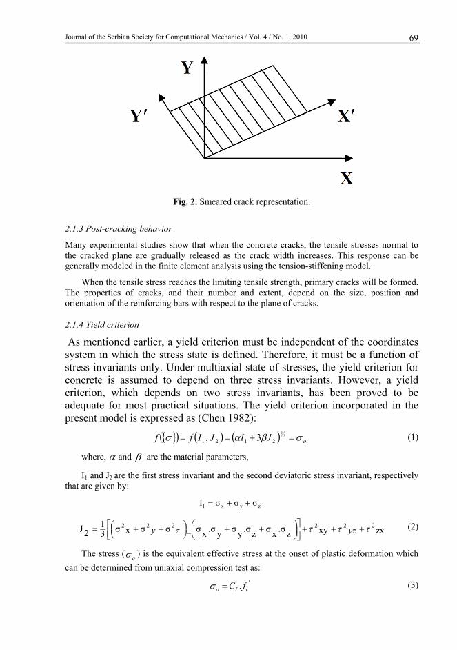
In the second approach, the cracked concrete is assumed to remain a continuum and implies an infinite number of parallel fissures across that part of a finite element (Fig. 2). The cracks are assumed to be distributed, or smeared, over the volume of the sampling point under consideration.
Journal of the Serbian Society for Computational Mechanics / Vol. 4 / No. 1, 2010
69
Fig. 2. Smeared crack representation.
2.1.3 Post-cracking behavior
Many experimental studies show that when the concrete cracks, the tensile stresses normal to the cracked plane are gradually released as the crack width increases. This response can be generally modeled in the finite element analysis using the tension-stiffening model.
When the tensile stress reaches the limiting tensile strength, primary cracks will be formed. The properties of cracks, and their number and extent, depend on the size, position and orientation of the reinforcing bars with respect to the plane of cracks.
2.1.4 Yield criterion
As mentioned earlier, a yield criterion must be independent of the coordinates system in which the stress state is defined. Therefore, it must be a function of stress invariants only. Under multiaxial state of stresses, the yield criterion for concrete is assumed to depend on three stress invariants. However, a yield criterion, which depends on two stress invariants, has been proved to be adequate for most practical situations. The yield criterion incorporated in the present model is expressed as (Chen 1982):
21
2121 3, JIJIff (1)
where, and are the material parameters,
I1 and J2 are the first stress invariant and the second deviatoric stress invariant, respectively that are given by:
zyx1 σσσI
zxxyz.σ
xσ
z.σ
yσ
y.σ
xσ_σσxσ3
12J 222222
yzzy (2)
The stress ( ) is the equivalent effective stress at the onset of plastic deformation which
can be determined from uniaxial compression test as:
'. cP fC (3)
Adel A. Al- Azzawi and Ali M. Al-Obaidie: Nonlinear Three Dimensional Finite Element Analysis …
70
The coefficient (Cp) is the plasticity coefficient, which is used to mark the initiation of plasticity deformation.
The material parameters and can be determined from the uniaxial compression test
and biaxial test under equal compressive stresses. The parameters and have been found to
be (0.35468) and (1.35468) respectively and equation (1) can be rewritten as:
2/121 32 JIcf (4)
where,
7734.12/ c (5)
Equation (4) can be solved for ( ) as:
21
22
11 3 JcIcIf (6)
The hardening rule is necessary to describe the motion of the loading surfaces during plastic deformation. In the present study an isotropic hardening rule is adopted. Therefore, equation (6) can be expressed for the subsequent loading functions as:
*2
211
21
3 JcIcIf (7)
where,
* represents the stress level at which further plastic deformation will occur and is termed as the effective stress or the equivalent uniaxial stress. The incremental theory of plasticity implies a relationship between the effective stress and the effective plastic strain to extrapolate the results of a uniaxial state of stress to multiaxial states.
The effective, accumulated, plastic strain, p , can be calculated by integrating the effective
plastic strain increment, pd , along the strain path as:
pp d (8)
The effective plastic strain increment may be determined using the work hardening hypothesis as:
**
.
pp
p
ddwd (9)
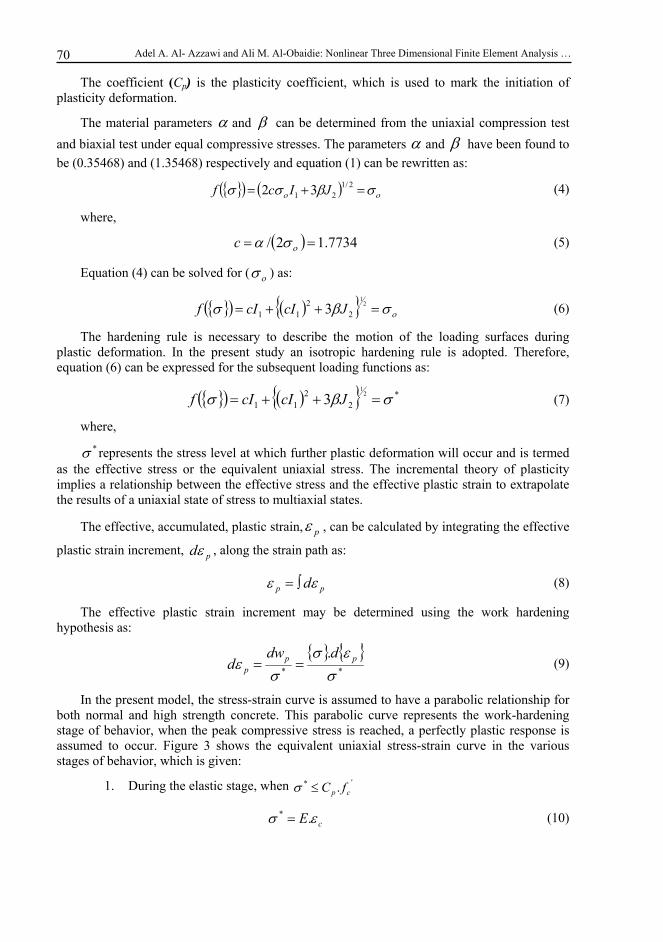
In the present model, the stress-strain curve is assumed to have a parabolic relationship for both normal and high strength concrete. This parabolic curve represents the work-hardening stage of behavior, when the peak compressive stress is reached, a perfectly plastic response is assumed to occur. Figure 3 shows the equivalent uniaxial stress-strain curve in the various stages of behavior, which is given:
1. During the elastic stage, when '* . cp fC
cE .* (10)
Journal of the Serbian Society for Computational Mechanics / Vol. 4 / No. 1, 2010
71
2. After the initial yield, and up to the peak concrete compressive strength, when '*'. ccp ffC , then
E
fCE
E
fCEfC cp
ccp
ccp
'
'
''* .
.2
..
(11)
3. Beyond the peak stress, when ' c
'*cf (12)
where, ' , is the total strain corresponding to the parabolic part of the curve given by:
EfC cp .12' (13)
Fig. 3. Equivalent effective stress-strain curve for concrete.
In the present study, values of 0.3 and 0.5 are assumed for plastic coefficient Cp for the normal and high strength concrete respectively, and the plastic yielding begin at a stress level of Cp fc
'(Al-Ani, 2000). If Cp=1.0, then the elastic perfectly plastic behavior is specified (Fig. 3).
2.2 Modeling of reinforcement
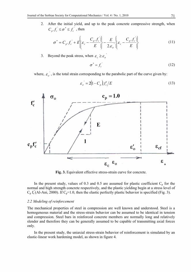
The mechanical properties of steel in compression are well known and understood. Steel is a homogeneous material and the stress-strain behavior can be assumed to be identical in tension and compression. Steel bars in reinforced concrete members are normally long and relatively slender and therefore they can be generally assumed to be capable of transmitting axial forces only.
In the present study, the uniaxial stress-strain behavior of reinforcement is simulated by an elastic-linear work hardening model, as shown in figure 4.
Adel A. Al- Azzawi and Ali M. Al-Obaidie: Nonlinear Three Dimensional Finite Element Analysis …
72
Fig. 4. Stress strain relationship of steel bar.
3. Finite element representation
The finite element idealization of reinforced concrete is necessary for the application to reinforced concrete beams under static loads. In the present study, concrete is simulated by brick elements, and reinforcement bars are modeled as a smeared layer (Al-Obaidie 2005).
3.1 Concrete representation
The 20-node isoparametric quadratic brick element is used in the present study to represent the concrete.
3.1.1 Displacement representation
The displacement field within the element is defined in terms of the shape functions and displacement values at the nodes. Each nodal point has three degrees of freedom u, v and w along the Cartesian coordinates x, y and z, respectively.
Therefore, for each element the displacement vector is:
202020222111 ,,.........,,.........,,,,, wvuwvuwvua (14)
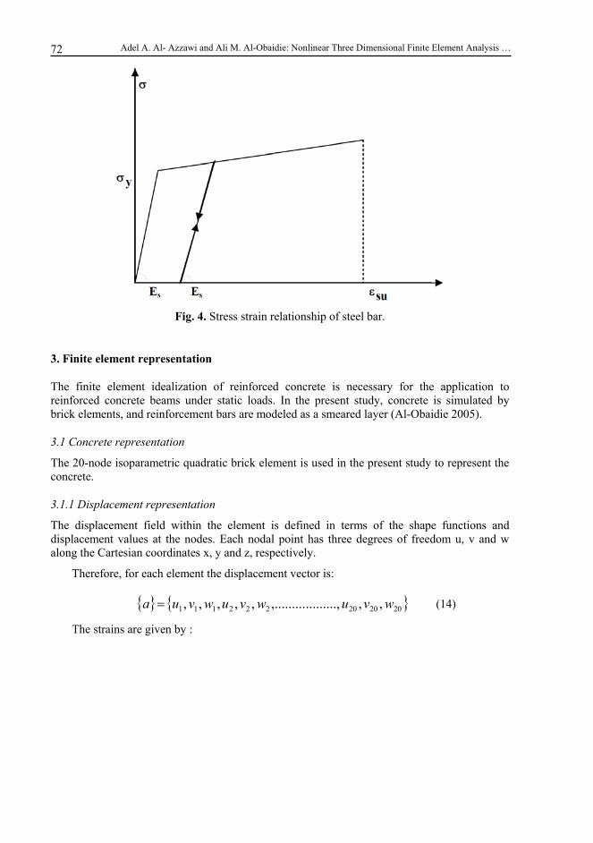
The strains are given by :
Journal of the Serbian Society for Computational Mechanics / Vol. 4 / No. 1, 2010
73
i
i
i
i
ii
ii
ii
i
i
i
xz
yz
xy
z
y
x
w
v
u
z
N
x
Ny
N
z
Nx
N
y
Nz
Ny
Nx
N
.
0
0
0
00
00
00
20
1
(15)
or
aB (16)
where, [B] is the strain displacement matrix.
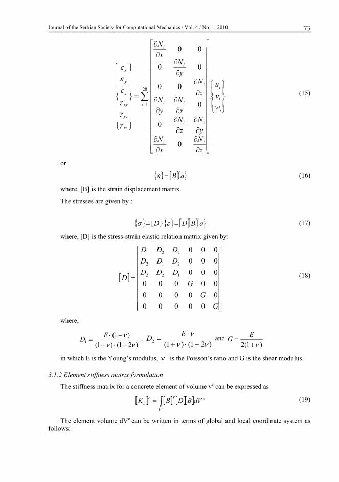
The stresses are given by :
aBDD ][ (17)
where, [D] is the stress-strain elastic relation matrix given by:
G
G
G
DDD
DDD
DDD
D
00000
00000
00000
000
000
000
122
212
221
(18)
where,
)21()1(
)1(1
ED ,
)21()1(2
ED and
)1(2
EG
in which E is the Young’s modulus, is the Poisson’s ratio and G is the shear modulus.
3.1.2 Element stiffness matrix formulation
The stiffness matrix for a concrete element of volume ve can be expressed as
e
V
Teb dVBDBK
e (19)
The element volume dVe can be written in terms of global and local coordinate system as follows:
Adel A. Al- Azzawi and Ali M. Al-Obaidie: Nonlinear Three Dimensional Finite Element Analysis …
74
dddJdxdydzdve (20)
where,
J , is the determinant of Jacobian matrix.
Therefore, equation (19) can be written as:
1
1
1
1
1
1
dddJBDBK Te
b (21)
where, for the natural coordinates, the limits of integration become -1 and +1.
3.2 Reinforcement representation
There are three alternative representations, which have been widely used to simulate the reinforcement in connection with the finite element formulation. These representations are (Scordelis 1971):
a- Discrete representation.
b- Distributed representation.
c-Embedded representation.
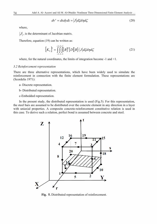
In the present study, the distributed representation is used (Fig.5). For this representation, the steel bars are assumed to be distributed over the concrete element in any direction in a layer with uniaxial properties. A composite concrete-reinforcement constitutive relation is used in this case. To derive such a relation, perfect bond is assumed between concrete and steel.
Fig. 5. Distributed representation of reinforcement.
Journal of the Serbian Society for Computational Mechanics / Vol. 4 / No. 1, 2010
75
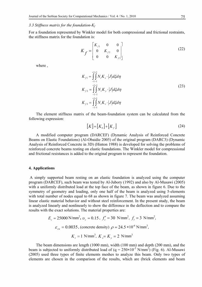
3.3 Stiffness matrix for the foundation-Kf
For a foundation represented by Winkler model for both compressional and frictional restraints, the stiffness matrix for the foundation is:
3
2
1
00
00
00
f
f
f
K
K
K
fK (22)
where ,
1
1
1
1
3
1
1
1
1
2
1
1
1
1
1
ddJKNK
ddJKNK
ddJKNK
zif
yif
xif
(23)
The element stiffness matrix of the beam-foundation system can be calculated from the following expression:
fb KKK (24)
A modified computer program (DARCEF) (Dynamic Analysis of Reinforced Concrete Beams on Elastic Foundations) (Al-Obaidie 2005) of the original program (DARC3) (Dynamic Analysis of Reinforced Concrete in 3D) (Hinton 1988) is developed for solving the problems of reinforced concrete beams resting on elastic foundations. The Winkler model for compressional and frictional resistances is added to the original program to represent the foundation.
4. Applications
A simply supported beam resting on an elastic foundation is analyzed using the computer program (DARCEF), such beam was tested by Al-Jubory (1992) and also by Al-Musawi (2005) with a uniformly distributed load at the top face of the beam, as shown in figure 6. Due to the symmetry of geometry and loading, only one half of the beam is analyzed using 5-elements with total number of nodes equal to 68 as shown in figure 7. The beam was analyzed assuming linear elastic material behavior and without steel reinforcement. In the present study, the beam is analyzed linearly and nonlinearly to show the difference in the deflection and to compare the results with the exact solutions. The material properties are:
25000cE N/mm2, 15.0c , 30cf N/mm2, 3tf N/mm2,
0035.0cu , (concrete density) 5.24 ×10⁻⁶ N/mm3,
1zK N/mm3, 2 yx KK N/mm3
The beam dimensions are length (1000 mm), width (100 mm) and depth (200 mm), and the beam is subjected to uniformly distributed load of (q = 250×10-3 N/mm2) (Fig. 6). Al-Musawi (2005) used three types of finite elements meshes to analyze this beam. Only two types of elements are chosen in the comparison of the results, which are (brick elements and beam
Adel A. Al- Azzawi and Ali M. Al-Obaidie: Nonlinear Three Dimensional Finite Element Analysis …
76
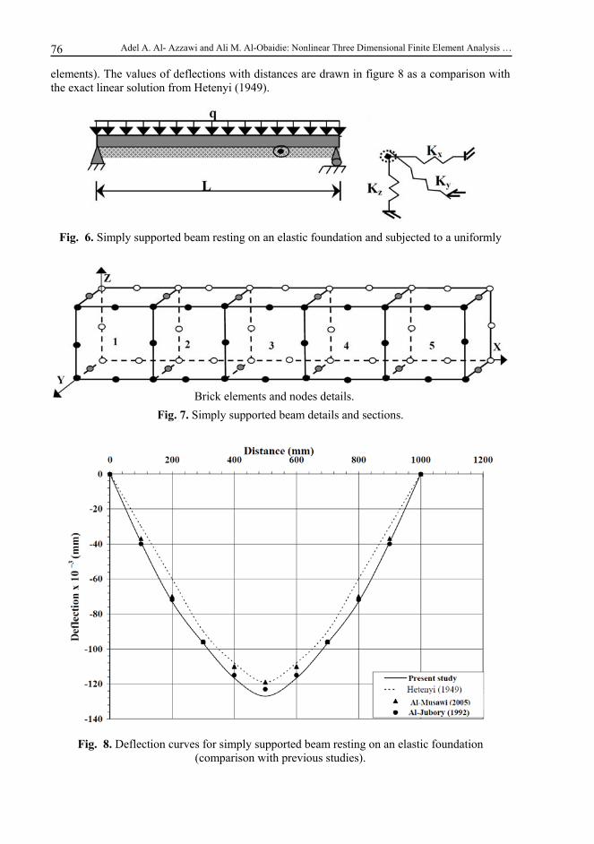
elements). The values of deflections with distances are drawn in figure 8 as a comparison with the exact linear solution from Hetenyi (1949).
Fig. 6. Simply supported beam resting on an elastic foundation and subjected to a uniformly
Fig. 7. Simply supported beam details and sections.
Fig. 8. Deflection curves for simply supported beam resting on an elastic foundation (comparison with previous studies).
Brick elements and nodes details.
Journal of the Serbian Society for Computational Mechanics / Vol. 4 / No. 1, 2010
77
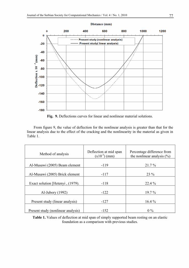
Fig. 9. Deflections curves for linear and nonlinear material solutions.
From figure 9, the value of deflection for the nonlinear analysis is greater than that for the linear analysis due to the effect of the cracking and the nonlinearity in the material as given in Table 1.
Method of analysis Deflection at mid span
(x10-3) (mm) Percentage difference from the nonlinear analysis (%)
Al-Musawi (2005) Beam element -119 21.7 %
Al-Musawi (2005) Brick element -117 23 %
Exact solution [Hetenyi , (1979). -118 22.4 %
Al-Jubory (1992) -122 19.7 %
Present study (linear analysis) -127 16.4 %
Present study (nonlinear analysis) -152 0 %
Table 1. Values of deflection at mid span of simply supported beam resting on an elastic foundation as a comparison with previous studies.
Adel A. Al- Azzawi and Ali M. Al-Obaidie: Nonlinear Three Dimensional Finite Element Analysis …
78
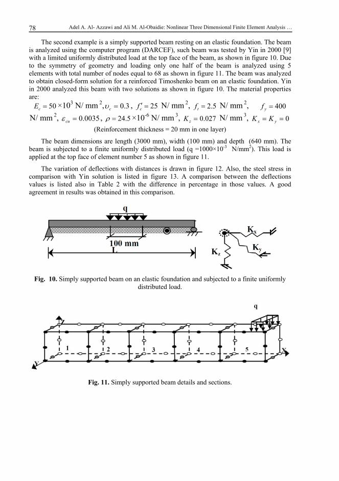
The second example is a simply supported beam resting on an elastic foundation. The beam is analyzed using the computer program (DARCEF), such beam was tested by Yin in 2000 [9] with a limited uniformly distributed load at the top face of the beam, as shown in figure 10. Due to the symmetry of geometry and loading only one half of the beam is analyzed using 5 elements with total number of nodes equal to 68 as shown in figure 11. The beam was analyzed to obtain closed-form solution for a reinforced Timoshenko beam on an elastic foundation. Yin in 2000 analyzed this beam with two solutions as shown in figure 10. The material properties are:
50cE ×103 Ν/ mm 2, 3.0c , 25cf Ν/ mm 2, 5.2tf Ν/ mm 2, 400yf
Ν/ mm 2, 0035.0cu , 5.24 ×10⁻⁶ Ν/ mm 3, 027.0zK Ν/ mm 3, 0 yx KK (Reinforcement thickness = 20 mm in one layer)
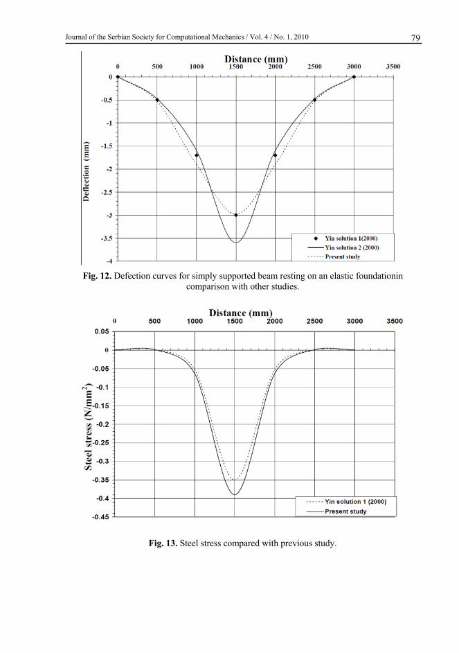
The beam dimensions are length (3000 mm), width (100 mm) and depth (640 mm). The beam is subjected to a finite uniformly distributed load (q =1000×10-3 N/mm2). This load is applied at the top face of element number 5 as shown in figure 11.
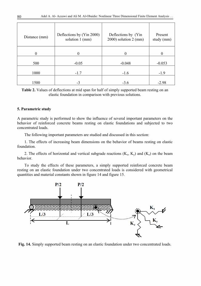
The variation of deflections with distances is drawn in figure 12. Also, the steel stress in comparison with Yin solution is listed in figure 13. A comparison between the deflections values is listed also in Table 2 with the difference in percentage in those values. A good agreement in results was obtained in this comparison.
Fig. 10. Simply supported beam on an elastic foundation and subjected to a finite uniformly distributed load.
Fig. 11. Simply supported beam details and sections.
Journal of the Serbian Society for Computational Mechanics / Vol. 4 / No. 1, 2010
79
Fig. 12. Defection curves for simply supported beam resting on an elastic foundationin comparison with other studies.
Fig. 13. Steel stress compared with previous study.
Adel A. Al- Azzawi and Ali M. Al-Obaidie: Nonlinear Three Dimensional Finite Element Analysis …
80
Distance (mm) Deflections by (Yin 2000)
solution 1 (mm) Deflections by (Yin
2000) solution 2 (mm) Present
study (mm)
0 0 0 0
500 -0.05 -0.048 -0.053
1000 -1.7 -1.6 -1.9
1500 -3 -3.6 -2.98
Table 2. Values of deflections at mid span for half of simply supported beam resting on an elastic foundation in comparison with previous solutions.
5. Parametric study
A parametric study is performed to show the influence of several important parameters on the behavior of reinforced concrete beams resting on elastic foundations and subjected to two concentrated loads.
The following important parameters are studied and discussed in this section:
1. The effects of increasing beam dimensions on the behavior of beams resting on elastic foundation.
2. The effects of horizontal and vertical subgrade reactions (Kx, Ky) and (Kz) on the beam behavior.
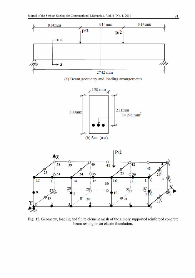
To study the effects of these parameters, a simply supported reinforced concrete beam resting on an elastic foundation under two concentrated loads is considered with geometrical quantities and material constants shown in figure 14 and figure 15.
Fig. 14. Simply supported beam resting on an elastic foundation under two concentrated loads.
Journal of the Serbian Society for Computational Mechanics / Vol. 4 / No. 1, 2010
81
Fig. 15. Geometry, loading and finite element mesh of the simply supported reinforced concrete beam resting on an elastic foundation.

Adel A. Al- Azzawi and Ali M. Al-Obaidie: Nonlinear Three Dimensional Finite Element Analysis …
82
The material properties of the reinforced concrete beam are:
N/mm2, 0.15υc , 36cf N/mm2, 8.3tf N/mm2,
, 200000sE N/mm2, 333yf N/mm2,
1983sA mm2, 5.24 ×10⁻⁶ N/mm3,
Reinforcement thickness t = 3.91 mm) (P/2 = 90 ×103 N)
5.1 Effects of beam dimensions on the behavior
To show the effects of increasing the beam dimensions on the behavior of reinforced concrete beams, different values of dimensions are considered. In the first case the effects of beam width is studied. The same properties of the beam are used except the width of the beam is taken equal to two times and three times of its original value (b = 300 mm and b = 450 mm).
The effect of increasing the beam width on maximum deflection is shown in figure 16. From this figure, the maximum deflection will decrease at a decreasing rate as the beam width is increased. It was found that by increasing the width of the beam from (150 to 450 mm), the maximum deflection for the beam is decreased by (31.25%).
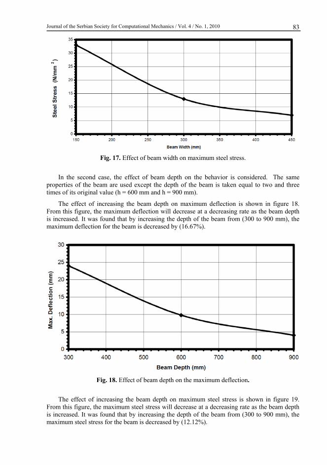
The effect of increasing the beam width on maximum steel stress is shown in figure 17. From this figure, the maximum steel stress will decrease at a decreasing rate as the beam width is increased. It was found that by increasing the width of the beam from (150 to 450 mm), the maximum steel stress for the beam is decreased by (21.21%).
Fig. 16. Effect of beam width on the maximum deflection.
Journal of the Serbian Society for Computational Mechanics / Vol. 4 / No. 1, 2010
83
Fig. 17. Effect of beam width on maximum steel stress.
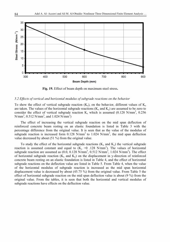
In the second case, the effect of beam depth on the behavior is considered. The same properties of the beam are used except the depth of the beam is taken equal to two and three times of its original value (h = 600 mm and h = 900 mm).
The effect of increasing the beam depth on maximum deflection is shown in figure 18. From this figure, the maximum deflection will decrease at a decreasing rate as the beam depth is increased. It was found that by increasing the depth of the beam from (300 to 900 mm), the maximum deflection for the beam is decreased by (16.67%).
Fig. 18. Effect of beam depth on the maximum deflection.
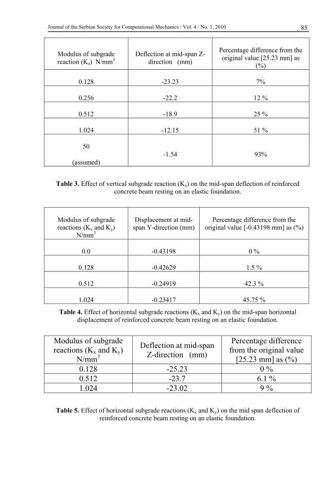
The effect of increasing the beam depth on maximum steel stress is shown in figure 19. From this figure, the maximum steel stress will decrease at a decreasing rate as the beam depth is increased. It was found that by increasing the depth of the beam from (300 to 900 mm), the maximum steel stress for the beam is decreased by (12.12%).
Adel A. Al- Azzawi and Ali M. Al-Obaidie: Nonlinear Three Dimensional Finite Element Analysis …
84
Fig. 19. Effect of beam depth on maximum steel stress.
5.2 Effects of vertical and horizontal modulus of subgrade reactions on the behavior
To show the effect of vertical subgrade reaction (Kz), on the behavior, different values of Kz are taken. The values of the horizontal subgrade reactions (Kx and Ky) are assumed to be zero to consider the effect of vertical subgrade reaction Kz which is assumed (0.128 N/mm3, 0.256 N/mm3, 0.512 N/mm3, and 1.024 N/mm3)
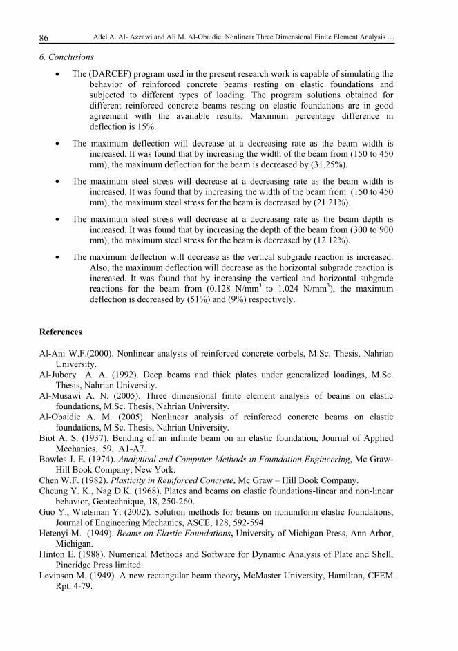
The effect of increasing the vertical subgrade reaction on the mid span deflection of reinforced concrete beam resting on an elastic foundation is listed in Table 3 with the percentage difference from the original value. It is seen that as the value of the modulus of subgrade reaction is increased form 0.128 N/mm3 to 1.024 N/mm3, the mid span deflection value decreased by about (51 %) from the original value.
To study the effect of the horizontal subgrade reactions (Kx and Ky) the vertical subgrade reaction is assumed constant and equal to (Kz =0 .128 N/mm3). The values of horizontal subgrade reaction are assumed as (0.0, 0.128 N/mm3, 0.512 N/mm3, 1.024 N/mm3). The effect of horizontal subgrade reaction (Kx and Ky) on the displacement in y-direction of reinforced concrete beam resting on an elastic foundation is listed in Table 4, and the effect of horizontal subgrade reactions on the deflection value are listed in Table 5. From Table 4, when the value of the horizontal modulus of subgrade reaction is increased as the mid span horizontal displacement value is decreased by about (45.75 %) from the original value. From Table 5 the effect of horizontal subgrade reaction on the mid span deflection value is about (9 %) from the original value. From the tables, it is seen that both the horizontal and vertical modulus of subgrade reactions have effects on the deflection value.
Journal of the Serbian Society for Computational Mechanics / Vol. 4 / No. 1, 2010
85
Modulus of subgrade reaction (Kz) N/mm3
Deflection at mid-span Z-direction (mm)
Percentage difference from the original value [25.23 mm] as
(%)
0.128 -23.23 7%
0.256 -22.2 12 %
0.512 -18.9 25 %
1.024 -12.15 51 %
50
(assumed) -1.54 93%
Table 3. Effect of vertical subgrade reaction (Kz) on the mid-span deflection of reinforced concrete beam resting on an elastic foundation.
Modulus of subgrade reactions (Kx and Ky)
N/mm3
Displacement at mid-span Y-direction (mm)
Percentage difference from the original value [-0.43198 mm] as (%)
0.0 -0.43198 0 %
0.128 -0.42629 1.5 %
0.512 -0.24919 42.3 %
1.024 -0.23417 45.75 %
Table 4. Effect of horizontal subgrade reactions (Kx and Ky) on the mid-span horizontal displacement of reinforced concrete beam resting on an elastic foundation.
Modulus of subgrade reactions (Kx and Ky)
N/mm3
Deflection at mid-span Z-direction (mm)
Percentage difference from the original value
[25.23 mm] as (%) 0.128 -25.23 0 % 0.512 -23.7 6.1 % 1.024 -23.02 9 %
Table 5. Effect of horizontal subgrade reactions (Kx and Ky) on the mid span deflection of reinforced concrete beam resting on an elastic foundation.
Adel A. Al- Azzawi and Ali M. Al-Obaidie: Nonlinear Three Dimensional Finite Element Analysis …
86
6. Conclusions
The (DARCEF) program used in the present research work is capable of simulating the behavior of reinforced concrete beams resting on elastic foundations and subjected to different types of loading. The program solutions obtained for different reinforced concrete beams resting on elastic foundations are in good agreement with the available results. Maximum percentage difference in deflection is 15%.
The maximum deflection will decrease at a decreasing rate as the beam width is increased. It was found that by increasing the width of the beam from (150 to 450 mm), the maximum deflection for the beam is decreased by (31.25%).
The maximum steel stress will decrease at a decreasing rate as the beam width is increased. It was found that by increasing the width of the beam from (150 to 450 mm), the maximum steel stress for the beam is decreased by (21.21%).
The maximum steel stress will decrease at a decreasing rate as the beam depth is increased. It was found that by increasing the depth of the beam from (300 to 900 mm), the maximum steel stress for the beam is decreased by (12.12%).
The maximum deflection will decrease as the vertical subgrade reaction is increased. Also, the maximum deflection will decrease as the horizontal subgrade reaction is increased. It was found that by increasing the vertical and horizontal subgrade reactions for the beam from (0.128 N/mm3 to 1.024 N/mm3), the maximum deflection is decreased by (51%) and (9%) respectively.
References
Al-Ani W.F.(2000). Nonlinear analysis of reinforced concrete corbels, M.Sc. Thesis, Nahrian University.
Al-Jubory A. A. (1992). Deep beams and thick plates under generalized loadings, M.Sc. Thesis, Nahrian University.
Al-Musawi A. N. (2005). Three dimensional finite element analysis of beams on elastic foundations, M.Sc. Thesis, Nahrian University.
Al-Obaidie A. M. (2005). Nonlinear analysis of reinforced concrete beams on elastic foundations, M.Sc. Thesis, Nahrian University.
Biot A. S. (1937). Bending of an infinite beam on an elastic foundation, Journal of Applied Mechanics, 59, A1-A7.
Bowles J. E. (1974). Analytical and Computer Methods in Foundation Engineering, Mc Graw-Hill Book Company, New York.
Chen W.F. (1982). Plasticity in Reinforced Concrete, Mc Graw – Hill Book Company. Cheung Y. K., Nag D.K. (1968). Plates and beams on elastic foundations-linear and non-linear
behavior, Geotechnique, 18, 250-260. Guo Y., Wietsman Y. (2002). Solution methods for beams on nonuniform elastic foundations,
Journal of Engineering Mechanics, ASCE, 128, 592-594. Hetenyi M. (1949). Beams on Elastic Foundations, University of Michigan Press, Ann Arbor,
Michigan. Hinton E. (1988). Numerical Methods and Software for Dynamic Analysis of Plate and Shell,
Pineridge Press limited. Levinson M. (1949). A new rectangular beam theory, McMaster University, Hamilton, CEEM
Rpt. 4-79.

Journal of the Serbian Society for Computational Mechanics / Vol. 4 / No. 1, 2010
87
Scordelis A. C (1971). Finite element analysis of reinforced concrete slabs, Structural Engineering Research Report, No. 38, Dept. of Civil Eng. university of Albert, Edmonton, Canada.
Selvadurai A. P. S (1979). Elastic Analysis of Soil Foundation Interaction, Elsevier Scientific Publishing Company.
Terzaghi K. (1955). Evaluation of coefficient of subgrade reaction, Geotechnique, 5, 197-326. Winkler E.(1867). Die lehre von elasticitat und festigkeit, (H. Dominic us), Prague, 182-184. Yankelevsky D. Z. , Adian M. A., Eisenberger M. (1988). Beams on nonlinear Winkler
foundations with gaps, Computers and Geotechnique, 6, 1-11. Yin J. (2000). Closed – form solution for reinforced Timoshenko beam on elastic foundation,
Journal of Engineering Mechanics, American Society of Civil Engineers, 128, 868-874.