Embed Size (px)
Citation preview

25
NONMECHANICAL CONTROL OF SOLIDS
FLOW IN SINGLE AND MULTI-LOOP SYSTEMS
T. M. Knowlton
Particulate Solid Research, Inc. Chicago, IL USA
Keywords: L-valve, multi-loop systems, solids circulation, solids flow control
Abstract – In most gas solids processes involving substantial solids circulation around one or two loops, the circulation rate around the loop is controlled by a valve – typically a slide valve. However, many new process such as chemical looping processes, operate at higher pressures and pressures than the previous processes, and solids flow control using a slide valve is either to expensive or not possible. This is because slide valve technology does not presently extend to the high temperatures and pressures used in many of the new processes.
Therefore, developers are turning to nonmechanical means to control the solids flow around the solids flow loops. This paper describes the principles involved in nonmechanical control of solids around a loop, and the advantages and disadvantages of the various types of nonmechanical solids flow control systems.
INTRODUCTION Many gas solids processes involve single or multiple-loop circulation systems. Most of the
existing circulation processes have temperatures equal to or less than about 760C (1400F) and pressures of about 2 bar(g) or lower. This allows the use of mechanical slide vales to control the solids flow rate in these systems.
Newer process such as chemical looping processes require temperatures up to 982C (1800F) and pressures up to 35 bar(g)(500 psig). Using slide valves to control these processes would involve exceptionally expensive valves being used at temperatures and pressures where almost no reliable data exist on their operation. Therefore, many of the processes are using nonmechanical means to control the solids flow rate in these systems.
An evaluation of the different types of circulation systems being used is given below. Often, there is a lack of understanding of how these nonmechanical systems operate. Therefore, the basic principles of nonmechanical systems will be discussed before the evaluation.
NONMECHANICAL SOLIDS FLOW DEVICES
A nonmechanical solids flow device is one which uses only aeration gas in conjunction with its geometrical shape to cause solids to flow through it. Nonmechanical solids flow control devices have several advantages over mechanical solids flow devices:
1) They have no moving mechanical parts which are subject to wear and/or seizure. This
feature is especially beneficial when operating at elevated temperatures and pressures. 2) They are inexpensive because they are constructed of ordinary pipe and fittings. 3) They can be fabricated “in-house” which avoids long delivery times, often associated
with the purchase or replacement of large mechanical valves.
Nonmechanical solids flow devices are of two different types:
1) Solids Flow Control Devices (Valves) – An example of this type of device is the
L-valve.

26
2) Solids Flow-Through Devices which DO NOT CONTROL solids flow. They automatically pass solids through them. Examples of these devices are the loop seal and the “automatic” L-valve
There is often confusion as to how these modes differ, and what kind of nonmechanical
devices should be used for a particular application. Each mode of operation is discussed below.
Nonmechanical Valve Mode Operation In the valve mode of operation, the solids flow rate through the nonmechanical device is
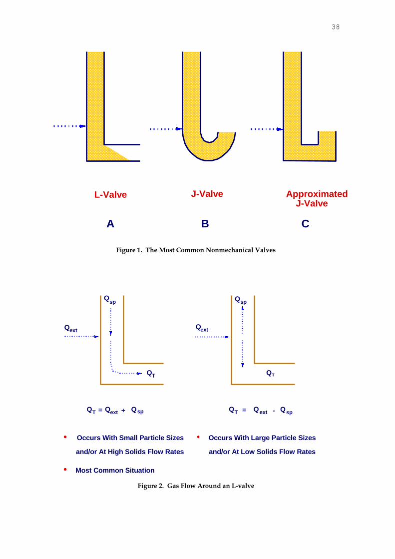
controlled by the amount of aeration gas added to it. The most common types of nonmechanical valves are the L-valve and the J-valve. These devices are shown schematically in Figure 1. The primary differences between these devices are their shape and the direction in which they discharge solids. Both devices operate on the same principle. It is harder to fabricate a smooth 180-degree bend for a typical J-valve. Therefore, the J-valve can be approximated and configured more simply by the geometry shown in Figure 1C.
The most common nonmechanical valve is the L-valve (so named because it is shaped like the letter “L”) because it is easiest to construct, and also because it is slightly more efficient than the J-valve (Knowlton et al, 1978). Because the principle of operation of non-mechanical valves is the same, how nonmechanical valves operate is presented through a discussion of the L-valve.
Solids flow through a nonmechanical valve because of drag forces on the particles produced by the aeration gas. When aeration gas is added to a nonmechanical valve, gas flows downward through the particles and around the constricting bend. This relative gas-solids flow produces a frictional drag force on the particles in the direction of flow. When this drag force exceeds the force required to overcome the resistance to solids flow around the bend, the solids flow through the valve.
The gas flow rate that causes the solids to flow around an L-valve is not the amount of aeration gas added to the valve. If gas is traveling down the moving packed-bed standpipe with the solids (which is the most common occurrence) , the amount of gas which flows around the L-valve bend, QT, is the sum of the standpipe gas flow, Qsp, plus the aeration gas flow, QA, as shown in Figure 2A. If the gas is flowing up the standpipe (which would be the case when the standpipe is operating with low solids flow rates and/or large solids), then the amount of gas flowing around the bed, QT, is the difference between the aeration gas flow and the gas flowing up the standpipe as shown in Figure 2B.
When aeration is added to a nonmechanical valve, solids do not begin to flow immediately. The initial aeration gas is not enough to produce the frictional force required to start solids flow. Above the threshold amount of gas required to initiate solids flow, adding aeration gas to the valve causes the solids flow rate to increase, and reducing the amount of aeration to the valve causes the solids flow rate to decrease. In general, there is little hysteresis in the aeration-vs-solids flow rate curve for a nonmechanical valve.
Nonmechanical valves work best with materials having average particle sizes between 100 to 5000 microns. These materials are in Geldart Groups B and D. Materials with average particle sizes greater than about 3000 microns require substantial amounts of gas to generate the drag forces required to make the solids flow around the constricting bend. This is because larger solids have less surface area available for the generation of the drag forces required to produce flow through a nonmechanical valve. These larger materials work best in nonmechanical valves if there are smaller particles mixed in with them to decrease the voidage of the solids mixture, increasing the drag on the solids when aeration is added and causing the solids to flow more easily through the constricting bend.
In general, Geldart Group A materials (with average particles sizes from approximately 30 to 100 microns) do not work well in L-valves. Group A materials retain air in their interstices and remain fluidized for a substantial period of time when they are added to the standpipe attached to the nonmechanical valve. Because they remain fluidized, they flow through the constricting bend like a liquid, and the L-valve cannot control the solids. Although most Group A materials cannot be used with nonmechanical devices operating in the control mode, materials at the upper end of the Group A classification which contain few fines (particles smaller than 44 microns) can and have been controlled in nonmechanical valves.

27
Geldart Group C materials (with average particle sizes less than about 30 microns) have are very cohesive (flour is a typical example). These materials do not flow well through any type of pipe, and do not flow well in L-valves.
A nonmechanical device operating in the valve control mode is always located at the bottom of an underflow standpipe operating in moving packed-bed flow. Nonmechanical valves used for control will not work with any other type of standpipe. The standpipe is usually fed by a hopper, which can either be fluidized on non-fluidized. Knowlton and Hirsan (1978) and Knowlton, Hirsan, and Leung (1978) have shown that the operation of a nonmechanical valve is dependent upon the pressure balance and the geometry of the system. In fact, understanding the operation of nonmechanical valves used for solids flow control depends on two things – the pressure balance around the system, and understanding non-fluidized underflow standpipe operation.
Underflow Non-fluidized Standpipe Operation
A standpipe is a length of pipe through which solids flow by gravity. Standpipes can be
vertical, angled, or a mixture of angled and vertical pipes called a hybrid standpipe. The standpipe was invented by a research group working at the Jersey Standard Company in the 1940’s (Campbell et. al., 1948) trying to develop an FCC unit to produce high-octane aviation gasoline in World War II.
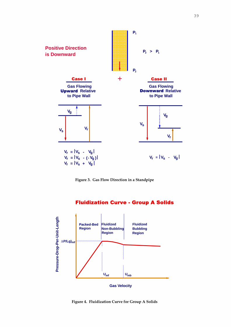
The purpose of a standpipe is to transfer solids from a region of lower pressure to a region of higher pressure. Solids can be transferred by gravity from a low pressure to a higher pressure if gas flows upward relative to the downward flowing solids. This relative gas-solids flow will then generate the sealing pressure drop required for the system. The direction of the actual gas flow in the standpipe relative to the standpipe wall can be either up or down and still have the relative gas-solids velocity, vr, directed upwards. This is sometimes difficult to understand, but it can be explained with the aid of Figure 3, and the definition of the relative velocity. The relative gas-solids velocity, vr, is defined as:
v v vr s g (1)
where vs is the solids velocity, and is the interstitial gas velocity (vg = U/). It is generally easier to visualize what is occurring in a solids transfer system by mentally
traveling along with the solids. Therefore, the positive reference direction for determining vr will be the direction that the solids are flowing. For standpipe flow, this direction is downward.
In Figure 3 solids are being transferred downward in a standpipe from pressure P1 to a higher pressure P2. Solids velocities in Figure 3 are denoted by the length of the bold arrows, gas velocities by the length of the dashed arrows, and the relative gas-solids velocity by the length of the thin-lined arrows.
For Case 1 in Figure 3, solids are flowing downward, and gas is flowing upward relative to the standpipe wall. The relative velocity is directed upward, and is equal to the sum of the solids velocity and the gas velocity, i. e.:
v v v v vr s g s g (2)
For Case 2, solids are flowing down the standpipe relative to the standpipe wall. Gas is also
flowing down the standpipe relative to the standpipe wall, but at a velocity less than that of the solids. For this case, the relative velocity is also directed upward, and is equal to the difference between the solids velocity and the gas velocity, i. e.:
v v vr s g (3)
In both cases, if one were riding down the standpipe with the solids, the gas would appear to
be moving upward relative to your reference point. The gas flowing upward relative to the solids generates a frictional pressure drop. The
relationship between the pressure-drop-per-unit-length (P/Lg) and the relative velocity for a particular material is determined by the fluidization curve for that material. This normal
28
fluidization curve is generated in a fluidization column where the solids are not flowing. However, the relationship also applies for solids flowing in a standpipe.
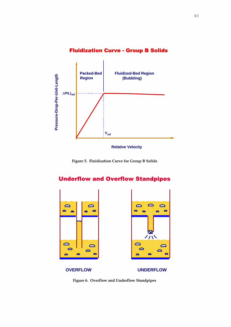
Most standpipe transfer systems use either Geldart Group A or Geldart Group B solids. The fluidization curve for Geldart Group B solids differs from that for Group A solids. For both
types of solids, as the relative gas velocity through the bed increases from zero, the P/(Lg) through the bed increases linearly with vr. This region is called the packed-bed region. At some
vr, the P generated by the gas flowing through the solids is equal to the weight of the solids per unit area and the solids become fluidized. The relative velocity at this point is termed the
interstitial minimum fluidization velocity, vmf, or Umf/mf. The P/(Lg) at vmf is designated as
P/Lg)mf and is often referred to as the fluidized bed “density” at minimum fluidization,
because P/(Lg) has the units of density.
Increases in vr above vmf do not lead to further increases in P/Lg. For Geldart Group B materials, nearly all of any gas flow in excess of that required at vmf goes into the formation of
bubbles. Therefore, as vr increases beyond vmf, P/Lg remains almost constant, and then begins to decrease as the bubble volume in the bed increases.
For Geldart Group A materials, as vr is increased above vmf the solids expand without bubble
generation over a certain velocity range. Because of this bubbleless expansion, P/L decreases over this velocity range. The velocity where bubbles begin to form in Group A materials is called the minimum bubbling velocity, vmb. Typical fluidization curves for Geldart Group A and Geldart Group B materials are shown in Figures 4 and 5, respectively.
There are two basic types of standpipe configurations - the overflow standpipe (Figure 6A) and the underflow standpipe (Figure 6B). The overflow standpipe is so named because the solids “overflow” from the top of the fluidized bed into the standpipe, and there is no bed of solids above the standpipe. In the underflow standpipe, the solids are introduced into the standpipe from the underside, or bottom, of the bed or hopper, and a bed of solids is present above the standpipe.
Standpipes generally operate in either packed-bed flow or fluidized-bed flow. 1. Packed-Bed Flow In packed-bed flow vr is less than vmf, and the voidage in the
standpipe is more or less constant. As vr is increased, P/L increases more or less linearly in packed-bed flow.
2. Fluidized-Bed Flow In fluidized-bed flow, vr is equal to or greater than vmf. The voidage in the standpipe can (and generally does) change along the length of the standpipe, and
P/Lg does not change significantly with increasing vr. In any gas-solids flow system, a pressure-drop loop can be defined such that the sum of the
pressure drop components around the loop is zero. In many (but not all) pressure-drop loops, the standpipe is the dependent part of the loop. This means that the pressure drop across the standpipe will automatically adjust to balance the pressure drop produced by the other independent components (which do not automatically adjust their pressure drops) in the loop. How the standpipe pressure drop adjustment is made is different for overflow and underflow standpipes.
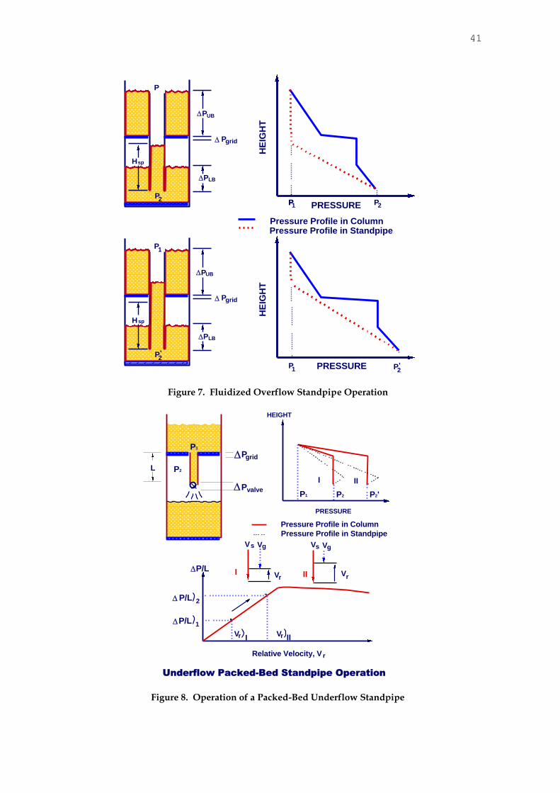
Many standpipes are fluidized overflow standpipes. Operation of this type of standpipe is easy to understand, and non-control nonmechanical devices (loop seal, automatic L-valve, etc.) operate with this type of standpipe above them.
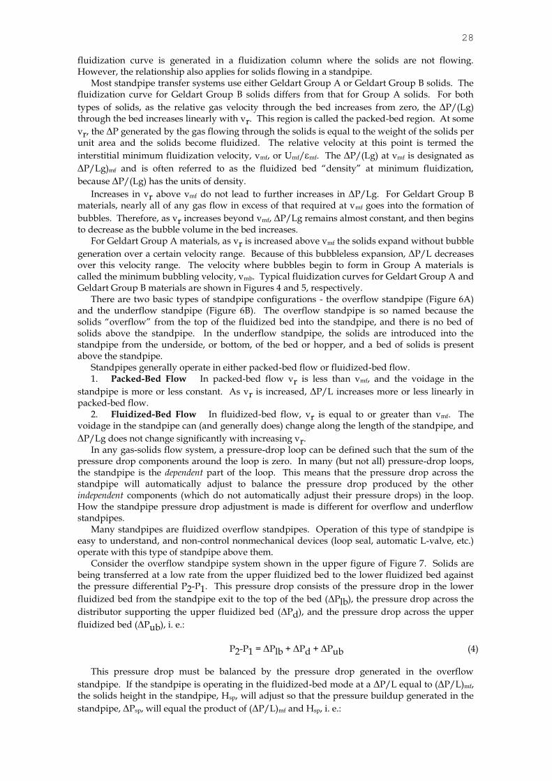
Consider the overflow standpipe system shown in the upper figure of Figure 7. Solids are being transferred at a low rate from the upper fluidized bed to the lower fluidized bed against the pressure differential P2-P1. This pressure drop consists of the pressure drop in the lower
fluidized bed from the standpipe exit to the top of the bed (Plb), the pressure drop across the
distributor supporting the upper fluidized bed (Pd), and the pressure drop across the upper
fluidized bed (Pub), i. e.:
P2-P1 = Plb + Pd + Pub (4) This pressure drop must be balanced by the pressure drop generated in the overflow
standpipe. If the standpipe is operating in the fluidized-bed mode at a P/L equal to (P/L)mf, the solids height in the standpipe, Hsp, will adjust so that the pressure buildup generated in the
standpipe, Psp, will equal the product of (P/L)mf and Hsp, i. e.:
29
Psp = P2-P1 = Plb + Pd + Pub = (P/L)mf (Hsp) (5)
If the gas flow rate through the two beds is increased, Pd increases while the pressure drops across the two fluidized beds essentially remain constant. Therefore, P2-P1 increases to P'2-P1. The pressure drop across the overflow standpipe will also increase to P'2-P1. The standpipe pressure drop increases because the height of fluidized solids in the standpipe increases from Hsp to H'sp, i. e.:
Psp = P'2-P1 = (P/L)mf (H'sp) (6)
This is shown schematically in the lower figure of Figure 7, and the change is also reflected in
the pressure diagram. If the increase in the pressure drop across the distributor is so much that Hsp must increase to a value greater than the standpipe height available to seal the pressure differential, the standpipe will not operate.
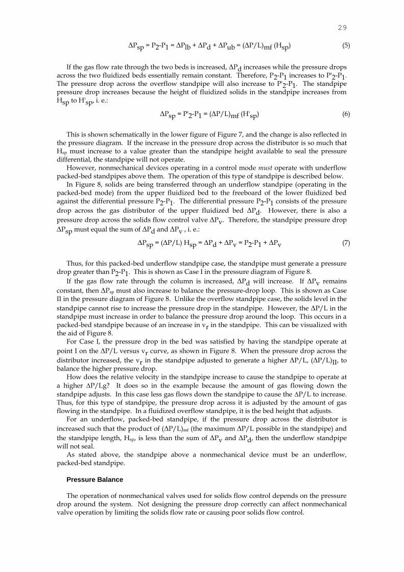
However, nonmechanical devices operating in a control mode must operate with underflow packed-bed standpipes above them. The operation of this type of standpipe is described below.
In Figure 8, solids are being transferred through an underflow standpipe (operating in the packed-bed mode) from the upper fluidized bed to the freeboard of the lower fluidized bed against the differential pressure P2-P1. The differential pressure P2-P1 consists of the pressure
drop across the gas distributor of the upper fluidized bed Pd. However, there is also a
pressure drop across the solids flow control valve Pv. Therefore, the standpipe pressure drop
Psp must equal the sum of Pd and Pv , i. e.:
Psp = (P/L) Hsp = Pd + Pv = P2-P1 + Pv (7)
Thus, for this packed-bed underflow standpipe case, the standpipe must generate a pressure
drop greater than P2-P1. This is shown as Case I in the pressure diagram of Figure 8.
If the gas flow rate through the column is increased, Pd will increase. If Pv remains
constant, then Psp must also increase to balance the pressure-drop loop. This is shown as Case II in the pressure diagram of Figure 8. Unlike the overflow standpipe case, the solids level in the
standpipe cannot rise to increase the pressure drop in the standpipe. However, the P/L in the standpipe must increase in order to balance the pressure drop around the loop. This occurs in a packed-bed standpipe because of an increase in vr in the standpipe. This can be visualized with the aid of Figure 8.
For Case I, the pressure drop in the bed was satisfied by having the standpipe operate at
point I on the P/L versus vr curve, as shown in Figure 8. When the pressure drop across the
distributor increased, the vr in the standpipe adjusted to generate a higher P/L, (P/L)II, to balance the higher pressure drop.
How does the relative velocity in the standpipe increase to cause the standpipe to operate at
a higher P/Lg? It does so in the example because the amount of gas flowing down the
standpipe adjusts. In this case less gas flows down the standpipe to cause the P/L to increase. Thus, for this type of standpipe, the pressure drop across it is adjusted by the amount of gas flowing in the standpipe. In a fluidized overflow standpipe, it is the bed height that adjusts.
For an underflow, packed-bed standpipe, if the pressure drop across the distributor is
increased such that the product of (P/L)mf (the maximum P/L possible in the standpipe) and
the standpipe length, Hsp, is less than the sum of Pv and Pd, then the underflow standpipe will not seal.
As stated above, the standpipe above a nonmechanical device must be an underflow, packed-bed standpipe.
Pressure Balance
The operation of nonmechanical valves used for solids flow control depends on the pressure drop around the system. Not designing the pressure drop correctly can affect nonmechanical valve operation by limiting the solids flow rate or causing poor solids flow control.
30
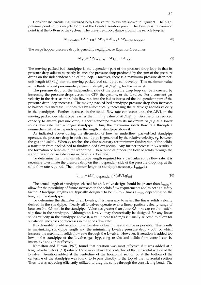
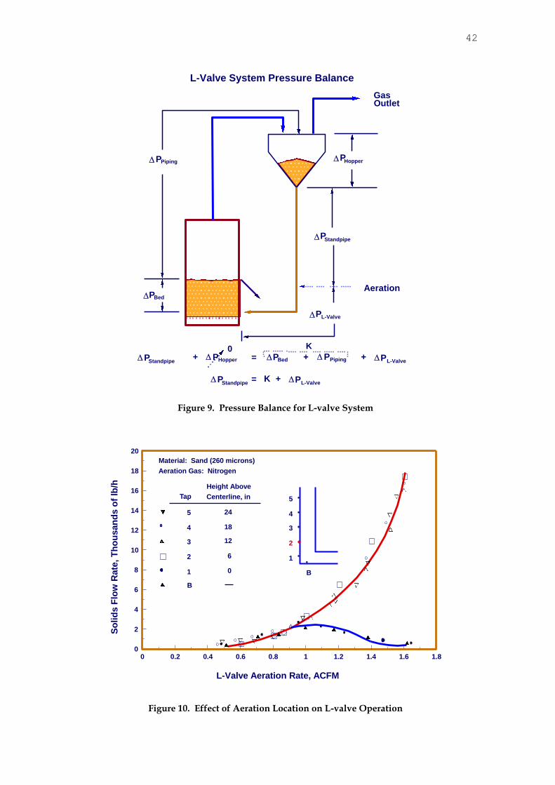
Consider the circulating fluidized bed/L-valve return system shown in Figure 9. The high-pressure point in this recycle loop is at the L-valve aeration point. The low-pressure common point is at the bottom of the cyclone. The pressure-drop balance around the recycle loop is:
PL-valve + PCFB + Pcy = Psp + Psurge hopper (8)
The surge hopper pressure drop is generally negligible, so Equation 1 becomes:
Psp PL-valve + PCFB + Pcy (9)
The moving packed-bed standpipe is the dependent part of the pressure-drop loop in that its pressure drop adjusts to exactly balance the pressure drop produced by the sum of the pressure drops on the independent side of the loop. However, there is a maximum pressure-drop-per-
unit-length (P/Lg) that the moving packed-bed standpipe can develop. This maximum value
is the fluidized-bed pressure-drop-per-unit-length, P/Lg)mf, for the material. The pressure drop on the independent side of the pressure drop loop can be increased by
increasing the pressure drops across the CFB, the cyclone, or the L-valve. For a constant gas velocity in the riser, as the solids flow rate into the bed is increased the independent part of the pressure drop loop increases. The moving packed-bed standpipe pressure drop then increases to balance this increase. It does this by automatically increasing the relative gas-solids velocity
in the standpipe. Further increases in the solids flow rate can occur until the P/L in the
moving packed-bed standpipe reaches the limiting value of P/Lg)mf. Because of its reduced
capacity to absorb pressure drop, a short standpipe reaches its maximum P/Lg at a lower solids flow rate than a longer standpipe. Thus, the maximum solids flow rate through a nonmechanical valve depends upon the length of standpipe above it.
As indicated above during the discussion of how an underflow, packed-bed standpipe operates, the pressure drop in such a standpipe is generated by the relative velocity, vr, between the gas and solids. When vr reaches the value necessary for minimum fluidization of the solids, a transition from packed-bed to fluidized-bed flow occurs. Any further increase in vr results in the formation of bubbles in the standpipe. These bubbles hinder the flow of solids through the standpipe and cause a decrease in the solids flow rate.
To determine the minimum standpipe length required for a particular solids flow rate, it is necessary to estimate the pressure drop on the independent side of the pressure drop loop at the solid flow rate required. The minimum length of standpipe necessary, Lmin, is:
Lmin = (Pindependent)/(P/Lg)mf (10) The actual length of standpipe selected for an L-valve design should be greater than Lmin to
allow for the possibility of future increases in the solids flow requirements and to act as a safety factor. Standpipe lengths are typically designed to be 1.2 to 2 times Lmin, depending on the length of the standpipe.
To determine the diameter of an L-valve, it is necessary to select the linear solids velocity desired in the standpipe. Nearly all L-valves operate over a linear particle velocity range of between 0 to 0.3 m/s in the standpipe. Velocities greater than about 0.3 m/s can result in stick-slip flow in the standpipe. Although an L-valve may theoretically be designed for any linear solids velocity in the standpipe above it, a value near 0.15 m/s is usually selected to allow for substantial increases or decreases in the solids flow rate.
It is desirable to add aeration to an L-valve as low in the standpipe as possible. This results in maximizing standpipe length and the minimizing L-valve pressure drop - both of which increase the maximum solids flow rate through the L-valve. However, if aeration is added too low in the standpipe of the L-valve, gas bypassing results and solids flow control can be insensitive and/or ineffective.
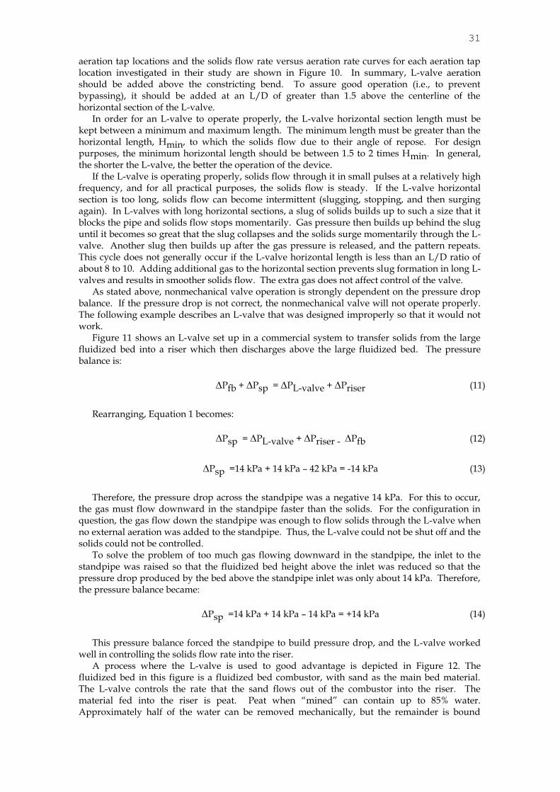
Knowlton and Hirsan (1978) found that aeration was most effective if it was added at a length-to-diameter (L/D) ratio of 1.5 or more above the centerline of the horizontal section of the L-valve. Aeration added at the centerline of the horizontal section or at the bottom of the centerline of the standpipe was found to bypass directly to the top of the horizontal section. Thus, it was not being efficiently utilized to drag the solids through the constricting bend. The
31
aeration tap locations and the solids flow rate versus aeration rate curves for each aeration tap location investigated in their study are shown in Figure 10. In summary, L-valve aeration should be added above the constricting bend. To assure good operation (i.e., to prevent bypassing), it should be added at an L/D of greater than 1.5 above the centerline of the horizontal section of the L-valve.
In order for an L-valve to operate properly, the L-valve horizontal section length must be kept between a minimum and maximum length. The minimum length must be greater than the horizontal length, Hmin, to which the solids flow due to their angle of repose. For design purposes, the minimum horizontal length should be between 1.5 to 2 times Hmin. In general, the shorter the L-valve, the better the operation of the device.
If the L-valve is operating properly, solids flow through it in small pulses at a relatively high frequency, and for all practical purposes, the solids flow is steady. If the L-valve horizontal section is too long, solids flow can become intermittent (slugging, stopping, and then surging again). In L-valves with long horizontal sections, a slug of solids builds up to such a size that it blocks the pipe and solids flow stops momentarily. Gas pressure then builds up behind the slug until it becomes so great that the slug collapses and the solids surge momentarily through the L-valve. Another slug then builds up after the gas pressure is released, and the pattern repeats. This cycle does not generally occur if the L-valve horizontal length is less than an L/D ratio of about 8 to 10. Adding additional gas to the horizontal section prevents slug formation in long L-valves and results in smoother solids flow. The extra gas does not affect control of the valve.
As stated above, nonmechanical valve operation is strongly dependent on the pressure drop balance. If the pressure drop is not correct, the nonmechanical valve will not operate properly. The following example describes an L-valve that was designed improperly so that it would not work.
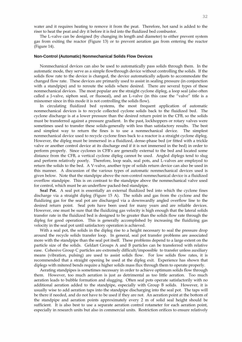
Figure 11 shows an L-valve set up in a commercial system to transfer solids from the large fluidized bed into a riser which then discharges above the large fluidized bed. The pressure balance is:
Pfb + Psp = PL-valve + Priser (11)
Rearranging, Equation 1 becomes:
Psp = PL-valve + Priser - Pfb (12)
Psp =14 kPa + 14 kPa – 42 kPa = -14 kPa (13)
Therefore, the pressure drop across the standpipe was a negative 14 kPa. For this to occur,
the gas must flow downward in the standpipe faster than the solids. For the configuration in question, the gas flow down the standpipe was enough to flow solids through the L-valve when no external aeration was added to the standpipe. Thus, the L-valve could not be shut off and the solids could not be controlled.
To solve the problem of too much gas flowing downward in the standpipe, the inlet to the standpipe was raised so that the fluidized bed height above the inlet was reduced so that the pressure drop produced by the bed above the standpipe inlet was only about 14 kPa. Therefore, the pressure balance became:
Psp =14 kPa + 14 kPa – 14 kPa = +14 kPa (14)
This pressure balance forced the standpipe to build pressure drop, and the L-valve worked
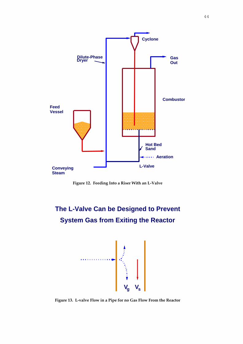
well in controlling the solids flow rate into the riser. A process where the L-valve is used to good advantage is depicted in Figure 12. The
fluidized bed in this figure is a fluidized bed combustor, with sand as the main bed material. The L-valve controls the rate that the sand flows out of the combustor into the riser. The material fed into the riser is peat. Peat when “mined” can contain up to 85% water. Approximately half of the water can be removed mechanically, but the remainder is bound
32
water and it requires heating to remove it from the peat. Therefore, hot sand is added to the riser to heat the peat and dry it before it is fed into the fluidized bed combustor.
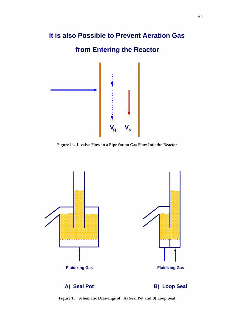
The L-valve can be designed (by changing its length and diameter) to either prevent system gas from exiting the reactor (Figure 13) or to prevent aeration gas from entering the reactor (Figure 14).
Non-Control (Automatic) Nonmechanical Solids Flow Devices
Nonmechanical devices can also be used to automatically pass solids through them. In the
automatic mode, they serve as a simple flowthrough device without controlling the solids. If the solids flow rate to the device is changed, the device automatically adjusts to accommodate the changed flow rate. These devices are primarily used to assist in sealing pressure (in conjunction with a standpipe) and to reroute the solids where desired. There are several types of these nonmechanical devices. The most popular are the straight cyclone dipleg, a loop seal (also often called a J-valve, siphon seal, or fluoseal), and an L-valve (in this case the “valve” title is a misnomer since in this mode it is not controlling the solids flow).
In circulating fluidized bed systems, the most frequent application of automatic nonmechanical devices is to recycle collected cyclone solids back to the fluidized bed. The cyclone discharge is at a lower pressure than the desired return point in the CFB, so the solids must be transferred against a pressure gradient. In the past, lockhoppers or rotary valves were sometimes used to transfer these solids-generally with less than satisfactory results. The best and simplest way to return the fines is to use a nonmechanical device. The simplest nonmechanical device used to recycle cyclone fines back to a reactor is a straight cyclone dipleg. However, the dipleg must be immersed in a fluidized, dense-phase bed (or fitted with a trickle valve or another control device at its discharge end if it is not immersed in the bed) in order to perform properly. Since cyclones in CFB’s are generally external to the bed and located some distance from the CFB, a vertical cyclone dipleg cannot be used. Angled diplegs tend to slug and perform relatively poorly. Therefore, loop seals, seal pots, and L-valves are employed to return the solids to the bed. A V-valve, another type of solids return device can also be used in this manner. A discussion of the various types of automatic nonmechanical devices used is given below. Note that the standpipe above the non-control nonmechanical device is a fluidized overflow standpipe. This is on contrast to the standpipe above the nonmechanical valve used for control, which must be an underflow packed-bed standpipe.
Seal Pot. A seal pot is essentially an external fluidized bed into which the cyclone fines discharge via a straight dipleg (Figure 15 A). The solids and gas from the cyclone and the fluidizing gas for the seal pot are discharged via a downwardly angled overflow line to the desired return point. Seal pots have been used for many years and are reliable devices. However, one must be sure that the fluidizing gas velocity is high enough that the lateral solids transfer rate in the fluidized bed is designed to be greater than the solids flow rate through the dipleg for good operation. This is generally accomplished by increasing the fluidizing gas velocity in the seal pot until satisfactory operation is achieved.
With a seal pot, the solids in the dipleg rise to a height necessary to seal the pressure drop around the recycle solids transfer loop. In general, seal pot transfer problems are associated more with the standpipe than the seal pot itself. These problems depend to a large extent on the particle size of the solids. Geldart Groups A and B particles can be transferred with relative ease. Cohesive Group C particles are extremely difficult/impossible to transfer unless auxiliary means (vibration, pulsing) are used to assist solids flow. For low solids flow rates, it is recommended that a straight opening be used at the dipleg exit. Experience has shown that diplegs with mitered bends require a higher solids mass flux through them to operate properly.
Aerating standpipes is sometimes necessary in order to achieve optimum solids flow through them. However, too much aeration is just as detrimental as too little aeration. Too much aeration leads to bubble formation and slugging. Often seal pots operate satisfactorily with no additional aeration added to the standpipe, especially with Group B solids. However, it is usually wise to add aeration taps into the standpipe discharging into the seal pot. The taps will be there if needed, and do not have to be used if they are not. An aeration point at the bottom of the standpipe and aeration points approximately every 2 m of solid seal height should be sufficient. It is also best to use a separate aeration control rotameter for each aeration point, especially in research units but also in commercial units. Restriction orifices to ensure relatively
33
equal flows to each aeration location can be used, but individual aeration rotameters to each tap are preferred.
Loop Seal. The loop seal (Figure 15B) is essentially a variation of the seal pot. Like the seal
pot, it is composed of a standpipe and a fluidized-bed (upflow) section. However, the solids from the standpipe enter the upflow fluidized bed from the side. This allows the fluidized bed portion of the device to be smaller in diameter, resulting in a smaller transfer device, lower fluidization gas requirements, and a more efficient operation.
The height of the vertical flow portion of the loop seal can be increased to “insulate” the operation of the loop seal from the pressure fluctuations in the bed to which it is discharging. Increasing the height of the vertical portion of the loop seal also helps prevent blowing the seal leg of the loop seal if a pressure upset occurs. However, an extremely large pressure upset will still blow the seal and cause other operational problems as well.
It is essential to fluidize the upflow section of the loop seal in order for solids to flow smoothly through the loop seal. For Geldart Group A solids, little fluidization gas may be required to be added to the upflow section, because they may not defluidize when flowing around the bed. With both types of solids, the minimum amount of aeration gas necessary to produce smooth, steady flow is what should be used. Too much gas results in slugging and unsteady flow. It is also recommended that aeration at the base of the loop seal be separated so that the amount of aeration added below the bottom of the dipleg and the amount added for the upflow section can be varied independently of each other.
Wirth (1995) found that using a cyclone dipleg too small in diameter caused an excessive amount of gas to be carried down the dipleg. At high mass fluxes, the amount of gas flow was so great that it caused the upward-flowing part of the loop seal to become dilute. This problem was alleviated by increasing the downleg dipleg diameter to decrease the mass flux in the dipleg. Because the amount of gas carried down the dipleg is proportional to the solids mass flux in the downcomer, increasing the dipleg diameter decreased the solids mass flux for the same solids flow rate, and also decreased the amount of gas carried down the dipleg.
Automatic L-valve The L-valve can also operate automatically at the bottom of an overflow
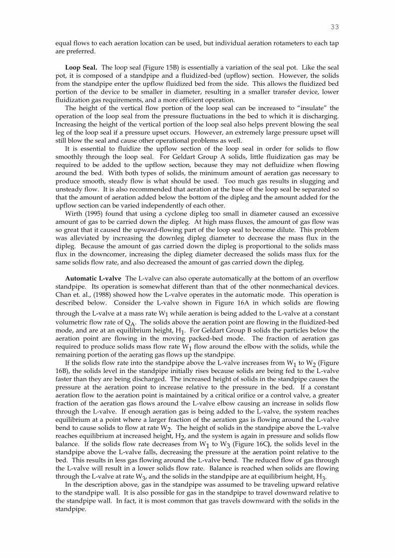
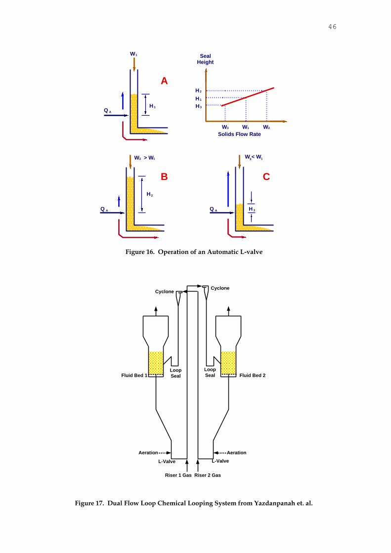
standpipe. Its operation is somewhat different than that of the other nonmechanical devices. Chan et. al., (1988) showed how the L-valve operates in the automatic mode. This operation is described below. Consider the L-valve shown in Figure 16A in which solids are flowing
through the L-valve at a mass rate W1 while aeration is being added to the L-valve at a constant
volumetric flow rate of QA. The solids above the aeration point are flowing in the fluidized-bed mode, and are at an equilibrium height, H1. For Geldart Group B solids the particles below the aeration point are flowing in the moving packed-bed mode. The fraction of aeration gas required to produce solids mass flow rate W1 flow around the elbow with the solids, while the remaining portion of the aerating gas flows up the standpipe.
If the solids flow rate into the standpipe above the L-valve increases from W1 to W2 (Figure 16B), the solids level in the standpipe initially rises because solids are being fed to the L-valve faster than they are being discharged. The increased height of solids in the standpipe causes the pressure at the aeration point to increase relative to the pressure in the bed. If a constant aeration flow to the aeration point is maintained by a critical orifice or a control valve, a greater fraction of the aeration gas flows around the L-valve elbow causing an increase in solids flow through the L-valve. If enough aeration gas is being added to the L-valve, the system reaches equilibrium at a point where a larger fraction of the aeration gas is flowing around the L-valve bend to cause solids to flow at rate W2. The height of solids in the standpipe above the L-valve reaches equilibrium at increased height, H2, and the system is again in pressure and solids flow balance. If the solids flow rate decreases from W1 to W3 (Figure 16C), the solids level in the standpipe above the L-valve falls, decreasing the pressure at the aeration point relative to the bed. This results in less gas flowing around the L-valve bend. The reduced flow of gas through the L-valve will result in a lower solids flow rate. Balance is reached when solids are flowing through the L-valve at rate W3, and the solids in the standpipe are at equilibrium height, H3.
In the description above, gas in the standpipe was assumed to be traveling upward relative to the standpipe wall. It is also possible for gas in the standpipe to travel downward relative to the standpipe wall. In fact, it is most common that gas travels downward with the solids in the standpipe.

34
The L-valve will not operate automatically over an infinite range of solid flow rates. At some increase in the solids flow rate in the example given above, not enough gas is available to fluidize the solids in the standpipe and they will defluidize. This causes the standpipe to fill with defluidized solids to a level which balances the pressure-drop loop. The automatic L-valve can also work if the solids in the standpipe are in the packed-bed mode. However, because the
P/Lg in a packed bed can vary over a wide range, the height of solids required for pressure sealing in the standpipe can also vary. This makes it difficult to control the height of solids in the standpipe, and they can easily back up into the cyclone, resulting in significant loss of material. To prevent this from happening, more aeration should be added to the L-valve.
As noted above, it is generally best to design a nonmechanical device by obtaining the required data in a cold-flow test unit using the actual solids to be transferred. If this is not possible, solids of similar size and density can be used. Nonmechanical valve or automatic nonmechanical device design has not yet reached a stage where it can be done analytically with great confidence. Cold modeling in a unit with 76- to 100-mm-diameter transfer lines is relatively inexpensive and minimizes operational problems when incorporating the device into a pilot plant or commercial system.
If possible, it is recommended that the basic pressure drop as a function of aeration relationship be obtained from a small L-valve test unit. Alternatively, these parameters may be extrapolated from the data presented by Knowlton and Hirsan (1978).
SINGLE AND MULI-LOOP SYSTEMS In a controlled solids recirculation system, a valve or some other means (such as solids
inventory) is used to control the solids flow rate in the system. For nonmechanically controlled systems, there are several ways to control the solids flow rate, and which one is used depends on whether the solids are Geldart Group A or Geldart Group B. Several different types of proposed nonmechanical solids flow systems are possible for multi-loop systems. The techniques used to control the solids flow rate around the systems are different. There are four ways to control the solids flow rate in nonmechanical systems:
1. Using a nonmechanical L-valve below a packed bed standpipe 2. Operating a riser at the choking velocity to control the solids flow rate 3. Using inventory control to change the level in an overflow fluidized bed standpipe 4. A combination of Methods 2 and 3 Consider the dual-loop system shown in Figure 17. This is a dual-loop chemical looping
system from Yazdanpanah et. al. (2011). The system shown uses two L-valves to control the solids flow rate around the system. L-valves can be used because the average particle size of the
solids in the system is approximately 320 m, which makes it a definite Geldart Group B material.
In any multi-looping system, only one control valve should be used to set the solids flow rate required. The other valve should be used to set the level of the solids. In this system, With the system shown, either L-valve could be used to control the solids flow around the system, and the other valve would be used to control the level of a fluidized bed. This system appears to be a good solid design. It does not need inventory manipulation to control the solids flow rate. Its main advantage over other forms of nonmechanical solids flow control to be discussed is that the solids flow rate can be controlled independently of modifying either the air or other fluidization gas flow rates. Its limitation is that it can be used with Group B and D solids only.
The system from Shimizu, et. .al. (2011) shown in Figure 18, is a different type of solids flow loop that uses solids inventory to control the solids flow rate around the system. The system shown is for a cold flow, bench-scale system. For a system such as the one shown, the solids flow rate achieveable in the system is dependent on the solids inventory in the system. A pressure balance around the unit gives:
Psealpot + Priser + Pcy = Psp = Hsp sp (15)
If it is assumed that the gas velocity in the riser is constant, if the solids flow rate increases,
the pressure drop across the riser will increase, and the cyclone pressure drop will also likely

35
increase. This means that the pressure drop across the standpipe must increase to balance the pressure drop increase from the riser and cyclone. To balance the increase in pressure drop in the riser and cyclone, the height of solids in the standpipe must increase. However, the standpipe is operating as an overflow fluidized bed standpipe, and the height of the standpipe times the solids/gas suspension density in the standpipe is that required to balance the pressure drop in the riser, cyclone and loop seal. If the solids flow rate increases to the riser, the riser inventory will increase. The extra riser solids cannot be supplied by the fluidized bed because the standpipe is an overflow standpipe. This means that the solids will have to be supplied by the standpipe. But, the solids level in the standpipe cannot be increased because the inventory in the system is fixed. Therefore, solids must be added to the system to allow the increased solids flow rate.
This type of system can be used, but the disadvantages of it are: 1) at high pressures, it will be difficult to add and remove solids to change the solids flow rate as required, and 2) the solids flow rate change cannot be made immediately. However, this system can be used with Geldart Group A solids (as well as Geldart Group B solids), but it is not as responsive and it is more complex to operate than the L-valve system described above.
A third type is system is shown in Figure 19. This dual-loop system was described by Guio-Perez et. al (2011) that was used in a cold flow unit model simulating a chemical looping combustion system. In this system, air added to the riser is used to control the solids flow rate in the system. How this is accomplished is indicated in Figure 20. This figure shows a generalized phase diagram for a vertical pneumatic conveying (riser) system. Riser pressure-drop-per-unit-length is plotted versus the superficial gas velocity in the riser for three different solids mass fluxes. Each of the “U-shaped” curves in Figure 20 correspond to a constant solids mass flux in the riser. The bottom curve is the lowest mass flux (G1) and the upper curve corresponds to the highest solids mass flux shown (G3).
A low velocity for each of the solids mass flux curves, the curve rises rapidly to an asymptotic value of a velocity called the choking velocity (Uch). The choking velocity represents the lowest velocity that the riser can operate at that solids mass flux and still operate in dilute-phase flow. Operating at lower riser fluxes cause the riser to choke and revert to dense-phase flow. Assume that the riser is operating at a mass flux of G1 at a riser velocity Uch1. The riser cannot operate at a higher solids flux and still remain in the dilute-phase regime. To increase the solids flux in the system, the gas velocity in the riser must be increased. This will allow the riser to operate at a mass flux of G2 at a riser velocity corresponding to Uch2.
In the manner shown above, the solids flow rate around the system can be controlled. However, as the solids flow rate in the system is increased, the inventory in the riser will increase slightly as well. This will cause the addition solids required by the riser to be shifted from the other riser in the unit, or more solids (inventory) will have to be added to the system. As with the previous system from Shimizu et. al. (2011), this unit can operate with Group A solids as well as Group B solids.
Another L-valve controlled system is the chemical looping single loop system from Fan and co-workers (2010) from The Ohio State University (Figure 21). This system employs an L-valve to control the solids flow rate around the single loop, and does not require any inventory change. The solids particle size for this system ranges from about 1500 to 3000 microns, so an L-valve is a logical choice to control the solids flow rate. This system has good solids flow control. As with the system employed by Yazdanpanah et. al. (2011), solids flow control can be achieved without changes in the transport gas flow rates in the unit. This makes the system easier to control.
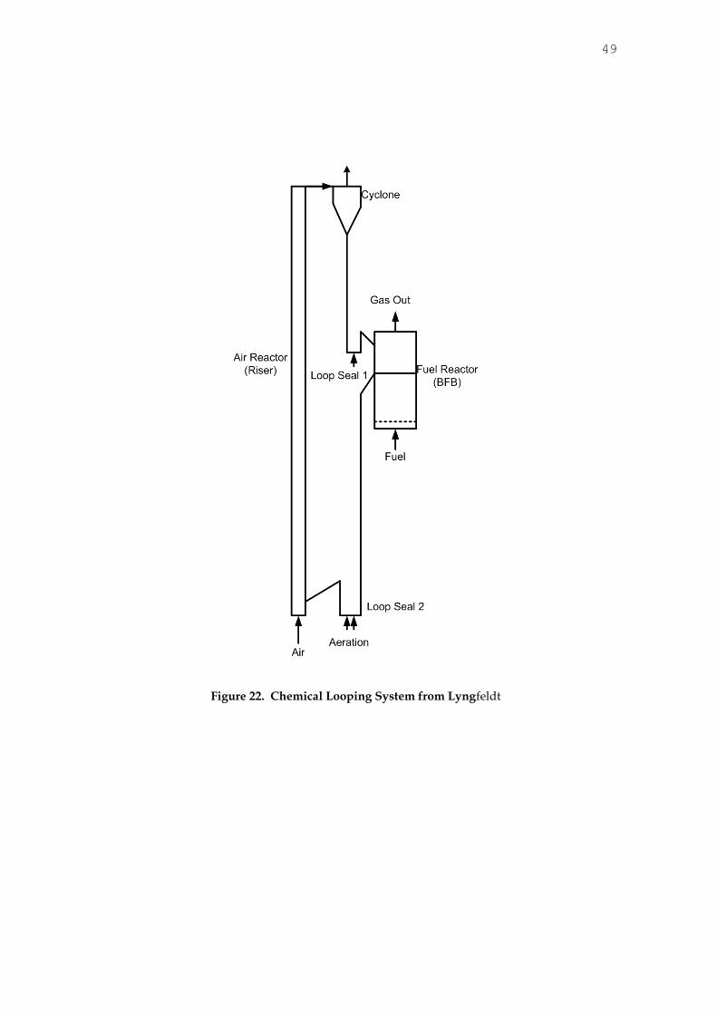
A final chemical looping system is shown in Figure 22, from Lyngfeldt (2010). This system is a single loop system employing two fluidized beds. In order to change the solids flow rate with this type of system (where solids are not one of the reactants), the system solids flow rate inventory is again required to change, as described above. The system is slightly different, but the concept is the same. In order to change the solids flow rate significantly, the inventory of the system must be changed. It must be increased to increase the solids flow rate, and decreased to decrease the solids flow rate.
36
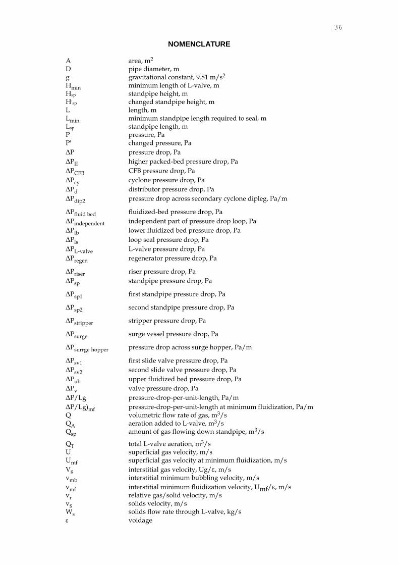
NOMENCLATURE A area, m2 D pipe diameter, m g gravitational constant, 9.81 m/s2 Hmin minimum length of L-valve, m Hsp standpipe height, m H'sp changed standpipe height, m L length, m Lmin minimum standpipe length required to seal, m Lsp standpipe length, m P pressure, Pa P' changed pressure, Pa
P pressure drop, Pa
PII higher packed-bed pressure drop, Pa
PCFB CFB pressure drop, Pa
Pcy cyclone pressure drop, Pa
Pd distributor pressure drop, Pa
Pdip2 pressure drop across secondary cyclone dipleg, Pa/m
Pfluid bed fluidized-bed pressure drop, Pa
Pindependent independent part of pressure drop loop, Pa
Plb lower fluidized bed pressure drop, Pa
Pls loop seal pressure drop, Pa
PL-valve L-valve pressure drop, Pa
Pregen regenerator pressure drop, Pa
Priser riser pressure drop, Pa
Psp standpipe pressure drop, Pa
Psp1 first standpipe pressure drop, Pa
Psp2 second standpipe pressure drop, Pa
Pstripper stripper pressure drop, Pa
Psurge surge vessel pressure drop, Pa
Psurrge hopper pressure drop across surge hopper, Pa/m
Psv1 first slide valve pressure drop, Pa
Psv2 second slide valve pressure drop, Pa
Pub upper fluidized bed pressure drop, Pa
Pv valve pressure drop, Pa
P/Lg pressure-drop-per-unit-length, Pa/m
P/Lg)mf pressure-drop-per-unit-length at minimum fluidization, Pa/m Q volumetric flow rate of gas, m3/s QA aeration added to L-valve, m3/s Qsp amount of gas flowing down standpipe, m3/s
QT total L-valve aeration, m3/s U superficial gas velocity, m/s Umf superficial gas velocity at minimum fluidization, m/s
Vg interstitial gas velocity, Ug/, m/s vmb interstitial minimum bubbling velocity, m/s
vmf interstitial minimum fluidization velocity, Umf/, m/s vr relative gas/solid velocity, m/s vs solids velocity, m/s Ws solids flow rate through L-valve, kg/s
voidage

37
mf voidage at minimum fluidization
dip2 secondary cyclone dipleg density, kg/m3
mf fluidized-bed density at minimum fluidization, kg/m3
p particle density, kg/m3
REFERENCES
1. Knowlton TM and Hirsan I. 1978. L-valves characterized for solids flow. Hydrocarbon Processing . 57:149-161.
2. Knowlton TM, Leung LS and Hirsan I. 1978. The effect of aeration tap location on the performance of a J-valve. In: Davidson, JF Keairns, DL, eds. Fluidization II. 1978. p. 128-136.
3. Campbell DL, Martin HZ and Tyson CW. 1948. US Patent 2,451,803
4. Wirth KE. Fluid mechanics of the downcomer in circulating fluidized beds. 1995. Proceedings of the Eighth International Conference on Fluidization, Tours, France. 1995.
5. Chan I, Findlay J and Knowlton TM. 1988. Operation of a Nonmechanical L-valve in the automatic mode. Paper presented at the Fine Particle Society Meeting, Santa Clara, CA..
6. Yazdanpanah, M., Hoteit, A, Forret, Gauthier, T and Delebarre, A., Gas Tracer Study in a Nonmechanical L-valve, In: Proceedings of the 10th International Conference on Circulating Fluidized Beds and Fluidization Technology, T. Knowlton, editor, p. 98-105, Engineering Conferences International, Bend, Oregon, May, 2011.
7. Shimizu, T, Takahasi, T, Narisawa, H., Murakami, Y., Li, L and Kim, H. 2011. CaO Looping Cycle for CO2 Separation, Proceedings of the 10th International Conference on Circulating Fluidized Beds and Fluidization Technology, T. Knowlton, editor, p. 329-336, Engineering Conferences International, Bend, Oregon, May, 2011
8. Guio-Perez, D.D., Marx, K, Proll, T and Hofbauer, H. 2011. Fluid Dynamic Effects of Ring-Type Internals in a Dual Circulating Fluidized Bed System, Proceedings of the 10th International Conference on Circulating Fluidized Beds and fluidization Technology, T. Knowlton, editor, p. 369-376, Engineering Conferences International, Bend, Oregon, May, 2011.
9. Fan, L.S., Chemical Looping Processes, Keynote address. 2010. 1st International Conference on Chemical Looping, Lyon, France, March 17-19, 2010.
10. Lyngfeldt, A., Oxygen Carriers for Chemical Looping Combustion, Keynote Address. 2010. 1st International Conference on Chemical Looping, Lyon, France, March 17-19, 2010.
38
L-Valve J-Valve Approximated J-Valve
A B C
Figure 1. The Most Common Nonmechanical Valves
QT
Qext
Qsp
QT
Qsp
QT
=
Qext
Qext + Qsp QT = Qext - Qsp
Occurs With Small Particle Sizes
and/or At High Solids Flow Rates
Occurs With Large Particle Sizes
and/or At Low Solids Flow Rates
Most Common Situation
Figure 2. Gas Flow Around an L-valve
39
P
>
Case I Case II
Gas FlowingUpward
to Pipe Wall
Gas FlowingRelative
to Pipe Wall
V
V V
g
sr
2
DownwardRelative
Vs
Vr
Vg
P1
P1P2
Vr = Vs - Vg
Vr = Vs - VgVr = Vs - Vg(- )
Vr = Vs + Vg
+
Positive Direction
is Downward
Figure 3. Gas Flow Direction in a Standpipe
Gas Velocity
Pre
ssu
re-D
rop
-Per-
Un
it-L
en
gth
P/Lg)mf
Packed-BedRegion
Umf
Fluidization Curve - Group A Solids
Umb
Fluidized
Non-Bubbling
Region
Fluidized
Bubbling
Region
Figure 4. Fluidization Curve for Group A Solids
40
Relative Velocity
Pre
ssu
re-D
rop
-Per-
Un
it-L
en
gth
P/L)mf
Packed-Bed
Region
Fluidized-Bed Region
(Bubbling)
Vmf
Fluidization Curve - Group B Solids
Figure 5. Fluidization Curve for Group B Solids
OVERFLOW UNDERFLOW
Underflow and Overflow Standpipes
Figure 6. Overflow and Underflow Standpipes
41
PLB
PUB
Hsp
Pgrid
P1
P2
PLB
PUB
Hsp
Pgrid
P
1
P2PRESSURE
HE
IGH
T
PRESSURE
HE
IGH
T
Pressure Profile in ColumnPressure Profile in Standpipe
P PP 2
'
P'2
P1
Figure 7. Fluidized Overflow Standpipe Operation
Pgrid
HEIGHT
PRESSURE
Pressure Profile in Column
Pressure Profile in Standpipe
P/L
Relative Velocity, V r
Pvalve
VrVr
P/L 2
P/L 1
Underflow Packed-Bed Standpipe Operation
L
P1
P2
P1 P2 P2'
I II
III
V V
V
V
V
V
rr
s sg g
III
Figure 8. Operation of a Packed-Bed Underflow Standpipe
42
PHopper
Aeration
GasOutlet
PStandpipe
PL-Valve
PBed
PPiping
PStandpipe+ PHopper = PBed + PPiping + PL-Valve
L-Valve System Pressure Balance
PStandpipe= K + PL-Valve
0 K
Figure 9. Pressure Balance for L-valve System
0 0.2 0.4 0.6 0.8 1 1.2 1.4 1.6 1.80
2
4
6
8
10
12
14
16
18
20
L-Valve Aeration Rate, ACFM
So
lid
s F
low
Rate
, T
ho
usan
ds o
f lb
/h
Material: Sand (260 microns)
Aeration Gas: Nitrogen
B
1
2
3
4
5Tap
Height Above
Centerline, in
1
2
3
4
5 24
18
12
6
0
B
Figure 10. Effect of Aeration Location on L-valve Operation

43
Figure 11. Example of L-valve Operation
Pfb
+ Psp
= PL-valve
+ Priser
If Pfb
< PL-valve
+ Priser
Then Relative Velocity as in 1
Occurs
If Pfb
> PL-valve
+ Priser
Then Relative Velocity as in 2
Occurs
44
Combustor
Gas Out
Cyclone
Feed Vessel
Conveying Steam
L-Valve
Dilute-PhaseDryer
Hot BedSand
Aeration
Figure 12. Feeding Into a Riser With an L-Valve
The L-Valve Can be Designed to Prevent
System Gas from Exiting the Reactor
V Vg s
Figure 13. L-valve Flow in a Pipe for no Gas Flow From the Reactor
45
It is also Possible to Prevent Aeration Gas
from Entering the Reactor
V Vg s
Figure 14. L-valve Flow in a Pipe for no Gas Flow Into the Reactor
A) Seal Pot B) Loop Seal
Fluidizing GasFluidizing Gas
Figure 15. Schematic Drawings of: A) Seal Pot and B) Loop Seal
46
W W W
Solids Flow Rate
W
QH 1
1
A
W > W12 W < W 13
H 2
Q A Q A H 3
SealHeight
1 23
H 1
H 2
H 3
A
B C
Figure 16. Operation of an Automatic L-valve
AerationAeration
L-ValveL-Valve
Riser 2 GasRiser 1 Gas
Fluid Bed 2
Loop
SealLoop
SealFluid Bed 1
CycloneCyclone
Figure 17. Dual Flow Loop Chemical Looping System from Yazdanpanah et. al.

47
Figure 18. Overflow Solids Flow Loop System from Shimizu et. al.
Loop
Seal
3
Loop
Seal
1
Cyclone 2
Cyclone 1
Aeration
Control
Air
Riser
Loop
Seal
2
Aeration
Aeration
Fuel
Air
Figure 19. Dual-Loop Chemical Looping System from Guio-Perez et. al

48
Superficial Gas Velocity, U
Ris
er
Pre
ssu
re D
rop
Per
Un
it L
en
gth
G = G1
2
U For Curve 1ch
2
G = G1
3
G = G
3
Figure 20. How Choking Can be Used to Control the Solids Flow Rate
Figure 21. Moving Packed-Bed Chemical Looping System from Fan et. al.
49
Figure 22. Chemical Looping System from Lyngfeldt