Embed Size (px)
Citation preview
NONWOVEN PAVING FABRICS STUDY
FINAL REPORT
Submitted to:
Industrial Fabrics Association International Geotextile Division
Prepared by:
Maxim Technologies, Inc. 4150-B Freidrich Lane
Austin, Texas 78744
December 1997
TABLE OF CONTENTS
EXECUTIVE SUMMARY
1. INTRODUCTION......................................................................................................... 1
2. REVIEW OF APPLICATIONS..................................................................................... 1
2.1 Chip Seals (Surface Dressing) of Subgrade Soils ...........................................................................................2
2.2 Chip Seals (Surface Dressings) For Existing ACPavements.........................................................................3
2.3 AC/Fabric Overlay of Existing PCC Pavements............................................................................................3
2.4 AC/Fabric Overlay of Existing ACPavements ...............................................................................................4
2.5 Conclusions........................................................................................................................................................6
3. CONSIDERATIONS AND SPECIAL LIMITATIONS OF USE..................................... 6
3.1 Existing Pavement Condition ..........................................................................................................................6
3.2 Inadequate Base/Subgrade Support................................................................................................................7
3.3 Environmental Factors.....................................................................................................................................7
4. DEVELOPMENT OF PAVEMENT DESIGN MODEL.................................................. 8
4.1 Research Approach Technique for Pavement Design Utilizing Paving Fabric...........................................8
4.2 Structural Design Model and Applications ..................................................................................................12
4.3 Environmental Design Module and Applications ........................................................................................14
4.4 Final Combined Model...................................................................................................................................15
5. CONSIDERATION OF FABRICS IN A PAVEMENT MANAGEMENT SYSTEM...... 15
5.1 Requirements ..................................................................................................................................................16
5.2 Summary .........................................................................................................................................................18
6. CONCLUSIONS........................................................................................................ 18
i 7. REFERENCES.......................................................................................................... 19

SKETCHES TABLES FIGURES
ii
EXECUTIVE SUMMARY
Under contract with the Geotextile Division of the Industrial Fabrics Association International, Maxim Technologies, Inc. investigated the use, performance, and design considerations for asphalt membrane interlayer systems utilizing a nonwoven paving fabric. This is a widely used technology with more than 15,000 lane miles installed each year in North America. Although performance of the system has obviously sustained this amount of annual usage, very little controlled testing and scientific verification has been performed on the system since its inception 30 years ago. Maxim chose to investigate the paving fabric interlayer system by reviewing all available literature on the subject as well as by interviewing many experts who have worked with the system for years. Enough data was available on which to form a strongly backed technical opinion on the effectiveness of nonwoven paving fabric systems. The results of this “expert system” analysis of nonwoven paving fabrics are presented in this report and summarized in this executive summary of the report. The literature review examined more than 200 reports on the use and performance of nonwoven paving fabric interlayer systems. This effort was followed by Maxim’s personal interviewing of over 50 expert users of the paving fabric system. This data collection also revealed a data base of over 100 pavement sections on which performance of the system was monitored. The data search found 4 principal end use applications of the nonwoven paving fabric system: 1) Paving fabric with a chip seal over unpaved roads and subgrades, 2) Paving fabric and chip seal over existing AC (Asphalt Cement Concrete) pavements, 3) Paving fabric and AC overlay over existing PCC (Portland Cement Concrete) pavements, and 4) Paving fabric and AC overlay over existing AC pavements. Most applications included an asphalt cement concrete overlay (Conditions 3 and 4) and the comments of this summary are based on those conditions. Performance of the nonwoven paving fabric system was generally measured by evaluating the condition of overlays placed over the system compared to overlays where the system was not used. This performance was reported in two ways. It was reported by comparing the performance of the paving fabric/overlay sections to control sections with no paving fabric or control sections with thicker AC overlays, for a given period of time. The second way the performance was compared was by looking at the difference in service life of the different overlay treatments. As a result of our investigation we found that the inclusion of a nonwoven paving fabric interlayer system significantly improves the performance of AC overlays. As reported by the experts, this performance improvement is a result of both the waterproofing capabilities and the stress absorption capabilities of the paving fabric system. When comparing thinner AC overlays with the nonwoven paving fabric interlayer system to thicker overlays without the system, there was a good consensus among the literature and the interviewed experts. Their conclusion was that the paving fabric system gives additional overlay performance equivalent to increased overlay thickness of 1.0 to 1.8 inches with an average performance equivalency of approximately 1.3 inches. The paving fabric interlayer is not meant to be a structural layer to make up pavement structural thickness deficiencies. Also,
E-1
this amount of AC overlay equivalency does assume that the existing pavement is stable, the paving fabric system is properly installed, and a minimum overlay thickness of 1.5 inches is placed. However, even at this thickness the inclusion of fabric has been shown to increase service life. In almost all reports where the paving fabric system was shown to be of limited or no benefit, either the covered pavement was too deteriorated or too thin of an overlay was used. In northern climates, the recurrence of thermal cracking often occurred even over a paving fabric system. This is because the thermal expansion and contraction is occurring within the overlay itself causing cracking. Thermal cracking is not generally a reflective cracking. It was found, however, that although some thermal cracking returned, the pavement was still waterproofed to minimize freeze/thaw damage and overall pavement service life was improved. The second phase of the project was to develop a pavement design model which is consistent with the actual monitored performance of the nonwoven paving fabric interlayer system. The design parameters are based on the field verified benefits of the system. These benefits are provided in two general ways, structural and environmental. The structural design parameters are based on how the use of a paving fabric system effectively improves the structural performance of a pavement system. This structural improvement is due to the waterproofing function of the paving fabric system and due to the stress absorbing interlayer function. The effective strength of the road base components is improved by controlling the precipitation infiltration with the pavement moisture barrier paving fabric system. Both AC and PCC pavements are quite permeable and will normally allow up to 50% of all precipitation to infiltrate to damage the base and subgrade. Stopping the moisture infiltration achieves the same result as effective base drainage--to keep moisture from holding in the base. By maintaining a lower moisture content in the roadbase materials the effective strength or support provided by that roadbase is improved. This improvement is quantified in AASHTO’s Design for Flexible Pavements, 1993. Well drained (dry) bases provide up to 2.5 times the pavement support of poorly drained (wet) pavement bases. The waterproofing benefit of the paving fabric system was conservatively assigned design parameters comparable to a one level increase in drainage coefficients by the AASHTO design method. Increasing the effective strength of the road base materials can lower the strength/thickness requirements for the overlay. The second structural benefit afforded by the paving fabric system is the stress absorption function it provides. An installed asphalt saturated nonwoven paving fabric layer allows for slight differential movement between the top of the old pavement and the bottom of the AC overlay. This retards the development of reflective cracking since some movement associated with old cracking will be absorbed by the paving fabric layer and not transferred up into the overlay. The creation of a layered pavement system with a paving fabric interlayer also minimizes harmful tensile stresses. Overlays directly placed on old pavement surfaces simply create a thicker monolithic pavement while overlays over a nonwoven paving fabric system allow a bonded but layered system with less tensile stress per layer. The paving fabric interlayer allows many times the amount of traffic loading flexures before pavement cracking occurs. This is similar to the flexibility of laminated timbers versus solid timbers.
E-2
The effect of this low modulus paving fabric interlayer was input into the structural analysis algorithm along with the increased moduli of the pavement base layers with lower moisture contents. The combined effect varied somewhat based on pavement design and thickness of pavement and base layers. However, the average structural effect on the pavement by the nonwoven paving fabric system is equivalent to placing an additional overlay thickness of about 0.8 inches. This effect ranged from about 0.5 to 1.75 inches in equivalent overlay thickness benefits. Changes in environmental factors due to the presence of a nonwoven paving fabric interlayer system, supported the second area of design parameters verifying the performance of the system. There are numerous environmental factors which influence pavement design and pavement performance. The moisture control function of the paving fabric system affects the environmental parameters of; general subgrade moisture conditions, swelling soils and freeze/thaw susceptible soils. The control of these factors was input into algorithms which calculated the equivalent overlay thickness attributable to the paving fabric system. The results varied slightly due to the soil types, geographic environmental zone and depth to rigid layer, but the environmental equivalent thickness benefit is generally about 0.5 inches. The effect of the non-woven fabric is therefore on average 1.3" with 0.5" environmental equivalent thickness benefit and 0.8" structural equivalent thickness benefit. This compares well with literature review results. This is significant since the cost of non-woven paving fabric in place is approximately equivalent to 0.5" of hot mix asphalt concrete resulting to a savings equivalent to the cost of at least 0.8" of hot mix asphalt concrete. The algorithms representing both the structural benefit and the environmental benefit of a nonwoven paving fabric system are additive and make up the basis for the design model. The design model agrees with the field performance data reviewed. Once this design model was developed and verified, a regression equation was created that could be easily adopted into a typical pavement management system. This equation is presented in the report. It is the professional opinion of the authors that nonwoven paving fabric systems provide a technically sound, economical option which should be considered when evaluating AC overlays. Therefore, it is an important input factor for pavement management and should be included in pavement management systems. The use of nonwoven paving fabrics beneath chip seals was reported by the literature and experts to give excellent results, but the benefit in this application was not quantified by a design model in this report.
E-3
NONWOVEN PAVING FABRICS STUDY
FINAL REPORT
1. INTRODUCTION Nonwoven paving fabrics have been used in asphalt overlays for over three decades. Even though these nonwoven geotextiles have been widely and successfully used in a variety of design and construction situations, the applications of paving fabric have been generally characterized by limited documentation of their performance. In addition the present pavement structural design methods do not provide a rational basis for assessing or evaluating the benefits of inclusion of paving fabric in a pavement structural section. These two factors, i.e. limited performance data and lack of a design approach, have resulted in a lack of consistent application of paving fabrics, and significant regional differences in the usage levels of nonwoven paving fabric. These same limitations have also resulted in a lack of consistent consideration of the paving fabric option in pavement management systems. Because of this dilemma, a Paving Fabrics Task Group was formed within the Geotextile Division of the Industrial Fabrics Association International (IFAI) to summarize the uses, benefits and applications of nonwoven geotextiles for pavement membrane interliner systems, commonly referred to as paving fabrics. This Paving Fabrics Task Group selected Maxim Technologies, Inc. to undertake a study to define the applications, performance, benefits, extent of usage of nonwoven paving fabrics and to recommend design criteria for its application in pavement management systems.
2. REVIEW OF APPLICATIONS Nonwoven paving fabrics have been used in a variety of pavement structures ranging from chip seals (or surface dressings) with paving fabric placement directly on the base materials to rehabilitation overlays with fabric placed directly upon existing distressed asphalt concrete (AC) and/or Portland cement concrete (PCC) pavements. In the former case, the paving fabric was essentially used to provide waterproofing control against infiltration of free surface water into the base and subgrade soils, while in the latter case the paving fabric was additionally used to retard the transmission of existing cracks and distresses. In both cases the geotextile fabric provides not only control of surface water infiltration into the underlying pavement structure but also control of evaporation processes over the long term; yielding a fairly uniform moisture content in the supporting subgrade soils. The literature review examined more than 200 reports on the use and performance of nonwoven paving fabric interlayer systems. This effort was followed by Maxim’s personal interviewing of over 50 expert users of the paving fabric system. This data collection also reviewed a data base of over 100 pavement sections on which performance of the system was monitored. The data search
1
found 4 principal end use applications of the nonwoven paving fabric system: 1) Paving fabric with a chip seal over unpaved roads and subgrades, 2) Paving fabric and chip seal over existing AC (Asphalt Cement Concrete) pavements, 3) Paving fabric and AC overlay over existing PCC (Portland Cement Concrete) pavements, and 4). Paving fabric and AC overlay over existing AC pavements. Most applications included an asphalt cement concrete overlay (Conditions 3) and 4) and the comments of this summary are based on those conditions. These four basic applications are illustrated in Figure 1.
2.1 Chip Seals (Surface Dressing) of Subgrade Soils Perhaps the simplest, yet innovative, use of paving fabrics involved their use as an interlayer between the chip seal (or surface dressing) and native material base layers or insitu subgrade soils. This application has been effectively used since 1985 in several countries (see Table 1) including Australia, France, Canada and French Guiana. In each case summarized in Table 1, the sections with fabric performed better than those control sections produced by normal construction procedures. The fabric sections generally exhibited less distress or reflection cracking. In four of the five cases it was emphasized that subgrade deformation was experienced in the control sections, but that little or no destructive deformations developed in the fabric sections. The subgrade soils underlying the fabric sections apparently remained firm and provided uniformly sufficient subgrade support. This demonstrates the effectiveness of the water proofing characteristics of the fabrics on subgrade soils. The rationale for the development of uniform subgrade support under these circumstances can be better understood in reviewing the moisture distribution with depth for the Ivanhoe, Australia case study (Ref. 2). In Figure 2, moisture distributions are defined in terms of depth below the top of seal or existing subgrade surface associated with the insitu moisture content as a percentage of the standard optimum moisture content. The results shown were acquired in August 1988, about twenty (20) months after construction and after two months of wet weather (about 4 inches of rain in the months of June and July). It can be seen from the results that the moisture content for the soils underlying the seal/fabric sections was 15 to 25 percent lower than the moisture contents for adjacent insitu soils located outside the influence of the fabric placement. During the Ivanhoe, Australia case study the moisture content of the soils underlying the fabric sections remained within +2 percent regardless of the season of the year (i.e. between the dry and wet seasons). From these results, the fabric provided not only protection from infiltration of free surface water but it also maintained a uniform subgrade moisture regime through control of subgrade moisture gain and loss. The maintenance of moisture contents at about 20 percent below the standard optimum conditions from season to season certainly provides the explanation for the performance of the seal/fabric trial sections. This difference in moisture contents (i.e. between optimum and 80 percent optimum) could result in a 2 to 3 times increase in CBR. If the often stated relationship between modulus and CBR (i.e. E = 1500 * CBR) is used as a criteria, the subgrade modulus, over a short period of time, could be more than doubled in magnitude as a result of the application of a paving fabric to a pavement structural section.
2
2.2 Chip Seals (Surface Dressings) For Existing AC Pavements Chip seals (surface dressings) incorporating paving fabric have been used to repair existing ACpavements in the United States and the United Kingdom, beginning about 1984-85 (see Table 2). The challenge related to chip seals (surface dressings) with fabric appear to be the long term bonding of the stone to the fabric. In five of the six cases cited in Table 2, the chip seals (surface dressing) sections with fabric performed better than the chip seal (surface dressing) sections alone. In these instances the fabric generally remained intact even though some stone loss had occurred. As stated in Reference 8, the use of a geotextile in a chip seal (or surface dressing) offers the potential to prolong the useful life of distressed pavements through prevention of water infiltration and maintenance of granular base and subgrade strengths.
2.3 AC/Fabric Overlay of Existing PCC Pavements An application of paving fabric in the rehabilitation of existing PCC pavements was evaluated at the sixteen sites identified in Table 3. Fourteen sites are located within the United States in eight states and the remaining sites are located in Belgium and Austria. Almost half (i.e. 7) of the sites were evaluated for more than 5 years and three of the California, USA sites were observed for 10 or more years. A review of the results presented in Table 3 shows that the use of a paving fabric in the rehabilitation of PCC pavements resulted in a retardation in the development of reflection cracking. In addition the fabric appeared to be effective when used to correct a specific distress condition such as popouts (Illinois: References 15 and 22). However, paving fabric is not entirely effective in combating the reflection of existing transverse cracks or joints when there is existing excessive vertical movement or high deflection. A case study in Georgia (Ref. 11) provides important information concerning the impact in rehabilitation overlays involving AC overlay thickness alone (Figure 3) and the combination of AC overlay thickness with fabric (Figure 4) on the eventual development of reflection cracking related to original conditions of PCC pavements. From Figure 3 it can be seen that reflection cracking at a 60 percent level can be anticipated at one year for a 2" AC overlay; three years for a 4" overlay and nine years for a 6" AC overlay. In the same study (Ref. 11) the impact of the combination of AC overlay with paving fabric was also investigated and the results are presented in Figure 4. The 60 percent performance levels, based on percent reflection cracking, was three years for a 2" AC overlay with fabric, and six years for a 4" AC overlay with fabric. The 60 percent performance time for the 6" AC overlay with fabric, could not be reasonably be projected because of the low level of percent reflection cracking achieved during the observation period. It can be noted from Figures 3 and 4 that the addition of a paving fabric to a 2" AC overlay increased the time to 60 percent reflection cracking from one year with no fabric to three years with fabric. With this information in mind the results from Figures 3 and 4 were combined in Figure 5 to allow a visual assessment of the benefit of paving fabric in the rehabilitation overlay of existing PCC pavements. From Figure 5, it is apparent that the 2" AC/fabric section is equivalent to the 4" AC control section since one plots practically on top of the other. The inference is that an equivalent
3
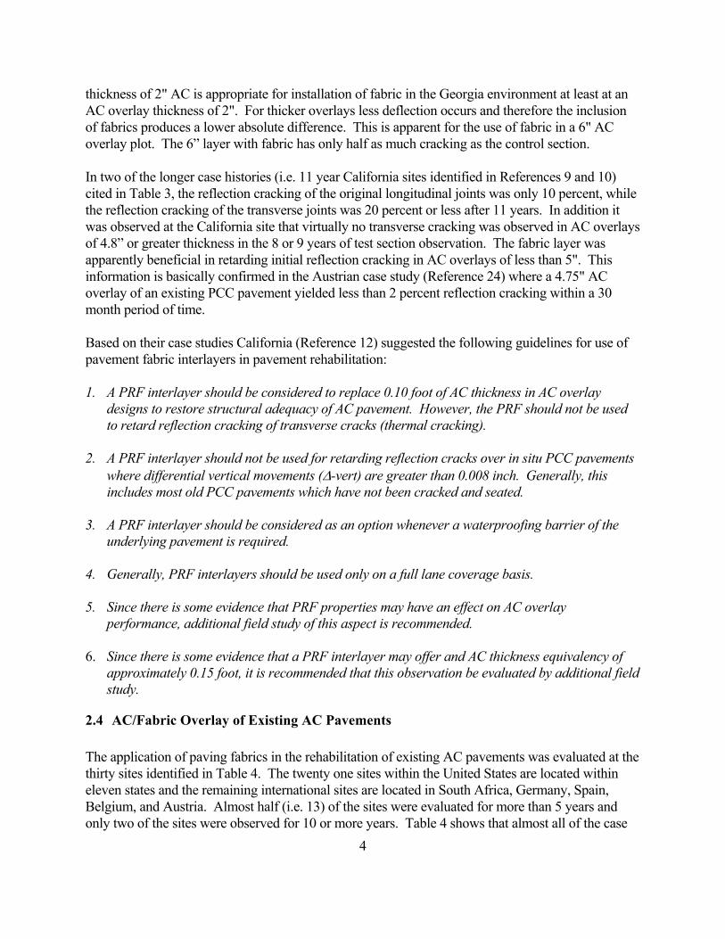
thickness of 2" AC is appropriate for installation of fabric in the Georgia environment at least at an AC overlay thickness of 2". For thicker overlays less deflection occurs and therefore the inclusion of fabrics produces a lower absolute difference. This is apparent for the use of fabric in a 6" AC overlay plot. The 6” layer with fabric has only half as much cracking as the control section. In two of the longer case histories (i.e. 11 year California sites identified in References 9 and 10) cited in Table 3, the reflection cracking of the original longitudinal joints was only 10 percent, while the reflection cracking of the transverse joints was 20 percent or less after 11 years. In addition it was observed at the California site that virtually no transverse cracking was observed in AC overlays of 4.8” or greater thickness in the 8 or 9 years of test section observation. The fabric layer was apparently beneficial in retarding initial reflection cracking in AC overlays of less than 5". This information is basically confirmed in the Austrian case study (Reference 24) where a 4.75" AC overlay of an existing PCC pavement yielded less than 2 percent reflection cracking within a 30 month period of time. Based on their case studies California (Reference 12) suggested the following guidelines for use of pavement fabric interlayers in pavement rehabilitation: 1. A PRF interlayer should be considered to replace 0.10 foot of AC thickness in AC overlay
designs to restore structural adequacy of AC pavement. However, the PRF should not be used to retard reflection cracking of transverse cracks (thermal cracking).
2. A PRF interlayer should not be used for retarding reflection cracks over in situ PCC pavements
where differential vertical movements (∆-vert) are greater than 0.008 inch. Generally, this includes most old PCC pavements which have not been cracked and seated.
3. A PRF interlayer should be considered as an option whenever a waterproofing barrier of the
underlying pavement is required. 4. Generally, PRF interlayers should be used only on a full lane coverage basis. 5. Since there is some evidence that PRF properties may have an effect on AC overlay
performance, additional field study of this aspect is recommended.
6. Since there is some evidence that a PRF interlayer may offer and AC thickness equivalency of approximately 0.15 foot, it is recommended that this observation be evaluated by additional field study.
2.4 AC/Fabric Overlay of Existing AC Pavements The application of paving fabrics in the rehabilitation of existing AC pavements was evaluated at the thirty sites identified in Table 4. The twenty one sites within the United States are located within eleven states and the remaining international sites are located in South Africa, Germany, Spain, Belgium, and Austria. Almost half (i.e. 13) of the sites were evaluated for more than 5 years and only two of the sites were observed for 10 or more years. Table 4 shows that almost all of the case
4
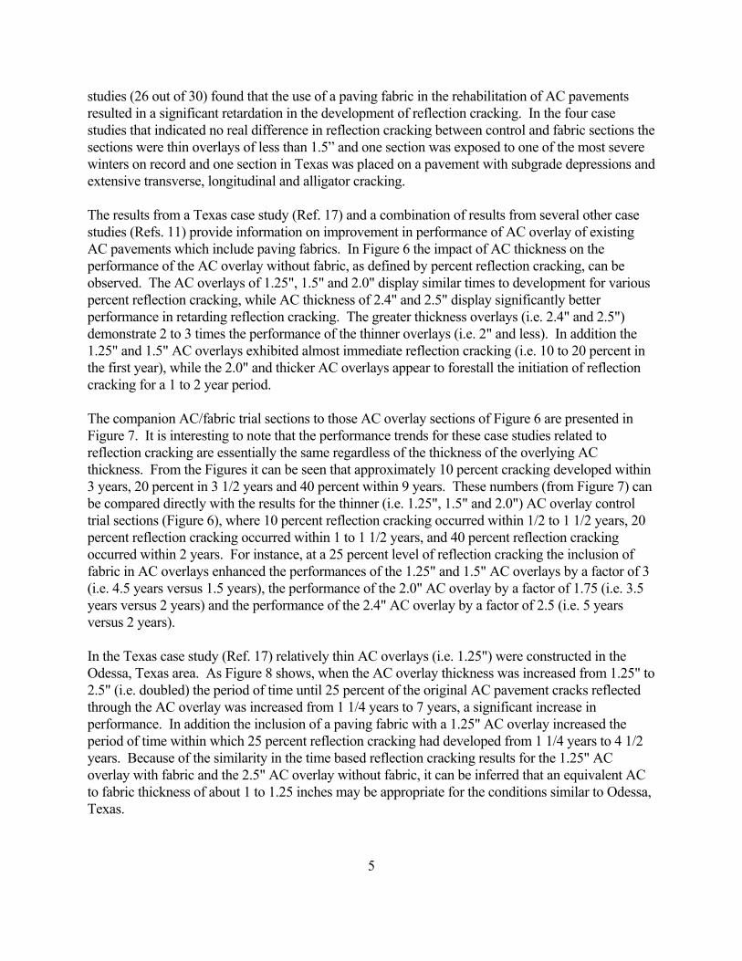
studies (26 out of 30) found that the use of a paving fabric in the rehabilitation of AC pavements resulted in a significant retardation in the development of reflection cracking. In the four case studies that indicated no real difference in reflection cracking between control and fabric sections the sections were thin overlays of less than 1.5” and one section was exposed to one of the most severe winters on record and one section in Texas was placed on a pavement with subgrade depressions and extensive transverse, longitudinal and alligator cracking. The results from a Texas case study (Ref. 17) and a combination of results from several other case studies (Refs. 11) provide information on improvement in performance of AC overlay of existing AC pavements which include paving fabrics. In Figure 6 the impact of AC thickness on the performance of the AC overlay without fabric, as defined by percent reflection cracking, can be observed. The AC overlays of 1.25", 1.5" and 2.0" display similar times to development for various percent reflection cracking, while AC thickness of 2.4" and 2.5" display significantly better performance in retarding reflection cracking. The greater thickness overlays (i.e. 2.4" and 2.5") demonstrate 2 to 3 times the performance of the thinner overlays (i.e. 2" and less). In addition the 1.25" and 1.5" AC overlays exhibited almost immediate reflection cracking (i.e. 10 to 20 percent in the first year), while the 2.0" and thicker AC overlays appear to forestall the initiation of reflection cracking for a 1 to 2 year period. The companion AC/fabric trial sections to those AC overlay sections of Figure 6 are presented in Figure 7. It is interesting to note that the performance trends for these case studies related to reflection cracking are essentially the same regardless of the thickness of the overlying AC thickness. From the Figures it can be seen that approximately 10 percent cracking developed within 3 years, 20 percent in 3 1/2 years and 40 percent within 9 years. These numbers (from Figure 7) can be compared directly with the results for the thinner (i.e. 1.25", 1.5" and 2.0") AC overlay control trial sections (Figure 6), where 10 percent reflection cracking occurred within 1/2 to 1 1/2 years, 20 percent reflection cracking occurred within 1 to 1 1/2 years, and 40 percent reflection cracking occurred within 2 years. For instance, at a 25 percent level of reflection cracking the inclusion of fabric in AC overlays enhanced the performances of the 1.25" and 1.5" AC overlays by a factor of 3 (i.e. 4.5 years versus 1.5 years), the performance of the 2.0" AC overlay by a factor of 1.75 (i.e. 3.5 years versus 2 years) and the performance of the 2.4" AC overlay by a factor of 2.5 (i.e. 5 years versus 2 years). In the Texas case study (Ref. 17) relatively thin AC overlays (i.e. 1.25") were constructed in the Odessa, Texas area. As Figure 8 shows, when the AC overlay thickness was increased from 1.25" to 2.5" (i.e. doubled) the period of time until 25 percent of the original AC pavement cracks reflected through the AC overlay was increased from 1 1/4 years to 7 years, a significant increase in performance. In addition the inclusion of a paving fabric with a 1.25" AC overlay increased the period of time within which 25 percent reflection cracking had developed from 1 1/4 years to 4 1/2 years. Because of the similarity in the time based reflection cracking results for the 1.25" AC overlay with fabric and the 2.5" AC overlay without fabric, it can be inferred that an equivalent AC to fabric thickness of about 1 to 1.25 inches may be appropriate for the conditions similar to Odessa, Texas.
5
2.5 Conclusions Asphalt concrete pavement overlays can benefit from the use of paving fabric interlayers. The documented field experience indicates to a number of positive benefits including:
1. Waterproofing of the lower layers, thereby maintaining higher material strengths;
2. Retarding reflection cracking in the overlay by allowing for a stress absorbing interlayer which reduces strains; and
3. Increase in structural stability by providing for more stable subgrade moisture contents.
Paving fabrics can also be used in new pavements to provide the same benefits. If fabric is added and the overlay thickness is not reduced from that determined by normal methods, than an increase in performance can be obtained.
3. CONSIDERATIONS AND SPECIAL LIMITATIONS OF USE There are specific factors which influence the performance of AC/fabric overlays of existing AC pavements, which must be given appropriate consideration in the design and construction of a proposed rehabilitation overlay. These factors include the severity and extent of distress in the existing pavement, the structural condition of existing pavement layers and elements, and the environmental conditions of the site. The new AASHTO Standard Specification for Geotextiles (M288-96 Draft) (Ref 44) will be very helpful in consistently addressing these factors from a construction specification point of view.
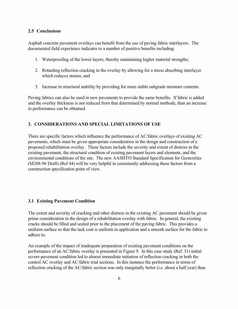
3.1 Existing Pavement Condition The extent and severity of cracking and other distress in the existing AC pavement should be given prime consideration in the design of a rehabilitation overlay with fabric. In general, the existing cracks should be filled and sealed prior to the placement of the paving fabric. This provides a uniform surface so that the tack coat is uniform in application and a smooth surface for the fabric to adhere to. An example of the impact of inadequate preparation of existing pavement conditions on the performance of an AC/fabric overlay is presented in Figure 9. In this case study (Ref. 31) initial severe pavement condition led to almost immediate initiation of reflection cracking in both the control AC overlay and AC/fabric trial sections. In this instance the performance in terms of reflection cracking of the AC/fabric section was only marginally better (i.e. about a half year) than
6
the control AC overlay section. The paving fabric can be expected to bridge over small, thin cracks without the need for crack filling; however severe cracking of significant width (>0.25") and depth must be appropriately addressed during construction of the rehabilitation overlay. Adequate surface preparation procedures are well addressed in paving fabric manufacturers’ literature and should be followed.
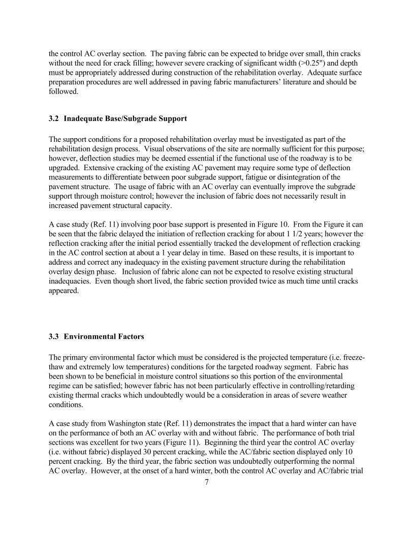
3.2 Inadequate Base/Subgrade Support The support conditions for a proposed rehabilitation overlay must be investigated as part of the rehabilitation design process. Visual observations of the site are normally sufficient for this purpose; however, deflection studies may be deemed essential if the functional use of the roadway is to be upgraded. Extensive cracking of the existing AC pavement may require some type of deflection measurements to differentiate between poor subgrade support, fatigue or disintegration of the pavement structure. The usage of fabric with an AC overlay can eventually improve the subgrade support through moisture control; however the inclusion of fabric does not necessarily result in increased pavement structural capacity. A case study (Ref. 11) involving poor base support is presented in Figure 10. From the Figure it can be seen that the fabric delayed the initiation of reflection cracking for about 1 1/2 years; however the reflection cracking after the initial period essentially tracked the development of reflection cracking in the AC control section at about a 1 year delay in time. Based on these results, it is important to address and correct any inadequacy in the existing pavement structure during the rehabilitation overlay design phase. Inclusion of fabric alone can not be expected to resolve existing structural inadequacies. Even though short lived, the fabric section provided twice as much time until cracks appeared.
3.3 Environmental Factors The primary environmental factor which must be considered is the projected temperature (i.e. freeze-thaw and extremely low temperatures) conditions for the targeted roadway segment. Fabric has been shown to be beneficial in moisture control situations so this portion of the environmental regime can be satisfied; however fabric has not been particularly effective in controlling/retarding existing thermal cracks which undoubtedly would be a consideration in areas of severe weather conditions. A case study from Washington state (Ref. 11) demonstrates the impact that a hard winter can have on the performance of both an AC overlay with and without fabric. The performance of both trial sections was excellent for two years (Figure 11). Beginning the third year the control AC overlay (i.e. without fabric) displayed 30 percent cracking, while the AC/fabric section displayed only 10 percent cracking. By the third year, the fabric section was undoubtedly outperforming the normal AC overlay. However, at the onset of a hard winter, both the control AC overlay and AC/fabric trial
7
sections developed 90 percent cracking. This shows the retardation effects of the fabric for thermal cracks, but only before a severe winter. The inclusion of fabric in the overlay section could not overcome the impact of the extreme weather conditions. However, the waterproofing effects can still have a long term beneficial impact in areas of increased moisture. The decision to utilize fabric in a rehabilitation overlay would have to consider remediation of existing thermal cracking, as well as selection of an AC thickness appropriate for the weather (thermal) conditions. The inclusion of fabric alone should not be expected to remediate thermal cracking.
4. DEVELOPMENT OF PAVEMENT DESIGN MODEL The fundamental concept of the role of a paving fabric in an AC rehabilitation overlay was investigated and is now better understood in order to develop an appropriate design approach for AC/fabric overlays. Specifically, the influence of the paving fabric on the performance and fatigue resistance of a composite AC/fabric overlay has been investigated in a number of laboratory and theoretical studies. Analogous to the glue-laminated wooden beam concept, the fabric in an AC overlay provides a lower elastic modulus than either the underlying existing pavement or the overlying AC overlay and acts as a stress relief layer with reduced interlayer adhesion (Ref. 32). The inclusion of a paving fabric in an AC overlay also improves the resistance to reflection cracking (Refs. 32, 34, 40), as well as increases fatigue life (Refs. 33, 37, 39) and performance life (Refs. 34, 35, 38). Because of these attributes, an equivalent AC thickness for the paving fabric of 1.3" may be appropriate (Ref. 31). This equivalency factor compares favorably with the 0.1' to 0.15' recommended by California (Ref. 12). A total design concept related to paving fabric application in AC rehabilitation of existing AC pavements should consider not only the improved fatigue life, but also improved subgrade support afforded through the maintenance of a uniform subgrade moisture regime.
4.1 Research Approach Technique for Pavement Design Utilizing Paving Fabric One of the principal requirements of this research effort was the development of technically based justification for the use of paving fabric in pavement overlay design. In order to assure broad based acceptance, use and application of the method, the AASHTO flexible pavement structural design procedure, supplemented by elastic layer theory analytical techniques was used in the development of recommendations. This approach considers the fundamental impact of vehicular loading, pavement structure, and the influence of environmental effects on pavement roughness development (or increased serviceability losses)on the layers of the pavement overlay. The final procedure incorporates the benefits of paving fabrics (Figure 12) in AC overlay rehabilitation and considers of environmental factors (Figure 13), as well as pavement structural conditions (Figure 14). The benefits of paving fabrics were estimated based on two different models.
8
1. The Structural Design Model - Accounts for the equivalent thickness contribution of paving fabrics. Sections with and without fabric are modeled to provide an equal performance (fatigue life).
2. The Environmental Design Model - Accounts for the equivalent thickness contribution of paving
fabrics. Sections with and without fabric are modeled to provide an equal serviceability - performance life (number of 18 kip ESAL to deteriorate from Initial Present Serviceability Index to Terminal Present Serviceability Index).
Sketches 1 and 2 illustrate these overall models and the values used. Structural Design Model Although the paving fabric interlayer is not a structural strength layer, there are pavement structural benefits as defined in this section. The structural design model for paving fabric application (Figures 14 and 15) uses the AASHTO load criteria of eighteen kips single axle loads (18 kip ESALs) and is based on keeping the same load induced tensile strain value at the bottom of the existing AC layer of a composite AC-fabric overlay alternative as estimated in a basic AC overlay (without fabric). In this instance, the tensile strain in the bottom of an existing AC layer of a conventional overlay exposed to the existing moisture content and support regime will be equal to the tensile strain in the existing AC layer with an AC-fabric overlay of a thinner structure because of improvement in the moisture and support conditions. In this approach, the conventional AC overlay option would be calculated by an agency using their normal accepted overlay design method. The equivalent AC-fabric thickness would then be established using the conventional overlay design thickness and relevant design criteria and parameters for the existing site conditions. Environmental Design Model The environmental design module for paving fabric applications in AC overlays is based on the AASHTO pavement design serviceability concept, as a function of road roughness (i.e. slope variance), because of the major impact of a number of environmental parameters (Figure 13). The other parameters involved in the AASHTO flexible pavement serviceability concept i.e., cracking and patching, as well as rutting, are principally load induced phenomenon and are believed to be addressed in the structural design model. The installation of a paving fabric reduces the infiltration of surface water and maintains the moisture contents at or near existing levels. This combination of benefits offers significant control of the subsequent amount of soil swell, shrinkage and heave and, by inference, the amount of road roughness (i.e. slope variance). The basic approach used in this module consists of the definition of equivalent designs with reduction in the required AC overlay thickness with the addition of a paving fabric. The AASHTO DNPS86 computer program was used to calculate the number of 18 kip Equivalent Single Axle Loads (ESALs) which would reduce the serviceability of an improved pavement section from an initial level of 4.5 to a terminal level of 2.5 for an AC overlay. The swelling soil and
9
heaving options within DNPS86 were utilized to represent the interactive effects of soil class (fine or coarse grained soils), moisture conditions (wet or dry) and temperature regimes (freeze or non freeze) for particular targeted pavement conditions. Design Factors Important to Both Models The factors selected for the AC overlay analysis (Figures 13 and 14) include general moisture classification (wet or dry region), temperature or climatic designation (freeze or non freeze zones), subgrade type (fine, mixed or coarse grained soils), subgrade support characteristics (resilient modulus), geological formations (depth to underlying rigid layer), existing pavement structure (existing AC thickness), as well as the proposed pavement improvements (overlay thickness) for the proposed project site. The moisture (wet or dry region) and temperature (freeze or non freeze zones) parameters are considered essential because of the expected impact of the subgrade resilient modulus on the soil swelling and frost heave models. The subgrade type or class, subgrade modulus and depth to rigid layer are geologic features which are also identified with specific site conditions. A 6" granular base layer with a resilient modulus of 25,000 psi for moist conditions was used in the development of the environmental design module. Nominal modulus values of 2,500 to 10,000 psi were assigned for subgrade soils to cover the range of values expected in the field. This corresponds to fine grained soils OH, CH, MH, OL, CL, and ML, and the sand and sandy soils SC, SM, SU, SP and SW. The expected improvement in granular base and subgrade support due to long term benefits of paving fabric installation is reflected in substantial (i.e. 100 percent) increases in the resilient moduli of the base and subgrade layers. This level of modulus increase conforms with field results (see literature research section), as well as AASHTO road test results shown in Table 5. From this AASHTO Design Guide Table it can be seen that the resilient modulus of a granular base material for a stress state of 5 psi can be increased from 8400 psi in a wet condition to 10,500 psi (1.25 times greater ) in a damp state, and to 21,000 psi (2.5 times greater) in a dry state. A doubling of the base and subgrade resilient modulus values subsequently achieved as a direct result of the installation of a paving fabric seems a reasonable assumption, based on field results (Ref. 42 and 43). The AASHTO table (Ref. 43), reproduced as Table 6, was used to define the AASHTO moisture coefficients for this study. With the installation of a paving fabric it was conservatively assumed that the drainage coefficient was generally increased by one level of drainage quality no matter what percent time exposure to saturation (i.e. wet, median and dry environmental conditions). This is because preventing the surface water from infiltrating through the pavement is potentially a more efficient was to decrease the detrimental effects of moisture that even good drainage. The subgrade classes or types of fine grained, mixed and coarse grained soils were established to represent the principal types of soils. Fine grained soils or high plasticity (CH) clays are considered strictly cohesive soils which derive load support and modulus characteristics from the soil cohesion alone. These soils are expected to display uniform modulus values with depth and are relatively unaffected by any overburden pressures (i.e. soils maintain a uniform modulus regardless of depth). On the other hand the coarse grained (gravely) or granular (sandy) soils are considered strictly non cohesive soils which derive load support and modulus characteristics from friction between soil
10
particles and are directly affected by overburden pressure, i.e. modulus increases with depth below ground surface. The mixed soil classification defines the condition in which the soil displays both cohesive and frictional characteristics and represents a soil that is also affected by overburden pressure, generally to a lesser extent than a coarse grained or granular soil. The subgrade support characteristics were developed using layered theory. Layered elastic theory was used to develop a relationship between a representative subgrade modulus and a nominal subgrade (i.e. laboratory developed) modulus estimate (Table 7). These algorithms presented in Table 7 were used in the development of both the structural and environmental design models. The representative subgrade modulus estimate provides a measure of the combined resultant effects of the subgrade modulus value, subgrade class, and proximity of an underlying rigid layer on the overall pavement response to vehicular loading, while the 'nominal' subgrade modulus is considered to be that estimate acquired through resilient modulus testing of a subgrade soil sample in the laboratory. The representative modulus should be similar to a modulus acquired through insitu nondestructive pavement testing with a falling weight deflectometer (FWD). The depth to rigid layer is also an important factor because of an impact on the deflection response of the total pavement structure (including all underlying soil layers) to vehicular loads. At greater depths (20' or greater) to an actual or assumed rigid layer, the presence of the rigid layer has a lesser influence on pavement deflections under load and would be indicative of a modulus similar to a laboratory produced or 'nominal' subgrade modulus estimate. Figures 16a and 16b show these effects from predictions made using the AASHTO Design procedure models (Ref 42). On the other hand at shallow depths (10' or less) the presence of a rigid layer beneath an established soil (e.g. subgrade soil with a modulus of 5,000 psi) would result in significantly lower pavement deflections in response to applied loads (Figure 16a). In a comparison of the results in Figures 16a and 16b it can be seen that the deflection basin for a 5,000 psi soil with a shallow depth to rigid layer (e.g. 2.5') would essentially match the deflection basin of a 19,000 psi soil with a 30' depth to rigid layer. If a rigid layer exists but the depth to rigid layer is not considered , then the deflection basin could be indicative of a higher 'representative' modulus (Figure 16b). A range in depth between 5 and 30 feet was defined for this investigation because at these depths the elastic layered theory model predicted deflections are most significantly affected. Figure 17 shows the impact of this variable on the tensile strains at the bottom of the existing asphalt layer. The existing pavement structure at a particular site forms a critical part of any assessment of the various pavement improvement alternatives. The existing pavement structural section, particularly the asphalt concrete portion, should be established before an overlay design analysis is instituted. For this effort the range in existing total asphalt thickness (i.e. wearing course, binder and base layers) was established as 2 to 6 inches to represent designs related to both low and high traffic volumes. The existing pavement structure was modeled as a composite AC layer (i.e. including all contiguous AC surface, binder and base layers), supported on a 6" granular base, resting on the subgrade soil. The existing AC layer was characterized by a two layer configuration. The principal part AC layer was assigned a resilient modulus of 500,000 psi. The top 0.25" of the existing AC layer was assumed to be highly oxidized/aged and was therefore assessed a resilient modulus of 750,000 psi.
11
The proposed AC overlay thickness for the two overlay options are essentially represented in Figures 14 and 15. The conventional AC overlay option is defined as a new AC layer placed directly on either the existing AC surface layer or on any required leveling course or patching. The range in thickness of proposed AC overlay is defined as 2 to 5 inches. The AC-fabric overlay option consists of the placement of a paving fabric either directly on the existing AC surface layer or on a limited thickness of AC leveling course, followed by the placement of a new AC overlay thickness. The fabric layer was assumed to be a part of the pavement overlay structure and was assigned a thickness of 0.15" and a modulus of 5,000 psi. In either paving fabric installation alternative the AC overlay thickness is considered to extend from the bottom of the paving fabric to the top of the new AC overlay layer.
4.2 Structural Design Model and Applications Algorithm Development Elastic layered system solutions for various factors and parameters were used to develop mathematical algorithms (Tables 8 and 9) relating the equivalent AC-fabric overlay thickness. to a conventional AC overlay thickness. The analytical approach used a statistical fractional factorial design to allow consideration of all two way interactions or cross products and specific three way interactions. Analysis of variance and sensitivity analysis were used as aids in defining main effects (original and overlay thickness), two way interactions (original thickness times overlay thickness) and quadratic or squared (depth to rigid layer) terms. Of all the factors and parameters considered the key effects are overlay thickness (Tol), original asphalt pavement thickness (Torig), depth to rigid layer (DRL) and resilient modulus of the subgrade (Esg). Those factors and interactions producing the greatest impact on the equivalent thickness (see sensitivity analysis in Tables 8 and 9) were then identified as key factors in the development of mathematical algorithms utilizing regression analysis techniques. Both arithmetic (Table 8) and logarithmic (Table 9) equivalent thickness algorithms were developed. The results of the two algorithms were averaged to define a specific equivalent AC-fabric overlay thickness. The final combined AC-fabric overlay thickness would then be the proposed conventional overlay thickness minus the equivalent thickness. The equivalent AC-fabric thickness value essentially represents the reduction in AC thickness allowed with the installation of a paving fabric. A minimum AC-fabric overlay pavement structure of 1.5” was used in the analysis based on the review of field results. Application of Algorithms The two AC-fabric equivalent thickness algorithms were used to develop design nomographs for two important geotechnical cases. The first case (Figure 18) defines the relationship between the equivalent AC-fabric overlay thickness and combinations of existing AC thickness and proposed conventional AC overlay thickness for a relatively strong soil support (resilient modulus of 15,000
12
psi) condition and little influence of an actual or perceived underlying rigid layer (i.e. depth to rigid layer of 30'). The second case (Figure 19) displays the relationship between the equivalent AC-fabric overlay thickness and combinations of existing AC thickness and proposed conventional AC overlay thickness for weak soil support (resilient modulus of 5,000 psi) condition and strong influence by an actual underlying rigid layer (i.e. depth to rigid layer of 5'). The first nomograph (Figure 18) would represent a pavement located in a relatively dry (i.e. drier soil condition) plains area (no rock outcroppings), while the second nomograph (Figure 19) would represent a pavement section located in a wet (i.e. low soil modulus), mountainous (shallow depth to rigid layer) area. For a dry, plains area (Figure 18), the AC-fabric equivalent overlay thickness values range from 0.5" to 1.75", respectively for a thin (i.e. 2") and thick (i.e. 4.5") proposed AC overlays of a thin existing AC pavement (i.e. 2") thickness. On the other hand the AC-fabric equivalent thickness values cover a minimal 0.6 to 0.9" range for the thicker original AC pavements (i.e. 6"). It should be noted that the 1.75” value compares well with the 0.15' ( or 1.8") guideline for AC -fabric replacement thickness advocated by the State of California. From this nomograph it is obvious that the impact of the paving fabric is greater for the thinner existing AC pavements (i.e. 4" or less). In fact the range in equivalent AC-fabric overlay thickness increases with the thinner existing AC pavements. This observation generally conforms with statements found in the literature concerning the benefits of installing paving fabric in existing thicker AC pavements. For the conditions presented in Figure 18 a minimum proposed conventional thickness of 2.5" (with a equivalent thickness of 0.5") would be required. For a wet, mountainous area (Figure 19), the AC-fabric equivalent overlay thickness values range from 0.5" to 1.38", respectively for a thin (i.e 2") and thick (i.e. 4.5") proposed AC overlay of a thin existing AC pavement (i.e. 2") thickness. On the other hand the AC-fabric equivalent thickness value is only 0.5" for the thicker original AC pavements (i.e. 6"). From this nomograph, it is also obvious that the impact the paving fabric is greater for the thinner existing AC pavements (i.e. 4" or less) and that the range in equivalent AC-fabric overlay thickness increases with the thinner existing AC pavements. As observed in the previous case (discussion above) a minimum proposed conventional thickness of 2.5" (with a equivalent thickness of 0.5") would be required in this type region. Examples of total AC-fabric structural thickness requirements for various existing and proposed AC thickness for dry plains and wet mountainous areas are presented in Table 10. The equivalent AC-fabric thickness can be established for known values of the original AC layer thickness, the depth to rigid layer and subgrade resilient modulus, as well as a defined AC thickness value based on a conventional overlay design procedure. The cost effectiveness of paving fabrication can be easily documented. The installed price of paving fabrics ranges from $0.60 to $1.00 depending on job size and location. Based on hot mix asphalt concrete price of $6.00 per square yard for 4” pavement, 1” overlay costs approximately $1.50. Thus the fabric can replace 1” of overlay and cost approximately half as much.
13
4.3 Environmental Design Module and Applications Algorithm Development The development of mathematical algorithms for an environmental paving fabric equivalent thickness was based on the AASHTO flexible pavement design procedures. The swelling soil and heaving options within DNPS86 were utilized to represent the interactive effects of soil class (fine or coarse grained soils), moisture conditions (wet or dry) and temperature regime (freeze or non freeze) for particular targeted pavement conditions. The representative subgrade modulus estimate provides a measure of the combined resultant effects of the subgrade modulus value, subgrade class, and proximity of an underlying rigid layer on the overall pavement response to vehicular loading. Since the installation of a paving fabric is expected to provide a relatively constant base and subgrade moisture regime, the basic approach used in this development consists of the definition of equivalent environmental designs which include a reduction in the required AC overlay or surface layer thickness related primarily to an expected control of moisture and temperature control in the development of pavement roughness. The environmental equivalent thickness algorithms were also developed utilizing statistical experimental design approaches involving the factors and parameters of general moisture classification (wet or dry), temperature or climatic designation (freeze or non freeze), subgrade type (fine, mixed or coarse grained soils) and support characteristics (resilient modulus), geological formation (depth to actual or perceived underlying rigid layer), existing pavement structure (existing AC thickness) and proposed pavement improvements (overlay thickness and modulus) for the proposed project site. The analysis of variance, sensitivity analysis and algorithms are presented in Tables 11 and 12, respectively for the arithmetic and logarithm formats. A statistical fractional factorial design was also used to evaluate all main effects, two way interactions or cross products and specific three way interactions. Of the various factors and parameters considered in this analysis the key effects are soil type, general moisture conditions, original pavement thickness, proposed overlay thickness and depth to rigid layer. Those factors and interactions producing the greatest impact on the environmental equivalent thickness (see sensitivity analysis in Tables 11 and 12) were then identified as key factors in the development of mathematical algorithms utilizing regression analysis techniques. Both arithmetic (Table 11) and logarithmic (Table 12) equivalent thickness algorithms were developed. Application of Algorithms The results of the two algorithms were averaged to define a specific equivalent AC-fabric overlay thickness based on environmental conditions. The equivalent environmental AC-fabric thickness value essentially represents the reduction in AC thickness allowed with the installation of a paving fabric. It should be noted here that a minimum AC-fabric overlay pavement structure of 1.5" is recommended based on the review of field results. The combination of proposed conventional AC overlay thickness and replacement of AC thickness with fabric should therefore should yield an overall thickness of 1.5" or more.
14
4.4 Final Combined Model The two AC-fabric equivalent thickness algorithms were used to develop design nomographs for the four basic environmental conditions, i.e. dry non freeze (Figure 20), wet freeze (Figure 21), dry freeze (Figure 22) and wet non freeze (Figure 23). The first nomograph (Figure 20) is representative of a low traffic volume pavement, located in a dry non freeze zone, with a low AC thickness (i.e. 2") and constructed with weak soil support (i.e. subgrade modulus of 5000 psi), while the second nomograph (Figure 21) is representative of a moderate traffic volume pavement section, located in a wet freeze zone, with excellent soil support characteristics (i.e. subgrade modulus of 15,000 psi). The remaining nomographs are also representative of moderate traffic volume pavement sections in dry freeze and wet non freeze environmental zones with good to excellent subgrade support (i.e. 10,000 to 15,000 psi). For the dry freeze zone example (Figure 22) the environmental equivalent thickness is essentially 0.38” to 0.5" regardless of soil type and depth to rigid layer. In the wet freeze zone example (Figure 21), as well as the wet non freeze zone example (Figure 23) the environmental equivalent thickness varies between about a 0.5" at a 30 ft depth to rigid layer to approximately 0.62" at depth to rigid layer of 5 ft. Finally in the example related to a dry freeze environmental zone (Figure 22) the impact of soil type and depth to rigid layer appear to be more dramatic. The equivalent thickness values are lower and range from less than a 0.25" for a granular soil to a 0.5" for a clay soil at a depth to rigid layer of 30 ft, while at a very shallow rigid layer depth (i.e. 5 ft) the equivalent environmental thickness range from 0.38" for a granular soil to 0.62" for a clay soil. In general, the environmental equivalent thickness appear to be about a 0.5" regardless of environmental zone, soil type and depth to rigid layer. It is lower for a significant depth to rigid layer and higher at a shallower depth. In addition the equivalent thickness is generally greater for clay soils than granular soils. In completing an AC-fabric overlay design analysis the conditions and parameters related to the proposed overlay project sites should be used to establish both the structural and environmental equivalent thickness, then the overall AC-fabric overlay thickness is defined by subtracting the sum of the two equivalent thickness values from the proposed conventional AC thickness value. The overall AC-fabric overlay thickness should be a minimum of 1.5".
5. CONSIDERATION OF FABRICS IN A PAVEMENT MANAGEMENT SYSTEM The practical requirements of incorporating paving fabric design in pavement management systems have been addressed and a method/approach has been identified. Since rehabilitation, repair and maintenance are principal elements in pavement management, they will receive the most funding over the next three decades in the United States and elsewhere in the world. As a result, this becomes a very important consideration increasing utilization of paving fabric. In most cases, existing pavement management systems do not recognize design sections with paving fabric as an alternative or option for consideration in the decision tree used by the pavement manager.
15 In this project, a design and analysis approach was developed which will allow the incorporation of
paving fabric alternatives and options in pavement management systems either by quantifying extended performance life periods provided by inclusion of paving fabric or identifying pavement section thicknesses with paving fabric, which exhibit equivalent performance life periods. It is believed that the paving fabric design procedure presently in Chapter 4 can be easily incorporated in existing pavement management systems because of the mathematical form of the algorithms.
5.1 Requirements There are four key steps required to incorporate a paving fabric alternative in a pavement management system. 1. Quantify the existing pavement conditions, 2. Estimate of fabric in-place costs versus traditional hot mix asphalt material costs, 3. Predict the change in performance with fabric as compared to no fabric, and 4. Quantify the amount of hot mix overlay which can be replaced by fabric use Project Level versus Network Level Requirements For these two distinctly different levels of analysis, the pavement management system will require differing degrees of information. At the network level the pavement management system uses the following:
1. Existing pavement conditions • Existing cracking extent and severity • Existing roughness and/or rutting estimates
2. Estimated cost • Average in-place price per square yard
3. Additional pavement life to final condition state • Number of additional years or equivalent single axle wheel loads (ESALs) to the
terminal serviceability level 4. Reduction in surface layer thickness with inclusion of paving fabric. For example, fabric
may be assumed to provide a performance life equivalent to 1.2” of hot mix overlay when used as an interlayer.
At the project level of analysis, the engineer considers a specific pavement section in much more design detail. At this level the designer typically uses a project level design tool such as AASHTO’s DARWIN (Design and Rehabilitation in Windows). At the project level, the following information is necessary.
1. Existing pavement conditions • Average vertical deflection, mils • Average crack movement, mils • Type of cracks and their severity and extent
16
• Existing asphalt surface oxidation and affinity for tack coat • Existing drainage of site
2. Estimated cost • Price estimates from contractors including tack coat and surface preparation
3. Estimated performance • Drainage coefficients for AASHTO design model for lower layers • Estimated moduli values for all layers • Estimated 'representative' subgrade modulus values • Estimated/planned future maintenance and rehabilitation schedules values • Designed overlay thickness for given environmental cycles and traffic loads 18 kip
ESALs • Depth to rigid layer
One decision tree which is used in the Maxim Technologies, Inc. pavement management system is shown in Figure 24. Sections which have extensive rutting and/or significant roughness may not be candidates for fabric use since the pavement may not be stable. Pavements which exhibit thermal cracking and low severity fatigue cracking are candidates for fabric use. Existing Pavement Conditions Existing pavement conditions must be quantified at both the network and project level of pavement evaluation. At the network level the type, severity, and extent of each pavement distress must be quantified. In general, nondestructive testing (NDT) or falling weight deflectometer measurements and materials sampling and testing data are not collected. The roughness of the pavement is often measured or estimated at the network level. This measurement aids in quantifying the serviceability (or measure of rider acceptance) of the pavement (Reference AASHTO Road Test). Rutting, longitudinal roadway distortion of various wavelengths, and surface failures all contribute to a low ride quality. Roughness and surface condition surveys for distress can be used to screen potential candidate sections for consideration of paving fabric use. At the project level, the measurements of surface distress and roughness measurements are supplemented by fundamental structural testing. The NDT testing helps to identify the soundness of the pavement, as well as suitability for an overlay. Crack and joint movements must also be measured or estimated to determine if the pavement is a good candidate for fabric use. Costs The in-place cost of fabric can vary according to job size, surface preparation effort, tack coat rate, fabric type, and contractor equipment and experience. At the time of this report, fabric can generally be placed for $0.60 to $1.00/SY. For direct consideration these costs must be compared with an equivalent amount of hot mix asphalt concrete (HMAC) or surface treatment which would be replaced to achieve the same performance. The determination of the amount of AC is based on
17
performance assumptions discussed in the next section. Pavement Performance Pavement performance estimates with and without fabric must be established. The improved pavement condition; in terms of roughness, cracking, and deflection, after an overlay or surface treatment must be estimated. Pavement management system historical data bases can be used to develop better long term models. Evidence in the literature indicates that fabric will retard the onset of reflection cracks and possibly roughness and deflection by controlling the moisture levels in the lower layers. If a paving fabric is proposed as an addition to the pavement structure, it is this additional life in terms of months or year or additional 18 kip ESALs carried which must be quantified in dollar terms. On the other hand, if the paving fabric is scheduled to replace a portion of the proposed AC or surface treatment layer, then the cost savings for equivalent pavement performance periods must then be established.
5.2 Summary The nomographs and data in Section 4 can be used directly in preparing pavement management system inputs such as required by the design tree selection in Figure 24.
6. CONCLUSIONS As a result of our investigation we found that the inclusion of a nonwoven paving fabric interlayer system significantly improves the performance of AC overlays. As reported by the experts, this performance improvement is a result of both the waterproofing capabilities and the stress absorption capabilities of the paving fabric system. When comparing thinner AC overlays with the nonwoven paving fabric interlayer system to thicker overlays without the system, there was a good consensus among the literature and the interviewed experts. Their conclusion was that the paving fabric system gives additional overlay performance equivalent to increased overlay thickness of 1.0 to 1.8 inches with an average performance equivalency of approximately 1.3 inches. The paving fabric interlayer is not meant to be a structural layer to make up pavement structural thickness deficiencies. Also, this amount of AC overlay equivalency does assume that the existing pavement is stable, the paving fabric system is properly installed, and a minimum overlay thickness of 1.5 inches is placed. However, even at this thickness the inclusion of fabric has been shown to increase service life. In almost all reports where the paving fabric system was shown to be of limited or no benefit, either the covered pavement was too deteriorated or too thin of an overlay was used.
18
7. REFERENCES 1. Lorenz, V.M., "New Mexico Study of Interlayers, Used in Reflective Crack Control,"
Geotechnical Fabrics Report May/June 1987, p. 17. 2. Sutherland, M. and Phillips, P., "Geotextile Reinforced Sprayed Seal Roads in Rural
Australia", Proceedings of the Fourth International Conference on Geotextiles, Geomembranes and Related Products, Vol. 1, Presented in The Hague, Netherlands, A.A. Balkema, Rotterdam, Netherlands, May 1990, pp. 209-212 & 1034-1035.
3. Perfetti, J. and Sangster, T., "The Function of Geotextiles in Pavement Structures", Proceedings of Geosynthetics '89, Vol. 2, San Diego, CA, USA, IFAI, Feb 1989, p. 334-344.
4. Gibb, I., "Chip Sealing in the Shire of Broome Australia," Geosynthetics World, London, UK, February 1992.
5. Fabric Reinforced Chip Seal Surfacing, Hoechst Celanese Brochure, Hoechst. 6. Shatnawi, S.R., "Premature AC Pavement Distress - District 02 Investigation (Interim
Report)," California Department of Transportation, Sacramento, CA, December 1992, FHWA-CA/TL-92-07, 99 pages.
7. Walsh, I.D., "Geotextiles in Highway Surface Dressing", Proceedings of the Third International Conference on Geotextiles, Vol. 1, Vienna, Austria, Apr 1986, pp. 135-140.
8. Walsh, I., "Highway Surface Dressing," Geosynthetics World, London, United Kingdon, May 1990.
9. Hannon, J., Miner, J., and Donahue, M., "AC Overlay Strategies for PCCP Pavement Using Asphalt Saturated Textiles," Proceedings of Geosynthetics '87 (New Orleans, LA USA), Vol. 1, IFAI, St. Paul, MN USA, February 1987, pp. 69-80.
10. Same as 9 above. 11. Ahlrich, R.C., "Evaluation of Asphalt Rubber and Engineering Fabrics as Pavement
Interlayers," Final Report, Miscellaneous Paper GL-86-34, U.S. Army Corps of Engineers, Waterways Experiment Station, Vicksburg, MS, November 1986, 48 pages.
12. Predoehl, N.H., "Evaluation of Paving Fabric Test Installations in California - Final Report," California Department of Transportation, Report No. FHWA/CA/TL-90/02, February 1990.
13. Same as 9 above. 14. McGhee, K.H., "Control of Reflection Cracking in a Fabric-reinforced Overlay on Jointed
Portland Cement Pavement," Virginia Highway & Transportation Research Council, Charlottesville, VA, VHTRC 83-R8, August 1982.
15. Barry, Gerald F., "Geotextile Repairs Deteriorating Four-Lane Highway," Geotechnical Fabrics Report, IFAI, St. Paul, MN, November 1988, p. 18.
16. Knight, N.E., Heavy duty membranes for the reduction of reflective cracking in bituminous concrete overlays. Research Project 79-6, Final Report, August 1985, Pennsylvania DOT.
17. Button, J.W., "Overlay Construction and Performance Using Geotextiles," Transportation Research Board Annual Meeting, Washington, DC, January 1989, 35 pages.
18. Maurer, Dean A. & Malasheskie, Gerald J. (USA), "Field Performance of Fabrics and Fibers to Retard Reflective Cracking."
19. Same as 9 above. 20. Barnhart, V.T., "Field Evaluation of Experimental Fabrics to Prevent Reflective Cracking In
19
Bituminous Resurfacing - Final Report," Research Project 80 NM-617, Research Report No. R-1300, Research Laboratory Section, Materials and Technology Div., Michigan Transportation Commission, Lansing, MI, July 1989, 22 pages.
21. Same as 9 above. 22. Same as 9 above. 23. Karam, G., “Experience of DuPont De Nemours in Reflective Cracking: Site Follow Up,”
Reflective Cracking in Pavements, Austria. 24. Herbst, G., “Asphalt Overlay on Cracked-Sealed Concrete Pavement,” Reflective Cracking
in Pavements, Austria. 25. Hugo, F., Strauss, P., and Schnitter, O., "The Control of Reflection Cracking with the Use of
a Geotextile. A Ten Year Case History", Proceedings of the Second International Conference on Geotextiles(Las Vegas, NV USA), Vol. 2, IFAI, St. Paul, MN USA, August 1982, pp. 517-522.
26. "Report on Performance of Fabrics in Asphalt Overlays", FHWA , Office of Highway Operation, Experimental Application and Evaluation Branch, September 1982, 39 pp.
27. Petromat Controls Reflective Cracking, Paving Information Bulletin, Petromat. 28. Hanson, M.A.; Paulson, R., "Reinforcement Objective: Residential Street Resurfacing,"
Geotechnical Fabrics Report," IFAI, St. Paul, MN USA, July/August 1985, p. 9. 29. Pourkhosrow, G., "The Evaluation of Non-woven Fabrics: Petromat and Mirafi," Oklahoma
Department of Transportation, Final Report, FHWA/OK 82(6), May 1982, 25 pages. 30. Interim Status Report, Paving Information Bulletin . 31. Lorenz, V.M., "New Mexico Study of Interlayers, Used in Reflective Crack Control,"
Geotechnical Fabrics Report May/June 1987, p. 17. 32. Grzybowska,W., Wojtowicz, J., and Fonkerko, L., “Application of Geo-Synthetics to
Overlays in Cracow Region of Poland.” 33. Livnell, M., “Bituminous Precoated Geotextile for Retarding Reflection Cracks,” Reflective
Cracking in Pavements, Austria. 34. Button, J.W., Epps, J.A., Lytton, R.L., and Harmon, W.S., "Fabric Interlayer for Pavement
Overlays", Proceedings of the Second International Conference on Geotextiles (Las Vegas USA), Vol. 2, IFAI, St. Paul, MN, Aug 1982, pp. 523-528.
35. Yandel, W.O. and Curiskis, J.I., "Fabric Reinforcement to Extend Pavement Life," Asphalt Paving Technology 1983, Proceedings, Association of Asphalt Paving Technologists, February, March 1983, Volume 52, p.585-600.
36. Petit, C., Caperaa, S. and Michaut, J-p., Influence of Modulus Ratio on Crack Propagation in Multilayered Pavements, @ Reflective Cracking in Pavements, Assessment and Control, Proceedings of a conference held in LiPge, Belgium, Chapman and Hall, London, United Kingdom, March 1993, pp. 220-227.
37. Smith, R.D., "Laboratory Testing of Fabric Interlayers for Asphalt Concrete Paving", California Department of Transportation, 1984.
38. Phillips, P., “Long Term Performance of Geotextile Reinforced Seals,” Reflective Cracking in Pavements, Austria.
39. Zhongyin Guo, “Prevention of Cracking Progress of Asphalt Overlay,” Reflective Cracking Pavements, Austria.
40. Murray, C.D., "Simulation Testing of Geotextile Membranes for Reflection Cracking", Proceedings of the Second International Conference on Geotextiles, Vol. 2, Las Vegas, NV,
20
USA. Aug 1982, pp. 511-516. 41. Majidzadeh, K., Luther, M.S., and Skylut, H., "A Mechanistic Design Procedure for Fabric-
Reinforced Pavement Systems", Proceedings of the Second International Conference on Geotextiles, Vol. 2, Las Vegas, NV, USA, Aug 1982, pp. 529-534.
42. Table 2.4, Recommended mi Values for Modifying Structural Layer Coefficients of Untreated Base and Subbase Materials in Flexible Pavements Section, Section 2.3.5 Layer Coefficients, pp. II-25, 1993 AASHTO Guide for Design of Pavement Structures, American Association of State Highway and Transportation Officials, Washington, DC.
43. Section 2.3.5 Layer Coefficients, pp. II-20, 1993 AASHTO Guide for Design of Pavement Structures, American Association of State Highway and Transportation Officials, Washington, DC.
21