Embed Size (px)
Citation preview
NORMEINTERNATIONALEINTERNATIONALSTANDARD
CEIIEC
60895Deuxieme edition
Second edition2002-08
Travaux sous tension -Vetements conducteurs pour usage jusqu'a 800 kVde tension nominate en courant alternatif et ±600 kVen courant continu
Live working -Conductive clothing for use at nominal voltageup to 800 kV a.c. and ±600 kV d.c.
© IEC 2002 Droits de reproduction reserves -- Copyright - all rights reserved
Aucune partie de cette publication ne peut etre reproduce niutilisee sous quelque forme que ce soil et par aucun precede,electronique ou mecanique, у compris la photocopie et lesmicrofilms, sans I'accord ecrit de I'editeur.
No part of this publication may be reproduced or utilized in anyform or by any means, electronic or mechanical, includingphotocopying and microfilm, without permission in writing fromthe publisher.
International Electrotechnical Commission, 3, rue de Varembe, PO Box 131, CH-1211 Geneva 20, SwitzerlandTelephone:+41 2291902 11 Telefax:+41 22 919 03 00 E-mail: [email protected] Web: www.iec.ch
Commission Electrotechnique InternationaleInternational Electrotechnical CommissionМеждународная Электротехническая Комиссия
C O D E P R I XP R I C E C O D E
Pourprix. voir catalogue envigueur For price, see currentcatalogue
w
60895 © IEC:2002 - 3 -
CONTENTS
FOREWORD............................................................................................................................... 9INTRODUCTION........................................................................................................................ 13
1 Scope .................................................................................................................................. 152 Normative references.......................................................................................................... 153 Terms and definitions ......................................................................................................... 174 Technical requirements....................................................................................................... 19
4.1 General ...................................................................................................................... 194.2 Technical requirements for conductive material........................................................ 19
4.2.1 Flame retardancy.......................................................................................... 194.2.2 Electrical resistance...................................................................................... 194.2.3 Current-carrying capability............................................................................ 214.2.4 Shielding and screening efficiencies............................................................ 214.2.5 Requirements to withstand cleaning ............................................................. 214.2.6 Spark-discharge protection............................................................................21
4.3 Specific requirements for component parts................................................................214.3.1 Conductive gloves, overshoe socks and socks..............................................214.3.2 Conductive footwear......................................................................................214.3.3 Conductive head cover and face screen........................................................21
4.4 Marking .......................................................................................................................234.5 Packaging ...................................................................................................................234.6 Manufacturer's instructions ........................................................................................23
5 Type tests of conductive material (specimen)......................................................................235.1 Flame-retardancy test................................................................................................23
5.1.1 Principle of test..............................................................................................235.1.2 Test apparatus...............................................................................................235.1.3 Test specimens .............................................................................................255.1.4 Test procedure ..............................................................................................275.1.5 Results...........................................................................................................29
5.2 Electrical resistance test ............................................................................................295.2.1 Test equipment.............................................................................................. 295.2.2 Preparation of test specimens ....................................................................... 315.2.3 Procedure ...................................................................................................... 315.2.4 Test results.................................................................................................... 31
5.3 Current-carrying capability......................................................................................... 335.3.1 Test equipment.............................................................................................. 335.3.2 Preparation of test specimens....................................................................... 335.3.3 Procedure...................................................................................................... 335.3.4 Test results.................................................................................................... 33
5.4 Shielding efficiency.................................................................................................... 335.4.1 Test equipment ............................................................................................. 335.4.2 Test mounting ............................................................................................... 335.4.3 Earth connection ........................................................................................... 355.4.4 Line connection ............................................................................................. 355.4.5 Test procedure .............................................................................................. 35
60895 © IEC:2002 - 5 -
5.5 Resistance to cleaning............................................................................................... 355.5.1 Laundering .................................................................................................... 355.5.2 Dry-cleaning .................................................................................................. 375.5.3 Acceptability of material.................................................................................39
6 Type tests of garment......................................................................................................... 396.1 General.......................................................................................................................396.2 Electrical resistance ...................................................................................................39
6.2.1 Test procedure...............................................................................................396.2.2 Measurement locations..................................................................................416.2.3 Acceptable values..........................................................................................41
7 Type tests of the complete clothing .....................................................................................417.1 Bonding test ...............................................................................................................417.2 Efficiency of conductive clothing ...............................................................................41
8 Type test of the component parts ........................................................................................438.1 Conductive gloves and mitts......................................................................................438.2 Conductive overshoe socks and normal socks...........................................................438.3 Conductive footwear ..................................................................................................438.4 Conductive head cover and face screen ...................................................................45
9 Routine tests ........................................................................................................................459.1 Parts of conductive clothing from a single manufacturer ..........................................459.2 Parts of conductive clothing from multiple manufacturers .........................................45
10 Acceptance checks and tests ..............................................................................................4511 Modification..........................................................................................................................47
Annex A (normative) Suitable for live working (double triangle) (IEC-60417-5216) ................63Annex В (normative) Classification of tests ............................................................................. 65
B.1 Tests on conductive material..................................................................................... 65B.2 Tests on the conductive garment............................................................................... 65B.3 Tests on the conductive component parts ................................................................. 65B.4 Tests on the complete clothing ................................................................................. 67
Annex С (normative) Sampling procedure ............................................................................... 69C.1 General ...................................................................................................................... 69C.2 Classification of defects............................................................................................. 69C.3 General sampling plan............................................................................................... 69C.4 Procedure when testing is carried out in a laboratory
other than the manufacturer's ................................................................................... 69Annex D (informative) Electrodes for determining electrical resistance propertiesof material specimen and garments........................................................................................... 71
D.1 General.......................................................................................................................71D.2 Conductive paint ........................................................................................................71
Annex E (informative) Recommendations for the in-service care, maintenance andperiodic testing of conductive clothing and component parts.....................................................73
E.1 Care, storage and repair ............................................................................................73E.2 Inspection before use ................................................................................................75E.3 Non-destructive periodic testing.................................................................................75
Bibliography ...............................................................................................................................79
60895©IEC:2002 - 7 -
Figure1 -Example ofgeneralarrangementofcompleteconductiveclothing(seeclause3) ............................................................................................................................................... 47Figure2 -Flame-retardancytest -Testchamber (see5.1) ............................................................................................................................................ 49Flame-retardancytest -Specimenholderandsupport (see5.1) ............................................................................................................................................ 5160895©IEC:2002
60895 © IEC:2002 - 7 -
Figure 1 - Example of general arrangement of complete conductive clothing(see clause 3)……………………………………………………………………………………………..47Figure 2 – Flame-retardancy test - Test chamber (see 5.1)………………………………………49Figure 3 – Flame-retardancy test - Specimen holder and support (see 5.1)……………………51Figure 4 - Electrical resistance test - Test set-up (see 5.2.3)...................................................53Figure 5 - Orientation of test specimens for electrical resistanceand current-carrying capability tests (see 5.2.2)........................................................................53Figure 6 - Electrical resistance test - Electrical circuit (see 5.2.3) ...........................................53Figure 7 - Shielding efficiency (see 5.4) ....................................................................................55Figure 8 - Efficiency of conductive clothing (see 7.2)................................................................57Figure 9 - Electrical resistance test - Conductive gloves and mitts (see 8.1) ..........................59Figure 10 - Electrical resistance test - Conductive overshoe socksand normal socks (see 8.2)........................................................................................................59Figure 11 - Electrical resistance test - Conductive footwear (see 8.3) ....................................61
Table B.1 - List of tests to be carried out on the conductive material .......................................65Table B.2 - List of tests to be carried out on the conductive garment .......................................65Table B.3 - List of tests to be carried out on the component parts............................................67Table B.4 - List of tests to be carried out on the complete clothing ..........................................67Table C.1 -Sampling plan (AQL 10) .........................................................................................69
608995 60895 © IEC:2002 - 9 -
LIVE WORKING -CONDUCTIVE CLOTHING FOR USE AT NOMINAL VOLTAGE
UP TO 800 kV AC AND ±600 kV DCч
FOREWORD1) The IEC (International Electrotechnical Commission) is a worldwide organization for standardization comprising
all national electrotechnical committees (IEC National Committees). The object of the IEC is to promoteinternational co-operation on all questions concerning standardization in the electrical and electronic fields. Tothis end and in addition to other activities, the IEC publishes International Standards. Their preparation isentrusted to technical committees; any IEC National Committee interested in the subject dealt with mayparticipate in this preparatory work. International, governmental and non-governmental organizations liaisingwith the IEC also participate in this preparation. The IEC collaborates closely with the InternationalOrganization for Standardization (ISO) in accordance with conditions determined by agreement between thetwo organizations.
2) The formal decisions or agreements of the IEC on technical matters express, as nearly as possible, aninternational consensus of opinion on the relevant subjects since each technical committee has representationfrom all interested National Committees.
3) The documents produced have the form of recommendations for international use and are published in the formof standards, technical specif ications, technical reports or guides and they are accepted by the NationalCommittees in that sense.
4) In order to promote international unification, IEC National Committees undertake to apply IEC InternationalStandards transparently to the maximum extent possible in their national and regional standards. Anydivergence between the IEC Standard and the corresponding national or regional standard shall be clearlyindicated in the latter.
5) The IEC provides no marking procedure to indicate its approval and cannot be rendered responsible for anyequipment declared to be in conformity with one of its standards.
6) Attention is drawn to the possibility that some of the elements of this International Standard may be the subjectof patent rights. The IEC shall not be held responsible for identifying any or all such patent rights.
International Standard IEC 60895 has been prepared by IEC technical committee 78: Liveworking.
This second edition cancels and replaces the first edition, published in 1987 and constitutes atechnical revision of several sections:
- the scope has been extended to cover the use of conductive clothing to ±600 kV d.c.;- revision of the electrical resistance requirements of the fabrics used in conductive
clothing;
- revision of the testing procedures for complete clothing.
The text of this standard is based on the following documents:
FDIS Report on voting
78/469/FDIS 78/478/RVD
Full information on the voting for the approval of this standard can be found in the report onvoting indicated in the above table.
This publication has been drafted in accordance with the ISO/IEC Directives, Part 3.

60895 © IEC:2002 - 11 -
The committee has decided that the contents of this publication will remain unchangeduntil 2007. At this date, the publication will be
• reconfirmed;
• withdrawn; • replaced by a revised edition, or
• amended.
The contents of the corrigendum of February 2003 have been included in this copy.
60895 © IEC:2002 - 1 3 -
INTRODUCTION
This International Standard provides specifications for protective conductive clothing currentlybeing used without incident in live work by qualified electrical workers throughout the world.The adequacy of this clothing is established by its screening efficiency and the electricalresistance of material and component parts of the conductive clothing. Based on resistance measurements carried out by manufacturers and utilities of used clothing being successfullyworn in the field, differences of up to 1 000 fold have been reported.
Verification tests have shown that the clothing is equally effective against the electric fieldexisting in the vicinity of installations up to 800 kV a.c. and ±600 kV d.c.
This standard has been prepared according to the requirements of IEC 61477, whereapplicable.
60895 © IEC:2002 - 1 5 -
LIVE WORKING -CONDUCTIVE CLOTHING FOR USE AT NOMINAL VOLTAGE
UP TO 800 kV AC AND ±600 kV DC1 Scope
This International Standard is applicable to conductive clothing, either assembled fromcomponent parts or forming a single complete clothing, worn by (electrically) skilled personsduring live working (especially bare-hand working) at a nominal power system voltage up toSOOkVa.c. and±600kVd.c.
It is applicable to conductive jackets, trousers, coveralls (one-piece clothing), gloves or mitts,hoods, shoes, overshoe socks and socks.
2 Normative references
The following referenced documents are indispensable for the application of this document.For dated references, only the edition cited applies. For undated references, the latest editionof the referenced document (including any amendments) applies.
IEC 60050-151:2001, International Electrotechnical Vocabulary (IEV) - Part 151: Electrical andmagnetic devices
IEC 60050-651:1999, International Electrotechnical Vocabulary (IEV) - Part 651: Live working
IEC 60050-826:1982, International Electrotechnical Vocabulary (IEV) - Chapter 826: Elect-rical installations of buildings
I EC 60212:1971, Standard conditions for use prior to and during the testing of solid electricalinsulating materials
IEC 60417 (all parts), Graphical symbols for use on equipment
IEC 60456:1998, Clothes washing machines for household use - Methods for measuring theperformance
IEC 60743:2001, Live working- Terminology for tools, equipment and devices
IEC 61318/TR2:1994, Live working - Guidelines for quality assurance plans
IEC 61477:2001, Live working - Minimum requirements for the utilization of tools, devices andequipment
ISO 2859-1:1999, Sampling procedures for inspection by attributes - Part 1: Samplingschemes indexed by acceptance quality limit (AQL) for lot-by-lot inspection
ISO 3175:(all parts), Textiles - Professional textile cleaning and finishing
ISO 3290:2001, Rolling bearings - Balls - Dimensions and tolerances
60895 © IEC:2002 - 1 7 -
ISO 6330:2000, Textiles - Domestic washing and drying procedures for textile testing
ISO 9000:2000, Quality management systems - Fundamentals and vocabulary ISO
9001:2000, Quality management systems - Requirements
ISO 9004:2000, Quality management systems - Guidelines for performance improvements
3 Terms and definitions
For the purposes of this International Standard, the following definitions apply.
NOTE Further information on terminology is illustrated in figure 1.
3.1conductive clothingclothing made of natural or synthetic material with integral interwoven conductive fibres, orlayers, used to provide electrical continuity between all parts of the clothing and a reduction ofelectric field[IEC 60743, definition 8.2.7, modified]
3.2conductive materialmaterial composed of metallic threads or non-metallic conductive substances and natural orsynthetic threads closely woven, knitted, or layered
3.3equipotential bonding lead (bonding lead)flexible metallic connection used by the worker to connect or disconnect his or her conductiveclothing, bucket or screen, to or from another conductive part to create equipotential bondingNOTE 1 This lead is not an earthing device.NOTE 2 The means of securing or connecting the lead shall be such that under emergency conditions, forexample, a fall, the lead can separate.
[IEV 651-07-07, modified]
3.4head cover (hood)part of the clothing, either as a separate item or integrated into a complete garment, thatcovers the head
3.5face screen for electrical worksprotective device made of conductive, solid, or meshed materialNOTE It provides electrical continuity with the conductive clothing of the worker and a reduction of electric field tothe face, or part thereof
[IEC 60743, definition 8.4.3]
3.6conductive overshoe socksock made of conductive material and worn over shoe/boot
3.7 garmentmain body of the clothing consisting of jacket and trousers
60895 © IEC:2002 - 1 9 -
3.8component partsadditional elements of the complete clothing such as gloves, socks, head protection, andfootwear worn in addition to the main garment and bounded to it
3'9.shielding efficiencybase log 10 of the ratio of a voltage without the conductive clothing to the voltage measuredat the spot with conductive clothing
3.10screening efficiencyper cent ratio of the total current injected into the conductive clothing to the current flowing inthe body
3.11equipotential bondingelectrical connection putting various exposed conductive parts and extraneous conductiveparts at a substantially equal potential[IEV 826-04-09]
4 Technical requirements
4.1 General
The conductive clothing shall constitute an electrically continuous assembly for the worker.
If press studs, zip fasteners, hooks and eyes or any other method of fastening are used in theassembly of the complete clothing, care should be taken to ensure that the electricalconductivity of the clothing is not impaired.
Bonding lead shall be capable of withstanding anticipated electrical and mechanical stresses.
4.2 Technical requirements for conductive material
The material used to manufacture the conductive clothing shall have the following properties.
NOTE The material used to manufacture the conductive clothing should be resistant to abrasion and to tearing.
4.2.1 Flame retardancy
The material used in conductive clothing shall not ignite and continue to burn when exposedto an ignition source.
4.2.2 Electrical resistance
This quality can be considered as a basic element which determines the current-carryingcapability and the spark-discharge properties of the material.
The only direct consequence for a worker of the correct value of electrical resistance is thelow potential difference between two points of the cloth in contact with the skin, which is thusan element of comfort.
60895 © IEC:2002 - 2 1 -
4.2.3 Current-carrying capability
During the worker's travel to his working position (from the metallic structure of the tower orfrom the ground in an aerial device) and at the moment of his connection to the liveconductor, capacitive currents flow through his clothing. It is necessary for the clothing to beable to conduct them. There shall be no damage to the material.
4.2.4 Shielding and screening efficiencies
The material used for the conductive clothing or the component parts shall attenuate theelectric field. The attenuation of the material is determined by shielding efficiency, and that ofthe conductive clothing by screening efficiency. Shielding and screening efficiencies aredefined in 3.9 and 3.10.
These efficiencies shall meet the requirements of this standard.
4.2.5 Requirements to withstand cleaning
To ensure that the efficiency and flame-retardant properties of the conductive clothing do notdeteriorate excessively after repeated cleaning, the material shall be subjected to 10 wash-dry cycles in accordance with ISO 6330 and/or 10 dry-cleaning cycles in accordance withISO 3175. After completion of the 10 washing/cleaning cycles, the shielding efficiency andflame-retardant properties of the material shall still meet the specified requirements.
4.2.6 Spark-discharge protection
To provide protection to the worker from direct spark discharges, the spacing between anyindividual adjacent conducting components in the conductive material (except for the facescreen) shall not exceed 5 mm under all normal wearing conditions including stretching (suchas at the elbows or knees).
4.3 Specific requirements for component parts
4.3.1 Conductive gloves, overshoe socks and socks
The maximum resistance value of gloves and overshoe socks or socks, when measured usingthe specified electrodes, is determined by the manufacturer to meet the bonding requirementsof 7.1.
4.3.2 Conductive footwear
The maximum resistance value, when measured using the specified electrodes, is determinedby the manufacturer to meet the bonding requirements of 7.1.
4.3.3 Conductive head cover and face screen
A conductive head cover is necessary to provide the worker with a full screening effect.
Further screening protection can be provided by a conductive screen for the face.
If no face screen is provided, protective flaps, conductive visor and the shape of the hoodshall ensure face protection. Provision shall be made for an effective and efficient electricalbond between any head cover, screen or face screen and the total garment.
The resistance of the bond shall be checked and meet the requirements of 7.1.
60895 © IEC:2002 - 2 3 -
4.4 Marking
Each conductive item shall carry, as a minimum, the following permanent markings:
- name or trade mark of the manufacturer;- type reference and size (in accordance with ISO standards);- year of manufacture;- symbol IEC-60417-5216 - suitable for live working; double triangle (see annex A),
attached by sewing, adhesion or other suitable means;- number of the relevant IEC standard immediately adjacent to the symbol with year of
publication (four digits) (IEC 60895:2002).
Markings shall be clearly visible and legible to a person with normal or corrected visionwithout additional magnification.
4.5 Packaging
The conductive material may become oxidized when stored in the ambient air conditions. Themanufactured clothing shall be packaged for shipment in such a way that oxidation isretarded. If the parts of clothing are to be issued by the user separately, individual packagingof parts should be requested by the user. For example, the conductive clothing may bepackaged inside an airtight plastic bag with tissue paper protecting the conductive clothingfrom contact with the plastic bag.
4.6 Manufacturer's instructions
Each piece of the conductive clothing shall come with the manufacturer's instructions for useand care. These instructions shall include, as a minimum, recommendations for cleaning,storage and periodic testing.
5 Type tests of conductive material (specimen)
These tests shall apply to specimens of the material used in the manufacturing of conductiveclothing.
5.1 Flame-retardancy test
5.1.1 Principle of test
Ignition of a rectangular test specimen, vertically hung, by a standard ignition sourceaccording to prescribed conditions constitutes the principle of the test, which includes themeasurement of the burned area and classification of the tested material according tothe results.
5.1.2 Test apparatus
The test equipment shall consist of
- a test chamber,- a specimen holder,- accessories.
60895 © IEC:2002 - 2 5 -
5.1.2.1 Test chamber
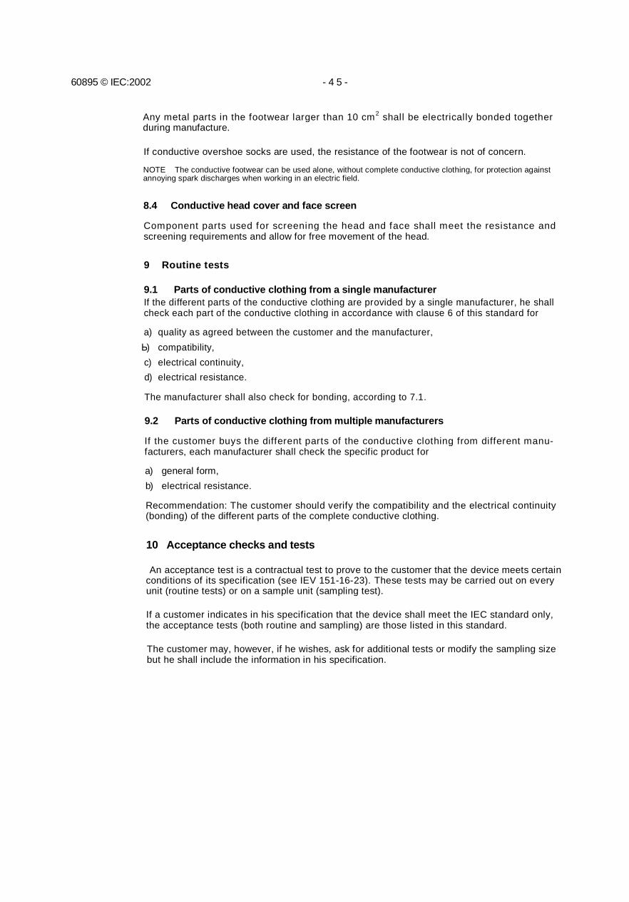
The test chamber (see figure 2) shall be made of steel plate not less than 1,5 mm thick.The interior walls of the chamber shall be painted matt black.
The chamber shall be composed of
a) a steel box 570 mm wide x 400 mm deep x 1 000 mm high, with one air vent each in thelower back and front. These air vents shall measure 116 mm in height and 440mm inlength;
b) a glass door above the front air vent;c) а 300 mm x 300 mm steel deflector plate above the top of the chamber, which is
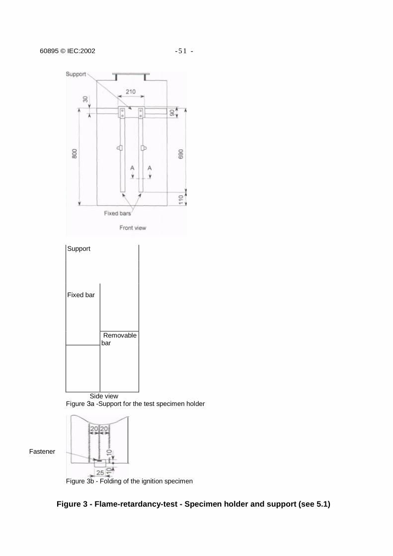
penetrated by a 200 mm diameter hole;d) a support for the test specimen holder (see figure За). The lower part of the test specimen
holder shall be placed 110 mm above the base of the chamber.
5.1.2.2 Test specimen holder
The test specimen holder (see figures За and 3b) shall be composed of
a) a support on which two 5 mm thick bars, spaced 150 mm apart, are fixed;b) two 5 mm thick holding (removable) bars held on the two fixed bars with clips.
The support and all the bars shall be made of metal.
The size of all bars shall be such that the test specimen is well supported.
5.1.2.3 Accessories
Accessories include
a) a standard ignition linen specimen: whitened, not dressed, composed of 67 % polyester,33% cotton- 110g/m2;
b) a clamp;c) clips;d) a weighing scale (0,001 g precision);e) a pattern for test specimen cutting;f) tracing paper;g) a mirror of approximately 250 mm x 300 mm, placed in a corner of the chamber, used to
observe the burning on the rear of the test specimen.
5.1.3 Test specimens
5.1.3.1 Shape and dimensions
Rectangular test specimens shall have dimensions of 150 mm x 300 mm after being attachedto the specimen holder.
For knitted material (for example, socks and gloves) the manufacturer shall provide flat testspecimens with the above dimensions.
60895 © IEC:2002 - 2 7 -
5.1.3.2 Quantity
The numbers of test specimens required according to the material shall be as follows.
a) Woven materialTests shall be performed on three test specimens which are cut so that their length is parallel withthe warp direction and three test specimens having their length parallel to the weft direction.
b) Knitted materialThree test specimens shall be provided for knitted material unless it is not directionally uniform. Inthis case, six test specimens shall be provided (three for each direction).
c) Layered materialThree test specimens shall be provided for layered material unless it is not directionally uniform. Inthis case, six test specimens shall be provided (three for each direction).
5.1.3.3 Preparation of samples
The outlines of the test specimens shall be marked on the material using the pattern set out in 5.1.3.1.The length of each specimen shall be appropriate to the direction specified in the test.
The test specimens shall be cut in such a way that
- the middle point is on a 45° oblique line vis-a-vis the edges of a roll of fabric,- the sides are parallel with the exterior edges of a roll of material.
The required number of test specimens shall be cut from the material in an area with no visibledefects. No specimens shall be taken within 50 mm from the selvage or edge of the material.
5.1.4 Test procedure
For each test specimen, the test procedure shall be as follows.
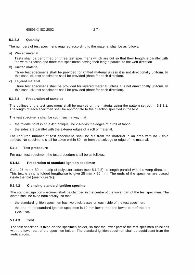
5.1.4.1 Preparation of standard ignition specimen
Cut a 25 mm x 80 mm strip of polyester cotton (see 5.1.2.3) its length parallel with the warp direction.This textile strip is folded lengthwise to give 25 mm x 20 mm. The ends of the specimen are placedinside the fold (see figure 3c).
5.1.4.2 Clamping standard ignition specimen
The standard ignition specimen shall be clamped in the centre of the lower part of the test specimen. Theclamp shall be fixed horizontally, so that
- the standard ignition specimen has two thicknesses on each side of the test specimen,- the end of the standard ignition specimen is 10 mm lower than the lower part of the test
specimen.
5.1.4.3 Test
The test specimen is fixed on the specimen holder, so that the lower part of the test specimen coincideswith the lower part of the specimen holder. The standard ignition specimen shall be equidistant from thevertical rods.
60895 © IEC:2002 - 2 9 -
The specimen holder is hung vertically in the test chamber.
Apply a flame to the lower part of the standard ignition specimen until it is ignited (about 2 s)and immediately close the door of the test chamber.
The standard ignition specimen shall burn normally for about 25 s to 30 s.
Observe the burning test specimen during the test and note the following:
- points of residual after-glow;- melting;- distortion of test specimen;- smoke.
5.1.4.4 Measurement of burned area
At the end of the test, and after 15 min in atmospheric conditions conforming to code 18 °C to28 "C/45 % to 75 % of IEC 60212,
- using scissors, remove the completely burned or melted areas,- lay the damaged test specimen flat on the pattern so that remaining contours coincide with
the pattern ones,- measure the burned area of the test specimen by cutting up and scaling the tracing paper,
by planimetry, or by measurement of a geometric area.
5.1.5 ResultsThe test is considered to be successful if the following conditions are met by each of the speciments
- the burned area of the test specimen is less than, or equal to, 100 cm2;- the burned area does not extend to the vertical parts of the specimen holder, nor to
theupper edge of the test specimen.
5.2 Electrical resistance test
Standard procedures to determine electrical resistance of material in connection with itsantistatic properties are unreliable when the electrical resistance of highly conductive materialhas to be determined. Indeed, these standard procedures do not take into account theinterference of the transition resistance from electrode to test specimen, which is of primaryimportance when low-resistance test specimens have to be measured.
5.2.1 Test equipment
The following apparatus is needed for the test:
- one alternating current source of power frequency (50 Hz or 60 Hz), or one direct currentsource, allowing an adjustable and regulated load current of up to 2 A at 30 V;
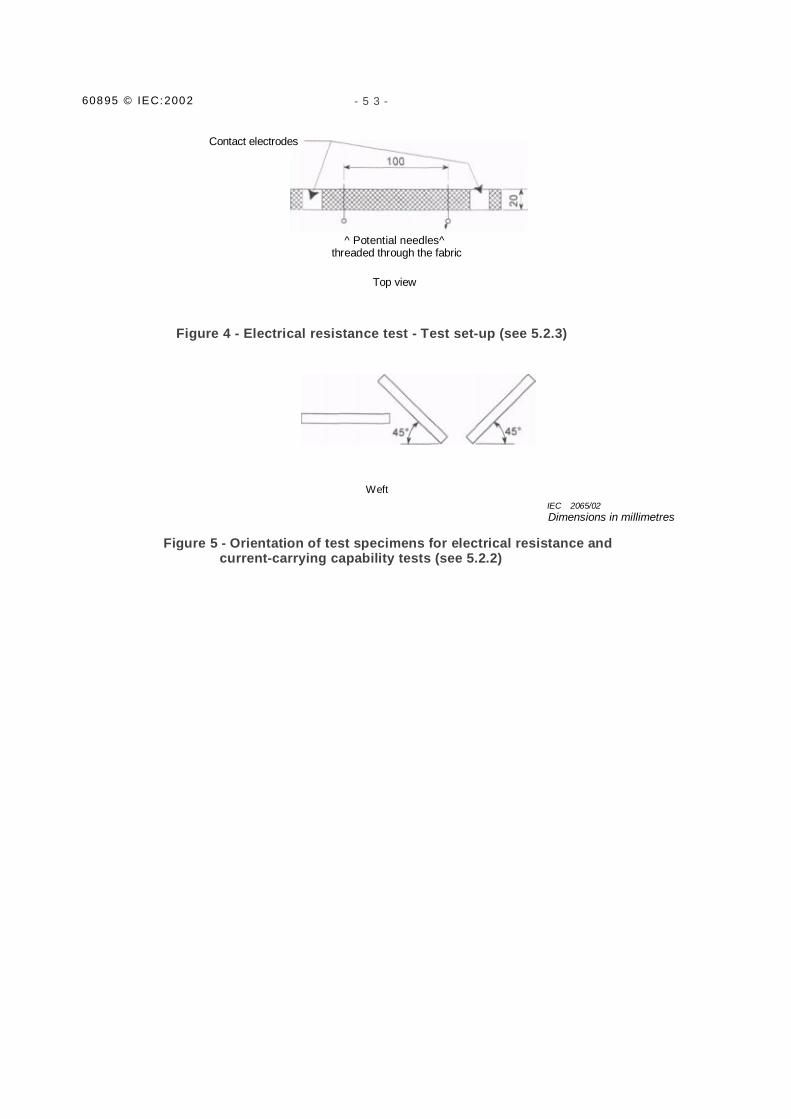
- one ammeter;- two contact electrodes, providing a contact surface of 20 mm x 20 mm on both faces of
the test specimen. Contact pressure shall be more than 100 kPa (see figure 4);- two voltage measuring electrodes, such as sewing pins or needles;- one voltmeter.
60895 © IEC:2002 - 3 1 -
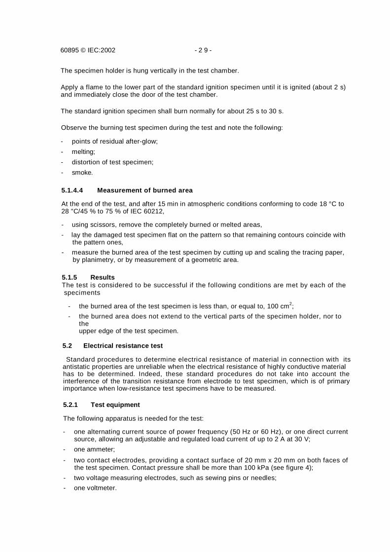
5.2.2 Preparation of test specimens
Four material test specimens measuring approximately 200 mm x 20 mm are respectively cutin warp, weft and two perpendicular directions making a 45° angle with warp and weft (seefigure 5). No specimens shall be taken within 50 mm from the selvage, or edge of thematerial.
These test specimens shall be tested successively after a 24 h conditioning using the code24h/23 °C/50 % of IEC 60212.
5.2.3 Procedure
The test specimen is placed unstretched between the contact electrodes (see figure 4).
The voltage measuring electrodes are threaded through the test specimen at a distance of100 mm apart (see figure 4).
The electrical circuit is completed (see figure 6). A 0,2 A current is established through theunstretched test specimen.
After 1 min the voltage is measured.
5.2.4 Test results
The voltage measured is proportional to the electrical resistance of the test specimen.
The electrical resistance of a unit square is given by the formula:
whereU is the measured voltage, in V;/ is the width of the test specimen, in mm;/ is the test current, in A;L is the length of the test specimen, in mm.
Numerical application (Rs in Ω and U in V):
RS = U/0,2Х20/100
NOTE The specimen resistance should be utilized by the manufacturer to establish the garment resistance limitrequired in 6.2 for the garment.
The arithmetic mean value of the four electrical values shall be lower than 7 Ω per square. Noindividual value shall be higher than 10 Q per square.
RS = Rmeasured X width/length = Uxl / IXL
60895 © IEC:2002 - 3 3 -
5.3 Current-carrying capability
This is the test to establish the capacity of the material to carry current without excessivedegradation to the material. The test is not to establish a heat comfort level.
5.3.1 Test equipment
The test-set shall be the same as in 5.2.1.
5.3.2 Preparation of test specimens
The preparation shall be the same as in 5.2.2.
5.3.3 Procedure
The procedure shall be as in 5.2.3 except that a 1 A current is established through the testspecimen for a duration of 15 min. This current and its time duration are well in excess ofanticipated working conditions.
5.3.4 Test results
During the test, there shall be no flame, incandescent point, smoke or carbonization betweenthe contact electrodes.
5.4 Shielding efficiency
Tests carried out in the actual conditions of this standard have shown that shielding efficiencydoes not depend on test frequency between 50 Hz and 5 kHz. To facilitate testing, 5 kHz ischosen. At this frequency, the test is at least as severe as at 50 Hz or 60 Hz.
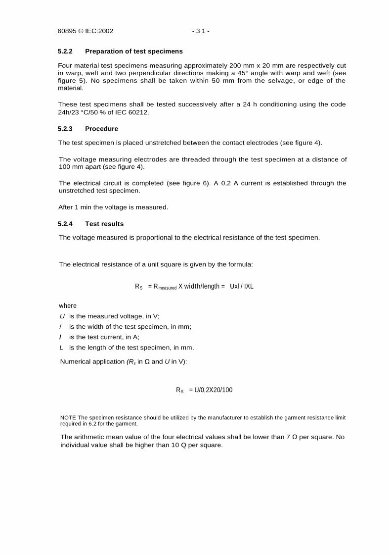
5.4.1 Test equipment
The test equipment is composed of the following:
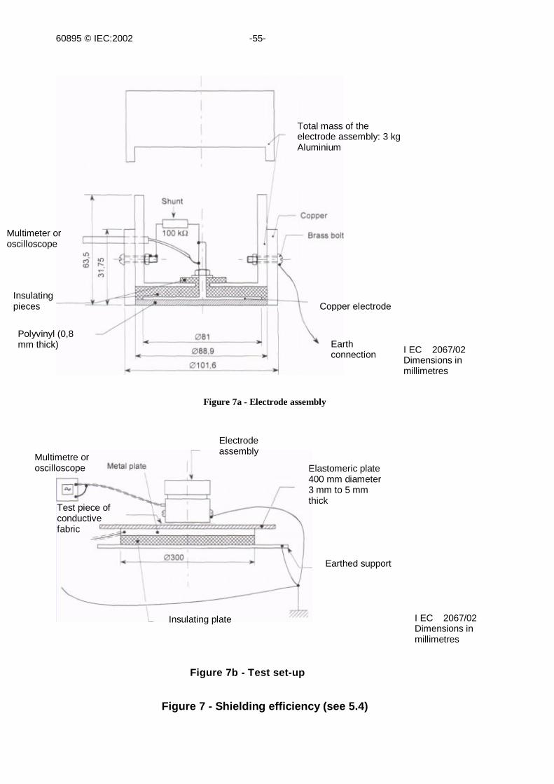
a) one 400 V r.m.s. sine wave voltage generator at 5 kHz;b) one insulating circular plate 300 mm in diameter;с) one metallic circular plate 300 mm in diameter with connection clip;d) one insulating circular plate 400 mm in diameter made from an elastomeric (3,5 ± 0,5) mmthick sheet having a surface hardness between 60° and 65° on the Shore scale;e) one electrode assembly weighing 3 kg built according to the scheme given in figure 7a
and fitted with a 100 kΩ shunt;f) one measuring device (multimeter or oscilloscope) with constant input impedance greater
than, or equal to, 1 MQ, in parallel with a capacitance of 47 pFthan, or equal to, 1 MQ, in parallel with a capacitance of 47 pF maximum;
g) one voltmeter allowing measurement of 400 V r.m.s. at 5 kHz.
The following parts are assembled in the specified order upon a grounded horizontal support(figure 7b):
- circular insulating plate 300 mm in diameter (item b of 5.4.1); - circular metalplate 300 mm in diameter and 3 mm to 5 mm thick (item с of 5.4.1);
5.4.2 Test mounting
60895 © IEC:2002 - 3 5 -
- circular elastomeric plate 400 mm in diameter and 3 mm to 5 mm thick (item d of 5.4.1);- test specimen, minimal dimensions 120 mm x 120 mm;- electrode assembly (not allowed to pass beyond the edge of test specimen). The
thickness of the polyvinyl insulating plate between the electrode and the test specimenshall be 0,8 mm (figure la).
5.4.3 Earth connection
The following parts are connected together and earthed:
- frame connection of voltage generator;- earth connection of electrode assembly;- frame connection of voltmeter.
5.4.4 Line connection
The following parts are connected together and insulated from earth:
- line connection of voltage generator;- connection clip of metallic plate 300 mm in diameter;- line connection of voltmeter.
5.4.5 Test procedure
5.4.5.1 Determination of reference voltage
Without the material specimen, a voltage of 400 V r.m.s. at 5 kHz is applied between the lineand earth connections. The voltage is read on the measuring device and noted as £/ref.
5.4.5.2 Measuring with test specimen
The test specimen is installed (5.4.2) and the test procedure is carried out in the same way asdescribed in 5.4.5.1. The measured voltage U is recorded.
5.4.5.3 Acceptance criteria
Shielding efficiency is given by the formula
S£dB = 20 Iog10[Uref /U]
The shielding efficiency shall be greater than 40 dB.
5.5 Resistance to cleaning
To ensure that the efficiency and flame-retardant properties of the clothing do not deteriorateexcessively after repeated cleaning, both of the following procedures (laundering and dry-cleaning) shall be carried out. If the garment can be cleaned by one of the two methods, butnot by the other, the manufacturer shall mark the garment accordingly, and only theappropriate method need be used.
5.5.1 Laundering
Material sufficient to conduct flame-resistance testing and shielding efficiency, plus ballastrequired to make a full load shall be washed in accordance with ISO 6330.
60895 © IEC:2002 - 3 7 -
5.5.1.1 Test apparatus
The apparatus and reagents shall have the following specifications.
a) Automatic washing machine capable of being operated under the following conditions:
- either a top-loading, agitator type with a "normal" agitator speed of (70 ± 5) r/min, or afront-loading machine with a speed of 52 r/min, revolving alternatively in each directionfor 12s, with 3 s rest in between,
- washing time adjustment controllable between 0 min and 15 min, with a toleranceof ±1 min,
- spin speed: normal (515 ± 5) r/min.
b) Drier of the rotary tumble type having a cylindrical basket approximately 750 mm in diameterand not less than 400 mm in depth, rotating at approximately (50 ± 5) r/min, equipped withmeans for maintaining a drying temperature of 50 °C to 70 °C measured in the exhaustvent as close as possible to the drying cylinder, and providing a cooling period of 5 minwhen tumbling at the end of the drying cycle.
c) Commercial detergent not containing bleach. The standard detergent specified intable E.1 of IEC 60456 for a detergent without perborate (type II), can be used in cases ofdispute.
d) Dummy load: pieces of undyed spun polypropylene fabric, having a mass of approximately0,16kg/m2.
5.5.1.2 Test procedure
Place the test specimens in the washing machine and add sufficient dummy load to make atotal dry load of 2 kg. Fill the machine to operate with (40 ± 4) I of water and set the machineto operate at the normal setting (50 °C to 70 °C). If the mass of the test specimen(s) exceeds2 kg, the amount of water shall be increased proportionately.
Add sufficient household use detergent to provide good running suds and set the machine towash for 10 min. (If necessary, advance the operation of the machine manually to begin therinse cycle after 10 min of washing.) Continue until the end of the final spin cycle.
On completion of the final spin cycle, remove the specimens from the machine and placethem and the dummy load (if any) in the tumble drier with the temperature of the exhaust fromthe drum set at 65 °C to 70 °C (for normal material). Operate the drier until the load is dry andcontinue tumbling, with the heat turned off, for 5 min. Remove the test specimensimmediately. One wash-dry cycle will then have been completed.
5.5.2 Dry-cleaning
Material sufficient to conduct flame-resistance testing and shielding efficiency, plus ballastrequired to make a full load shall be dry-cleaned in accordance with ISO 3175.
5.5.2.1 Test apparatus
The apparatus and reagents shall have the following specifications.
The apparatus shall consist of a cylinder, preferably of metal approximately 330 mm high and220 mm in diameter (capacity approximately 11 I). The cylinder shall be mounted on an axisinclined at an angle of 50° to the axis of the cylinder when the latter is in a vertical position.100 % perchlorethylene, dry and free from acid, is used.
60895 © IEC:2002 - 3 9 -
5.5.2.2 Test procedure
The material to be tested plus the ballast required, if any, are placed in the cylinder.
The cylinder is filled approximately one-third full with 100 % perchlorethylene, dry and freefrom acid, and rotated about its axis at a speed of 45 r/min to 50 r/min.
The test specimens are then taken from the cylinder and excess solvent removed from themby convenient means, such as centrifuging or squeezing between layers of white cotton clothor white blotting paper. They are then laid on a muslin-covered frame or a non-rusting, metalscreen. Heavy wrinkles are smoothed out with the hand and the test specimens are allowed todry at room temperature.
One dry-cleaning cycle will then have been completed.
5.5.3 Acceptability of material
When 10 wash-dry cycles, and/or 10 dry-cleaning cycles, have been completed, the testspecimens shall be placed on a flat surface and conditioned to the atmosphere for at least4 h, and the shielding efficiency (see 5.4.5) and flame-retardancy tests (see 5.1.4) repeated.If the values measured in these tests no longer meet the specified requirements, the materialshall be rejected.
6 Type tests of garment
6.1 General
Care shall be taken, if the garment is made up of more than one piece (for example, separatejacket or trousers), to ensure that the method of attachment (bonding) of the individual piecesis electrically continuous. The overlap of the individual component parts shall be such as toensure that the body of the worker is totally covered.
6.2 Electrical resistance
The electrical resistance shall be measured between the points indicated in 6.2.2. Electrodesshall be at least 50 mm from the edge of the garment or joint location.
Measurements shall be made with the garment mounted on (supported by) a mannequin ofnon-conductive material (dummy) supporting the garment, to conform to the shape it willassume when worn by the worker, or they may be made with the garment flat on a non-conductive table.
6.2.1 Test procedure
The test shall be made using an adequate a.c. or d.c. source to supply 200 mA for 1 min.
Weights of 2,27 kg shall be applied to each wrist and ankle cuff to maintain "standard"conductive fibre contacts during the test. If weights are not available, sufficient pressure maybe achieved by applying pressure with the hand to obtain lowest reading. A working belt shallbe secured around the waist to obtain a good contact between the upper and lower portions ofa two-piece garment. When a two-piece garment is tested flat on a non-conductive table, theworking belt is replaced by a sufficient weight applied over the connection between trousersand jacket, to keep both parts together and to give good electrical contact.
60895 © IEC:2002 - 4 1 -
Readings shall be made using electrodes with 25 mm2 contact area and with adequatepressure. Readings shall include the electrode contact resistance.
Measurements shall be carried out after 1 min of current circulation.
6.2.2 Measurement locations
For all garments, measu6.2.2 Measurement locationsa) For all garments, measu rements shall be made between electrodes located approximately
50 mm from the fabric edge.b) Points to be measured, as appropriate, are as follows:
- right wrist cuff to left wrist cuff;- right ankle cuff to left ankle cuff;- each wrist cuff to opposite ankle cuff.
6.2.3 Acceptable values
The garment shall be considered acceptable if the average resistance value measuredbetween these points does not exceed 50 Ω.
When separate items of the garment are purchased, the manufacturer and the customer mayagree to measurement points.
7 Type tests of the complete clothing
7.1 Bonding test
All component parts of the conductive clothing intended for use together shall be assembledaccording to the manufacturer's instructions. The bonding resistance between the garmentand any component parts shall not exceed 100 Q.
The measurements required shall be made as specified using the procedure described in6.2.1. The measurement locations are the following:
- from the wrist of the glove to each jacket wrist cuff;- each bonding lead to its attachment point on the garment;- hood, head cover, or face screen, to the neck of the garment or jacket.
Readings may be made using electrodes as described in annex D. However, the readingsobtained shall be equal to, or less than, those required. The contact resistance of theelectrodes should be included in the above readings.
7.2 Efficiency of conductive clothing
This test shall be carried out at 462 kV r.m.s., which is the maximum phase/earth powerfrequency voltage for which the clothing is used. The ground shall, as a minimum, be at adistance D given by the formula
D = Utest / 100 + 0,5 (with D in metres and L in kilovoltsj
The mannequin shall be conductive to simulate a human body. It shall be equipped with (seealso figure 8)
- a conductive belt placed against the mannequin;

60895 © IEC:2002 - 4 3 -
- an insulating suit;
- the complete conductive clothing under test (which includes the face screenor other means to protect the face).
Good insulation between the conductive clothing and the conductive beltworn by the mannequin shall be checked before and after the test.
Direct reading is made on the shielded ammeter of
- the total current /1, f lowing between the live electrode and theconductive clothingconnected to its conductive belt,
- the current /2 flowing between the live electrode and the conductive belt.
The ratio /1 / /2 shall be such that the efficiency coefficient /1 / (I1+ I2) x 100shall be not less than 99 %.
8 Type test of the component parts
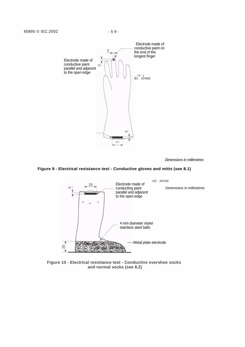
8.1 Conductive gloves and mitts
Two electrodes shall be painted on the glove or mitt using conductive painthaving the characteristics described in annex D, or other acceptableelectrodes (see annex D and figure 9). The reading shall be recorded.
To provide protection from spark discharges directly to the hand through thematerial, the spacing between individual adjacent conductive components inthe material shall not exceed 5 mm even when the material is stretched with aforce of up to 50 N in any direction. No holes are permitted. Spacing can beverified by a visual inspection.
8.2 Conductive overshoe socks and normal socks
An electrode 25 mm long and parallel to the open edge of the overshoe sock orthe normal sock and about 5 mm wide shall be painted on the specimen usingconductive paint having the characteristics described in annex D, or otheragreed-upon electrodes may be used. The sole of the overshoe sock or of thesock shall then be placed on a metal plate and 4 mm diameter nickel stainlesssteel balls, conforming to ISO 3290, poured into the overshoe sock or into thesock to a depth of 20 mm (see figure 10). The resistance shall then be measuredbetween the electrode and the metal plate. The readings shall be recorded.
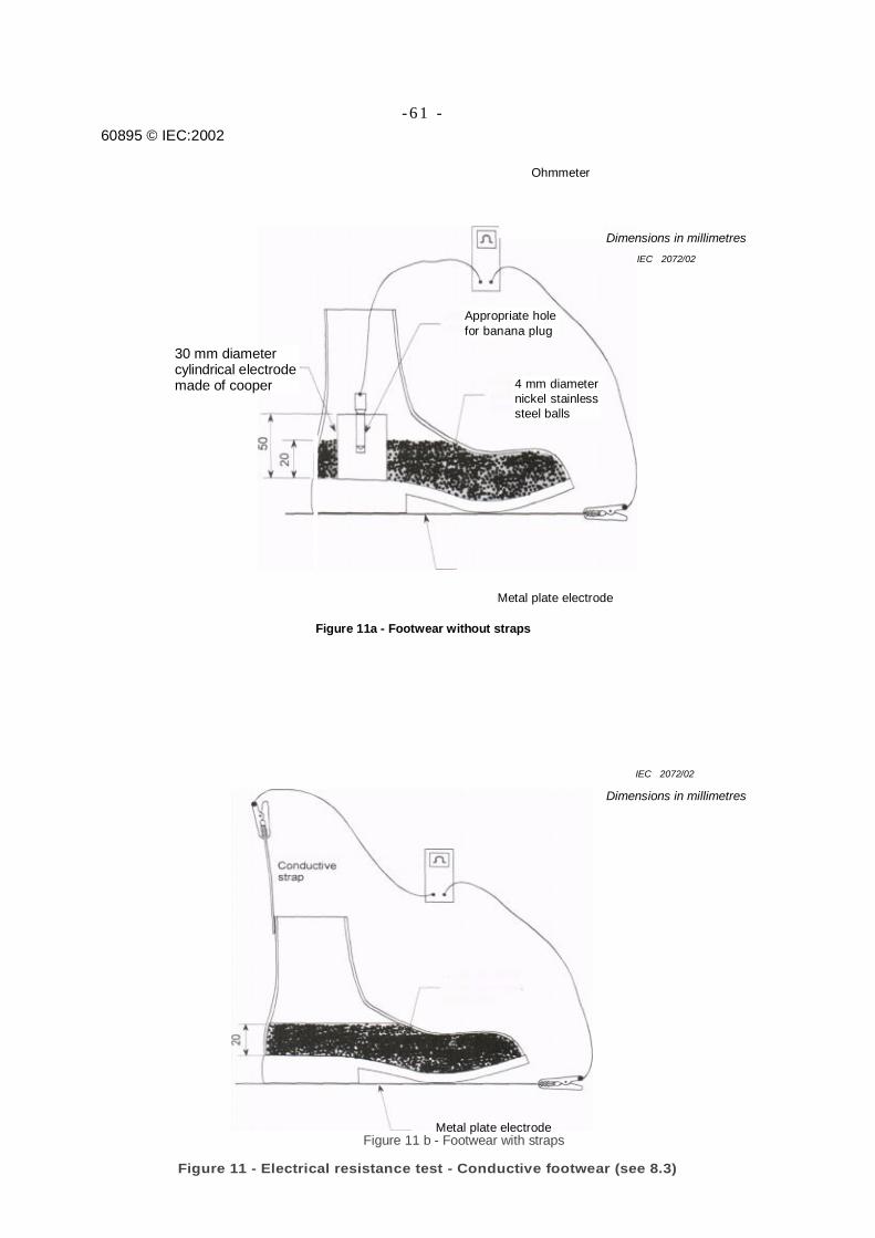
8.3 Conductive footwear
The footwear shall be placed on a metal plate and one electrode placed on theinside below the ankle opening. Nickel stainless steel balls 4 mm in diameter,conforming to ISO 3290, shall then be poured in and around the electrode tocover the complete sole to a depth of 20 mm at the heel (see figure 11 a).
The resistance shall then be measured between the metal plate and theelectrode according to the procedure and shall be between the range 0 kQ to 10kΩ.
If straps are used to connect the footwear electrically to the conductiveclothing, then the resistance shall be measured between the strap and the metalplate on which the footwear is resting, with the steel balls inside but notconnected in the circuit (see figure 11b).
60895 © IEC:2002 - 4 5 -
Any metal parts in the footwear larger than 10 cm2 shall be electrically bonded togetherduring manufacture.
If conductive overshoe socks are used, the resistance of the footwear is not of concern.
NOTE The conductive footwear can be used alone, without complete conductive clothing, for protection againstannoying spark discharges when working in an electric field.
8.4 Conductive head cover and face screen
Component parts used for screening the head and face shall meet the resistance andscreening requirements and allow for free movement of the head.
9 Routine tests
9.1 Parts of conductive clothing from a single manufacturerIf the different parts of the conductive clothing are provided by a single manufacturer, he shallcheck each part of the conductive clothing in accordance with clause 6 of this standard for
a) quality as agreed between the customer and the manufacturer, Ь) compatibility,
c) electrical continuity,d) electrical resistance.
The manufacturer shall also check for bonding, according to 7.1.
9.2 Parts of conductive clothing from multiple manufacturers
If the customer buys the different parts of the conductive clothing from different manu-facturers, each manufacturer shall check the specific product for
a) general form,b) electrical resistance.
Recommendation: The customer should verify the compatibility and the electrical continuity(bonding) of the different parts of the complete conductive clothing.
10 Acceptance checks and tests
An acceptance test is a contractual test to prove to the customer that the device meets certainconditions of its specification (see IEV 151-16-23). These tests may be carried out on everyunit (routine tests) or on a sample unit (sampling test).
If a customer indicates in his specification that the device shall meet the IEC standard only,the acceptance tests (both routine and sampling) are those listed in this standard.
The customer may, however, if he wishes, ask for additional tests or modify the sampling sizebut he shall include the information in his specification.
895 © IEC:2002 - 47 -
The customer may wish to witness the tests, have someone witness them or simply accept the results of thetests as carried out by the manufacturer. He may also specify that the tests be carried out in anindependent laboratory of his choosing or even in his own laboratory.Further, the customer may specify additional tests or larger sampling sampling sizes when he is purchasingfrom a new manufacturer.
11 Modification
Before carrying out any modification of any characteristic after the purchase agreement has been made,whether specified herein or not, the manufacturer shall obtain the agreement of the customer.
Any modif ication of the conductive clothing may require new type tests, in whole or in part (if the degree ofmodification so justifies), as well as a change in clothing reference literature.
Boot or shoe/EC 2059/02
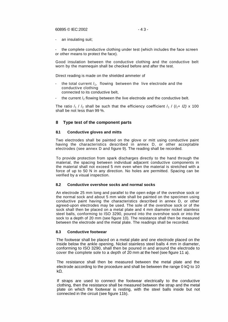
Figure 1 - Example of general arrangement of complete conductive clothing
(see clause 3)
Hat
Hoodand/or facescreen
Garment
GloveJacket or upperpart of the garment
Pants or lower partof the garment
Sock
Overshoesock
Bondinglead
60895 © IEC:2002
- 4 9 -
Figure 2 - Flame-retardancy test - Test chamber (see 5.1)
60895 © IEC:2002 - 5 1 -
Support
Fixed bar
Removablebar
Side viewFigure За -Support for the test specimen holder
Figure 3b - Folding of the ignition specimen
Figure 3 - Flame-retardancy-test - Specimen holder and support (see 5.1)
Fastener
60895 © IEC:2002 - 5 3 -
Contact electrodes
^ Potential needles^threaded through the fabric
Top view
Figure 4 - Electrical resistance test - Test set-up (see 5.2.3)
WeftIEC 2065/02Dimensions in millimetres
Figure 5 - Orientation of test specimens for electrical resistance andcurrent-carrying capability tests (see 5.2.2)
60895 © IEC:2002 -55-
Figure 7a - Electrode assembly
Figure 7b - Test set-up
Figure 7 - Shielding efficiency (see 5.4)
Polyvinyl (0,8mm thick)
Copper electrode
Multimeter oroscilloscope
Total mass of theelectrode assembly: 3 kgAluminium
Insulatingpieces
Earthconnection
Electrodeassembly
Elastomeric plate400 mm diameter3 mm to 5 mmthick
Earthed support
Insulating plate
Test piece ofconductivefabric
Multimetre oroscilloscope
I EC 2067/02Dimensions inmillimetres
I EC 2067/02Dimensions inmillimetres

60895 © IEC:2002 - 5 7 -
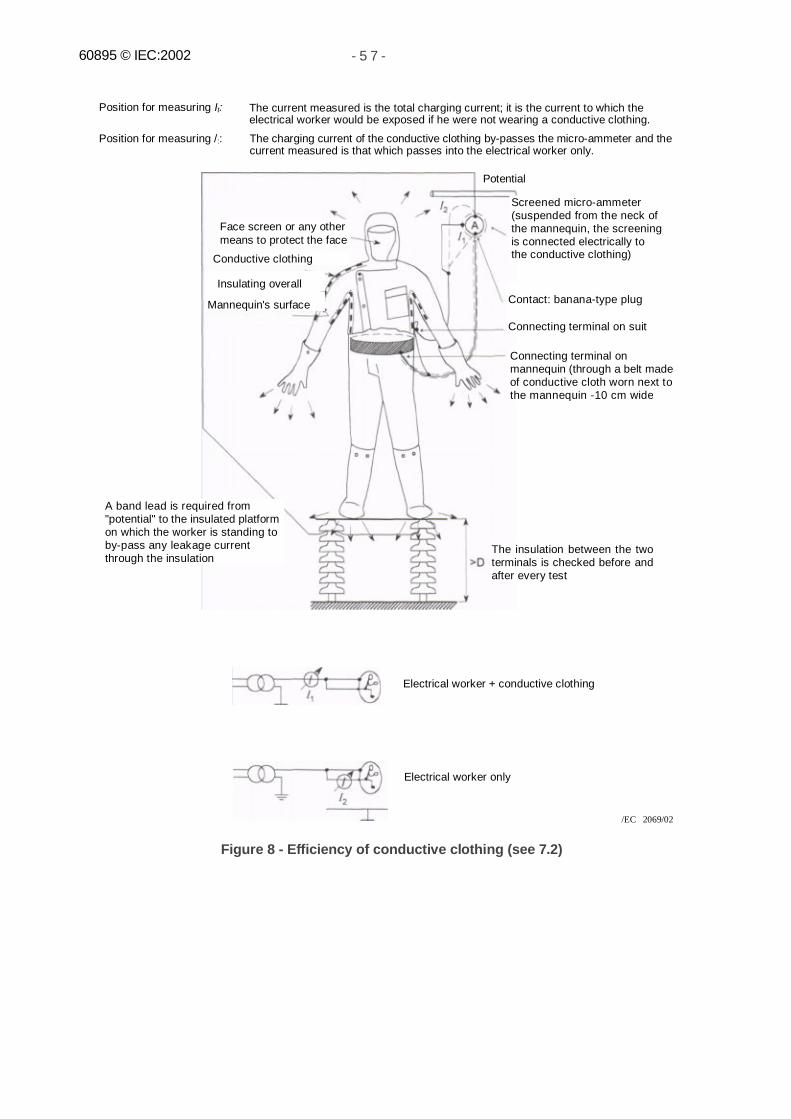
Position for measuring It:
Position for measuring /::
The current measured is the total charging current; it is the current to which theelectrical worker would be exposed if he were not wearing a conductive clothing.
The charging current of the conductive clothing by-passes the micro-ammeter and thecurrent measured is that which passes into the electrical worker only.
Electrical worker + conductive clothing
Electrical worker only
/EC 2069/02
Figure 8 - Efficiency of conductive clothing (see 7.2)
Potential
Screened micro-ammeter(suspended from the neck ofthe mannequin, the screeningis connected electrically tothe conductive clothing)
Face screen or any othermeans to protect the face
Conductive clothing
Insulating overall
Mannequin's surface Contact: banana-type plug
Connecting terminal on suit
Connecting terminal onmannequin (through a belt madeof conductive cloth worn next tothe mannequin -10 cm wide
A band lead is required from"potential" to the insulated platformon which the worker is standing toby-pass any leakage currentthrough the insulation
The insulation between the twoterminals is checked before andafter every test
60895 © IEC:2002 - 5 9 -
Electrode made ofconductive paint onthe end of thelongest finger
Electrode made ofconductive paintparallel and adjacentto the open edge
_ ^3 _|IEC 2070/02
Dimensions in millimetres
Figure 9 - Electrical resistance test - Conductive gloves and mitts (see 8.1)
I EC 2071/02
Dimensions in millimetres
Figure 10 - Electrical resistance test - Conductive overshoe socksand normal socks (see 8.2)
Electrode made ofconducting paintparallel and adjacentto the open edge
4 mm diameter nickelstainless steel balls
----Metal plate electrode
60895 © IEC:2002- 6 1 -
Dimensions in millimetresIEC 2072/02
Figure 11a - Footwear without straps
IEC 2072/02
Dimensions in millimetres
Figure 11 b - Footwear with straps
Figure 11 - Electrical resistance test - Conductive footwear (see 8.3)
Ohmmeter
Appropriate holefor banana plug
30 mm diametercylindrical electrodemade of cooper 4 mm diameter
nickel stainlesssteel balls
Ohmmeter
4 mm diameternickel stainlesssteel balls
Metal plate electrode
Metal plate electrode

60895 © IEC:2002 - 6 3 -
Annex A(normative)
Suitable for live working(double triangle) (IEC-60417-5216)
/EC 2074/02
60895 © IEC:2002 - 6 5 -
Annex В(normative)
Classification of tests
B.1 Tests on conductive material
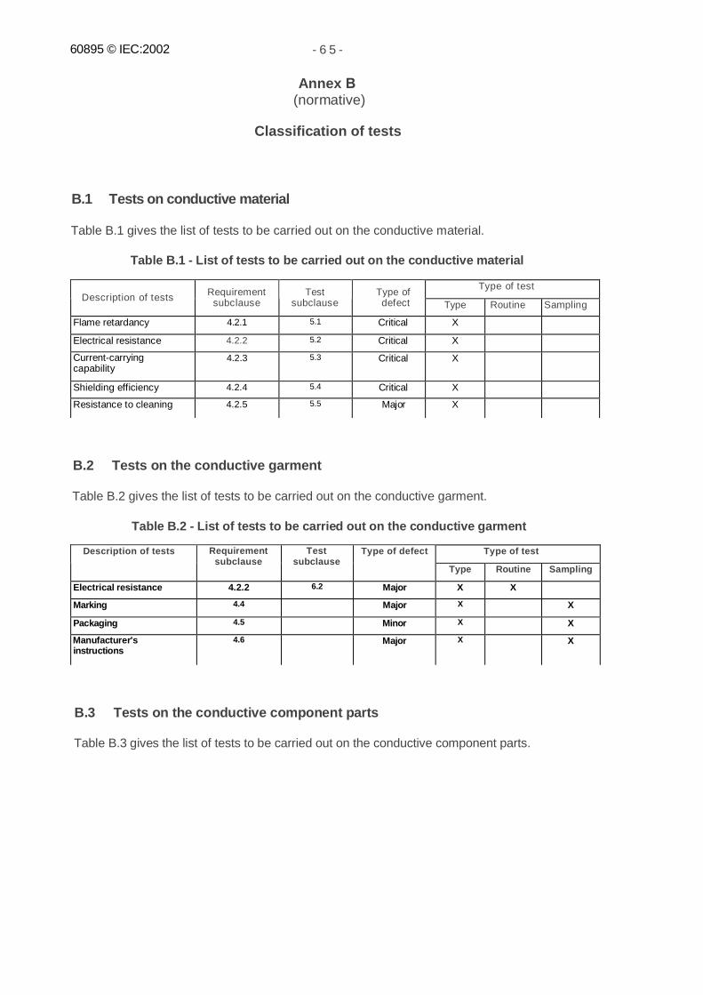
Table B.1 gives the list of tests to be carried out on the conductive material.
Table B.1 - List of tests to be carried out on the conductive material
Type of testDescription of tests Requirement
subclauseTest
subclauseType ofdefect Type Routine Sampling
Flame retardancy 4.2.1 5.1 Critical X
Electrical resistance 4.2.2 5.2 Critical X
Current-carryingcapability
4.2.3 5.3 Critical X
Shielding efficiency 4.2.4 5.4 Critical X
Resistance to cleaning 4.2.5 5.5 Major X
B.2 Tests on the conductive garment
Table B.2 gives the list of tests to be carried out on the conductive garment.
Table B.2 - List of tests to be carried out on the conductive garment
Type of testDescription of tests Requirementsubclause
Testsubclause
Type of defect
Type Routine Sampling
Electrical resistance 4.2.2 6.2 Major X X
Marking 4.4 Major X X
Packaging 4.5 Minor X X
Manufacturer'sinstructions
4.6 Major X X
B.3 Tests on the conductive component parts
Table B.3 gives the list of tests to be carried out on the conductive component parts.
60895 © IEC:2002 - 67 -
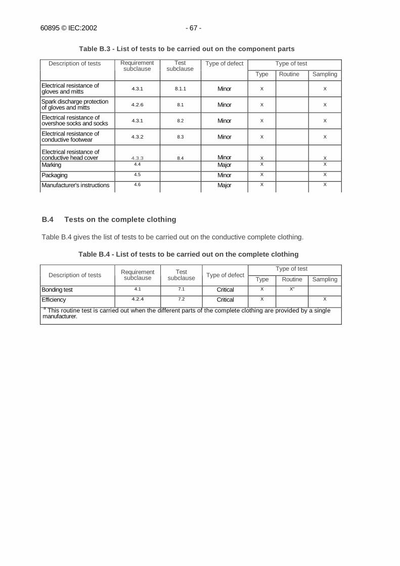
Table B.3 - List of tests to be carried out on the component parts
Type of testDescription of tests Requirementsubclause
Testsubclause
Type of defect
Type Routine Sampling
Electrical resistance ofgloves and mitts 4.3.1 8.1.1 Minor X X
Spark discharge protectionof gloves and mitts 4.2.6 8.1 Minor X X
Electrical resistance ofovershoe socks and socks 4.3.1 8.2 Minor X X
Electrical resistance ofconductive footwear 4.3.2 8.3 Minor X X
Electrical resistance ofconductive head cover 4.3.3 8.4 Minor X XMarking 4.4 Major X X
Packaging 4.5 Minor X X
Manufacturer's instructions 4.6 Major X X
B.4 Tests on the complete clothing
Table B.4 gives the list of tests to be carried out on the conductive complete clothing.
Table B.4 - List of tests to be carried out on the complete clothing
Type of testDescription of tests Requirement
subclauseTest
subclause Type of defectType Routine Sampling
Bonding test 4.1 7.1 Critical X X"
Efficiency 4.2.4 7.2 Critical X X
a This routine test is carried out when the different parts of the complete clothing are provided by a singlemanufacturer.
60895 © IEC:2002 - 6 9 -
Annex С(normative)
Sampling procedure
C.1 General
The sampling procedure for this product does not follow in its entirety the sampling proceduredeveloped in ISO 2859-1. The product covered by this standard does not lend itself to theapplication of the above-mentioned standard due to its nature.
The sampling procedure used in conjunction with this standard has been specially developedon the basis of the quality assurance practice of the ISO 9000 series. When thoserequirements (ISO 9000) are not followed, the procedure of this annex is applicable.
C.2 Classification of defects
Defects are classified as critical, major or minor (see clause 2 of IEC 61318). Annex В givesthe defect classification for the tests retained for the sampling procedure.
C.3 General sampling plan
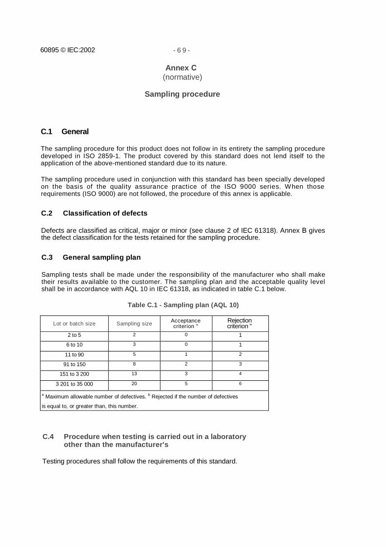
Sampling tests shall be made under the responsibility of the manufacturer who shall maketheir results available to the customer. The sampling plan and the acceptable quality levelshall be in accordance with AQL 10 in IEC 61318, as indicated in table C.1 below.
Table C.1 - Sampling plan (AQL 10)
Lot or batch size Sampling size Acceptancecriterion "
Rejectioncriterion "
2 to 5 2 0 1
6 to 10 3 0 1
11 to 90 5 1 2
91 to 150 8 2 3
151 to 3 200 13 3 4
3 201 to 35 000 20 5 6
a Maximum allowable number of defectives. b Rejected if the number of defectives
is equal to, or greater than, this number.
C.4 Procedure when testing is carried out in a laboratoryother than the manufacturer's
Testing procedures shall follow the requirements of this standard.
60895 © IEC:2002 - 71 -
Annex D(informative)
Electrodes for determining electrical resistance properties ofmaterial specimen and garments
D.1 General
The type of electrode used to determine the electrical resistance of the material specimen isthat specified and described in figure 4. The potential electrodes are to be threaded throughthe specimen as indicated in figure 4.
For conductive clothing the electrodes may be of different design but must have a contactarea of at least 25 mm2 and have a contact pressure of 100 kPa. The voltage drop due to theelectrode contact shall be included in the measurement.
The type of electrodes does not significantly influence the overall reading. Crabclaws, clips orpads affixed to the material may be used. The contact surface shall be at least 25 mm2 andthe contact pressure shall be 100 kPa, required to reduce the contact resistance and obtainthe lowest reading.
D.2 Conductive paint
Conductive paint may provide the lowest contact resistance as it soaks into the fabric. If paintis used, it should meet the following criteria:
- colloidal silver paint is recommended;- before a conductive paint is used as an electrode material, it should be established that
the solvent in the paint does not attack the material so as to change its electricalproperties.
06895 © IEC:2002 - 7 3 -
Annex E(informative)
Recommendations for the in-service care, maintenance andperiodic testing of conductive clothing and componentparts
E.1 Care, storage and repair
E.1.1 Care
The integrity of the conductive clothing is essential. It is the responsibility of theworker to exercise extreme care while wearing and handling the conductive clothing.Tears, holes and other deformities should be repaired according to accepted practiceas described in E.1.4.
E.1.2 Storage
Conductive clothing, and component parts should be stored in a dustproofbreathable container, such as a canvas or vinyl bag or briefcase. The containershould be breathable in order to allow any moisture in the conductive clothing to dry,rather than turn mouldy. The storage container should be easily identified and storedin a location safe from heat, moisture and damage from other stored items. Careshould be taken in transport. Conductive clothing should not be stored when madedamp by perspiration or other moisture.
E.1.3 Cleaning
The manufacturer's cleaning instructions should be followed. In general, theconductive clothing may be washed by hand or in an automatic washer with adetergent and no other additives (bleach, etc.) and may be dried in an automaticdryer on low heat or air-dried.
The life of the conductive clothing may be prolonged by hand washing with milddetergent and air-dried. Conductive clothing that is heavily soiled with grease,oil or other heavy contaminants should be dry cleaned.
E.1.4 Patching and repair
Snags and rips can be sewn with flame-retardant thread. Holes can be repaired byusing a patch of the conductive clothing material and by stitching a 2,54 cmoverlap with flame-retardant thread.
NOTE When conductive clothing is damaged beyond repair and needs to be retired fromservice, it is recommended that it be returned to the manufacturer along with a complete history of itsuse and care, in order to provide a database for future review.
Socks and gloves are not repairable.
60895 © IEC:2002 - 7 5 -
Е.2 Inspection before use
E.2.1 General
Before each day's use, a visual inspection should be made of the complete conductiveclothing to ensure that all component parts fit together.
Zip fasteners, metal press-studs, metal hooks and eyes (gallow straps or suspenders) shouldbe checked to ensure that they are correctly inserted and making a good contact. Thestitching should be examined to ensure that it is continuous and that two or more pieces,when joined, stay in good contact.
Adjustable self-gripping devices may be used to eliminate the need for metal fasteners.
E.2.2 Conductive clothing
Conductive clothing should be carefully examined by the wearer to be sure it is not damagedand that the bonding leads are secure.
E.2.3 Conductive boots and leg straps
The straps between the conductive boots and the calf should be inspected for breaks thatwould disrupt electrical continuity. They should be replaced if they are judged inadequate.
The soles of the boots should be kept clean and free from dirt and contaminants.
E.2.4 Conductive socks and gloves
Conductive socks and gloves should be inspected for damage.
E.3 Non-destructive periodic testing
E.3.1 General
Conductive clothing should be tested for resistance, either on a mannequin or flat, on a non-conductive table. A weight of 2,27 kg should be used at each wrist and ankle cuff to providefor proper and repeatable contact between fibres within the material. The resistance may bemeasured using either an a.c. source with current and voltage meters, or with d.c. source anddigital multimeter to read the resistance directly. Digital multimeters provide adequatesensitivity and accuracy for these measurements.
E.3.2 Test frequency
Testing is recommended at least every five years, or after five washings, whichever comesfirst.
60895 © IEC:2002 - 7 7 -
Е.3.3 Resistance test
When worn, conductive clothing should register continuity between any two extremities of thematerial. The required actual ohmic value will depend upon the electric field in which theworker will be exposed. New material will meet the limits set in the text: 50 Q for theconductive clothing and a maximum of 100 Q for the component bonding when testedaccording to this standard.
If the in-service test exceeds three times the original manufacturer's test values, the use ofthe conductive clothing should be investigated.
The garment test should be performed as given in clause 6 and bonding test as given in 7.1.
E.3.4 Record keeping
A complete chronological record of the conductive clothing used, its condition and test resultsshould be retained so that the user can establish his own replacement parameters based onthe specific tasks, use of the conductive clothing and care given the garment and componentparts.


![EN 300 253 - V2.1.1 - Environmental Engineering (EE ... · 7 etsi en 300 253 v2.1.1 (2002-04) [7] IEC 60050-826: "International Electrotechnical Vocabulary. Electrical installations](https://img.pdfslide.net/doc/110x75/5b4100ce7f8b9a860d8b4c8d/en-300-253-v211-environmental-engineering-ee-7-etsi-en-300-253-v211.jpg)