Embed Size (px)
Citation preview

Normstahl OSF42FG
Product datasheet
Q3.1 - 2019

Product datasheetNormstahl OSF42FG
Copyright and Disclaimer NoticeAlthough the contents of this publication have been compiled with the greatest possible care, Entrematic cannotaccept liability for any damage that might arise from errors or omissions in this publication. We also reserve the rightto make appropriate technical modifications/replacements without prior notice.
No rights can be derived from the contents of this document.
Color guides: Color differences may occur due to different printing and publication methods.
Entrematic® and Normstahl® as words and logos are registered or unregistered trademarks belonging toEntrematic Group AB.
Copyright © Entrematic Group AB 2006-2019.
No part of this publication may be copied or published by means of scanning, printing, photocopying, microfilm or anyother process whatsoever without prior permission in writing by Entrematic Group AB.
All rights reserved.
2

Product datasheetNormstahl OSF42FG
Technical factsFeatures
Performance
* Higher wind load classification on request
Max size: (W x H)* 5500 mm x 4250 mm
Frame thickness: 44 mm
Frame material: Aluminium tubular frames
Filling: Windows
≤DLW 3300mm, 1 pane
>DLW 3300mm, 2 panes
Color outside: Natural aluminium
Color inside: Natural aluminium
Track types: Standard: SL
Optional: HL, LL, VL, HHL
Windows: SH6: 6 mm HG
Electrical operation: Optional: Automated operation, Access control, Safety functions
Opening/closing speed: IDO7: 0,25 m/sIDO7 HD: 0,18 m/sIDO7 2H: opening 0,5 m/s, closing 0,25 m/s
Life time expectations: Door: 100.000 door cycles or 10 years (in a normal industrial environment)
Springs: 20.000 door cycles
Wind load, EN12424* Class 3 (≤ 3300 mm DLW)
Thermal transmittance, EN12428
4,8 W/(m².K) SH6, Double glass on request (4000 x 4000mm)
Water penetration, EN12425Class 3 (4000 x 4000 mm)
Air permeability, EN12426 Class 3 (4000 x 4000 mm)
3

Product datasheetNormstahl OSF42FG
Contents
Copyright and Disclaimer Notice .......................................................................................................2Technical facts ....................................................................................................................................3
Contents ..............................................................................................................................................4
1. Description .................................................................................................................................6
1.1 General ............................................................................................................................................................................. 61.1.1 Standard ............................................................................................................................................................... 61.1.2 Options ................................................................................................................................................................. 6
1.2 Door leaf........................................................................................................................................................................... 71.2.1 Construction......................................................................................................................................................... 71.2.2 Material ................................................................................................................................................................ 71.2.3 Colors ................................................................................................................................................................... 71.2.4 Seals ..................................................................................................................................................................... 71.2.5 Wind reinforcement truss.................................................................................................................................... 81.2.6 Handle .................................................................................................................................................................. 81.2.7 Locks .................................................................................................................................................................... 81.2.8 Windows ............................................................................................................................................................... 91.2.9 Fixed sections ...................................................................................................................................................... 9
1.3 Track sets....................................................................................................................................................................... 101.3.1 General ............................................................................................................................................................... 101.3.2 Standard Lift....................................................................................................................................................... 101.3.3 Standard Low Lift............................................................................................................................................... 101.3.4 High Lift .............................................................................................................................................................. 111.3.5 HHL - High lift with spring package at the end of the horizontal track .......................................................... 111.3.6 Low Lift............................................................................................................................................................... 121.3.7 Vertical Lift ......................................................................................................................................................... 121.3.8 Special track sets............................................................................................................................................... 12
1.4 Balancing system........................................................................................................................................................... 131.4.1 Safety devices..................................................................................................................................................... 13
1.5 Operating system........................................................................................................................................................... 141.5.1 Types of operation.............................................................................................................................................. 141.5.2 IDO7 Operator - C700 Door control system...................................................................................................... 151.5.3 C700 Door control system ................................................................................................................................. 151.5.4 Access and automation ..................................................................................................................................... 16
2. Specifications ...........................................................................................................................19
2.1 Dimensions .................................................................................................................................................................... 192.1.1 Daylight width and daylight height .................................................................................................................... 192.1.2 Section sizes ...................................................................................................................................................... 192.1.3 Vertical cross-section........................................................................................................................................ 19
2.2 Windows ......................................................................................................................................................................... 202.2.1 Number of windows........................................................................................................................................... 20
2.3 Door operation ............................................................................................................................................................... 202.3.1 Selection guidelines for operation type ............................................................................................................ 202.3.2 C700 Door control systems - Selection guidelines .......................................................................................... 202.3.3 C700 Door control systems - Selection guidelines for automation................................................................. 21
4

Product datasheetNormstahl OSF42FG
3. CEN Performance ...................................................................................................................22
3.1 Lifetime expectation ...................................................................................................................................................... 223.2 Resistance to windload.................................................................................................................................................. 223.3 Resistance to water penetration ................................................................................................................................... 223.4 Air permeability.............................................................................................................................................................. 233.5 Thermal transmittance.................................................................................................................................................. 233.6 Operating forces and safe openings ............................................................................................................................. 23
4. Building and space requirements ..........................................................................................24
4.1 Building preparations .................................................................................................................................................... 244.1.1 Installation preparations ................................................................................................................................... 244.1.2 Electrical preparations ...................................................................................................................................... 24
4.2 Space requirements ...................................................................................................................................................... 254.2.1 Space requirements SL ..................................................................................................................................... 264.2.2 Space requirements SLL................................................................................................................................... 274.2.3 Space requirements HL..................................................................................................................................... 284.2.4 Space requirements HHL.................................................................................................................................. 294.2.5 Space requirements LL ..................................................................................................................................... 304.2.6 Space requirements VL ..................................................................................................................................... 314.2.7 Space requirements Door operators ................................................................................................................ 32
Index ..................................................................................................................................................33
5

Product datasheetNormstahl OSF42FG
1. Description1.1 GeneralThe Normstahl OSF42FG industrial sectional door is oneof the most stable overhead doors on the market.
It is an overhead sectional door, suitable for all types ofbuildings, with regard to both function and appearance.High flexibility makes it possible to install this door inalmost every type of building.
The door slides up under the roof when opened, allowingfree space around the door opening and leaving the dooropening completely free.
The door is made of aluminium tubular profiles, filledwith windows. The high light admission makes this doorthe ideal choice for working environments that requiremaximum lighting.
The Normstahl OSF42FG industrial sectional door hasbeen designed to meet all operational and safetyrequirements in the European Directives and thestandards issued by the European StandardizationCommittee, CEN.
The door has 4 primary parts:
1) Door leaf2) Track set3) Balancing system4) Operating system
1.1.1 StandardAlthough every Normstahl door is custom built, theNormstahl OSF42FG industrial sectional door issupplied with the following specifications as standard:
1.1.2 OptionsNormstahl provides a wide range of options andaccessories to customise the Normstahl OSF42FGindustrial sectional door to any customer‘s needs.
Door leaf: Aluminium tubular frames with windows
Windows SH6: Single glazed Hardened pane 6 mm
Locks: Lock bolt with lock hole protection
Colours: Natural aluminium
Track type: SL: Standard Lift
Operation Pull down rope and step/lifting handle
Safety: SBD: Spring Break Device
Passdoor: Not available
Windows: Double Hardened pane on request
Painting: Factory painting - all RAL colours
Fixed sections: Top and side sections
Track types: HL: High Lift
HHL: High lift with spring package at the
end of the horizontal trackLL: Low LiftVL: Vertical Lift
Operation: Chain hoist
IDO7/IDO7 HD/IDO7 2H Operator
Safety: CBD: Cable Break Device
Description 6

Product datasheetNormstahl OSF42FG
1.2 Door leaf1.2.1 ConstructionThe Normstahl OSF42FG industrial sectional door leafhas horizontal sections, connected together with hinges.The outer hinges of each section have rollers that run inthe tracks.
The horizontal sections are aluminium tubular frameswith full windows.
1.2.2 MaterialThe sections are made of tubular aluminium frames,equipped with windows.
The bottom section is a frame construction withwindows, but can, if required, be delivered as aninsulated panel.
1.2.3 ColorsThe Normstahl OSF42FG industrial sectional door isavailable in any color on request. As standard, theframes are delivered in natural anodized aluminium.
1.2.3.1 Standard colors
Frames• The frames are delivered as a standard in natural
aluminium.
1.2.3.2 Optional colors *
Frames• Factory painting, all RAL colors
1.2.4 SealsThe door is equipped with well designed seals on allsides that gives the door its excellent sealing abilities.
1.2.4.1 Top sealThe top seal is installed on the top panel to seal the gapbetween the panel and the wall. The EPDM rubber topseal ensures an optimal insulation and tightness.
1.2.4.2 Side sealInstalled on the track set to close the gap between thetracks and the door leaf. The double lip side seal designwith insulation chambers ensures an optimal insulationand sealing.
Description 7

Product datasheetNormstahl OSF42FG
1.2.4.3 Bottom sealInstalled on the bottom edge of the bottom panel, to actas a barrier as well as a shock absorber. The flexibleEPDM rubber material and the O-shape providescontinuous pressure on the floor, ensuring maximumsealing. The bottom seal is mounted in an ABS adapterfor optimal insulation and reduced risk of condensation.
1.2.5 Wind reinforcement trussWider door panels and panels with windows arereinforced with metal profiles that act as trusses. Thesetrusses reduce bending of the panel caused by windloads or when the door leaf is in the horizontal positionand is bending under its own weight. The windreinforcement truss is integrated in the aluminiumprofiles.
1.2.6 HandleFor manual operation, every Normstahl OSF42FGindustrial sectional door is provided with a solid, easy togrip handle.
1.2.7 Locks
1.2.7.1 Lock boltA standard Normstahl OSF42FG industrial sectionaldoor is equipped with a Lock bolt.
The Lock bolt locks the door from the inside, without theuse of a key. The Lock bolt is not visible from theoutside.
Description 8

Product datasheetNormstahl OSF42FG
1.2.8 WindowsThe frame construction allows full windows in allsections. The light opening is equal for all window typesand depends on the dimensions of the door leaf.
1.2.8.1 SA/SHSH6: Single hardened glass 6 mm
Double hardened glass on request
1) Double hardened glass2) Aluminium distance frame3) Butyl sealing4) Absorbing siccative5) Silicone sealing
1.2.9 Fixed sectionsFixed sections can advantageously fill space around newdoors that are smaller than the wall opening. Fixedsections are available in top and side sections. Fixedsections are supplied in the same color andconstruction as the door leaf.
A fixed section can be provided with a passdoor for tworeasons: Safety and energy cost reduction.
• Safety: Putting a separate passdoor in a fixed section next to the industrial door separates pedestrian and vehicle traffic.
Energy cost reduction: The opening space for frequentpedestrian traffic is minimized.
Description 9

Product datasheetNormstahl OSF42FG
1.3 Track sets1.3.1 GeneralThe track set supports the door leaf on its rollers and guides it upwards. The selection of the appropriate track set isbased on various factors:
• Available head room• Door height• Type of vehicles• Presence of roof obstructions, pipes and overhead crane beams.
The track sets below cover most applications. Other applications are available on request.
1.3.2 Standard Lift
1.3.3 Standard Low Lift
• Building type: Most standard industrial buildings.
• Benefits: Optimal design for common buildings.
The Standard Lift track set, with the springpackage just above the door, is the most commonsolution
• Building type: Low ceilings. • Benefits: Achieve more daylight width with a
limited head room.
The Standard Lift Low track set is a variant of theLow Lift where the spring package is installed justabove the door.
Description 10

Product datasheetNormstahl OSF42FG
1.3.4 High Lift
1.3.5 HHL - High lift with spring package at the end of the horizontal track
• Building type: High ceilings. On the High Lift track set the spring package is placed high above the door.
• Benefits: This track type allows high vehicles to cross along the door opening without obstructions of the horizontal tracks.
This track type is used when the space above thedoor is considerable, and is needed for work andtraffic, e.g.: high vehicles.
• Building type: High ceilings. Used when space between ceiling and lower edge of horizontal track is limited.
• Benefits: Achieve maximum highlift with minimum head room.
High lift hardware with the spring package placedin the end of the horizontal track.
Description 11

Product datasheetNormstahl OSF42FG
1.3.6 Low Lift
1.3.7 Vertical Lift
1.3.8 Special track setsThe Normstahl OSF42FG industrial sectional door track set can be custom designed to make the door fit in placesthat seem quite impossible. Our door technicians can solve installation problems where the door must share spacewith ventilation systems, crane beams, etc. For example:
• Building type: Low ceilings. • Benefits: Achieve maximum daylight height
with minimum head room.
Same as standard lift, but with the spring packageat the end of the horizontal tracks. The spacebetween the door opening and the roof does notneed to be more than 265 mm.
• Building type: Very high ceiling and high working space requirements.
• Benefits: Allows high vehicles to cross along the door opening without any obstructions.
If the space between the daylight height and theroof is sufficient, with this track type, the door canbe opened vertically.
Description 12

Product datasheetNormstahl OSF42FG
1.4 Balancing systemThe balancing system balances the door by applying aforce nearly equal to the weight of the door leaf. Thisallows the door leaf to be moved up and down manually,and to stay open in any position.
The system is installed on the top or the end of the trackset and works as follows: Two torsion springs areinstalled on a shaft above the door opening. This shafthas a cable drum on each end from which door cablesrun to the bottom corners of the door leaf. Turning theshaft moves the door up or down.
1.4.1 Safety devicesThe balancing system supports heavy forces. In case ofa spring or cable break, its counterforce is lost. The dooris therefore equipped with two safety devices that canblock downward door movement:
• Spring Break Device (standard)• Cable Break Device (optional)
1.4.1.1 Spring break deviceThe Spring Break Device is delivered with all NormstahlOSF42FG industrial sectional doors.
In the event of a spring break, the sudden drop forceactivates the Spring Break Device. The shaft will belocked in less than 300mm of door movement.
1.4.1.2 Cable break device (CBD)The Cable Break Device (CBD) is an optional safetydevice. In the event of a cable failure the door leaf will beblocked in less than 300mm to avoid damage.
Description 13

Product datasheetNormstahl OSF42FG
1.5 Operating system1.5.1 Types of operationThe Normstahl OSF42FG industrial sectional door canbe opened and closed manually. They are also preparedfor electrical operation. Electrically operated doors canbe controlled by hand or be fully automatic. Trafficfrequency, climate requirements and the weight of thedoor play a key role in choosing the optimal controlsystem.
1.5.1.1 Pull-down ropeThe Normstahl OSF42FG industrial sectional door canbe operated manually with a pull-down rope. The pull-down rope is directly connected to the door leaf.
1.5.1.2 Chain hoistFor heavier doors, a chain hoist allows easier manualdoor operation.
There are 2 types of chain hoist:
• T-hoist: Geared (ratio 1:4) chain transmission directly connected to the shaft. Recommended for doors up to 250 kg (For all shaft types).
• U-hoist: Geared (ratio 1:3) indirect chain transmission. Recommended for doors of 250 kg and above (For all shaft types).
T-hoist:
U-hoist:
The IDO7 can also be equiped with an integrated geared(ratio 1:3,5) chain hoist.
1.5.1.3 Electrical operationThe Normstahl OSF42FG industrial sectional door canbe supplied or upgraded with an electrical operatingsystem (mandatory if door weight > 400 kg). Electricaloperation gives access to the full program of Access andAutomation functions, that can fulfill many operationalneeds, related to traffic type and frequency, door weightand temperature control.
Description 14

Product datasheetNormstahl OSF42FG
1.5.2 IDO7 Operator - C700 Door control system
The IDO7 operator is a combination of the IDO7 operatorand a C700 Door control system. The regular IDO7model is available for doors up to 400 kg. The IDO7 HDmodel is available for doors up to 800 kg. The doublespeed IDO7 2H model is available for doors up to 250 kg.
1.5.2.1 IDO7 OperatorOne main part of the system is the operator: an electricmotor which drives the balancing shaft with the cabledrums and torsion springs. It can be retrofitted to analready installed door. The IDO7 operator is mounteddirectly on the balancing shaft and does not require anyspecial wall reinforcement.
With a built-in frequency converter the IDO7 operatorhas a soft start and soft stop. Smoothly accelerating anddecelerating at the end positions reduces the wear andtear and noise level of the door. To comply withregulations a safety stop will give a hard stop.
Key features:
• Smooth and silent• Soft start and stop• Fits all track types and shafts• Life time: 84.000 - 300.000 door cycles (depending
on weight and temp.) e.g.:• temp. 0 °C - +40 °C/weight 250 kg =
300.000 cycles• temp. -20 °C - +60 °C/weight 400 kg =
84.000 cycles
1.5.3 C700 Door control systemThe C700 Door control system is one of the mostadvanced control units that is prepared for one or morephysical upgrades from the entire range of automationsystems. An automation system allows door operationby sensors or remote control.
This control unit contains a 3-digit diagnostics displaythat allows efficient troubleshooting and displays thenumber of door cycles. Together with the serviceindicator, this extra feature allows advancedmaintenance planning to users where the door is anessential element of internal logistics.
Description 15

Product datasheetNormstahl OSF42FG
1.5.4 Access and automationNormstahl offers a wide range of functions that allowsadvanced opening and safety control. Please refer to thespecification sheet of the control units to see whichfunctions apply to which models.
1.5.4.1 Basic control functions
Interlocking
Reduced opening
1.5.4.2 External control functions
External push button box
Pull-rope switch
Remote control
Developed for climate control or safety; If door A is open, door B cannot be opened. If door B is open, door A cannot be opened. An interlocked door can remember an up-command, if selected via a micro switch.
When it is unnecessary or undesirable to fully open a door, an additional switch can be used to open the door to a pre-programmed reduced opening position.
An extra control box is installed outside the building or inside close to the door if the main control unit needs to be installed away from the door opening.
Installed on the inside or outside wall beside the door.
A pull-rope switch above the door opening can be operated from e.g. a forklift truck. Pulling the rope opens a closed door or closes an opened door.
Installed on the inside construction above the door.
A hand-held radio transmitter allows door operation from a vehicle or any position within 50-100 meters from the receiver and aerial at the door. For closing, the door can be provided with a photocell beam.
Receiver installed in control unit, antenna installed on the wall beside the door.
Description 16

Product datasheetNormstahl OSF42FG
1.5.4.3 Automatic control functions
Magnetic loop
Radar
Photocell open door
Automatic closing
1.5.4.4 Safety functions
Safety edge
Safety photocells 1-channel
Safety photocells 2-channel
Warning lights - Red
A sensor in the floor detects a metal object (usually forklift trucks, pallet trucks) and opens the door automatically. This is an ideal solution for frequent vehicle traffic.
Installed on the outside, inside or both sides of the door in the floor.
An infrared sensor above the door detects an object (person, vehicle) within a specified distance from the door and opens the door automatically. This is an ideal solution for frequent vehicle or personal traffic. Often combined with automatic closing.
Installed on the inside or outside wall above the door.
A set of photocells on pillars, on each side of the door. When a person or vehicle passes between the photocells, the beam is interrupted and the door opens.
Photocells installed on pillars, away from the door.
A programmable timer that closes the door after a specified time, counted from either the fully open position and/or from passing through the photocell beam.
Adjustable micro switches in control unit.
As a standard, all doors that have the impulse-close function or any form of automated closing, are equipped with a safety edge. The pneumatic sensor in the bottom seal detects any obstruction under a closing door and reverses the door.
Installed in the bottom seal.
A set of a photocell transmitter and receiver is installed in the door opening. If the photocell beam is interrupted during closing, the door will stop in less than 30mm and reverse to the fully open position.
Installed in the door opening.
Two sets of photocell transmitter and receiver are installed in the door opening. If one or both photocell beams are interrupted during closing, the door will stop in less than 30mm and reverse to the fully open position.
Installed in the door opening.
Two red warning lights giving information on the current door behaviour. Flashing light before or during door movement. Optional: Continuous light before and during door movement.
Installed on the inside and outside wall beside the door.
Description 17

Product datasheetNormstahl OSF42FG
Warning lights - Green
Traffic lights - Red & Green
1.5.4.5 Additional functions
UPS battery backup
Relay box
One or two green warning lights indicating the open position of the door by continuous light signal.
Installed on the inside and/or outside wall beside the door.
If traffic through a door needs to be directed; two red and two green traffic lights can be installed to indicate traffic direction. From the side where a vehicle is first detected to approach the door, the green traffic light comes on. The opposing side shows a red traffic light. Traffic from this direction must give way to the other. Usually installed in e.g. parking garages.
Installed on the inside and outside wall beside the door.
When mains failure cannot be permitted or an increased risk of mains failure is predicted, the UPS battery backup system can be installed to store enough energy for 5 door cycles.
Installed on the inside wall beside the door.
A sealed connection box makes it possible to safely connect external high-voltage equipment.
Description 18

Product datasheetNormstahl OSF42FG
2. Specifications2.1 Dimensions2.1.1 Daylight width and daylight heightThe Normstahl OSF42FG industrial sectional door isdelivered in the following size range:
2.1.2 Section sizes
*The door leaf height is equally divided over the sections(standard).
Number of sections
2.1.3 Vertical cross-section
1) Top seal2) Integrated finger pinch protection3) Sealing in section joint4) Single hardened 6 mm glass (standard)5) Panel truss - wind reinforcement (if necessary)6) Double glass, 27mm (on request)7) Frame bottom section8) Bottom seal
Daylight width Daylight height
Min.: 2050 mm 1979 mm
Max.: 5500 mm 4250 mm
Section height: 400 - 600 mm*
Thickness: 44 mm
DLH Frame bottom section Number of sections
0000 – 1979 3
1980 – 2579 4
2580 – 3179 5
3180 – 3779 6
3780 – 4250 7
Specifications 19
Product datasheetNormstahl OSF42FG
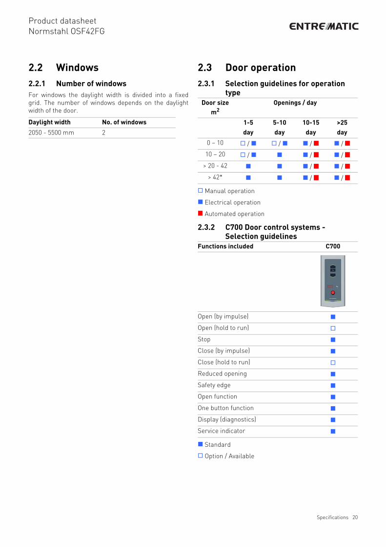
2.2 Windows2.2.1 Number of windowsFor windows the daylight width is divided into a fixedgrid. The number of windows depends on the daylightwidth of the door.
2.3 Door operation2.3.1 Selection guidelines for operation
type
Manual operation
Electrical operation
Automated operation
2.3.2 C700 Door control systems - Selection guidelines
Standard
Option / Available
Daylight width No. of windows
2050 - 5500 mm 2
Door size m2
Openings / day
1-5day
5-10day
10-15day
>25day
0 – 10 / / / /
10 – 20 / / /
> 20 - 42 / /
> 42* / /
Functions included C700
Open (by impulse)
Open (hold to run)
Stop
Close (by impulse)
Close (hold to run)
Reduced opening
Safety edge
Open function
One button function
Display (diagnostics)
Service indicator
Specifications 20

Product datasheetNormstahl OSF42FG
2.3.3 C700 Door control systems - Selection guidelines for automation
The “Automation D-kits“ are packages of commoncombinations. These kits can also be supplemented by“additions to D-kits“.
Standard
Option / Available
The following options can be individually selected to addfunctionality to the control unit.
Standard
Option / Available
Automation D-kits D1 D2 D3 D4 D5 D6
Interlocking
Magnetic loop
Traffic lights -
Green + Red
Warning lights - Red
Additions to D-kits
Warning lights – Green
Traffic lights -
Green + Red
Relay box
Radar
Functions optional C700
Complete kits
Automation D-kits
Basic control functions
Interlocking
External control functions
External pushb. box
Pull-rope switch
Remote controlopen/stop/close
Remote control
1-button function
Automatic control functions
Automatic closing
Photocell open door
Safety functions
Safety photocell (1 or 2)
French safety logic
Additional functions
UPS Battery backup
Relay box
Specifications 21

Product datasheetNormstahl OSF42FG
3. CEN Performance3.1 Lifetime expectation• 50.000 door cycles or 10 years (in a normal industrial environment) 100.000 optional.• Springs: 20.000 door cycles
3.2 Resistance to windload
Door size 4000 x 3450 mm
3.3 Resistance to water penetration
EN12424
Test result Class 3 (≤DLW 3300mm)
Class 2 (>DLW 3300mm)
Class Pressure Pa (N/m2) Specification
0 - No performance determined
1 300
2 450
3 700
4 1000
5 > 1000 Exceptional : Agreement between manufacturer and supplier
EN12425
Test result Class 3 (no passdoor)
Class Pressure Pa (N/m2) Specification
0 - No performance determined
1 30 Waterspray for 15 minutes
2 50 Waterspray for 20 minutes
3 > 50 Exceptional : Agreement between manufacturer and supplier
CEN Performance 22
Product datasheetNormstahl OSF42FG
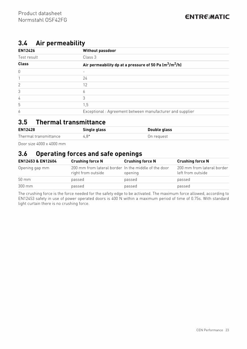
3.4 Air permeability
3.5 Thermal transmittance
Door size 4000 x 4000 mm
3.6 Operating forces and safe openings
The crushing force is the force needed for the safety edge to be activated. The maximum force allowed, according toEN12453 safety in use of power operated doors is 400 N within a maximum period of time of 0.75s. With standardlight curtain there is no crushing force.
EN12426 Without passdoor
Test result Class 3
Class Air permeability dp at a pressure of 50 Pa (m3/m2/h)
0 -
1 24
2 12
3 6
4 3
5 1,5
6 Exceptional : Agreement between manufacturer and supplier
EN12428 Single glass Double glass
Thermal transmittance 4,8* On request
EN12453 & EN12604 Crushing force N Crushing force N Crushing force N
Opening gap mm 200 mm from lateral border right from outside
In the middle of the door opening
200 mm from lateral border left from outside
50 mm passed passed passed
300 mm passed passed passed
CEN Performance 23

Product datasheetNormstahl OSF42FG
4. Building and space requirements4.1 Building preparations4.1.1 Installation preparationsThe Normstahl OSF42FG industrial sectional door is shipped in parts and installed on-site. All necessary installationmaterial is included. For every track type Normstahl offers specific installation kits to position the door in thebuilding facade.
4.1.2 Electrical preparationsThe manually operated door needs no electrical supply.
For an electrically operated door, the following environment criteria and electrical supplies are required for theoperator to function properly:
1) Steel2) Wood3) Brick & Concrete
IDO7 IDO7 HD IDO7 2H
Voltage supply: +/- 10% 230V AC
1-phase 50/60Hz
230V AC
1-phase 50/60Hz
230V AC
1-phase 50/60Hz
Power: 0,37 kW 0,6 kW 0,37 kW
Degree of protection: IP65/IP55,
excl. connector IP 44
IP65/IP55,
excl. connector IP 44
IP65/IP55,
excl. connector IP 44
Opening/Closing speed: 0,25 m/s 0,18 m/s 0,5 m/s opening
0,25 m/s closing
Allowed door weight, max.: 400 kg 800 kg 250 kg
Temperature working range: -20 °C to +55 °C -20 °C to +55 °C -20 °C to +55 °C
Operating factor: ED = 30%
S3 10 min. intermittent
ED = 30%
S3 10 min. intermittent
ED = 30%
S3 10 min. intermittent
Mounting preparations: When installing on the wall, an extra attachment angle is required
Building and space requirements 24

Product datasheetNormstahl OSF42FG
4.2 Space requirements
The grey marked area in the illustrations shows the free space required by door movement. Extra spacerequirements for electrically operated doors are stated in the operator specifications. Extra space requirements forpassdoors are stated in the passdoor specifications.
DLH = Daylight Height The height of the clear opening
DLW = Daylight Width The width of the clear opening
D = Depth The space between the inner side of the wall and the end of the horizontal track construction
h = Excess height The extra space required above the daylight height.
SL = Side space Left The space required for tracks beside the daylight width.
SR = Side space Right The space required for tracks beside the daylight width.
Building and space requirements 25

Product datasheetNormstahl OSF42FG
4.2.1 Space requirements SL
Side and top view:
DLW ≤ 5500 mm
DLH ≤ 4250 mm
h 485 mm (if DLH ≤ 4500 mm)
510 mm (if DLH > 4500 mm)
SL/SR 132 mm Manual, 212 mm Hoist-T, 278 mm Hoist-U, 319 mm Operator, 362 mm Operator+Hoist
D DLH + 600 mm
Building and space requirements 26

Product datasheetNormstahl OSF42FG
4.2.2 Space requirements SLLh 400 mm
475 mm (with center operator)
SL/SR 132 mm Manual,
212 mm Hoist-D/T, 278 mm Hoist-U,
270 mm Operator, 310 mm Operator+Hoist
(with outer support bearing + 45 mm)
D DLH + 900 mm
DLW / DLH ≤ 5500 mm / ≤ 4250 mm
For details see the specific building preparation drawings
Side view
Top view
Building and space requirements 27

Product datasheetNormstahl OSF42FG
4.2.3 Space requirements HL
Side and top view:
DLW ≤ 5500 mm
DLH ≤ 4250 mm
h HL+320 mm (if HL ≤ 3400 mm)
HL+370 mm (if HL > 3400 mm)
HL+400 mm (with center operator)
SL/SR 132 mm Manual, 212 mm Hoist-T, 278 mm Hoist-U, 319 mm Operator, 362 mm Operator+Hoist
D DLH - HL + 800 mm
Building and space requirements 28

Product datasheetNormstahl OSF42FG
4.2.4 Space requirements HHL
** SL/SR at the beam168 mm in case of an outer support bearing
DLW ≤ 5500 mm
DLH ≤ 4250 mm
h HL+220 mm (if HL ≤ 3400 mm)
HL+270 mm (if HL > 3400 mm)
SL/SR** 132 mm Manual, 228 mm Hoist-T, 278 mm Hoist-U, 280 mm Operator, 310 mm Operator+Hoist
D DLH - HL + 1100 mm
Side view
Top view
Building and space requirements 29

Product datasheetNormstahl OSF42FG
4.2.5 Space requirements LL
Side and top view
DLW ≤ 5500 mm
DLH ≤ 4250 mm
h* 265 mm (if ≤ 250 kg)
300 mm (if > 250 kg)
SL/SR 132 mm Manual, 228 mm Hoist-T, 278 mm Hoist-U, 280 mm Operator, 310 mm Operator+Hoist
D DLH + 1100 mm
Building and space requirements 30

Product datasheetNormstahl OSF42FG
4.2.6 Space requirements VLDLW ≤ 5500 mm
DLH ≤ 4250 mm
h DLH + 400 mm
SL/SR 116 mm Manual, 215 mm Hoist-T, 278 mm Hoist-U, 322 mm Operator, 375 mm Operator+Hoist
D 525 mm
Building and space requirements 31

Product datasheetNormstahl OSF42FG
4.2.7 Space requirements Door operators
4.2.7.1 Chain hoist Space requirements
4.2.7.2 IDO7 (HD) Installation locations
Location of IDO7 / IDO7HD operator
Location Extra space requirements (mm).
T-hoist U-hoist
Left/right 100 200
380
180
1500
320
002023
300
051
023
051
003
140DLW
140
DLH
Building and space requirements 32

Product datasheetNormstahl OSF42FG
Index
AAccess and automation ................16Additional functions .....................18Air permeability ............................23Automatic closing ........................17Automatic control functions .........17
B
Balancing system .........................13Basic control functions ................16Bottom seal ....................................8Building and space requirements 24Building preparations ..................24
C
C700 Door control system ............15C700 Door control systems - Selection guidelines ....................................20C700 Door control systems - Selection guidelines for automation ............21Cable break device (CBD) .............13CEN Performance ........................22Chain hoist ...................................14Chain hoist Space requirements ..32Colors ............................................7Construction ..................................7Copyright and Disclaimer Notice ...2
D
Daylight width and daylight height 19Description .....................................6Dimensions ..................................19Door leaf ........................................7Door operation .............................20
E
Electrical operation ......................14Electrical preparations .................24External control functions ............16External push button box .............16
F
Features .........................................3Fixed sections ................................9
G
General ................................... 6, 10
H
Handle ............................................8HHL - High lift with spring package at the end of the horizontal track .....11High Lift .......................................11
I
IDO7 (HD) Installation locations ...32IDO7 Operator ..............................15IDO7 Operator - C700 Door control system .........................................15Installation preparations ..............24Interlocking ..................................16
L
Lifetime expectation .....................22Lock bolt ........................................8Locks .............................................8Low Lift ........................................12
M
Magnetic loop ...............................17Material ..........................................7
N
Number of windows .....................20
O
Operating forces and safe openings 23Operating system .........................14Optional colors * ............................7Options ...........................................6
P
Performance ..................................3Photocell open door .....................17Pull-down rope ............................14Pull-rope switch ...........................16
R
Radar .......................................... 17Reduced opening ......................... 16Relay box ..................................... 18Remote control ........................... 16Resistance to water penetration . 22Resistance to windload ............... 22
S
SA/SH ............................................ 9Safety devices .............................. 13Safety edge .................................. 17Safety functions ........................... 17Safety photocells 1-channel ........ 17Safety photocells 2-channel ........ 17Seals ............................................. 7Section sizes ............................... 19Selection guidelines for operation type..................................................... 20Side seal ........................................ 7Space requirements .................... 25Space requirements Door operators32Space requirements HHL ............ 29Space requirements HL .............. 28Space requirements LL ............... 30Space requirements SL ............... 26Space requirements SLL ............. 27Space requirements VL ............... 31Special track sets ........................ 12Specifications .............................. 19Spring break device ..................... 13Standard ....................................... 6Standard colors ............................. 7Standard Lift ............................... 10Standard Low Lift ........................ 10
T
Technical facts .............................. 3Thermal transmittance ............... 23Top seal ......................................... 7Track sets ................................... 10Traffic lights - Red & Green ........ 18Types of operation ....................... 14
33

Product datasheetNormstahl OSF42FG
U
UPS battery backup .....................18
V
Vertical cross-section ..................19Vertical Lift ...................................12
W
Warning lights - Green .................18Warning lights - Red ....................17Wind reinforcement truss ..............8Windows .................................. 9, 20
34

Product datasheetNormstahl OSF42FG
35

www.normstahl.com