Embed Size (px)
Citation preview
NORTEC AIRFOG systems use the nozzle humidification
technology of injecting droplets of cold water directly into the
air. This method of humidification has the following
advantages over steam humidification:
A) Lower frequency of maintenance.
B) Systems are mainly mechanical (water pipes and airpressure) with only a 24 VAC power requirement inthe control panel.
C) A “no cost” air cooling benefit due to latent heat ofvaporization extracting heat from the air.
D) Maintenance is primarily focused on keeping the aircompressor operational.
E) Change of components is fast and requires minimalsystem disassembly.
This manual is intended to be a working guide when designing
a NORTEC AIRFOG nozzle project. For details on a specific project be sure to consult your local Condair factory trained representative.
� NORTEC AIRFOG FAMILY OF PRODUCTS
Condair manufactures NORTEC AIRFOG products in two groups. The first group is modular systems, that require
engineering design and component assembly while the second
group is packaged. Both groups require connection to electrical
power, water, and compressed air.
The modular systems group:
• Nortec AFE (AIRFOG Economical) Systems usesubsonic air flow and is commonly used in space.
The packaged group consists of two families of humidifiers:
• Nortec AFE Mini Systems are wall mounted with 1 or2 nozzles, and accept potable, RO, and DI water types.
• Nortec AFE OCTO Systems are either ceilingmounted with spray from two sides (dualconfiguration) of a rectangular case using 4, 6 or 8AFE nozzles, or as wall
mounted with spray from one side (single configuration)using 3 or 4 Nortec AFE nozzles. Nortec AFE OCTO systems are available with or without a Nortec AFE control panel built into the case. Nortec AFE OCTO systems are available for use with normal tap water,reverse osmosis, or deionized (DI) water.
NORTEC AIRFOG products all require water and air feed lines to be piped to each system. With the modular system this piping
requires more care when sizing the system. This manual will help
in the selection of the correct system and the necessary
components for that system.
� NORTEC AFE SYSTEM
PRINCIPLE OF OPERATION
The Nortec AFE nozzle uses air flow (based on Bernoulli principle) to siphon water out of zero psig water distribution
pipes. Increases in air velocity (by increasing air pressure) will
increase the vacuum pressure and hence increase the amount of
water that is siphoned into the nozzle. As the water exits the
nozzle it is broken down into a fine mist by a shearing action.
Increases in air supply pressure also means that the exiting mixed
flow is at a higher velocity.
Since Nortec AFE nozzle systems use a zero psig water pressure feed network, the water feed system and nozzles must be
horizontal and at the same height as the water pressure regulator
- 1 -Pri
nte
din
Can
ada
NORTEC AIRFOG - COMPRESSED
AIR NOZZLE ENGINEERING MANUAL
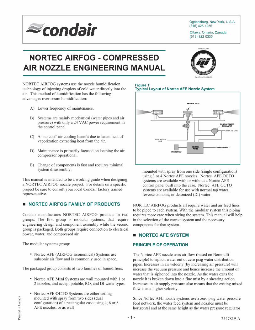
Figure 1Typical Layout of Nortec AFE Nozzle System
2547819-A
Ogdensburg, New York, U.S.A.(315) 425-1255
Ottawa, Ontario, Canada(613) 822-0335

- 2 -
(vacuum valve). Valleys or dips in vacuum valve altitude will
adversely affect performance and in extreme cases will
prevent the nozzles from producing any output. If obstructions
prevent straight level piping, the water and air network
delivery pipes must be routed under the obstruction. It is vital
that the water pipes, downstream of the vacuum valve, never
be elevated higher than the nozzles. The vacuum valve must
always be at the same height as the nozzles.
ABSORPTION DISTANCE
Injection of water droplets from a nozzle into still air will
require a certain amount of time to evaporate. The time for this
vaporization can be converted to a distance depending on the
velocity of injection into still air. The absorption distance will
increase with the speed of the supply air. If absorption is not
completed and the droplets hit solid objects like machines,
lights, piping and duct work, they will moisten that surface. To
avoid water damage, it is important to allow adequate distance
for water to be absorbed.
ADIABATIC COOLING
There are no heating elements in any of Condair's NORTEC AIRFOG humidifiers. Water is injected directly into the air at
the temperature it is supplied. As the droplets evaporate, they
extract the required latent heat of vaporization from the
surrounding air which causes the temperature of the air todecrease. This can be a significant energy saving technique insituations where mechanical cooling would otherwise be
required. Since humidification is most often required when the
exterior atmospheric temperature is below room temperature,
there is a necessity to warm the air either prior to addition of
the water droplets or after absorption of the droplets into the
air. It is recommended to add the moisture after the air isheated as this dramatically reduces the time and distance taken
for the water droplets to evaporate.
Addition of water to the air will cool the air as the droplets will
extract the energy (Latent Heat of Vaporization) necessary toconvert them from liquid form to vapor. Heat will be extracted
at the rate of approximately 1075 BTU’s/pound of water. For
example, the heat loss of 850 lbs/hr is:
850 x 1075 = 913,750 BTU’s per hour
which would have to be added by the heating system. Of
course, additional heat will also be required to heat the
incoming fresh air. Without additional heat being supplied by
heaters, rotating machines, people, large electronics
dissipating heat, etc., the bulk air temperature will drop
causing the RH to increase until either the control system turns
the system off or the dew point is reached and the water will
not be absorbed.
COMPRESSED AIR
NORTEC AIRFOG systems use compressed air as the control
fluid. Compressed air is provided by a compressor (supplied
by others) or series of compressors. The modular approach tothe NORTEC AIRFOG systems permit the designer toconsider the cost implications of using multiple smaller
horsepower compressors rather than one very large
compressor and moving the compressed air over great
distances. By using a multiple compressor design solution,
system reliability is increased, maintenance is possible without
shutting down all zones, and capital cost is often reduced.
It is recommended that air free of oil and moisture (control
quality air) be used with NORTEC AIRFOG systems. All air compressors will produce moisture which must be removed
using a refrigerated air dryer. Excessive amounts of water inthe air lines will reduce nozzle performance, and in extreme
cases will prevent the nozzle from operating. Oil must also be
removed from the compressed air through the use of oil
removal filters.
Air pressure loss can be managed by reduction in the air pipe
length, elimination of unnecessary elbows, valves and flow
restrictions, increase in the diameter of the primary delivery
pipe to the zones and elimination of leaks.
AIR CONSUMPTION
In order to properly size the air compressor, a worst case air
consumption analysis is required.
The amount of compressed air required in Standard Cubic Feet
per Minute (scfm) is calculated by multiplying the number of
nozzles loading this compressor by the rated air consumption
for that nozzle design. The Nortec AFE nozzle rated air consumption is 1.8 scfm (0.85 L/s) at 70 psig (483 kPa). For
example, the required air volume for 64 nozzles is:
1.8 x 64 = 115.2 scfm (54.4 L/s)
The required compressor horsepower (hp) can be estimated by
dividing the air volume (scfm) by 4.
115.2/4 = 28.8 hp.
If the air delivery load on the compressor requires a 100%
duty cycle to meet the system requirements, then many

- 3 -
compressors will soon overheat and fail as they are designed
for a very low duty cycle. It is recommended that at least a50% factor of safety be applied to this horsepower calculation.
In this example at least a 45 hp compressor should be used toreduce operating time and maintenance. Follow the
compressor manufacturers sizing and duty recommendations.
The compressor air quantity delivery capacity should be inexcess of the required 115.2 scfm (54.4 L/s) by a factor of
about 50% as well. Thus, the 45 hp air compressor should be
able to deliver about 180 scfm (8.5 L/s) at 90 psig (621 kPa)
or higher. Compressors that produce air above 150 psig (1035
kPa) must have their pressure reduced to no more than 150
psig (1035 kPa).
The three most popular types of compressors available are
reciprocating, rotary screw and centrifugal designs. Of these
three types, rotary screw designs are recommended as they
come in a packaged system with an air dryer and air cooler,
are designed for continuous operation as well as being very
energy efficient, quiet and generating low vibrations.
Industrial quality (as opposed to consumer quality sold at
popular retail automotive and hardware stores) are
recommended for prolonged life and low maintenance.
NORTEC AFE NOZZLE
Nortec AFE nozzles are commonly used in space. Nozzles can all be pointing in one direction if wall mounted or they can be
arranged to point in any direction if the system is suspended
from the ceiling. Horizontal spacing between nozzles is the
designer's choice, however it is recommended that nozzles be
arranged such that the spray patterns do not intersect, refer toFigure 3. The spray pattern into still air is an expanding three
dimensional cone with its apex at the nozzle orifice and
growing linearly to a 4 foot (1.2 m) diameter when 15 feet (4.5
m) away.
A fail-safe feature of the Nortec AFE nozzles is that they will automatically close the output orifice against water egress ifthe air pressure supplied to them is less than 15 psig (103.5kPa).
The Nortec AFE nozzle will deliver a maximum of 15 lbs (6.8 kg) of water per hour. Figure 2 Nortec AFE Nozzle Performance, illustrates the performance of a Nortec AFE nozzle through its design range. Pressures in excess of 70 psig
(483 kPa) will not improve water throughout and are not
recommended. See page 12 for component specifications.
NORTEC AFE NOZZLE ELEVATION AND CAPACITY
The spray pattern from the Nortec AFE nozzle will fall slightly due to the cooling effect created as the water is evaporated.
The nozzle can be operated at higher outputs when mounted at
an elevation high above the floor, machinery and stored goods.
CONTROL PANEL
Condair's NORTEC AIRFOG systems use varying air pressure to operate flow regulation valves in both the water
and air supplies to the nozzles. The panel requires an
unregulated supply off the main air supply at
90 psig (621 kPa). Figure 4 AFE Control Panel, illustrates
the panel and the interfaces to it.
0
2
6
8
10
12
14
16
4
0 10 20 30 40 50 60 70 80 90
68.9 137.9 206.8 275.8 344.7 413.7 482.7 551.6 620.5
0.9
1.8
2.7
3.6
4.5
5.4
6.3
7.2
OU
TP
UT
/N
OZ
ZLE
AIR PRESSURE
Kg/h
r
Lbs/h
r
psi
kPa
2.0
1.8
1.6
1.4
1.2
1.0
0.8
0.6
0.4
0.2
CF
M
L/
M
CAPACITY OUTPUT / NOZZLE
5.7
11.3
17.0
23.1
29.0
34.7
40.5
46.3
52.1
57.9
The capacity of the nozzles can be easily adjusted by
regulating the air pressure at the control panel, and by
adjusting the thumb wheel on the vacuum valve.
Figure 2NORTEC AFE Nozzle Performance
15 ft (4.5 m)
48"
1219.2
mm
Figure 3Typical NORTEC AFE Spray Pattern

Interfaces to the Control Panel are:
• Low voltage inlet24 Vac power input (transformer converting 110 Vac to24 Vac is supplied by CONDAIR). See page 12 forcomponent specification.
• Control wiring inputOn/Off Humidistat input (uses terminals 1 and 2 on theterminal board inside the Control Panel).
• Pilot inletMain air pressure input at 90 psig (621 kPa) branchedoff the air supply line upstream of the Air Regulator.
• Pilot outputControlling air pressure to the Air Regulator andVacuum Valve.
• The Control Panel is not limited by the number ofnozzles or zones under its command.
Figure 5 Typical Nozzle Layout, provides a sketch of a typical
configuration and inter-connectivity of these components. This
sketch is only intended to illustrate the various components
used with the NORTEC AIRFOG AFE system and is not intended as how all system must be installed. The layout and
configuration of the components will vary based on limitation
and restrictions from each application. The designer should
become familiar with each component of the system and how
it is used and connected within the overall system.
Understanding the various components will aid in the systemdesign.
NORTEC AIRFOG control panels are available in both On/Off and modulating versions. Modulating panels are used insituations when tight humidity control is required. The On/Off
controls are more suited to situations when humidity isrequired, but maintaining tight tolerances are not a priority.
- 4 -
Pilot Outlet
Pilot Inlet(Main Air)
ControlWiringInput
On/Off
Switch
GreenLighton/off
YellowLightHumidifing
PressureRegulator
Lock
PilotPressureGauge
Note: If more than four zones are operated using one Control
Panel, or if the Control Panel is more than 200 feet away (61
m) from the vacuum valve, the designer is asked to refer topage 12 for component specification.
Figure 4NORTEC AFE Control Panel

� NORTEC AFE DESIGN CONSIDERATIONS
COMPONENTS
The basic required components of a Condair single zone NORTEC AFE humidification system are:
• Control Panel (On/Off or Modulating)
• Vacuum Valve (main water feed)
• Pilot Operated Air Regulator (main air feed)
• Nortec AFE Nozzles
• 24 volt (AC) transformer
• 1/2 inch copper pipe for the water and air distributionnetworks to the nozzles (supplied by others)
• 1/4 inch plastic tube for the command pressure lines
• 1/2 inch copper pipe for the air distribution network tothe nozzles (supplied by others)
• Air Compressor - 90 psig (621 kPa) minimum(supplied by others)
• Mounting hardware (nuts, bolts, nails, etc.) (notsupplied by Condair)
Optional equipment available from Condair include:
• Humidistat
• Primary Air Control Section
• Primary Water Control Section
• Nozzle Support Bracket
• Saddle Clamp and Adapter
• Modulation Control Adapter
• Modulation Control Package
• High Limit Humidistat
- 5 -
Figure 5Typical Nozzle Layout
Primary WaterPressure ControlSection
Main Water1 2/ Copper PipingType"L" or RigidPlastic Piping(by others)
"
1 4/ PolytubeControl Lines
"
Humidistat
24 Vac Transformer
Control Panel
Main Air
Primary AirPressure ControlSection
Pilot OperatedAir Regulator
Vacuum ValveAir Water

VACUUM VALVE (WATER PRESSURE REDUCTION)
Air pressure from the Control Panel opens the water safety
valve permitting water to enter the Vacuum Valve which
controls the water feed to the nozzles. Figure 6 Operation of
Vacuum Valve, explains the operation of this water regulator.
The water flow rate through this valve is limited to 28.8 gph
(110.8 l/hr) which limits the number of Nortec AFE nozzles it supplies to 16. If the analysis of section 3.0 indicates anecessity to have more than 16 nozzles, then the system must
be broken into zones using multiples of 16 (or less) nozzles
with each zone controlled by its own Vacuum Valve. One
Control Panel can control multiple zones by branching off of
the single Control Panel air pilot output.
The Vacuum Valve assembly has three sub-components. As
illustrated in Figure 7 Vacuum Valve and Interfaces. First, the
safety valve interfaces directly with the primary water supply;
opening and closing on command from the Control Panel.
Lost pilot air pressure (below 10 psi / 69 kPa) will
automatically close this valve to prevent water from
proceeding beyond this point. In series with, and downstream
of the safety valve, is the water regulator used as the first stage
of water pressure reduction. The water regulator reduces the
raw water pressure to a range between 5 and 10 psig
(34.5-69.0 kPa). This is set manually at time of installation,
however system performance is not sensitive to the exact
setting as long as the pressure is within this range.
The second stage of water pressure reduction is the vacuum
diaphragm which drops the pressure to that of the room.
Output is through one exit port on each of its two sides. This
permits the nozzle to draw water from the supply as it isrequired rather than having pressure force it into the nozzle.
This siphoning action of the nozzle is controlled by the Pilot
Operated Air Regulator.
On top of the Vacuum Valve is a thumb wheel adjustment for
adjustment of the NORTEC AIRFOG droplet size. The adjustment changes the availability of water to the nozzles.
Thus a reduction in available water for the same air
consumption results in smaller droplets and a finer spray. This
adjustment can be used to reduce the water throughput if there
is a problem with water droplets reaching the floor. See page
12 for component specification.
- 6 -
Outlet Connection
Plastic / O.D.
Tube Connection
3 8"
Pressure Gauge
Water Safety Valve
Water Inlet
Connection
/ O.D. Tube3 8"
Wall Bracket with
/ Mounting Holes1 4"
Pressure Regulator
Set to 5-7 PSIG
Fine AdjustmentKnob
View from above showing FineAdjustment Knob and Wall Bracket
Pilot InletConnection1/4” O.D. Tube(from control panel)
Air Compressor
Water
As the pressurised waterenters the VV chamber itpushes up on thediaphram closing thewater valve.
During normal operationthe vacuum valve willcycle between the openand closed state.
Air Compressor
Water
Compressed air exitsthe nozzles creating avacuum on the waterside. The negativepressure pulls the VVdiaphragm down,opening the watervalve.
Figure 6Operation of Vacuum Valve
Figure 7Vacuum Valve and Interfaces
Outlet Port
(to NORTEC AFE nozzles)
Pilot OperatedAir Regulator
Pilot Line(from control panel)
Inlet Port(main air)
Figure 8Pilot Operated Air Regulator

PILOT OPERATED AIR REGULATOR
The Pilot Operated Air Regulator controls the air feed to the
nozzles and is illustrated in Figure 8 Pilot Operated Air
Regulator. This regulator is an analog flow controller; the
greater the commanded air pressure, the greater the air
pressure fed to the nozzle supply network. This means that
the Control Panel is able to command a proportional opening
of the Air Regulator simply by varying the command pressure.
There is a linear 1:1 relationship between the command
pressure and the pressure drop. A pilot air pressure of 25 psig
(172.5 kPa) will drive the Air Regulator to have an output of
25 psig (172.5 kPa).
The three ports on the Pilot Operated Air Regulator are the
pilot air pressure input from the control panel, the primary air
supply input feed and the output air feed to the nozzles.
There are no manual adjustments needed or possible. See
page 12 for component specifications.
� AIR SUPPLY
Air must be free of oil and other contaminants through the use
of oil removal and other filters. Compressor selection (90 psig
(621 kPa) at the calculated air flow rate as a minimum) is a
critical consideration. The delivered air must also be free of
moisture in order to maintain the performance of the nozzles.
During compression, moisture is always produced and must be
removed by refrigerated air drying. Moisture in the air pipes
has the potential to not only reduce nozzle performance but
the impact of excessive quantities could be sufficient toprevent the nozzle from delivering any water.
AIR SUPPLY NETWORK
The flow of compressed air in pipes causes friction and results
in pressure losses. The ideal NORTEC AIRFOG air delivery system would be designed to have less than 2 psig (13.8 kPa)
pressure loss. To reduce the line pressure losses the following
guidelines are useful:
• Reduce the distance the air must travel.
• Reduce the friction through the pipes by increasing thepipe size and eliminating unnecessary elbows, valvesand other flow restrictions.
• Reduce the flow rate of air through the system.
• Minimize the drop in pressure across systemcomponents.
- 7 -
Applied Pressure[PSIG]
Nominal Standard Pipe Size
1/8" 1/4" 3/8" ½" 3/4" 1" 1-1/4" 1-1/2" 2" 2-1/2" 3"
5 0.5(0.2)
1.2(0.6)
2.7(1.3)
4.9(2.3)
6.0(3.1)
13(6.1)
27(12.7)
40(18.9)
80(37.8)
135(63.7)
240(113.3)
10 0.8(0.4)
1.7(0.8)
3.9(1.8)
7.7(3.6)
11.0(5.2)
21(9.9)
44(20.8)
64(30.2)
125(59.0)
200(94.4)
370(174.6)
20 1.3(0.6)
3.0(1.4)
6.6(3.1)
13.0(6.1)
18.5(837)
35(16.5)
75(35.4)
110(51.9)
215(101.5)
350(165.2)
600(283.2)
40 2.5(1.2)
5.5(2.6)
12.0(5.7)
23.0(10.9)
34.0(16.0)
62(29.3)
135(63.7)
200(94.4)
385(181.7)
640(302.1)
1100(519.2)
60 3.5(1.7)
8.0(3.8)
18.0(8.5)
34.0(16.0)
50.0(23.6)
93(43.9)
195(92.0)
290(136.9)
560(264.3)
900(424.8)
1600(755.2)
80 4.7(2.2)
10.5(5.0)
23.0(10.9)
44.0(20.8)
65.0(30.7)
120(56.6)
255(120.4)
380(179.4)
720(339.8)
1200(566.4)
2100(991.2)
100 5.8(2.7)
13.0(6.1)
29.0(13.7)
54.0(25.5)
80.0(37.8)
150(70.8)
315(148.7)
470(221.8)
900(424.8)
1450(684.4)
2600(1227.2)
Table 1Air Flow Rates For Various Pipe Diameters Under Pressure
Note: Flow rates - standard cubic feet/min (Liters/sec). Metric conversion = CFM x 0.472 = Liters/second.

• Eliminate leaks. It includes a shut off valve, primary air regulator (0 to 100
psig) (0-690 kPa) and a pressure gauge, and a filter (optional).
It is threaded to connect with ½” NPT female thread. See
page 12 for component specifications.
� WATER SUPPLY
The NORTEC AIRFOG nozzles work with potable, RO, and De-ionized water. Please note that mineral content in potable
water will vary according to geographic location. This mineral
content will precipitate out as a fine dust. In many buildings,
this is not a major concern. It is recommended not to use
water from a sodium softener, as it will cause excessivedusting.
In the printing and electronics manufacturing sectors, dusting
is considered to be a major concern. Water for these
applications may be processed through a Reverse Osmosis
(RO) membrane to remove the minerals and obtain very high
water purity. The piping may have to be upgraded to acompatible plastic or stainless steel. The storage tank and
associated water plumbing is provided by the building owner.
For ultra clean rooms (spacecraft assembly, electronics
assembly, printing plate fabrication, etc.) de-ionized (DI)
water will be required. This process will require selection of acompatible plastic or stainless steel pipe. Water storage and
pumping will also be required. See page 12 for componentspecifications.
WATER SUPPLY NETWORK
The water supply network feeding the nozzles is normally
comprised of ½ inch type L hard copper, stainless steel or
heavy wall rigid plastic pipe available from plumbing
suppliers. Standard plumbing joining techniques are used infabrication.
Selection of the pipe material is the designer's choice but this
is often determined by cost and the aggressiveness of thewater.
PRIMARY WATER PRESSURE CONTROL SECTION(OPTIONAL)
This hardware is used to control water pressure and regulate
the water flow from the supply system to zone Vacuum
Valve(s). As shown in Figure 10 Primary Water Pressure
Control Section, it consists of break away unions, a shut off
ball valve, a water strainer and a water pressure regulator. It
will permit isolation shut off to a zone for maintenance
activities while other zones remain operational. The
maximum flow rate capacity is 3 gallons per minute (0.19
- 8 -
1/2" FNPT 1/4 Turn Shut Off Valve
1/2" NPT Brass Union
1/2" NPTBrass Union
Air Regulator
Filter (optional)
The air supply network is normally comprised of ½ inch type
L hard copper pipe available from plumbing suppliers.
Standard plumbing joining techniques are used in fabrication.
Use Table 1 Air Flow Rates, to determine the appropriate pipe
size for a given nozzle air requirement and pressure. As an
example, a 60 nozzle system in six zones of 10 nozzles
requires 18 scfm (8.5 L/s) air per zone for a total of (18 x 6)
108 scfm (8.5 L/s) at 90 psig (621 kPa). The recommended
pipe size is 1" diameter for 80 psig (552 kPa) and 120 scfm
(56.6 L/s). Pipe lengths longer than 100 ft should consider
larger diameters.
Reduction to ½” diameter pipe can be made at the pilot
operated air regulator as pressure losses will not be excessive
over these shorter lengths.
PILOT AIR PIPING
The pilot air pressure line from the Control Panel to the Pilot
Air Regulator and the Vacuum Valve uses 1/4” plastic tube.
The supply air pressure line to the Control Panel comes from
the unregulated air supply via 1/4” plastic tube as illustrated
in Figure 5 Typical Nozzle Layout.
PRIMARY AIR CONTROL SECTION (OPTIONAL)
This hardware, used to control and regulate the air flow from
the compressor to the air regulator, is illustrated in Figure 9Primary Air Control Section.
It can be used to regulate air output pressure to 70 psig (483
kPa) and to attenuate pressure spikes that may result from the
compressor. This hardware is limited to supplying 16
NORTEC AFE nozzles.
Figure 9Primary Air Control Section

L/s). This capacity can provide water to many nozzles but it isrecommended that not more than 4 zones be controlled by asingle Primary Water Control Section. Not suitable for DIwater.
It is threaded for NPT female pipe thread.
WALL SUPPORT BRACKETS (OPTIONAL)
These brackets as shown in Figure 11 Condair Wall Support Bracket, have been specifically designed to permit easy
mounting of a Nortec AFE nozzle to a wall, column or pillar. The bracket provides for +/- 5 inches (127 mm) from
centerline vertical adjustment to provide the installers with an
easy method to adjust all nozzles in a zone to be equidistant
from the floor. Since the nozzles use a siphoning action in the
water distribution network at 0 psig, it is vital that there be no
vertical gradients in this network. The bracket also provides aconvenient place to rest water and air distribution piping.
Ceiling mounting brackets are also available as shown inFigure 12 Ceiling Mounting Hardware.
MOUNTING HARDWARE PACKAGES
Each package consists of two saddle clamps and two feet of
tubing to connect the air distribution pipe and the water
distribution pipe to a nozzle. Not suitable for DI water.
- 9 -
Polytube
Nortec AFE Nozzle
Wall Support Bracket
Polytube
Saddle Clamp
Saddle Clamp
Mounting HolesFor 1/4" Leg Bolts
Leg Bolts(supplied by others)
Figure 11Condair Wall Support Bracket
Pipe Hanger(by others)
Threaded Rod(supplied by others)
Nortec AFE Nozzle
Installation Hardware Package(includes saddle clamps,adapters and tubing)
Air Line
Water LineSupply Lines ToNozzles(by others)
Nozzle SupportBracket
Figure 12Ceiling Mounted Hardware
1/2" NPTBrass Union
1/2" NPTBrass Union
1/2" FNPT
1/2" FNPT
Brass "Y" Type1/2" NPT
Shut Off Valve
Pressure Gauge0-100 PSIG
Figure 10Primary Water Pressure Control Section

NORTEC AFE MINI systems are can be ordered with 1 or 2 nozzles, and are available in versions that are compatible with
de-ionized (DI) water. All NORTEC AFE MINI systems are configured for On/Off control.
� NORTEC AFE OCTO
DESIGN CONSIDERATIONS
NORTEC AFE OCTO systems are self contained ceiling mounted units with up to 8 Nortec AFE nozzles per system.
If you require 3 or more nozzles than an NORTEC AFE OCTO or several NORTEC AFE OCTO systems could be suitable.
Nortec AFE Octo systems are available in a variety of configurations, including versions available for de-ionized
(DI) water. 4,6 or 8 nozzles can be ordered on a NortecOCTO, spraying out of 2 sides of the enclosure.
Configurations with only 4 nozzles can be ordered with 4nozzles on one side and none on the other for
- 10 -
0 5 10 15 20 25 30
0 5 10 15 20 25 30
NORTEC OCTO c/w 8 Nozzles
NORTEC OCTO Plus c/w 8 Nozzles
easy wall mounting (as opposed to 2 nozzles per side for ceiling mounting).
Control options also vary; the Octo can be ordered with an external control panel (NORTEC AFE OCTO) for convenient remote control of the system. The base Nortec OCTO supports on/off or modulating control depending on the Nortec AFE control panel ordered. Up to 4 NORTEC AFE OCTO’s can be controlled from a single Nortec AFE control panel. See Figure 16 Four NORTEC OCTO Systems Operated From One Control Panel. The NORTEC OCTO can also be ordered with an internal control panel (NORTEC OCTO Plus). The NORTEC OCTO Plus is available in an on/off control configuration (NORTEC OCTO Plus) or a modulating control configuration (NORTEC OCTO Plus Modulation).
Complete work space humidification can be supplied by a single or a number of NORTEC OCTO systems. One control panel can control up to 4 NORTEC OCTO systems. For systems requiring only one unit of 8 or less nozzles, there is the NORTEC OCTO PLUS which comes complete with a self contained control panel. See Figure 14 NORTEC OCTO and NORTEC OCTO Plus. Multiple NORTEC OCTO systems must be broken down into sections of 4 NORTEC OCTO’s systems (maximum of 4 x 8 = 32 nozzles) with each section of 4 NORTEC OCTO’s controlled by one Control Panel. As illustrated in Figure 16 Four NORTEC OCTO Systems Operated From One Control Panel.
Each of the NORTEC OCTO systems will require its own compressed air and water supplies. Piping selection is identical to the Nortec AFE nozzle systems described earlier.
NORTEC OCTO systems should be installed with a minimum clearance to the floor of 20 feet (6.1 m).
Figure 14NORTEC OCTO and NORTEC OCTO Plus
AFE-Mini
R
Humidistat
Clean Out Plugs
Optional AirPrimary PressureRegulator
Optional WaterPrimary PressureRegulator
Shut Off Valves
24 Vac Step DownTransformer
Water feed
Air Feed
3/8" Tube Compression FittingFor Plastic Tubing
1/4" Quick Disconnect FittingFor Plastic Tubing
� NORTEC AFE MINI
DESIGN CONSIDERATIONS
For smaller applications requiring 1 or 2 nozzles, and Nortec AFE Mini system is the best choice.
These are self contained wall mounted units (one or two
nozzles only) which require a nozzle clearance of 6 feet (1.8
m) off the floor and 3 feet (0.91 m) from the ceiling.
Compressed air, water and 110 VAC need to be conveniently
located and a centrally located humidistat will be required.
Figure 13Typical Nortec MINI System

can be “T” connected to all four NORTEC OCTO systems. In this way, one Control Panel can control up to 4 NORTEC OCTO systems.
Modular Nortec AFE nozzle systems are often more economical than multiple NORTEC OCTO systems. However, advantages of using multiple NORTEC OCTO units compared to a full modular design include:
• Ease of installation
• Ease of NORTEC OCTO air and water isolation formaintenance
• Ease of access
• Prepackaged units that are ready to run.
• Saving in design time
• Fewer startup problems
- 11 -
32´9.75 m
16´4.88 m
16´4.88 m
12´3.65 m
28'8.5 m
The spray pattern for an 8 nozzle NORTEC OCTO system can extend to 16 feet (4.9 m) in each direction (4 nozzles spray in each of 2 opposite directions). Figure 15 NORTEC AFE OCTO Spray Pattern, demonstrates the spray pattern dimensions that have to be free of collision with obstacles and spray plumes from other nozzles. Nozzle point angles are adjustable in both horizontal and vertical directions. Adiabatic cooling under the spray may be significant for operating equipment and people in the vicinity and must be considered
in locating NORTEC OCTO systems.Figure 15NORTEC AFE OCTO Spray Pattern
Power Off On
R
R
A IR FOG
AFE Control
Air
OCTO 4 OCTO 3 OCTO 2 OCTO 1
Primary Water Pressure Control
Primary Air Pressure Control AIRFOGControlPanel
Pilot Air Signal
Main Air
Figure 16 Four NORTEC OCTO Systems Operated From One Control Panel, is a typical installation layout for 4 NORTEC OCTO units and a control panel. The pilot air pressure input to the control
panel is connected directly to the air pressure line (90 psig) (621 kPa)
by 1/4 inch plastic tubing. The “Pilot - Out” from the Control Panel
is the command pressure which
Figure 16Four NORTEC OCTO Systems Operated From One Control Panel

� NORTEC AIRFOG SYSTEM COMPONENTSPECIFICATIONS
NORTEC AFE CONTROL PANEL
• 24 VAC
• Standard configuration On/Off
• Bulkhead fittings at top of panel for ¼” plastic tube.Pilot lines only
• 4 zones of 16 nozzles each
• If more than 200 ft (61 m) use pilot air regulator actingas a volume booster
• More zones can be controlled with one control panelwith the use of a pilot air regulator acting as a volumebooster
• Weight 15.2 lbs (6.9 kg)
TRANSFORMER
• 110 VAC primary
• 24 VAC secondary
• 40 VA maximum
• 51 W
• Plug in style
• Screw terminals for secondary line connection
• Weight 1.6 lbs (0.72 kg)
HUMIDISTAT
• One per control panel
• Ability to switch 24 VAC at 1 amp
• On/Off style (On/Off control panels only)
• 0-10 V or 4-20 mA Demand Signal (modulating controlpanels only)
VACUUM VALVE (WATER FEED)
• One per zone feeding a maximum of 16 nozzles
• Maximum flow rate of 28.8 gph (110 L/hr)
• Inlet connection use 3/8” plastic tubing
• Outlet connections use 3/8” plastic tubing
• Mounting holes ¼”
• Weight 3.2 lbs (1.45 kg)
PILOT OPERATED AIR REGULATOR
• One per zone feeding a maximum of 16 nozzles
• Air flow rate 45 scfm (21.2 L/s)
• Inlet and outlet connection 3/8” (female) NPT
• Pilot connection ¼” (female) NPT
• Can be used as a volume booster where there are largepressure losses
NORTEC AFE NOZZLES
• Water throughput of 0 to 15 lbs/hr (6.8 kg/hr)
• Air consumption maximum of 1.8 scfm (0.85 L/s)
• Pressure range 0 to 70 psig (0-483 kPa)
• Nozzle connections ¼” plastic tube
• Mounting port thread 3/8” NC
• Weight 1.46 lbs (0.66 kg)
PRIMARY AIR CONTROL SECTION
• Maximum supply pressure 150 psig (1035 kPa)
• Adjustable pressure 0-120 psig (0-828 kPa)
• One per zone of 16 nozzles (45 scfm) (21.2 L/s)
• ½” (female) NPT port
- 12 -

• Weight 3.1 lbs (1.4 kg)
PRIMARY WATER CONTROL SECTION
• Primary pressure range 150 psig (1035 kPa)
• ½” (female) NPT ports
• The capacity is 100 gallons/hr (378 L/hr) butrecommend a limit of one for 4 zones
• Weight 4.3 lbs (1.95 kg)
� NORTEC MINI SYSTEM COMPONENT
CAPACITIES NORTEC MINI CONTROL PANEL
• Capacity 0 - 28 lbs/hr (0-12.7 kg/hr)
• 24 VAC
• On/Off configuration only
• Air connection 1/4” plastic tube
• Water connection 3/8” plastic tube
• Weight 20 lbs (9.0 kg)
NORTEC AFE NOZZLES
• See page 12.
TRANSFORMER
• See page 12.
� NORTEC OCTO SYSTEM COMPONENT CAPACITIES
NORTEC OCTO AND NORTEC OCTO PLUS UNIT
• System capacity up to 120 lbs/hr (54.5 kg/hr)
• Air connection ½” plastic or soft copper tube
• Water connection 3/8” plastic or soft copper tube
• Pilot connection ¼” plastic tube
• Weight up to 64 lbs (29 kg)
NORTEC AIRFOG CONTROL PANEL / OCTO PLUS
• 24 VAC
• On/Off configuration (NORTEC OCTO and NORTECOCTO Plus)
• Modulating Configuration (NORTEC OCTO andNORTEC OCTO Plus Modulation)
• Bulkhead fittings at top of panel for ¼” plastic tube.Pilot lines only.
• Up to 4 zones of 16 nozzles each. More zones can becontrolled with one control panel with the use of a pilotair regulator acting as a volume booster
• Weight 15.2 lbs (6.9 kg)
NORTEC AFE NOZZLES
• See page 12.
TRANSFORMER
• See page 12.
- 13 -

� SPECIFICATIONS
PART 1 - GENERAL
1.1 WORK INCLUDED
a) NORTEC AIRFOG atomizing nozzle humidifier[s]as indicated on drawing[s] and as indicated onschedule[s].
b) Complete and operable humidification system [whichmeets applicable building codes].
c) Equipment startup and project inspection by qualifiedfactory trained representative.
1.2 RELATED SECTIONS:
a) 15010 Mechanical General Requirements
b) 15[ ] Piping Installation
c) 15[ ] Control System
1.3 REFERENCES:
a) ISO 9001-2000
1.4 SUBMITTALS:
a) Submit shop drawings and product data forhumidifier[s] and control panel[s] in accordance withSection [ ] Shop Drawings, Product Data
b) Exceptions to this specification and accompanyingschedules to be noted on separate sheet [withnotation].
c) Submit operation and maintenance data forincorporation into manual specified in Section [ ]Operation and Maintenance Manual.
1.5 SCHEDULES:
a) Refer to information contained in schedule[s]attached to this specification.
b) Humidifiers to be of type, capacity, and arrangementas listed in schedule[s].
c) Include accessories listed in schedule[s] and thoseaccessories required for type of unit.
NOZZLE HUMIDIFICATION SYSTEM
NORTEC AIRFOG ATOMIZING MODEL AFE
SpecNote: Product specified below is manufactured by
Condair in ISO 9001-2000 certified facilities.
PART 2 - PRODUCTS
2.1
2.2
2.3
NORTEC AIRFOG AFE ATOMIZING NOZZLE SYSTEM USING COMPRESSED AIR TOATOMIZE WATER, DRAWN THROUGH AVACUUM VALVE AT ATMOSPHERICPRESSURE, WITHIN THE AIR STREAM.
BUILT-UP SYSTEM, FOR DIRECT SPACEAPPLICATION, REQUIRING AFE CONTROLPANEL[S], VACUUM VALVE[S], PILOTOPERATED AIR REGULATOR[S] AND AFENOZZLE[S].
SYSTEM TO BE COMPLETE WITH:
a) Operating and safety controls to ensure an automaticand fail safe system.
b) Nozzles to shut down automatically on loss of airpressure without dripping even when water pressureis maintained to system.
c) Linear output adjustment as air pressure is reduced tonozzle and continues to produce droplets no largerthan 10 microns in size as air pressure reduces.
d) Vacuum valve to provide water supply to nozzles atatmospheric pressure.
e) Pilot operated air regulator to allow variable supplyair pressure to nozzles.
f) Control panel with built-in air pressure regulator,repeat cycle timer, on/off switch, pilot light and airpressure gauge.
2.4 ATOMIZING NOZZLE TO BE:
a) Constructed of stainless steel.
- 14 -

b) Complete with air operated piston to activate plungerand pin to clean water orifice each time system cyclesoff.
c) Serviceable without removal from system.
d) Without obstructions after orifice, which may collectdust, water or foreign matter.
2.5 CONTROL PANEL TO INCLUDE:
a) NEMA 12 construction.
b) Cabinet to allow user full front access with keyedlock.
c) Compressed air regulator with gauge.
d) Adjustable repeat cycle timer, for cleaning action ofnozzle.
e) Compressed air pilot line operation only. No directwater line connections to control panel permitted.
f) On/off switch complete with pilot light.
g) Solenoid valve to shut down system on loss ofelectrical power.
h) Controls to provide safety shutdown of system for:
• Loss of air pressure.
• Loss of electric power.
i) Internal factory wiring and piping.
j) Connection for pilot tubing to pilot operated waterregulator at vacuum valve, and pilot operated airregulator.
k) External 120/24 Vac plug-in transformer for internalpower.
2.6 VACUUM VALVE TO INCLUDE:
a) Adjustable water pressure regulator.
b) Pilot operated water regulator as safety to interruptsupply water pressure when supply air pressure islost.
2.7 PERFORMANCE:
a) Water pressure: 10 psig [69 kPa] minimum.
b) Working water pressure: atmospheric.
c) Air pressure: 90 psig [621 kPa] minimum,150 psig maximum [1035 kPa].
d) Working air pressure: 0-70 psig [0-483 kPa].
e) Nozzle compressed air consumption:1.8 cfm @ 70 psig [51 L/m @ 483 kPa].
f) Nozzle mist output:14 lbs/hr @ 70 psig [6.4 kg/hr @ 483 kPa].
2.8 OPTIONAL ACCESSORIES:
a) Refer to options schedule.
- 15 -

� LIMITED WARRANTY
Condair Inc. and/or Condair Ltd. (hereinafter collectively referred to as THE COMPANY), warrant for a period of two years from date of shipment, that THE COMPANY’s manufactured and assembled products, not otherwise expressly warranted,are free from defects in material and workmanship. No warranty is made against corrosion, deterioration, or suitability of substituted materials used as a result of compliance with government regulations.
THE COMPANY’s obligations and liabilities under this warranty are limited to furnishing replacement parts to the customer,F.O.B. THE COMPANY’s factory, providing the defective part(s) is returned freight prepaid by the customer. Parts used for repairs are warranted for the balance of the term of the warranty on the original humidifier or 90 days, whichever is longer.
The warranties set forth herein are in lieu of all other warranties expressed or implied by law. No liability whatsoever shall be attached to THE COMPANY until said products have been paid for in full and then said liability shall be limited to the original purchase price for the product. Any further warranty must be in writing, signed by an officer of THE COMPANY.
THE COMPANY’s limited warranty on accessories, not of Condair’s manufacture, such as controls, humidistats, pumps,etc. is limited to the warranty of the original equipment manufacturer from date of original shipment of humidifier.
THE COMPANY makes no warranty and assumes no liability unless the equipment is installed in strict accordance with a copy of the catalog and installation manual in effect at the date of purchase and by a contractor approved by THE COMPANY to install such equipment.
THE COMPANY makes no warranty and assumes no liability whatsoever for consequential damage or damage resulting directly from misapplication, incorrect sizing or lack of proper maintenance of the equipment.
THE COMPANY retains the right to change the design, specification and performance criteria of its products without notice or obligation.