Embed Size (px)
Citation preview

www.mvr.nt.gov.au
DEPARTMENT OF TRANSPORT
NORTHERN TERRITORY
INSPECTION MANUAL
FOR
LIGHT VEHICLES
2 September 2004
Produced by
Transport Regulation and Compliance
Vehicle Standards Section
Amended 4 December 2014

This page intentionally left blank

NT Inspection Manual for Light Vehicles Effective 2 September 2004 Amended 4 December 2014
Page i
Table of Contents
Introduction ................................................................................................................... 1
About this Manual ..................................................................................................................... 2 Purpose ..................................................................................................................................... 2 Overview .................................................................................................................................... 2 How this manual will be amended ........................................................................................... 3 Amendment Schedule – (implemented from December 2014) .................................................. 3 Where to get advice .................................................................................................................. 3
Section 1 Brakes ................................................................................................... 5
1.1 Check the operation of the brake controls. ....................................................................... 6 1.2 Inspect the condition of visible brake components. ........................................................... 6 1.3 Service brake test with a decelerometer. .......................................................................... 7 TABLE 1 Service Brake Performance ..................................................... 8 1.4 Parking brake test for vehicles not designed to ADR31, ADR 35 or vehicles not fitted
with a tandem master cylinder/dual circuit brakes. ........................................................... 8 TABLE 2 Parking Brake Performance ..................................................... 9 1.5 Parking brake test for vehicles designed to ADR 31, ADR 35 or vehicles fitted with a
tandem master cylinder/dual circuit brakes. ..................................................................... 9 1.6 Brake testing with a skid-plate tester. ............................................................................... 9 1.7 Brake testing with a roller brake tester. ........................................................................... 10 TABLE 3 Minimum Brake Force............................................................. 10 TABLE 4 Maximum Brake Drag ............................................................. 10 1.8 Road testing of service brakes ....................................................................................... 11 TABLE 5 Service Brake Performance ................................................... 11
Section 2 Towing Attachments ........................................................................... 13
2.1 Visually inspect the towbar and its mounting on the vehicle body. .................................. 14
Section 3 Steering and Suspension .................................................................... 15
3.1 With the engine running, check the operation of the steering by moving the steering wheel, or, on cycle type vehicles, the handle. ................................................................ 16
3.2 Visually inspect all steering components under the bonnet and under the vehicle. ......................................................................................................................... 16
3.3 Examine the idler arm. .................................................................................................... 17 3.4 Visually inspect the suspension. ..................................................................................... 17
Section 4 Wheels and Tyres ................................................................................ 19
4.1 Visually inspect the inside and outside of each road wheel............................................. 20 4.2 Visually inspect each road tyre. ...................................................................................... 20 4.3 Measure the wheel track, where modified from standard, taking measurement from
the centre of the tyres. ................................................................................................... 21
Section 5 Body Condition .................................................................................. 23
5.1 Check the operation of all doors, door locks and latches and the bonnet lock and latches. .......................................................................................................................... 24
5.2 Visually inspect the windscreen and windows................................................................. 24 5.3 Test the light transmittance level of the windscreen, side and rear windows. .................. 25 5.4 Visually inspect body panels, chassis and subframe for dangerous protrusions and
rust. ............................................................................................................................... 26

NT Inspection Manual for Light Vehicles Effective 2 September 2004 Amended 4 December 2014
Page ii
5.5 Inspect the wheel arches/mudguards and mudflaps, with the wheels in the "straight ahead" position. ............................................................................................................. 27
5.6 Visually inspect rear vision mirrors ................................................................................. 27 5.7 Visually inspect and check the operation of the windscreen wipers and windscreen
washers. ........................................................................................................................ 27 5.8 Check the operation of the horn...................................................................................... 28 5.9 Visually inspect the front and rear number plates. .......................................................... 28 5.10 Where ADR 25 applies, check the operation of the anti-theft/steering lock. .................... 28 5.11 Where ADR15 applies, check the operation of the windscreen demister. ....................... 28 5.12 Speedometer .................................................................................................................. 29
Section 6 Seats and Seatbelts ............................................................................ 31
6.1 Check seats ................................................................................................................... 32 6.2 Check seat belts ............................................................................................................. 32 6.3 Check child restraints ..................................................................................................... 32
Section 7 Lighting ............................................................................................. 35
7.1 Visually inspect the compulsory reflectors fitted to the rear of the vehicle. ...................... 36 7.2 Visually inspect and check the operation of all lights fitted to the vehicle. ....................... 36 7.3 Visually inspect front and rear lights for the presence of tinted covers. ........................... 38 7.4 Using a headlight tester or testing screen, check the aim of the headlights. ................... 38 7.5 Visually inspect the headlights. ....................................................................................... 38
Section 8 Engine Compartment & Driveline ....................................................... 39
8.1 Visually inspect the engine, transmission and driveline, operate the transmission control............................................................................................................................ 40
8.2 Visually inspect the exhaust system. .............................................................................. 40 8.3 Where ADR 37 applies, check for the presence of a catalytic converter. ........................ 41 8.4 Visually inspect the fuel system. ..................................................................................... 41 8.5 Stationary Exhaust Noise ............................................................................................... 42 Table of Noise Limits for Cars and Car Derivatives .................................... 42
Section 9 Fuel Systems LPG/NGV/CNG ............................................................. 43
9.1 Visually inspect for the installation of a Liquid Petroleum Gas (LPG), Natural Gas Vehicle (NGV) or Compressed Natural Gas (CNG) system. .......................................... 44
Vehicles with systems installed within the Northern Territory ................... 44 9.2 Visually inspect for the presence of an approved LPG/NGV/CNG modification plate
and number plate labels. ............................................................................................... 44
Section 10 Fuel Systems Petrol/Diesel............................................................... 47
10.1 Visually inspect the fuel system. ..................................................................................... 48
Section 11 Motorcycles ...................................................................................... 49
11.1 Visually inspect the condition of the brake controls. ........................................................ 50 11.2 Check the operation of the brake controls ...................................................................... 50 11.3 Inspect the condition of visible brake components. ......................................................... 50 11.4 Check the operation of the parking brake on ADR 33 cycles fitted with side-car outfits. . 50 11.5 Visually inspect the towbar and its mounting to the frame. ............................................. 51 11.6 Visually inspect all steering components. ....................................................................... 52 11.7 Visually inspect the suspension. ..................................................................................... 53 11.8 Inspect both sides of each road wheel. ........................................................................... 55 11.9 Visually inspect each road tyre. ...................................................................................... 55 11.10 Visually inspect body panels, chassis and frame for dangerous protrusions and rust. .... 56 11.11 Inspect the mudguards. .................................................................................................. 56

NT Inspection Manual for Light Vehicles Effective 2 September 2004 Amended 4 December 2014
Page iii
11.12 Visually inspect rear vision mirror(s). .............................................................................. 56 11.13 Check the operation of the horn...................................................................................... 57 11.14 Visually inspect any exposed drive chain, belt, shaft and sprockets ............................... 57 11.15 Visually inspect the number plate(s). .............................................................................. 58 11.16 Indicators ........................................................................................................................ 58 11.16 Visually inspect the compulsory reflectors fitted to the rear of the cycle. ......................... 60 11.17 Visually inspect and check the operation of all lights fitted to the cycle. .......................... 60 11.18 Visually inspect front and rear lights for the presence of tinted covers. ........................... 61 11.19 Using a headlight tester or testing screen, check the aim of the headlight(s). ................. 61 11.20 Visually inspect the headlight(s). .................................................................................... 62 11.21 Visually inspect the engine, remote oil reservoirs, transmission and driveline................. 63 11.22 Visually inspect the fuel system. ..................................................................................... 63 11.23 Visually inspect the exhaust system. .............................................................................. 63 11.24 Stationary Exhaust Noise for Motorcycles ...................................................................... 63 Table of Noise Limits for Motorcycles ......................................................... 64
Section 12 Light Trailers & Caravans .................................................................... 65
Introduction ............................................................................................................................. 66 12.1 Mass Definitions: ............................................................................................................ 66 Aggregate Trailer Mass (ATM) ...................................................................... 66 Gross Trailer Mass (GTM) ............................................................................. 66 12.2 Trailer Braking requirements .......................................................................................... 68 12.3 Inspect the condition of visible brake components. ......................................................... 68 12.4 Brake testing of trailers fitted with override brakes. ......................................................... 69 12.5 Brake testing of trailers fitted with brakes other than override brakes. ............................ 69 12.6 Where fitted, test the parking brake ................................................................................ 69 12.7 Visually inspect the trailer coupling, drawbar and mountings on the trailer body. ............ 70 12.8 Visually inspect safety chains. ........................................................................................ 70 Minimum chain and shackle sizes ................................................................ 70 Table 1 - For trailers up to 3500kg ATM ....................................................... 71 Table 2 - For trailers over 3500kg ATM ........................................................ 71 12.9 Visually inspect all suspension components. .................................................................. 72 12.10 Visually inspect the inside and outside of each road wheel............................................. 73 12.11 Visually inspect each road tyre. ...................................................................................... 73 12.12 Check the operation of doors, gates and flap. ................................................................ 74 12.13 Visually inspect body panels, chassis and frame. ........................................................... 74 12.14 Inspect the mudguards. .................................................................................................. 74 12.15 Visually inspect the number plate* .................................................................................. 75 12.16 Visually inspect compulsory reflectors fitted to the vehicle* ............................................ 75 12.17 Visually inspect and check the operation of all lights fitted to the vehicle*....................... 75
Appendix A Checking For Rust ............................................................................ 1
Stage 2 - Advanced Rust ............................................................................................ 2 Stage 3 - Extensive Rust ............................................................................................ 2 Classification of Vehicle Structures .......................................................................... 2 Primary Structure 2
Typical primary structure components 2 Typical secondary components 4
Reasons for Rejection ................................................................................................ 5 Inspection Method 5 Repairs 5

NT Inspection Manual for Light Vehicles Effective 2 September 2004 Amended 4 December 2014
Page iv
Appendix B Stationary Noise Test ........................................................................ 1
National Stationary Exhaust Noise Test Procedures for In-Service Motor Vehicles – September 2006 .............................................................................................................. v
1. DEFINITIONS ................................................................................................................... 7 2. MEASURING INSTRUMENTS ......................................................................................... 7 Standard ........................................................................................................................................ Category 7 3. TEST SITE AMBIENT REQUIREMENTS ......................................................................... 9 4. TEST METHOD FOR ALL VEHICLES EXCEPT PRE ADR83 IN-SERVICE GOODS
VEHICLES AND OMNIBUSES ...................................................................................... 10 4.1 Microphone position ....................................................................................................... 10 4.2 Vehicle operation and noise measurement ..................................................................... 12 4.3 Interpretation of results ................................................................................................... 15 5. TEST METHOD FOR PRE ADR83 IN-SERVICE GOODS VEHICLES AND
OMNIBUSES ................................................................................................................. 15 5.1 Microphone position ....................................................................................................... 15 5.2 Vehicle operation and noise measurement ..................................................................... 17 5.3 Interpretation of results ................................................................................................... 19
Appendix C Special Equipment ............................................................................ 1
Equipment list - General ........................................................................................................... 2 Portable Brake Testing Decelerometer .................................................................... C1 3 Skid Plate Brake Testing Machine ........................................................................... C2 3 Roller Brake Testing Machine ................................................................................. C3 3 Light Transmittance Meter ..................................................................................... C4 3 Headlight Aim Tester ............................................................................................. C5 3 Headlight Testing Screen....................................................................................... C6 3
Appendix D Modified Vehicles .............................................................................. 1
How to check a modified vehicle ............................................................................................. 3 MVR Inspect Only ..................................................................................................................... 3
Appendix E Australian Design Rules .................................................................... 1
Description and Categories ..................................................................................... E1 1 Second Edition ADRs ............................................................................................. E2 1 Third Edition ADRs E3 ......................................................................................... 1 Description and Vehicle Categories ........................................................................................ 2 Vehicle Categories 3
ADR TITLE Vehicles manufactured from 1969 to June 1988 6 ADR TITLE Vehicles manufactured from 1July 1988 10

NT Inspection Manual for Light Vehicles Effective 2 September 2004 Amended 4 December 2014
Page 1
Introduction

Introduction
NT Inspection Manual for Light Vehicles Effective 2 September 2004 Amended 4 December 2014
Page 2
About this Manual
This Northern Territory Light Vehicle Inspection Manual (NTLVIM) is based on the National Light Vehicle Inspection Manual prepared by the National Road Transport Commission as part of its task to develop uniform or consistent principles and practices for the safe and efficient operation of road transport in Australia.
Purpose
The principle purpose of this NT Light Vehicle Inspection Manual (NTLVIM) is to provide persons involved in conducting vehicle roadworthy inspections in the NT (Authorised Inspectors, Police Officers and Transport Inspectors) with a consistent set of practical test criteria to be applied during a vehicle inspection.
Overview
To be considered roadworthy, a vehicle must comply with the requirements of relevant Northern Territory legislation which incorporates the Australian Vehicle Standards Rules (AVSRs) and relevant Australian Design Rules (ADRs) containing mandatory requirements for the safe design, construction and maintenance of vehicles, and for the control of emissions and noise.
When using this Manual, the following principles are relevant:
Equipment required by the Vehicle Standards or the ADRs to be part of a vehicle must be present and work properly.
Equipment which is essential for compulsory equipment to function, for the safe operation of a vehicle and for the control of its emissions, must be kept in good condition.
Equipment that is not required by the Vehicle Standards and has no direct effect on the vehicle’s safe operation or the control of its emissions does not have to function, as long as it does not interfere with compulsory equipment that is required.
Manufacturers’ recommendations relevant to the safety of particular vehicle parts or to the control of emissions must be considered.
Test methods or other conditions have not been specified except where they are necessary to determine whether criteria are met.
Covers such as trims, moulding, carpet, matting or other similar items, may need to be removed so that components can be inspected to ensure compliance with the requirements of this manual.

Introduction
NT Inspection Manual for Light Vehicles Effective 2 September 2004 Amended 4 December 2014
Page 3
How this manual will be amended
Pages containing sections in which details have changed will be re-issued. Any information which cannot be incorporated into existing sections will be issued in the form of an annexure as a Vehicle Inspectors Bulletin.
Amendment Schedule – (implemented from December 2014)
Reference Summary Effective
Date
Introduction Clarify removal of coverings so that components can be
inspected 12/2014
Section 4
Wheels and Tyres
Clarify thread engagement length of wheel nuts and bolts 12/2014
Section 7
Lighting
Clarify the maximum number of additional driving lights (i.e. spot lights, driving lamps)
12/2014
Section 11 Motorcycles
Amend indicator positioning to align closer with ADR.
Remove mudguard extension requirements 12/2014
Section 12
Light Trailers and Caravans
Clarify application of VSB1 and lighting requirements 12/2014
Appendix D Modified Vehicles
Clarify modified vehicle assessment process 12/2014
Where to get advice
For the clarification of issues or situations that appear not to be covered by this manual, or clarification of particular Australian Design Rule and legislative requirements, contact your nearest MVR Vehicle Standards Centre on the following numbers:
Region Telephone number Fax number
Darwin 8999 3133 8999 3187
Katherine 8973 8791 8973 8762
Alice Springs 8951 5297 8951 5313
Email [email protected]

This page intentionally left blank

Introduction
NT Inspection Manual for Light Vehicles Effective 2 September 2004 Page 5
Section 1 Brakes

Safety Check Standards Section 1 Brakes
NT Inspection Manual for Light Vehicles Effective 2 September 2004 Page 6
Australian Design Rules relevant to this section:
ADR 7 Hydraulic Brake Hoses. ADR 31 Hydraulic Brake Systems for Passenger Cars. ADR 42 General Safety Requirements.
1.1 Check the operation of the brake controls.
Reasons for rejection
a) On rubber faced brake pedals, any metal is showing.
b) On metal brake pedals, there is no anti-slip surface.
c) Missing or broken brake pedal or handle, or associated components.
d) When the service brakes are firmly applied, less than 20% of the pedal travel remains (unless within manufacturer's limits).
e) When steady moderate pressure is applied to the service brake pedal for 10 seconds, the pedal travels towards the floor or the brake failure indicator light comes on.
f) Where ADR 31 or 35 applies, the brake failure warning light does not operate when the ignition is turned "on", before the engine is started.
g) The parking brake ratchet or locking device does not hold the park brake in its applied position.
h) Where ADR 31 applies, the park brake warning lamp does not operate when the ignition is "on" and the parking brake is applied.
i) The brake controls fail to cause the corresponding brake to activate.
1.2 Inspect the condition of visible brake components.
NOTE: This includes the area underneath the vehicle.
Reason for rejection
a) Where visible, any brake component is broken, excessively worn, leaking, contaminated or is not securely mounted.
NOTE: Use manufacturer's limits for assessing wear in components
b) Any hydraulic brake hose is damaged or severely deteriorated.
NOTE: For example the reinforcement fabric is exposed or the hose swells or bulges when the brakes are applied. Minor cracking or splits in the outer casing are not a reason for rejection but should be brought to the attention of the owner);
c) any hydraulic brake hose is of insufficient length to allow for the full range of steering and suspension movement, or is twisted;
d) the level of brake fluid is below the minimum indicated level;
e) where visible, the brake lining material, at any point, is worn to less than manufacturer’s limits or 0.8mm above the rivets or on bonded pads backing plate or 1.5mm if the limits are not known;
f) it is evident that any power/vacuum assistance for the brakes is not operating or compressors, vacuum pumps, pulley belts are loose, cracked or worn;

Safety Check Standards Section 1 Brakes
NT Inspection Manual for Light Vehicles Effective 2 September 2004 Page 7
g) where ADR 7 applies, any brake hose is not marked with manufacturer’s name, and any braided hose is missing protection sleeves.
Drum brake components Disc brake components
1.3 Service brake test with a decelerometer.
NOTE:
i) Decelerometer standards should be read in conjunction with the equipment manufacturer's specification.
ii) On some vehicles with light axle loads, or when testing in wet weather, it might be difficult to obtain a brake test result because of wheel lockup. In these cases the pedal pressure should be reduced to a point where only the minimum specified
deceleration rates are achieved.
Set up a suitable decelerometer in the vehicle cabin. With the vehicle unladen, drive it to at least 30 km/h. Put the transmission into neutral. With both hands on the steering wheel, bring the vehicle to a halt as rapidly as possible in a safe manner with one sustained and smooth braking action using the service brakes.
Reasons for rejection
a) The application of the brakes causes the vehicle to swerve from a straight line path.
b) For vehicles built after 1930, the service braking system decelerates the vehicle at less than the performance requirement specified in Table 1.
c) Pedal force exceeds 885N.

Safety Check Standards Section 1 Brakes
NT Inspection Manual for Light Vehicles Effective 2 September 2004 Page 8
TABLE 1 Service Brake Performance
Brake Requirement
Vehicle Category
AVERAGE PEAK
m/s2 %g m/s2 %g
A Gross Mass Less than 2.5 tonnes
3.8 39 5.8 60
B Gross Mass 2.5 tonnes or over
2.8 29 4.4 45
NOTES:
i) Some decelerometers require a weight category to be selected, the categories shown in the first column equate to the brake requirements A & B.
ii) The deceleration values in this table are intended to cover a wide range of vehicles including some older vehicles with outdated braking systems. Vehicles with modern braking systems, such as those designed to comply with ADR31, should be able to achieve much higher decelerations than those prescribed in the Table. If a modern vehicle is found to only just comply with the prescribed values then the owner should be informed that the brakes are likely to be in need of maintenance.
iii) For vehicles built before 1930 no service brake performance requirements apply but the on-road brake test should be conducted to assist in determining whether a brake maintenance problem exists - such problems should be followed up by visual inspection of the brake components.
1.4 Parking brake test for vehicles not designed to ADR31,
ADR 35 or vehicles not fitted with a tandem master
cylinder/dual circuit brakes.
After installing a decelerometer, drive the vehicle to at least 15 km/h. Put the transmission into neutral. Bring the vehicle to a halt as rapidly as possible in a safe manner with one sustained and smooth braking action using the parking brake.
Reason for rejection
a) the parking brake decelerates the vehicle at less than the performance requirement specified in Table 2.

Safety Check Standards Section 1 Brakes
NT Inspection Manual for Light Vehicles Effective 2 September 2004 Page 9
TABLE 2 Parking Brake Performance
Brake Requirement
Vehicle Category AVERAGE PEAK
m/s2 %g m/s2 %g
A Gross Mass less than 2.5
tonnes 1.6 16 1.9 20
B Gross Mass
2.5 tonnes or over
1.1 11 1.5 15
NOTE: Some decelerometers require a weight category to be selected, the categories shown in the first column equate to the brake requirements A & B.
1.5 Parking brake test for vehicles designed to ADR 31, ADR 35 or
vehicles fitted with a tandem master cylinder/dual circuit brakes.
Apply the park brake and attempt to drive off using a light throttle.
Reason for rejection
a) the parking brake does not hold the vehicle stationary.
1.6 Brake testing with a skid-plate tester.
NOTE: This section should be read in conjunction with the equipment manufacturers' instructions.
Using a skid-plate tester, check the deceleration rates and retardation forces on each axle. Drive the vehicle to the speed nominated by the equipment manufacturer and the transmission into "neutral". Bring the vehicle to a halt as rapidly as possible with one sustained braking action.
Reasons for rejection
a) there is more than 30% difference in the brake force between the wheels on any axle;
b) the service braking system decelerates the vehicle at less than the performance requirements specified in Table 1;
c) in other than ADR31 and 35 vehicles, the parking brake decelerates the vehicle at less than the performance requirements specified in Table 2;
d) where ADR 31 or 35 applies, the parking brake does not provide any retardation.

Safety Check Standards Section 1 Brakes
NT Inspection Manual for Light Vehicles Effective 2 September 2004 Page 10
1.7 Brake testing with a roller brake tester.
NOTE: This section should be read in conjunction with the equipment manufacturer’s instructions
Using a roller brake tester, check the retardation forces on each wheel. Release all brakes, place transmission in "neutral" (not "park" for automatic transmission) and slowly apply a braking force until a maximum force is attained, or wheel slip occurs.
Reasons for rejection
a) There is more than 30% difference in the brake force between the wheels on any axle.
b) The minimum brake force on any wheel is less than the performance requirement specified in table 3.
c) With the brakes released, the average brake drag is more than the performance requirement specified in table 4.
d) The parking brake does not give a reading, or the vehicle does not lift out of the roller.
TABLE 3 Minimum Brake Force
TYPE OF VEHICLE kN (minimum)
Less than 2.5 tonnes tare* 2.0
2.5 tonnes or over 4.0
TABLE 4 Maximum Brake Drag
TYPE OF VEHICLE kN (maximum)
Less than 2.5 tonnes tare 0.5 drive axle
0.25 other axle
2.5 tonnes or over 1.0 drive axle 0.5 other axle
NOTE: On some light vehicles the brake force limit might not be reached as the vehicle will be lifted out of the rollers. Similarly, it might not be reached if a load proportioning valve is fitted to the rear axle. In both cases it is considered a pass if the brake balance is within the specified limit.
Safety Check Standards Section 1 Brakes
NT Inspection Manual for Light Vehicles Effective 2 September 2004 Page 11
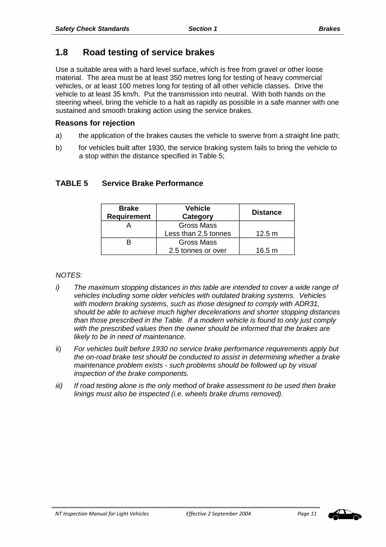
1.8 Road testing of service brakes
Use a suitable area with a hard level surface, which is free from gravel or other loose material. The area must be at least 350 metres long for testing of heavy commercial vehicles, or at least 100 metres long for testing of all other vehicle classes. Drive the vehicle to at least 35 km/h. Put the transmission into neutral. With both hands on the steering wheel, bring the vehicle to a halt as rapidly as possible in a safe manner with one sustained and smooth braking action using the service brakes.
Reasons for rejection
a) the application of the brakes causes the vehicle to swerve from a straight line path;
b) for vehicles built after 1930, the service braking system fails to bring the vehicle to a stop within the distance specified in Table 5;
TABLE 5 Service Brake Performance
Brake Requirement
Vehicle Category
Distance
A Gross Mass Less than 2.5 tonnes
12.5 m
B Gross Mass 2.5 tonnes or over
16.5 m
NOTES:
i) The maximum stopping distances in this table are intended to cover a wide range of vehicles including some older vehicles with outdated braking systems. Vehicles with modern braking systems, such as those designed to comply with ADR31, should be able to achieve much higher decelerations and shorter stopping distances than those prescribed in the Table. If a modern vehicle is found to only just comply with the prescribed values then the owner should be informed that the brakes are likely to be in need of maintenance.
ii) For vehicles built before 1930 no service brake performance requirements apply but the on-road brake test should be conducted to assist in determining whether a brake maintenance problem exists - such problems should be followed up by visual inspection of the brake components.
iii) If road testing alone is the only method of brake assessment to be used then brake linings must also be inspected (i.e. wheels brake drums removed).

This page intentionally left blank

NT Inspection Manual for Light Vehicles Effective 2 September 2004
Amended 4 December 2014
Page 13
Section 2 Towing Attachments
Safety Check Standards Section 2 Towing Attachments
NT Inspection Manual for Light Vehicles Effective 2 September 2004
Amended 4 December 2014
Page 14
Australian Design Rules relevant to this section:
ADR 42 General Safety Requirements. ADR 62 Mechanical Connections Between Vehicles.
2.1 Visually inspect the towbar and its mounting on the vehicle
body.
Reasons for rejection
a) On any towing attachment such as a tow ball, pintle hook or demountable tongue, where any of the mounting bolts, fasteners or weld beads, are loose, cracked, broken, excessively worn or extensively corroded. This includes any corresponding mounting holes and plates.
b) The towbar is not securely mounted, severely corroded or is cracked.
c) Any mounting bolts, fasteners or weld beads have advanced corrosion or are missing.
d) Where ADR 62 applies, the towbar does not display the “name” or “trademark” of the manufacturer, the “make” and “model” shown on the identity plate of the vehicle for which the towbar is designed, and the towbars “maximum rated capacity”. (The “maximum rated capacity” must be the “ATM” in tonnes or maximum “coupling ‘D-value’ in kN for which the towbar is designed and must not exceed the vehicle manufacturer’s rated towing capacity.
e) Where any part of the coupling or towbar is removable, the bolts, studs, nuts etc, fastening those parts do not have a locking device such as a U-clip, split pin, spring washer, or nylon lock nut.
f) A bicycle rack is fitted to the towbar and bicycles are not being carried.

NT Inspection Manual for Light Vehicles Effective 2 September 2004
Page 15
Section 3 Steering and Suspension
Safety Check Standards Section 3 Steering and Suspension
NT Inspection Manual for Light Vehicles Effective 2 September 2004
Page 16
Australian Design Rules relevant to this section:
ADR 10 Steering Column. ADR 42 General Safety Requirements. ADR 43 Vehicle Configuration and Dimensions. ADR 69 Full Frontal Occupant Protection.
3.1 With the engine running, check the operation of the steering
by moving the steering wheel, or, on cycle type vehicles, the
handle.
Reasons for rejection
a) Where a steering wheel is fitted, there is more than 50mm rotational free play.
b) The steering wheel is not securely attached to the steering column.
c) The steering wheel grip or cover is loose, causing the grip or cover to rotate on the steering wheel.
d) The steering wheel diameter is smaller than vehicle manufacturer’s specifications.
e) Where steering linkages are fitted to cycle type vehicles, the rotational free play exceeds 10mm measured at the end of the handle bars.
f) Where ADR 69 applies, the steering wheel is not of the same specification as the one provided by the vehicle manufacturer.
g) Where an airbag is fitted, there is any evidence that an airbag is inoperative (check the indicator light, where fitted - this usually illuminates when the ignition is first switched "on" and extinguishes after the engine is started and the airbag system passes a self-test).
3.2 Visually inspect all steering components under the bonnet
and under the vehicle.
NOTE: Take care with spring-loaded and rubber-bush joints. These components might be designed to have a certain amount of allowable movement.
Reasons for rejection
a) Any steering component is missing, cracked or broken or is worn beyond manufacturer's limits.
b) Any steering component can be seen to have been repaired or modified by heating or welding.
NOTE: Does not apply where an original component has been fitted by the manufacturer or repairs have been conducted to manufacturer's specifications.
c) Any nut, bolt or locking device is missing or insecure.
d) The steering box or rack is not securely fixed to the vehicle.
e) There is any movement on the spline between pitman arm and the steering box or between any thread or tapered joint.
f) Free play due to wear in any steering component exceeds manufacturer’s specification (if that specification is not known, free play exceeds 3mm).
g) Any power steering component is leaking, damaged or inoperative.

Safety Check Standards Section 3 Steering and Suspension
NT Inspection Manual for Light Vehicles Effective 2 September 2004
Page 17
h) Any power steering belts are loose, broken, frayed, missing, or cracked through to reinforcing plies.
3.3 Examine the idler arm.
If fitted, attempt to move the idler arm in the direction of the pivot axis.
Reason for rejection
a) the play at the end of the idler arm exceeds 8mm.
3.4 Visually inspect the suspension.
Reasons for rejection
a) Any suspension component is broken, insecure, cracked, cut, damaged, missing, or can be seen to have been repaired or modified by heating or welding or is worn beyond manufacturers' limits.
b) Any shock absorber or strut is leaking or inoperative.
c) Any shock absorber or strut is not securely mounted.
d) Any nut, bolt or locking device is missing or not secure.
e) With the wheels raised, the vertical free play of any wheel exceeds 3mm.
NOTE: Manufacturers' tolerances take precedence over specified free play measurements when performing these checks.
f) With the wheels raised, the free play of the wheel measured at the rim exceeds 6mm in total or 3mm from any component.

Safety Check Standards Section 3 Steering and Suspension
NT Inspection Manual for Light Vehicles Effective 2 September 2004
Page 18
NOTE: Manufacturers' tolerances take precedence over specified free play measurements when performing these checks.
g) Any axle or suspension component, U-Bolt, spring hangers, centre bolt etc associated with the axle installation or performance is cracked, loose, broken, damaged, missing or worn outside of manufacturers safe working limits;
h) Any springs are cracked, broken, missing, displaced more than 10% of their width or in contact with wheels, brakes or the frame;
i) Suspension travel has been altered by more than 1 third of the original manufacturer’s specifications without the Registrar’s approval;
j) Ground clearance is less than 100mm within 1 metre of an axle and/or less than one-thirtieth of the distance between the centres of adjacent axles at the midpoint between them.
Axle locating devices
Note: Superficial crazing is acceptable on rubber bushes. This is often present on rubber suspension components even when new

NT Inspection Manual for Light Vehicles Effective 2 September 2004
Amended 4 December 2014
Page 19
Section 4 Wheels and Tyres

Safety Check Standards Section 4 Wheels and Tyres
NT Inspection Manual for Light Vehicles Effective 2 September 2004
Amended 4 December 2014
Page 20
Australian Design Rules relevant to this section:
ADR 20 Safety Rims. ADR 23 Passenger Car Tyres. ADR 24 Tyre and Rim Selection. ADR 42 General Safety Requirements.
4.1 Visually inspect the inside and outside of each road wheel.
Reasons for rejection
a) Any wheel or rim is cracked, has pieces of casting missing, or is buckled or shows signs of welding.
b) Wheel nuts and bolts do not have a thread engagement length at least equal to the thread diameter, except where specified by the vehicle manufacturer, or the fitting of the wheel nut does not match the taper of the wheel stud hole.
c) Any spoked wheel has any missing, loose, broken, bent or cracked spokes.
d) The tyre or rim fouls any component at any point over the full range of suspension travel or steering movement.
4.2 Visually inspect each road tyre.
Reasons for rejection
a) The tyre has less than 1.5mm tread depth on the surfaces which normally contact the road.
b) The tyre is not compatible with the rim, has deep cuts, bulges, exposed cords or other signs of carcass failure.
c) The tyre construction of all tyres on each axle is not the same (cross ply, radial ply or bias belted).
d) The tyre has been re-grooved (except where indicated on the sidewall that the tyres are suitable for re-grooving).
e) Any retreaded tyre fitted to the vehicle is not marked with the name or identification of the retreader and speed rating of the tyre.
f) Dual tyres contact each other.

Safety Check Standards Section 4 Wheels and Tyres
NT Inspection Manual for Light Vehicles Effective 2 September 2004
Amended 4 December 2014
Page 21
g) The tyre load and/or speed rating as marked on the tyre sidewall are less than the lesser of:
(i) for a car with special features for off-road use — 140 kilometres an hour; or
(ii) for another car — 180 kilometres an hour; or
(iii) for another motor vehicle — 120 kilometres an hour; and
(iv) the vehicle’s top speed.
(v) the load ratings specified by the vehicle manufacturer, as displayed on the tyre placard; or
(vi) the ratings specified in the National Code of Practice for Light Vehicle Construction and Modification (Vehicle Standards Bulletin VSB 14) – Section LS (Part 4). This bulletin is available on the federal transport agency internet site at http://www.infrastructure.gov.au/roads/safety/bulletin/index.aspx.
Any vehicle fitted with alternative rims and tyres which have been approved as a vehicle modification by the Technical Advisory Committee (TAC) must have the rims and tyres fitted as specified in the TAC certificate or as approved by the Department.
4.3 Measure the wheel track, where modified from standard,
taking measurement from the centre of the tyres.
Reason for rejection
a) The vehicle manufacturer's specified wheel track measurement for the vehicle is exceeded by more than is currently approved as per the National Code of Practice for Light Vehicle Construction and Modification (Vehicle Standards Bulletin VSB 14) or as specified by the TAC.

This page intentionally left blank

NT Inspection Manual for Light Vehicles Effective 2 September 2004 Amended 20 August 2009
Page 23
Section 5 Body Condition
Safety Check Standards Section 5 Body Condition
NT Inspection Manual for Light Vehicles Effective 2 September 2004 Amended 20 August 2009
Page 24
ADRs applicable to this section:
ADR 2 Sliding Door Latches and Hinges. ADR 8 Safety Glazing Material ADR 10 Steering Column. ADR 11 Internal Sunvisor. ADR 15 Demisting of Windscreen. ADR 21 Instrument Panel. ADR 25 Anti-Theft Lock. ADR 29 Side Door Strength. ADR 34 Child Restraint Anchorages and Child Restraint Anchor Fittings. ADR 42 General Safety Requirements. ADR 43 Vehicle Configuration and Dimensions
5.1 Check the operation of all doors, door locks and latches and
the bonnet lock and latches.
Reason for rejection
a) Any inside or outside door latch, control or hinge is not secure or functional.
b) Any bonnet or similar panel which covers the engine, luggage space or battery compartment and which is forward of the windscreen, does not have a device to secure the panel in the closed position.
c) Any bonnet or similar panel which opens from the front (that is, the hinges are at the back) and which, when opened, would obstruct the driver's view through the windscreen, does not have a primary and secondary securing device.
d) Any hinges, or slides for doors, tailgates, sidegates, hatches or compartment covers are damaged or worn and likely not to prevent load or passenger from falling off.
5.2 Visually inspect the windscreen and windows.
Reason for rejection
a) The wiped area of the windscreen in front of and on the same side of the vehicle as the driver, has:
damage (such as scoring, sandblasting or severe discolouration) that interferes with the driver’s view;
any bulls-eye or star fracture that exceeds 16 mm in diameter, or any two (2) of the following;
hairline crack up to 30 mm long;
a crack from the edge of the windscreen up to 75 mm long.
NOTE: Grooves in windscreens that are designed specifically to clean the wiper blades are not regarded as damage unless they affect the driver’s view. Approved grooving is usually identified by the installer.
b) Any cracks in a laminated windscreen penetrate more than one layer of glass or are more than 150mm long.
c) Any glazing used in any motor vehicle is not safety glass (except a caravan) and where ADR 8 applies, the glass does not display an identification mark or symbol.
d) Glazing is loose in its frame or cracked to the extent that sharp edges are exposed.

Safety Check Standards Section 5 Body Condition
NT Inspection Manual for Light Vehicles Effective 2 September 2004 Amended 20 August 2009
Page 25
e) Glazing, other than the windscreen, that is necessary for the driver to see the road is discoloured, obscured, badly scratched, sandblasted or fractured to the extent that it interferes with the driver’s view.
f) Items that obscure the driver’s view or the corresponding area on the other side of the windscreen.
EXCEPTION: Any two of the following three types of damage are acceptable:
NOTE: This rule applies to windscreens repaired with clear resins. After repair, there must be no visible damage beyond the limits given above.
5.3 Test the light transmittance level of the windscreen, side and
rear windows.
NOTE:
(i) This section should be read in conjunction with the light meter manufacturers' instructions.
(ii) The light meter may have up to a 5% measuring inaccuracy. A vehicle may be accepted if the readings are up to 5% lower than the minimum light transmittance.
(iii) The light transmission requirements do not apply to a tinted or opaque band at the top of the windscreen, provided they are above the arc swept by the windscreen wipers, or 10% of the depth of the windscreen whichever is the greater.

Safety Check Standards Section 5 Body Condition
NT Inspection Manual for Light Vehicles Effective 2 September 2004 Amended 20 August 2009
Page 26
Reasons for rejection
a) The visible light transmittance of any glazing (including any applied film) is less than that detailed below:
Glazing Minimum Light Transmittance
Vehicles NOT TO BE REJECTED until meter readings are LESS than
Windscreen 75% 70%
Driver and front passenger side windows
35% 30%
Internal window partitioning
70% 65%
All other windows 15% 10%
No limit for windows to the rear of the driver for the following categories: LEG1, LEG2, MD.
Any in-service goods carrying vehicle that has glass panels (glazing) fitted in lieu of solid panels, or a bus which has glazing fitted in positions that are not required for vision when controlling the vehicle, may tint these glass panels to any LT percentage to meet operational needs.
Any vehicle fitted with window tint with a LT of less than 70% must have external rear vision mirrors fitted to both sides of the vehicle.
b) Any coating or tint applied to vehicle windows and windscreens is reflective (i.e. reflectance must not exceed 10 %).
c) Any coating or tint applied to vehicle windows and windscreens is non-uniform (i.e. is bubbling or gives distorted image).
5.4 Visually inspect body panels, chassis and subframe for
dangerous protrusions and rust.
Reasons for rejection
a) Exterior body work and fittings have sharp edges due to rusted panels or body damage, or protrusions of any aftermarket object or fittings, not technically essential to the operation of the vehicle, which protrudes from any part of the vehicle that could cause injury to a person coming into contact with the vehicle.
b) Any structural member such as a subframe, floor panel, door sill, seat or seat belt anchorage, is cracked or has advanced rust.
c) Where ADR 29 applies, the doors of a vehicle have advanced rust.
d) Chassis frame members or supporting members are cracked, loose, sagging or broken.
e) Frame members in load areas are missing, damaged or unsecured.
f) Tilting cabin or tray latches do not hold the cabin or tray securely in the operating position.
g) Any body, chassis or subframe repairs on the vehicle have not been carried out in accordance with recognised industry repair methods and standards.

Safety Check Standards Section 5 Body Condition
NT Inspection Manual for Light Vehicles Effective 2 September 2004 Amended 20 August 2009
Page 27
5.5 Inspect the wheel arches/mudguards and mudflaps, with the
wheels in the "straight ahead" position.
Reasons for rejection
a) Mudguards are not fitted to all wheels of passenger and goods type vehicles;
b) The mudguard and/or bodywork covering any wheel is not at least as wide as the tyre over the arc between points A and B in the diagram;
c) Point C (being on the rear edge of the mudguard/mudflap/ bodywork and in line with the centreline of the tyre - see diagram) is more than 150mm in vertical distance above the centre of the wheel. NOTE: Points along the rear edge which are inboard of Point C should also meet this requirement. A mudflap which is too flexible to maintain its position during normal driving conditions should be disregarded for this check.
5.6 Visually inspect rear vision mirrors
Reasons for rejection
a) Rear vision mirrors are cracked, loss of reflectivity, missing, or do not provide a clear view of the road to the rear of the vehicle.
b) Where there is no effective rear vision provided by the internal rear vision mirror, the vehicle does not have an external rear vision mirror fitted to each side.
c) Any light commercial vehicle (except a station wagon) is not fitted with an external rear vision mirror on each side of the vehicle.
d) Mirrors are not securely mounted.
e) Any vehicle with window tint with a Luminous Transmittance (LT) of less than 70% does not have an external rear vision mirror on both sides of the vehicle.
5.7 Visually inspect and check the operation of the windscreen
wipers and windscreen washers.
Reasons for rejection
a) Windscreen wipers are missing, are not secured, or do not operate on any speed position.

Safety Check Standards Section 5 Body Condition
NT Inspection Manual for Light Vehicles Effective 2 September 2004 Amended 20 August 2009
Page 28
b) Windscreen wiper blades are missing, cracked, curled, frayed, torn, or ineffective.
c) Windscreen washers do not work or are not correctly aimed onto the windscreen.
5.8 Check the operation of the horn.
Reasons for rejection
a) The horn is not working.
b) The horn is of the following types: exhaust whistle, compression whistle, siren or alternating tone (reversing alarms are acceptable).
5.9 Visually inspect the front and rear number plates.
Reasons for rejection
a) Number plate is obscured, for example by a towing attachment goose neck, tow ball, protective cover and or frame.
b) The number plate is damaged or faded to the extent that the registration number is not legible.
c) The registration (number) plate is not issued or approved by the registrar of motor vehicles.
5.10 Where ADR 25 applies, check the operation of the anti-
theft/steering lock.
Reasons for rejection
a) The ignition key can be removed in any position except the "anti-theft" (lock) position.
b) When engaged, the anti-theft lock does not prevent at least one of the following actions:
i) steering the vehicle;
ii) engaging the forward drive gears;
iii) release of the brakes.
5.11 Where ADR15 applies, check the operation of the windscreen
demister.
Reasons for rejection
a) The demister unit is missing.
b) There is no air being blown onto the windscreen when the demister is turned on.

Safety Check Standards Section 5 Body Condition
NT Inspection Manual for Light Vehicles Effective 2 September 2004 Amended 20 August 2009
Page 29
5.12 Speedometer
Reason for rejection
a) speedometer is not operational;
b) speedometer indicator values are not legible.

This page intentionally left blank
NT Inspection Manual for Light Vehicles Effective 2 September 2004
Page 31
Section 6 Seats and Seatbelts

Safety Check Standards Section 6 Seats and Seatbelts
NT Inspection Manual for Light Vehicles Effective 2 September 2004
Page 32
Australian Design Rules relevant to this section:
ADR 3 Seat Anchorages ADR 4 Seatbelts. ADR 5 Anchorages for Seatbelts and Child Restraints. ADR 22 Head Restraints. ADR 34 Child Restraint Anchorages and Child Restraint Anchor Fittings. ADR 69 Full Frontal Impact Occupant Protection.
6.1 Check seats
Reasons for rejection
a) Seat frames or attaching points are loose, cracked, broken or have fasteners missing.
b) Adjustment mechanisms do not work properly or any securing device does not hold the seat in the selected position.
c) Any seat has an exposed sharp edge or other parts that protrude due to damage.
6.2 Check seat belts
Reasons for rejection
a) Any seat belt or attaching point (including child restraint point) is loose, cracked or has missing fasteners.
b) Any retractor, buckle or adjustment device is inoperative.
c) Webbing is cut, burnt, tied in a knot, frayed, stretched, severely deteriorated or has broken stitching.
NOTE: Discolouration alone is not reason for rejection.
6.3 Check child restraints
Inspect the child restraint anchorage points and the installation and condition of any child restraints devices fitted in the vehicle.
Reasons for rejection
a) In other than ADR 34 vehicles, where fitted, child restraint attachment anchorage points are loose, cracked or corroded to the point of weakening the anchorage.
b) In other than ADR 34 vehicles, any child restraint device installed in a vehicle that is not attached to an anchorage point installed as an approved vehicle modification.
c) Where ADR 34 applies, child restraint attachment anchorage points are loose, cracked, corroded to the point of weakening the anchorage or missing.
d) Where ADR 34 applies, any child restraint device installed in a vehicle that is not attached to the vehicle manufactures anchorage point.
e) Incorrect anchorage bolts, nuts and spacers fitted.
f) Any anchorage points that have been weakened or obstructed by the fitting of accessories (e.g. Radio speakers).
g) Child restraint belt webbing is not correctly secured to each end fitting or is damaged, frayed, split, torn, altered or modified.

Safety Check Standards Section 6 Seats and Seatbelts
NT Inspection Manual for Light Vehicles Effective 2 September 2004
Page 33
h) Child restraint device is structurally defective (e.g. Casing cracked or damaged in structural areas, assembly bolts or rivets missing, loose or deteriorated.
i) Any restraint that is not correctly installed in an adult seating position complying with the restraint manufactures instructions.
j) Seatbelt and tether strap securing a restraint are twisted, knotted, frayed, torn or damaged in any way.

This page intentionally left blank
NT Inspection Manual for Light Vehicles Effective 2 September 2004
Amended 4 December 2014
Page 35
Section 7 Lighting

Safety Check Standards Section 7 Lighting
NT Inspection Manual for Light Vehicles Effective 2 September 2004
Amended xx December 2014
Page 36
Australian Design Rules relevant to this section:
ADR 1 Reversing Lamps. ADR 6 Direction Indicator Lamps. ADR 13 Installation of Lighting and Lighting Signalling Devices other than L-Group. ADR 45 Lighting and Light Signalling Devices not Covered by ECE Regulations. ADR 46 Head Lamps. ADR 47 Reflex Reflectors. ADR 48 Rear Registration Plate Illuminating Devices. ADR 49 Front and Rear Position (side) Lamps, Stop Lamps and End-Outline Marker
Lamps. ADR 51 Filament Globes. ADR 60 Centre High Mounted Stop Lamps. ADR 58 Requirements for Omnibuses Designed for Hire and Reward. ADR 76 Daytime Running Lamps.
7.1 Visually inspect the compulsory reflectors fitted to the rear
of the vehicle.
Reason for rejection
a) Red reflector(s) are damaged, discoloured or missing (note: reflectors may be incorporated in the lamp assembly).
7.2 Visually inspect and check the operation of all lights fitted to
the vehicle.
Reasons for rejection
a) Any of the following lights do not work or has incorrect colour:
i) headlight (high/low beam) (white);
ii) front park or side lights (white);
iii) tail lights (red);
iv) brake light(s) (red);
v) turn signal indicator lights (yellow);
vi) clearance lights (trucks and cycle type vehicles only) (front: yellow/white, side: yellow, rear: yellow/red);
vii) number plate light (white).
b) Any rear light other than a reversing light is in a condition or damaged to the extent that white light shows to the rear of the vehicle.
c) Any yellow clearance light or front turn signal is damaged so that it shows white light.
d) The number plate light is not directing light onto the surface of the rear number plate.
e) Lights as follows are not fitted to pre 3rd Edition vehicles (passenger and light goods vehicles and light omnibuses) (dimensions at centre of lights).

Safety Check Standards Section 7 Lighting
NT Inspection Manual for Light Vehicles Effective 2 September 2004
Amended xx December 2014
Page 37
At front of vehicle: (Pre 3rd Edition vehicles only)
1 White Main beam headlights, min 500mm and max 1400mm off ground, with min separation of 600mm;
2 White Dipped beam headlights, min 500mm and max 1400mm off ground, min 600mm separation;
2 White Parklights, min 500mm off ground, max 500mm inboard of vehicle side, wired to remain “on” with headlights if vehicle built after 7/71;
2 Yellow turn signal indicators (7/73 onwards, pre 7/73 may be white), min 350mm and max 2000mm off ground, min 750mm separation, max 500mm inboard of vehicle side;
2 Yellow or White clearance lights (where vehicle is over 2.2m wide), min 750mm above headlights, max 150mm inboard of side of vehicle;
2 Hazard warning lights (9/83 onwards), incorporated with turn signal indicators;
Additional head lights as per main or dipped beam headlights.
Fog Lights:
Optional White or yellow fog lights, mounted no higher than the headlights wired through park lights on a separate switch, may also operate when main and/or dipped beam headlights are illuminated;
At Side of vehicle:
2 Yellow to front, red to rear side marker lamps (where vehicle is more than 2.2m wide and/or 7.5m long), min 600mm and max 1500mm off ground, max 300 mm from rear of vehicle;
At Rear of vehicle:
2 (1 prior to 7/88) Red tail lights, max 1500mm off ground, min 600mm apart, max 400mm inboard of side of vehicle (single light located in centre or right side of vehicle);
2 Red reflectors, max 1500mm off ground, max 400mm (250mm if vehicle more than 2.2m wide) inboard of side of vehicle;
2 (8/72 onwards) white or yellow reverse lights, max 1200mm off ground;
White registration plate lamp/s, to illuminate registration plate;
2 (1 prior to 7/88) Red stop lights, min 300mm and max 1500mm off ground (single light to be in centre or on right side of vehicle);
2 Yellow (red permitted prior to 1/73) turn signal indicators, min 350mm and max 1500mm off ground, min 600mm separation.
f) Any optional lights or reflectors interfere with any compulsory lights or reflectors.
Safety Check Standards Section 7 Lighting
NT Inspection Manual for Light Vehicles Effective 2 September 2004
Amended xx December 2014
Page 38
7.3 Visually inspect front and rear lights for the presence of
tinted covers.
Reasons for rejection
a) Any light has a tinted cover over it, or any tinting applied to it.
b) There is any opaque cover over a headlight which cannot be readily removed without the use of tools.
7.4 Using a headlight tester or testing screen, check the aim of
the headlights.
Reasons for rejection
a) The aim of the headlight is adjusted such that, when on high beam and measured at an effective distance of 8m, the projected centre of the beam is to the right of the headlight centre and/or is above the headlight centre.
b) When measured at an effective distance of 8m, any part of the top edge of the high intensity portion of the low beam pattern is above and to the right of the centreline of the headlight.
NOTES:
i. in the region above and to the right of the centreline of the headlight the luminous intensity must not exceed 437cd.
ii. the portion of the beam to the left of the centreline of the light may extend above the height of the centreline of the headlight.
iii. the "centreline of the headlight" passes through the centre of the globe filament, or equivalent.
c) The headlight high beam indicator light is not operating.
7.5 Visually inspect the headlights.
Reasons for rejection
a) Headlight reflector is tarnished or peeling to the extent that headlight performance is impaired.
b) Headlight lens is cracked or broken.
c) Headlight assembly is not secured or is out of position.
d) Headlight does not show white light.
e) More than 4 main beam headlights are fitted.
f) More than 8 combined main beam headlights and driving lights are fitted.

NT Inspection Manual for Light Vehicles Effective 2 September 2004
Page 39
Section 8 Engine Compartment &
Driveline

Safety Check Standards Section 8 Engine and Driveline
NT Inspection Manual for Light Vehicles Effective 2 September 2004
Page 40
ADRs applicable to this section:
ADR 17 Fuel System. ADR 28 External Noise of Motor Vehicles. ADR 37 Emission Control for Light Vehicles. ADR 39 Exhaust Noise of Motor Cycles. ADR 41 Mandatory Operation on Unleaded Petrol. ADR 42 General Safety Requirements. ADR 70 Exhaust Emission Control for Diesel Engine Vehicles.
8.1 Visually inspect the engine, transmission and driveline,
operate the transmission control.
Reasons for rejection
a) There are oil leaks from the engine, gearbox or driveline which allow oil to drop onto the road surface, exhaust system or brake components.
b) Any engine or transmission mounting is broken or not secured.
c) Fasteners on couplings in the driveline are loose or missing.
d) Any transmission drive shaft is bent, damaged, loose or noticeably misaligned.
e) Any universal or constant velocity joint has excessive wear, is misaligned, seized, is not securely attached, or has a damaged or missing boot.
f) Where the engine is non-standard, the engine number does not match the number
shown on the registration certificate *;
* —contact the MVR.
g) Where an automatic transmission is fitted, the engine can be started in any gear position other than neutral or park (ensure that brakes are applied during this test), or gear selector indicator is not operational or is not illuminated (when headlights are turned on).
h) Where the motor cycle chain or belt guard is cracked ,broken or missing.
i) Batteries are not securely mounted or leak.
j) Electrical wiring or connectors are damaged or hanging loose.
8.2 Visually inspect the exhaust system.
Reasons for rejection
a) Any component of the exhaust system is not securely mounted or is fouling on any other component.
b) Exhaust pipe outlet is not rearward of all side passenger doors and opening windows or discharges to the left hand side of the vehicle.
c) Exhaust pipe outlet does not extend at least 40mm beyond the furthermost outboard or rearmost joint of the floor pan which is not continuously welded or permanently sealed which could permit direct access of exhaust gases to the passenger compartment, but not beyond the perimeter of the vehicle when viewed in plan.
d) There is any leak in the exhaust system, excluding manufacturers' drain holes in the mufflers.

Safety Check Standards Section 8 Engine and Driveline
NT Inspection Manual for Light Vehicles Effective 2 September 2004
Page 41
e) Exhaust outlet does not extend to the outline of the vehicle body.
f) Emission control equipment (where required) missing or not operative.
g) The engine lets out sparks, flames, excessive gases, oil or fuel residue.
h) For a vehicle manufactured after 1930 and propelled by an internal combustion engine, the vehicle emits visible emissions for a continuous period of more than 10 seconds.
NOTE: a vehicle should not be rejected for emissions that are visible only because of heat or the condensation of water vapour.
8.3 Where ADR 37 applies, check for the presence of a catalytic
converter.
Reason for rejection
a) There is no catalytic converter fitted, where one was originally provided or has a missing heat shield.
b) The catalytic converter has been bypassed.
8.4 Visually inspect the fuel system.
Reason for rejection
a) There is any leakage from the fuel system.
b) Any part of the fuel system is insecure or damaged so that there is a risk of a fuel leak.
c) The fuel cap is missing, insecure, or of the incorrect type.

Safety Check Standards Section 8 Engine and Driveline
NT Inspection Manual for Light Vehicles Effective 2 September 2004
Page 42
8.5 Stationary Exhaust Noise
Where it is evident that a vehicle is emitting significantly higher noise than normal, the vehicle must not be passed as fit for registration. The customer must be referred to the nearest MVR Vehicle Standards Centre where a stationary noise test will be conducted in accordance with Appendix B - National stationary exhaust noise test procedures for in-service motor vehicles, by an MVR Transport Inspector.
Reason for rejection
a) The measured noise level exceeds the limit shown in the table.
Table of Noise Limits for Cars and Car Derivatives
Noise tests conducted from 1 January 2001
Vehicle manufactured from 1 January 1983 90dB(A)
Vehicle manufactured before 1 January 1983 96dB(A)
NOTE: Different limits apply to motorcycles, trucks and buses.

NT Inspection Manual for Light Vehicles Effective 2 September 2004 Page 43
Section 9 Fuel Systems
LPG/NGV/CNG
Safety Check Standards Section 9 Fuel Systems LPG/NGV/CNG
NT Inspection Manual for Light Vehicles Effective 2 September 2004 Page 44
Australian Design Rules relevant to this section:
ADR 17 Fuel Systems. ADR 44 Specific Purpose Vehicle Requirements
9.1 Visually inspect for the installation of a Liquid Petroleum Gas
(LPG), Natural Gas Vehicle (NGV) or Compressed Natural
Gas (CNG) system.
Vehicles equipped with LPG/NGV/CNG installations require a safety system check conducted by an authorised gas fitter/installer in accordance with the requirements of AS 1425 for LPG and AS 2739 for CNG/NGV.
These periodical checks must be conducted at every roadworthy inspection (for the purpose of registration renewal).
Reasons for rejection
a) The vehicle has not had a safety system check conducted by an authorised gas fitter/installer within a 6 week period of the roadworthy inspection.
b) The vehicle fails the safety system check.
Vehicles with systems installed within the Northern Territory
Installation of LPG/NGV/CNG must be carried out in accordance with NT regulations and licensing requirements.
9.2 Visually inspect for the presence of an approved
LPG/NGV/CNG modification plate and number plate labels.
A vehicle which has an LPG/NGV/CNG fuel system fitted must have a metal plate fitted in a prominent position in the engine bay, showing;
a statement that the installation complies with the Standards Australia code for the fuel type (AS1425 for LPG and AS2739 for CNG/NGV);
the date the installation was commissioned;
the State or Territory where installation was made, and
the identification number of the suitably qualified installer.

Safety Check Standards Section 9 Fuel Systems LPG/NGV/CNG
NT Inspection Manual for Light Vehicles Effective 2 September 2004 Page 45
Reasons for rejection
a) The vehicle does not have an approved LPG/NGV/CNG modification plate. Acceptable plates are either;
i) a plate fitted by a State or Territory authorised/licensed gas fitter/installer; or
ii) a plate fitted by the vehicle manufacturer, where the LPG/ NGV or CNG system was installed by the original vehicle manufacturer.
The following are examples of acceptable plates that have been fitted by vehicle manufacturers.
b) Number plate labels are not fitted to the front and rear of the vehicle indicating it is LPG/NGV/CNG fuelled. Acceptable number plate labels are shown below.
NISSAN MOTOR CO. AUSTRALIA PTY LTD.
CERTIFICATION PLATE
THE LPG INSTALLATION IN THIS VEHICLE
COMPLIES WITH THE FOLLOWING APPROVALS
VIC
NSW
QLD
WA
V447-80
NO255Q
SA
NT
ACT
TAS
THELPG SYSTEM COMPLIESWITH ADR44/01 & AS1425-1989
INSTALLED BYLICENCED WORKSHOPNo.AFR00050
V.I.N.
ENGINENo. DATE / /
L.P.G.SERIALNo.
LPG INSTALLATION HOLDEN COMMODORE
MODELVSSTYLESEDAN
THISINSTALLATION COMPLIESWITH ADR44/01, AS1425-1989 AND
GM HOLDENSAUTOMOTIVEINSTALLATION REQUIREMENTS
ODOMETER
V.I.N.
STATE/TERRITORYDATEOF INSTALLATION ___/___/___
ENGINENo.
WORKSHOP
FITTER (CERTIFICATENo.)
(LICENCENo.)
iNSTALLATION REFERENCENo.

This page intentionally left blank
NT Inspection Manual for Light Vehicles Effective 2 September 2004
Page 47
Section 10 Fuel Systems
Petrol/Diesel
Safety Check Standards Section 10 Fuel Systems Petrol/Diesel
NT Inspection Manual for Light Vehicles Effective 2 September 2004
Page 48
Australian Design Rules relevant to this section:
ADR 17 Fuel System.
10.1 Visually inspect the fuel system.
Reasons for rejection
a) There is any leakage from the fuel system.
b) Fuel lines are in contact with moving parts or a heat source, are kinked, cracked or not secure.
c) Fuel tanks are not securely mounted and straps, supports, mounting brackets or fasteners are missing, cracked, broken or loose.
d) Fuel tanks are damaged or corroded so that leaks could result.
e) Fuel filler cap is missing or not suitable for the type of tank.
f) Fuel filler cap seal is damaged or missing.
g) The fuel filler restrictor is missing from the filler neck of a vehicle exclusively designed for unleaded fuel and fitted with a catalytic convertor

NT Inspection Manual for Light Vehicles Effective 2 September 2004
Amended 4 December 2014
Page 49
Section 11 Motorcycles

Safety Check Standards Section 11 Motorcycles/Brakes
NT Inspection Manual for Light Vehicles Effective 2 September 2004
Amended 4 December 2014
Page 50
Australian Design Rules relevant to this section:
ADR 7 Hydraulic Brake Hoses ADR 33 Brake Systems for Motorcycles and Mopeds.
11.1 Visually inspect the condition of the brake controls.
Reasons for rejection
a) On rubber faced brake pedals, any metal is showing.
b) On metal brake pedals, there is no anti-slip surface.
c) Missing or broken pedal or handle.
11.2 Check the operation of the brake controls
Sit in the rider's position and put the transmission into neutral or operate the clutch. Apply each brake while attempting to move the cycle forward.
Reasons for rejection
a) When the brakes are firmly applied, less than 20% of the pedal or handle travel remains.
b) Any wheel brake is not functioning.
c) When steady moderate pressure is applied for 10 seconds, the pedal or handle does not hold its position or, where ADR33 applies, the brake failure indicator comes on.
11.3 Inspect the condition of visible brake components.
Reason for rejection
a) Where visible, any brake component is leaking or is not securely mounted.
b) Any brake cable is frayed, seized or otherwise damaged.
c) Where visible, any brake lining is worn to the extent that only 1.0 mm of lining thickness remains at any point.
d) Where hydraulic brakes are fitted, the level of brake fluid is below the minimum indicated level.
e) Where ADR 7 applies, any brake hose is not marked with manufacturer’s name, and any braided hose is missing protection sleeves.
11.4 Check the operation of the parking brake on ADR 33 cycles
fitted with side-car outfits.
Put the transmission in neutral, apply parking brake and attempt to move the outfit.
Reasons for rejection
a) There is no parking brake fitted.
b) The parking brake fails to stop the outfit being moved.

Safety Check Standards Section 11 Motorcycles/Towing Attachments
NT Inspection Manual for Light Vehicles Effective 2 September 2004
Amended 4 December 2014
Page 51
Australian Design Rules relevant to this section
ADR 62 Mechanical Connections Between Vehicles.
11.5 Visually inspect the towbar and its mounting to the frame.
Reasons for rejection
a) Any towing attachment such as a tow ball is loose or is cracked.
b) The towbar is not mounted directly to the frame or through rigid connections to the frame.
c) The towbar is not securely mounted, or is cracked.
d) Any mounting bolts, fasteners or weld beads have advanced corrosion or are missing.
e) Where ADR 62 applies, the towbar does not display the gross mass rating and manufacturer's name or trademark (a label may be affixed to the vehicle for this purpose).
f) Where any part of the coupling or towbar is intended to be removable, the bolts, studs, nuts etc. Fastening those parts do not have a locking device such as u-clip, split pin, spring washer, nylon lock nut.

Safety Check Standards Section 11 Motorcycles/Steering/Suspension
NT Inspection Manual for Light Vehicles Effective 2 September 2004
Amended 4 December 2014
Page 52
11.6 Visually inspect all steering components.
NOTE: On most motor cycles this will normally only apply to the steering damper, however, there are some specialised cycles fitted with remote steering controls or centre-hub steering to which this check is more appropriate.
Reasons for rejection
a) Where steering linkages are fitted, the rotational free play exceeds 10mm measured at the end of the handlebars.
b) Any steering component can be seen to have been repaired or modified by heating or welding.
NOTE: Does not apply where an original component has been fitted by the manufacturer or repairs have been conducted to manufacturer's specifications.
c) Any nut, bolt, or locking device is missing or insecure.
d) Any steering component is insecure, broken, missing or has noticeable free play beyond manufacturer's limits.
e) The steering assembly fails to turn from "lock to lock" position without jamming, fouling or roughness in its operation.
f) Where a motorcycle has been fitted with replacement handle bars and does not meet the following requirements:
Motorcycles manufactured before 1 July 1988
The handlebar must have the same shape and be of the same length on either side of the front wheel and steering head assembly.
The distance between the extreme ends of the handlebar (V) must not be less than 550 mm.
The highest point on the handlebar must not be more than 380 mm (W) above the top of the steering yoke.
Where the highest point of the handlebar is more than 205 mm vertically above the top of the steering yoke (W), the distance between the extreme ends of the handle bar (V) must not be less than 660mm
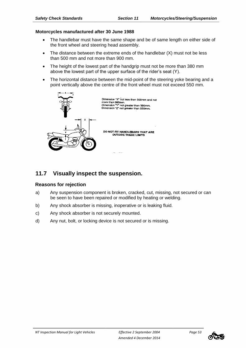
Safety Check Standards Section 11 Motorcycles/Steering/Suspension
NT Inspection Manual for Light Vehicles Effective 2 September 2004
Amended 4 December 2014
Page 53
Motorcycles manufactured after 30 June 1988
The handlebar must have the same shape and be of same length on either side of the front wheel and steering head assembly.
The distance between the extreme ends of the handlebar (X) must not be less than 500 mm and not more than 900 mm.
The height of the lowest part of the handgrip must not be more than 380 mm above the lowest part of the upper surface of the rider’s seat (Y).
The horizontal distance between the mid-point of the steering yoke bearing and a point vertically above the centre of the front wheel must not exceed 550 mm.
11.7 Visually inspect the suspension.
Reasons for rejection
a) Any suspension component is broken, cracked, cut, missing, not secured or can be seen to have been repaired or modified by heating or welding.
b) Any shock absorber is missing, inoperative or is leaking fluid.
c) Any shock absorber is not securely mounted.
d) Any nut, bolt, or locking device is not secured or is missing.

Safety Check Standards Section 11 Motorcycles/Steering/Suspension
NT Inspection Manual for Light Vehicles Effective 2 September 2004
Amended 4 December 2014
Page 54
e) With the wheels raised, the vertical free play of any wheel exceeds 3mm;
NOTE: The free play measurement given is a guide only, and manufacturers' tolerances take precedence in all cases when performing these checks.
f) With the wheels raised, the free play of the wheel measured at the rim exceeds 6mm in total or 3mm from any component part.
NOTE: The free play measurement given is a guide only, and manufacturers' tolerances take precedence in all cases when performing these checks.

Safety Check Standards Section 11 Motorcycles/Wheels/Tyres
NT Inspection Manual for Light Vehicles Effective 2 September 2004
Amended 4 December 2014
Page 55
11.8 Inspect both sides of each road wheel.
Reasons for rejection
a) Any wheel or rim is cracked, has pieces of a casting missing, or is buckled.
b) Any hub has missing or broken wheel mounting nuts, studs or bolts.
c) Any spoked wheel has missing, loose, broken, bent or cracked spokes.
d) The tyre or rim fouls any component at any point over its full range of travel.
11.9 Visually inspect each road tyre.
Reasons for rejection
a) The tyre has less than 1.5mm tread depth on the surfaces which normally contact the road.
b) The tyre has deep cuts, bulges, exposed cords or other signs of carcass failure.
c) The tyre has identifiers indicating "NOT FOR HIGHWAY USE".

Safety Check Standards Section 11 Motorcycles/Body
NT Inspection Manual for Light Vehicles Effective 2 September 2004
Amended 4 December 2014
Page 56
11.10 Visually inspect body panels, chassis and frame for
dangerous protrusions and rust.
Reasons for rejection
a) Exterior body work, fairings and fittings have sharp edges due to rusted or fractured panels, or other damage that could cause injury to a person coming into contact with them.
b) Any structural member such as the chassis or frame, is cracked or has advanced rust.
c) Any body, chassis or subframe repairs on the vehicle have not been carried out in accordance with recognised industry repair methods and standards.
11.11 Inspect the mudguards.
Reasons for rejection
a) Mudguards are not fitted to all wheels.
b) The motorcycle or side car mudguard does not fully cover the width of the tyre.
c) The wheel guard is not designed to protect other road users as far as practicable, against thrown-up stones, mud, ice, snow and water and does not reduce, for those users, dangers due to contact with the moving wheels.
ADR 42/04 requirements relating to mudguard extension requirement were repealed on 12 September 2014.
Mandatory mudguard requirements still apply.
11.12 Visually inspect rear vision mirror(s).
Reason for rejection
a) Rear vision mirror(s) is (are) missing, or do not provide a clear view of the road to the rear of the cycle.
b) Two rear vision mirrors are not fitted to motorcycles manufactured after June 1975.

Safety Check Standards Section 11 Motorcycles/Body
NT Inspection Manual for Light Vehicles Effective 2 September 2004
Amended 4 December 2014
Page 57
11.13 Check the operation of the horn.
Reasons for rejection
a) The horn is not working.
b) The horn is of the following types: exhaust whistle, compression whistle, siren or alternating tone (reversing alarms are acceptable).
11.14 Visually inspect any exposed drive chain, belt, shaft and
sprockets
Reason for rejection
a) The drive chain, belt or shaft is not protected by the frame or by a guard extending at least 300mm rearward of the rear most footrest, or to the vertical centre of the drive sprocket.
Safety Check Standards Section 11 Motorcycles//Lighting
NT Inspection Manual for Light Vehicles Effective 2 September 2004
Amended 4 December 2014
Page 58
11.15 Visually inspect the number plate(s).
Reasons for rejection
a) Number plate is obscured, for example by a towing attachment protective cover and/or frame.
b) The number plate is obscured, damaged or faded to the extent that the registration number is not legible.
c) The number plate is not issued or approved by the registrar of motor vehicles.
11.16 Indicators
A motorcycle that is fitted with indicators complying with the ADRs applicable to motorcycle indicators is not required to comply with this part.
Motorcycles manufactured prior to June 1975
Indicators not required to be fitted. If fitted, indicators are to comply with minimum requirements.
Minimum Indicator Requirements
Minimum requirements are outlined in Division 11 Direction indicator lights of the AVSRs.
Length Positioning - maximum 300mm from rear measured from rearmost point of motorcycle to edge of illuminating surface.

Safety Check Standards Section 11 Motorcycles//Lighting
NT Inspection Manual for Light Vehicles Effective 2 September 2004
Amended 4 December 2014
Page 59
Motorcycle Indicators
Visibility Angles
Motorcycle Indicators
Positioning
Rear Indicators
SpacingFront Indicators
Spacing
Alternative Minimum Requirements
If indicators are fitted, the following items will take precedence over the corresponding requirements outlined in the AVSRs. All other requirements of the AVSRs will apply.
Visibility from 30 metres (150 above and below the horizontal plane, from the vertical plane 200 toward centreline of motorcycle and 800 away).
Distance Apart – front indicators minimum 240mm, rear indicators minimum 180mm measured between edges of illuminating surfaces.
Height Positioning – minimum 350mm, maximum 1200mm measured from ground to edge of illuminating surface.
Safety Check Standards Section 11 Motorcycles//Lighting
NT Inspection Manual for Light Vehicles Effective 2 September 2004
Amended 4 December 2014
Page 60
11.16 Visually inspect the compulsory reflectors fitted to the rear
of the cycle.
Reason for rejection
a) Red reflector(s) are damaged, discoloured or missing (note: reflectors may be incorporated in the lamp assembly).
11.17 Visually inspect and check the operation of all lights fitted
to the cycle.
Reasons for rejection
a) Any of the following lights do not work or has incorrect colour:
i) headlight (high/low beam) (white);
ii) tail light (red);
iii) brake light(s) (red);
iv) turn signal indicator lights (yellow);
v) side-car marker light (white/red);
vi) number plate light (white).
b) Any of the above lights are damaged to the extent that white light shows to the rear of the cycle.
c) Any amber turn signal light is damaged so that it shows white light.
d) The number plate light is not directing light on to the surface of the rear number plate.
e) Lights as follows are not fitted to pre 3rd edition vehicles (mopeds, motor cycles, motor cycle and sidecar, and motor tricycle) (dimensions at centre of lights):
At front of vehicle:
1 White Main beam headlight, min 500mm and max 1400mm off ground;
1 White Dipped beam headlights, min 500mm and max 1400mm off ground;
1 White Parklights, min 500mm off ground;
2 Yellow turn signal indicators (June 1975 onwards), min 425mm and max 2000mm off ground, min 300mm separation;
Optional White or yellow fog lights, wired through park lights on a separate switch, not higher than headlights;
Optional driving lights as per main or dipped beam headlights.

Safety Check Standards Section 11 Motorcycles//Lighting
NT Inspection Manual for Light Vehicles Effective 2 September 2004
Amended 4 December 2014
Page 61
At Rear of vehicle;
1 Red tail light, max 1000mm (1500mm if 1000mm impractical) off ground;
1 (2 for motorcycle and side car and motor tricycles) Red reflectors, max 1000mm (1500mm if 1000mm impractical) off ground, max 400mm (for motorcycle and side car and motor tricycle) inboard of side of vehicle;
1 (2 for motorcycle and side car and motor tricycle) Red stop lights, min 350mm off ground, max 400mm (for motorcycle and side car and motor tricycle) inboard from side of vehicle;
White registration plate lamp/s, to illuminate registration plate;
2 Yellow turn signal indicators (June 1975 onwards), min 425mm and max 2000mm off ground, min 300mm separation.
11.18 Visually inspect front and rear lights for the presence of
tinted covers.
Reasons for rejection
a) Any light has a tinted cover over it;
b) There is any type of opaque cover over a headlight which cannot be readily removed without the use of tools.
11.19 Using a headlight tester or testing screen, check the aim of
the headlight(s).
Reasons for rejection
a) The aim of the headlights is adjusted such that, when on high beam and measured at an effective distance of 8m, the projected centre of the beam is to the right of the headlight centre and/or is above the headlight centre.
b) When measured at an effective distance of 8m, any part of the top edge of the high intensity portion of the low beam pattern is above and to the right of the centreline of the headlight.
Notes:
1) in the region above and to the right of the centreline of the headlight the luminous intensity must not exceed 437cd.
2) the portion of the beam to the left of the centreline of the light may extend above the height of the centreline of the headlight.
3) the "centreline of the headlight" passes through the centre of the globe filament, or equivalent
c) Headlight high beam indicator light is not operating.

Safety Check Standards Section 11 Motorcycles//Lighting
NT Inspection Manual for Light Vehicles Effective 2 September 2004
Amended 4 December 2014
Page 62
11.20 Visually inspect the headlight(s).
Reasons for rejection
a) Headlight reflector is tarnished or peeling to the extent that headlight performance is impaired.
b) Headlight lens is incomplete, cracked or damaged.
c) Headlight assembly is not secured.

Safety Check Standards Section 11 Motorcycles//Engine
NT Inspection Manual for Light Vehicles Effective 2 September 2004
Amended 4 December 2014
Page 63
ADRs relevant to this section
ADR 28 External Noise of Motor Vehicles Other Than L-Group of Vehicles. ADR 39 External Noise of Motor Cycles.
11.21 Visually inspect the engine, remote oil reservoirs,
transmission and driveline.
Reasons for rejection
a) There are oil leaks from the engine, remote oil reservoir, gearbox or driveline which allow oil to drop onto the road surface, exhaust system or brake components.
b) The drive chain, belt, shaft or sprockets show signs of excessive wear or misalignment.
c) The engine or transmission is not securely mounted.
d) Where the engine is non-standard, the engine number does not match the number
shown on the registration certificate*
* - Contact the MVR
11.22 Visually inspect the fuel system.
Reason for rejection
a) There is any leakage in the fuel system.
b) Any part of the fuel system is insecure or damaged so that there is a risk of a fuel leak.
c) The fuel cap is missing or insecure.
11.23 Visually inspect the exhaust system.
Reasons for rejection
a) Any component in the exhaust system is not securely mounted.
b) There is any leak in the exhaust system, excluding manufacturer's drain holes in the mufflers.
c) Where ADR 39a applies:
i) For original equipment
The exhaust system does not bear the manufacturer's name or trademark; or
ii) For aftermarket equipment.
The exhaust does not bear a permanent mark showing at least:
the manufacturer's name;
the model of the cycle for which it is designed;
the noise rating in decibels (dB(A)) at a selected rpm (94dB(A) is the maximum allowable rating).
11.24 Stationary Exhaust Noise for Motorcycles

Safety Check Standards Section 11 Motorcycles//Engine
NT Inspection Manual for Light Vehicles Effective 2 September 2004
Amended 4 December 2014
Page 64
Where it is evident that a motorcycle is emitting significantly higher noise than normal, the vehicle must not be passed as fit for registration. The customer must be referred to the nearest MVR Vehicle Standards Centre where a stationary noise test will be conducted in accordance with Appendix B - National stationary exhaust noise test procedures for in-service motor vehicles, by an MVR Transport Inspector.
Reason for rejection
a) the measured noise level exceeds the limit shown in the table.
Table of Noise Limits for Motorcycles
Noise tests conducted from 1 January 2001
Vehicle manufactured from 1 February 1985 94dB(A)
Vehicle manufactured before 1 February 1985 100dB(A)
NOTE: Different limits apply to cars, trucks and buses

NT Inspection Manual for Light Vehicles Effective 2 September 2004
Amended xx December 2014
Page 65
Section 12 Light Trailers & Caravans

Safety Check Standards Section 12 Trailers/Introduction
NT Inspection Manual for Light Vehicles Effective 2 September 2004
Amended xx December 2014
Page 66
Introduction
All new trailers (including imported trailers) manufactured from 1988, not exceeding 4500kg Aggregate Trailer Mass (ATM), presented for registration in the Northern Territory must comply with requirements of the National Code of Practice for Building Small Trailers – Vehicle Standards Bulletin (VSB)1 – as published by the Commonwealth Department of Infrastructure ,Transport, Regional Development and Local Government.
VSB1 summarises the requirements for compliance with Australian Design Rules (ADRs). The applicability of ADRs is determined by the trailer category and the date of manufacture of the trailer.
Unless VSB1 applies, all light trailers are required to comply with the minimum roadworthy requirements as outlined in this Inspection Manual and in conjunction with the Australian Vehicle Standards Rules (AVSRs) as adopted in Northern Territory legislation.
Note: * symbol indicates further details, including optional requirements, as outlined in the relevant rule of the AVSR.
12.1 Mass Definitions:
Aggregate Trailer Mass (ATM)
The total mass of the laden trailer when carrying the maximum load recommended by the manufacturer. This includes any mass imposed onto the drawing vehicle when the combination vehicle is on a level surface.
Gross Trailer Mass (GTM)
The mass transmitted to the ground by the axle or axles of the trailer when coupled to the drawing vehicle and carrying its maximum load approximately uniformly distributed over the load bearing area.
Information relevant to this section
VSB1 National Code of Practice - Building Small Trailers (up to 4.5 tonne Aggregate Trailer
Mass)
MV(S)R Motor Vehicle Standards Regulations incorporating the Australian Vehicle Standards
Rules

Safety Check Standards Section 12 Trailers/Introduction
NT Inspection Manual for Light Vehicles Effective 2 September 2004
Amended xx December 2014
Page 67

Safety Check Standards Section 12 Trailers/Brakes
NT Inspection Manual for Light Vehicles Effective 2 September 2004
Amended xx December 2014
Page 68
12.2 Trailer Braking requirements
12.2.1 Where the GTM is unknown, the ATM is to be used in lieu of GTM to determine brake requirements.
12.2.2 Single-axled trailers with GTM not exceeding 0.75 tonne.
No brakes required.
12.2.3 All trailers except:- single-axled trailers with GTM not exceeding 0.75 tonne.
These trailers must be fitted with an efficient braking system.
For trailers not over 2 tonnes GTM, an efficient braking system is considered to have brakes operating on the wheels on at least one axle.
Every trailer over 2 tonnes GTM must have brakes operating on all wheels.
All brakes must be operable from the driver's seat of the towing vehicle except for over-run brakes. Over-run brakes may be used on trailers up to 2 tonnes GTM.
Every trailer over 2 tonnes GTM must have a brake system which will cause immediate application of the trailer brakes in the event of the trailer becoming detached from the towing vehicle (breakaway brake). Under these circumstances the brakes must remain applied for at least 15 minutes.
Caution: Be extremely careful when inspecting uncoupled trailers, particularly if they do not have a parking brake - use wheel chocks if necessary.
12.3 Inspect the condition of visible brake components.
Reasons for rejection
a) Where visible, any brake component is leaking, or is not securely mounted.
b) Any cable operating a brake is missing, broken or frayed.
c) Any wiring for electric brakes is disconnected, frayed, bared or insecure.
d) Where hydraulic brakes are fitted, the level of brake fluid is below the minimum indicated level.
e) Any brake component is seized, severely corroded or inoperative or, where visible, is worn beyond manufacturer's limits.

Safety Check Standards Section 12 Trailers/Brakes
NT Inspection Manual for Light Vehicles Effective 2 September 2004
Amended xx December 2014
Page 69
12.4 Brake testing of trailers fitted with override brakes.
Where possible, test any override brake system by compressing the brake actuating device and attempting to move the trailer (usually this can only be carried out where a parking brake is fitted to the trailer - see 12.6).
NOTE: A roller brake tester can be used to test override brakes but extreme caution is needed.
Reasons for rejection
a) The brakes do not retard the movement of the trailer.
12.5 Brake testing of trailers fitted with brakes other than
override brakes.
With the trailer attached to the tow vehicle, apply the trailer service brake and attempt to move the trailer forward.
Reason for rejection
a) The brake does not retard the movement of the trailer;
12.6 Where fitted, test the parking brake
NOTE: A parking brake or handbrake is not required for a trailer to comply with VSB1 however, trailer manufacturers should consider the merits of including a park brake when designing the braking system.

Safety Check Standards Section 12 Trailers/Connections
NT Inspection Manual for Light Vehicles Effective 2 September 2004
Amended xx December 2014
Page 70
12.7 Visually inspect the trailer coupling, drawbar and
mountings on the trailer body.
Reasons for rejection
a) Any coupling component is loose, or is cracked.
b) The drawbar is not securely mounted, or is cracked.
c) Any mounting bolts, fasteners or weld beads have advanced corrosion – or otherwise the coupling is not fitted in accordance with coupling manufacturer’s instructions.
d) For a trailer built from July 1988, the coupling does not display the gross mass rating and the manufacturer's name or trademark.
e) Where any part of the coupling or drawbar is removable, the bolts, studs, nuts etc. fastening those parts do not have locking device such as U-clip, split pin, spring washer, nylon lock nut.
12.8 Visually inspect safety chains.
Reasons for rejection
a) For a trailer built prior to July 1988, any trailer without breakaway brakes is not fitted with at least one safety chain or safety cable or flexible device to meet the capacity of the laden trailer and is capable of retaining connection with the towing vehicle in the event of coupling failure.
b) For a trailer built prior to July 1988, if a trailer breakaway protection system is not fitted, the size of the chain and shackles is less than that specified in the following table;
Minimum chain and shackle sizes
AGGREGATE
TRAILERMASS (ATM)
MINIMUM CHAIN
SIZE SHACKLE BODY
DIAMETER
Up to 1000kg 6.3 mm 9.5mm
Over 1000kg up to 1600kg 8.0mm 12.7mm
Over 1600 kg up to 2500kg 10.0mm 12.7mm
AGGREGATE
TRAILERMASS (ATM)
MINIMUM CHAIN
SIZE (2 of)
Over 2500kg up to 4500 kg 7.1mm
NOTE: Attachment of safety chains to the drawbar by shackles is not permitted.
c) On a rigid drawbar trailer built prior to July 1988 that is in excess of 2.5 tonne gross trailer mass, there are less than two chains of a diameter specified in the

Safety Check Standards Section 12 Trailers/Connections
NT Inspection Manual for Light Vehicles Effective 2 September 2004
Amended xx December 2014
Page 71
above table, and there is at least one chain which is not positioned such that it prevents the drawbar from touching the ground when the drawbar is detached.
d) On a rigid drawbar trailer built from July 1988, safety chain/s or safety cable/s that is/are not fitted in accordance with Table 1 or Table 2, as applicable to comply with VSB1.
e) Any safety chain touches the ground (when coupled to the hauling vehicle), or its length is such that it prevents any breakaway protection device from operating.
f) The safety chain/s or safety cable/s or flexible device/s is/are not permanently attached to the drawbar.
NOTE: Attachment of safety chains to the drawbar by shackles is not permitted.
Table 1 - For trailers up to 3500kg ATM
ATM (kg)
Minimum Chain
Link Diameter (mm)
Work Load Limit (kg)
Number of Chains
(minimum)
Marking (1.5mm for chain < 8.0mm) (2.0mm for chain ≥ 8.0mm)
Minimum Marking Frequency
(link)
0 to 1000 6.3 1000 1 4177-10 4th
Up to 1600 8.0 1600 1 4177-16 4th
Up to 2500 10.0 2500 1 4177-25 4th
Up to 3500 13.0 3500 2 4177-35 4th
Table 2 - For trailers over 3500kg ATM
ATM (kg)
Minimum Chain Link Diameter
(mm)
Break Load Limit (kg)
Number of Chains
(minimum) Marking
Minimum Marking Frequency
(link)
Up to 4500 6.0 4607 2 (Manufacturer’s Mark), “T”, “8”, “80” or “800”
20th or 1m

Safety Check Standards Section 12 Trailers/Suspension
NT Inspection Manual for Light Vehicles Effective 2 September 2004
Amended xx December 2014
Page 72
12.9 Visually inspect all suspension components.
Reasons for rejection
a) Any suspension component is broken, cracked, missing, not secured, or can be seen to have been repaired or modified by heating or welding or is worn beyond manufacturer's limits.
b) Any nut, bolt, or locking device is not secured or is missing.
c) With the wheels raised, the vertical free play of the wheel exceeds 3mm.
d) With the wheels raised, the free play of the wheel measured at the rim exceeds 6mm in total or 3mm from any component part.
NOTE: The free play measurement given is a guide only, and manufacturers' tolerances take precedence in all cases when performing these checks.

Safety Check Standards Section 12 Trailers/Wheels/Tyres
NT Inspection Manual for Light Vehicles Effective 2 September 2004
Amended xx December 2014
Page 73
12.10 Visually inspect the inside and outside of each road wheel.
Reasons for rejection
a) Any wheel or rim is cracked, has pieces of casting missing, or is buckled or shows signs of welding
b) Wheel nuts and bolts do not have a thread engagement length at least equal to the thread diameter, except where specified by the vehicle manufacturer, or the fitting of the wheel nut does not match the taper of the wheel stud hole.
c) Any hub has missing or broken wheel mounting nuts, studs or bolts;
d) Any spoked wheel has any missing, loose, broken, bent or cracked spokes.
e) The tyre or rim fouls any component at any point over the full range of suspension travel or steering movement.
12.11 Visually inspect each road tyre.
Reasons for rejection
a) The tyre has less than 1.5mm tread depth on the surfaces which normally contact the road.
b) The tyre has deep cuts, bulges, exposed cords or other signs of carcass failure.

Safety Check Standards Section 12 Trailers/Body
NT Inspection Manual for Light Vehicles Effective 2 September 2004
Amended xx December 2014
Page 74
12.12 Check the operation of doors, gates and flap.
Reason for rejection
a) Any door, gate or flap cannot be fastened securely in the closed position.
12.13 Visually inspect body panels, chassis and frame.
Reasons for rejection
a) Exterior body work and fittings have sharp edges due to rusted panels or body damage, or protrusions that could cause injury to a person coming into contact with the trailer.
b) Any structural member such as chassis or frame, or, in the case of frameless trailers, any floor or side panel, is cracked or has advanced rust.
c) Any body, chassis or subframe repairs on the vehicle have not been carried out in accordance with recognised industry repair methods and standards.
12.14 Inspect the mudguards.
Reasons for rejection
a) Mudguards are not fitted to all wheels.
b) Any mudguard does not cover the full width of the tyre, or meet the requirements shown in the illustration below.
NOTE: For a trailer built to be used off-road, dimension A need not be less than 300mm
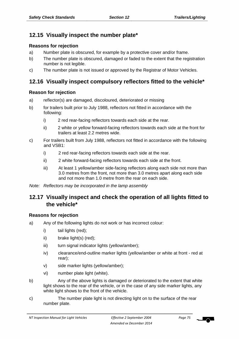
Safety Check Standards Section 12 Trailers/Lighting
NT Inspection Manual for Light Vehicles Effective 2 September 2004
Amended xx December 2014
Page 75
12.15 Visually inspect the number plate*
Reasons for rejection
a) Number plate is obscured, for example by a protective cover and/or frame.
b) The number plate is obscured, damaged or faded to the extent that the registration number is not legible.
c) The number plate is not issued or approved by the Registrar of Motor Vehicles.
12.16 Visually inspect compulsory reflectors fitted to the vehicle*
Reason for rejection
a) reflector(s) are damaged, discoloured, deteriorated or missing
b) for trailers built prior to July 1988, reflectors not fitted in accordance with the following:
i) 2 red rear-facing reflectors towards each side at the rear.
ii) 2 white or yellow forward-facing reflectors towards each side at the front for trailers at least 2.2 metres wide.
c) For trailers built from July 1988, reflectors not fitted in accordance with the following and VSB1:
i) 2 red rear-facing reflectors towards each side at the rear.
ii) 2 white forward-facing reflectors towards each side at the front.
iii) At least 1 yellow/amber side-facing reflectors along each side not more than 3.0 metres from the front, not more than 3.0 metres apart along each side and not more than 1.0 metre from the rear on each side.
Note: Reflectors may be incorporated in the lamp assembly
12.17 Visually inspect and check the operation of all lights fitted to
the vehicle*
Reasons for rejection
a) Any of the following lights do not work or has incorrect colour:
i) tail lights (red);
ii) brake light(s) (red);
iii) turn signal indicator lights (yellow/amber);
iv) clearance/end-outline marker lights (yellow/amber or white at front - red at rear);
v) side marker lights (yellow/amber);
vi) number plate light (white).
b) Any of the above lights is damaged or deteriorated to the extent that white light shows to the rear of the vehicle, or in the case of any side marker lights, any white light shows to the front of the vehicle.
c) The number plate light is not directing light on to the surface of the rear number plate.

Safety Check Standards Section 12 Trailers/Lighting
NT Inspection Manual for Light Vehicles Effective 2 September 2004
Amended xx December 2014
Page 76
d) Any wiring for compulsory lights is frayed or bared or is insecure to the extent that it is likely to be damaged.
e) Lights as follows are not fitted to pre 3rd edition trailers – trailers built prior to July1988 - (dimensions measured at centre of lights):
At front of trailer:
A trailer built prior to July1988 may be fitted with optional, white or yellow/amber clearance/end-outline marker lights (if trailer more than 1.8m wide)
For a trailer built post July1988, Front Position Lamps (showing a white light to the front) are required:
o if a trailer is more than 1600mm wide and over 4000mm long; or
o if a trailer is over 1800mm wide.
o Side Marker Lamps (showing amber light to the front and red light to the rear) may be fitted in lieu of front position lamps.
NOTE: From August 2013, all trailers presented for first registration in the NT must be fitted with front position lamps, as required. Trailers previously registered in the NT prior to August 2013 without compliance with front position lamp requirements may continue to be accepted for NT registration without modification however, all other trailer requirements will continue to apply.
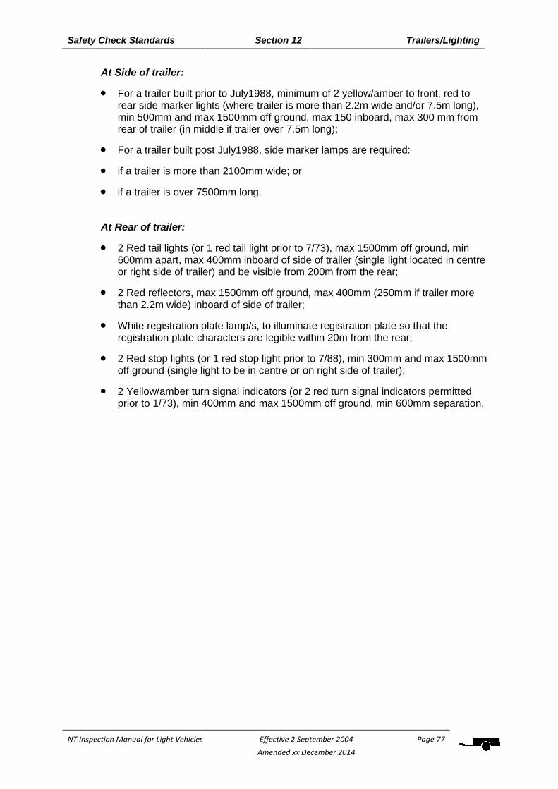
Safety Check Standards Section 12 Trailers/Lighting
NT Inspection Manual for Light Vehicles Effective 2 September 2004
Amended xx December 2014
Page 77
At Side of trailer:
For a trailer built prior to July1988, minimum of 2 yellow/amber to front, red to rear side marker lights (where trailer is more than 2.2m wide and/or 7.5m long), min 500mm and max 1500mm off ground, max 150 inboard, max 300 mm from rear of trailer (in middle if trailer over 7.5m long);
For a trailer built post July1988, side marker lamps are required:
if a trailer is more than 2100mm wide; or
if a trailer is over 7500mm long.
At Rear of trailer:
2 Red tail lights (or 1 red tail light prior to 7/73), max 1500mm off ground, min 600mm apart, max 400mm inboard of side of trailer (single light located in centre or right side of trailer) and be visible from 200m from the rear;
2 Red reflectors, max 1500mm off ground, max 400mm (250mm if trailer more than 2.2m wide) inboard of side of trailer;
White registration plate lamp/s, to illuminate registration plate so that the registration plate characters are legible within 20m from the rear;
2 Red stop lights (or 1 red stop light prior to 7/88), min 300mm and max 1500mm off ground (single light to be in centre or on right side of trailer);
2 Yellow/amber turn signal indicators (or 2 red turn signal indicators permitted prior to 1/73), min 400mm and max 1500mm off ground, min 600mm separation.

This page intentionally left blank

NT Inspection Manual for Light Vehicles Effective 2 September 2004 Page A - 1
Appendix A Checking For Rust

Appendix A Safety Check Standards CHECKING FOR RUST
NT Inspection Manual for Light Vehicles Effective 2 September 2004 Page A - 2
Classification of Rust
The extent of corrosion in a vehicle can range from light surface rust to the total breakdown of parent metal.
Depending on the individual vehicle’s design, there are many different ways in which corrosion can begin and the degree to which a material or structure is attacked can vary widely. In general, though, the formation of rust and resultant loss of metal occurs in areas which retain moisture because (for example) of a build-up of road dirt and mud.
In order to simplify identification and classification when carrying out a motor vehicle inspection, this publication classifies the extent of corrosion in three different stages.
Stage 1 - Surface Rust
Light, powdery corrosion on the surface of a section of metal is termed surface rust and is sometimes the first indication of corrosion that can be observed; it should warn the owner of the vehicle to take steps for preventing the rust from spreading.
Surface rust can occur on or behind any body panel of a vehicle particularly if the protective coating is scratched or damaged.
Stage 2 - Advanced Rust
Surface rust, if left unattended, will develop into an advanced form of corrosion which can usually be seen as an eruption of oxidised metal, either on bare metal or under paint. This eruption occurs because the rust reaction involves an increase in volume so that pitting or bubbling of paint is the usual indication of penetration.
Stage 3 - Extensive Rust
The final stage of the corrosion process is the formation of heavy encrustation of oxidised metal which completely replace the parent metal. This results in a hole or series of holes in the body panel or structural member of the vehicle when the rust is removed. This category of rust can usually only be rectified by replacement of the affected body panels and parts.
Classification of Vehicle Structures
Vehicle structural components can be categorised according to their importance to safety. For instance, subframes and other basic structural sections have to be absolutely free of rust because their failure could make a vehicle difficult to control and might cause it to crash. As already mentioned, such failures will also probably reduce the chances of survival in a crash.
Primary Structure
This category includes any structure or component which, if it collapsed, would make the vehicle uncontrollable or would considerably reduce occupant safety in a crash. Examples of components in this category are illustrated below.
Typical primary structure components
1. Main structural members such as subframes and chassis rails
2. Suspension mountings and parts
3. Steering component mounting points
4. Door sills and pillars
5. Door hinges and latch mounting points

Appendix A Safety Check Standards CHECKING FOR RUST
NT Inspection Manual for Light Vehicles Effective 2 September 2004 Page A - 3
6. Seat anchorage points
7. Seat belt anchorage points
8. All floor panels
9. Boot floor
10. Bulkheads

Appendix A Safety Check Standards CHECKING FOR RUST
NT Inspection Manual for Light Vehicles Effective 2 September 2004 Page A - 4
Secondary Structure
The second category includes any structure or component which, if it collapsed, would not immediately affect a vehicle’s controllability or the protection provided by its built-in safety systems. Normally, surface rust or advanced rust would not be a cause for rejection in these components but extensive rust is usually either hazardous to persons in or near the vehicle because of its sharp edges or because exhaust fumes can get into the vehicle. In such cases, extensive rust, must therefore be rejected. The illustration below shows examples covered by this category.
Typical secondary components
1. Mudguards or fenders
2. Roof
3. Boot lid, bonnet and doors (areas within 100mm of mounting and locking points
are primary structures and must be free of advanced or extensive rust).
4. Exhaust system
NOTE: Because of differing structural designs, it might be difficult to categorise
some vehicle components as primary or secondary structure. Where such difficulties
are encountered, advice should be sought through the MVR Engineering Section to
clarify any uncertainties that might be encountered.
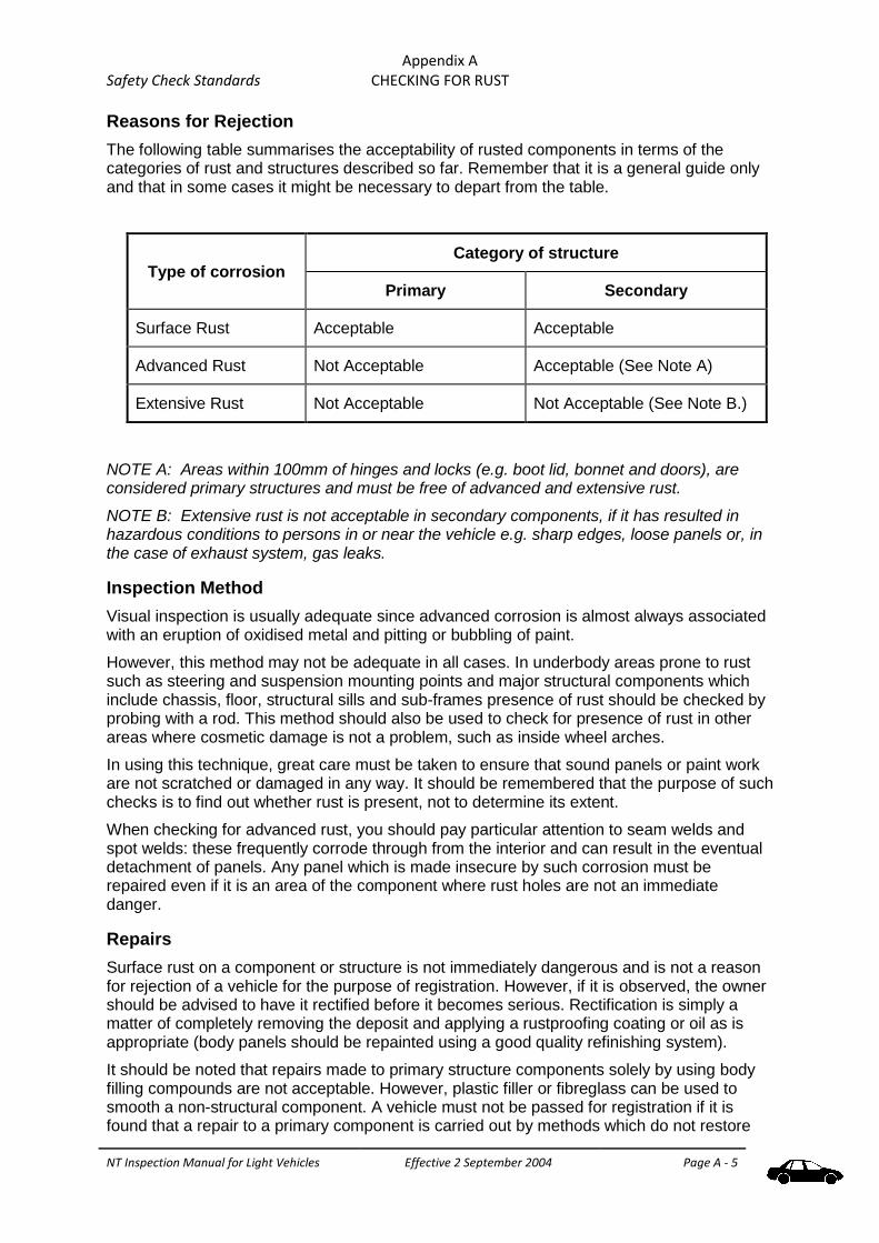
Appendix A Safety Check Standards CHECKING FOR RUST
NT Inspection Manual for Light Vehicles Effective 2 September 2004 Page A - 5
Reasons for Rejection
The following table summarises the acceptability of rusted components in terms of the categories of rust and structures described so far. Remember that it is a general guide only and that in some cases it might be necessary to depart from the table.
Type of corrosion Category of structure
Primary Secondary
Surface Rust Acceptable Acceptable
Advanced Rust Not Acceptable Acceptable (See Note A)
Extensive Rust Not Acceptable Not Acceptable (See Note B.)
NOTE A: Areas within 100mm of hinges and locks (e.g. boot lid, bonnet and doors), are considered primary structures and must be free of advanced and extensive rust.
NOTE B: Extensive rust is not acceptable in secondary components, if it has resulted in hazardous conditions to persons in or near the vehicle e.g. sharp edges, loose panels or, in the case of exhaust system, gas leaks.
Inspection Method
Visual inspection is usually adequate since advanced corrosion is almost always associated with an eruption of oxidised metal and pitting or bubbling of paint.
However, this method may not be adequate in all cases. In underbody areas prone to rust such as steering and suspension mounting points and major structural components which include chassis, floor, structural sills and sub-frames presence of rust should be checked by probing with a rod. This method should also be used to check for presence of rust in other areas where cosmetic damage is not a problem, such as inside wheel arches.
In using this technique, great care must be taken to ensure that sound panels or paint work are not scratched or damaged in any way. It should be remembered that the purpose of such checks is to find out whether rust is present, not to determine its extent.
When checking for advanced rust, you should pay particular attention to seam welds and spot welds: these frequently corrode through from the interior and can result in the eventual detachment of panels. Any panel which is made insecure by such corrosion must be repaired even if it is an area of the component where rust holes are not an immediate danger.
Repairs
Surface rust on a component or structure is not immediately dangerous and is not a reason for rejection of a vehicle for the purpose of registration. However, if it is observed, the owner should be advised to have it rectified before it becomes serious. Rectification is simply a matter of completely removing the deposit and applying a rustproofing coating or oil as is appropriate (body panels should be repainted using a good quality refinishing system).
It should be noted that repairs made to primary structure components solely by using body filling compounds are not acceptable. However, plastic filler or fibreglass can be used to smooth a non-structural component. A vehicle must not be passed for registration if it is found that a repair to a primary component is carried out by methods which do not restore

Appendix A Safety Check Standards CHECKING FOR RUST
NT Inspection Manual for Light Vehicles Effective 2 September 2004 Page A - 6
the original strength of the component or part. (A good way to check for continuity of structure, if a fibreglass repair is suspected, is to run a magnet over the surface.)
Extensive rust in structural members can only be repaired by replacing the affected member or by completely removing all rusted material and reinforcing it so that the original strength of the affected structural member is re-established.
Where a primary structure is found to be in need of repair and the repaired component would normally be coated with a bituminous coating or covered by another vehicle component such as a seat or a floor mat, it is quite in order to ask the owner to resubmit the repaired vehicle before the repairs are obscured so that the adequacy of the repairs can be assessed. A note to this effect should be made on the inspection report if this is required.

NT Inspection Manual for Light Vehicles Effective 2 September 2004 Amended September 2006
Page B - 1
Appendix B Stationary Noise Test

This page intentionally left blank

National Stationary Exhaust Noise Test Procedures for In-Service Motor Vehicles Appendix B
NT Inspection Manual for Light Vehicles Effective 2 September 2004 Amended September 2006
Page B - iii
National Stationary Exhaust
Noise Test Procedures
for
In-Service Motor Vehicles

National Stationary Exhaust Noise Test Procedures for In-Service Motor Vehicles Appendix B
NT Inspection Manual for Light Vehicles Effective 2 September 2004 Amended September 2006
Page B - iv

National Stationary Exhaust Noise Test Procedures for In-Service Motor Vehicles Appendix B
NT Inspection Manual for Light Vehicles Effective 2 September 2004 Amended September 2006
Page B - v
National Transport Commission
National Stationary Exhaust Noise Test Procedures for In-Service Motor Vehicles – September 2006
Report Prepared by: National Transport Commission on behalf of the Land Transport
Environment Committee.
ISBN: 1 921168 50 1

National Stationary Exhaust Noise Test Procedures for In-Service Motor Vehicles Appendix B
NT Inspection Manual for Light Vehicles Effective 2 September 2004 Amended September 2006
Page B - v
FOREWORD
The National Transport Commission (NTC) and the National Environment Protection Council (NEPC) are jointly responsible, through statutory obligations, to develop policy relating to land transport emissions and noise in consultation with each other. This consultation takes place through the Land Transport Environment Committee (LTEC) and this committee includes transport and environmental agencies.
The National Stationary Exhaust Noise Test Procedures (NSENTP) for In-Service Motor Vehicles was first prepared by the Motor Vehicle Environment Committee (MVEC, the precursor to LTEC) in 1999 to introduce a national approach to measuring exhaust noise. Previous to this, some jurisdictions had developed their own approaches and the differences in these approaches could have led to inconsistencies in test results. A nationally uniform approach ensures that vehicle owners will get an accurate assessment of whether their vehicle complies with national noise standards.
The Australian Design Rule (ADR) 83/00 for the external noise of motor vehicles was approved by Ministers in 2003. This new noise emission standard for motor vehicles adopts the UN Economic Commission for Europe (UNECE) Regulations for motor vehicle noise. The UNECE regulations refer to ISO 5130 “Acoustics – Measurement of Sound Pressure Levels Emitted by Stationary Road Vehicles” which provide the noise testing procedures for in-service vehicles. The NSENTP needed to be updated to incorporate elements of ISO 5130.
These test procedures have been approved by the Australian Transport Council and the National Environment Protection Council. They are referred to in the Roadworthiness Guidelines issued under the Australian Vehicle Standard Rules 1999 (Rule 153).
The test procedures should be used by all environment and transport agencies when testing for compliance with Australian Vehicle Standard Rules.
LTEC would like to acknowledge the Environment Protection Authority Victoria for the work in developing this revised draft NSENTP.
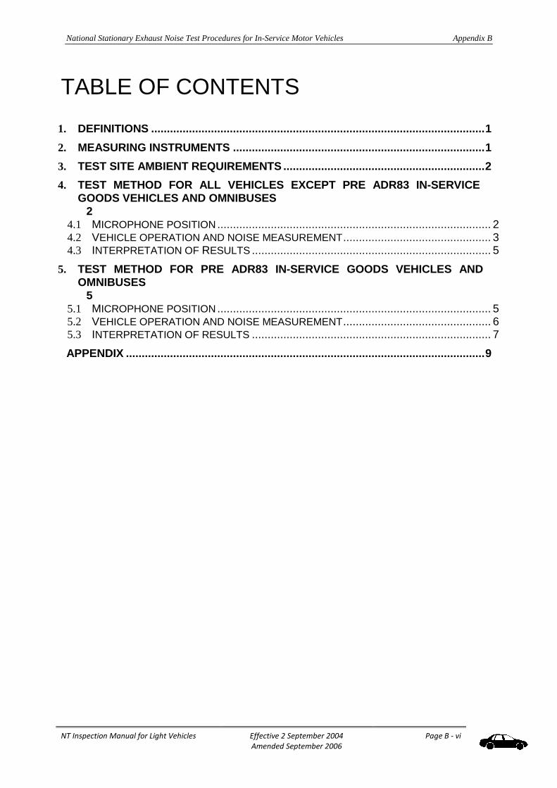
National Stationary Exhaust Noise Test Procedures for In-Service Motor Vehicles Appendix B
NT Inspection Manual for Light Vehicles Effective 2 September 2004 Amended September 2006
Page B - vi
TABLE OF CONTENTS
1. DEFINITIONS .......................................................................................................... 1
2. MEASURING INSTRUMENTS ................................................................................ 1
3. TEST SITE AMBIENT REQUIREMENTS ................................................................ 2
4. TEST METHOD FOR ALL VEHICLES EXCEPT PRE ADR83 IN-SERVICE GOODS VEHICLES AND OMNIBUSES 2
4.1 MICROPHONE POSITION ....................................................................................... 2 4.2 VEHICLE OPERATION AND NOISE MEASUREMENT ............................................... 3 4.3 INTERPRETATION OF RESULTS ............................................................................ 5
5. TEST METHOD FOR PRE ADR83 IN-SERVICE GOODS VEHICLES AND OMNIBUSES 5
5.1 MICROPHONE POSITION ....................................................................................... 5 5.2 VEHICLE OPERATION AND NOISE MEASUREMENT ............................................... 6 5.3 INTERPRETATION OF RESULTS ............................................................................ 7
APPENDIX .................................................................................................................. 9
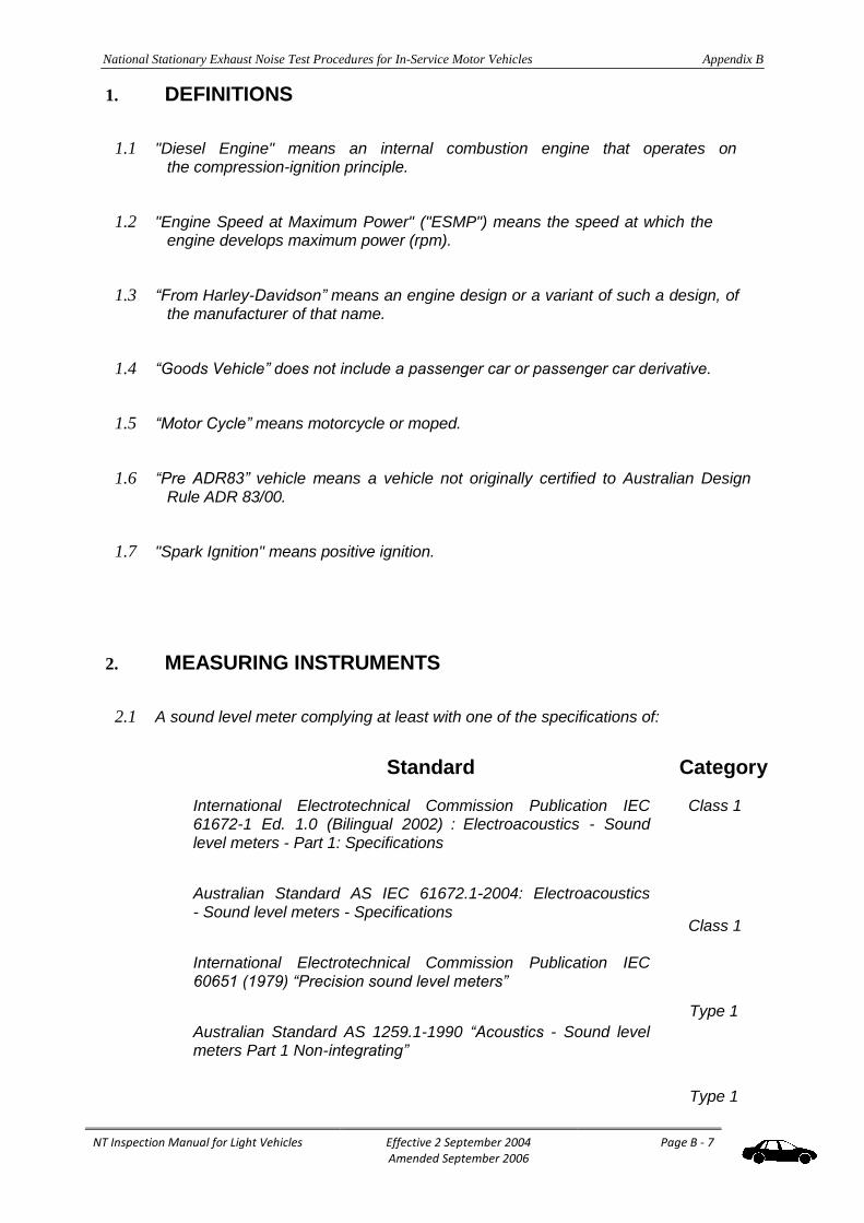
National Stationary Exhaust Noise Test Procedures for In-Service Motor Vehicles Appendix B
NT Inspection Manual for Light Vehicles Effective 2 September 2004 Amended September 2006
Page B - 7
1. DEFINITIONS
1.1 "Diesel Engine" means an internal combustion engine that operates on the compression-ignition principle.
1.2 "Engine Speed at Maximum Power" ("ESMP") means the speed at which the engine develops maximum power (rpm).
1.3 “From Harley-Davidson” means an engine design or a variant of such a design, of the manufacturer of that name.
1.4 “Goods Vehicle” does not include a passenger car or passenger car derivative.
1.5 “Motor Cycle” means motorcycle or moped.
1.6 “Pre ADR83” vehicle means a vehicle not originally certified to Australian Design Rule ADR 83/00.
1.7 "Spark Ignition" means positive ignition.
2. MEASURING INSTRUMENTS
2.1 A sound level meter complying at least with one of the specifications of:
Standard Category
International Electrotechnical Commission Publication IEC 61672-1 Ed. 1.0 (Bilingual 2002) : Electroacoustics - Sound level meters - Part 1: Specifications
Australian Standard AS IEC 61672.1-2004: Electroacoustics - Sound level meters - Specifications
International Electrotechnical Commission Publication IEC 60651 (1979) “Precision sound level meters”
Australian Standard AS 1259.1-1990 “Acoustics - Sound level meters Part 1 Non-integrating”
Class 1
Class 1
Type 1
Type 1

National Stationary Exhaust Noise Test Procedures for In-Service Motor Vehicles Appendix B
NT Inspection Manual for Light Vehicles Effective 2 September 2004 Amended September 2006
Page B - 8
shall be used for measurements of noise levels1. Measurements must be carried out using
frequency weighting “A” and time weighting “F”.
1 Class 2 or Type 2 meters meeting one of the above technical standards may be used for field or conformance
purposes however a tolerance of 2dB(A) must be allowed.

National Stationary Exhaust Noise Test Procedures for In-Service Motor Vehicles Appendix B
NT Inspection Manual for Light Vehicles Effective 2 September 2004 Amended September 2006
Page B - 9
2.2 The sound level meter shall be calibrated against an acoustic calibrator immediately before and after each series of tests of each vehicle tested. If the meter readings obtained from these calibrations differ by more than ldB(A) the test shall be considered invalid.
2.3 The rotational speed of the engine shall be measured by either an external tachometer whose accuracy is within 3 percent or where fitted, the vehicle’s tachometer.
3. TEST SITE AMBIENT REQUIREMENTS
3.1 The measurements shall be made in the open air where both the ambient and wind noise levels are at least 10dB(A) below the noise level being measured.
The site may take the form of an open space or beneath a canopy if no part of the canopy or its supports is within 3 metres of the microphone being used in the test.
The test site within 3 metres of the microphone(s) must be substantially flat and may include kerbs, channels, gutter, poles or other objects not providing excessive acoustic reflection provided that no such object is within 1 metre of the microphone.
3.2 Measurements shall not be made under adverse weather conditions unless the test site is located beneath a canopy meeting the requirements of 3.1 above. Any sound peak that appears to be unrelated to the characteristics of the vehicle shall be ignored in taking the readings. If a windscreen is used, its influence on the sensitivity and the directional characteristics of the microphone shall be taken into account.
3.3 Whilst testing is in progress no person other than any occupants of the vehicle or, in the case of a motor cycle, the rider, shall be within 1 metre of the microphone in use. No person or object other than the testing officer and an observer or the objects necessary for the performance of the test shall be within 3 metre of the microphone in use.

National Stationary Exhaust Noise Test Procedures for In-Service Motor Vehicles Appendix B
NT Inspection Manual for Light Vehicles Effective 2 September 2004 Amended September 2006
Page B - 10
4. TEST METHOD FOR ALL VEHICLES EXCEPT PRE ADR83 IN-SERVICE GOODS VEHICLES AND OMNIBUSES
4.1 Microphone position
4.1.1 The microphone shall be directed towards the orifice of the exhaust outlet and shall be supported by a tripod or similar device not providing excessive acoustic reflection. The general requirements for positioning microphones are shown in the Appendix.
4.1.2 The nominal axis of maximum sensitivity of the microphone shall be substantially parallel to the test site surface and shall make an angle of 45 degrees ±10 degrees with the principal direction of gas flow from the exhaust.
4.1.3 In selecting the 45 degree alignment from the outlet of a motor vehicle fitted with two or more outlets, only the angle resulting in the microphone being farthest from any other outlet must be used.

National Stationary Exhaust Noise Test Procedures for In-Service Motor Vehicles Appendix B
NT Inspection Manual for Light Vehicles Effective 2 September 2004 Amended September 2006
Page B - 11
4.1.4 The height of the microphone above the test site surface shall be equal to that of the orifice of the exhaust outlet ±25mm but shall not be less than 200mm above the test site surface.
4.1.5 The distance of the microphone from the exhaust outlet orifice shall be 500mm±25mm.
4.1.6 In the case of a vehicle fitted with a vertical exhaust, the microphone shall be placed at the height of the exhaust outlet, oriented upwards with its axis vertical. It shall be placed at a distance of 500mm ±25mm from the side of the vehicle nearer to the outlet.
4.1.7 For vehicles fitted with one exhaust outlet the microphone shall be placed so that the greatest possible distance is achieved between it and the vehicle.
4.1.8 For vehicles fitted with two or more exhaust outlets spaced less than 300mm apart only one microphone position shall be used. That position shall be selected in accordance with the procedure described in the preceding paragraphs in respect of an exhaust outlet that results in the greatest possible distance from the vehicle or where this does not exist, to the outlet that is highest above the ground.
4.1.9 For vehicles fitted with two or more exhaust outlets spaced more than 300mm apart, each exhaust outlet shall be treated separately as if it were the only one.
4.1.10 Notwithstanding anything to the contrary in the preceding paragraphs if the microphone positioning procedures result in no suitable position due to an obstruction being part of the vehicle or in an obstruction being directly between the microphone and the exhaust outlet, the requirements of paragraphs 4.1.2, 4.1.3 and 4.1.5 may be varied provided the distance from the outlet to the microphone is not less than 500mm±25mm.
4.1.11 Despite the preceding paragraphs if the microphone is to be placed so that it is less than 500mm from the engine then the angle between the direction of gas flow and the angle of the nominal maximum sensitivity of the microphone may be altered so that the microphone is more than 500mm from the engine.

National Stationary Exhaust Noise Test Procedures for In-Service Motor Vehicles Appendix B
NT Inspection Manual for Light Vehicles Effective 2 September 2004 Amended September 2006
Page B - 12
4.2 Vehicle operation and noise measurement
4.2.1 The vehicle shall be stationary with the transmission in “neutral” or, in the case of a vehicle with automatic transmission, with the gear selector in the “park” position if such a position is provided. In the case of a motor cycle, the vehicle shall be held in a substantially vertical position. In the case of a motor cycle having no neutral gear position, measurements shall be carried out with the rear wheel raised off the ground.
4.2.2 Before the measurements are begun, the testing officer shall ensure that the engine of the vehicle under test is sufficiently warm to allow the noise testing to be carried out.

National Stationary Exhaust Noise Test Procedures for In-Service Motor Vehicles Appendix B
NT Inspection Manual for Light Vehicles Effective 2 September 2004 Amended September 2006
Page B - 13
4.2.3 The engine of the vehicle under test shall be operated in accordance with one of the following procedures:
4.2.3.1 Where the ESMP for that engine has been determined by the testing authority the engine shall be brought to and stabilised at a speed as close as the testing officer can achieve to:
(i) ½ ESMP in the case of a pre ADR83 motor cycle
(ii) ½ ESMP in the case of any other motor cycle where the ESMP is more than 5000 rpm; or
(iii) ¾ ESMP in the case of any other vehicle.
4.2.3.2 Where the engine speed has been governed by the manufacturer and ¾ ESMP cannot be achieved, the test speed shall be 5% below the maximum governed speed.
4.2.3.3 Where the ESMP for that engine has not been determined by the testing authority then the engine shall be brought to and stabilised at a speed as close as the testing officer can achieve to one of the following speeds:
In the case of a passenger car or derivative, if the engine has:
(i) 5 cylinders or less 4000 rpm
(ii) 6 cylinders and is manufactured before 1995 3200 rpm
manufactured in 1995 or later 3600 rpm
(iii) 8 cylinders and is
manufactured before 2000 3300 rpm
manufactured in 2000 or later 3900 rpm
(iv) more than 8 cylinders 4300 rpm
(v) If the engine is a rotary engine 4500 rpm
In the case of a motor cycle:
(i) for a two-stroke engine 3750 rpm
(ii) for a four-stroke engine:
from Harley Davidson 2500 rpm
from any other manufacturer 3000 rpm
In the case of a goods vehicle or bus, if the engine has:
(i) 6 cylinders or more 3000rpm
(ii) 4 cylinders and is
manufactured before 1970 2500rpm
manufactured in 1970 or later 3500rpm

National Stationary Exhaust Noise Test Procedures for In-Service Motor Vehicles Appendix B
NT Inspection Manual for Light Vehicles Effective 2 September 2004 Amended September 2006
Page B - 14
4.2.3.4 Where, in the opinion of the testing officer, the test speed determined by reference to the above is not attainable by the engine then at the maximum speed that the testing officer believes that the engine can be safely tested.
4.2.4 A noise level measurement shall then be made. The noise level shall be the maximum level measured between the stabilised test speed and when the throttle is swiftly returned to idle position.

National Stationary Exhaust Noise Test Procedures for In-Service Motor Vehicles Appendix B
NT Inspection Manual for Light Vehicles Effective 2 September 2004 Amended September 2006
Page B - 15
4.2.5 The specified procedure shall be repeated until a least three consecutive readings are obtained, each within a range of 1dB(A). For the purposes of this sub-paragraph only, non-integer decibel readings are to be rounded downwards to the nearest whole decibel.
4.3 Interpretation of results
4.3.1 Where one microphone position is used the noise level of the vehicle shall be the arithmetic mean of the readings specified in paragraph 4.2.4 prior to any rounding process.
4.3.2 When the noise level of the vehicle has been calculated, non-integer results shall be conventionally rounded to the nearest whole decibel.
4.3.3 Where more than one microphone position is used the noise level at each microphone position shall be determined as if it were the only one as described in 4.3.1. The noise level of the vehicle shall be the higher or highest noise level so calculated.
4.3.4 In the case of a pre ADR83 vehicle, if the microphone position is less than 1 metre from the engine compartment of the vehicle the calculated noise level shall be reduced by 2dB(A). Alternately if the mechanical noise of a pre ADR83 vehicle (for example engine or transmission noise) can be shown to increase the measured noise level by 2dB(A) or more, special acoustic shielding may be fitted to mask this source so that the test is carried out on the exhaust noise alone.
5. TEST METHOD FOR PRE ADR83 IN-SERVICE GOODS VEHICLES AND OMNIBUSES
5.1 Microphone position
5.1.1 The microphone shall be directed towards the orifice of the exhaust outlet and shall be supported by a tripod or similar device not providing excessive acoustic reflection. The general requirements for positioning microphones are shown in the Appendix.
5.1.2 The nominal axis of maximum sensitivity of the microphone shall be substantially parallel to the test site surface.
5.1.3 The height of the microphone above the test site surface shall be equal to that of the orifice of the exhaust outlet ±25mm but shall not be less than 200mm above the test site surface.

National Stationary Exhaust Noise Test Procedures for In-Service Motor Vehicles Appendix B
NT Inspection Manual for Light Vehicles Effective 2 September 2004 Amended September 2006
Page B - 16
The distance of the microphone from the orifice of the exhaust outlet shall be 1050mm
±50mm.
5.1.5 For vehicles fitted with one exhaust outlet that is at a height above the test site surface of less than 1500mm, the nominal axis of maximum sensitivity of the microphone shall make an angle of 45 degrees ±10 degrees with the principal direction of the gas flow from the exhaust outlet. In selecting this microphone position the microphone

National Stationary Exhaust Noise Test Procedures for In-Service Motor Vehicles Appendix B
NT Inspection Manual for Light Vehicles Effective 2 September 2004 Amended September 2006
Page B - 17
shall be placed so that the greatest possible distance is achieved between it and the vehicle.
5.1.6 For vehicles fitted with one exhaust outlet that is at a height above the test site surface of at least 1500mm, the nominal axis of maximum sensitivity of the microphone shall make an angle of 90 degrees ±10 degrees with the longitudinal centreline of the vehicle. However, if positioning the microphone according to the preceding requirement would result in the microphone being placed in the gas flow from the exhaust outlet then the microphone location may be rotated, in a horizontal plane, no greater than 45 degrees. In selecting this microphone position the microphone shall be placed so that the greatest possible distance is achieved between it and the vehicle.
5.1.7 For vehicles fitted with two or more exhaust outlets spaced less than 500mm apart and connected to a single silencer only one microphone position shall be used. That position shall be selected in accordance with the procedure described in the preceding paragraphs in respect of an exhaust outlet that results in the microphone being at the greatest possible distance from the vehicle.
5.1.8 For vehicles fitted with two or more exhaust outlets connected to separate silencers or spaced more than 500mm apart, each exhaust outlet shall be treated separately as if it were the only one.
5.1.9 Notwithstanding anything to the contrary in the preceding paragraphs if the microphone positioning procedures result in no suitable position due to an obstruction being part of the vehicle or in an obstruction being directly between the microphone and the exhaust outlet, the requirements of paragraphs 5.1.2 and 5.1.3 may be varied.
5.2 Vehicle operation and noise measurement
5.2.1 The vehicle shall be stationary with the transmission in "neutral" or, in the case of a vehicle with automatic transmission, with the gear selector in the "park" position if such a position is provided.
5.2.2 Before the measurements are begun, the testing officer shall ensure that the engine of the vehicle under test is sufficiently warm to allow the noise testing to be carried out.
5.2.3 In the case of goods vehicles and omnibuses powered by a diesel engine the engine shall be operated in accordance with the following procedure.

National Stationary Exhaust Noise Test Procedures for In-Service Motor Vehicles Appendix B
NT Inspection Manual for Light Vehicles Effective 2 September 2004 Amended September 2006
Page B - 18
5.2.3.1 With the engine at idling speed the accelerator pedal of the vehicle shall be depressed as rapidly as possible and kept fully depressed until the speed of the engine is substantially stable at maximum (or governed) speed. The accelerator pedal shall then be permitted to return to its original position as rapidly as possible and left in that position until the engine has returned to idling speed.
5.2.3.2 A noise level measurement shall be made for each microphone position in use by noting the maximum noise level indicated during this procedure.

National Stationary Exhaust Noise Test Procedures for In-Service Motor Vehicles Appendix B
NT Inspection Manual for Light Vehicles Effective 2 September 2004 Amended September 2006
Page B - 19
5.2.4 In the case of goods vehicles and omnibuses powered by a spark ignition engine the engine shall be operated in accordance with one of the following procedures.
5.2.4.1 Where the ESMP for that engine has been determined by the testing authority, the engine shall be brought to and stabilised at a speed as close to
¾ ESMP as the testing officer can achieve; or
5.2.4.2 Where the ESMP has not been determined for that engine by the testing authority, then the engine shall be brought to and stabilised at as close as the testing officer can achieve to one of the following speeds:
If the engine has:
(i) 6 cylinders or more 3000rpm
(ii) 4 cylinders and is manufactured before 1970 2500rpm
manufactured in 1970 or later 3500rpm
5.2.4.3 Where, in the opinion of the testing officer, the speed determined by reference to the above is not attainable by the engine then at the maximum speed that the testing officer believes that the engine can be safely tested.
5.2.4.4 A noise level measurement shall then be made.
5.2.5 The specified procedure shall be repeated until a least three consecutive readings are obtained, each within a range of 1dB(A). For the purposes of this sub-paragraph only, non-integer decibel readings are to be rounded downwards to the nearest whole decibel.
5.3 Interpretation of results
Results shall be interpreted as in section 4.3.

National Stationary Exhaust Noise Test Procedures for In-Service Motor Vehicles Appendix B
Appendix B Page 8 Effective September 2006
APPENDIX (Informative)
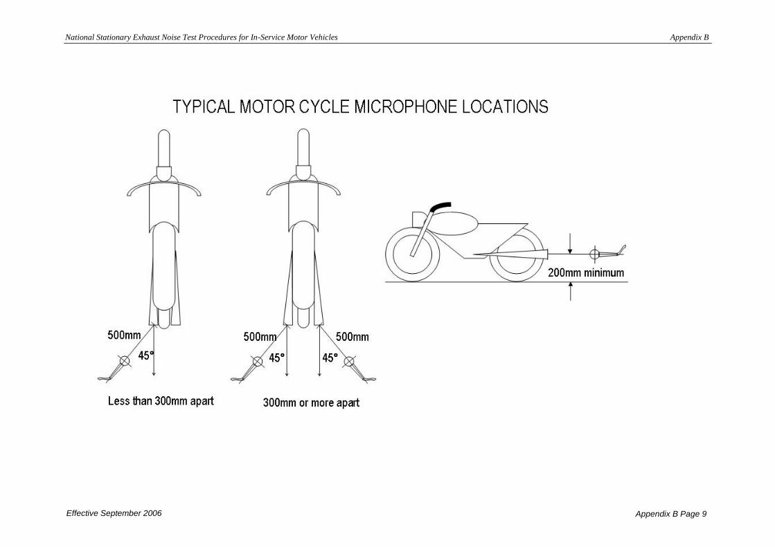
National Stationary Exhaust Noise Test Procedures for In-Service Motor Vehicles Appendix B
Effective September 2006 Appendix B Page 9

National Stationary Exhaust Noise Test Procedures for In-Service Motor Vehicles Appendix B
Effective September 2006 Appendix B Page 10

National Stationary Exhaust Noise Test Procedures for In-Service Motor Vehicles Appendix B
Effective September 2006 Appendix B Page 11

National Stationary Exhaust Noise Test Procedures for In-Service Motor Vehicles Appendix B
Effective September 2006 Appendix B Page 12

National Stationary Exhaust Noise Test Procedures for In-Service Motor Vehicles Appendix B
Effective September 2006 Appendix B Page 13

National Stationary Exhaust Noise Test Procedures for In-Service Motor Vehicles Appendix B
Effective September 2006 Appendix B Page 14

NT Inspection Manual for Light Vehicles Effective 2 September 2004
Amended September 2006
Page B - 15

NT Inspection Manual for Light Vehicles Effective 2 September 2004 Amended 10 April 2012
Page C - 1
Appendix C Special Equipment
Technical Specifications Appendix C Special Equipment List - General
NT Inspection Manual for Light Vehicles Effective 2 September 2004 Amended 10 April 2012
Page C - 2
Equipment list - General
To enable inspections of light vehicles to be carried out in accordance with the procedures detailed in this manual, an Authorised Inspection Station must have a minimum of the following items:
A pit or hoist with adequate lighting for inspection under vehicles.
Garage type jacks to raise vehicles to enable inspection of suspension components for wear or damage.
A recognised brake testing machine as detailed in appendices C1, C2 or C3 or; a suitable sealed area of roadway etc for the testing of brakes as per Section 1.8 - Road Testing of Service Brakes.
A headlight-testing screen constructed in accordance with Appendix C6 or, a suitable headlight-testing device as detailed in appendix C5.
Applicable safety equipment as required for a mechanical workshop and complying with current national Work Health and Safety legislation.

Technical Specifications Appendix C Special Equipment List
NT Inspection Manual for Light Vehicles Effective 2 September 2004 Amended 10 April 2012
Page C - 3
Technical Specifications
Portable Brake Testing Decelerometer C1
Skid Plate Brake Testing Machine C2
Roller Brake Testing Machine C3
Light Transmittance Meter C4
Headlight Aim Tester C5
Headlight Testing Screen C6

Technical Specifications Appendix C1 Portable Brake Testing Decelerometer
NT Inspection Manual for Light Vehicles Effective 2 September 2004 Amended 10 April 2012
Page C - 4
1 Scope
1.1 This specification establishes the requirements for a device which, when placed in a vehicle, will give a reading of its brake deceleration capability during a specified test.
2 General Requirements
2.1 The device shall be portable, lightweight and robust with a mass preferably not exceeding 5 kg.
2.2 The device shall be completely self-contained. Any power source must be internal to the device.
2.3 To eliminate the possibility of a false reading being produced because of a low reserve within an internal energy source, there must be a means to indicate to the operator either that a power supply is in a low state of charge; an automatic disabling function or some other means to preclude incorrect operation.
2.4 The device or its sensors, if separate from the main body, shall be capable of remaining stationary in its test recording position when subjected to a 1.5g deceleration in the horizontal direction.
2.5 The device shall be capable of testing any motor vehicle with the exception of a motorcycle.
2.6 The device shall be capable of providing an original and duplicate copy of the recorded results on a paper tape, card etc. The print media must remain legible for a period of 12 months.
2.7 The device shall have an in-built clock which records the time and date of test. The clock may only be factory set. A facility to allow for "daylight saving" hours is optional.
2.8 The device shall be capable of recording a brake pedal force of up to 1000N + 2%.
2.9 The device shall have an alpha/numeric keyboard to enter various items of vehicle data.
2.10 The device shall report the peak and average deceleration over the range of 0 to 1g with and accuracy of 5% of full scale and an output resolution of 1%.
The period of time over which average deceleration shall be calculated is defined by either of the following:
a) Start of averaging period - within 0.1g of the vehicle starting to decelerate. End of averaging period - not earlier than 0.1g of the vehicle coming to rest.
b) A charge in velocity of either 15 km/hr or 30 km/hr as appropriate (see paragraph 5.1) is achieved.
2.11 The device shall not be capable of proceeding with a test without having the items detailed in specifications 3.1 and 3.2 entered into the machine in the first instance.

Technical Specifications Appendix C1 Portable Brake Testing Decelerometer
NT Inspection Manual for Light Vehicles Effective 2 September 2004 Amended 10 April 2012
Page C - 5
3 Operator Inputs
3.1 The device shall allow the operator to record a vehicle identifier consisting of at least seven alpha/numeric characters.
3.2 The device shall allow the operator to record a personal identification number, otherwise known as the "Examiner's No.", consisting of up to seven alpha/numeric characters.
4 Device Outputs
4.1 An original and duplicate copy of the results shall be printed.
4.2 The device shall print:
i) The peak and average deceleration.
ii) The serial number of the machine as allocated by its manufacturer.
iii) The date when the device must next be calibrated, prefaced with the title "Next Cal".
iv) The time and date of the test.
v) The vehicle identifier.
vi) The maximum brake pedal force during the test.
vii) The examiner's number.
viii) A line space prefaced with the word "signature".
4.3 The device may display the peak and average decelerations.
4.4 The device may display the pedal force applied during the test.
5 Additional information
5.1 The test of brake deceleration capability is taken from a nominal 30 km/hr for the service braking system and 15 km/hr for the emergency (parking) brake system.
5.2 The maximum allowable brake pedal force on a motor vehicle is 885N.
5.1 The items detailed in specifications 3 and 4 are the minimum necessary. Other inputs or outputs are optional.

Technical Specifications Appendix C2 Skid Plate Brake Testing Machine
NT Inspection Manual for Light Vehicles Effective 2 September 2004 Amended 10 April 2012
Page C - 6
1 Scope
1.1 This specification sets the requirements for skid-plate or other drive-over platform type brake testing machines. It describes machines which are suitable for testing vehicles up to 5.0 tonnes tare.
2 General Requirements
2.1 The machine shall be capable of accepting vehicles with a wheel track of at least 750mm to 2000mm.
2.2 If the machine is designed to test two axles at the same time, it should be capable of accepting vehicles with a wheelbase of at least 2000mm to 4000mm. If this requirement is not met, the machine shall be capable of indicating to the operator an invalid test and to report the test on each axle group independently.
2.3 Independent readings of braking force shall be measured at each side of a vehicle.
2.4 Plates shall have a co-efficient of friction of at least 0.6 when measured in combination with dry, original equipment tyres.
2.5 The machine shall be capable of repeatedly supporting an axle load of 3.5 tonnes without damage.
2.6 The machine shall report the peak and average deceleration over the range of 0 to 1g with an accuracy of 5% of full scale and an output resolution of 1%. The period of time over which average deceleration shall be calculated is defined by either of the following:
a) start of averaging period - within 0.1g of the vehicle starting to decelerate; end of averaging period - not earlier than 0.1g of the vehicle coming to rest;
b) a change in velocity from the instant the brakes are applied to zero.
2.7 The manufacturer's recommended test speed shall be indicated on the machine and visible to the vehicle operator in letters not less than 50mm high. If the recommended test speeds for service and emergency brakes are different, both speeds shall be indicated on the machine.
2.8 The machine shall be capable of providing an original and duplicate copy of the results on a paper tape, card etc. The print media must remain legible for a period of 12 months.
2.9 The machine shall have an in-built clock which records the time and date of the test. The clock may only be factory set. A facility to allow for "daylight saving" hours is optional.
2.10 The machine shall be capable of recording a brake pedal force of up to 1000N + 2%. The brake pedal force may be measured with a device separate from the machine, in which case the machine shall be designed such that it will not print the brake performance report until the pedal force is entered in it.
2.11 The machine shall have an alpha/numeric keyboard to enter various items of vehicle data.
2.12 The machine shall not be capable of proceeding with a test without having the items detailed in specifications 3.1 and 3.2 entered into it in the first instance.
3 Operator Inputs
3.1 The machine shall allow the operator to record a vehicle identifier consisting of at least seven alpha/numeric characters.

Technical Specifications Appendix C2 Skid Plate Brake Testing Machine
NT Inspection Manual for Light Vehicles Effective 2 September 2004 Amended 10 April 2012
Page C - 7
3.2 The machine shall allow the operator to record a personal identification number, otherwise known as the Examiner's No." consisting of up to seven alpha/numeric characters.
4 Device Outputs
4.1 An original and duplicate copy of the results shall be printed.
4.2 The machine shall print:
i) The peak and average deceleration.
ii) The percentage difference in brake force between each axle.
iii) The serial number of the machine as allocated by its manufacturer.
iv) The date when the machine must next be calibrated, prefaced with the title "Next Cal".
v) The time and date of the test.
vi) The vehicle identifier.
vii) The maximum brake pedal force during the test.
viii) The examiner's number
ix) A line space prefaced with the word "signature".
5 Additional information
5.1 The maximum allowable brake pedal force on a motor vehicle is 885N.
5.2 The items detailed in specifications 3 and 4 are the minimum necessary. Other inputs or outputs are optional.

Technical Specifications Appendix C3 Roller Brake Testing Machine
NT Inspection Manual for Light Vehicles Effective 2 September 2004 Amended 10 April 2012
Page C - 8
1 Scope
1.1 This specification sets the requirements for roller brake testing machines used in Authorised Inspection Stations.
1.2 There are two categories of machines referred to in this specification. Machines classed as light vehicle testers are suitable for vehicles up to 5.0 tonnes tare and heavy vehicle testers are suitable for vehicles above that mass. Some machines might be designed to test both categories of vehicles.
2 General Requirements
2.1 The machine shall measure braking force at the tyre periphery. Independent readings of braking force at each side of the vehicle shall be provided.
2.2 Braking force readings shall be displayed, whilst they are being generated, which can be clearly seen by the operator of the vehicle.
2.3 Roller sets shall be designed to be mounted into the floor of the inspection area. The frame of the testing machine shall be mounted flush with the floor level in such a manner that a vehicle shall remain substantially level when under test.
2.4 Light vehicle testing machines shall accept under load wheel sizes from 450mm diameter (10" nominal rim diameter) and heavy vehicle testing machines from 600mm diameter (14" nominal rim diameter). This may be met by adjustable spacing between rollers provided such adjustment is possible to achieve in not more than 5 seconds and without the use of tools.
2.5 The distance between the outer and inner roller edges shall be:
Outer Inner
Light machines 2000mm min 750mm max
Heavy machines 2700mm min 750mm max
2.6 Rollers shall be given a co-efficient of friction of not less than 0.6 when measured in combination with dry, original equipment tyres.
2.7 If the rotational speed of the testing machine's roller exceeds 0.5 km/h, the rollers shall be coated with coarse grit embedded in a durable plastic matrix.
2.8 Both rollers in each pair of rollers on each side of the brake testing machine shall be coupled together by appropriate gearing and shall be positively driven.
2.9 Light vehicle testing machines shall be capable of repeatedly supporting an axle load of 3.5 tonnes without damage and heavy vehicle testing machines 13 tonnes.
2.10 If the rotational speed of the rollers exceeds 0.5km/h, the machine should have means of automatic switch-off of power to the rollers when a pre-determined level of slip occurs between the rollers and the tyres of the tested vehicle.
2.11 Braking force measurements shall be displayed in kilonewtons (kN).
2.12 Light vehicle testing machines shall be capable of measuring a braking force on each brake of at least 4kN and heavy testing machines at least 10kN.
NOTE: These forces are the minimum required for inspection purposes. Some vehicle braking systems can achieve several times these braking forces and therefore the machine should be capable of sustaining higher forces without damage.

Technical Specifications Appendix C3 Roller Brake Testing Machine
NT Inspection Manual for Light Vehicles Effective 2 September 2004 Amended 10 April 2012
Page C - 9
2.13 The indicated braking force shall be within + 2% up to 5kN and + 5% above 5kN.
2.14 The machine shall be capable of providing an original and duplicate copy of the results on a paper tape, card, etc. The print media must remain legible for a period of 12 months.
2.15 The machine shall have an in-built clock which records the time and date of the test. The clock may only be factory set. A facility to allow for "daylight saving" hours is optional.
2.16 The machine shall be capable of recording a brake pedal force of up to 1000N + 2%.
2.17 The machine shall have an alpha/numeric keyboard to enter various items of vehicle data.
2.18 The machine shall not be capable of proceeding with a test without having the items detailed in specifications 3.1 and 3.2 entered into it in the first instance.
3 Operator Inputs
3.1 The machine shall allow the operator to record a vehicle identifier consisting of at least seven alpha/numeric characters.
3.2 The machine shall allow the operator to record a personal identification number, otherwise known as the "Examiner's No.", consisting of up to seven alpha/numeric characters.
4 Device Outputs
4.1 An original and duplicate copy of the results shall be printed.
4.2 The machine shall print:
i) The brake and drag force* on each wheel.
ii) The percentage difference in brake force between each axle.
iii) The serial number of the machine as allocated by its manufacturer.
iv) The date when the machine must next be calibrated, prefaced with the title "Next Cal".
v) The time and date of the test.
vi) The vehicle identifier.
vii) The examiner's number.
viii) A line space prefaced with the word "signature".
* (the drag force is that produced by items such as loaded wheel bearings or brake shoes in contact with the drum when the service system is not energised.)
5 Additional Information
5.1 The maximum allowable brake pedal force on a motor vehicle is 885N.
5.2 The items detailed in specifications 3 and 4 are the minimum necessary. Other inputs or outputs are optional.

Technical Specifications Appendix C4 Light Transmittance Meter
NT Inspection Manual for Light Vehicles Effective 2 September 2004 Amended 10 April 2012
Page C - 10
1 Scope
1.1 This specification sets the requirements for a device to measure the light transmittance of vehicle windows. The principal intention is to obtain the transmittance when the glass is covered with a tinted plastic media.
2 General Requirements
2.1 The device shall be portable, lightweight, robust and completely self-contained (i.e. have its own energy source).
2.2 To eliminate the possibility of a false reading being produced because of a low reserve within an internal energy source, there must be a means to indicate to the operator either that a power supply is in a low state of charge; an automatic disabling function of some other means to preclude incorrect operation.
2.3 The device shall be in two main components - a light source and receiver.
2.4 If the light source and receiver are connected by a wire, the wire shall be at least long enough to reach from the centre of the inside of a car windscreen to the centre of the opposite side.
2.5 The receiver shall have a digital or analogue display to indicate the light transmittance of the sample test. A peak hold facility is preferable.
2.6 The display shall indicate a figure of 100% when the light source is brought into the test position without a test sample in place. All other readings with a sample under test shall be in proportions of that 100% with a resolution of 1%.
2.7 The accuracy of the transmittance reading shall be within 5% of full scale over the range of 20% to 100%.
2.8 The light source shall be an incandescent filament source at a nominal colour temperature of 2856ºK representing illuminant A of the International Commission on Illumination (C.I.E.). The voltage to the lamp shall be stabilised within + 0.1%.
2.9 The receiver shall have a relative spectral sensitivity conforming to photopic curve V
( ) of relative luminous efficiency of the C.I.E. 1931 standard observer for photopic vision.
2.10 There shall be a unique serial number of the device as issued by its manufacturer.
3 Additional Information
3.1 The minimum requirements for light transmission of automotive glazing are in general:
Windscreen 75%
Front side windows 35%
Windows to the rear of the driver 15%

Technical Specifications Appendix C5 Headlight Aiming Tester
NT Inspection Manual for Light Vehicles Effective 2 September 2004 Amended 10 April 2012
Page C - 11
1 Introduction
1.1 The Rules for Authorised Inspection Stations permit the use of approved headlight aim testers for checking the aim of vehicle headlights.
1.2 Headlight aim testers complying with the requirements of this specification are acceptable for the testing of the aim of vehicle headlights in accordance with those Rules.
1.3 This specification is restricted to headlight aim testers that employ a collimating lens: it does not apply to testers which use other methods of testing headlight aim.
2 Definitions
2.1 Unless otherwise stipulated, angles given in this specification refer to the included angle between the line drawn from the headlight centre to the intersection of the calibration screen axes and the line drawn from the headlight centre to the point of intersection of either the horizontal or vertical axis of the screen with the required respective vertical or horizontal line.
2.2 Headlight - A lighting source mounted on a vehicle to provide illumination of the road and objects ahead of a vehicle.
2.3 Hot Spot - The zone of the headlight beam which is of highest intensity as it appears to an observer viewing the beam on an image screen. For headlights with European beams or where the beam has a sharp angular cut-off, the top of the hot spot shall be taken as the “elbow point” or intersection of the horizontal and inclined cut-off zones.
2.4 HV Point - The intersection of the central horizontal axis (H) and the central vertical axis (V) of the image screen.
2.5 Vertical Median Plane - The plane passing through the longitudinal centre line of the vehicle, perpendicular to the plane on which the vehicle is standing.
2.6 h - The vertical height of the centre of the headlight above the plane supporting the vehicle ( in millimetres ).
3 General Requirements
3.1 The headlight aim tester shall consist of a lens which focuses the light beam onto a screen within the tester.
3.2 The screen shall be located in a position that will allow the operator of the tester to readily and conveniently see the image of the headlight’s light beam.
3.3 Provision shall be made for immediate adjustment to allow for different headlight heights and vehicle orientations.
3.4 The tester shall be mounted on at least one securely mounted locating guide rail which traverses the inspection lane and shall be easily movable to any point along this rail. The track followed by the tester (whether consisting of two rails, or one rail and a prepared surface) shall be such that the tester is always correctly aligned in the vertical plane.
3.5 Aiming of the tester shall be accomplished by either an electrical or mechanical device. If an electrical aiming device is provided, a back-up mechanical aiming device shall also be provided.
4 Design Requirements
Optical Characteristics

Technical Specifications Appendix C5 Headlight Aiming Tester
NT Inspection Manual for Light Vehicles Effective 2 September 2004 Amended 10 April 2012
Page C - 12
4.1 Headlight aim testers shall enable the headlight beam pattern to be examined on an image screen within the device. The resulting image must be equivalent to that which would be projected onto a flat screen placed in front of the headlight lens at a horizontal distance nominated by the manufacturer (D metres ).-
4.2 The focused beam on the image screen shall be accurate to within 0.25 degree in the vertical direction at all declinations from horizontal to 3.25 degrees below horizontal.
Image Screen
The image screen shall have grid lines provided to assist aiming of headlights,
comprising:
4.3 A central horizontal and a central vertical axis which intersect on the optical axis of the collimating lens, at the HV point.
4.4 A series of evenly spaced horizontal lines which allows estimation of angular declination below the HV point in the range 0 to 3.25 degrees with a spacing not more than 0.25 degrees. They must be labelled in degrees, or mm declination as measured on an equivalent flat screen as specified in specification 4.1.
4.5 A straight line inclined at 15 degrees to the horizontal axis for testing the aim of asymmetric European or Z-beam type headlights. The line shall originate at the intersection of the vertical axis and the horizontal line 0.5 degrees below the horizontal axis and shall project upwards and to the left of the point of origin.
4.6 The requirements of specification 4.2 may be met by movement of the horizontal axis by an external calibrated mechanism which indicates the equivalent angles of declination.
Device Alignment
4.7 The device shall be provided with an indicator or other means to enable an operator to locate rapidly the approximate centre of the headlight lens.
4.8 The following adjustments shall be provided to allow for different headlight positions:
Height adjustments
allowing the testing of headlights with centres located at or between 600 mm and 1400 mm above the surface supporting the vehicle. The device shall incorporate a means of determining the height (h) with a scale graduated in at least 5 mm increments.
Lateral horizontal adjustment
on guide rails ( or one rail and prepared surface) to allow for the checking of headlights up to at least 2500 mm apart.
4.9 The following provisions shall be made for aligning the device with the longitudinal axis of the vehicle:
The optical axis must be able to be set parallel to the vertical median plane. The adjustment mechanism must provide a range of rotational alignment about a vertical axis over a range of not less than 20 degrees in either direction. The adjustment must be able to be made without the use of tools. The adjustment mechanism must permit alignment to an accuracy of 0.25 degrees.
The optical axis must be able to be set parallel with the plane supporting the vehicle. The adjustment mechanism must provide a range of rotational alignment about a horizontal axis over a range of not less than 5 degrees in either direction. The

Technical Specifications Appendix C5 Headlight Aiming Tester
NT Inspection Manual for Light Vehicles Effective 2 September 2004 Amended 10 April 2012
Page C - 13
adjustment must be able to be made without the use of tools. The adjustment mechanism must permit alignment to an accuracy of 0.25 degrees.
5 Operating Instructions
5.1 The device shall be provided with a table or graph clearly informing the user of the acceptable declination of the headlight. This shall indicate the location of the top of the hot spot as a function of the vehicle‘s headlight height h.
5.2 The acceptable range of declination below the optical axis of the top of the hot spot can be determined from specification 6. An example is given below for a device graduated to a reading accuracy of 0.25 degrees.
Range of Headlight
Height h in mm
Angular Declination
Range in degrees
From To From To
600 709 0.25 0.9
710 819 0.25 I.75
820 929 0.25 2.00
930 1039 0.25 2.25
1040 1149 0.25 9.50
1150 1249 0.50 9.75
1250 1359 0.75 3.00
1360 1400 1.00 3.95
5.3 The device shall be provided with a label showing the distance the tester should be positioned from the headlight.
6 Location Of The Hot-Spot Band
6.1 Each headlight must be adjusted so that the top of its hot spot lies within a specified band of angle of declination. This band is a function of the headlight height, h.
6.2 To determine this ‘band, the distance from the headlight D to the test screen must be known.
6.3 Application of the following formulae, with D fixed, defines the headlight dipping characteristics.
6.4 For a linear scale (with h in millimetres and D in metres):
the top of the band is D(h-1000)/92 millimetres below the horizontal; and
the bottom of the band is Dh/25 millimetres below the horizontal.
6.5 For an angular scale (with h in millimetres):
the top of the band is INV TAN(h-1000)122000) degrees below the horizontal; and
the bottom of the band is INV TAN(h/25000) degrees below the horizontal.

Technical Specifications Appendix C5 Headlight Aiming Tester
NT Inspection Manual for Light Vehicles Effective 2 September 2004 Amended 10 April 2012
Page C - 14
6.6 The above formulae may be approximated for tabulation purposes by using a step function such that the tabulated values do not deviate from the exact value by more than 0.25 degrees.

Technical Specifications Appendix C5 Headlight Aiming Tester
NT Inspection Manual for Light Vehicles Effective 2 September 2004 Amended 10 April 2012
Page C - 15
1 Scope
1.1 This Specification describes requirements for the headlight testing screen and the layout of the headlight testing space.
2 The Headlight Testing Screen
2.1 The surface of the screen should be ‘flat’ white (gloss finish should be avoided). The screen shall be at least 1300mm in height and 2400mm in width (screens for use with motorcycles only may be 1300mm in height and 1200mm in width) and shall be marked with horizontal and vertical lines. Horizontal lines shall be spaced 75mm apart and vertical lines shall be spaced 300mm apart. Horizontal lines shall be labelled with their height from the bottom of the screen.
Headlight Testing Screen Showing Size of Marking On The Screen
75
150
225
300
375
450
525
600
675
750
825
900
975
1050
1125
1200
1275
2400
1350
Front Elevation of Screen

Technical Specifications Appendix C5 Headlight Aiming Tester
NT Inspection Manual for Light Vehicles Effective 2 September 2004 Amended 10 April 2012
Page C - 16
3 Layout Of The Testing Space
3.1 The ground on which the vehicle stands shall be marked with a centreline which passes through the centreline of the screen and a transverse line which intersects the centreline and is 8000mm from the screen (the headlights of the tested vehicle are positioned directly over this line). Additional longitudinal lines in the region where the vehicle standing would assist alignment and their use is recommended.
3.2 The bottom of the screen is at the same level as the surface on which the vehicle stands.
3.3 The screen and testing space must be adequately shielded from extraneous light.
3.4 The testing space must be clear of obstruction.
General Arrangement of the Headlight Testing Space
NOTE: All dimensions in the diagrams are in millimetres.
8000
Screen
4600
1600
75
25
150
Centreline
clearly marked
Headlights vertically above
transverse line during test
Vehicle wheel
position lines

NT Inspection Manual for Light Vehicles Effective 2 September 2004 Amended 18 March 2013
Page D - 1
Appendix D Modified Vehicles

Administrative Process Appendix D Modified Vehicles
NT Inspection Manual for Light Vehicles Effective 2 September 2004 Amended 18 March 2013
Page D - 2
Modified vehicles must continue to comply with:
The NT Motor Vehicles Act and Regulations.
Applicable Australian Design Rules.
Standards of structural soundness in design and construction.
Applicable environmental standards (noise and exhaust emissions).
Applicable Codes or Standards to which the vehicle was modified or constructed to (i.e. Street Rod Code).
Vehicle owners are obliged to:
Ensure their vehicle is roadworthy.
Ensure that any modifications are legal, safe and do not affect the vehicle’s compliance with applicable ADRs (this can be achieved through modifications being conducted in accordance with published national codes of practice).
Advise the MVR if modifications have been made to a vehicle, (by means of an application to modify a vehicle form) through the Technical Advisory Committee (TAC).
Technical Advisory Committee (TAC)
The Northern Territory TAC is an advisory committee (to the Registrar of Motor Vehicles) with membership made up of representatives from various motor industry interest groups, Police, and MVR Vehicle Compliance staff. Membership consists of persons who are technically trained and experienced in the construction and/or modification of motor vehicles.
The TAC is coordinated by the NT Department of Transport.
The TAC assesses all applications to build and/or modify private motor vehicles with a GVM up to and including 4.5 tonne.
The TAC meets on the first Wednesday of every month (except January). All applications must be received on week prior to the meeting. All applicants are advised in writing of the Committee’s assessment regarding their application, including conditions and vehicle inspection requirements.
Applications to Build or Modify a Vehicle forms are available from MVR offices.

Administrative Process Appendix D Modified Vehicles
NT Inspection Manual for Light Vehicles Effective 2 September 2004 Amended 18 March 2013
Page D - 3
How to check a modified vehicle
Where a vehicle appears non-standard, check whether the vehicle has a TAC Certificate of Modification, or has a Modification Plate attached (normally under the bonnet). If the vehicle has either of these, check whether the vehicle modifications match those shown on the certificate or correspond with the codes on the plate. If the vehicle's modifications do not match those listed on the certificate, or the codes shown on the modification plate, refer the owner to the MVR Vehicle Compliance Section, or contact the MVR for advice.
An Authorised Inspector may inspect vehicles, which have modifications that match the details on the modification certificate or plate, providing the vehicles registration certificate is not endorsed "MVR Inspect Only".
MVR Inspect Only
TAC approved modified vehicles that have undergone modifications affecting major structural components, or vehicles that have undergone engine capacity/power increases that may impact on the vehicles' structural sub-systems or components may have 'MVR Inspect Only' endorsed on the registration certificate. This requirement is to ensure affected sub-systems are carefully scrutinised during annual inspections as part of the NT modified vehicle scheme. These vehicles may only be inspected by a Transport Inspector at a Vehicle Standards Centre.
For clarification of any issues relating to modified vehicles, contact your nearest MVR Vehicle Standards Centre on the following numbers:
Region Telephone number Fax number
Darwin 8999 3133 8999 3187 Alice Springs 8951 5297 8951 5313 Katherine 8973 8791 8973 8762

This page intentionally left blank

NT Inspection Manual for Light Vehicles Effective 2 September 2004 Page E - 1
Appendix E Australian Design Rules

Description and Categories Appendix E Australian Design Rules
NT Inspection Manual for Light Vehicles Effective 2 September 2004 Page E - 1
Description and Categories E1
Second Edition ADRs E2
Third Edition ADRs E3

Description and Categories Appendix E1 Australian Design Rules
NT Inspection Manual for Light Vehicles Effective 2 September 2004 Page E - 2
Description and Vehicle Categories
The Australian Design Rules (ADRs) are a series of specifications and performance requirements which have been prepared for the purpose of:
reducing the possibility of accidents occurring through such measures as improved lights and signals, windscreen washers, wipers and demister, safety rims and rear vision mirrors;
mitigating the effects of those accidents which do occur, through such measures as seatbelts, energy absorbing steering columns and instrument panels, anti-burst door latches and head restraints, and
reducing the undesirable effects of motor vehicles on the environment by limiting the noise and pollutants emitted.
Vehicles manufactured after particular dates are required to meet the requirements of relevant ADRs. Many of the features associated with ADRs are not readily apparent by visual inspection and evidence of a vehicle’s compliance with those requirements is shown by a metal compliance plate affixed with the approval of the Australian Motor Vehicle Certification Board. Generally these plates are secured to the panel separating the passenger and engine spaces (or luggage compartment if rear-engined) and are visible when the bonnet is open. In the case of motorcycles they are usually on the steering head below the handlebars.
Second edition ADRs have relevance to vehicles manufactured between 1969. and June 1988.
Third edition ADRs have relevance to vehicles manufactured from 1 July 1988.
For clarification of specific ADR requirements, contact your nearest MVR Vehicle Standards Centre on the following numbers:
Region Telephone number Fax number
Darwin 8999 3127 8941 0260 Alice Springs 8951 5297 8951 5313 Katherine 8973 8791 8973 8762

Description and Categories Appendix E1 Australian Design Rules
NT Inspection Manual for Light Vehicles Effective 2 September 2004 Page E - 3
Vehicle Categories
The following are simplified categories for the purpose of determining the ADRs applicable to a vehicle.
MA - Passenger car or passenger car derivative (includes a station wagon, panel van or utility based on a passenger car design)
MB - Forward control passenger vehicle ("people mover" - steering wheel in forward 25% of vehicle's length)
MC - Multi-purpose passenger vehicle (off-road passenger vehicle - four-wheel-drive)
MD - Bus (more than 9 seats, including the driver) - see Inspection Manual for Heavy Vehicles
NA - Light goods vehicle - designed principally for carrying goods, gross mass not exceeding 3.5 tonnes
TA/B - Light trailer - gross trailer mass not exceeding 3.5 tonnes.
L - Motorcycles, tricycles and mopeds - several exemptions apply to mopeds and tricycles

Appendix E2 Second Edition ADRs applicable to vehicle categories (for vehicles manufactured from 1969 to June 1988)
NT Inspection Manual for Light Vehicles Effective 2 September 2004 Page E - 4
ADR For vehicles 1969 - June 1988 MA MB MC NA L
1 Reversing signal lamps 1/72 7/73 1/73 7/73
2 Door latches and hinges 1/71 7/74 1/73 7/74
3 Seat anchorages 1/71 7/74 1/73 7/74
3A Seat anchorages 1/77 1/86
4 Seat belts - front seats 1/69 1/70 1/70 1/70
Seat belts - front and rear seats 1/71 1/71 1/71 1/71
4A Seat belts 1/74 7/74 1/74 7/74
4B Seat belts 1/75 7/75 1/75 7/75
4C Seat belts 1/76 7/76 1/76 7/76
4D Seat belts 1/84 1/86
5A Seat belt anchorages - front 1/69 1/70 1/70 1/70
Seat belt anchorages - front and rear 1/71 1/71 1/71 1/71
5B Seat belt anchorages 1/75 7/75 1/75 7/75
6 Direction turn signal 1/73 7/73 1/73 7/73
6A Direction turn signal 7/81 7/81 7/81 7/81 1/81
7 Hydraulic brake hoses 7/70 7/70 7/70 7/70 7/75
8 Safety glass 7/71 7/71 7/71 7/71
9 Automatic transmissions (rescinded January 1976)
7/72 7/72 7/72
10A Steering columns 1/71
10B Steering columns 1/73
11 Internal sunvisors 1/72 7/73 1/73 7/73
12 Glare reduction 1/73 7/73 1/73 7/73
14 Rear view mirrors 1/72 1/85 1/73
15 Demisting of windscreens 1/71 7/73 1/73 7/73
16 Windscreen wipers and washers 1/73 1/85 1/74
17 Fuel systems - goods vehicles
18 Location and visibility of instruments
18A Location and visibility of instruments
20 Safety rims 7/70 1/85 1/73
21 Instrument panel 1/73
22 Head restraints 1/72 1/74
22A Head restraints 1/75 1/85 1/75
23 Pneumatic car tyres 1/74 1/74
23A Pneumatic car tyres 1/84 1/85 1/84
23B Pneumatic car tyres 1/86 1/86 1/86
24 Tyre selection 1/73 1/85 1/73
24A Tyre selection 1/86 1/86 1/86
25 Anti-theft locks 1/72 1/73
25A Anti-theft locks 1/78 1/85 1/78
26 Engine emission control 1/72
27 Engine emission control 1/74
27A Engine emission control 7/76
27B Engine emission control 1/82
27C Engine emission control 1/83
28 Motor vehicle noise (later for diesels) 1/74 7/74 1/74 7/74 7/75
28A Motor vehicle noise 1/81 7/80 1/81 7/80
29 Side door strength 1/77

Appendix E2 Second Edition ADRs applicable to vehicle categories (for vehicles manufactured from 1969 to June 1988)
NT Inspection Manual for Light Vehicles Effective 2 September 2004 Page E - 5
ADR For vehicles 1969 - June 1988 MA MB MC NA L
30 Diesel engine smoke emissions 7/76 7/76 7/76 7/76 7/76
31 Hydraulic braking system 1/77
33 Motorcycle and moped braking systems 3/76
34 Child restraint anchorages 7/76 1/86
35 Braking systems - commercial vehicles 7/79 7/79 7/79
35A Braking systems - commercial vehicles 7/80 7/80 7/80
36 Exhaust emission control 7/78 1/79 7/78
37 Vehicle emission control 1/86
39 Motorcycle and moped noise 3/85
39A Motorcycle noise 3/88
40 Light duty vehicle emission control 1/88 1/88 1/88
41 Mandatory operation on unleaded petrol 1/88 1/88

Appendix E2
CHECKLIST –Second edition ADRs
NT Inspection Manual for Light Vehicles Effective 2 September 2004 Page E - 6
ADR TITLE Vehicles manufactured from 1969 to June 1988
1. Reversing signal lamps 2. Door latches and hinges 3. Seat anchorages 4. Seat belts 5. Seat belt anchorages 6. Direction turn signals 7. Hydraulic brake hoses 8. Safety glass 9. Automatic transmission controls 10. Steering columns 11. Internal sun visors 12. Glare reduction in field of view 13. Not allocated 14. Rear vision mirrors 15. Demisting of windscreens 16 Windscreen wipers and washers 17. Fuel system for goods vehicles 18. Location and visibility of instruments 19. Not allocated 20. Safety rims 21. Instrument panels 22. Head restraints 23. New pneumatic passenger car tyres 24. Tyre selection 25. Anti-theft locks 26. Vehicle engine emission control 27. Vehicle emission control 28. Motor vehicle noise 29. Side door strength 30. Diesel engine exhaust smoke emissions 31. Hydraulic braking systems 32. Not allocated 33. Motor cycles and moped braking systems 34. Child restraint anchorages 35. Commercial vehicle braking systems 36. Exhaust emission control for heavy duty vehicles 37. Vehicle emission control 38. Trailer brake systems 39. Motor cycles and moped noise 40. Light duty vehicle emission control
41. Mandatory operation on unleaded petrol

Appendix E3 Third Edition ADRs applicable to vehicle categories
(for vehicles manufactured from 1 July 1988)
NT Inspection Manual for Light Vehicles Effective 2 September 2004 Page E - 7
ADR Vehicles manufactured from 1 July 1988 MA MB MC NA L
01/00 Reversing lamps 7/88 7/88 7/88 7/88 3/91
02/00 Side door latches and hinges 7/88 7/88 7/88 7/88 -
03/00 Seat anchorages 7/88 7/88 7/88 7/88 -
03/01 Seat anchorages 1/91 1/91 1/91 7/91 -
03/02 Seats and seat anchorages 1/95 1/95 1/91 7/95 -
04/00 Seat belts 7/88 7/88 7/88 7/88 -
04/01 Seat belts 1/91 1/91 1/91 7/91 -
05/00 Anchorages for seat belts and child restraints 7/88 7/88 7/88 7/88 -
05/01 Anchorages for seat belts and child restraints 7/90 7/90 7/90 7/90 -
05/02 Anchorages for seat belts and child restraints (also 05/03)
1/91 1/91 1/91 7/91 -
06/00 Direction indicator lamps 7/88 7/88 7/88 7/88 10/91
07/00 Hydraulic brake hoses 7/88 7/88 7/88 7/88 7/88
08/00 Safety glazing material 7/88 7/88 7/88 7/88 7/88
08/01 Safety glazing material 1/94 1/94 1/94 7/94 3/94
09/00 NOT YET ALLOCATED IN THIRD EDITION - - - - -
10/00 Steering column 7/88 7/88 7/88 7/88 -
10/01 Steering column 7/90 7/90 7/90 7/90 -
11/00 Internal sun visor 7/88 7/88 7/88 7/88 -
12/00 Glare reduction in field of view 7/88 7/88 7/88 7/88 -
13/00 Installation of lighting and light signalling 7/88 7/88 7/88 7/88 -
14/00 Rear vision mirrors 7/88 7/88 7/88 7/88 7/88
14/01 Rear vision mirrors 1/91 1/91 1/91 7/90 3/91
14/02 Rear vision mirrors 1/93 1/93 1/93 7/92 3/93
15/00 Demisting of windscreen 7/88 7/88 7/88 7/88 -
15/01 Demisting of windscreen 1/93 1/93 1/93 7/92 -
16/00 Windscreen wipers and washers 7/88 7/88 7/88 7/88 -
16/01 Windscreen wipers and washers 1/93 1/93 1/93 7/92 -
17/00 Fuel system - - - - -
18/00 Instrumentation 7/88 7/88 7/88 7/88 7/88
18/01 Instrumentation 1/93 1/93 1/93 7/92 3/93
18/02 * Instrumentation 7/95 1/95 1/95 7/95 7/95
19/00 Installation of lighting and light-signalling devices on L-group vehicles
- - - - 10/91
19/01 Installation of lighting and light-signalling devices on L-group vehicles
- - - - 3/92
20/00 Safety rims 7/88 7/88 7/88 - -
21/00 Instrument panel 7/88 - - - -
22/00 Head restraints 7/88 7/88 7/88 7/96 -
23/00 Passenger car tyres 7/88 7/88 7/88 - -
23/01 Passenger car types 1/90 1/90 1/90 7/90 -
24/00 Tyre and rim selection 7/88 7/88 7/88 7/88 7/88
24/01 Tyre and rim selection 1/90 1/90 1/90 7/90 1/90
24/02 Tyre and rim selection 1/93 1/93 1/93 7/92 3/93
25/00 Anti-theft locks 7/88 7/88 7/88 - -
25/01 Anti-theft locks 1/91 1/91 1/91 - -
25/02 * Anti-theft locks 1/92 1/92 1/92 7/92 -
28/00 External noise of motor vehicles other than L-group of vehicles
7/88 7/88 7/88 7/88 -

Appendix E3 Third Edition ADRs applicable to vehicle categories
(for vehicles manufactured from 1 July 1988)
NT Inspection Manual for Light Vehicles Effective 2 September 2004 Page E - 8
ADR Vehicles manufactured from 1 July 1988 MA MB MC NA L
28/01 External noise of motor vehicles other than L-group of vehicles
1/92 1/92 1/92 1/93 -
29/00 Side door strength 7/88 7/96 7/97 7/97 -
30/00 Diesel engine exhaust smoke emissions 7/88 7/88 7/88 7/88 -
31/00 Hydraulic brake systems for passenger cars 7/88 - - - -
32/00 NOT ALLOCATED IN THIRD EDITION - - - - -
33/00 Brake systems for motorcycles and mopeds - - - - 7/88
34/00 Child restraints anchorage and child restraint anchor fittings
1/93 1/93 1/93 - -
34/01 Child restraints anchorage and child restraint anchor fittings
1/94 1/94 1/94 - -
35/00 Commercial vehicle brake systems - 7/88 7/88 7/88 -
36/00 Exhaust emission control for heavy duty vehicles - 7/88 7/88 7/88 -
37/00 * Emission control for light vehicles 7/88 7/88 7/88 7/88 -
38/00 Trailer brake system - - - - -
39/00 External noise of motorcycles - - - - 7/88
40/00 NOT YET ALLOCATED IN THIRD EDITION - - - - -
41/00 * Mandatory operation on unleaded petrol - 7/88 7/88 7/88 7/88
42/00 General safety requirements 7/88 7/88 7/88 7/88 7/88
42/01 General safety requirements 1/92 1/92 1/92 7/92 3/91
42/02 General safety requirements 1/93 1/93 1/93 7/92 3/93
43/00 Vehicle configuration and marking 7/88 7/88 7/88 7/88 7/88
43/01 Vehicle configuration and marking 1/89 1/89 1/89 1/89 1/89
43/02 Vehicle configuration and dimensions 1/92 1/92 1/92 7/91 3/92
43/03 Vehicle configuration and dimensions 1/94 1/94 1/94 7/94 3/94
44/00 Specific purpose vehicle requirements 7/88 7/88 7/88 7/88 7/88
44/01 Specific purpose vehicle requirements 1/92 1/92 1/92 7/91 3/92
44/02 * Specific purpose vehicle requirements 1/93 1/93 1/93 7/93 3/93
45/00 Lighting and light signalling devices not covered by ECE regulations
7/88 7/88 7/88 7/88 -
45/01 Lighting and light signalling devices not covered by ECE regulations
1/92 1/92 1/92 7/92 3/92
46/00 Headlamps 7/88 7/88 7/88 7/88 10/91
47/00 Reflex reflectors 7/88 7/88 7/88 7/88 7/88
48/00 Rear registration plate illuminating devices 7/88 7/88 7/88 7/88 -
49/00 * Front and rear position (side) lamps, stop lamps and end outline marker lamps
7/88 7/88 7/88 7/88 -
50/00 Front fog lamps (O) 7/88 7/88 7/88 7/88 7/88
52/00 Rear fog lamps (O) 7/88 7/88 7/88 7/88 7/88
53/00 Position lamps, stop lamps etc for L-group vehicles
- - - - 10/91
54/00 Passing beam headlamps for mopeds - - - - 10/91
55/00 Headlamps for L-group vehicles other than mopeds
- - - - 10/91
56/00 Moped noise - - - - 7/88
57/00 Special requirements for L-group vehicles - - - - 7/88
60/00 Centre high mounted stop lamp 7/89 7/89 7/96 - -
61/00 Vehicle marking 1/92 1/92 1/92 7/91 3/92
61/01 Vehicle marking 1/93 1/93 1/93 7/92 3/93
62/00 Mechanical connections between vehicles 1/92 1/92 1/92 7/91 3/92

Appendix E3 Third Edition ADRs applicable to vehicle categories
(for vehicles manufactured from 1 July 1988)
NT Inspection Manual for Light Vehicles Effective 2 September 2004 Page E - 9
ADR Vehicles manufactured from 1 July 1988 MA MB MC NA L
67/00 Installation of lighting and light-signalling devices on three wheeled vehicles
- - - - 7/92
69/00 Full frontal impact occupant protection (#) 7/95 1/98 1/98 - -
70/00 Exhaust emission control for diesel engines (#) 1/96 1/96 1/96 7/96 1/96
NOTES:
O = Optional (not mandatory to fit, but if fitted must comply with requirements)
# = Staggered implementation as between new models and all models. See Rule for details.
If in doubt as to earliest date of applicability, check 2nd
edition ADR listing on page E2-1

Appendix E3 Third Edition ADRs applicable to vehicle categories
(for vehicles manufactured from 1 July 1988)
NT Inspection Manual for Light Vehicles Effective 2 September 2004 Page E - 10
ADR TITLE Vehicles manufactured from 1July 1988
1/00 Reversing lamps 2/00 Side door latches and hinges 3/02 Seat anchorages 4/02 Seat belts 5/03 Anchorages for seat belts child restrains 6/00 Direction indicator lamps 7/00 Hydraulic brake hoses 8/01 Safety glazing material (9) Not yet allocated in 3rd edition 10/01 Steering column 11/00 Internal sun visor 12/00 Glare reduction in field of view 13/00 Installation of lighting and light-signalling devices on other than L-group vehicles 14/02 Rear vision mirrors 15/01 Demisting of windscreen 16/01 Windscreen wipers and washers 17/00 Fuel system 18/02 Instrumentation 19/01 Installation of lighting and light-signalling devices on L-group vehicles 20/01 Safety rims 21/02 Instrument panel 22/02 Head restraints 23/01 Passenger car tyres 24/00 Tyre and rim selection 25/00 Anti-theft lock (26,27) Not allocated in 3rd edition 28/00 External noise of motor vehicles other than L-group vehicles 29/00 Side door strength 30/00 Diesel engine exhaust smoke emissions 31/00 Hydraulic brake systems for passenger cars 32/00 Not allocated in 3rd edition 33/00 Brake systems for motor cycles and mopeds 34/01 Child restraint anchorages and child restraint anchor fittings 35/00 Commercial vehicle brake systems 36/00 Exhaust emission control for heavy duty vehicles 37/00 Emission control for light vehicles 38/00 Trailer brake systems 39/00 External noise of motor cycles (40) Not allocated in 3rd edition 41/00 Mandatory operation on unleaded petrol 42/02 General safety requirements 43/03 Vehicle configuration and marking 44/01 Specific purpose vehicle requirements 45/00 Lighting and light-signalling devices not covered by ECE regulations 46/00 Headlamps for other than L-group vehicles 47/00 Reflex reflectors 48/00 Rear registration plate illuminating devices for other than L-group vehicles 49/00 Front and rear position (side) lamps, stop lamps and end-outline marker lamps
for other than L-group vehicles 50/00 Front fog lamps 51/00 Filament globes 52/00 Rear fog lamps

Appendix E3 Third Edition ADRs applicable to vehicle categories
(for vehicles manufactured from 1 July 1988)
NT Inspection Manual for Light Vehicles Effective 2 September 2004 Page E - 11
53/00 Position lamps, stop lamps, direction indicators and rear plate lamps for L-group vehicles
54/00 Passing beam headlamps for mopeds 55/00 Headlamps for L-group vehicles other than mopeds 56/00 Moped noise 57/00 Special requirements for L-group vehicles 58/00 Requirements for omnibuses designed for hire and reward 59/00 Omnibus rollover strength 60/00 Centre high-mounted stop lamp 61/00 Vehicle marking 62/00 Mechanical connections between vehicles 63/00 Trailers designed for use in road trains 64/00 Heavy goods vehicles designed for use in road trains and B-doubles 65/00 Maximum road speed limiting for heavy goods vehicles and heavy omnibuses 66/00 Seat strength, seat anchorage strength and padding in omnibuses 67/00 Installation of lighting and light-signalling devices on three-wheeled vehicles 68/00 Occupant protection in buses 69/00 Full frontal occupant protection 70/00 Exhaust emission control for diesel engined vehicles