Embed Size (px)
Citation preview

Design Proposal
Northwestern University
Virtual Construction Lab


Executive Summary
Commercial Proposal
Design Proposal
Engineering Considerations
Installation Methodology
Air & Water Infiltration Performance
03
07
33
Organizational HistoryThe Schüco Business Model The Virtual Construction LabStrategic Partners
Fin Wall DesignTop AnchorSpandrelIntermediate TransomBase
Structural Performance Thermal Performance
08122030
34
5682
55
101
105
Virtual Construction Lab of Schüco
Northwestern University Feinberg School of Medicine – Table of Contents
1
Table of Contents


Executive Summary 3

Executive Summary
Schüco is an ideal partner for Northwestern University in providing innovative, top quality solutions for application on this medical center building project. Let us tell you why. To start with, we have a history of excellence in building facade technology dating back to the mid-twen-tieth century, and a long history of successfully complet-ed facade programs on the most challenging of build-ings. If you are unfamiliar with the storied history of Schüco, we invite you to peruse the Organizational Histo-ry section starting on page 8.
More significantly, the documentation contained in the Organizational History section evidences Schüco’s ability to harness the power of design. Schüco facade systems are built on a bedrock of German engineering. The design quality of our systems catalog is well known, widely acknowledged, and easily recognized in our product detailing. This results from decades of highly technical facade systems development, resulting in a unique capability for system design – one of Schüco’s core strengths. We deliver this capability to key clients in a novel process that marries emergent design-assist facade delivery strategies with our classic system development practices, a process we call Accelerated Design-Assist Product Development (ADAPD). This service is delivered through the Virtual Construction Lab of Schüco (VCL). The VCL and ADAPD are discussed in detail in the Virtual Construction Lab section starting on page 20.
In order to successfully deliver the facade systems for the Northwestern University Feinberg School of Medi-cine, we propose using the ADAPD process. The process puts the VCL team side-by-side with the Northwestern
University design team, developing the design while providing real-time feedback on such considerations as cost, schedule, constructability, and maintenance, while also creating an optimal decision-making environment; every decision made with the full understanding of relevant impacts. The result will be a customized modification of a Schüco standard system, thereby combining the benefits of established performance with a novel appearance. We have gathered the information provided to us by the Northwestern University team, and proceeded with preliminary conceptual design to demonstrate capability and a possible approach. This work is captured in this proposal, and includes design, engineering, installation methodology, and air and water infiltration performance.
In addition to our leading-edge systems and product development capabilities, Schüco also boasts a unique product delivery strategy that has evolved over decades of endless refinements. Schüco delivers more than mere facade systems to your building project requirements – we deliver a comprehensive supply chain that spans the building process from concept design through fabrica-tion and installation, to lifecycle maintenance and, ultimately, renovation. The supply chain bears the Schüco USA stamp of approval in the form of a vendor/supplier certification program that qualifies the material supplier, fabricator, and/or installer as a Schüco supply chain partner. The supply chain services are discussed in detail in the Schüco Business Model section on page 12 of this volume.
Virtual Construction Lab of Schüco
Northwestern University Feinberg School of Medicine – Executive Summary
4

The development process at Schüco does not end with the product design. Any customized modifications to a Schüco standard system as proposed herein are evaluat-ed in the context of the existing supply chain to assure that the customization will be seamlessly handled throughout the entire delivery process. This evaluation includes existing component supply lines, fabrication processes, machinery and equipment, material work-flows, installation procedures, QA assurance protocols, software tools, operation manuals, and training pro-grams required to fully support the system from design application through final installation, lifecycle mainte-nance, and renovation.
The facade system for the Feinberg School of Medicine will be no exception. We will work at the direction of the Northwestern University team in developing the system and then fine tune the supply chain to assure delivery through our network of suppliers, fabricators, and installers, enterprises that have been certified by Schüco in their role with respect to this specific project, in providing the following:
• System design including structural calculations
• Inventory, material storage, quality management and material handling practices
• Fabrication and assembly procedures
• Fabrication QA systems, procedures, and reporting requirements
• Installation and maintenance procedures
If this proposal is viewed favorable by Northwestern University, the proposed next step is to enter a contrac-tual design development phase using a mutually acceptable derivation of the ADAPD process. Schüco proposes to contribute the following resources to the Northwestern University/Schüco development team:
Schüco USA
• Executive Direction: Attila Arian
• Project Manager: Brad Groenenboom
Virtual Construction Lab of Schüco
• Strategic Oversight: Mic Patterson, LEED AP BD+C
• Principal Designer & Executive Manager: TJ DeGanyar Ph.D., PE
• Design Manager: Katie Gould
• Visualization Manager: Chris Chin
Few, if any, firms are so uniquely positioned to provide such a comprehensive and robust service offering, and we extend it only to a select few. It would be our great pleasure to build the facade systems for the Feinberg School of Medicine with Northwestern University, and to build a productive and mutually rewarding ongoing client relationship in the process.
Virtual Construction Lab of Schüco
Northwestern University Feinberg School of Medicine – Executive Summary
5


Commercial Proposal 7

Organizational History
1951 The birth of Schüco
Heinz Schürmann, a pioneer in the young Federal Republic of Germany, founds the company Heinz Schürmann & Co. in Porta Westfalica. In a small backyard with six employees, he produces shop windows, awnings and rolling grilles.
1954 A new home During the West German economic miracle, innovative windows and facades become more and more important. Schüco supplies them. The compa-ny is at the forefront of progress using light and modern aluminum. By moving to Bielefeld, Schüco finds a new home.
1955-1963 Crossing borders The rapid growth of Schüco requires new distribution channels. Commercial branches are established in Düsseldorf, Frankfurt, Stuttgart and Hamburg. License agreements and agency contracts enable new cooperation across Europe. In 1958, Schüco enters into a partnership with Alu König Stahl that still endures today.
1964 A strong connection that lasts to the present day The sale of Schüco to technology company Otto Fuchs KG opens up new business and technological horizons. Schüco founder Heinz Schürmann hands over management of the company to Dr.-Ing. Ernst von Wedel.
1964-1969 Ascending together Schüco presses ahead with expansion internationally. In 1964, subsidiaries are set up in France, the Netherlands and Denmark. Schüco Design is established in Borgholzhausen in the same year.
1970s A system-based approach
Schüco develops into a system supplier for alumi-num windows and doors. The company establishes new sites across Germany, continually expanding its sales network.
1970-1971 Ahead of the times Aluminum windows, doors and facades, as well as large sliding systems with outstanding thermal insulation: Two years before the oil crisis, Schüco is already focusing on climate protection and conserving resources with innovative products.
1972 The customer is king The topic of service becomes ever more important. Here too, Schüco is a pioneer. Schüco Service GmbH is founded as a fully owned subsidiary with three employees. The company provides software to help its metal fabrication customers with calculations and construction.
Schüco Milestones in Company History
Virtual Construction Lab of Schüco
Northwestern University Feinberg School of Medicine – Commercial Proposal
8

Schüco Milestones in Company History
1980s A global player with new material
Schüco is also becoming increasingly international with licenses in Europe.
1980 Right on track Since the mid-1970s, the Schüco Express has been rolling through West Germany. Inside the carriages, customers can marvel at the latest window and facade technology – a unique form of product presentation.
1982 One step ahead Schüco has been meeting noise protection and environmental protection requirements successfully for years. Now the company also sets standards for fire security with the first approved fire protection system.
Market launch Schüco presents the new ISKOTHERM aluminum window system. The thermally insulated profiles are used for residential buildings and renovation projects in particular.
1990s A turning point
After the fall of the Berlin wall, building renovation with ecofriendly building materials in East Germany and Eastern Europe presents a major challenge. Schüco seizes this opportunity and expands its international business further. At the same time, the company enters the solar market and targets large commercial projects.
1990 An historic result Thanks to the construction boom in the east, Schüco turnover crosses the magical one billion D-mark threshold for the first time.
1992 Aiming high A new high-rise cassette warehouse in Bielefeld provides 22,000 storage areas across 81,000 m2.
Inexhaustible source of energy Schüco adds a third business division with solar thermal and photovoltaic products, taking responsibility for sustainable develop-ment.
Strong cooperation A combined steel company for Germany and Switzerland forms under the name Schüco Jansen Steel Systems.
Virtual Construction Lab of Schüco
Northwestern University Feinberg School of Medicine – Commercial Proposal
9

2000s Growing together and conserving resources
Schüco identifies opportunities for globalization and extends its business into the USA, South America and China. With its divisions – Metal and Solar – the company is a specialist for the entire building envelope.
2005 Ultra-high performance The Schüco Technology Center is accredited as an independent and certified test institute for the building envelope.
Aluminum innovation The Schüco AWS / ADS window and door system sets new standards and replaces the renowned Royal S system.
2009 Temperature control Schüco presents the 2° Concept for the building envelope at BAU 2009. With pioneering, energy-efficient technology, the company makes an important contribution to restricting global warming to 2 degrees Celsius.
2011 Intelligent networking At BAU 2011, Schüco thrills visitors with the energy self-sufficient Schüco Energy3 Building. By networking windows, doors and facades, it produces more energy than it consumes.
2013 People. Nature. Technology. This is the Schüco slogan at BAU 2013. Four topic studios make the Schüco content interactive and an emotional experience. At the world’s leading exhibition for architecture, materials and systems in Munich, the company records 11,000 contacts – a record number of visitors.
A good investment A new production hall measuring 6,300 m2 is built in Weißenfels with 11 highly automated laminating lines for foiling and foil lamination of colored PVC-U profiles.
2014 Strong together The successful union between Otto Fuchs KG and Schüco International KG has now been in place for 50 years.
Technology you can touch The Schüco Showroom opens in Bielefeld, an interactive exhibition of metal construction products. Spread across 800 m², Schüco presents fascinating technologies and impressive systems using aluminum.
2015 Under the motto “Home. Work. Life” Schüco exhibited many innovative and stylish system solutions in Munich featuring ideal home, living and working environments. With approximately 13,000 registered guests Schüco set a new visitor record.
Virtual Construction Lab of Schüco
Northwestern University Feinberg School of Medicine – Commercial Proposal
10

Historical Timeline
1951 Founded, Germany Heinz Schürmann founds Schüco and Company in Porta Westfalica, specialising in aluminium shop windows.
1960 Window System Launched
1970 National Expansion, Germany Founding of sites across Germany and development of the sales network. Schüco becomes a systems provider.
1980 European Expansion Internationalization within Europe and entry into the PVC-U business.
1990 Global Distribution Worldwide expansion and entry into the solar business.
2003 United States Market Schüco is the specialist for sustainable solutions for the entire building envelope.
Virtual Construction Lab of Schüco
Northwestern University Feinberg School of Medicine – Commercial Proposal
11

The Schüco Business Model
Market-Leading Building Facade Technology with a Focus on Supply Chain Management
Schüco combines best-in-market high-performance facade system products with a powerful design-to-site delivery strategy powered by a deep supply chain of multiple Schüco certified fabricators and installers.
Discerning Design Teams Choose Schüco
Schüco facade products are built on a bedrock of German engineering.
The standard-setting quality of Schüco systems is widely recognized, with design quality you can see. You don’t need a specification sheet, test report, or even a gage or measuring device; you can see it, easily, with your own eyes. Just look at the mitred-corner framing detail of a Schüco unitized window or curtainwall system, and try to find its equal in the marketplace.
We also make our unique facade product development capabilities available to clients and our supply chain partners. This includes a form of design-assist product development for both one-off project applications, or for the development of new systems exclusive to our client. These latter would include retail chains, for example, desirous of novel entry or lobby systems available as part of an exclusive brand. These services are discussed in detail in the following section on the Schüco Virtual Construction Lab (VCL).
Discerning Building Teams Choose Schüco
Many in the building industry are familiar with Schüco’s innovative high-performance facade systems. Most are less familiar with our equally innovative facade program delivery strategy, the process by which the requirements of the most demanding building facade programs are realized, with comprehensive services ranging from design through fabrication, assembly, installation, and even ongoing system maintenance if required. This
strategy involves a sophisticated international supply chain of fabrication/installation partners capable of providing you with virtually unlimited capacity, consis-tent quality, competitive pricing, and timely delivery, most often from local or regional providers.
As a global facade system supplier, Schüco has over 12,000 trained and prequalified fabrication/installation partners in 78 countries. Each supply chain partner is supported by a regional Schüco organization, all of which have full access to central services provided by the headquarters in Bielefeld, Germany. These services include:
• Pre-construction services; preliminary estimating, product consult
• Design-assist services; real time estimating, schedu-ling, constructability review (through the Virtual Construction Lab of Schüco, see following section)
• Product development
• Design-assist product development; development of exclusive systems for key clients through Virtual Construction Lab of Schüco (ADAPD process), see following section
• Material supply
• Warehousing
• Machinery design and supply
• Software development and support
• Testing and certification
• Fabrication training
• Installation training
Virtual Construction Lab of Schüco
Northwestern University Feinberg School of Medicine – Commercial Proposal
12

Schüco leaves the fabrication and installation responsi-bilities to this highly trained network of service providers, which allows us to focus on further enabling this network with:
• Next-generation systems development and manage-ment practices
• Advanced digital fabrication processes, machinery, and know-how
• Intensive training programs
• A range of novel software tools to expedite fabrication, installation and management processes
We provide the fuel to our supply chain in the form of optimal product designs, digital fabrication processes, machinery to optimize workflows, and training programs that deliver know-how necessary to implement this advanced technology. A variety of special tools, punches, jigs and presses are made available to ensure optimal quality while reducing fabrication time. The proprietary software package SchüCal creates a digital platform that facilitates an efficient flow of data from design through fabrication. The machinery developed and provided to fabricators by Schüco can read and process the SchüCal data and drive fabrication processes, enabling file-to-fab-rication workflows at speed.
The attributes of our strategic supply chain are many, and are reviewed following.
Why Schüco: Standard or Customized Systems, Your Choice
As a system supplier with an unparalleled line of existing products, coupled with deep product development capabilities, Schüco can deliver a standard or customized facade program that can be supplied, fabricated, installed and serviced in 78 countries by prequalified and trained local and regional fabrication/installation part-ners. This strategy enables our clients to control the supply chain on their projects, optimizing cost, quality, lead time, and system solution.
Managing an Adaptive Delivery Process, Your Options
Upon development of a system design, we provide clients with two pathways to procurement:
• Contract directly with local Schüco partners for complete supply, fabrication, and installation services, or
• Contract directly with local Schüco partners for fabrication and installation services only. Procure product material kits directly from Schüco for delivery to the select Schüco partner.
For mission-critical facilities, or as desired to support delivery and emergency response times, a predetermined quantity of materials can be inventoried at strategically located Schüco or Schüco partner facilities international-ly to expedite installation, repair, or replacement.
Virtual Construction Lab of Schüco
Northwestern University Feinberg School of Medicine – Commercial Proposal
13

Consistent Quality, Optimal Economy
Schüco has a long history of facade product development yielding a catalog of standardized systems unequaled in quality and performance. Moreover, we’ve developed a product delivery supply chain of extensively vetted and highly qualified fabrication and erection service providers. This international supply chain has successfully delivered thousands of challenging facade programs with consistent and predictable results as measured by schedule, quality, and economy. For its part, Schüco manages a stock of 44,000 pre-engineered components for delivery to its supply chain partners. These partners also benefit from the tools we provide them to seamlessly manage their processes from estimating through project close out, tools including our proprietary estimating and fabrication software, SchüCal.
This extensive, internationally distributed network of fabrication/installation partners provides significant advantages.
• Advantageous market labor rates can be leveraged.
• Multiple fabrication and installation service providers assure competitive pricing and delivery scheduling.
• Even the highest capacity product requirements can be met through the employment of multiple service providers.
• Travel and shipping costs can be minimized.
• Consistent top quality resulting from the intimate familiarity with system requirements by Schüco licensed fabrication/installation partners.
• Top level technical support provided to all licensed fabrication/installation partners by Schüco.
Virtual Construction Lab of Schüco
Northwestern University Feinberg School of Medicine – Commercial Proposal
14

Design & Delivery Services
Schüco employs 2,500 engineers worldwide:
• developing and applying standard systems,
• providing customized solutions for bespoke building projects,
• and performing client-driven product development for key clients employing our novel ADAPD (Accelerated Design-Assist Product Development) process. (See the following Virtual Construction Lab section for more detail.)
In addition to the usual spectrum of design and engi-neering services, Schüco staff provide die drawings, technical support to fabrication/installation partners, develop tools, training programs, and assembly, fabrica-tion, and installation manuals for the application of all Schüco products.
An application design team is assigned to project applications, and typically includes the technical department of a Schüco facility of local country organiza-tion (e.g., Schüco USA), the central design department at Schüco headquarters in Bielefeld, Germany, and the technical personnel of the select fabrication/installation partner(s).
The fabrication/installation partners typically carry the construction contract, servicing the Owner or General Contractor as required, while the local or regional Schüco office provides technical support. The technical groups at the Schüco regional facilities have deep familiarity with all of Schüco’s product catalog, and are also familiar with local codes and regulations pertaining to the building facade. The central technical department at headquarters in Germany reviews the work of the regional teams and interfaces with Schüco’s supply chain partners as required to ensure optimal design, constructability, scheduling, and economy.
Virtual Construction Lab of Schüco
Northwestern University Feinberg School of Medicine – Commercial Proposal
15

Strategic Partners: Supply Chain Fabrication and Installation Service Providers and Certification
As a central element of the Schüco USA delivery strategy, we undertake the training and certification of qualified fabricators/installers to contract the supply, fabrication, installation and maintenance services required for the delivery of our products within the US. The training includes:
• Designing with the systems, including structural calculations, code considerations, etc.
• Material storage, quality management, and material handling, plant organization and workflow
• Intensive hands-on fabrication, assembly, and installa-tion workshops
The qualification process also involves the review and approval of key vendor metrics including financial reports, QA/QC systems, facilities organization, machin-ery, reference projects, workforce skill and training, and health and safety planning.
Managing the Process
A delivery team is assigned for each Schüco project. The team makeup will vary as a function of project size, location, and the systems involved, but the core team is generally comprised of:
• Schüco project manager (from local/regional office)
• VCL team manager (if the Virtual Construction Lab is involved)
• Schüco HQ design manager
• Installation/fabrication manager(s) (certified Schüco service providers)
The fabrication/installation service providers carry full contractual responsibility for the provision of their services, and are solely responsible for the management and execution of their work. Schüco local/regional organizations in conjunction with Schüco headquarters support the fabrication and installation processes through the provision of materials and technical support.
Virtual Construction Lab of Schüco
Northwestern University Feinberg School of Medicine – Commercial Proposal
16

Schüco InstallersFabricators
Architectural Advertising
LogisticsFabrication
Quality Assurance
Design Department
Bid SubmittalsMockups
Technical Support
Install LaborProject
Engineering
Training
Customer Service
Virtual Construction Lab of Schüco
Northwestern University Feinberg School of Medicine – Commercial Proposal
17

Supply Chain Coordination
Schüco is flexible in working with clients and our supply chain partners. We will work with certified Schüco fabricators/installers to prepare a proposal in response to specific project requirements, either in a lead or support-ing role. Or we will nominate to the building team the certified service providers we think are most appropriate for the project, leaving the vendor qualification, design and procurement entirely to the building team and service providers. We can also provide coordination services from early on in the design process through the entire facade delivery process to final installation.
Procurement Planning
Each project provides a unique context. Schüco can manage the procurement of all materials and compo-nents required for a facade program, coordinating just-in-time delivery directly to select certified fabricators or to certified installers at the building site. Schüco manages the global inventory and warehousing of some 44,000 components in support of its products, minimizing lead time and greatly expediting the order-delivery process. Our deep supply chain comprised of multiple partners for all key components assures the fastest possible delivery regardless of project size.
Prefabricated Systems
All Schüco facade systems are based on prefabricated design strategies. Components come together at a certified Schüco fabricator on a just-in-time basis for assembly under qualified factory controlled conditions and under approved QA/QC procedures, with integrated reporting transparency. Prefabricated units are carefully packed and shipped to the building site ready for installation with minimal site work required.
Unit Assembly
As part of its facade product development practices, Schüco designs the machines and processes for product fabrication. The machines and know-how are then made available to our supply-chain partners. It is this digital fabrication technology that enables the quality product detailing, like mitered corner connections, at competitive pricing.
Virtual Construction Lab of Schüco
Northwestern University Feinberg School of Medicine – Commercial Proposal
18

Quality Assurance
The QA and QC systems and practices of all certified fabricators/installers are subject to review as part of the certification process, with the prerequisite to certification that they meet demanding Schüco standards. These practices are well established with the catalog of Schüco products. New product development at Schüco includes the development of the systems and practices required to assure the determined standard of quality for that product. These systems and practices are then systemat-ically transferred to the fabricators and installers as part of the product technology transfer.
Just-in-time Delivery and Site Logistics
Schüco certified fabricators and installers are trained to coordinate just-in-time site deliveries as required to support site logistics and planning. Storage and staging areas are often limited, especially on dense urban building sites, and organization and coordination of deliv-eries can be vital in maintaining installation progress and minimizing impact to adjacent trades. In particularly demanding situations, offsite storage can be arranged to optimize material deliveries to site.
Visual and Performance Mockups
Schüco standard products have all been subject to some level of performance testing, but local requirements may vary. Schüco will coordinate with the select fabricator and installer service providers to accommodate both visual and performance mockup and testing programs.
Closeout Documents and Final Site Inspection
Schüco is available to review closeout documents and provide a final site inspection of installed products.
Ongoing Maintenance Services
In addition to fabrication and installation services, Schüco supply chain partners are also available to provide ongoing maintenance services as required for a given installation.
The following section explores the capabilities and services of the Virtual Construction Lab of Schüco (VCL).
Virtual Construction Lab of Schüco
Northwestern University Feinberg School of Medicine – Commercial Proposal
19

The Virtual Construction Lab
The Virtual Construction Lab (VCL) is a powerful resource to Schüco clients. The Lab is based on a conceptual model that was initially developed to facilitate project delivery strategies structured to meet the challenges of novel and highly complex building facade projects. These strategies—often referenced under the umbrella term of design-as-sist—were highly collaborative, characteristically involving key design and delivery providers very early in the design process. Design-assist project delivery strategies quickly proved to be effective in delivering innovative solutions to complex building problems, while mitigating the risk that accompa-nies innovation in the building construction market. VCL is an adaptation of this model to the nuanced requirements of product development as opposed to the one-off nature of building design.
Virtual Construction Lab of Schüco
Northwestern University Feinberg School of Medicine – Commercial Proposal
20

Product versus project
The Lab has developed a work process called Accelerat-ed Design-Assist Product Delivery or ADAPD. There are substantive differences between products and projects, and successful development processes are shaped by these differences; ADAPD is a process carefully attuned to the particular challenges of product development in the AEC (Architecture, Engineering, and Construction) industry. ADAPD is a strategic product development framework that transcends the limited boundary of product design to consider the full context of the product lifecycle from initial market research and concept development through post launch performance monitor-ing and evaluation. With a prospective client’s involve-ment, the ADAPD framework is customized to the specific requirements of each individual product develop-ment project.
VCL amplifies innovation in product development through the application of strategic design principles. While there are goals common to both product and project development, such as general considerations of economy, optimal product development demands special consideration of the following:
• Strategic product development that considers the full contextual environment of the product development life cycle.
• Product and production design to provide efficient fabrication and assembly at the projected scale of unit production.
• Product design for ease of installation across the range of applications.
• Robust supply chain development, matching projected program requirements with supply chain capacity, quality, inventory and delivery scheduling, geographic distribution, and installation, across the spectrum of site conditions.
Virtual Construction Lab of Schüco
Northwestern University Feinberg School of Medicine – Commercial Proposal
21

Organization and Service Offerings
VCL is comprised of a small multi-disciplinary team of designers from disciplines ranging from architecture to product design, from building physics to parametric modeling. The concept embodied in VCL is unique in focusing on new product and technology development in the AEC market and has proven a powerful asset in developing niche product solutions as well as highly adaptive product technologies capable of wide variations in application. The ADAPD work process employed by the VCL includes a variety of strategies and techniques including sophisticated rapid visualization processes that speed conceptual design development, combined with progressive budgeting, scheduling, and constructability services that provide an optimized environment for early decision-making by a collaborative design team com-prised of representative stakeholders.
The Lab is structured as an independent business unit of Schüco acting as a specialty consultant to multiple clients, but is also capable of adopting a specialty team role while embedded within a partner organization. The Lab model, combined with the unique technical depth of the VCL team, is easily tuned to the specific require-ments of a wide variety of research and product develop-ment initiatives. The following are among the services offered by the VCL as part of a collaborative product development program.
Virtual Construction Lab of Schüco
Northwestern University Feinberg School of Medicine – Commercial Proposal
22

Services
1. Product design
2. Value-engineering of new and value-analysis of existing products and systems
3. Parametric design
4. Complex geometry and geometric optimization
5. Rapid visualization: 3D modeling, rendering, animation, digital printing
6. Performance analysis: thermal, acoustical, structural, durability, environmental life cycle assessment and analysis, supported by various simulation and analytical techniques
7. Finite element and CFD modeling
8. Facade physics optimization: thermal, acoustical, moisture
9. Code checking
10. LEED, Energy Star, Green Globes, and other rating system facilitation
11. Rapid prototyping and visual mockup services
12. Digital fabrication and automation assistance
13. Manufacturing capacity analysis, production planning and monitoring
14. Constructability analysis, site operations planning and logistics
15. Maintenance programs, planning and training
16. Product commissioning through post-occupancy
17. Personnel training programs
18. Visual mockup construction and management
19. Performance mockup
20. Quality control program development and monitor-ing
21. Sales and presentation tools: proposal development, graphics, slideshows, animations, mockups
22. Product packaging design
23. Print and web promotional services
24. Event planning and production (conferences, workshops, etc.)
25. Branding, strategic planning, communication, infographics
Your project may require few or many of these capabili-ties. VCL will provide a proposal custom tailored to your project’s needs, drawn from the ADAPD framework.
Virtual Construction Lab of Schüco
Northwestern University Feinberg School of Medicine – Commercial Proposal
23

Preplanning and the Basis of Design
VCL commences a product development project by working with the client to establish a clear set of goals and objectives for the product, which are documented in the Basis of Design (BOD). The BOD then becomes the reference for decision-making as the project moves forward, and its contents become the predominant criteria for evaluating progress. Ultimately, the success of the product will be determined by the extent to which the goals embedded in the BOD are met or exceeded. The BOD is a living document hosted by VCL but shared between VCL and the client, and subject to ongoing revision as the development process unfolds.
The BOD is finely tuned to the product development program, but generally includes definitions regarding the following:
• Market research and analysis requirements
• The standard of quality
• Scheduling milestones
• Market program: Budgets, price points, financial models, branding and identity, test marketing, promo-tion, sales
• Technical program: Performance requirements, engineering, analysis, production and facilities design, installation, service life, maintenance, supply chain development
• The user experience
• Program specific goals
• Testing and prototyping requirements
• Implementation: Plant and production, product management
• Environmental considerations: Green product certifica-tion, embodied energy profile, operational energy consumption, materials red list, recycling or reuse requirements
• Post-launch monitoring and evaluation
Virtual Construction Lab of Schüco
Northwestern University Feinberg School of Medicine – Commercial Proposal
24

Designing the User Experience
The VCL team understands the importance of end-user considerations to guide the product development process. VCL works with the client and representative user groups as required to assure understanding of the user experience and the client’s goals for the user experience. This information can either be provided as an input to the VCL development process, or VCL can manage the acquisition and evaluation of this information. The user experience can be considered from pre-purchase market exposure through the use cycle and end-of-life disposal.
Design, Engineering, and Analysis: Implementing Innovative Building Technology
The core strength of VCL is a deep technical capability supporting creative problem-solving processes that consistently yield innovative solutions that are both practical and economical. Moreover, our work processes are purposefully designed to mitigate the risk associated with product innovations, yielding novel product solu-tions stripped of the risk and uncertainty that may accompany innovation in the challenging context of the built environment. Using a wide assortment of powerful tools, VCL in-house analytical capabilities include:
• Design development in various scales and materials
• Structural engineering
• Mechanical engineering
• Thermal and condensation analysis
• Acoustical analysis
• Kinetics and control systems
• Durability analysis
• Security assessment and analysis
The VCL works with a spectrum of design and analysis tools, including some self-developed software tools proprietary to Schüco that can be shared with clients as appropriate. Modeling tools such as Revit can be used by VCL to develop custom tailored BIM systems in support of new product developments. These models can be handed off to the client as part of the VCL service offering.
Virtual Construction Lab of Schüco
Northwestern University Feinberg School of Medicine – Commercial Proposal
25

Rapid Multimedia Visualization
VCL’s design and technical capability is amplified by 3D visualization techniques embedded throughout the Lab’s digital workflows. These include 3D renderings in 2D media, including video animations, but quickly progress-es to full scale mockups and prototypes with the goal of getting into physical 3D as quickly as possible. Digital printing and other model-making techniques are a key output of the product development process. Video animations are often used to demonstrate function, supply chain design, and means-and-methods of assembly and installation.
Collaborative Digital Workflows
VCL work processes are steeped in collaboration. We stand shoulder-to-shoulder with our clients through the product development process, enabling decision-making by informing them in real time of the impacts of design decisions as they are made. Consequently, design progresses in the context of known impacts to the BOD, including such critical factors as cost, deployment, and maintenance.
Virtual Construction Lab of Schüco
Northwestern University Feinberg School of Medicine – Commercial Proposal
26

Cost Management (CM), Value Engineering (VE), and Continuous Cost Modeling (CCM)
Cost is invariably a key metric in a product development program, and CM is the process by which that metric is controlled. A cost model is typically built for a VCL product development program and used as the basis for continuous budgeting throughout the design develop-ment process, thereby integrating cost management with ADAPD workflows. VE is also integrated into ADAPD as a means to optimize value outcomes as the design progresses. The process brings supply chain development forward and into design development by formally engaging key materials suppliers, vendors, fabricators, and specialty contractors to participate in the development of innovative and economical solutions that satisfy the product design intent.
Continuous cost modeling is a VCL management practice involving the definition of the basic elements and cost structure of the development program in detail. Budget targets along with VE opportunities are identi-fied, prioritized, scheduled and incorporated into the model. The cost model provides a real-time picture of the program budget as it evolves through design develop-ment and VE, thus facilitating accurate budget review throughout ADAPD process. The model helps to define areas where VE exercises may be most productive, and the results of the various VE exercises can easily be dropped into the cost model to evaluate impact.
Supply Chain Development
The engine of the ADAPD process is supply chain development. This begins with the involvement of key material and process providers early in design develop-ment, and continues right through to product launch, at which time the task of supply chain management can be handed off either to the client, or to Schüco as a value-added service. Supply chain development will drive the product delivery strategy, and must consider the entire product lifecycle from concept development through the operation and maintenance phase, and finally to end-of-life strategies of reuse, recycling, or disposal. The supply chain is critical to the development process, as it will ultimately play the dominant role in determining product quality, service life, lifecycle cost, the user experience, and environmental impacts.
Virtual Construction Lab of Schüco
Northwestern University Feinberg School of Medicine – Commercial Proposal
27

Mockups and Prototypes
Mockups and prototypes play an integral role in the ADAPD process, varying in scale, material, and quality based on their role in the design development process. Sketch mockups may be relatively crude of cardboard; visual mockups are likely to be full scale and built from production materials. Digital printing is often used in the assembly of full-scale facade product mockups.
Testing
Facade systems and products typically require testing, and performance mockups are often constructed for this purpose. Whether actual production products or mockups are tested, VCL can develop and execute the testing program in conformance with specification and/or relevant code requirements. Durability testing is another common testing protocol. Tests can be sched-uled at a client’s facility, at the facility of an independent third-party certified testing laboratory, or at Schüco’s Technology Center in Bielefeld, Germany.
Virtual Construction Lab of Schüco
Northwestern University Feinberg School of Medicine – Commercial Proposal
28

Durability Analysis, Maintenance Requirements and Lifecycle Planning
Lifecycle considerations of new product development begin early in the ADAPD process, starting with the definition of the design service life for the product in the BOD document. The new product or system is subject to durability analysis, and maintenance strategies are explored as a strategy to extend service life. This often involves testing in various forms as discussed above. Operable elements, for example, will be subject to repetitive cycling testing of a defined magnitude. Maintenance requirements can then be defined and published as part of the product offering. VCL can even develop personnel training programs to support opera-tions and maintenance procedures, including print and digital manuals, videos, webinars, and workshops. A program of value assessments of defined frequency during the operational phase of a product can monitor the effectiveness of maintenance practices and evaluate the approach of obsolescence.
Environmental Impacts and Sustainability Considerations
Sustainability considerations are gradually shifting from voluntary standards to codified requirements, while concerned enterprises are increasingly layering on their own program goals for environmental performance. Materials red lists are becoming more common. Resil-ience has become a predominant buzzword in the discussion of urban habitat. New product rating systems such as Green Globes and C2C have emerged with certification protocols. Environmental Product Declara-tions (EPDs) and their variant cousins are becoming a common requirement on building projects. VCL can evaluate a product and determine the most appropriate scheme and perform the required analysis or otherwise facilitate a program to achieve certification, or simply to assure a targeted level of environmental performance.
VCL as a Flexible and Adaptive Product Development Partner
Perhaps the most valuable components of the VCL– ADAPD equation is the flexibility of VCL team and the broad range of adaptability of the ADAPD process to the myriad nuances that comprise a product development program. It’s the technical depth and range of experi-ence of the VCL team that makes this possible. As a Schüco client, you may be able to bring the VCL onboard as part of your product development team. A specific proposal to accomplish just this — tuned to your program requirements — is either included in or accom-panies this document, or is otherwise available on request.
Virtual Construction Lab of Schüco
Northwestern University Feinberg School of Medicine – Commercial Proposal
29

Strategic Partners
Strategic Fabrication Partners
Strategic fabrication partners for the Landmark Pinnacle project will meet the following requirements:
• Demonstrable experience fabricating Schüco systems.
• Possession of the machinery, equipment, and training to fabricate the system according to K drawings.
• Completion of a certification program specifically tailored to the Landmark Pinnacle project.
Virtual Construction Lab of Schüco
Northwestern University Feinberg School of Medicine – Commercial Proposal
30

Certification Program
Fabrication partners will be required to attend and satisfactorily complete a training program in at the Schüco headquarters in Germany. Only select companies will be invited to participate. The program is intended to ensure that these fabrication partners can consistently meet the required standard of quality.
The fabrication partners will be trained in:
• Understanding shop drawings and the specifics of the system.
• Cutting and assembly of the profiles and fittings.
• QA/QC procedures for all fabrication processes.
• Packaging and crating for shipment.
Global partner network
Schüco’s global fabrication/installation partners number in the thousands, easily accommodating the global chain required for the project program. Our regional managers on every continent will be involved in the selection of qualified fabrication/installation partners in their local or regional territory.
Virtual Construction Lab of Schüco
Northwestern University Feinberg School of Medicine – Commercial Proposal
31


Design Proposal 33

This section covers the proposal drawings and concepts for the Northwestern University fin wall. The building incorporates a series of complex facade types; however, this section demonstrates the features of the segment-ed-curved unitized system with integrated vertical glass blades.
The following pages depict the componentry and their assembly of a modified Schüco UCC 65 SG system. The Units are 4572mm tall and 1219mm wide on average. The glazing is comprised of two vision areas and one spandrel.
The serpentine nature of the wall’s geometry required the use of special coupling gaskets as well as an adaptive anchoring system, which together allow for moderate rotation of the units as they install along the curved slab’s edge. The vertical gaskets are modified to accommodate higher slab deflections required by the project.
The glass fins are attached to the vertical mullions using stainless steel plates with adjustable positioning screws for lineup after the final placement of the units. There are a set of aluminum extrusions that covers the attachment hardware.
Fin Wall Design
Virtual Construction Lab of Schüco
Northwestern University Feinberg School of Medicine – Design Proposal
34

Top Anchor
Spandrel
Intermediate Transom
Base
Virtual Construction Lab of Schüco
Northwestern University Feinberg School of Medicine – Design Proposal
35

Top Anchor
Virtual Construction Lab of Schüco
Northwestern University Feinberg School of Medicine – Design Proposal
36

1
16
15
19
14
2
3
12
13
4
5
6
7
10
11
8
Legend
1. Aluminium Horizontal2. Aluminium Vertical3. Insulated Glass4. Coupling Gasket5. Saddle Gasket6. Glass Fin7. Aluminium Bracket
8. Steel Bracket9. Tolerance Pads10. Set Screws11. Aluminum Fin Cover12. Insulation13. Aluminum Insulation Holder14. Anchor
15. T-Bolt16. Structural Bracing17. Foam Insert18. Glazing Support19. Aluminum Gasket Backing
Virtual Construction Lab of Schüco
Northwestern University Feinberg School of Medicine – Design Proposal
37

Spandrel
Virtual Construction Lab of Schüco
Northwestern University Feinberg School of Medicine – Design Proposal
38

1
17
18
2
3
12
13
4
6
11
19
Legend
1. Aluminium Horizontal2. Aluminium Vertical3. Insulated Glass4. Coupling Gasket5. Saddle Gasket6. Glass Fin7. Aluminium Bracket
8. Steel Bracket9. Tolerance Pads10. Set Screws11. Aluminum Fin Cover12. Insulation13. Aluminum Insulation Holder14. Anchor
15. T-Bolt16. Structural Bracing17. Foam Insert18. Glazing Support19. Aluminum Gasket Backing
Virtual Construction Lab of Schüco
Northwestern University Feinberg School of Medicine – Design Proposal
39

Intermediate Transom
Virtual Construction Lab of Schüco
Northwestern University Feinberg School of Medicine – Design Proposal
40

1
18
2
3
4
6
11
19
7
10
8
17
Legend
1. Aluminium Horizontal2. Aluminium Vertical3. Insulated Glass4. Coupling Gasket5. Saddle Gasket6. Glass Fin7. Aluminium Bracket
8. Steel Bracket9. Tolerance Pads10. Set Screws11. Aluminum Fin Cover12. Insulation13. Aluminum Insulation Holder14. Anchor
15. T-Bolt16. Structural Bracing17. Foam Insert18. Glazing Support19. Aluminum Gasket Backing
Virtual Construction Lab of Schüco
Northwestern University Feinberg School of Medicine – Design Proposal
41

Base
Virtual Construction Lab of Schüco
Northwestern University Feinberg School of Medicine – Design Proposal
42

1
18
2
3
4
6
11
19
7
10
8
Legend
1. Aluminium Horizontal2. Aluminium Vertical3. Insulated Glass4. Coupling Gasket5. Saddle Gasket6. Glass Fin7. Aluminium Bracket
8. Steel Bracket9. Tolerance Pads10. Set Screws11. Aluminum Fin Cover12. Insulation13. Aluminum Insulation Holder14. Anchor
15. T-Bolt16. Structural Bracing17. Foam Insert18. Glazing Support19. Aluminum Gasket Backing
Virtual Construction Lab of Schüco
Northwestern University Feinberg School of Medicine – Design Proposal
43

Overall Plan and Section
D1
D2
D1
D12 D14 D16
D13 D15
D13 D15
D11
D11
D3S1
VA1
VB1
S2
VA2
VB2
S3
VA3
VB3
D = Detail
V = View
S = Spandrel
Scale: 1:64
Virtual Construction Lab of Schüco
Northwestern University Feinberg School of Medicine – Design Proposal
44

660.0
1538.4
3077.6
4666.0
5.0° 5.0°6.0° 6.0° 6.0°
0.0° 0.0°
1260.0 1249.3 1270.2 1267.8 1252.6 1256.2
9988.7
D3
D2
D1
660.0
1538.4
3077.6
4666.0
5.0° 5.0°6.0° 6.0° 6.0°
0.0° 0.0°
1260.0 1249.3 1270.2 1267.8 1252.6 1256.2
9988.7
D11 D15
Virtual Construction Lab of Schüco
Northwestern University Feinberg School of Medicine – Design Proposal
45

Anchor177.8
204.1
400.0
32.4
169.2
Scale: 3:8
Fin Wall – Detail 11
Virtual Construction Lab of Schüco
Northwestern University Feinberg School of Medicine – Design Proposal
46

Alternate AnchorFin Wall – Detail 11
32.4
204.1
400.0
177.8
Scale: 3:8
Virtual Construction Lab of Schüco
Northwestern University Feinberg School of Medicine – Design Proposal
47

Intermediate Transom40
0.0
204.1
92.0
177.8
32.4
Scale: 3:8
Fin Wall – Detail 11
Virtual Construction Lab of Schüco
Northwestern University Feinberg School of Medicine – Design Proposal
48

SpandrelFin Wall – Detail 12
32.4
400.0
177.8
92.0
Scale: 3:8
Virtual Construction Lab of Schüco
Northwestern University Feinberg School of Medicine – Design Proposal
49

Anchor at SpandrelFin Wall – Detail 1
58.0
275.1
204.8
400.0 28.4
150.0
Virtual Construction Lab of Schüco
Northwestern University Feinberg School of Medicine – Design Proposal
50

58.0
275.1
204.8
400.0 28.4
150.0
Scale: 3:8
Virtual Construction Lab of Schüco
Northwestern University Feinberg School of Medicine – Design Proposal
51

Intermediate TransomFin Wall – Detail 2
50.0
177.828.4400.0
88.7
Virtual Construction Lab of Schüco
Northwestern University Feinberg School of Medicine – Design Proposal
52

50.0
177.828.4400.0
88.7
Scale: 3:8
Virtual Construction Lab of Schüco
Northwestern University Feinberg School of Medicine – Design Proposal
53


Engineering Considerations 55

Structural Performance
The system employed in this project is a customization of the standard Schüco UCC 65 SG unitized system, to accommodate higher stack movements. Schüco UCC 65 SG (Unitized Customized Construction) combines the high-quality look of a structural glazing facade with the standardized project processing of a high-performance and flexible modular system, while providing individual design options.
The units are 4572mm high and typical width of approxi-mately 1219mm. The units are planar but follow a serpentine curve in plan. The unit is subdivided into three sections, two vision and one spandrel. The mullions are miter cut at the corners and are joined via corner cleats. The intermediate transoms are attached via screw raceways.
A vertical glass fin with a width of 457mm is attached to one side of each unit. The attachment is through intermittent bolted aluminum connections, with a continuous top cover.
The units are hung from the upper floor and engage interlock to the unit below via a set of two logs protrud-ing from the unit below. The self-weight is assumed to be carried by top two anchors, and the lateral loads are resisted by all four anchors. The anchors are shared by two adjacent units, and each anchor carries the total weight of two units. The anchors have ±38mm of tolerance in each direction.
Wind loads are dictated by wind tunnel tests and load cases and combinations comply with ASCE 7-10 standards. Dead loads are computed based on individual compost weights. The lateral load transfer both through vertical spanning members to the attachment at anchors and connection logs.
The following sections present typical unit calculations for various components of the system, including framing, glass, hardware, and anchorage system. These calcula-tions are for typical unit dimensions and configurations. More detailed analysis and calculations will be required for the final design.
Virtual Construction Lab of Schüco
Northwestern University Feinberg School of Medicine – Engineering Considerations
56

S1 Design Criteria
Sizes:
Maximum Door Width: ≔Dw =+4 ft 1.625 in 1.26 m
Maximum Door Height: ≔Dh =+15 ft 6 in 4.72 m
Maximum Glass Thickness: ≔Gt =0.625 in 15.88 mm
Safety Factors:
Tensile Rupture ≔Ωtrupture 1.95
Tensile Yielding ≔Ωtyield 1.65
Compression ≔Ωc 1.65
Flexure Rupture ≔Ωfrupture 1.95
Flexural Other ≔Ωfother 1.65
Shear Rupture ≔Ωsrupture 1.95
Shear Other ≔Ωsother 1.65
Tortion Rupture ≔Ωtorrupture 1.95
Tortion other ≔Ωtorother 1.65
Material Property ≔I 101
≔Alloy =F (( ,I 1)) 6005 ≔Temper =F (( ,I 2)) “T5” ≔E 10100 ksi
≔Ftu =⋅F (( ,I 6)) 1 ksi 38 ksi ≔Fty =⋅F (( ,I 7)) 1 ksi 35 ksi ≔Fcy =⋅F (( ,I 7)) 1 ksi 35 ksi
≔Ftuw =⋅F (( ,I 8)) 1 ksi 24 ksi ≔Ftyw =⋅F (( ,I 9)) 1 ksi 13 ksi ≔kt =F (( ,I 10)) 1.25
≔Fsu =⋅0.6 Ftu 22.8 ksi ≔Fsy =⋅0.6 Fty 21 ksi ≔G 3800 ksi
ProjectSubject
Date 09.06.2016
Virtual Construction Lab of Schüco
Northwestern University Feinberg School of Medicine – Engineering Considerations
57
Northwestern UniversityStructural Calculations

S2 Computer Model
A computerized analytical model created in the software program SpaceGASS represents the structuralelements arranged according to the configuration in the following sketch. The section and material properties, deformation characteristics, and connectivity of the members are considered.
The panel is pinned near the top and bottom corner of the pivot bar with the vertical translation released to allow up and down movement. Only lateral movements are restrained at the two bottom lock locations.
The unitized frame is modeled as aluminum beams, with the cross section described in section S2.3. The outside frame is made of the cross section 1 while the interior stiffner shares the cross section 2. The section properties are extracted from the software program IES ShapeBuilder and assigned to the Finite Element Model in the SpaceGASS.
RxFyFz
FxFyFz
RxRyFz
FxRyFz
R-ReleasedF-Fixed
ProjectSubject
Date 09.06.2016
Virtual Construction Lab of Schüco
Northwestern University Feinberg School of Medicine – Engineering Considerations
58
Northwestern UniversityStructural Calculations

S2 Computer Model
A computerized analytical model created in the software program SpaceGASS represents the structuralelements arranged according to the configuration in the following sketch. The section and material properties, deformation characteristics, and connectivity of the members are considered.
The panel is pinned near the top and bottom corner of the pivot bar with the vertical translation released to allow up and down movement. Only lateral movements are restrained at the two bottom lock locations.
The unitized frame is modeled as aluminum beams, with the cross section described in section S2.3. The outside frame is made of the cross section 1 while the interior stiffner shares the cross section 2. The section properties are extracted from the software program IES ShapeBuilder and assigned to the Finite Element Model in the SpaceGASS.
RxFyFz
FxFyFz
RxRyFz
FxRyFz
R-ReleasedF-Fixed
S3 Section Properties
Section 1. The cross section of the outter frame.
Section 2. The cross section of the interior Transom.
ProjectSubject
Date 09.06.2016
Virtual Construction Lab of Schüco
Northwestern University Feinberg School of Medicine – Engineering Considerations
59
Northwestern UniversityStructural Calculations

S4 Loads, Load Cases and Combinations
The dead load of the glass panel is added to the frame as point load at stiffner and the bottom of the frame, as well as the moment induced by the eccentricity of the glass panel. The wind load is extracted from the wind tunnel test conducted by Rowan Williams Davies & Irwin Inc. The 30 psf wind pressure is considered for the main structure while 50 psf for the vertical glass fin.
ProjectSubject
Date 09.06.2016
Virtual Construction Lab of Schüco
Northwestern University Feinberg School of Medicine – Engineering Considerations
60
Northwestern UniversityStructural Calculations

S4 Loads, Load Cases and Combinations
The dead load of the glass panel is added to the frame as point load at stiffner and the bottom of the frame, as well as the moment induced by the eccentricity of the glass panel. The wind load is extracted from the wind tunnel test conducted by Rowan Williams Davies & Irwin Inc. The 30 psf wind pressure is considered for the main structure while 50 psf for the vertical glass fin.
S5 Reactions
ProjectSubject
Date 09.06.2016
Virtual Construction Lab of Schüco
Northwestern University Feinberg School of Medicine – Engineering Considerations
61
Northwestern UniversityStructural Calculations

S6 Displacements
Load Case 101: 1.0 Dead Load + 1.0 Wind Load on Glass Fin
Vertical Mullion
≔δz =0.27 in 6.858 mm
=――Dh
δz
689
Horizontal Mullion
≔δx =0.01 in 0.254 mm
=――Dw
δx
4963
Load Case 102: 1.0 Dead Load + 1.0 Wind Load on Cladding
Vertical Mullion
≔δz =0.62 in 15.748 mm
=――Dh
δz
300
ProjectSubject
Date 09.06.2016
Virtual Construction Lab of Schüco
Northwestern University Feinberg School of Medicine – Engineering Considerations
62
Northwestern UniversityStructural Calculations

S6 Displacements
Load Case 101: 1.0 Dead Load + 1.0 Wind Load on Glass Fin
Vertical Mullion
≔δz =0.27 in 6.858 mm
=――Dh
δz
689
Horizontal Mullion
≔δx =0.01 in 0.254 mm
=――Dw
δx
4963
Load Case 102: 1.0 Dead Load + 1.0 Wind Load on Cladding
Vertical Mullion
≔δz =0.62 in 15.748 mm
=――Dh
δz
300
Load Case 103: 1.0 Dead Load + 0.7 Wind Load on Glass Fin + 0.7 Wind Load on Cladding
Vertical Mullion
≔δz =0.47 in 11.938 mm
=――Dh
δz
396
Horizontal Mullion
≔δy =0.04 in 1.016 mm
=――Dw
δy
1241
ProjectSubject
Date 09.06.2016
Virtual Construction Lab of Schüco
Northwestern University Feinberg School of Medicine – Engineering Considerations
63
Northwestern UniversityStructural Calculations

S7 The Head Mullions Check --- Member Number 2
Section Properties
≔As =S (( ,5 1)) in2 0.969 in2 ≔ws =⋅As 170 pcf 1.144 ――lbf
ft
≔d =S (( ,1 1)) in 8.071 in
≔Ixx =S (( ,6 1)) in4 6.494 in4 ≔rxx =‾‾‾――Ixx
As
2.589 in
≔Iyy =S (( ,7 1)) in4 0.191 in4 ≔ryy =‾‾‾――Iyy
As
0.444 in
≔Sxp =S (( ,11 1)) in3 1.55 in3 ≔Sxn =S (( ,12 1)) in3 1.673 in3
≔Syp =S (( ,13 1)) in3 0.192 in3 ≔Syn =S (( ,14 1)) in3 0.381 in3
≔J =S (( ,48 1)) in4 0.722 in4 ≔Cw =S (( ,47 1)) in6 4.004 in6
≔xs =S (( ,45 1)) in −0.517 in ≔ys =S (( ,46 1)) in −0.344 in
≔Zx =S (( ,31 1)) in3 1.406 in3 ≔Zy =S (( ,32 1)) in3 0.239 in3
≔βx =⋅S (( ,49 1)) in 1.031 in
Member Forces
ProjectSubject
Date 09.06.2016
Virtual Construction Lab of Schüco
Northwestern University Feinberg School of Medicine – Engineering Considerations
64
Northwestern UniversityStructural Calculations

S7 The Head Mullions Check --- Member Number 2
Section Properties
≔As =S (( ,5 1)) in2 0.969 in2 ≔ws =⋅As 170 pcf 1.144 ――lbf
ft
≔d =S (( ,1 1)) in 8.071 in
≔Ixx =S (( ,6 1)) in4 6.494 in4 ≔rxx =‾‾‾――Ixx
As
2.589 in
≔Iyy =S (( ,7 1)) in4 0.191 in4 ≔ryy =‾‾‾――Iyy
As
0.444 in
≔Sxp =S (( ,11 1)) in3 1.55 in3 ≔Sxn =S (( ,12 1)) in3 1.673 in3
≔Syp =S (( ,13 1)) in3 0.192 in3 ≔Syn =S (( ,14 1)) in3 0.381 in3
≔J =S (( ,48 1)) in4 0.722 in4 ≔Cw =S (( ,47 1)) in6 4.004 in6
≔xs =S (( ,45 1)) in −0.517 in ≔ys =S (( ,46 1)) in −0.344 in
≔Zx =S (( ,31 1)) in3 1.406 in3 ≔Zy =S (( ,32 1)) in3 0.239 in3
≔βx =⋅S (( ,49 1)) in 1.031 in
Member Forces
Check Compression
There is no axial force. The check for compression is satisfied.
Check Flexure
There is no moment in Y-Axis, so one only need to check the flexure in X-Axis
≔Mnx =min⎛⎜⎜⎝
,―――MnpYieldX
Ωfother
―――MnpRupX
Ωfrupture
⎞⎟⎟⎠
1.827 ⋅kip ft =――M1
Mnx
0.148 =――M2
Mnx
0.104
Check Shear
There is no shear in X-Axis, so one only need to check the flexure in Y-Axis
≔Type 0 1 stands for the support on both edges, while 0 stands for the support on one edge.
≔bs 1.5 in ≔ts 0.17 in ≔ds 8.0625 in
The available shear strength is
≔VY =min⎛⎜⎜⎝
,―――Vnrup
Ωsrupture
―――Vnyield
Ωsother
⎞⎟⎟⎠
3.245 kip =――V1
VY
0.022 =――V2
VY
0.028
=+⎛⎜⎜⎝――M1
Mnx
⎞⎟⎟⎠
2 ⎛⎜⎜⎝――V1
VY
⎞⎟⎟⎠
2
0.022 =+⎛⎜⎜⎝――M2
Mnx
⎞⎟⎟⎠
2 ⎛⎜⎜⎝――V2
VY
⎞⎟⎟⎠
2
0.012 OK
ProjectSubject
Date 09.06.2016
Virtual Construction Lab of Schüco
Northwestern University Feinberg School of Medicine – Engineering Considerations
65
Northwestern UniversityStructural Calculations

S8 The Bottom Mullions Check - Member Number 15
Section Properties
≔As =S (( ,5 1)) in2 0.969 in2 ≔ws =⋅As 170 pcf 1.144 ――lbf
ft
≔d =S (( ,1 1)) in 8.071 in
≔Ixx =S (( ,6 1)) in4 6.494 in4 ≔rxx =‾‾‾――Ixx
As
2.589 in
≔Iyy =S (( ,7 1)) in4 0.191 in4 ≔ryy =‾‾‾――Iyy
As
0.444 in
≔Sxp =S (( ,11 1)) in3 1.55 in3 ≔Sxn =S (( ,12 1)) in3 1.673 in3
≔Syp =S (( ,13 1)) in3 0.192 in3 ≔Syn =S (( ,14 1)) in3 0.381 in3
≔J =S (( ,48 1)) in4 0.722 in4 ≔Cw =S (( ,47 1)) in6 4.004 in6
≔xs =S (( ,45 1)) in −0.517 in ≔ys =S (( ,46 1)) in −0.344 in
≔Zx =S (( ,31 1)) in3 1.406 in3 ≔Zy =S (( ,32 1)) in3 0.239 in3
≔βx =⋅S (( ,49 1)) in 1.031 in
Member Forces
ProjectSubject
Date 09.06.2016
Virtual Construction Lab of Schüco
Northwestern University Feinberg School of Medicine – Engineering Considerations
66
Northwestern UniversityStructural Calculations

S8 The Bottom Mullions Check - Member Number 15
Section Properties
≔As =S (( ,5 1)) in2 0.969 in2 ≔ws =⋅As 170 pcf 1.144 ――lbf
ft
≔d =S (( ,1 1)) in 8.071 in
≔Ixx =S (( ,6 1)) in4 6.494 in4 ≔rxx =‾‾‾――Ixx
As
2.589 in
≔Iyy =S (( ,7 1)) in4 0.191 in4 ≔ryy =‾‾‾――Iyy
As
0.444 in
≔Sxp =S (( ,11 1)) in3 1.55 in3 ≔Sxn =S (( ,12 1)) in3 1.673 in3
≔Syp =S (( ,13 1)) in3 0.192 in3 ≔Syn =S (( ,14 1)) in3 0.381 in3
≔J =S (( ,48 1)) in4 0.722 in4 ≔Cw =S (( ,47 1)) in6 4.004 in6
≔xs =S (( ,45 1)) in −0.517 in ≔ys =S (( ,46 1)) in −0.344 in
≔Zx =S (( ,31 1)) in3 1.406 in3 ≔Zy =S (( ,32 1)) in3 0.239 in3
≔βx =⋅S (( ,49 1)) in 1.031 in
Member Forces
Check Compression
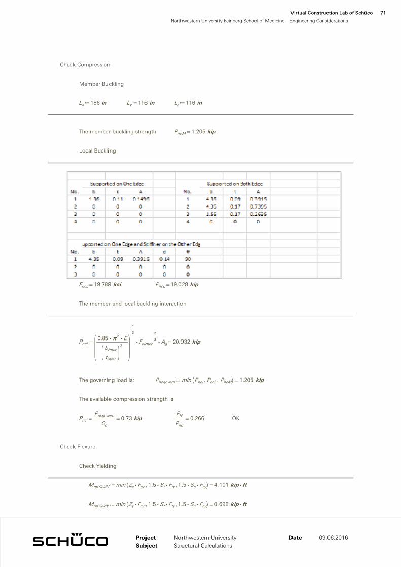
Member Buckling
≔Lx 186 in ≔Ly 116 in ≔Lz 116 in
The member buckling strength =PncM 1.205 kip
Local Buckling
=FncL 19.789 ksi =PncL 19.028 kip
The member and local buckling interaction
≔PncI =⋅⋅⎛⎜⎜⎜⎝
――――⋅⋅0.85 π2 E
⎛⎜⎜⎝――binter
tinter
⎞⎟⎟⎠
2
⎞⎟⎟⎟⎠
―13
FeInter
―23 Ag 20.932 kip
The governing load is: ≔Pncgovern =min ⎛⎝ ,,PncI PncL PncM⎞⎠ 1.205 kip
The available compression strength is
≔Pnc =―――Pncgovern
Ωc
0.73 kip =――P1
Pnc
−0.139 OK
Check Flexure
Check Yielding
≔MnpYieldX =min ⎛⎝ ,,⋅Zx Fcy ⋅⋅1.5 St Fty ⋅⋅1.5 Sc Fcy⎞⎠ 4.101 ⋅kip ft
≔MnpYieldY =min ⎛⎝ ,,⋅Zy Fcy ⋅⋅1.5 St Fty ⋅⋅1.5 Sc Fcy⎞⎠ 0.698 ⋅kip ft
Check Rupture
≔MnpRupX =⋅Zx ――Ftu
kt
3.562 ⋅kip ft ≔MnpRupY =⋅Zy ――Ftu
kt
0.606 ⋅kip ft
ProjectSubject
Date 09.06.2016
Virtual Construction Lab of Schüco
Northwestern University Feinberg School of Medicine – Engineering Considerations
67
Northwestern UniversityStructural Calculations

Check Local Buckling - Flexure
=Fb 45.91 ksi ≔Fc =FncL 19.789 ksi
≔Mnlbx =+⋅Fc ――Ifccf
⋅Fb ――Iwccw
60.523 ⋅kip ft
≔Mnlby =+⋅Fc ――Ifccf
⋅Fb ――Iwccw
5.767 ⋅kip ft
Check Lateral Torsional Buckling
X Axis (Strong Axis)
=MnmbX 3.027 ⋅kip ft
=k2 2.27
Y Axis (Weak Axis)
=MnmbY 0.661 ⋅kip ft
≔Mnx =min⎛⎜⎜⎝
,,,―――MnpYieldX
Ωfother
―――MnpRupX
Ωfrupture
―――MnmbX
Ωfother
―――Mnlbx
Ωfother
⎞⎟⎟⎠
1.827 ⋅kip ft =――M1x
Mnx
0.301
OK
≔Mny =min⎛⎜⎜⎝
,,,―――MnpYieldY
Ωfother
―――MnpRupY
Ωfrupture
―――MnmbY
Ωfother
―――Mnlby
Ωfother
⎞⎟⎟⎠
0.311 ⋅kip ft =――M1y
Mny
−0.257
ProjectSubject
Date 09.06.2016
Virtual Construction Lab of Schüco
Northwestern University Feinberg School of Medicine – Engineering Considerations
68
Northwestern UniversityStructural Calculations

Check Local Buckling - Flexure
=Fb 45.91 ksi ≔Fc =FncL 19.789 ksi
≔Mnlbx =+⋅Fc ――Ifccf
⋅Fb ――Iwccw
60.523 ⋅kip ft
≔Mnlby =+⋅Fc ――Ifccf
⋅Fb ――Iwccw
5.767 ⋅kip ft
Check Lateral Torsional Buckling
X Axis (Strong Axis)
=MnmbX 3.027 ⋅kip ft
=k2 2.27
Y Axis (Weak Axis)
=MnmbY 0.661 ⋅kip ft
≔Mnx =min⎛⎜⎜⎝
,,,―――MnpYieldX
Ωfother
―――MnpRupX
Ωfrupture
―――MnmbX
Ωfother
―――Mnlbx
Ωfother
⎞⎟⎟⎠
1.827 ⋅kip ft =――M1x
Mnx
0.301
OK
≔Mny =min⎛⎜⎜⎝
,,,―――MnpYieldY
Ωfother
―――MnpRupY
Ωfrupture
―――MnmbY
Ωfother
―――Mnlby
Ωfother
⎞⎟⎟⎠
0.311 ⋅kip ft =――M1y
Mny
−0.257
Check Shear
Check the Y direction Shear
≔Type 0 1 stands for the support on both edges, while 0 stands for the support on one edge.
≔bs 1.5 in ≔ts 0.17 in ≔ds 8.0625 in
The available shear strength is
≔VY =min⎛⎜⎜⎝
,―――Vnrup
Ωsrupture
―――Vnyield
Ωsother
⎞⎟⎟⎠
3.245 kip =――V1y
VY
0.042 OK
Check the X direction Shear
≔Type 0 1 stands for the support on both edges, while 0 stands for the support on one edge.
≔bs 1 in ≔ts 0.125 in ≔ds 1.75 in
The available shear strength is
≔VX =min⎛⎜⎜⎝
,―――Vnrup
Ωsrupture
―――Vnyield
Ωsother
⎞⎟⎟⎠
1.591 kip =――V1x
VX
0.114 OK
Check Torque
≔t 0.125 in
≔C =―Jt
5.773 in3 ≔Tnrupture =⋅――Fsu
kt
C 8.775 ⋅kip ft ≔Tnyield =⋅Fnyield C 10.102 ⋅kip ft
≔Tn =min⎛⎜⎜⎝
,―――Tnrupture
Ωtorrupture
―――Tnyield
Ωtorother
⎞⎟⎟⎠
4.5 ⋅kip ft
≔Safety =―T1
Tn
0.193
Check the Combination of Loads
=+++++――P1
Pnc
⎛⎜⎜⎝――M1x
Mnx
⎞⎟⎟⎠
2 ⎛⎜⎜⎝――M1y
Mny
⎞⎟⎟⎠
2 ⎛⎜⎜⎝――V1x
VX
⎞⎟⎟⎠
2 ⎛⎜⎜⎝――V1y
VY
⎞⎟⎟⎠
2 ⎛⎜⎜⎝―T1
Tn
⎞⎟⎟⎠
2
0.07 OK
ProjectSubject
Date 09.06.2016
Virtual Construction Lab of Schüco
Northwestern University Feinberg School of Medicine – Engineering Considerations
69
Northwestern UniversityStructural Calculations

S9 The Vertical Mullions Check
Section Properties
≔As =S (( ,5 1)) in2 0.969 in2 ≔ws =⋅As 170 pcf 1.144 ――lbf
ft
≔d =S (( ,1 1)) in 8.071 in
≔Ixx =S (( ,6 1)) in4 6.494 in4 ≔rxx =‾‾‾――Ixx
As
2.589 in
≔Iyy =S (( ,7 1)) in4 0.191 in4 ≔ryy =‾‾‾――Iyy
As
0.444 in
≔Sxp =S (( ,11 1)) in3 1.55 in3 ≔Sxn =S (( ,12 1)) in3 1.673 in3
≔Syp =S (( ,13 1)) in3 0.192 in3 ≔Syn =S (( ,14 1)) in3 0.381 in3
≔J =S (( ,48 1)) in4 0.722 in4 ≔Cw =S (( ,47 1)) in6 4.004 in6
≔xs =S (( ,45 1)) in −0.517 in ≔ys =S (( ,46 1)) in −0.344 in
≔Zx =S (( ,31 1)) in3 1.406 in3 ≔Zy =S (( ,32 1)) in3 0.239 in3
≔βx =⋅S (( ,49 1)) in 1.031 in
Member Forces
ProjectSubject
Date 09.06.2016
Virtual Construction Lab of Schüco
Northwestern University Feinberg School of Medicine – Engineering Considerations
70
Northwestern UniversityStructural Calculations
S9 The Vertical Mullions Check
Section Properties
≔As =S (( ,5 1)) in2 0.969 in2 ≔ws =⋅As 170 pcf 1.144 ――lbf
ft
≔d =S (( ,1 1)) in 8.071 in
≔Ixx =S (( ,6 1)) in4 6.494 in4 ≔rxx =‾‾‾――Ixx
As
2.589 in
≔Iyy =S (( ,7 1)) in4 0.191 in4 ≔ryy =‾‾‾――Iyy
As
0.444 in
≔Sxp =S (( ,11 1)) in3 1.55 in3 ≔Sxn =S (( ,12 1)) in3 1.673 in3
≔Syp =S (( ,13 1)) in3 0.192 in3 ≔Syn =S (( ,14 1)) in3 0.381 in3
≔J =S (( ,48 1)) in4 0.722 in4 ≔Cw =S (( ,47 1)) in6 4.004 in6
≔xs =S (( ,45 1)) in −0.517 in ≔ys =S (( ,46 1)) in −0.344 in
≔Zx =S (( ,31 1)) in3 1.406 in3 ≔Zy =S (( ,32 1)) in3 0.239 in3
≔βx =⋅S (( ,49 1)) in 1.031 in
Member Forces
Check Compression
Member Buckling
≔Lx 186 in ≔Ly 116 in ≔Lz 116 in
The member buckling strength =PncM 1.205 kip
Local Buckling
=FncL 19.789 ksi =PncL 19.028 kip
The member and local buckling interaction
≔PncI =⋅⋅⎛⎜⎜⎜⎝
――――⋅⋅0.85 π2 E
⎛⎜⎜⎝――binter
tinter
⎞⎟⎟⎠
2
⎞⎟⎟⎟⎠
―13
FeInter
―23 Ag 20.932 kip
The governing load is: ≔Pncgovern =min ⎛⎝ ,,PncI PncL PncM⎞⎠ 1.205 kip
The available compression strength is
≔Pnc =―――Pncgovern
Ωc
0.73 kip =――P9
Pnc
0.266 OK
Check Flexure
Check Yielding
≔MnpYieldX =min ⎛⎝ ,,⋅Zx Fcy ⋅⋅1.5 St Fty ⋅⋅1.5 Sc Fcy⎞⎠ 4.101 ⋅kip ft
≔MnpYieldY =min ⎛⎝ ,,⋅Zy Fcy ⋅⋅1.5 St Fty ⋅⋅1.5 Sc Fcy⎞⎠ 0.698 ⋅kip ft
ProjectSubject
Date 09.06.2016
Virtual Construction Lab of Schüco
Northwestern University Feinberg School of Medicine – Engineering Considerations
71
Northwestern UniversityStructural Calculations

Check Rupture
≔MnpRupX =⋅Zx ――Ftu
kt
3.562 ⋅kip ft ≔MnpRupY =⋅Zy ――Ftu
kt
0.606 ⋅kip ft
Check Local Buckling - Flexure
=Fb 45.91 ksi ≔Fc =FncL 19.789 ksi
≔Mnlbx =+⋅Fc ――Ifccf
⋅Fb ――Iwccw
60.523 ⋅kip ft
≔Mnlby =+⋅Fc ――Ifccf
⋅Fb ――Iwccw
5.767 ⋅kip ft
Check Lateral Torsional Buckling
X Axis (Strong Axis)
=MnmbX 3.027 ⋅kip ft
Y Axis (Weak Axis)
=MnmbY 0.661 ⋅kip ft
≔Mnx =min⎛⎜⎜⎝
,,,―――MnpYieldX
Ωfother
―――MnpRupX
Ωfrupture
―――MnmbX
Ωfother
―――Mnlbx
Ωfother
⎞⎟⎟⎠
1.827 ⋅kip ft =――M9
Mnx
0.772 OK
≔Mny =min⎛⎜⎜⎝
,,,―――MnpYieldY
Ωfother
―――MnpRupY
Ωfrupture
―――MnmbY
Ωfother
―――Mnlby
Ωfother
⎞⎟⎟⎠
0.311 ⋅kip ft
ProjectSubject
Date 09.06.2016
Virtual Construction Lab of Schüco
Northwestern University Feinberg School of Medicine – Engineering Considerations
72
Northwestern UniversityStructural Calculations

Check Rupture
≔MnpRupX =⋅Zx ――Ftu
kt
3.562 ⋅kip ft ≔MnpRupY =⋅Zy ――Ftu
kt
0.606 ⋅kip ft
Check Local Buckling - Flexure
=Fb 45.91 ksi ≔Fc =FncL 19.789 ksi
≔Mnlbx =+⋅Fc ――Ifccf
⋅Fb ――Iwccw
60.523 ⋅kip ft
≔Mnlby =+⋅Fc ――Ifccf
⋅Fb ――Iwccw
5.767 ⋅kip ft
Check Lateral Torsional Buckling
X Axis (Strong Axis)
=MnmbX 3.027 ⋅kip ft
Y Axis (Weak Axis)
=MnmbY 0.661 ⋅kip ft
≔Mnx =min⎛⎜⎜⎝
,,,―――MnpYieldX
Ωfother
―――MnpRupX
Ωfrupture
―――MnmbX
Ωfother
―――Mnlbx
Ωfother
⎞⎟⎟⎠
1.827 ⋅kip ft =――M9
Mnx
0.772 OK
≔Mny =min⎛⎜⎜⎝
,,,―――MnpYieldY
Ωfother
―――MnpRupY
Ωfrupture
―――MnmbY
Ωfother
―――Mnlby
Ωfother
⎞⎟⎟⎠
0.311 ⋅kip ft
Check Shear
Check the shear in Y-axis
≔Type 0 1 stands for the support on both edges, while 0 stands for the support on one edge.
≔bs 1.5 in ≔ts 0.17 in ≔ds 8.0625 in
The available shear strength is
≔VY =min⎛⎜⎜⎝
,―――Vnrup
Ωsrupture
―――Vnyield
Ωsother
⎞⎟⎟⎠
3.245 kip =――V9Y
VY
0.156
Check the shear in X-axis
≔Type 0 1 stands for the support on both edges, while 0 stands for the support on one edge.
≔bs 1 in ≔ts 0.125 in ≔ds 1.5 in
The available shear strength is
≔VX =min⎛⎜⎜⎝
,―――Vnrup
Ωsrupture
―――Vnyield
Ωsother
⎞⎟⎟⎠
1.591 kip =――V9X
VX
0.064
Check the Combination of Loads
=+++――P9
Pnc
⎛⎜⎜⎝――M9
Mnx
⎞⎟⎟⎠
2 ⎛⎜⎜⎝――V9X
VX
⎞⎟⎟⎠
2 ⎛⎜⎜⎝――V9Y
VY
⎞⎟⎟⎠
2
0.89 OK
ProjectSubject
Date 09.06.2016
Virtual Construction Lab of Schüco
Northwestern University Feinberg School of Medicine – Engineering Considerations
73
Northwestern UniversityStructural Calculations

S10 The Lower Transom Check
Section Properties
≔As =S (( ,5 1)) in2 2.585 in2
≔ws =⋅As 170 pcf 3.052 ――lbf
ft
≔d =S (( ,1 1)) in 3.228 in
≔Ixx =S (( ,6 1)) in4 5.184 in4
≔Iyy =S (( ,7 1)) in4 20.16 in4
≔rxx =‾‾‾――Ixx
As
1.416 in ≔ryy =‾‾‾――Iyy
As
2.793 in
≔Sxp =S (( ,11 1)) in3 3.211 in3 ≔Sxn =S (( ,12 1)) in3 3.211 in3
≔Syp =S (( ,13 1)) in3 5.32 in3 ≔Syn =S (( ,14 1)) in3 4.752 in3
≔J =S (( ,48 1)) in4 12.63 in4 ≔Cw =S (( ,47 1)) in6 3.99 in6
≔xs =S (( ,45 1)) in ⎛⎝ ⋅2.51 103 ⎞⎠ in ≔ys =S (( ,46 1)) in ⎛⎝ ⋅1.378 103 ⎞⎠ in
≔Zx =S (( ,31 1)) in3 3.507 in3 ≔Zy =S (( ,32 1)) in3 6.381 in3
≔βx =⋅S (( ,49 1)) in −1.177 in
Member Forces
Check Compression
Member Buckling
≔Lx 35 in ≔Ly 35 in ≔Lz 35 in
The member buckling strength =PncM 84.185 kip
ProjectSubject
Date 09.06.2016
Virtual Construction Lab of Schüco
Northwestern University Feinberg School of Medicine – Engineering Considerations
74
Northwestern UniversityStructural Calculations

S10 The Lower Transom Check
Section Properties
≔As =S (( ,5 1)) in2 2.585 in2
≔ws =⋅As 170 pcf 3.052 ――lbf
ft
≔d =S (( ,1 1)) in 3.228 in
≔Ixx =S (( ,6 1)) in4 5.184 in4
≔Iyy =S (( ,7 1)) in4 20.16 in4
≔rxx =‾‾‾――Ixx
As
1.416 in ≔ryy =‾‾‾――Iyy
As
2.793 in
≔Sxp =S (( ,11 1)) in3 3.211 in3 ≔Sxn =S (( ,12 1)) in3 3.211 in3
≔Syp =S (( ,13 1)) in3 5.32 in3 ≔Syn =S (( ,14 1)) in3 4.752 in3
≔J =S (( ,48 1)) in4 12.63 in4 ≔Cw =S (( ,47 1)) in6 3.99 in6
≔xs =S (( ,45 1)) in ⎛⎝ ⋅2.51 103 ⎞⎠ in ≔ys =S (( ,46 1)) in ⎛⎝ ⋅1.378 103 ⎞⎠ in
≔Zx =S (( ,31 1)) in3 3.507 in3 ≔Zy =S (( ,32 1)) in3 6.381 in3
≔βx =⋅S (( ,49 1)) in −1.177 in
Member Forces
Check Compression
Member Buckling
≔Lx 35 in ≔Ly 35 in ≔Lz 35 in
The member buckling strength =PncM 84.185 kip
Local Buckling
=FncL 14.829 ksi =PncL 69.572 kip
The member and local buckling interaction
≔PncI =⋅⋅⎛⎜⎜⎜⎝
――――⋅⋅0.85 π2 E
⎛⎜⎜⎝――binter
tinter
⎞⎟⎟⎠
2
⎞⎟⎟⎟⎠
―13
FeInter
―23 Ag 31.353 kip
The governing load is: ≔Pncgovern =min ⎛⎝ ,,PncI PncL PncM⎞⎠ 31.353 kip
The available compression strength is
≔Pnc =―――Pncgovern
Ωc
19.002 kip
Check Flexure
Check Yielding
≔MnpYieldX =min ⎛⎝ ,,⋅Zx Fcy ⋅⋅1.5 St Fty ⋅⋅1.5 Sc Fcy⎞⎠ 10.229 ⋅kip ft
≔MnpYieldY =min ⎛⎝ ,,⋅Zy Fcy ⋅⋅1.5 St Fty ⋅⋅1.5 Sc Fcy⎞⎠ 14.048 ⋅kip ft
Check Rupture
≔MnpRupX =⋅Zx ――Ftu
kt
8.884 ⋅kip ft ≔MnpRupY =⋅Zy ――Ftu
kt
16.165 ⋅kip ft
ProjectSubject
Date 09.06.2016
Virtual Construction Lab of Schüco
Northwestern University Feinberg School of Medicine – Engineering Considerations
75
Northwestern UniversityStructural Calculations

Check Local Buckling - Flexure
=Fb 44.482 ksi ≔Fc =FncL 14.829 ksi
≔Mnlbx =+⋅Fc ――Ifccf
⋅Fb ――Iwccw
11.054 ⋅kip ft
≔Mnlby =+⋅Fc ――Ifccf
⋅Fb ――Iwccw
10.76 ⋅kip ft
Check Lateral Torsional Buckling
X Axis (Strong Axis)
=MnmbX 9.879 ⋅kip ft
Y Axis (Weak Axis)
=MnmbY 13.305 ⋅kip ft
≔Mnx =min⎛⎜⎜⎝
,,,―――MnpYieldX
Ωfother
―――MnpRupX
Ωfrupture
―――MnmbX
Ωfother
―――Mnlbx
Ωfother
⎞⎟⎟⎠
4.556 ⋅kip ft
≔Mny =min⎛⎜⎜⎝
,,,―――MnpYieldY
Ωfother
―――MnpRupY
Ωfrupture
―――MnmbY
Ωfother
―――Mnlby
Ωfother
⎞⎟⎟⎠
6.521 ⋅kip ft
=――M101
Mny
0.109 =――M103
Mny
0.077 OK
ProjectSubject
Date 09.06.2016
Virtual Construction Lab of Schüco
Northwestern University Feinberg School of Medicine – Engineering Considerations
76
Northwestern UniversityStructural Calculations

Check Local Buckling - Flexure
=Fb 44.482 ksi ≔Fc =FncL 14.829 ksi
≔Mnlbx =+⋅Fc ――Ifccf
⋅Fb ――Iwccw
11.054 ⋅kip ft
≔Mnlby =+⋅Fc ――Ifccf
⋅Fb ――Iwccw
10.76 ⋅kip ft
Check Lateral Torsional Buckling
X Axis (Strong Axis)
=MnmbX 9.879 ⋅kip ft
Y Axis (Weak Axis)
=MnmbY 13.305 ⋅kip ft
≔Mnx =min⎛⎜⎜⎝
,,,―――MnpYieldX
Ωfother
―――MnpRupX
Ωfrupture
―――MnmbX
Ωfother
―――Mnlbx
Ωfother
⎞⎟⎟⎠
4.556 ⋅kip ft
≔Mny =min⎛⎜⎜⎝
,,,―――MnpYieldY
Ωfother
―――MnpRupY
Ωfrupture
―――MnmbY
Ωfother
―――Mnlby
Ωfother
⎞⎟⎟⎠
6.521 ⋅kip ft
=――M101
Mny
0.109 =――M103
Mny
0.077 OK
Check Shear
Check Shear in X direction
≔Type 0 1 stands for the support on both edges, while 0 stands for the support on one edge.
≔bs 3 in ≔ts 0.125 in ≔ds 8.0625 in
The available shear strength is
≔VX =⋅2 min⎛⎜⎜⎝
,―――Vnrup
Ωsrupture
―――Vnyield
Ωsother
⎞⎟⎟⎠
7.752 kip =――V101X
VX
−0.022 =――V103X
VX
−0.026
Check Shear in Y direction
≔Type 0 1 stands for the support on both edges, while 0 stands for the support on one edge.
≔bs 8.0625 in ≔ts 0.125 in ≔ds 3 in
The available shear strength is
≔VX =⋅2 min⎛⎜⎜⎝
,―――Vnrup
Ωsrupture
―――Vnyield
Ωsother
⎞⎟⎟⎠
3.252 kip =――V101Y
VX
0.019 =――V103Y
VX
0.019
Check the Combination of Loads
=++⎛⎜⎜⎝――M101
Mny
⎞⎟⎟⎠
2 ⎛⎜⎜⎝――V101X
VX
⎞⎟⎟⎠
2 ⎛⎜⎜⎝――V101Y
VY
⎞⎟⎟⎠
2
0.015 OK
=++⎛⎜⎜⎝――M103
Mny
⎞⎟⎟⎠
2 ⎛⎜⎜⎝――V103X
VX
⎞⎟⎟⎠
2 ⎛⎜⎜⎝――V103Y
VY
⎞⎟⎟⎠
2
0.01 OK
ProjectSubject
Date 09.06.2016
Virtual Construction Lab of Schüco
Northwestern University Feinberg School of Medicine – Engineering Considerations
77
Northwestern UniversityStructural Calculations

S11 Anchor Design
Anchor Loads (From Reactions)
≔Px =2 ((578.84 lbf)) 1.158 kip
≔Py =⋅2 ((319.27 lbf)) 0.639 kip
≔Pyml =1500 lbf 1.5 kip
Material
Aluminum Extusions (6061-T5 or 6005A-T61)
≔Fbr =31 ksi 214 MPa ≔Fs =12 ksi 82.737 MPa
≔Fb =28 ksi 193.053 MPa ≔Ft =19 ksi 131 MPa
Minimum Wall Thickness ≔tm =0.125 in 3.175 mm
Bolts (Steel A325 or M5)
Diameter ≔db =.625 in 16 mm
Shear Capacity ≔Vbs =3.58 kip 15.925 kN
Bearing Capacity ≔Vbb =⋅⋅Fbr db tm 2.422 kip =Vbb 10.773 kN
Generric Anchor-Bolt Pattern May Varry
ProjectSubject
Date 09.06.2016
Virtual Construction Lab of Schüco
Northwestern University Feinberg School of Medicine – Engineering Considerations
78
Northwestern UniversityStructural Calculations

S11 Anchor Design
Anchor Loads (From Reactions)
≔Px =2 ((578.84 lbf)) 1.158 kip
≔Py =⋅2 ((319.27 lbf)) 0.639 kip
≔Pyml =1500 lbf 1.5 kip
Material
Aluminum Extusions (6061-T5 or 6005A-T61)
≔Fbr =31 ksi 214 MPa ≔Fs =12 ksi 82.737 MPa
≔Fb =28 ksi 193.053 MPa ≔Ft =19 ksi 131 MPa
Minimum Wall Thickness ≔tm =0.125 in 3.175 mm
Bolts (Steel A325 or M5)
Diameter ≔db =.625 in 16 mm
Shear Capacity ≔Vbs =3.58 kip 15.925 kN
Bearing Capacity ≔Vbb =⋅⋅Fbr db tm 2.422 kip =Vbb 10.773 kN
Generric Anchor-Bolt Pattern May Varry
Check the Anchor Bolt
Number of Bolts ≔N 4
Number of Row ≔Row 2
Eccentricities ≔Gx 2.825 in
≔Gy .625 in
Tolerance ≔Tx 1.5 in
≔Ty 2.0 in
Coordinates ≔Bx 2.0 in
≔By 2.0 in
≔x
00−Bx
−Bx
⎡⎢⎢⎢⎢⎣
⎤⎥⎥⎥⎥⎦
≔y
0By
By
0
⎡⎢⎢⎢⎢⎣
⎤⎥⎥⎥⎥⎦
Group Centroid ≔xc =――∑ x
N−1 in
≔yc =――∑ y
N1 in
Applied Moment at Centroid of Bolts
≔Mdl.wl =+⋅Py⎛⎝ +−Gx xc Tx
⎞⎠ ⋅Px⎛⎝ ++Gy yc Ty
⎞⎠ 7.597 ⋅kip in
≔Mdl.ml =⋅⎛⎝ +Py Pyml⎞⎠ ⎛⎝ +−Gx xc Tx
⎞⎠ 11.388 ⋅kip in ≔Mdl =max ⎛⎝ ,Mdl.ml Mdl.wl⎞⎠ 11.388 ⋅kip in
Torsion Constant:
≔J =+∑⎛⎝ −y yc⎞⎠
2
∑⎛⎝ −x xc⎞⎠
2
8 in2
Resultant Shear Force at Each Fasterner:
≔V =
‾‾‾‾‾‾‾‾‾‾‾‾‾‾‾‾‾‾‾‾‾‾‾‾‾‾‾‾‾‾‾‾‾‾‾‾‾‾‾‾‾‾‾‾‾‾‾‾‾‾‾‾‾‾‾‾‾‾
+⎛⎜⎜⎜⎝
+―Px
N―――――――――⋅Mdl
‾‾‾‾‾‾‾‾‾‾‾‾‾‾‾‾+⎛⎝ −y yc
⎞⎠2 ⎛⎝ −x xc
⎞⎠2
⋅J ‾‾2
⎞⎟⎟⎟⎠
2 ⎛⎜⎜⎜⎝
+―Py
N―――――――――⋅Mdl
‾‾‾‾‾‾‾‾‾‾‾‾‾‾‾‾+⎛⎝ −y yc
⎞⎠2 ⎛⎝ −x xc
⎞⎠2
⋅J ‾‾2
⎞⎟⎟⎟⎠
22.32.32.32.3
⎡⎢⎢⎢⎣
⎤⎥⎥⎥⎦
kip
≔Vmax =max ((V)) 2.332 kip
=―――――Vmax
min ⎛⎝ ,Vbs Vbb⎞⎠
0.963 < 1.0 OK
ProjectSubject
Date 09.06.2016
Virtual Construction Lab of Schüco
Northwestern University Feinberg School of Medicine – Engineering Considerations
79
Northwestern UniversityStructural Calculations

Check Anchor Hook
≔da =―34
in 19 mm ≔h =1.5 in 38.1 mm
≔th =.625 in 15.875 mm ≔aa =⋅.675 in 17.145 mm
Location A
Shear ≔fv =――Px
⋅th aa
2.744 ksi < =Fs 12 ksi OK
Tension ≔ft =――Py
⋅th aa
1.514 ksi < =Ft 19 ksi OK
Bending ≔fb =⋅―――⋅Px
⎛⎜⎝―da
2
⎞⎟⎠
⋅th aa2
6 9.147 ksi < =Ft 19 ksi OK
Combined =+⎛⎜⎜⎝―fb
Fb
⎞⎟⎟⎠
2 ⎛⎜⎜⎝―fv
Fs
⎞⎟⎟⎠
2
0.159 < 1.0 OK
Point B
Shear ≔fv =――Py
⋅th h0.681 ksi < =Fs 12 ksi OK
Tension ≔ft =――Px
⋅th h1.235 ksi < =Ft 19 ksi OK
Bending ≔fb =⋅―――――⋅Px
⎛⎜⎝
+―h2
―da
2
⎞⎟⎠
⋅th h26 5.6 < =Ft 19 ksi OK
Combined =+⎛⎜⎜⎝―fb
Fb
⎞⎟⎟⎠
2 ⎛⎜⎜⎝―fv
Fs
⎞⎟⎟⎠
2
0.043 < 1.0 OK
=+―ft
Ft
―fb
Fb
0.263 < 1.0 OK
Miantenance Load
Shear ≔fv =―――+Py Pyml
⋅th h2.281 ksi < =Fs 12 ksi OK
ProjectSubject
Date 09.06.2016
Virtual Construction Lab of Schüco
Northwestern University Feinberg School of Medicine – Engineering Considerations
80
Northwestern UniversityStructural Calculations

Check Anchor Hook
≔da =―34
in 19 mm ≔h =1.5 in 38.1 mm
≔th =.625 in 15.875 mm ≔aa =⋅.675 in 17.145 mm
Location A
Shear ≔fv =――Px
⋅th aa
2.744 ksi < =Fs 12 ksi OK
Tension ≔ft =――Py
⋅th aa
1.514 ksi < =Ft 19 ksi OK
Bending ≔fb =⋅―――⋅Px
⎛⎜⎝―da
2
⎞⎟⎠
⋅th aa2
6 9.147 ksi < =Ft 19 ksi OK
Combined =+⎛⎜⎜⎝―fb
Fb
⎞⎟⎟⎠
2 ⎛⎜⎜⎝―fv
Fs
⎞⎟⎟⎠
2
0.159 < 1.0 OK
Point B
Shear ≔fv =――Py
⋅th h0.681 ksi < =Fs 12 ksi OK
Tension ≔ft =――Px
⋅th h1.235 ksi < =Ft 19 ksi OK
Bending ≔fb =⋅―――――⋅Px
⎛⎜⎝
+―h2
―da
2
⎞⎟⎠
⋅th h26 5.6 < =Ft 19 ksi OK
Combined =+⎛⎜⎜⎝―fb
Fb
⎞⎟⎟⎠
2 ⎛⎜⎜⎝―fv
Fs
⎞⎟⎟⎠
2
0.043 < 1.0 OK
=+―ft
Ft
―fb
Fb
0.263 < 1.0 OK
Miantenance Load
Shear ≔fv =―――+Py Pyml
⋅th h2.281 ksi < =Fs 12 ksi OK
Check Anchor
≔wa =10 in 254 mm ≔ta =0.5 in 12.7 mm
≔dx =1.625 in 41.3 mm ≔dy =1.375 in 34.9 mm ≔TOLx =2 in 50.8 mm
Shear ≔fv =―――Py
⋅ta wa
0.1 ksi < =Fs 12 ksi OK
Bending ≔fb =⋅―――――――――+⋅Px dy ⋅Py⎛⎝ +dx TOLx
⎞⎠⋅⎛⎝ −wa ⋅2 ((1.0625 in))⎞⎠ ta
26 11.9 ksi < =Fb 28 ksi OK
< 1.0 OK
Combined =+⎛⎜⎜⎝―fb
Fb
⎞⎟⎟⎠
2 ⎛⎜⎜⎝―fv
Fs
⎞⎟⎟⎠
2
0.2
Miantenance Load
Shear ≔fv =―――+Py Pyml
⋅ta wa
0.4 ksi < =Fs 12 ksi OK
Bending ≔fb =⋅―――――――――⋅⎛⎝ +Py Pyml⎞⎠ ⎛⎝ +dx TOLx
⎞⎠⋅⎛⎝ −wa ⋅2 ((1.0625 in))⎞⎠ ta
26 23.6 ksi < =Fb 28 ksi OK
High-Tensile T-Bolts ≔TOLz =1 in 25.4 mm ≔TOLx =1 in 25.4 mm ≔TOLy =1 in 25.4 mm
≔dTb =0.81 in 20.574 mm ≔bo =6.5 in 165.1 mm
Allowable Loads ≔Vall 3.45 kip ≔Tall 5.2 kip
≔vTb =Px 1.158 kip
≔tTb =――――――――――+⋅Px dy ⋅Py⎛⎝ ++dx TOLx 0.1 bo
⎞⎠bo
0.567 kip
=+⎛⎜⎜⎝――vTb
Vall
⎞⎟⎟⎠
2 ⎛⎜⎜⎝――tTb
Tall
⎞⎟⎟⎠
2
0.124 < 1.0 OK
Miantenance Load
≔tTb =―――――――――――⋅⎛⎝ +Py Pyml⎞⎠ ⎛⎝ ++dx TOLx ⋅0.1 bo
⎞⎠⋅0.9 bo
1.2 kip < =Tall 5.2 kip OK
ProjectSubject
Date 09.06.2016
Virtual Construction Lab of Schüco
Northwestern University Feinberg School of Medicine – Engineering Considerations
81
Northwestern UniversityStructural Calculations
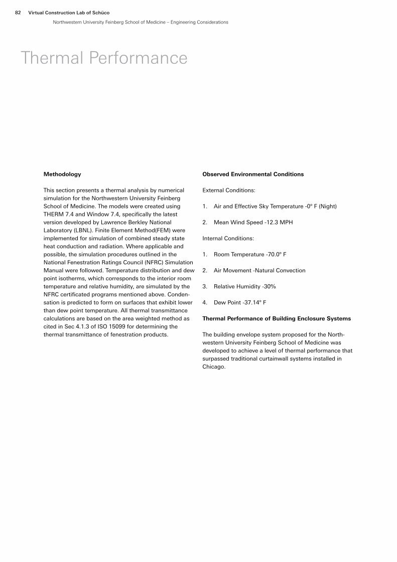
Methodology
This section presents a thermal analysis by numerical simulation for the Northwestern University Feinberg School of Medicine. The models were created using THERM 7.4 and Window 7.4, specifically the latest version developed by Lawrence Berkley National Laboratory (LBNL). Finite Element Method(FEM) were implemented for simulation of combined steady state heat conduction and radiation. Where applicable and possible, the simulation procedures outlined in the National Fenestration Ratings Council (NFRC) Simulation Manual were followed. Temperature distribution and dew point isotherms, which corresponds to the interior room temperature and relative humidity, are simulated by the NFRC certificated programs mentioned above. Conden-sation is predicted to form on surfaces that exhibit lower than dew point temperature. All thermal transmittance calculations are based on the area weighted method as cited in Sec 4.1.3 of ISO 15099 for determining the thermal transmittance of fenestration products.
Observed Environmental Conditions
External Conditions:
1. Air and Effective Sky Temperature -0º F (Night)
2. Mean Wind Speed -12.3 MPH
Internal Conditions:
1. Room Temperature -70.0º F
2. Air Movement -Natural Convection
3. Relative Humidity -30%
4. Dew Point -37.14º F
Thermal Performance of Building Enclosure Systems
The building envelope system proposed for the North-western University Feinberg School of Medicine was developed to achieve a level of thermal performance that surpassed traditional curtainwall systems installed in Chicago.
Thermal Performance
Virtual Construction Lab of Schüco
Northwestern University Feinberg School of Medicine – Engineering Considerations
82

Project Northwestern Date <08.19.2016>
Subject Thermal Calculations Plate 3
D3 Color Contour Diagram of Material
Material Properties
Material λ (W/Mk)
EPDM 0.250
Aluminum (Painted) Ɛ = 0.9 160.000
Aluminum Alloy (mill finish) Ɛ = 0.05 160.000
Mineral Fiber - Low Density Ɛ = 0.9 0.042
Silicone Ɛ = 0.9 0.350
Polyvinylchloride(PVC)/Vinyl-Rigid Ɛ = 0.9 0.170
Polyurethane foam Ɛ = 0.9 0.0289
Project Northwestern Date <08.19.2016>
Subject Thermal Calculations Plate 2
D1 Color Contour Diagram of Material
Project Northwestern Date <08.19.2016>
Subject Thermal Calculations Plate 3
D3 Color Contour Diagram of Material
Material Properties
Material λ (W/Mk)
EPDM 0.250
Aluminum (Painted) Ɛ = 0.9 160.000
Aluminum Alloy (mill finish) Ɛ = 0.05 160.000
Mineral Fiber - Low Density Ɛ = 0.9 0.042
Silicone Ɛ = 0.9 0.350
Polyvinylchloride(PVC)/Vinyl-Rigid Ɛ = 0.9 0.170
Polyurethane foam Ɛ = 0.9 0.0289
D1
Color Contour Diagram of Material
D3
Color Contour Diagram of Material
ProjectSubject
Date 09.06.2016
Virtual Construction Lab of Schüco
Northwestern University Feinberg School of Medicine – Engineering Considerations
83
Northwestern UniversityThermal Calculations

Project Northwestern Date <08.19.2016>
Subject Thermal Calculations Plate 4
D1
Color Contour Diagram of Temperature
D1
Isothermal Line of Dew Point Temperature
ProjectSubject
Date 09.06.2016
Virtual Construction Lab of Schüco
Northwestern University Feinberg School of Medicine – Engineering Considerations
84
Northwestern UniversityThermal Calculations

Project Northwestern Date <08.19.2016>
Subject Thermal Calculations Plate 5
D2
Color Contour Diagram of Temperature
D2
Isothermal Line of Dew Point Temperature
ProjectSubject
Date 09.06.2016
Virtual Construction Lab of Schüco
Northwestern University Feinberg School of Medicine – Engineering Considerations
85
Northwestern UniversityThermal Calculations

Project Northwestern Date <08.19.2016>
Subject Thermal Calculations Plate 6
D3
Color Contour Diagram of Temperature
D3
Isothermal Line of Dew Point Temperature
ProjectSubject
Date 09.06.2016
Virtual Construction Lab of Schüco
Northwestern University Feinberg School of Medicine – Engineering Considerations
86
Northwestern UniversityThermal Calculations

Project Northwestern Date <08.19.2016>
Subject Thermal Calculations Plate 7
D11 Color Contour Diagram of Temperature
D11 Isothermal Line of Dew Point Temperature
ProjectSubject
Date 09.06.2016
Virtual Construction Lab of Schüco
Northwestern University Feinberg School of Medicine – Engineering Considerations
87
Northwestern UniversityThermal Calculations

Project Northwestern Date <08.19.2016>
Subject Thermal Calculations Plate 8
D12 Color Contour Diagram of Temperature
D12 Isothermal Line of Dew Point Temperature
ProjectSubject
Date 09.06.2016
Virtual Construction Lab of Schüco
Northwestern University Feinberg School of Medicine – Engineering Considerations
88
Northwestern UniversityThermal Calculations

Project Northwestern Date <08.19.2016>
Subject Thermal Calculations Plate 9
D13
D13 Color Contour Diagram of Temperature
D13 Isothermal Line of Dew Point Temperature
ProjectSubject
Date 09.06.2016
Virtual Construction Lab of Schüco
Northwestern University Feinberg School of Medicine – Engineering Considerations
89
Northwestern UniversityThermal Calculations

Project Northwestern Date <08.19.2016>
Subject Thermal Calculations Plate 10
D14 Color Contour Diagram of Temperature
D14 Isothermal Line of Dew Point Temperature
ProjectSubject
Date 09.06.2016
Virtual Construction Lab of Schüco
Northwestern University Feinberg School of Medicine – Engineering Considerations
90
Northwestern UniversityThermal Calculations

Project Northwestern Date <08.19.2016>
Subject Thermal Calculations Plate 11
D15 Color Contour Diagram of Temperature
D15 Isothermal Line of Dew Point Temperature
ProjectSubject
Date 09.06.2016
Virtual Construction Lab of Schüco
Northwestern University Feinberg School of Medicine – Engineering Considerations
91
Northwestern UniversityThermal Calculations

Project Northwestern Date <08.19.2016>
Subject Thermal Calculations Plate 12
D16 Color Contour Diagram of Temperature
D16 Isothermal Line of Dew Point Temperature
ProjectSubject
Date 09.06.2016
Virtual Construction Lab of Schüco
Northwestern University Feinberg School of Medicine – Engineering Considerations
92
Northwestern UniversityThermal Calculations

Project Northwestern Date <08.19.2016>
Subject Thermal Calculations Plate 13
System U-Factor Section of Elevation Evaluated
D1
D2
D1
D12 D14 D16
D13 D15
D13 D15
D11
D11
D3S1
VA1
VB1
S2
VA2
VB2
S3
VA3
VB3
660.0
1538.4
3077.6
4666.0
5.0° 5.0°6.0° 6.0° 6.0°
0.0° 0.0°
1260.0 1249.3 1270.2 1267.8 1252.6 1256.2
9988.7
D3
D2
D1
ProjectSubject
Date 09.06.2016
Virtual Construction Lab of Schüco
Northwestern University Feinberg School of Medicine – Engineering Considerations
93
Northwestern UniversityThermal Calculations

Project Northwestern Date <08.19.2016>
Subject Thermal Calculations Plate 14
Vision-A System Component Dimensions(IP)
Section V-1
Section V-2
Section V-3
Perimeter Dimensions [in] [in] [in]
Width 53.23 53.23 53.23
Height 38.50 38.50 38.50
Frame Dimensions [in] [in] [in]
Head 3.50 3.50 3.50
Right Jamb 3.63 3.63 3.63
Sill 3.50 3.50 3.50
Left Jamb 3.63 3.63 3.63
Edge of Glass Dimensions [in] [in] [in]
Head Edge 2.50 2.50 2.50
Right Jamb Edge 2.50 2.50 2.50
Sill Edge 2.50 2.50 2.50
Left Jamb Edge 2.50 2.50 2.50
Frame Areas [in2] [in2] [in2]
Head 173.62 173.62 173.62
Right Jamb 126.88 126.88 126.88
Sill 173.62 173.62 173.62
Left Jamb 126.88 126.88 126.88
Total Frame Areas 600.99 600.99 600.99
Edge of Glass Areas [in2] [in2] [in2]
Head Edge 108.70 108.70 108.70
Right Jamb Edge 72.50 72.50 72.50
Sill Edge 108.70 108.70 108.70
Left Jamb Edge 72.50 72.50 72.50
Total Edge Areas 362.40 362.40 362.40
Center of Glass Area [in2] [in2] [in2]
Center of Glass 1085.97 1085.97 1085.97
ProjectSubject
Date 09.06.2016
Virtual Construction Lab of Schüco
Northwestern University Feinberg School of Medicine – Engineering Considerations
94
Northwestern UniversityThermal Calculations

Project Northwestern Date <08.19.2016>
Subject Thermal Calculations Plate 15
Vision-A System Component U-Values(IP)
Section V-1
Section V-2
Section V-3
Frame U-Value [Btu/hr-sf-F] [Btu/hr-sf-F] [Btu/hr-sf-F]
Head 0.40 0.40 0.40
Right Jamb 0.79 0.79 0.80
Sill 0.89 0.89 0.89
Left Jamb 0.77 0.79 0.79
Edge of Glass U-Value [Btu/hr-sf-F] [Btu/hr-sf-F] [Btu/hr-sf-F]
Head 0.239 0.239 0.239
Right Jamb 0.234 0.234 0.234
Sill 0.231 0.231 0.231
Left Jamb 0.234 0.234 0.234
Center of Glass U-Value [Btu/hr-sf-F] [Btu/hr-sf-F] [Btu/hr-sf-F]
Center of Glass 0.23 0.23 0.23
Vision-A System Results per Section(IP)
Section
V-1 Section
V-2 Section
V-3
[Btu/hr-sf-F] [Btu/hr-sf-F] [Btu/hr-sf-F]
Frame U-Value 0.70 0.70 0.71
Edge U-Value 0.234 0.234 0.234
Center of Glass U-Value 0.23 0.23 0.23
Section U-Value 0.37 0.37 0.37
Overall Vision-A System Results(IP)
Total Frame Area 12.52 sf
Total Edge of Glass Area 7.55 sf
Total Center of Glass Area 22.62 sf
Total Area 42.69 sf
Overall Frame U-Value 0.70 [Btu/hr-sf-F]
Overall Edge of Glass U-Value 0.234 [Btu/hr-sf-F]
Overall Center of Glass U-Value 0.23 [Btu/hr-sf-F]
ProjectSubject
Date 09.06.2016
Virtual Construction Lab of Schüco
Northwestern University Feinberg School of Medicine – Engineering Considerations
95
Northwestern UniversityThermal Calculations

Project Northwestern Date <08.19.2016>
Subject Thermal Calculations Plate 16
Vision-B System Component Dimensions(IP)
Section
V-1 Section
V-2 Section
V-3
Perimeter Dimensions [in] [in] [in]
Width 53.23 53.23 53.23
Height 119.96 119.96 119.96
Frame Dimensions [in] [in] [in]
Head 3.50 3.50 3.50
Right Jamb 3.63 3.63 3.63
Sill 4.45 4.45 4.45
Left Jamb 3.63 3.63 3.63
Edge of Glass Dimensions
[in] [in] [in]
Head Edge 2.50 2.50 2.50
Right Jamb Edge 2.50 2.50 2.50
Sill Edge 2.50 2.50 2.50
Left Jamb Edge 2.50 2.50 2.50
Frame Areas [in2] [in2] [in2]
Head 173.62 173.62 173.62
Right Jamb 420.45 420.45 420.45
Sill 220.74 220.74 220.74
Left Jamb 420.45 420.45 420.45
Total Frame Areas 1235.25 1235.25 1235.25
Edge of Glass Areas [in2] [in2] [in2]
Head Edge 108.70 108.70 108.70
Right Jamb Edge 273.78 273.78 273.78
Sill Edge 108.70 108.70 108.70
Left Jamb Edge 273.78 273.78 273.78
Total Edge Areas 764.95 764.95 764.95
Center of Glass Area [in2] [in2] [in2]
Center of Glass 4385.27 4385.27 4385.27
ProjectSubject
Date 09.06.2016
Virtual Construction Lab of Schüco
Northwestern University Feinberg School of Medicine – Engineering Considerations
96
Northwestern UniversityThermal Calculations

Project Northwestern Date <08.19.2016>
Subject Thermal Calculations Plate 17
Vision-B System Component U-Values(IP)
Section
V-1 Section
V-2 Section
V-3
Frame U-Value [Btu/hr-sf-F] [Btu/hr-sf-F] [Btu/hr-sf-F]
Head 0.89 0.89 0.89
Right Jamb 0.79 0.79 0.80
Sill 0.43 0.43 0.43
Left Jamb 0.77 0.79 0.79
Edge of Glass U-Value [Btu/hr-sf-F] [Btu/hr-sf-F] [Btu/hr-sf-F]
Head 0.231 0.231 0.231
Right Jamb 0.234 0.234 0.234
Sill 0.232 0.232 0.232
Left Jamb 0.234 0.234 0.234
Center of Glass U-Value [Btu/hr-sf-F] [Btu/hr-sf-F] [Btu/hr-sf-F]
Center of Glass 0.23 0.23 0.23
Vision-B System Results per Section(IP)
Section
V-1 Section
V-2 Section
V-3
[Btu/hr-sf-F] [Btu/hr-sf-F] [Btu/hr-sf-F]
Frame U-Value 0.73 0.74 0.74
Edge U-Value 0.233 0.233 0.233
Center of Glass U-Value 0.23 0.23 0.23
Section U-Value 0.33 0.33 0.33
Overall Vision-B System Results(IP)
Total Frame Area
25.73 sf
Total Edge of Glass Area 15.94 sf
Total Center of Glass Area 91.36 sf
Total Area 133.03 sf
Overall Frame U-Value 0.74 [Btu/hr-sf-F]
Overall Edge of Glass U-Value 0.233 [Btu/hr-sf-F]
Overall Center of Glass U-Value 0.23 [Btu/hr-sf-F]
ProjectSubject
Date 09.06.2016
Virtual Construction Lab of Schüco
Northwestern University Feinberg School of Medicine – Engineering Considerations
97
Northwestern UniversityThermal Calculations

Project Northwestern Date <08.19.2016>
Subject Thermal Calculations Plate 18
Spandrel System Component Dimensions(IP)
Section
V-1 Section
V-2 Section
V-3
Perimeter Dimensions [in] [in] [in]
Width 53.23 53.23 53.23
Height 38.98 38.98 38.98
Frame Dimensions [in] [in] [in]
Head 4.45 4.45 4.45
Right Jamb 3.63 3.63 3.63
Sill 3.50 3.50 3.50
Left Jamb 3.63 3.63 3.63
Frame Areas [in2] [in2] [in2]
Head 220.74 220.74 220.74
Right Jamb 126.89 126.89 126.89
Sill 173.62 173.62 173.62
Left Jamb 126.89 126.89 126.89
Total Frame Areas 648.15 648.15 648.15
Insulation Infill Area [in2] [in2] [in2]
Center of Glass 1426.76 1426.76 1426.76
Spandrel System Component U-Values(IP)
Section
V-1 Section
V-2 Section
V-3
Frame U-Value [Btu/hr-sf-F] [Btu/hr-sf-F] [Btu/hr-sf-F]
Head 0.43 0.43 0.43
Right Jamb 0.29 0.29 0.29
Sill 0.40 0.40 0.40
Left Jamb 0.28 0.29 0.29
Infill R-Value [hr-sf-F/ Btu] [hr-sf-F/ Btu] [hr-sf-F/ Btu]
Infill U-Value 0.06 0.06 0.06
ProjectSubject
Date 09.06.2016
Virtual Construction Lab of Schüco
Northwestern University Feinberg School of Medicine – Engineering Considerations
98
Northwestern UniversityThermal Calculations

Project Northwestern Date <08.19.2016>
Subject Thermal Calculations Plate 19
Spandrel System Results per Section(IP)
Section
V-1 Section
V-2 Section
V-3
Section U-Value [Btu/hr-sf-F] [Btu/hr-sf-F] [Btu/hr-sf-F]
Frame U-Value 0.36 0.36 0.37
Infill U-Value 0.06 0.06 0.06
Section U-Value 0.15 0.15 0.16
Overall Spandrel System Results(IP)
Total Frame Area
13.50 sf
Total Infill Area 29.72 sf
Total Area 43.23 sf
Overall Frame U-Value 0.36 [Btu/hr-sf-F]
Overall Infill R- value 16.67 [Btu/hr-sf-F]
Overall System Results(IP)
Total Frame Area 51.76 sf
Total Infill Area 167.19 sf
Total Area 218.95 sf
Overall Frame U-Value 0.63 [Btu/hr-sf-F]
Overall Infill U-Value 0.20 [Btu/hr-sf-F]
System U-Value (IP)
Vision Areas 0.35 [Btu/hr-sf-F]
Spandrel Areas 0.15 [Btu/hr-sf-F]
Overall U-Value 0.31 [Btu/hr-sf-F]
ProjectSubject
Date 09.06.2016
Virtual Construction Lab of Schüco
Northwestern University Feinberg School of Medicine – Engineering Considerations
99
Northwestern UniversityThermal Calculations


Installation Methodology101

Installation Methodology
The system proposed here is designed to accommodate the glass fin unit installation methodology. All components will be manufac-tured to high tolerances to ensure a proper fit at the job site. The unit will come to site prefabri-cated in a protective bunk, with the fin attached separately from the tip table. This ensures no damage to the glass fin units during transporta-tion. The following sequence of activity is recommended, starting with hoisting the units to floor and ending with the installation of the saddle gaskets on set floors.
1. Hoist units. Using either tower crane or material hoist, the units will be brought to the installation floor. From there, they will be unwrapped and put onto a tip table.
2. Glass fin addition. From the tip table, the glass fin will be installed into the support brackets.
3. Installation at Floor Slab. Units will be installed at the slab edge from the floor above. Using the Jekko 265 Spider Crane, we recommend 4 total workers, two above and two on the installation floor.
4. Cover Caps. Once the units are set, the final cover cap will be installed onto the glass fin.
5. Saddle Gasket. The last step is to install the saddle gasket for the installed floor, spanning multiple units. Gasket shears will be used to notch the bottom, as well as cut the top flap. Glue and aluminum plates will be used at the gasket connections to secure them. A gasket roller will be used to finalize the unit installation.
Unloading units
Glass fin installed upright on unit
Fin wall installed at slab edge
Virtual Construction Lab of Schüco
Northwestern University Feinberg School of Medicine – Installation Methodology
102

Cover cap installed after next unit is placed
Saddle gasket installed
Virtual Construction Lab of Schüco
Northwestern University Feinberg School of Medicine – Installation Methodology
103


105Air & Water Infiltration

Air & Water Infiltration
Weathering performance of the curtainwall system is defined by an air and water primary line (plane) of demarcation between inside and out. Horizontally, this continuous barrier includes the exterior glass, its structural seal, the framing system, the framing internal seals, a horizontal primary gasket carried across unit joints and sealed at splices, and a silicone boot joining units and the primary gasket. Vertically, the barrier also includes glass, structural silicone, framing and seals, but the unit-to-unit seal is achieved through a vertical primary gasket sealed to the underside of the silicone boot and in contact with the primary horizontal seal gasket.
In the horizontal rainscreen, gaskets provide a first line of defense against water penetration by shielding the primary seal line and by creating a pressure equalized chamber in front of the primary seals.
This section diagrams the primary and secondary barrier lines of air and water infiltration for the key enclosure systems. Though only primary and secondary lines are shown, notice that a number of details have an additio-nal third line of defense against the elements.
The concept of the split-mullion unitized curtainwall system is a standard in the construction of mid and high-rise buildings. The process involves the fabrication of aluminum extrusions that are then assembled into frames and glazed with glass or other material (typically aluminum) panels under factory-controlled conditions. The units are then shipped to the site, hoisted into position, and hung off the building structure, where the split-mullions interlock to form a weather seal. In this section, the following weathering characteristics of the unitized curtainwall are discussed:
1. Water Penetration
2. Vapor Barrier Control
3. Condensation Control
4. Air Infiltration
Water Penetration
Water penetration through a barrier is the result of the single or combined effect of three factors; an opening through the barrier; capillary action on the wall surface; a pressure difference across the barrier as the result of wind. Eliminating any one of these factors can prevent water penetration. Curtainwalls need to move, therefore it is not possible to close all openings. It is also very difficult to keep curtainwalls dry at all times. Controlling the third factor—pressure differential—has proven to be the most practical strategy. The concept of the rain-screen was introduced in the early 20th century and was adopted by the curtainwall industry in the 1960s as a primary means of preventing water penetration. The concept, generally referred to as pressure equalized rainscreen (PER) is illustrated in Figure 1 above.
The PER concept is simple. If there is pressure equilibri-um between the outside and the air chambers of the extrusions (Po=Ps), any water penetrating the rain-screen will be drained through the chambers to the outside.
Stack Joint
The stack joint is the mating interface between upper and lower curtainwall units. It accommodates vertical movements imposed by structural live load deflections, temperature induced movements, and allowance for racking of the units during a seismic event. As a result the design of stack joint requires a high degree of articulation as well as the ability to maintain water and air seals. The concept of rainscreen is utilized in the design of the stack joint. A bulb gasket with positive con-tinuous contact is placed in between the sill engagement grove and the head attachment gusset to insure a reliable air and water barrier. The outermost line of defense (in this case tertiary) is provided by creation of a pressure-equalized chamber in front of this air barrier using an exterior wiper gasket (see Figure 2). The pressure inside this chamber is equalized to the pressure outside through openings at quarter-points on the wiper flaps. This system will eliminate the migration of moisture due to pressure differential between the exterior wall and rainscreen cavity. In addition, the tertiary barrier is designed to prevent the movement of
Virtual Construction Lab of Schüco
Northwestern University Feinberg School of Medicine – Air & Water Infiltration
106

Figure 1 - Pressure Equalized Rainscreen (PER)
Figure 2 - Glazing Pocket
Virtual Construction Lab of Schüco
Northwestern University Feinberg School of Medicine – Air & Water Infiltration
107

moisture due to capillary action, as well as providing protection against water penetration due to kinetic energy (driving rain) or other means of transport such as air stream or gravity.
Vertical Mullions
The diagram on page 110 represents the weathering system for the typical vertical split mullions. A two barrier system is also utilized here against water penetra-tion. The primary water/air barrier is located at the back of the mullion, running along the outside face of glass and bridging the joint along the field-applied wet-seal. This is once again the result of the unique interior seal condition. For the secondary vertical, continuous contact is established at the gasket between aluminum compo-nents.
Horizontal Mullions
Horizontal mullions are factory sealed and designed with two lines of protection; the primary line of defense is the silicone caulk line factory applied at the glass joint. The secondary line of defense is the metal extrusion, which is mechanically fastened to the vertical mullions. All the joinery connections are sealed using silicone joinery pads or factory applied silicone.
Glazing Pocket
Glazing pockets are drained to the outside using draina-ge holes on quarter-points of the horizontal span, or the corner points (see Figure 2).
Vapor Barrier Control
Vapor diffusion through an exterior wall is sometimes the cause of cavity wall wetness or condensation in winter. However, because unitized curtainwalls have compo-nents that are resistant to vapor diffusion (aluminum extrusions, glass, sheet metal panels, and gaskets), cavity moisture due to diffusion is not a concern.
Curtainwall Interface Details
As a standard practice, all interface conditions provided by Schüco systems employ redundancy through a strategy of primary and secondary protection barriers.
Virtual Construction Lab of Schüco
Northwestern University Feinberg School of Medicine – Air & Water Infiltration
108

Condensation Control
To be resistance to condensation the unitized aluminum curtainwall must incorporate various features, such as quality thermal breaks for the aluminum frames, double glazing for the vision area, and an insulated metal panel in spandrel areas. Connections and fasteners may also include thermal breaks or thermal separators. The condensation resistance of the curtainwall in winter is governed by the indoor conditions of temperature and relative humidity, and the outdoor temperature. In summer, the condensation resistance of the aluminum curtainwall is governed by the outdoor temperature, the outdoor relative humidity, and the indoor air-conditioned temperature. Condensation occurs on the glass or aluminum surfaces when the humidity of the surround-ing air comes in contact with a cold surface and changes from a vapor to a liquid. Most of the unitized systems utilize thermal breaks to deal with the condensation issue. The Schüco system also provides a weep gutter at the stack joint. This feature offers an extra measure of protection against condensation. The weep-hole is only utilized in geographic regions of extreme climate or with facade specifications that require protection against humidity levels of 40% or more (see thermal perfor-mance report).
Air Infiltration
Air leakage at the glass/aluminum joint is minimized with either a wet silicone seal or a dry silicone gasket. In an unitized system, the mullions are split and therefore include an additional air barrier joint between the half mullions. Unitized systems perform well to common air infiltration standards (0.06 cfm psf at 6.24 psf pressure difference).
Virtual Construction Lab of Schüco
Northwestern University Feinberg School of Medicine – Air & Water Infiltration
109

POutside
AnchorFin Wall – Detail 1
POutside
Virtual Construction Lab of Schüco
Northwestern University Feinberg School of Medicine – Air & Water Infiltration
110

Primary Air / Water Barrier Line
Secondary Air / Water Barrier Line
PInside
Virtual Construction Lab of Schüco
Northwestern University Feinberg School of Medicine – Air & Water Infiltration
111

© 2016 Virtual Construction Lab of Schüco


Virtual Construction Lab of Schuco260 West 39th Street, Suite 1801New York, NY 10018