Embed Size (px)
Citation preview

BC20-43007 (Hardcopy)BC20-43008 (CD)
Revision BDate 06/2013
Model AA-2005Anesthetic Agent
AnalyzerOperator’s Manual
NOT FOR CLINICAL USE
BC Biomedical

Page ii Model AA-2005 Operator’s Manual BC Biomedical
Copyright
COPYRIGHT © BC GROUP INTERNATIONAL, INC., 2009–2013
BC Group owns all rights to this unpublished work and intends to maintain this work as confidential. BC Group may also seek to maintain this work as an unpublished copyright. This publication is to be used solely for the purposes of reference, operation, maintenance, or repair of BC Group equipment. No part of this publication may be reproduced in any manner or disseminated for other purposes.
In the event of inadvertent or deliberate publication, intends to enforce its rights to this work under copyright laws as a published work. Those having access to this work may not copy, use, or disclose the information in this work unless expressly authorized by BC Group to do so.
All product specifications, as well as information contained in this publication, are subject to change without notice.
All information contained in this publication is believed to be correct. BC Group, shall not be liable for errors contained herein nor for incidental or consequential damages in connection with the furnishing, performance, or use of this material.
This publication may refer to information and products protected by copyrights or patents and does not convey any license under the patent rights of BC Group, nor the rights of others. BC Group, does not assume any liability arising out of any infringements of patents or other rights of third parties.
PROPERTY OF BC GROUP INTERNATIONAL, INC.ALL RIGHTS RESERVED

BC Biomedical Model AA-2005 Operator’s Manual Page iii
Contents
Copyright................................................................................................................ iiContents................................................................................................................ iiiWarranty............................................................................................................... viiService Return Policy.......................................................................................... viiiEC Declaration of Conformity................................................................................ ix
Section 1: Introduction
Description .................................................................................................................... 1-1Intended Use................................................................................................................. 1-1Model AA-2005 Features .............................................................................................. 1-1Integrated CO2 and Agent Gas Detector....................................................................... 1-2
Capnometry (Measurement of CO2) .................................................................. 1-2Agent Gas Measurement ................................................................................... 1-3Conditions of Use............................................................................................... 1-3Stability of Accuracy........................................................................................... 1-3Agent Accuracy of Measurement ....................................................................... 1-3
Measuring Oxygen (O2) ................................................................................................ 1-4Method ............................................................................................................... 1-4Conditions of Use............................................................................................... 1-4Stability of Accuracy........................................................................................... 1-4
Specifications................................................................................................................ 1-5Symbols ........................................................................................................................ 1-9Safety.......................................................................................................................... 1-10
Leakage Current .............................................................................................. 1-11Voltage Fluctuations......................................................................................... 1-11Software Error Related Hazard Mediation ....................................................... 1-11Potential Interference....................................................................................... 1-11Use of Anesthetics ........................................................................................... 1-12Biocompatibility ................................................................................................ 1-12Latex Content................................................................................................... 1-12
Section 2: Controls and Connections
Model AA-2005 Anesthetic Agent Analyzer .................................................................. 2-1Model AA-2005 Controls and Displays ......................................................................... 2-2
Keypad............................................................................................................... 2-3Menu Knob......................................................................................................... 2-4Color Display...................................................................................................... 2-4Water Trap and Gas Sampling Connection ....................................................... 2-4Side View ........................................................................................................... 2-4Rear Panels ....................................................................................................... 2-5Communication Ports......................................................................................... 2-5
Screen Display and Interface........................................................................................ 2-6Waveforms......................................................................................................... 2-7Numerical Parameter Slots ................................................................................ 2-8System Status .................................................................................................... 2-8

Page iv Model AA-2005 Operator’s Manual BC Biomedical
Contents
Section 3: Setup Procedure
Monitor Setup ................................................................................................................3-1Charging the Monitor ..........................................................................................3-1
System Start and Auto-calibration.................................................................................3-2Numerical Gas Displays .....................................................................................3-2Agent Alarm Standby Mode................................................................................3-2Auto-calibration and Warm Up ...........................................................................3-3
Display Softkey Functions .............................................................................................3-4Changing Settings ..............................................................................................3-4Alarm Limit Settings............................................................................................3-4Colors .................................................................................................................3-5CO2 Softkey .......................................................................................................3-6O2 Softkey..........................................................................................................3-7N2O Softkey .......................................................................................................3-8Agent (AGT) Softkey ..........................................................................................3-9Respiration (RESP) Softkey .............................................................................3-10
MENU Softkey (System Menus)..................................................................................3-11Display Window................................................................................................3-12Configuration ....................................................................................................3-142nd Configuration .............................................................................................3-15Parameters .......................................................................................................3-16Alarms ..............................................................................................................3-182nd Alarms .......................................................................................................3-20
Factory Defaults ..........................................................................................................3-22CO2 Settings ....................................................................................................3-22O2 Settings.......................................................................................................3-22N2O Settings ....................................................................................................3-23AGT (Agent) Settings .......................................................................................3-23RESP (Respiration) Settings ............................................................................3-24MENU Settings .................................................................................................3-24
Section 4: Agent Monitoring
Introduction....................................................................................................................4-1Before you Begin ................................................................................................4-1Gas Monitoring Safety ........................................................................................4-2Water Trap Connections.....................................................................................4-3Startup and Calibration.......................................................................................4-3
Procedure for Gas Monitoring .......................................................................................4-4Occlusions ..........................................................................................................4-4
Anesthetic Gas Monitoring ............................................................................................4-5Anesthetic Agent Identification and Quantification .............................................4-5Primary Agent.....................................................................................................4-5User Selected Primary Agent .............................................................................4-5Automatic Primary Agent Detection....................................................................4-6Secondary Agent Detection................................................................................4-6Agent Identification Thresholds ..........................................................................4-6Interfering Gasses For Anesthetic Agents..........................................................4-7
CO2 Monitoring (Capnometry).......................................................................................4-9Oxygen (O2) Monitoring ..............................................................................................4-10

BC Biomedical Model AA-2005 Operator’s Manual Page v
Contents
Section 5: Alarms and Messages
Alarm Description.......................................................................................................... 5-1Message Categories ......................................................................................... 5-1Physiological Alarms.......................................................................................... 5-1Visual Alerts ....................................................................................................... 5-2Alarms at Start Up.............................................................................................. 5-3Low Battery Alert................................................................................................ 5-3
Alarm Messages List..................................................................................................... 5-3Respiration Alarms............................................................................................. 5-3CO2 Alarms and Messages................................................................................ 5-3Agent Gas Alarms and Messages...................................................................... 5-4Oxygen Monitoring (O2) Alarms ......................................................................... 5-6Other Messages................................................................................................. 5-6
Section 6: Trends
Description .................................................................................................................... 6-1Trend Interval ..................................................................................................... 6-1Capacity ............................................................................................................. 6-1Trend Screen Update......................................................................................... 6-1
Trend Setup .................................................................................................................. 6-2Graphical Trends .......................................................................................................... 6-3
Scrolling The Graph ........................................................................................... 6-3Interruption Due To Power Cycling .................................................................... 6-3Trend Display ..................................................................................................... 6-4
Tabular Trends.............................................................................................................. 6-5Tabular Trend Markers....................................................................................... 6-5Trend Messages ................................................................................................ 6-5Data Format ....................................................................................................... 6-6
Clearing the Memory..................................................................................................... 6-6
Section 7: Printing and Data Ports
Description .................................................................................................................... 7-1Snapshot Size .................................................................................................... 7-1History Size ........................................................................................................ 7-1
Print Modes................................................................................................................... 7-1Demand Print ..................................................................................................... 7-1Freeze Print........................................................................................................ 7-1Trend Print ......................................................................................................... 7-1
Print Formats ................................................................................................................ 7-2Tabular Printing.................................................................................................. 7-2Graphical Printing............................................................................................... 7-2
Data Output Ports ......................................................................................................... 7-3COM1 Port ......................................................................................................... 7-3COM2 Port ......................................................................................................... 7-5
Video Port ..................................................................................................................... 7-5CSV Data Format.......................................................................................................... 7-6

Page vi Model AA-2005 Operator’s Manual BC Biomedical
Contents
Section 8: Maintenance
Cleaning and Disinfecting..............................................................................................8-1Accidental Wetting.........................................................................................................8-2Testing and Calibration .................................................................................................8-2
Safety Testing.....................................................................................................8-2Service Checks...................................................................................................8-2
Maintenance Schedule..................................................................................................8-3Battery Power................................................................................................................8-4Expendable Components .............................................................................................8-4Long-Term Storage .......................................................................................................8-4Disposal.........................................................................................................................8-4
Appendix A: Accessories
Gas Monitoring Accessories......................................................................................... A-1Sampling Devices.............................................................................................. A-1Calibration Accessories ..................................................................................... A-1Verification Accessories .................................................................................... A-1
Power Cord .................................................................................................................. A-1User Manuals ............................................................................................................... A-1
Operator’s Manuals ........................................................................................... A-1Service Manuals ................................................................................................ A-1

BC Biomedical Model AA-2005 Operator’s Manual Page vii
Warranty
Workmanship & Materials
BC Biomedical warranties new equipment to be free from defects in workmanship and materials for a period of 24 months from date of shipment under normal use and service. The O2 sensor carries a six month warranty. BC Biomedical’s obligation under this warranty is limited to repairing or replacing, at BC Biomedical’s option, any part which upon BC Biomedical’s examination proves defective.
EXCEPT AS DESCRIBED IN THE PARAGRAPH ABOVE, BC GROUP INTERNATIONAL MAKES NO WARRANTIES, EXPRESS OR IMPLIED, INCLUDING ANY WARRANTY OF MERCHANTABILITY OR FITNESS FOR A PARTICULAR PURPOSE.
Exemptions BC Biomedical’s obligation or liability under this warranty does not include any transportation or other charges or liability for direct, indirect or consequential damages or delay resulting from the improper use or application of the product or the substitution upon it of parts or accessories not approved by BC Biomedical or repair by anyone other than a BC Biomedical authorized representative.
This warranty shall not extend to any instrument which has been subjected to misuse, negligence or accident; any instrument from which BC Biomedical’s original serial number tag or product identification markings have been altered or removed; or any product of any other manufacturer.
Safety, Reliability & Performance
BC Biomedical is not responsible for the effects on safety, reliability and performance of the Model AA-2005 if: assembly operations, extensions, readjustments, modifications or repairs are carried out by persons other than those authorized by BC Biomedical, or
the Model AA-2005 is not used in accordance with the instructions for use, or
the electrical installation of the relevant room does not comply with NFPA 70: National Electric Code or NFPA 99: Standard for Health Care Facilities (Outside the United States, the relevant room must comply with all electrical installation regulations mandated by the local and regional bodies of government).
In Case of Emergency Contact
BC Group International, Inc. Telephone: (314) 638-38003081 Elm Point Industrial Dr. Toll Free: (800) 223-6763St. Charles, MO 63301-4333 Fax: (314) 638-3200USA
Internet: www.bcgroupintl.com
Page viii Model AA-2005 Operator’s Manual BC Biomedical
Service Return Policy
Return Procedure Contact BC Group International’s customer service department for details on returning equipment.
Incoming Inspection The following incoming inspection is required whether it is a first time arrival or a return from service. Prior to clinical use, the instrument should be inspected for the following.
1. The quality inspection seal on the instrument should be unbroken. This seal indicates that the instrument has been tested according to manufacturers specifications.
2. No physical damage is observed.
3. The instrument’s battery is to be charged by connecting the instrument to a power outlet for a minimum of 3 hours prior to clinical use.
4. When connecting the instrument to a power outlet and then turning the instrument on, all displays appear to function correctly and no system errors occur.
If a discrepancy to these inspection items is observed, do not use the instrument and immediately report the discrepancy to the BC Biomedical.

BC Biomedical Model AA-2005 Operator’s Manual Page ix
EC Declaration of Conformity
The Model AA-2005 Anesthetic Agent Analyzer is manufactured exclusively for BC Group International by Criticare Systems, Inc. All correspondence and ordering of the Model AA-2005 and its accessories must be directed to BC Group International.
Criticare Systems, Inc.N7 W22025 Johnson DriveWaukesha, WI 53186-1856
Representative in the European Union
MDSS GmbHSchiffgraben 4130175 HannoverGermany


BC Biomedical Model AA-2005 Operator’s Manual Page 1-1
Section 1 — Introduction
Description The Model AA-2005 anesthetic agent analyzer measures real time concentrations of anesthetic agent gases. The device measures gases using a sidestream method. The primary module measures concentrations of CO2, N2O, and five halogenated anesthetic agents. The device can also measure oxygen concentrations using a galvanic cell.
Intended Use The Model AA-2005 is a service tool for checking vaporizer output concentrations. The Model AA-2005 is intended to measure concentrations of Halothane, Enflurane, Isoflurane, Sevoflurane, and Desflurane to verify vaporizer output concentrations.
THIS DEVICE IS NOT INTENDED FOR CLINICAL USE.
Model AA-2005 Features
The Model AA-2005 comes standard with five agent gas analysis, CO2, N2O, and O2 monitoring. A color TFT screen with a three waveform display is standard.

Section 1 —Introduction
Page 1-2 Model AA-2005 Operator’s Manual BC Biomedical
Integrated CO2 and Agent
Gas Detector
The primary hardware module of the AA-2005 is an integrated CO2/agent detector (bench). The integrated detector measures carbon dioxide (CO2), nitrous oxide (N2O), and five halogenated anesthetic agent gases using the same sample collection path and testing apparatus. The analyzer uses proprietary High IQ™ technology to identify and quantify agent gases. There are no moving parts, reducing size of the detector and enhancing reliability.
The AA-2005 uses the sidestream method of measuring CO2 and anesthetic agent gases. Gas is drawn through an endotracheal adapter. The gas sample enters the monitor from a sampling tube into a water trap, which removes water vapor and particulate matter from the gas sample. The gas then enters the CO2 (agent) detector where it is analyzed.
Capnometry(Measurement of CO2)
The anesthetic agent analyzer measures CO2 concentrations and sends data suitable for continuous waveform display. The AA-2005 also detects end-tidal and fractional Inspired CO2 levels, sending the data to the monitor where it is displayed numerically. End-tidal CO2 (ETCO2) is defined as the maximum CO2 concentration at the end of expiration. The monitor measures the CO2 concentration and the monitor displays the numerical value. The ETCO2 value is updated continuously with each breath cycle. The amount of CO2 in the gas mixture inhaled by the patient is the fractional Inspired CO2 (FICO2).
The monitor measures CO2 using the principles of infrared absorption spectrometry. An unknown concentration of gas (CO2) is calculated by comparing its absorption of infrared light to that of a known standard. The absorption of light is directly related to the concentration of the gas. As infrared light passes through the sample gas chamber, the light transmitted is converted to a voltage signal. The monitor converts the voltage into CO2 concentration data that can be expressed numerically or as waveforms by the monitor. The Beer's Law calculation is performed by the software of the Model AA-2005 service tool.
Infrared analysis of the gas samples is done using Beer’s Law. The formula for Beer’s Law is as follows:
Infrared value of measured sample.
Infrared value of light source.
Exponential function.
Extinction coefficient.
Concentration of the gas sample
Distance measured through the sample
I I0 e cd–=II0
e
c
d

BC Biomedical Model AA-2005 Operator’s Manual Page 1-3
Section 1 —Introduction
Agent Gas Measurement The agent detector samples gas through a sidestream circuit. It measures the concentrations of CO2, N2O, and halogenated anesthetic agents in the sampled gas. The detector uses far-infrared measurements to identify concentrations of Halothane, Enflurane, Isoflurane, Sevoflurane, and Desflurane anesthetic agents and their mixtures.
The Model AA-2005 uses the principles of infrared absorption spectrometry to measure anesthetic gases in the same manner as explained for CO2 measurement. The integrated detector determines the concentrations of anesthetic gases and CO2 by measuring the optical absorption of the sampled patient gas at a number of specific wavelengths in the medium to long-wave infrared region.
Conditions of Use This device has been calibrated with dry NIST-traceable calibration gases at room temperature and pressure (~ 21C, 740 mmHg). Given the small effect of water vapor on agent gas and CO2 measurements and the system’s built-in temperature and pressure measurements and compensations, this method of gas analysis per EN 864 is best described as ATPS (Ambient Temperature and Pressure, Saturated; 21C, 750mmHg, 100% Humidity Saturated).
The Model AA-2005 is suitable for sustained pressure (breathing circuit) monitoring environments and has been tested per Clause 102 (Sustained Pressure) of EN 864.
Stability of Accuracy This device has an internal barometer and thermistor that allow compensation for changes over a range of temperature and atmospheric pressures. This device complies with EN 864 and EN12598 standards for cyclical pressure.
Agent Accuracy ofMeasurement
The accuracy of a single agent measurement is defined by the formula,
where “m” is equal to the measurement in percent and “x” is the tolerance range.
Example of 5% HAL measurement, calculating the high limit of the tolerance range.
(5% HAL × 0.04Reading) + 0.1%Absolute = 0.3%
5% HAL + 0.3%Tolerance = 5.3%
Final tolerance range is 4.7% to 5.3% HAL.
m 0.04m 0.1+ – x m 0.04m 0.1+ +

Section 1 —Introduction
Page 1-4 Model AA-2005 Operator’s Manual BC Biomedical
Measuring Oxygen (O2) The Model AA-2005 analyzer uses the sidestream method of measuring O2. The gas is sampled from the same gas intake system used in CO2 monitoring. The water trap removes moisture and particulate matter from the gas samples.
Method The gas sample is measured using a reactive oxygen cell. The oxygen sensor is a galvanic electrochemical cell that works by a process known as “oxidation reduction.”
Oxygen from the air comes in contact with a highly reactive metal, reacts with the metal and produces a current. As the oxygen reacts, this reactive metal is gradually being used up. Once the metal is used up, the cell is depleted and can no longer sense oxygen.
The cell generates a voltage output proportional to the amount of oxygen in the sampled gas. This oxygen cell has an internal thermistor and circuitry that adjusts the output voltage based on the current temperature of the cell.
The voltage is read by the microprocessor and an O2 measurement is generated using predictive circuitry. This predictive function enhances response time of the O2 monitoring module.
The relationship between gas concentration and pressure is calculated by the microprocessor. The numerical value displayed by the monitor (O2 Calculated) is generated using the following formula.
The measured O2 predictive value is multiplied by a fixed value derived from room pressure divided by room ambient oxygen levels. The measurement is further adjusted by multiplying the ratio of the pressure determined at calibration (PC) with the current pressure (P0).
There is a negligible effect on O2 measurements due to humidity.
Conditions of Use The O2 function is appropriate for measuring respiratory O2 concentrations in all patient populations. The O2 monitor is suitable for use in breathing systems and with the use of inhalation anesthetic agents.
Stability of Accuracy The oxygen cell contains temperature correction circuitry. The oxygen sensor temperature is maintained at a nominal 40° Celsius to maintain a consistent performance.
O2 Calculated O2Measured20.9
O2Ambient------------------------------
PC
P0------=

BC Biomedical Model AA-2005 Operator’s Manual Page 1-5
Section 1 —Introduction
Specifications Pneumatic SystemMethod: Sidestream; non-dispersive infrared
Sample Line: For use with 8 feet, PVC or PEOcclusion Clearing: Automatic, as needed
Sound Pressure of Pneumatics: Automatic, as neededUnits (CO2): mmHg; Percent; kPa; Torr
Units (O2, N2O, Agents): Volume PercentCalibration: Auto-calibrating, Manual Calibration
(Automatic calibration: waveforms must be blanked for no more than 5 seconds.)
Flow rate: 100 ml/min, 150ml/min, or 200ml/min, User Selectable
Halogenated AgentsResolution: 0.1 Volume Percent
Range: Halothane; 0 to 10.0 vol. %Isoflurane; 0 to 10.0 vol. %Enflurane; 0 to 10.0 vol. %Desflurane; 0 to 20.0 vol. %Sevoflurane; 0 to 10.0 vol. %
Accuracy (Single Agent): ± (0.1% abs. + 4% of reading) for breath rates up to 60 breaths/minute
Identification Time for Single Agent: <15 seconds @ 200 ml/minIdentification Threshold: Halothane; 0.2 vol. %
Isoflurane; 0.3 vol. %Enflurane; 0.3 vol. %Desflurane; 0.3 vol. %Sevoflurane; 0.3 vol. %
Mixed Gas Threshold: 0.2 vol. % + 10% of total concentrationPrimary Agent Identification: User Selectable or Automatic
Mixed Agent Identification: Automatic (secondary agent)Rise Time: 450 msec. for (10-90%) at 150 ml/min
Response Time: 2.5 secondsWarm-up Time: 1 minute to first waveforms
< 20 minutes to full accuracyAuto Zeroing: Occurs 30 to 60 minutes
Duration 3.0 to 7.0 secondsDisplay: Primary agent inspired and expired
numerical values, Numerical values for five agents, Primary agent waveform, Secondary (mixed) agent numerical values
Effect of Interfering Gases: Ethyl alcohol: NegligibleMetabolic ketones, Acetone: NegligibleCarbon dioxide: NegligibleNitrous oxide: NegligibleHelium: NegligibleEther: ContraindicatedCyclopropane: ContraindicatedMethoxyflurane: Contraindicated

Section 1 —Introduction
Page 1-6 Model AA-2005 Operator’s Manual BC Biomedical
CO2 MonitoringRange: 0 to 99 mmHg, 0 to 12.5%,
0 to 12.5 kPa, 0 to 99 TorrDisplay: Inspired CO2, Expired CO2 (End-Tidal)
Numerical values, capnogram, and breath by breath ETCO2 bar graph.
Waveform Scale: Selectable, percent only0 to 3.13, 6.25, 12.5 or 25%
Resolution: 1 mmHg, 0.1%, 0.1 kPa, 1.0TorrAccuracy: ± 2 % or 4% of reading for breath rates up to
60 breaths/minuteFlow Rate: 100, 150, 200 ml/min, user selectable
O2 MonitoringDisplay: Inspired O2, expired O2,
Numerical values, WaveformMethod: Oxidation-reduction galvanic cellRange: 0-100%
Resolution: 1%Accuracy: ± 3 vol% (0-90%), ± 4 vol% (91-99%) for
breath rates up to 60 breaths/minuteSystem Response Time: 1.5 seconds
Rise Time: (10-90%) 600 milliseconds @ 150 ml/min
N2O CompensationRange: 0 to 99 vol%
Resolution: 1%Accuracy: ±(1.5% abs + 4% rel) for breath rates up to
60 breaths/minuteIdentification Threshold: 5% (for single and mixed agents)
Response Time: 2.5 secondsRise Time: (10-90%) 400 milliseconds
Display: Numerical Inspired N2O, Expired N2O, N2O Waveform
Respiratory RateNumeric Output: Yes
Source: CapnogramRange: 1-100 breaths per minute
Accuracy: ±2 breaths per minute
Startup TimesTo respiration and waveforms: 1 minute (±5 seconds)
To ET CO2 waveforms: 1 minute (±5 seconds)To agent concentrations: <5 minutes, partial accuracy;
20 minutes full

BC Biomedical Model AA-2005 Operator’s Manual Page 1-7
Section 1 —Introduction
AlarmsCharacteristics: EN 475, Adjustable
Indication: Audible; VisualLevels: High, Medium, Low, Informational
Settings: User Defaults, Hospital Defaults, Factory Defaults
Alarm Modes: Adult/Pediatric/Neonate, High and low limit settings for each mode.
Volume: User Adjustable (1-10)Silence: Yes; 2 minutes or permanent
Trend ReportsTypes: Tabular and Graphical
Trend memory: 24 hoursTabular Intervals: 30 sec., 1, 2, 5,10, 30 min., 1, 2, 4 hrs.
User SelectableGraphical Span: 2, 4, 8, 12, or 24 hours
Data Types: Resp., ETCO2, INCO2, Expired O2, Inspired O2, Expired N2O, Inspired N2O, 5 halogenated agents (Halothane, Isoflurane, Enflurane, Desflurane, and Sevoflurane)
Display Screen: 5.5" active color TFT display area (internal
display)Resolution: Internal Screen, 320 x 240 pixels
External video output, 640 x 480 pixelsWaveforms: 3, maximum
Waveform Display Gain: 0.5×, 1×, 2×, 4× user selectableWaveform Sweep Speed: 6.25, 12.5, 25 or 50 mm/sec, selectable
Languages: English, French, German, Italian, Portuguese, Spanish
ControlsKeys: 7; membrane-activated
Rotary knob: Push and rotate; 24 steps/turn
System OutputsCom Ports: Digital DB9 (COM 1);
Mini-DIN8 (COM 2)Analog Output: mini-DIN8, Selectable waveform output
Video Port: Serial VGA CompatibleWaveforms available: CO2, Agent, and N2O

Section 1 —Introduction
Page 1-8 Model AA-2005 Operator’s Manual BC Biomedical
Mechanical/ElectricalWeight: 13 lb; 5.9 kg
Size: 6.5” (H) x 11.0” (W) x 12.0” (D);16.5 cm (H) x 27.9 cm (W) x 30.5 cm (D)
Mechanical Shock: Negligible effect up to 40GVibration: Negligible effect up to 0.5G at 200Hz
Voltage: 100 to 240VAC; 50/60 HzNumber of Batteries: One NiMH
Battery Life: 60 minutes, typicalRecharge time: 3.0 hours
Consumption: 40 Watts, typical
EnvironmentalOperating Temperature: 59° - 95°F, 15° - 35°C
Storage Temperature: 23° - 122°F, -5° - 50°COperating and Storage Humidity: 15% to 90%; non-condensing
Type of Protection: Class I EquipmentProtection Degree: Type CF, Defibrillator-Proof
Protection against ingress: Ordinary
All specifications are subject to change without notice.

BC Biomedical Model AA-2005 Operator’s Manual Page 1-9
Section 1 —Introduction
Symbols Symbol Definition
Refer to Operator’s Manual for Information
European Community Mark
Electrical Testing Laboratories (ETL) Mark
Do not dispose of in municipal waste. Wheeled bin symbol indicates separate collection for electrical and electronic equipment.(WEEE Directive 2002/96/EEC)
Not For Use with Flammable Anesthetic Gasses
Type CF Equipment, defib proof
Shock Hazard
Fuse
Alternating Current (AC)
Communication port
Video Out
Technical Support Phone Number
Definitions for Warning and Caution symbols:
Designates a possible dangerous situation. Non-observance may lead to death or the most severe injuries.
Designates a possible dangerous situation. Non-observance may lead to minor injuries or damage to the product.
WARNING ! !
CAUTION ! !

Section 1 —Introduction
Page 1-10 Model AA-2005 Operator’s Manual BC Biomedical
Safety
• Read this manual entirely before attempting clinical use of this device.
• A possible explosion hazard exists! Do not use the in the presence of flammable anesthetics.
• Cables, cords, and leadwires may present a risk of entanglement or strangulation! Verify safe and proper positioning of these items after patient application.
• Unapproved modifications to the device may cause unexpected results and present a hazard to patients.
• Risk of electrical shock! Do not remove cover. Refer servicing to qualified personnel.
• Use the anesthetic agent analyzer only with recommended accessories! Use of unapproved accessories may cause inaccurate readings.
• Equipment accuracy may be affected at extreme temperatures.
• Do not store equipment at extreme temperature. Temperatures exceeding specified storage temperatures could damage the system.
• Do not press on the keys with surgical instruments or other tools. Sharp or hard objects could damage the keys. Use only your fingertips to press on the keys.
• Changes or modifications not expressly approved by the manufacturer, may void the user’s authority to operate the equipment and may also void the warranty.
WARNING ! !
CAUTION ! !

BC Biomedical Model AA-2005 Operator’s Manual Page 1-11
Section 1 —Introduction
Leakage Current This device complies with leakage current limits required by medical safety standards for patient-connected devices. Standards include Underwriter's Laboratories (UL) 2601 and the International Electrotechnical Commission (IEC) 601-1, 2nd edition, 1988 Part 1. A hazard caused by the summation of leakage currents is possible, when several pieces of equipment are interconnected.
Voltage Fluctuations When operated in the line voltage range specified in this manual any fluctuation will have a negligible effect. Very low line voltage will cause the device to revert to battery power. Very high line voltage may cause damage to the charger circuits. This device is designed with circuitry that will turn the unit off before spurious readings can be caused by a low battery condition.
Software Error RelatedHazard Mediation
The manufacturer has quality control practices and procedures in place to review potential hazards as they relate to software. The device is Year 2000 Compliant and utilizes a four digit year for all date, time, and leap year calculations.
Potential Interference This device has been successfully tested to IEC 601-1-2 specified levels for emissions of and resistance to electromagnetic energy fields. External disturbances which exceed these levels may cause operational issues with this device. Other devices which are sensitive to a lower level of emissions than those allowed by IEC 601-1-2 may experience operational issues when used in proximity to this device.
MAGNETIC FIELDS
Use of this device in an MRI environment may interfere with MRI image quality. Use of MRI may interfere with the analyzer.
RADIO FREQUENCY INTERFERENCE
This device conforms with IEC 1000-4-3 for radio frequency interference, and will operate with negligible adverse effects.
CONDUCTED TRANSIENTS
This device conforms with IEC 1000-4-4, and IEC 1000-4-5 for conducted transients, and will operate with negligible adverse effects.
X-RAY
This device will operate with negligible adverse effects in an x-ray environment. However, the device should not be placed directly in the x-ray beam, which could damage the internal electronics.
OTHER INTERFERENCE
There is a negligible adverse effect to this device from electrocautery and electrosurgery, infrared energy, and defibrillation.

Section 1 —Introduction
Page 1-12 Model AA-2005 Operator’s Manual BC Biomedical
Use of Anesthetics Do not use this device in conjunction with flammable anesthetics such as cyclopropane and ether. The Model AA-2005 can sample from pure oxygen environments, but the analyzer itself should never be placed inside an oxygen tent or gas containment apparatus. Proper anesthetic gas waste recovery should be used.
Biocompatibility All patient-contact or user-contact materials in this device and it's accessories have passed ISO 10993-5, -10, & -11 biocompatibility tests or have been in use in clinical environments in large numbers over an extended period of time predating these standards.
Latex Content This device and its accessories are free from latex in any location that may result in patient contact.

BC Biomedical Model AA-2005 Operator’s Manual Page 2-1
Section 2 — Controls and Connections
This section provides an overview of the Model AA-2005 anesthetic agent analyzer. The control panels, switches, accessory connections, and communication ports for the Model AA-2005 are described.
Model AA-2005 Anesthetic Agent Analyzer
The Model AA-2005 is an external stand-alone gas sampling device. Sampling for the tool is conducted through its own sampling port located on the front panel. The gas intake manifold is designed to accept WaterChek™ water traps.
The Model AA-2005 is an AC-powered device. A green LED, located on the upper right side of the front panel by the ON/OFF key, indicates that the monitor module is receiving AC power.
Figure 2-1: Front Panel
An exhaust port is located on the rear panel. An ambient air intake port (located next the exhaust port) is used for making zero gas concentration calibrations. Do not block or attach anything to the air intake port.
Figure 2-2: Rear Panel
Freeze Default Trend PrintStand By
On/Off
Alarm/Silence
CO2
CO2EXP
INS
RESPmmHg 02% N2O% AGT% ---
MENU
08:52:35AGT:WARMING Adult
84%N2O
- - -
- - -- - -
- - -- - -
- - - -. -- -. -
- +
AGENT STANDBY MODE
0
Service Tool - Not for clinical use
Ambient Air Intake
Exhaust Port

Section 2 —Controls and Connections
Page 2-2 Model AA-2005 Operator’s Manual BC Biomedical
Model AA-2005 Controls and Displays
The front panel of the Model AA-2005 features a color flat-screen display. Located below the screen is the control panel, equipped with dedicated five function keys and a menu knob. To the right of the flat-screen display is the ON/OFF key and the ALARM SILENCE key. The main menu is displayed on the screen and can be selected by using the menu knob on the lower right corner. The keypad is push-button style, composed of a touch-sensitive membrane.
Figure 2-3: Front Controls
A removable water trap and the gas sampling connection are located on the front of the monitor. This connection is supplied for use with an internal capnometer.
A green LED indicator is located above the ON/OFF (power) key. The indicator is on if AC (mains) power is connected.
Freeze Default Trend PrintStand By
On/Off
Alarm/Silence
CO2
CO2EXP
INS
RESPmmHg 02% N2O% AGT% ---
MENU
08:52:35AGT:WARMING Adult
84%N2O
- - -
- - -- - -
- - -- - -
- - - -. -- -. -
- +
AGENT STANDBY MODE
0
Service Tool - Not for clinical use
Function KeypadWater Trap
Display
Red ALARM SILENCE LED
Green AC LED
Menu Knob
ALARM SILENCE key
ON/OFF key

BC Biomedical Model AA-2005 Operator’s Manual Page 2-3
Section 2 —Controls and Connections
Keypad There are seven keypad buttons, including the ON/OFF key, located on the front panel. Some of the keys have two functions. The primary function is activated with a momentary press of the key. A secondary function, if present, is activated when the key is pressed and held for two seconds.
An audible beep notifies the user that a primary function has been activated. A double beep notifies the user that a secondary function has been selected by pressing and holding the key.
Key Function
On/Off Power button. Press to activate the agent gas monitor and press and hold to turn the agent gas monitor off.
Alarm Press this key momentarily to begin a two minuteSilence alarm silence. The red LED to the upper right of the
ALARM SILENCE key illuminates.Press and hold the key to permanently silence the alarms. The red LED to the upper right of the ALARM SILENCE key flashes.Press the key again, a second time, to resume normal alarms.
Freeze Freezes all waveforms on the screen. Numerical parameters continue to be updated. Press the key again to resume continuous waveform display.
Default Press this key momentarily to return to hospital defaults. Press and hold the key to enter the password-protected default menu.
Standby Press this key momentarily to enter standby mode. Press the key again to confirm exit of the standby menu. The ALARM SILENCE LED flashes and the permanent alarm silence icon displays.
Trend Displays the trend table when pressed momentarily. Press the key to exit the trend window. While the trend table is displayed, press and hold to access the trend settings menu.
Print Press this key to begin printing or serial output. Press the key again to stop printing.
NOTE: The Model AA-2005 does not have an internal printer. The device must be connected to an external printer to print data.

Section 2 —Controls and Connections
Page 2-4 Model AA-2005 Operator’s Manual BC Biomedical
Menu Knob The knob can be turned left or right to make selections from any of the menus that appear on the front display. The selected menu option can then be activated by pressing in on the knob.
Color Display The display is a 5.9-inch color, active TFT screen. The display provides real-time waveform data and numerical data of the measured gas parameters. The display screen also provides main-screen menu options that are selected and activated by the menu knob. Additional menus that appear on the display screen are also selectable with the menu knob.
Water Trap and GasSampling Connection
The water trap is accessed on the front of the monitor. The gas sampling connection is made at the connector extending from the water trap. The internal gas sampling connector is used for both the CO2 and the O2 sampling attachments. The fitting is a standard Luer style connector.
Side View The Model AA-2005 features a handle for ease of transport.
Figure 2-4: Side View

BC Biomedical Model AA-2005 Operator’s Manual Page 2-5
Section 2 —Controls and Connections
Rear Panel
Figure 2-5: Rear View
Communication Ports There are three communications ports available along the back of the device. The ports provide communication links to external printers, computers and external displays.
Figure 2-6: Communications Ports
Communication Ports
Exhaust Connection
AC Power Connection
COM Port 1Serial DB-9
COM Port 2Mini DIN 8
Video Port
Section 2 —Controls and Connections
Page 2-6 Model AA-2005 Operator’s Manual BC Biomedical
Screen Display and Interface
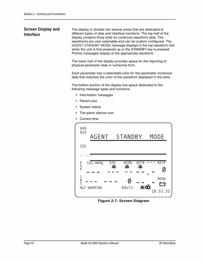
The display is divided into several areas that are dedicated to different types of data and interface functions. The top half of the display contains three slots for continuos waveform data. The waveforms are user selectable and can be custom configured. The AGENT STANDBY MODE message displays in the top waveform slot when the unit is first powered up or the STANDBY key is pressed. Priority messages display at the appropriate waveform.
The lower half of the display provides space for the reporting of physical parameter data in numerical form.
Each parameter has a selectable color for the parameter numerical data that matches the color of the waveform displayed in the slots.
The bottom portion of the display has space dedicated to the following message types and functions.
• Information messages
• Patient size
• System status
• The alarm silence icon
• Current time
Figure 2-7: Screen Diagram
CO2
CO2EXP
INS
RESPmmHg 02% N2O% AGT% ---
MENU
18:52:35AGT:WARMING Adult
84%N2O
- - -
---------
-----
--.---.-
- +
AGENT STANDBY MODE
0
0

BC Biomedical Model AA-2005 Operator’s Manual Page 2-7
Section 2 —Controls and Connections
Waveforms The waveform area is located in the top half of the display. The monitor can display up to three waveforms simultaneously. Waveform configurations are described in “Setup Procedure” in Section 3.
PRIMARY AGENT WAVEFORMThe primary agent waveform is displayed in the same units selected for displaying the primary agent numerical data. The waveform is auto-ranging within the slot. This waveform can be generated only from the device’s agent detector data. Secondary agents are not displayed as waveforms.
When the Agt to Monitor is set to a selected agent (manual mode), the abbreviation for that agent appears with the waveform and the numerical values. If Auto is chosen for Agt to Monitor, the monitor displays the abbreviation for the primary gas it detects at the waveform and with the numerical values. If the unit detects no agent, AGT appears in the waveform slot and a dashed line appears with the numerical value.
CAPNOGRAMThe CO2 waveform, capnogram, is displayed in percent units.This waveform is generated from the infrared photo-detector of the agent detector. The maximum range of the capnogram is 12.5%.
BREATH BY BREATH BAR GRAPH (B×B)The label “B×B” appears at the beginning of the graph. The user may select the CO2 data to be displayed as a breath by breath bar graph. The breath by breath data is always displayed in percent. The maximum range of the capnometer bar graph is 12.5%.
OXYGEN WAVEFORMThe maximum range of the oxygen waveform is 100%. The units are always in percent. The waveform is auto-ranging within the slot.
NITROUS OXIDE (N2O)The N2O waveform is derived from the agent detector. The source of the waveform and color matches the source for N2O numerical values. The respiration waveform is auto-ranging within the waveform slot.
NOTE: The source of the respiration numerical value and the respiration waveform can be from independent sources.

Section 2 —Controls and Connections
Page 2-8 Model AA-2005 Operator’s Manual BC Biomedical
NumericalParameter Slots
The parameter slots are below the waveform area. The slots remain in this order from left to right: CO2, O2, N2O, AGT, and RESP.
A bell icon may appear in a numerical parameter box indicating an alarm limit is set to off. The bell icon is red with a white “X” indicating that no audible alarm will sound.
The CO2 numerical parameters slot displays data generated from the agent detector. A bell icon displays to indicate that a CO2 alarm limit is set to off.
The label “Mixed” appears before secondary agent concentrations listed at the bottom of the display. The abbreviated name of the secondary agent is located after the “Mixed” label together with the expired (E) and inspired (I) values.
System Status At the bottom of the display appear system status messages and icons. These include informational messages, patient size, icons for silenced alarms, battery status, secondary agents detected in the system, and system time.

BC Biomedical Model AA-2005 Operator’s Manual Page 3-1
Section 3 —Setup Procedure
Monitor Setup This section provides an overview of the setup procedures for theModel AA-2005 anesthetic agent analyzer.
If the unit is new, preparations such as loading batteries should be performed.
Charging the Monitor The rechargeable battery is a nickel metal hydride battery and is maintenance free. If the battery becomes defective, it should be replaced. Refer to the battery replacement procedure described in the Model AA-2005’s service manual or contact the Service Department.
• Do not short circuit the battery terminals! The resulting high- current discharge can cause burns.
• Do not crack, cut, or burn the internal battery. Contact with battery contents can cause severe burns and eye damage.
Environmental hazard! When replacing the battery, dispose of the old battery in accordance with local and federal laws. Do not incinerate.
• If the electrical integrity of the earth ground is in doubt, the power cord should be disconnected and the machine should be operated from its internal electrical power source.
• Explosion hazard. Keep lighted cigarettes, sparks, and flames away from the battery.
• The battery contains sulfuric acid electrolyte which can cause severe burns and eye damage, as well as illness from sulfur oxide fumes.
• Do not short circuit the battery terminals. The resulting high-current discharge can cause burns.
The device functions if plugged into AC (mains) power while batteries are completely drained. Do not leave defective batteries inside the monitor. The analyzer can also function without batteries, running on AC power only, but this is not recommended in a clinical setting.
Allow the batteries to charge to full strength before using. If the batteries are not fully charged before use, the batteries do not hold as much charge in the future. Insufficient charging also degrades the batteries.
WARNING ! !
Section 3 —Setup Procedure
Page 3-2 Model AA-2005 Operator’s Manual BC Biomedical
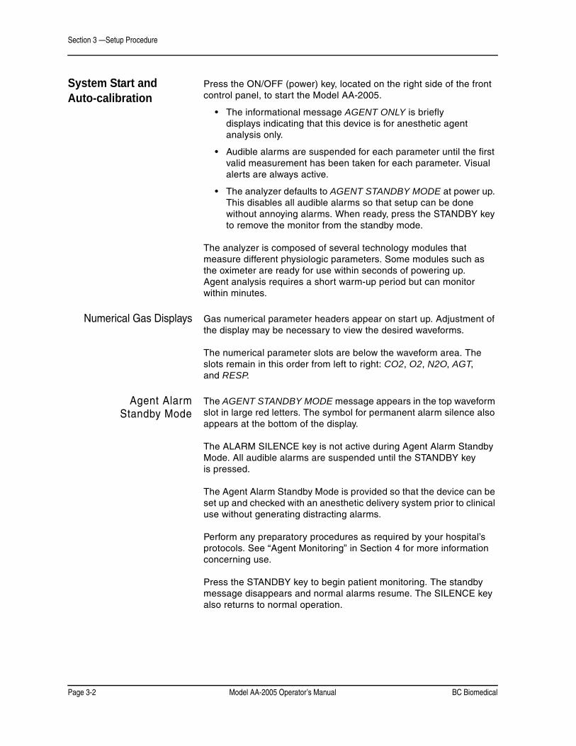
System Start and Auto-calibration
Press the ON/OFF (power) key, located on the right side of the front control panel, to start the Model AA-2005.
• The informational message AGENT ONLY is briefly displays indicating that this device is for anesthetic agent analysis only.
• Audible alarms are suspended for each parameter until the first valid measurement has been taken for each parameter. Visual alerts are always active.
• The analyzer defaults to AGENT STANDBY MODE at power up. This disables all audible alarms so that setup can be done without annoying alarms. When ready, press the STANDBY key to remove the monitor from the standby mode.
The analyzer is composed of several technology modules that measure different physiologic parameters. Some modules such as the oximeter are ready for use within seconds of powering up. Agent analysis requires a short warm-up period but can monitor within minutes.
Numerical Gas Displays Gas numerical parameter headers appear on start up. Adjustment of the display may be necessary to view the desired waveforms.
The numerical parameter slots are below the waveform area. The slots remain in this order from left to right: CO2, O2, N2O, AGT, and RESP.
Agent AlarmStandby Mode
The AGENT STANDBY MODE message appears in the top waveform slot in large red letters. The symbol for permanent alarm silence also appears at the bottom of the display.
The ALARM SILENCE key is not active during Agent Alarm Standby Mode. All audible alarms are suspended until the STANDBY key is pressed.
The Agent Alarm Standby Mode is provided so that the device can be set up and checked with an anesthetic delivery system prior to clinical use without generating distracting alarms.
Perform any preparatory procedures as required by your hospital’s protocols. See “Agent Monitoring” in Section 4 for more information concerning use.
Press the STANDBY key to begin patient monitoring. The standby message disappears and normal alarms resume. The SILENCE key also returns to normal operation.

BC Biomedical Model AA-2005 Operator’s Manual Page 3-3
Section 3 —Setup Procedure
Auto-calibrationand Warm Up
The agent gas detector may require a short warm up period and auto-calibration sequence similar to an internal capnometer. The message AGT:WARMING appears in the information message area. The informational message AGT:MANUAL or AGT:AUTOMATIC also appears indicating that the monitor is in either manual or automatic primary agent identification mode. AGT: AUTO CAL appears to indicate that the agent calibration is in progress.
Respiration waveforms, capnogram, and numerical breath rate are available in one minute from powering the monitor. The monitor reaches full accuracy for agent concentrations in less than 20 minutes.
If the device fails to auto-calibrate upon being plugged in the message AGT:BAD CAL or AGT:CAL MISSING appears. If the unit continues to fail auto-calibration contact the Technical Service Department.
The oxygen monitoring module also requires an auto-calibration sequence and is performed at the same time as the agent detector calibration. If the O2 module fails to auto-calibrate the message O2: SENSOR appears.
Once auto-calibration is complete the monitor displays values for monitored gases.

Section 3 —Setup Procedure
Page 3-4 Model AA-2005 Operator’s Manual BC Biomedical
Display Softkey Functions
Softkeys are selected by turning the rotary knob clockwise or counterclockwise until the desired softkey is highlighted. In the sample below the CO2 softkey is highlighted indicating that the CO2 settings window displays if the menu knob is pressed.
Figure 3-1: Main Screen Menu
If the knob is rotated, the window associated with the highlighted softkey is displayed when the knob is pressed. Knob control goes to that new menu window.
The top item (EXIT) on each menu window automatically highlights when the window is activated. The user may simply press the menu knob a second time to exit each window without making changes.
Agent menus simply allow the user to set alarm settings and waveform and numerical colors. The MENU option opens up a menu that leads to windows to set operation settings.
Changing Settings Turn the rotary knob to highlight items on these menu windows. Press the knob to select the item. A single short beep is generated. The key press beep is audible even when alarms are silenced.
Some of the settings require a letter or number to be entered. Rotate the knob to select the desired character. Press the knob to select the character. Rotate the knob to move to the next character space. If an error is made while entering a text string select the arrow character to back over the existing text.
Alarm Limit Settings Select the CO2, O2, N2O, AGT, and RESP softkeys to set the alarm limits for these parameters. You can also set the alarms settings with the MENU softkey. Select Alarms to set alarm limits for respiration, CO2 Ins, CO2 Exp, O2 Ins, O2 Exp, Apnea, Alarm volume, and Patient size. Select 2nd Alarms to set the High and Low limits for both Inspired and Expired values for the five halogenated gases the device can monitor.
Alarms activate when a high alarm limit is exceeded or the measured value drops below a low alarm limit. High and Low limit values can be set to the same values. In such a case, the monitor alarms when any value but the selected value is measured.
CO2 mmHg O2 % N2O % AGT % RESP
MENU

BC Biomedical Model AA-2005 Operator’s Manual Page 3-5
Section 3 —Setup Procedure
The low limit alarm can never be set higher than the high limit alarm. The high limit adjustment is similarly restricted. When adjusting limit values some of the range may not be available because the device does not display ranges beyond the point that the other limit is set.
The alarm windows appear initially the same for Adult, Pediatric, and Neonate mode. Alarm limits can be set independently and saved, or stored as defaults if desired.
Any changes made are saved to current memory when EXIT is selected.
Colors The colors for the waveforms and numerical displays can be set with the CO2, O2, N2O, and AGT softkeys. Colors can also be set with the MENU softkey under the Parameters option. Color choices are blue, green, red, purple, yellow, white, dark orange, and light orange.
The color sample indicates the current color selected for the display of the numerical values and waveforms for the that monitoring module. The numerical values and the waveforms will always be in matching colors with the exception of the breath by breath display which is always in white.
The colors can be changed as desired.
NOTE: The Agent Color setting indicates waveform color of the user selected primary halogenated agent.

Section 3 —Setup Procedure
Page 3-6 Model AA-2005 Operator’s Manual BC Biomedical
CO2 Softkey This softkey allows the user to set the waveform and numerical Color, Unit of measure, and Alarm Settings for High and Low Expired and Inspired readings of CO2 in the system.
Figure 3-2: CO2 Parameter Menu Window
CO2
CO2EXP
INS
RESPmmHg 02% N2O% AGT% ---
MENU
18:52:35LOW RESP Adult
84%N2O
- - -
---------
-----
--.---.-
- +
ASM
0
EXITCO2 Parameter Menu
ColorUnit of measure mmHg CO2 Alarm SettingsExpired High 55 mmHgExpired Low 5 mmHgInspired High 11 mmHgInspired Low OFF mmHg
0

BC Biomedical Model AA-2005 Operator’s Manual Page 3-7
Section 3 —Setup Procedure
O2 Softkey This softkey allows the user to set the waveform and numerical Color and Alarm Settings for High and Low Expired and Inspired readings of O2 in the system.
Figure 3-3: O2 Parameter Menu Window
CO2
CO2EXP
INS
RESPmmHg 02% N2O% AGT% ---
MENU
18:52:35AGT O2:SENSOR Adult
84%N2O
AGT
---------
-----
--.---.-
- +
ASM
0
EXITO2 Parameter Menu
Color
O2 Alarm SettingsExpired High OFF%Expired Low OFF%Inspired High OFF%Inspired Low OFF%
0

Section 3 —Setup Procedure
Page 3-8 Model AA-2005 Operator’s Manual BC Biomedical
N2O Softkey This softkey allows the user to set the waveform and numerical Color and Alarm Settings for High and Low Expired and Inspired readings of N2O in the system.
Figure 3-4: N2O Parameter Menu Window
The second setting is for the nitrous oxide (N2O) alarm limits. Nitrous oxide has its own set of alarms. The medium priority alarms, LOW INS N2O, HIGH INS N2O, LOW EXP N2O, and HIGH EXP N2O are active unless the limits are individually set to off.
CO2
CO2EXP
INS
RESPmmHg 02% N2O% AGT% ---
MENU
18:52:35AGT WARMING Adult
84%N2O
AGT
---------
-----
--.---.-
- +
ASM
0
EXITN2O Parameter Menu
Color
N2O Alarm SettingsExpired High OFF%Expired Low OFF%Inspired High OFF%Inspired Low OFF%
0
BC Biomedical Model AA-2005 Operator’s Manual Page 3-9
Section 3 —Setup Procedure
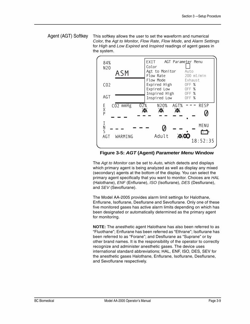
Agent (AGT) Softkey This softkey allows the user to set the waveform and numerical Color, the Agt to Monitor, Flow Rate, Flow Mode, and Alarm Settings for High and Low Expired and Inspired readings of agent gases in the system.
Figure 3-5: AGT (Agent) Parameter Menu Window
The Agt to Monitor can be set to Auto, which detects and displays which primary agent is being analyzed as well as display any mixed (secondary) agents at the bottom of the display. You can select the primary agent specifically that you want to monitor. Choices are HAL (Halothane), ENF (Enflurane), ISO (Isoflurane), DES (Desflurane), and SEV (Sevoflurane).
The Model AA-2005 provides alarm limit settings for Halothane, Enflurane, Isoflurane, Desflurane and Sevoflurane. Only one of these five monitored gases has active alarm limits depending on which has been designated or automatically determined as the primary agent for monitoring.
NOTE: The anesthetic agent Halothane has also been referred to as “Fluothane”; Enflurane has been referred as “Ethrane”; Isoflurane has been referred to as “Forane”; and Desflurane as “Suprane” or by other brand names. It is the responsibility of the operator to correctly recognize and administer anesthetic gases. The device uses international standard abbreviations; HAL, ENF, ISO, DES, SEV for the anesthetic gases Halothane, Enflurane, Isoflurane, Desflurane, and Sevoflurane respectively.
CO2
CO2EXP
INS
RESPmmHg O2% N2O% AGT% ---
MENU
18:52:35AGT WARMING Adult
84%N2O
AGT
---------
-----
--.---.-
- +
ASM
0
EXIT AGT Parameter MenuColorAgt to Monitor AutoFlow Rate 200 ml/minFlow Mode ExhaustExpired High OFF %Expired Low OFF %Inspired High OFF %Inspired Low OFF %
0

Section 3 —Setup Procedure
Page 3-10 Model AA-2005 Operator’s Manual BC Biomedical
The agent high priority alarm WRONG AGENT, the medium priority alarms for LOW INS AGENT, HIGH INS AGENT, LOW EXP AGENT, and HIGH EXP AGENT only apply to the primary agent.
NOTE: Parameter limit alarms for the remaining four monitored non-primary agents are not active even though their numerical values may appear on the main screen as a mixed (secondary) agent. Any halogenated agent not designated or determined as the primary agent (that exceeds its threshold limit) are treated as a component of a mixed gas for alarm purposes.
Respiration(RESP) Softkey
This softkey allows the user to set the High and Low alarm settings for Breaths per minute (Br/m).
Figure 3-6: Respiration Alarm Settings Window
CO2
CO2EXP
INS
RESPmmHg 02% N2O% AGT% ---
MENU
18:52:35AGT O2 SENSOR Adult
84%N2O
AGT
---------
-----
--.---.-
- +
ASM
00
EXITRespiration
Alarm Settings
High 36 Br/m Low 6 Br/m

BC Biomedical Model AA-2005 Operator’s Manual Page 3-11
Section 3 —Setup Procedure
MENU Softkey (System Menus)
This softkey allows access to all the system settings. Selecting this softkey brings up a submenu with menu choices for monitor performance. Menu choices are Display, Configuration, 2nd Configuration, Parameters, Alarms, and 2nd Alarms.
The settings in these windows affect the way physiological data is collected and displayed.
Figure 3-7: MENU Window
Display controls the waveforms display on the top half of the display.
Configuration controls the monitor’s Date and Time and the external communications for the monitor. The Service mode is also initiated from Configuration.
2nd Configuration controls FREEZE key functions as well as monitor Language and Alarm warning.
Parameters control waveform and numerical colors for CO2, O2, agents, and N2O as well as the Unit of measure for CO2, which agent is monitored, Flow Rate, and Flow Mode.
Alarms controls the High and Low alarm limits for respiration, inspired and expired CO2 and O2, apnea time, Alarm Volume, and Patient size.
2nd Alarms controls the High and Low alarm limits for inspired and expired agents.
CO2
CO2EXP
INS
RESPmmHg 02% N2O% AGT% ---
MENU
08:52:35LOW RESP Adult
84%N2O
AGT
---------
-----
--.---.-
- +
ASM
0
0
EXIT
DISPLAYConfiguration2nd ConfigurationParametersALARMS2nd Alarms

Section 3 —Setup Procedure
Page 3-12 Model AA-2005 Operator’s Manual BC Biomedical
Display Window The Display window allows the user to choose what elements are displayed in waveform format
Figure 3-8: Display Menu Window
WAVEFORM TYPEChoices for waveforms are ET CO2, O2, AGT (agent), N2O, BxB, and OFF. Waveform 2 also has the option of Cascade which allows it to “cascade” with Waveform 1.
WAVEFORM DESCRIPTIONThe waveform area is located in the upper left-hand portion of the display. The service tool has the capability to display three waveforms simultaneously. The top waveform slots (1 and 2) are 16 mm in height. Waveform slot 3 is 8 mm in height. Waveform slot 1 goes to 32 mm in height when Cascade is selected for waveform slot 2.
Only waveform 1can be adjusted in size and dimension by using the settings provided when waveform 2 is set to Cascade. The choices for waveform 1 then is 16 mm and 32 mm.
The gain listed on the DISPLAY window settings increases the display size of the waveforms. It does not control the amplification gain of the source signal.
The waveforms displayed are user selectable.
The device displays waveforms in two 16mm slots and one smaller 8mm slots. The 16mm slots can be combined to form a 32mm slots. To combine the slots to form a larger area to display waveforms set the lower slot TYPE to Cascade. The slot above automatically increases in size to fill the space.
CO2
CO2EXP
INS
RESPmmHg 02% N2O% AGT% ---
MENU
18:52:35LOW RESP Adult
84%N2O
- - -
---------
-----
--.---.-
- +
ASM
0
EXIT SWEEPTYPE GAIN MM/SEC SIZE
Waveform 1 N2O x2.0 12.5 16mmWaveform 2 ET CO2 x2.0 12.5 16mmWaveform 3 AGT x1.0 12.5 8mmExternal Display OFF

BC Biomedical Model AA-2005 Operator’s Manual Page 3-13
Section 3 —Setup Procedure
Each waveform slot displays the parameter or source along the left edge of the screen. The colors of the waveforms are also user selectable in the parameter softkey windows. The numerical parameters colors match the selected waveform color.
CASCADEThe unit can cascade a waveform 1 into the next lower slot and it is then displayed as twice its original length.
The cascaded data is a continuous band of waveform using the sweep speed as set in the original waveform slot. The gain and range settings are the same for the entire cascaded waveform. The waveform label and scale are not shown for slots where data has been cascaded from a higher slot.
To cascade a waveform 1 into waveform slot 2, set waveform slot 2 TYPE to Cascade. Waveform 1 automatically cascades into waveform slot 2. Only waveforms 1 and 2 can be linked in cascade.
GAIN AND SWEEPThe GAIN and SWEEP settings found in the DISPLAY menu can also be used to modify the way waveforms are displayed on the screen.
The upper two (12.5mm) slots of the display allow for larger waveforms to display. Gain settings from the upper set of slots do not correspond to the gain settings of the lower slot. In order to obtain identical waveform sizes in the top and bottom slots, set the gain of waveform slot 3 one step higher than the top two slots.
A minimum of four and a half seconds worth of data at a sweep speed of 25mm per second displays. Waveforms can have sweep speeds of 50, 25, 12.5, or 6.25 mm per second.
The user can also set the GAIN, SWEEP MM/SEC, and SIZE of each waveform. Options for GAIN are 0.5, 1.0, 2.0, and 4.0. Options for SWEEP (measured in mm/sec) are 6.25, 12.5, 25.0, and 50.0. SIZE defaults at 16mm for Waveform 1 and Waveform 2 and at 8mm for Waveform 3. Waveform 1 defaults to a size of 32mm when Waveform 2 is set to OFF. Waveform 1 can still be set to 16mm at this point.
If an external display is connected to the device, set the External Display to Big Disp to view the internal display on the larger monitor or Graph to view the enhanced trend display. The default is OFF.

Section 3 —Setup Procedure
Page 3-14 Model AA-2005 Operator’s Manual BC Biomedical
Configuration Use the Configuration menu to set the analyzer configuration.
Figure 3-9: Configuration Menu Window
Rotate the menu knob to set the correct Date and Time for the analyzer. Date is set in day-month-year format with the month abbreviated to its three-letter abbreviation and the year in four-digit format. Time is in military (24 hour) format.
If a Print Device is connected, select Serial. The default is OFF.
Select Serial Format as TEXT, CVP, and CUSP. The default is CUSP. The Baudrate options are 2400, 4800, 9600, 19200, and 38400. The default is 38400.
Analog Out options are ET CO2, O2, AGT (agent), N2O, and OFF. The default is ET CO2.
Interval Print sets periodic automatic printouts as selected by the user in the Configuration menu. The Interval Print only works when an external printer is connected to the device. The selections available for Interval Print are 1, 2, 5, 10, 15, 20, and 30 seconds; 1, 2, 5, 10, 15, 30, and 60 minutes; 2, 4, 8, 12, and 24 hours; and OFF. The default setting is OFF.
Enter Service allows the user to access the service mode. A password is needed to enter the service mode. Options are NO and YES with the default as NO.
CO2
CO2EXP
INS
RESPmmHg 02% N2O% AGT% ---
MENU
18:52:35AGT : O2 : SENSOR Adult
84%N2O
- - -
---------
-----
--.---.-
- +
ASM
0
0
EXIT
Date 16-FEB-2003Time 18:52Print Device OFFSerial Format CUSP Baud Rate 38400Analog Out ET CO2Interval Print OFFEnter Service NO

BC Biomedical Model AA-2005 Operator’s Manual Page 3-15
Section 3 —Setup Procedure
2nd Configuration Use the 2nd Configuration menu to set more monitor configurations.
Figure 3-10: 2nd Configuration Menu Window
Enter Simulation allows the user to access the simulation mode. A password is needed to enter the simulation mode. Options are NO and YES with the default as NO.
Freeze timeout determines how long the waveforms are “frozen” when the FREEZE key is pressed. Monitoring still continues numerically and waveforms collected during the “freeze” are viewable in the Trend data. Options are 30 seconds, 1 to 5 minutes, and OFF. The default is 2 min.
Language determines the language the display appears in. Options are ENGLISH, SPANISH, GERMAN, FRENCH, ITALIAN, and PORTUG. (Portuguese). The default is ENGLISH.
Factory Default allows the user to revert to the factory default settings. Options are NO and YES. The default is NO.
Alarm warning allows the user to turn the alarm warning ON or OFF. A password is needed to set the alarm warning. The default is ON.
CO2
CO2EXP
INS
RESPmmHg 02% N2O% AGT% ---
MENU
08:52:35LOW RESP Adult
84%N2O
- - -
- - -- - -- - -
- - -- -
- -. -- -. -
- +
ASM
0
EXITEnter Simulation NOFreeze timeout 2 minLanguage ENGLISHFactory Default NOAlarm warning ON

Section 3 —Setup Procedure
Page 3-16 Model AA-2005 Operator’s Manual BC Biomedical
Parameters This menu allows the user to set display qualities on the monitor.
Figure 3-11: Parameters Menu Window
AGENT COLORThis is the color of the primary agent waveform and numerical values when setting the primary agent manually. Color choices are blue, green, red, purple, yellow, white, dark orange, and light orange.
The Unit of measure for CO2 can also be set in this menu.
PRIMARY AGENT SELECTIONAgt to Monitor sets whether the analyzer automatically detects and records primary agent data (Auto) or the user can select a primary agent to monitor. If the agent used is not the agent selected for monitoring, a WRONG AGENT message appears. Choices are Auto, HAL (Halothane), ENF (Enflurane), ISO (Isoflurane), DES (Desflurane), and SEV (Sevoflurane). The default is Auto.
The primary agent for monitoring must be correctly entered depending on the monitoring alarm characteristic desired by the user. The unit has two modes of agent gas monitoring. The user may select a specific halogenated agent to be designated as the primary agent. The user may otherwise set the monitor to automatically detect and identify the current primary gas of a mixture.
CO2
CO2EXP
INS
RESPmmHg 02% N2O% AGT% ---
MENU
18:52:35LOW RESP Adult
84%N2O
AGT
---------
-----
--.---.-
- +
ASM
0
EXITCO2 Color Unit of measure mmHgO2 Color Agent Color Agt to Monitor Auto Flow Rate 200 ml/min Flow Mode ExhaustN2O Color
0

BC Biomedical Model AA-2005 Operator’s Manual Page 3-17
Section 3 —Setup Procedure
• Always confirm the primary agent selection before use. Incorrect primary agent setting may result in erroneous limit alarms. Alarm characteristics of the monitor are altered when automatic primary agent detection is activated.
• Never substitute a primary agent setting for a different halogenated agent, or any agent not listed! The agent detection is specific to the listed gases only.
• The alarm, WRONG AGENT, appears when the primary agent (that is manually selected by the physician) does not match the primary agent detected. The WRONG AGENT alarm is deactivated when automatic primary agent detection is selected.
• The halogenated agent waveform and waveform label may automatically change to a different halogenated agent when automatic primary agent detection is used. If no primary agent is detected, dashes appear in the waveform label, when automatic primary agent detection is used.
The selected primary halogenated agent has its own set of alarm limits as described earlier in this section. This is for use when the primary agent is selected manually. When automatic primary agent detection is used, the agent alarm limits are updated at the time of identification from the “Default Alarm Limits by Agent” settings. If the primary agent is redefined automatically, the alarm limits again are updated from the agent specific limits defined in the menu.
The primary agent is the halogenated agent having the highest concentration during mixed gas conditions. Where only one halogenated agent is to be used, the single agent should always be the primary agent. The primary agent can be set to Halothane, Isoflurane, Enflurane, Desflurane, Sevoflurane or automatic.
FLOW RATE SETTINGThe user can also set the Flow Rate for agent gases. Options are 100, 150, and 200ml/min. Default is 200ml/min. The “Flow Rate” setting adjusts the amount of sample gas that is drawn in by the gas monitoring system. When the agent settings are active the flow setting control changes, such that 200, 150, 100 ml/min options are available for selection. Response time decreases with lower flow rates. The default setting of 150ml/min is recommended for general monitoring purposes.
FLOW MODEThe flow mode of the is permanently set to exhaust and cannot be changed.
WARNING ! !

Section 3 —Setup Procedure
Page 3-18 Model AA-2005 Operator’s Manual BC Biomedical
Alarms Alarm settings for all parameters except for agent gases are set in this menu. High and Low settings can be set in this window.
Figure 3-12: Alarm Menu Window
Ranges for alarm settings are described in the following tables.
Table 3-1: Alarm Menu Settings: Adult and Pediatric
Parameter High Low IncrementDefault
HighDefault
Low
Respiration 6-150, OFF 6-150, OFF 1.0 36 OFF
CO2 (mmHg) 0-100, OFF 0-100, OFF 5.0 10 (I) OFF (I)
55 (E) 5 (E)
CO2 (Torr.) 0-94.0, OFF 0-94.0, OFF 0.5 na na
CO2 (%) 0-12.5, OFF 0-12.5, OFF 0.5 na na
CO2 (kPa.) 0-12.5, OFF 0-12.5, OFF 0.5 na na
O2 18-100, OFF 18-100, OFF 1.0 OFF (I) 18 (I)
OFF (E) OFF (E)
CO2
CO2EXP
INS
RESPmmHg 02% N2O% AGT% ---
MENU
18:52:35LOW RESP Adult
84%N2O
AGT
---------
-----
--.---.-
- +
ASM
0
EXITRespiration 36 6CO2 Ins mmHg 12 12CO2 Exp mmHg 55 5O2 Ins % OFF OFFO2 Exp % OFF OFFApnea seconds 20Alarm Volume 5Patient size Adult
HIGH LOW

BC Biomedical Model AA-2005 Operator’s Manual Page 3-19
Section 3 —Setup Procedure
The CO2 parameters can be measured in terms of mmHg, Torr, kPa, or volume percent.
Apnea monitors apnea time and the options are 5 to 60 seconds, in 5 second increments, and OFF. The default is 20 seconds.
The Alarm Volume sets the volume the alarm is heard. The range is 1-10 and OFF. The default is OFF. If the Alarm Volume is set to a value below 2, the unit defaults to 2 when the monitor is powered off and on.
Table 3-2: Alarm Menu Settings: Neonate
Parameter High Low IncrementDefault
HighDefault
Low
Respiration 6-150, OFF 6-150, OFF 1.0 60 14
CO2 (mmHg) 0-100, OFF 0-100, OFF 5.0 10 (I) OFF (I)
55 (E) 5 (E)
CO2 (Torr.) 0-94.0, OFF 0-94.0, OFF 0.5 na na
CO2 (%) 0-12.5, OFF 0-12.5, OFF 0.5 na na
CO2 (kPa.) 0-12.5, OFF 0-12.5, OFF 0.5 na na
O2 18-100, OFF 18-100, OFF 1.0 OFF (I) 18 (I)
OFF (E) OFF (E)

Section 3 —Setup Procedure
Page 3-20 Model AA-2005 Operator’s Manual BC Biomedical
2nd Alarms Alarm settings for agent gases are set in this menu. High and Low settings can be set in this window.
Figure 3-13: 2nd Alarm Menu Window
Ranges for alarm settings are described in the following table.
CO2
CO2EXP
INS
RESPmmHg 02% N2O% AGT% ---
MENU
08:52:35LOW RESP Adult
84%N2O
- - -
---------
-----
--.---.-
- +
ASM
0
EXIT
AGT OFF OFF OFF OFFN20 OFF OFF OFF OFFHAL OFF OFF OFF OFFENF OFF OFF OFF OFFISO OFF OFF OFF OFFDES OFF OFF OFF OFFSEV OFF OFF OFF OFF
Inspired ExpiredHIGH LOW HIGH LOW
Table 3-3: Alarm Settings
Parameter High Low IncrementDefault
HighDefault
Low
AGT (Inspired) 0.1-20.0, OFF 0.1-10.0, OFF 0.1 OFF OFF
(Expired) 0.1-20.0, OFF 0.1-10.0, OFF 0.1 OFF OFF
N2O (Inspired) 20-100 1-50 1 OFF OFF
(Expired) 20-100 1-50 1 OFF OFF
HAL (Inspired) 0.1-20.0, OFF 0.1-20.0, OFF 0.1 OFF OFF
(Expired) 0.1-20.0, OFF 0.1-20.0, OFF 0.1 OFF OFF
ENF (Inspired) 0.1-20.0, OFF 0.1-20.0, OFF 0.1 OFF OFF
(Expired) 0.1-20.0, OFF 0.1-20.0, OFF 0.1 OFF OFF
ISO (Inspired) 0.1-20.0, OFF 0.1-20.0, OFF 0.1 OFF OFF
(Expired) 0.1-20.0, OFF 0.1-20.0, OFF 0.1 OFF OFF
DES (Inspired) 0.1-20.0, OFF 0.1-20.0, OFF 0.1 OFF OFF
(Expired) 0.1-20.0, OFF 0.1-20.0, OFF 0.1 OFF OFF
SEV (Inspired) 0.1-20.0, OFF 0.1-20.0, OFF 0.1 OFF OFF
(Expired) 0.1-20.0, OFF 0.1-20.0, OFF 0.1 OFF OFF

BC Biomedical Model AA-2005 Operator’s Manual Page 3-21
Section 3 —Setup Procedure
N2O COMPENSATIONSince nitrous oxide has a similar infrared signature to that of CO2, and it also affects infrared signature characteristics of CO2, special care must be taken when measuring CO2 while nitrous oxide is being used. There are two forms of N2O compensation with the device. N2O compensation for the internal capnometer and the gas monitor function independently and differently.
A manual form of N2O compensation is provided with the settings for the internal capnometer. Since the capnometer does not measure the amount of N2O present, the compensation is generalized for N2O levels within a 40 to 80 percent range. This feature must be manually activated when N2O is being used.
The device uses a polychromatic infrared technology to measure N2O and CO2 levels independently. The measuring process used in the detector is inherently unaffected by CO2 and N2O mixtures. If the N2O level exceeds its threshold for the detection limit, the monitoring system (when set) can accurately compensate for a range of N2O concentrations.

Section 3 —Setup Procedure
Page 3-22 Model AA-2005 Operator’s Manual BC Biomedical
Factory Defaults
CO2 Settings
O2 Settings
Table 3-4: CO2 Settings
Parameter Range Default
Unit of Measure
ment
Unit of measure mmHg, Torr., %, kPa mmHg
Alarm Settings:
Expired High 0-100, OFF (increments of 5) 55 mmHg
0-94.0, OFF (increments of 0.5) Torr.
0-12.5, OFF (increments of 0.5) %
0-12.5, OFF (increments of 0.5) kPa
Expired Low 0-100, OFF (increments of 5) 5 mmHg
0-94.0, OFF (increments of 0.5) Torr.
0-12.5, OFF (increments of 0.5) %
0-12.5, OFF (increments of 0.5) kPa
Inspired High 0-100, OFF (increments of 5) 10 mmHg
0-94.0, OFF (increments of 0.5) Torr.
0-12.5, OFF (increments of 0.5) %
0-12.5, OFF (increments of 0.5) kPa
Inspired Low 0-100, OFF (increments of 5) OFF mmHg
0-94.0, OFF (increments of 0.5) Torr.
0-12.5, OFF (increments of 0.5) %
0-12.5, OFF (increments of 0.5) kPa
Table 3-5: O2 Settings
Parameter Range DefaultUnit of
Measurement
Alarm Settings:
Expired High 18-100, OFF OFF %
Expired Low 18-100, OFF OFF %
Inspired High 18-100, OFF OFF %
Inspired Low 18-100, OFF 18 %

BC Biomedical Model AA-2005 Operator’s Manual Page 3-23
Section 3 —Setup Procedure
N2O Settings
AGT (Agent) Settings
Table 3-6: N2O Settings
Parameter Range DefaultUnit of
Measurement
Alarm Settings:
Expired High 20-100, OFF OFF %
Expired Low 0.1-20.0, OFF OFF %
Inspired High 20-100, OFF OFF %
Inspired Low 0.1-20.0, OFF OFF %
Table 3-7: Agent Settings
Parameter Selectable Options Factory Default
Agent to Monitor (Primary)
Halothane, Isoflurane, Enflurane, Sevoflurane, Desflurane, Auto-matic
Automatic
Gas Flow Rate 100, 150, 200 mL 200 mL
Flow Mode Exhaust Exhaust
Expired High See “2nd Alarms” on page 3-20. OFF
Expired Low See “2nd Alarms” on page 3-20. OFF
Inspired High See “2nd Alarms” on page 3-20. OFF
Inspired Low See “2nd Alarms” on page 3-20. OFF
Alarm Type Range Adult Pediatric Neonate
Primary Inspired High 0-20.0% 2.3 2.3 2.3
Primary Inspired Low 0-20.0%, Off OFF OFF OFF
Primary Expired High 0-20.0% 1.5 1.5 1.5
Primary Expired Low 0-20.0%, Off OFF OFF OFF
N2O Inspired High 0-99% 75 75 75
N2O Inspired Low 0-99%, Off OFF OFF OFF
N2O Expired High 0-99%, Off OFF OFF OFF
N2O Expired Low 0-99%, Off OFF OFF OFF
HAL Inspired High 0-20.0%, Off 2.3 2.3 2.3
HAL Inspired Low 0-20.0%, Off OFF OFF OFF
HAL Expired High 0-20.0%, Off 1.5 1.5 1.5
HAL Expired Low 0-20.0%, Off OFF OFF OFF
ENF Inspired High 0-20.0%, Off 4.8 4.8 4.8
ENF Inspired Low 0-20.0%, Off OFF OFF OFF
ENF Expired High 0-20.0%, Off 3.2 3.2 3.2
ENF Expired Low 0-20.0%, Off OFF OFF OFF
ISO Inspired High 0-20.0%, Off 3.6 3.6 3.6
ISO Inspired Low 0-20.0%, Off OFF OFF OFF
ISO Expired High 0-20.0%, Off 2.4 2.4 2.4
ISO Expired Low 0-20.0%, Off OFF OFF OFF

Section 3 —Setup Procedure
Page 3-24 Model AA-2005 Operator’s Manual BC Biomedical
RESP (Respiration)Settings
MENU Settings DISPLAY
DES Inspired High 0-20.0%, Off 18.0 18.0 18.0
DES Inspired Low 0-20.0%, Off OFF OFF OFF
DES Expired High 0-20.0%, Off 12.0 12.0 12.0
DES Expired Low 0-20.0%, Off OFF OFF OFF
SEV Inspired High 0-20.0%, Off 5.1 5.1 5.1
SEV Inspired Low 0-20.0%, Off OFF OFF OFF
SEV Expired High 0-20.0%, Off 3.4 3.4 3.4
SEV Expired Low 0-20.0%, Off OFF OFF OFF
Alarm Type Range Adult Pediatric Neonate
Table 3-8: Respiration Settings
Parameter Range DefaultUnit of
Measurement
High 6-150, OFF 36 Br/m
Low 6-150, OFF OFF Br/m
Table 3-9: Display Menu Settings
Waveform Type Gain Sweep Size
Waveform 1: Default ET CO2 x1.0 12.5 16 mm
Range
Waveform 2: Default O2 x1.0 12.5 16 mm
Range
Waveform 3: Default AGT x1.0 12.5 8 mm
Range
External Display: Default OFF
Range

BC Biomedical Model AA-2005 Operator’s Manual Page 3-25
Section 3 —Setup Procedure
CONFIGURATION
2ND CONFIGURATION
PARAMETERS
ALARMS
Table 3-10: Configuration Menu Settings
Parameter Range Default
Date dd-mmm-yyyy dd-mmm-yyyy
Time 00.00-23.59 hh:mm
Print Device Off, Serial Serial
Serial Format TEXT, CSV, CUSP CUSP
Baudrate 2400, 4800, 9600, 19200, 38400 38400
Analog Out Off, ETCO2, O2, Agent, N2O ET CO2
Interval Print 1, 2, 5, 10, 15, 20, 30 seconds; 1, 2, 5, 10, 15, 30, 60 minutes; 2, 4, 8, 12, 24 hours; OFF
OFF
Enter Service Yes, No NO
Table 3-11: Second Configuration Menu Settings
Parameter Range Default
Enter Simulation Yes, No NO
Freeze Timeout 30 seconds, 1, 2, 3, 4, 5 minutes, Off 2 min
Language English, French, German, Spanish, Portuguese, Italian
ENGLISH
Factory Default Yes, No NO
Alarm warning On, Off ON
Table 3-12: Parameters Menu Settings
Parameter Range Default
Unit of measure mmHg
Agt to Monitor Auto
Flow Rate 200 ml/min
Flow Mode Exhaust
Table 3-13: Alarm Menu Settings: Adult and Pediatric
Parameter High Low IncrementDefault
HighDefault
Low
Respiration 6-150, OFF 6-150, OFF 1.0 36 OFF
CO2 (mmHg) 0-100, OFF 0-100, OFF 5.0 10 (INS) OFF (INS)
55 (EXP) 5 (EXP)
CO2 (Torr.) 0-94.0, OFF 0-94.0, OFF 0.5 na na
CO2 (%) 0-12.5, OFF 0-12.5, OFF 0.5 na na
CO2 (kPa.) 0-12.5, OFF 0-12.5, OFF 0.5 na na
O2 18-100, OFF 18-100, OFF 1.0 OFF (INS) 18 (INS)
OFF (EXP) OFF (EXP)

Section 3 —Setup Procedure
Page 3-26 Model AA-2005 Operator’s Manual BC Biomedical
2ND ALARMS
Table 3-14: Alarm Menu Settings: Neonate
Parameter High Low IncrementDefault
HighDefault
Low
Respiration 6-150, OFF 6-150, OFF 1.0 60 14
CO2 (mmHg) 0-100, OFF 0-100, OFF 5.0 10 (INS) OFF (INS)
55 (EXP) 5 (EXP)
CO2 (Torr.) 0-94.0, OFF 0-94.0, OFF 0.5 na na
CO2 (%) 0-12.5, OFF 0-12.5, OFF 0.5 na na
CO2 (kPa.) 0-12.5, OFF 0-12.5, OFF 0.5 na na
O2 18-100, OFF 18-100, OFF 1.0 OFF (INS) 18 (INS)
OFF (EXP) OFF (EXP)
Table 3-15: Second Alarm Menu Settings
Parameter High Low IncrementDefault
HighDefault
Low
AGT (Inspired) 0.1-20.0, OFF 0.1-10.0, OFF 0.1 OFF OFF
(Expired) 0.1-20.0, OFF 0.1-10.0, OFF 0.1 OFF OFF
N2O (Inspired) 20-100 1-50 1 OFF OFF
(Expired) 20-100 1-50 1 OFF OFF
HAL (Inspired) 0.1-20.0, OFF 0.1-20.0, OFF 0.1 OFF OFF
(Expired) 0.1-20.0, OFF 0.1-20.0, OFF 0.1 OFF OFF
ENF (Inspired) 0.1-20.0, OFF 0.1-20.0, OFF 0.1 OFF OFF
(Expired) 0.1-20.0, OFF 0.1-20.0, OFF 0.1 OFF OFF
ISO (Inspired) 0.1-20.0, OFF 0.1-20.0, OFF 0.1 OFF OFF
(Expired) 0.1-20.0, OFF 0.1-20.0, OFF 0.1 OFF OFF
DES (Inspired) 0.1-20.0, OFF 0.1-20.0, OFF 0.1 OFF OFF
(Expired) 0.1-20.0, OFF 0.1-20.0, OFF 0.1 OFF OFF
SEV (Inspired) 0.1-20.0, OFF 0.1-20.0, OFF 0.1 OFF OFF
(Expired) 0.1-20.0, OFF 0.1-20.0, OFF 0.1 OFF OFF

BC Biomedical Model AA-2005 Operator’s Manual Page 4-1
Section 4 — Agent Monitoring
Introduction This section provides instructions for gas sampling connections and monitoring. The user is expected to be fully familiar with monitoring techniques and with the functions of the device before use.
Before you Begin Read the precautions for each measured parameter that appears in this section.
These instructions describe the use of basic sampling devices and accessories that come with Model AA-2005. An extended list of approved accessories can be found in “Accessories” in Appendix A.
The device should always be checked by the user before use for actual monitoring. Perform the following procedure before using the device.
1. Make sure that unit has been fully charged before use. Check that the AC power cord is plugged in for long-term monitoring situations. Check the communications cable for secure connection to the unit.
2. Check the menus and default settings on the unit to confirm that the anesthetic agent analyzer is setup correctly.
3. Examine the accessories for wear, damage or contamination. Replace or disinfect the accessories as required.
4. Select the correct mode of operation (Adult/Pediatric/Neonate) by entering the patient size in the Alarms menu of the MENU window.
• All accessories connected to the analyzer must comply with applicable UL (Underwriters Laboratories) standards and IEC standards for such products.
• Substitution of recommended sensor and sampling accessories may cause inaccurate measurements and degrade patient safety, or may damage the unit.
WARNING ! !

Section 4 —Agent Monitoring
Page 4-2 Model AA-2005 Operator’s Manual BC Biomedical
Gas Monitoring Safety The following instructions describe precautions and contraindications for agent analysis. Use all safety procedures and protocols for anesthetic safety as designated by your health care facility.
• Do not use this device in conjunction with highly flammable anesthetics such as cyclopropane or ether.
• The unit is not intended for monitoring gas mixtures containing methoxyflurane or halogenated hydrocarbons not specifically listed as a monitored gas.
• Environmental pollution of nitrous oxide and halogenated agents may cause accuracy errors. Always use anesthetic gas scavenging systems (AGSS) with the unit.
• Infectious agents may be transferred between patients through the return of the units exhaust to the breathing circuit.
• Never place the unit inside an oxygen tent or any gas containment apparatus.
• Do not use anti-static or electrically conductive breathing tubes in the presence of electrocautery or electrosurgery equipment.
• Gas mixtures of xygen or nitrous oxide with agents such as Halothane, Methoxyflurane or Enflurane can be flammable. Do not operate the agent gas monitor if high ambient agent concentrations or anesthetic gas leaks are suspected.
WARNING ! !
CAUTION ! !

BC Biomedical Model AA-2005 Operator’s Manual Page 4-3
Section 4 —Agent Monitoring
Water Trap Connections The unit has a front-mounted water trap. The trap slides out and can quickly be replaced if it becomes occluded. Use the designated water trap for this device (BC20-43001). The water trap has a fitting located at the top that connects into the trap receptacle (gas manifold) of the analyzer. The unit’s gas sampling connection (from the water trap) accepts gas sampling lines using the male Luer style connections.
The attachment location of the sampling line is shown below with the water trap properly inserted. This sampling line (BC20-43000) is used for agent gas monitoring with the Model AA-2005. Use the gas sampling accessories only as directed.
Figure 4-1: Sampling Line Connection
Startup and Calibration Allow the unit to warm up and auto-calibrate before use. It is necessary to have the water trap and sampling line attached so that the unit draws the correct air flow.
The unit automatically begins an auto-calibration sequence when powered up. During calibration the unit displays flat waveforms for gas concentrations. When the calibration and warm up sequence is over normal operation begins. See “Setup Procedure” in Section 3 for more information about zero calibrations.
FreezeDefault
TrendPrint
Stand By
On/Off
Alarm/SilenceCO2
CO2EXP
INS
RESP
mmHg 02% N2O% AGT% ---
MENU
08:52:35
AGT:WARMINGAdult
84%N2O
- - -
- - - - - -- - -
- - -
- - - -. -- -. -
- +
AGENT STANDBY MODE
0

Section 4 —Agent Monitoring
Page 4-4 Model AA-2005 Operator’s Manual BC Biomedical
Procedure for Gas Monitoring
The following description is provided for general monitoring of single or multiple gas conditions with the Model AA-2005. Read the entire section for complete instructions for monitoring specific gases.
1. Verify the Primary Agent setting in the Parameters menu in the MENU window. The primary agent may be designated by the user or set to automatic identification.
2. Check the Flow Rate setting in the Parameters menu in the MENU window.
3. Slide the water trap into the trap receptacle.
4. Attach a scavenging line to the rear exhaust port of the unit if anesthetic agents are being used.
5. Attach a sample line to the Luer connector located on the front of the water trap.
6. Make sure there are no kinks or other obstructions in the line extending from the water trap.
7. Attach the sampling device to the sampling line.
8. Replace sampling devices, lines, and water traps if they become blocked.
Occlusions The analyzer displays a visual message AGT: OCCLUSION if the gas sampling system is blocked. The Model AA-2005 momentarily attempts to clear a blockage automatically drawing it into the collection basin of the water trap. If the sampling line or water trap becomes completely blocked, replace the sample line and/or the water trap. There is a brief interruption in gas monitoring during automatic occlusion clearing.
The unit displays NO EXHAUST if the scavenging line is blocked.

BC Biomedical Model AA-2005 Operator’s Manual Page 4-5
Section 4 —Agent Monitoring
Anesthetic Gas Measurement
Allow the unit to warm up and auto-calibrate before use. Connect one end of the sample line to the water trap that is attached to the AA-2005 and the other end of the sample line to the endotracheal connector. Connect the endotracheal connector to the common gas outlet on the anesthesia machine or the vaporizer outlet, if testing a standalone vaporizer. Refer to the vaporizer OEM for specific testing procedures, which may include the carrier gas to be used, the flow rate of the carrier gas, the dial settings to be tested along with the acceptable concentration tolerances for each of the dial settings.
Anesthetic AgentIdentification and
Quantification
The unit is an agent-specific monitor, which means that it is capable of simultaneously distinguishing between and quantifying various halogenated anesthetic agents. The halogenated agents which can be identified and simultaneously quantified at any given time are Halothane, Enflurane, Isoflurane, Desflurane, and Sevoflurane.
Nitrous oxide and carbon dioxide are also identified and quantified and their effect in quantifying mixtures with the five halogenated agents is negligible. The presence of ethyl alcohol, metabolic ketones, helium, and acetone do not interfere with the agent detector and does not significantly affect accuracy. If any anesthetic agent other than those specified for monitoring is present, it won’t be identified and may interfere with reported agent concentrations.
Primary Agent If a waveform for a halogenated agent displays, it is the primary agent that was manually selected in the Parameter menu of the MENU window, or the primary agent as determined through automatic detection. The abbreviation for the agent also appears above the values in the gas numerical slots. The abbreviation for the agent also appears at the beginning of the agent waveform channel.
The primary agent is the halogenated agent having the highest concentration during mixed gas conditions. The primary agent can be set to Halothane, Isoflurane, Enflurane, Desflurane, Sevoflurane, or automatic. See “Setup Procedure” in Section 3 for additional information and precautions for setting the primary agent.
User SelectedPrimary Agent
When the unit is manually set for a specific primary agent, the alarms are keyed to the halogenated agent selected. The alarm limit levels are the current primary alarm limits and should be manually updated if a new primary agent is selected. The current agent alarm limits do not change while monitoring unless done manually.
The WRONG AGENT alarm are active and the unit continually checks for an incorrect agent. If another halogenated agent exceeds the selected primary agent, a high priority alarm occurs. If the agent is being displayed in a waveform, the alarm message appears in large red text in the waveform slot. If the WRONG AGENT alarm appears, immediately check the anesthetic delivery system for incorrect anesthetic gases.

Section 4 —Agent Monitoring
Page 4-6 Model AA-2005 Operator’s Manual BC Biomedical
When the user selects a specific halogenated agent as the primary, that is the agent that always displays in the waveforms. A flat line appears when the halogenated agent is not present.
Automatic PrimaryAgent Detection
The primary agent is identified by the unit as the agent with the highest current concentration. In mixed gas conditions the primary agent may change as the measured gas concentrations change. The waveform and waveform heading also change to the new agent. When the unit is set for automatic primary agent detection, the alarms adjust to the current primary agent as defined in the Alarms menu (see “Setup Procedure” in Section 3). The alarm limits update to those specified for whichever agent is currently at the higher concentration.
Secondary AgentDetection
When more than one halogenated agent is detected above its threshold limits the second highest halogenated agent is identified as a secondary agent. The MIXED AGENT message is activated at the bottom of the display. Measurements for secondary agent expired and inspired values appear. The secondary agent is automatically identified by its three letter abbreviation.
DURING AUTOMATIC PRIMARY AGENT SELECTIONIf the primary agent concentration falls and/or is exceeded by another agent, the primary agent may become the secondary agent when automatic primary agent selection mode is used. The three letter agent name and values for the secondary agent may switch with the primary agent when the concentration of one agent exceeds another.
MIXED AGENT CONDITIONSThe message MIXED AGENT appears as a medium level alarm whenever more than one halogenated agent is detected. The alarm is active whether automatic or manual primary agent selection is used. There are no concentration limit alarms associated with the secondary agent that displays. The presence of additional halogenated agents below the concentration of the secondary agent is not reported by the anesthetic agent analyzer.
Agent IdentificationThresholds
To identify an agent the concentration of the agent individually or in mixture must be above the identification threshold limit. A secondary agent is considered part of a mix if that agent is above its mix threshold limit.

BC Biomedical Model AA-2005 Operator’s Manual Page 4-7
Section 4 —Agent Monitoring
Interfering Gasses ForAnesthetic Agents
The unit reports small changes in agent concentrations when anesthetic agents and other gasses are used. Expected agent changes are provided here for the purpose of comparison.
Table 4-1: For Gas Mixtures of 2% Halothane
Agents Balance Change of Halothane
Helium 50% N2 48% 0.0%
N2O 80% N2 18% +0.1%
CO2 5% N2 93% -0.1%
Ethanol 1% N2 97% -0.1%
Acetone 1% N2 97% -0.1%
Enflurane 5% N2 93% +0.2%
Isoflurane 5% N2 93% +0.2%
Desflurane 5% N2 93% +0.3%
Sevoflurane 5%% N2 93% +0.5%
Table 4-2: For Gas Mixtures of 2% Enflurane
Agents Balance Change of Enflurane
Helium 50% N2 48% 0.0%
N2O 80% N2 18% +0.1%
CO2 5% N2 93% -0.1%
Ethanol 1% N2 97% -0.1%
Acetone 1% N2 97% -0.1%
Halothane 5% N2 93% -0.1%
Isoflurane 5% N2 93% +0.1%
Desflurane 5% N2 93% -0.2%
Sevoflurane 5%% N2 93% -0.1%

Section 4 —Agent Monitoring
Page 4-8 Model AA-2005 Operator’s Manual BC Biomedical
Table 4-3: For Gas Mixtures of 2% Isoflurane
Agents Balance Change of Isoflurane
Helium 50% N2 48% 0.0%
N2O 80% N2 18% +0.1%
CO2 5% N2 93% -0.1%
Ethanol 1% N2 97% -0.1%
Acetone 1% N2 97% 0.0%
Halothane 5% N2 93% -0.4%
Enflurane 5% N2 93% 0.0%
Desflurane 5% N2 93% +0.1%
Sevoflurane 5%% N2 93% -0.3%
Table 4-4: For Gas Mixtures of 2% Desflurane
Agents Balance Change of Desflurane
Helium 50% N2 48% 0.0%
N2O 80% N2 18% +0.1%
CO2 5% N2 93% 0.0%
Ethanol 1% N2 97% -0.1%
Acetone 1% N2 97% 0.0%
Halothane 5% N2 93% +0.1%
Enflurane 5% N2 93% +0.1%
Isoflurane 5% N2 93% +0.4%
Sevoflurane 5%% N2 93% -0.1%
Table 4-5: For Gas Mixtures of 2% Sevoflurane
Agents Balance Change of Sevoflurane
Helium 50% N2 48% 0.0%
N2O 80% N2 18% 0.0%
CO2 5% N2 93% -0.1%
Ethanol 1% N2 97% -0.1%
Acetone 1% N2 97% 0.0%
Halothane 5% N2 93% -0.1%
Enflurane 5% N2 93% -0.1%
Isoflurane 5% N2 93% -0.1%
Desflurane 5%% N2 93% -0.1%

BC Biomedical Model AA-2005 Operator’s Manual Page 4-9
Section 4 —Agent Monitoring
CO2 Monitoring
(Capnometry)
When a sampling device is connected, the unit begins displaying the end-tidal and inspired CO2 values in the parameter box. The capnogram, CO2 waveform, if selected as a displayed waveform, will provide a graphic representation of the patient’s respiration cycle.
The primary source of the numerical respiration rate is determined from the capnogram. The respiration source can be set in the Parameters menu of the MENU softkey window of the unit to “smart switch” between using the capnograph or ECG impedance respiration. A capnograph waveform is displayed using the agent detector data.
The numerical respiration displayed value can be manually set to the capnogram source if desired. The anesthetic agent analyzer can also generate a breath by breath bar chart in the waveform slots that can graphically indicate the relative strength of each breath.
INTERFERING GASSES FOR CO2The unit reports small changes in CO2 when anesthetic agents and other gasses are used. Expected CO2 changes are provided here for the purpose of comparison.
* Gas mixtures balanced with nitrogen.
The Model AA-2005 automatically compensates for the presence of N2O. The table above indicates interference after this compensation has occurred.
Table 4-6: For Gas Mixtures of 5% CO2
Agent Agent Volume* Change of CO2
Oxygen 95% -0.1%
N2O 89% +0.2%
Halothane 3% +0.2%
Enflurane 5% +0.2%
Isoflurane 5% +0.1%
Sevoflurane 5% +0.2%
Desflurane 15% +0.2%
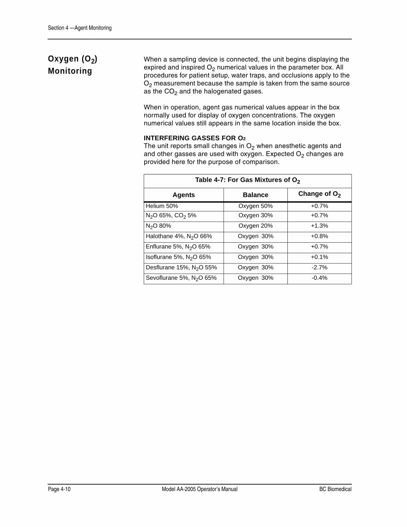
Section 4 —Agent Monitoring
Page 4-10 Model AA-2005 Operator’s Manual BC Biomedical
Oxygen (O2)
Monitoring
When a sampling device is connected, the unit begins displaying the expired and inspired O2 numerical values in the parameter box. All procedures for patient setup, water traps, and occlusions apply to the O2 measurement because the sample is taken from the same source as the CO2 and the halogenated gases.
When in operation, agent gas numerical values appear in the box normally used for display of oxygen concentrations. The oxygen numerical values still appears in the same location inside the box.
INTERFERING GASSES FOR O2
The unit reports small changes in O2 when anesthetic agents and and other gasses are used with oxygen. Expected O2 changes are provided here for the purpose of comparison.
Table 4-7: For Gas Mixtures of O2
Agents Balance Change of O2
Helium 50% Oxygen 50% +0.7%
N2O 65%, CO2 5% Oxygen 30% +0.7%
N2O 80% Oxygen 20% +1.3%
Halothane 4%, N2O 66% Oxygen 30% +0.8%
Enflurane 5%, N2O 65% Oxygen 30% +0.7%
Isoflurane 5%, N2O 65% Oxygen 30% +0.1%
Desflurane 15%, N2O 55% Oxygen 30% -2.7%
Sevoflurane 5%, N2O 65% Oxygen 30% -0.4%
BC Biomedical Model AA-2005 Operator’s Manual Page 5-1
Section 5 — Alarms and Messages
Alarm Description The Model AA-2005 provides both audible and visible alarm indicators to alert the operator of status alarms and physiological parameter alarms. All alarms conform to EN 475 requirements and are produced by the unit.
Message Categories HIGH PRIORITY ALARMSThe high priority audible alarm consists of a pair of bursts. Each burst consists of five tone pulses. The pair of bursts repeat every eight seconds. For each burst there is a short delay between the third and fourth pulse. The frequency of each pulse is 1000 Hz such that the high priority alarm has the highest pitch tone produced by the unit.
The text message appears as red characters in the waveform slot.
MEDIUM PRIORITY AUDIBLE ALARMSEach burst consists of three pulses. The frequency is 800 Hz and the repeat cycle is approximately 25 seconds. The text message appears as yellow characters in the waveform slot or in the information box or in the waveform slot as described later in this section.
LOW PRIORITY AUDIBLE ALARMSEach burst consists of two pulses. The frequency is 350 Hz and the repeat cycle is 15 seconds. The text message appears as yellow characters in the information box.
INFORMATIONAL MESSAGESInformational text messages appear as yellow characters in the information box. There is no alarm tone.
Physiological Alarms Alarms are provided for all monitored parameters. Each parameter limit alarm condition triggers both audible and visible alarms until one of the following events occurs:
• The parameter value returns to within the alarm limit.
• The alarm limit is set beyond the present parameter value.
• The ALARM SILENCE key is pressed. (Audible alarms only).
• The monitor is placed in Standby Mode.
Visible text alarms appear on the display screen.
FLASHING NUMERICAL PARAMETERSIf a physiological parameter exceeds a high limit or falls below a low limit value the numerical value display flashes. This function cannot be suspended and is visible when pop up menus are activated.

Section 5 —Alarms and Messages
Page 5-2 Model AA-2005 Operator’s Manual BC Biomedical
Visual Alerts TEXT MESSAGESThere is space for one line of text at the bottom of the screen. Multiple messages alternate in this space.
Low priority alarms and informational messages always display in the text boxes.
For the vital signs that have a waveform display, medium and high level alarms appear with the waveform. For parameters that do not have a waveform displayed, all level of alarms are reported in the alarm text boxes near the bottom of the screen.
The informational, low, and medium priority text messages are colored yellow and the high alarm messages are red.
VISUAL ALERTS IN WAVEFORM SLOTSWhen a high or medium alarm occurs for a vital sign that has an active waveform, the message displays in the top center of the waveform in large text. If there are multiple alerts to display in a waveform slot, the messages alternate.
If the waveform exists in multiple slots, either through cascade or duplicate waveforms from alternate sources, the waveform slot messages only occur in the top most slot.
Waveform slot messages are not visible during the following conditions.
• The waveform is not selected to be displayed.
• A pop-up window or menu covers the slot.
• Auto-calibration of the gas monitor.
If a high or medium level alarm message cannot be displayed in the waveform slot due to a pop up window, the alarm message displays in the priority text box near the bottom of the screen.
SUSPENDED ALARM ICONSA red bell icon with a “X” indicates that an alarm limit has been turned to “OFF” when the icon occurs in the numerical parameter poxes.
When the red bell icon appears in the top of the first waveform slot, all the monitor’s audible alarms have been silenced. The duration of the silence condition appears to the right of the bell icon.
2 min = 2 minutes = permanent
Visual alarms continue to be displayed as described.
BC Biomedical Model AA-2005 Operator’s Manual Page 5-3
Section 5 —Alarms and Messages
Alarms at Start Up Audible alarms do not occur until the first valid measurement has occurred for that parameter. Visual messages and alarms are present immediately when a module is activated.
Low Battery Alert The Low Battery Alert has its own audible alarm burst that is distinguished from the low priority alarm by its lower pitch and slower repeat cycle. Each burst consists of two pulses with a 300Hz frequency and the repeat cycle of approximately five minutes. The text message appears as yellow characters in the information box (lower text box).
Alarm Messages List Included here is a list of messages and warnings that may appear in the waveform channels or the two alarm message lines located on the display screen.
Respiration Alarms Alarms and messages for respiration may be generated by more than one sampling technology module.
Priority Description
LOW RESP Medium The respiration value has dropped below the value set in the Alarms or RESP menu.
HIGH RESP Medium The respiration value has exceeded the value set in the Alarms or RESP menu.
CO2 Alarms and MessagesPriority Description
CO2:NO BREATH High No breath detected. Check sampling device and adjust placement if necessary. May indicate a leak in the breathing circuit.
LOW ETCO2 Medium The end-tidal CO2 value has dropped below the value set in the Alarms or CO2 menu.
HIGH ETCO2 Medium The end-tidal CO2 value has exceeded the value set in the Alarms or CO2 menu.
LOW INCO2 Medium The inspired CO2 value has dropped below the value set in the Alarms or CO2 menu.
HIGH INCO2 Medium The inspired CO2 value has exceeded the value set in the Alarms or CO2 menu.
CO2:OCCLUSION Medium The sampling line or trap to the capnometer is completely blocked. Replace sampling accessories as needed.
CO2:INSERT TRAP Medium The trap on the unit is not inserted. Trap is partially blocked, wrong type of trap, or defective. Replace trap.

Section 5 —Alarms and Messages
Page 5-4 Model AA-2005 Operator’s Manual BC Biomedical
Priority Description
CO2:ZEROCAL Low The device is calibrating the gas module to current ambient conditions. Monitoring is suspended.
CO2:HI AMBIENT Low There is an excessive amount of CO2 in the ambient air measurement. May indicate a calibration problem. Contact the Service Department.
CO2:NO EXHAUST Low Scavenging line on the unit is blocked or the scavenging system is defective. Remove blockage or correct gas scavenging system.
CO2:FCAL ERROR Low The unit has detected a fault with the gas calibration table for the capnometer. Contact the Service Department.
CO2:UCAL ERROR Low The unit has detected a fault with the user calibration of the internal capnometer. Perform a user calibration. Contact the Service Department if the problem continues.
CO2:ERROR Low Invalid factory calibration of the internal capnometer. Contact the Service Department.
CO2:BENCH FAIL Low The monitor has detected a fault with the internal capnometer. Contact the Service Department.
Agent Gas Alarmsand Messages
Priority Description
AGT:NO BREATH High No breath detected. Check sampling device and adjust placement if necessary. May indicate a leak in the breathing circuit.
WRONG AGENT High The primary agent that the operator has selected does not match the highest concentration agent detected by the analyzer. Check the primary agent setting and the agent delivery system immediately. This alarm is not active when automatic primary agent detection is selected.
MIXED AGENT Medium More than one halogenated agent is present.
LOW INS AGENT Medium The inspired agent value has dropped below the value set in the 2nd Alarms or AGT menu.
HIGH INS AGENT Medium The inspired agent value has exceeded the value set in the 2nd Alarms or AGT menu.
LOW EXP AGENT Medium The expired agent value has dropped below the value set in the 2nd Alarms or AGT menu.
HIGH EXP AGENT Medium The expired agent value has exceeded the value set in the 2nd Alarms or AGT menu.

BC Biomedical Model AA-2005 Operator’s Manual Page 5-5
Section 5 —Alarms and Messages
Priority Description
LOW INS N2O Medium The inspired N2O value has dropped below the value set in the 2nd Alarms or N2O menu.
HIGH INS N2O Medium The inspired N2O value has exceeded the value set in the 2nd Alarms or N2O menu.
LOW EXP N2O Medium The expired N2O value has dropped below the value set in the 2nd Alarms or N2O menu.
HIGH EXP N2O Medium The expired N2O value has exceeded the value set in the 2nd Alarms or N2O menu.
AGT:OCCLUSION Medium The sampling line or water trap to the unit is completely blocked. The unit will attempt to clear the block by drawing the occlusion into the water trap. Replace sampling line as necessary.
AGT:INSERT TRAP Medium The water trap on the unit is not inserted. Trap is partially blocked, wrong type of trap, or defective. Replace the trap.
AGT: NO EXHAUST Low Scavenging line on the unit is blocked or the scavenging system is defective. Remove blockage or correct gas scavenging system.
AGT: BENCH FAIL Low The unit as detected a hardware failure. Contact the Service Department.
AGT:IR FAIL Low The unit as detected a hardware failure. Contact the Service Department.
AGT:PNEUMATICS Low The unit as detected a hardware failure. Contact the Service Department.
AGT: BADCAL Low The unit was unable to calibrate the agent gas detector. Contact the Service Department.
AGT: MISSING CAL Low The unit was unable to calibrate the agent gas detector. Contact the Service Department.
AGT: WARMING Informational The unit has not attained full accuracy for agent concentrations.
AGT:MANUAL Informational The unit is set to manual identification of a selected primary agent. The WRONG AGENT warning appears if the selected agent does not match the detected primary agent.
AGT:AUTOMATIC Informational The unit is set to automatic identification of the current primary agent.

Section 5 —Alarms and Messages
Page 5-6 Model AA-2005 Operator’s Manual BC Biomedical
Oxygen Monitoring(O2) Alarms
Priority Description
LOW ETO2 Medium The expired O2 value has dropped below the value set in the Alarms or O2 menu.
HIGH ETO2 Medium The expired O2 value has exceeded the value set in the Alarms or O2 menu.
LOW INO2 Medium The inspired O2 value has dropped below the value set in the Alarms or O2 menu.
HIGH INO2 Medium The inspired O2 value has exceeded the value set in the Alarms or O2 menu.
O2:SENSOR Low The O2 cell inside the unit is expended and requires replacement. Contact Technical Service.
O2:FCAL ERROR Low The analyzer has detected a fault in the O2 calibration data. Perform a gain and delay adjustment. The O2 cell of the unit may be expired. Contact the Service Department if the problem continues.
O2:UCAL ERROR Low The unit has detected a fault with the user calibration of the internal oxygen monitoring module. Perform a user calibration. Contact the Service Department if the problem continues.
Other MessagesPriority Description
LOW BATTERY Special* Battery power is low. Recharge batteries.
WAVEFORMS FROZEN Informational The user has selected the waveforms to be frozen.Press the FREEZE key again to resume normal display.
* LOW BATTERY has unique alarm characteristics, see page 5-3.
• Additional alarms may alternate with any of the alarms listed in this section. At no time does any alarm, message or alert cause another message to not be displayed.
CAUTION ! !

BC Biomedical Model AA-2005 Operator’s Manual Page 6-1
Section 6 — Trends
Description The trend memory stores data at regular intervals for review at a later time. Trend data can be reviewed by printing it out on an external printer connected to the Model AA-2005.
To view the tabular trend, press the TREND key and the table appears in the right side of the waveform display.
Trend Interval To change the trend interval press and hold the TREND key while viewing the tabular trend. A second window appears. Change the trend to the desired interval by rotating the knob.
Trend data for each parameter is stored every 30 seconds at the zero and 30 seconds mark. Trend data is sampled every ten seconds and the three samples are averaged and stored in trend memory every 30 seconds.
Capacity The trend memory can store up to 24 hours of trend data at 30 second intervals.
When the trend memory is filled to maximum capacity, the new trend data begins to overwrite the oldest trend data in the memory.
Trend Screen Update The table is not updated while it is being viewed. Scroll up to view data that is recorded after the trend screen is activated. The trend screen automatically returns to the main screen after 45 seconds.

Section 6 —Trends
Page 6-2 Model AA-2005 Operator’s Manual BC Biomedical
Trend Setup The trends may be viewed in graphical format in the trend window. Up to two parameters may be viewed in graphical format.
The trend view may be changed in the trend setup window.
Figure 6-1: Trend Setup Window
To view trends:
1. Press the TREND key to enter the trend window.
2. Either the Tabular or Graphical Trend appears.
3. Press and hold the TREND key to enter the trend settings.
4. Set the trend type to Graphical or Tabular.
5. If Graphical is selected, set the Trend Interval as desired.
6. EXIT the trend setting window. Press the TREND key to view the trend displays.
7. Rotate the knob clockwise to see older data.
8. Press the TREND key to exit trends.
NOTE: The trend setting window defaults to Tabular trend. The setting for Trend Interval is not visible until the Trend Type is set to Graphical.
CO2
CO2EXP
INS
RESPmmHg 02% N2O% AGT% ---
MENU
18:52:35AGT WARMING Adult
84%N2O
- - -
---------
-----
--.---.-
- +
ASM
0
EXIT
Trend Type TabularTrend Interval 30 secClear Trends NO
0

BC Biomedical Model AA-2005 Operator’s Manual Page 6-3
Section 6 —Trends
Graphical Trends The graphical trend window covers the upper right corner. The physiological parameter and the unit of measurement is listed horizontally on the first two rows.
The graphical trend window displays for about 45 seconds before timing out. The trend window does not update automatically. The trend window updates each time it is accessed.
The most current data is always displayed on the top. Time stamps for the selected Trend Interval are indicated to the left of the line graphs.
Scrolling The Graph The trend window can be set to display up to 24 hours of data. Rotate the knob clockwise to scroll the graph to show older data. Rotate the knob counter-clockwise to scroll back towards the most current data.
The rate of advance varies with the selected Trend Interval.
Trend Interval Minutes per each click 2 hours 14 hours 28 hours 3
12 hours 424 hours 4
The time stamps update each time the knob is rotated. It is not possible to scroll past the current time.
The trend graph resets to the current time stamp upon exiting to the main screen and returning to the trend window. The trend graph remains at the selected time location while entering and returning from the trend settings window.
Interruption Due ToPower Cycling
The graphical trend has gaps due to power cycling of the analyzer. If the period of missing data is within the last 24 hour period the gaps appear where the power was turned off.
If the power was turned off for a length period of more than a day, a blank period is inserted between the new and old data. The new data begins on a new window with new time stamps. The gap between the monitoring sessions is equal to the Trend Interval in length.
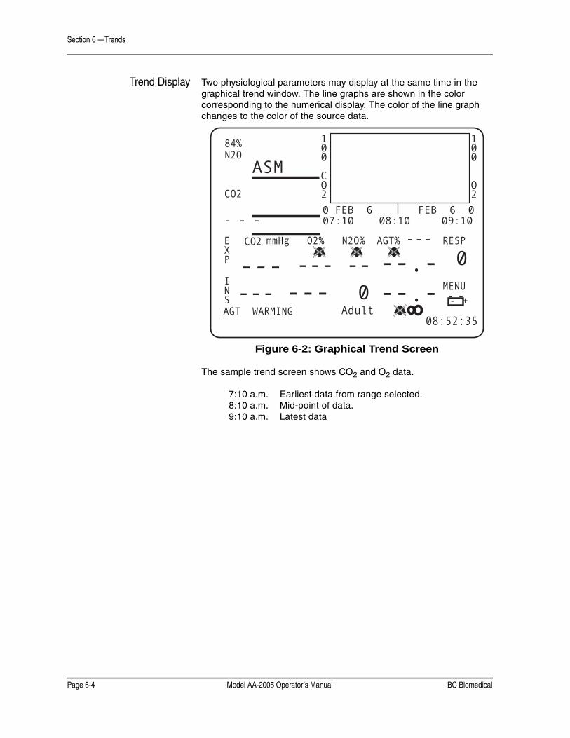
Section 6 —Trends
Page 6-4 Model AA-2005 Operator’s Manual BC Biomedical
Trend Display Two physiological parameters may display at the same time in the graphical trend window. The line graphs are shown in the color corresponding to the numerical display. The color of the line graph changes to the color of the source data.
Figure 6-2: Graphical Trend Screen
The sample trend screen shows CO2 and O2 data.
7:10 a.m. Earliest data from range selected.8:10 a.m. Mid-point of data.9:10 a.m. Latest data
CO2
CO2EXP
INS
RESPmmHg 02% N2O% AGT% ---
MENU
08:52:35AGT WARMING Adult
84%N2O
- - -
---------
-----
--.---.-
- +
ASM
0
100
CO2
100
O2
0 FEB 6 FEB 6 0 07:10 08:10 09:10
0

BC Biomedical Model AA-2005 Operator’s Manual Page 6-5
Section 6 —Trends
Tabular Trends
Tabular Trend Markers Various messages appear in the tabular trend to indicate that system events occurred. A complete list is as follows:
FREEZE ON FREEZE OFFAUDIO ON AUDIO OFFPOWER
NOTE: Permanent silence and 2 minute silence are both recorded as an AUDIO ON/OFF event in the tabular trend table.
Trend Messages The trend also records messages in the trend table that indicates the status of the analyzer at that time. The time and date stamp are also recorded when one of the following messages is recorded. All messages appear in the trend table regardless of the interval selected for the table or the time that the message occurred.
• When the analyzer enters and exits Standby Mode an AUDIO ON or AUDIO OFF message is recorded in the trend table.
• When the analyzer enters and exits Silence Mode an AUDIO ON or AUDIO OFF message is recorded in the trend table. This includes two minute silence and permanent silence conditions.
• When the monitor’s waveforms are “frozen” and “unfrozen,” a FREEZE ON or FREEZE OFF message is recorded in the trend table.
• When the monitor is turned off and on the message POWER is recorded in the trend table.
At midnight the analyzer records the date change into the trend table. This does not occur if the analyzer was turned off at midnight.

Section 6 —Trends
Page 6-6 Model AA-2005 Operator’s Manual BC Biomedical
Data Format The parameters are listed in the first row followed by the units in the second row.
• Measured parameters that exceed or drop below alarm limits are highlighted.
• When a sampling module is on and no value can be determined for the parameter, three dashes “---” display in the trend table.
• If a sampling module is turned off in the Alarm window, the word OFF displays in the trend.
• If a sampling module is turned on and no valid measurement is taken, the word ERR displays in the trend.
• Newest trend data displays at the top of the trend window.
Figure 6-3: Sample Trend Table
The agent (AGT) column denotes the primary agent with the initial letter of the agent name:
• H = Halothane• E = Enflurane• I = Isoflurane• D = Desflurane• S = Sevoflurane• U = Unknown
Clearing the Memory To clear the trend memory:
1. Press the TREND key to display the trend.
2. Press and hold the TREND key again to display the trend setup window.
3. Select the clear trend option and select YES to confirm the clearing of the trend data.
The trend memory is automatically cleared when:
• The time and/or date are changed in the menu
• The patient size is changed (adult/pediatric/neonate).
17MAR CO2 O2 N2O AGT RESP2003 mmHg % % %14:42 E 37 17 39 10.5H 34:00 I 8 21 64 11.014:41 E 37 17 39 10.5H 36:30 I 8 21 64 11.0 14:41
FREEZE OFF:00

BC Biomedical Model AA-2005 Operator’s Manual Page 7-1
Section 7 — Printing and Data Ports
Description The Model AA-2005 is capable of printing all agent gas parameters in tabular (text). The anesthetic agent analyzer can also produce graphical (waveforms) formats as specified by the user. The Model AA-2005 needs an external printer attached to the device to perform printing functions.
Snapshot Size The period of time (in a graphical print) that starts 4.5 seconds prior to pressing the PRINT key and lasting the duration of the "Snapshot" setting in the print menu. (i.e. if the print type is set to graphical and snapshot is set to 6 seconds then the unit prints out the waveform data selected 4.5 seconds prior to a PRINT keypress and 1.5 seconds after the PRINT keypress).
History Size History size is a period of time defined by the user that is prior to the snapshot time period. History size can be selected as 6 or 12 seconds.
Print Modes
Demand Print If the print type is set to tabular pressing the PRINT key causes an immediate print-out of the vital signs numbers, date, time, and patient data in a “tabular” text format.
If the print type is set to graphical pressing the PRINT key causes an immediate print-out of the selected waveforms for a duration as selected by “snapshot size.”
Freeze Print A freeze print is initiated by depressing the PRINT key after setting the monitor in “Freeze” mode (pressing the FREEZE key). The printout is determined by the settings in the Print menu. This strip represents the history size added to the snapshot data.
If print type is set to graphical, the waveforms selected are printed out. The data printed is for a history time period followed by a snapshot time period.
If print type is set to tabular, a demand tabular print is issued using the “frozen” numeric vital signs data on the screen.
Trend Print After displaying a trend on the unit's screen (by pressing the TREND key), depressing the PRINT key causes a trend print of the data displayed on the screen.
Depressing and holding the PRINT key (while a trend displays on the monitor’s screen) causes all of the stored Trend data to print out.

Section 7 —Printing and Data Ports
Page 7-2 Model AA-2005 Operator’s Manual BC Biomedical
Print Formats
Tabular Printing A header is printed containing the device model, the operating software revision, the time and date, and the patient information. The title for each parameter follows.
The format of the TEXT print is as follows:
TIME RESP ETCO2 INCO2 ETO2 INO2 AGT EXP AGT INS N2O EXP N2O INS03:13:44 60* 37 8 mmHg 17 % 21 % HAL 11.0 % 10.5 % 39 % 64 %
Numerical values for all current parameters are printed. The sample below shows a tabular print out.
Graphical Printing If both waveform 1 and 2 have been set to a physical parameter the print out is a split dual waveform. If only one of the waveforms is turned on, a single waveform is printed using the entire waveform area. If both waveforms are turned off, the waveform area of the print out is blank.
Selectable options for waveforms are ET CO2, O2, AGT (agent), N2O, BxB, and OFF.
Numerical values for respiration, ETCO2, INCO2, ETO2, INO2 and agent gases are printed below the waveform grid.

BC Biomedical Model AA-2005 Operator’s Manual Page 7-3
Section 7 —Printing and Data Ports
Data Output Ports The unit supports a variety of communication connections. The communications ports are located along the left edge of the back of the device. The ports are as follows:
• COM1 Port, RS232 Serial DB-9
• COM2 Port, MiniDIN 8, Service/Analog
• Video Port
COM1 Port The unit uses a serial port (DB-9 female) for the external data output port. The monitor uses a standard RS232 communication protocol with a full hardware handshake.
Figure 7-1: COM1 Pinout Diagram
SERIAL PRINTINGThe COM 1 port supports sending data to an external serial printer or computer terminal. To send the data as described in the beginning of this section to the COM 1 port, the print device must be set to Serial in the Configuration menu. Printing, except for trend printing, is then routed to the COM1 port.
Set the serial format to “TEXT” in the Configuration menu to simulate the tabular printout. Set the serial format to “CSV” in the Configuration menu to create a “comma separated variable” table. The CSV format can be used by software programs. A description of the CSV format is located at the end of this section.
SENDING DATA TO A COMPUTERUse a standard null modem serial cable to connector to the computer.A common computer terminal program and an unused RS232 serial port is needed for external communications.
Pinout,DB-9 connector
Pin Signal1 (Unused)2 RX13 TX14 DTR5 Ground6 DSR7 RTS8 CTS9 (Unused)
PINOUT CHART
1 2 3 4 56 7 8 9

Section 7 —Printing and Data Ports
Page 7-4 Model AA-2005 Operator’s Manual BC Biomedical
BC Biomedical recommends using the Windows HYPERTRM.EXE program provided with MS Windows 95/98. HYPERTRM.EXE can be found in the Windows accessory directory. For older computers using MS Windows 3.1, the communications program TERMINAL.EXE can be found in the Windows directory.
Set the analyzer to interval printing with serial output selected. With the computer terminal connected, a data file may be collected. The file may then be further evaluated by computer. See the description for CSV format at the end of this section.
TERMINAL CONFIGURATIONThe cable connections should be completed and the terminal program should be configured before attempting to send data.
The recommended settings are as follows:Baud Rate: 9600 or 19200
Parity: No ParityStop Bits: 1Data Bits: 8
Hardware Control: None
EXTERNAL SERIAL PRINTER ACCESORYThe Seiko DPU-414 is pinned out as a modem would be (DCE - data communications equipment) rather than as a typical printer/computer (DTE - data terminal equipment). Use a null modem serial cable to connect the analyzer to the printer.
A standard DB-9 serial connector is located on the back of the DPU-414 thermal printer. Read the manual provided with the printer kit for additional instructions.
Configure the selected external printer so that it can communicate with the unit. Follow the configuration instructions provided with your printer.
The required settings are as follows:
Baud Rate: 9600 or 19200Parity: No Parity
Stop Bits: 1Data Bits: 8

BC Biomedical Model AA-2005 Operator’s Manual Page 7-5
Section 7 —Printing and Data Ports
COM2 Port The unit uses of the COM2 serial port (8-pin Mini DIN) for loading system software updates and for reprogramming. The communications ability of this port are for service use only. Software is downloaded using the Download Station. Contact Customer Service for more information about the software loader.
There is also an analog output signal available at pin 2. For information about sending analog data to a plotter or chart recorder contact Technical Support.
The connector pinouts are shown below.
Figure 7-2: COM2 Port Pinout Diagram.
Video Port The analyzer has a DB-15 VGA video port that is functional on monitors with TFT screens. Contact customer service for more information about remote video screens approved for use with this device.
41 2
5
8
76
3
Pinout,DIN8 connector
Pin Signal1 Boot 22 Analog Wave3 RX 24 Ground5 TXL6 TX37 RX38 Boot 1
PINOUT CHART

Section 7 —Printing and Data Ports
Page 7-6 Model AA-2005 Operator’s Manual BC Biomedical
CSV Data Format The Comma-Separated Variable output presents the data in a form that is easily imported into a spreadsheet application where further analysis can be done on the data. The data is output in ASCII format with each field (time, expired and inspired CO2, expired and inspired O2, expired and inspired N2O, respiration, and expired and inspired agent gases) separated with a comma. Using the Windows 3.1 TERMINAL.EXE program and EXCEL (4.0), here is an example of how it may be used:
1. Connect the COM1 port to the serial port on the computer.
2. Start Terminal from the Accessories menu.
3. Choose Settings|Communications to set the computer's connector to the proper port. Check communications settings.
4. Choose Transfers|Receive Text File. Assign a name to the data (e.g. DATA.TXT) and press OK.
5. At this point, all data transmitted from the monitor will appear on the screen and will be saved in DATA.TXT.
6. When all the desired data has been accumulated, choose Transfers|Stop to close DATA.TXT.
7. Start EXCEL and choose File|Open.
8. Enter/Click on the file name and press the Text button.
9. For Column Delimiter, choose "Comma". For File Origin, choose "Windows (ANSI)". Then choose OK.
10.Choose OK again from the Open dialog to open and display DATA.TXT.
The data is organized in a table by field. Using the EXCEL presentation options, this data could be graphed, printed in tabular form, or analyzed statistically in some other way.

BC Biomedical Model AA-2005 Operator’s Manual Page 8-1
Section 8 —Maintenance
Cleaning and Disinfecting
• Shock Hazard! Unplug the power cable from the unit before cleaning device.
• Shock Hazard! Never immerse the unit.
• Additional cleaning and maintenance warnings and cautions are listed in the Model AA-2005 Service Manual.
Do not use abrasive cleaners on the unit or on any sensors or probes. Abrasive cleaners can damage the unit, sensors, and probes.
The exterior surface of the unit may be wiped clean with alcohol and dried with a soft, dry cloth. It is best to use a cotton cloth for cleaning.
WARNING ! !

Section 8 —Maintenance
Page 8-2 Model AA-2005 Operator’s Manual BC Biomedical
Accidental Wetting
• Shock Hazard! The unit is AC powered. Saturated electronic devices present a danger to anyone who handles the them.
The action to be taken following accidental wetting of the equipment is as follows:
1. Turn the power off! Disconnect the AC power cord from the unit.
2. Use a clean, dry towel or cloth to remove the liquid from the device housing.
3. The unit should be inspected by an service technician as soon as possible.
4. If the internal mechanism is saturated, allow the liquid to drain out for 24 hours before shipping.
5. If liquid has entered the unit, it needs to be dried and cleaned internally. Full testing is required before the device can be used. Contact the Service Department as soon as possible.
Time is critical! The longer any liquid remains in the device, the more damage it can do. It is important to service the monitor immediately after any liquid spills into it.
Testing and Calibration
Refer to the Model AA-2005 Service Manual for information about calibration and testing.
Safety Testing The unit should be electrically tested annually. Have a qualified service technician perform annually the safety testing listed in the service manual.
• Perform complete functional testing of the unit.
• Test the monitor for electrical safety.
Service Checks If the unit shows any signs of physical damage, return it to the Service Department for repair.
Do not remove the cover. Refer all servicing to a qualified technician. Descriptions of these tests can be found in the Model AA-2005 Service Manual. Some tests may require specialized equipment.
WARNING ! !

BC Biomedical Model AA-2005 Operator’s Manual Page 8-3
Section 8 —Maintenance
Maintenance Schedule
NOTE: Failure to change the O2 cell annually as required in the maintenance schedule may result in damage to the device requiring repair and/or replacement of internal components as a result of degraded O2 cells.
Every Use • Inspect the accessories and cables for damage and proper connection.
• Change the gas sampling device, sampling line.
Every Week • Change the water trap or as needed.
Every 3 Months • Clean the exterior of the unit (or clean as needed).
• Check the O2 cell. Change if necessary.
Every 6 Months • Verify the agent gas auto-calibration. Return for serviceif verification fails.
Every Year • Perform the annual safety tests.
• Change the O2 cell.
• Check the gas flow rate. Adjust if necessary.
• Check the CO2 absorber and replace if necessary.

Section 8 —Maintenance
Page 8-4 Model AA-2005 Operator’s Manual BC Biomedical
Battery Power The unit contains an internal battery that requires exposing internal circuits during replacement. See the service manual for battery replacement procedures.
Expendable Components
The internal oxygen cell (O2 sensor) and carbon dioxide absorber will degrade over time. Replacement requires opening the analyzer’s case and should be performed by a qualified service technician. See the service manual for instructions.
Long-Term Storage No special preparation is necessary for long term storage.
Disposal At the end of its useful life, the unit and its accessories may be disposed of according to your institution’s policies and procedures for disposal of patient-contact medical waste.
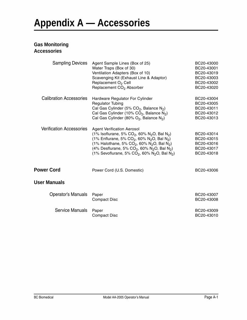
BC Biomedical Model AA-2005 Operator’s Manual Page A-1
Appendix A — Accessories
Gas Monitoring Accessories
Sampling Devices Agent Sample Lines (Box of 25) BC20-43000Water Traps (Box of 30) BC20-43001Ventilation Adapters (Box of 10) BC20-43019Scavenging Kit (Exhaust Line & Adaptor) BC20-43003Replacement O2 Cell BC20-43002Replacement CO2 Absorber BC20-43020
Calibration Accessories Hardware Regulator For Cylinder BC20-43004Regulator Tubing BC20-43005Cal Gas Cylinder (5% CO2, Balance N2) BC20-43011Cal Gas Cylinder (10% CO2, Balance N2) BC20-43012Cal Gas Cylinder (80% O2, Balance N2) BC20-43013
Verification Accessories Agent Verification Aerosol (1% Isoflurane, 5% CO2, 60% N2O, Bal N2) BC20-43014(1% Enflurane, 5% CO2, 60% N2O, Bal N2) BC20-43015(1% Halothane, 5% CO2, 60% N2O, Bal N2) BC20-43016(4% Desflurane, 5% CO2, 60% N2O, Bal N2) BC20-43017(1% Sevoflurane, 5% CO2, 60% N2O, Bal N2) BC20-43018
Power Cord Power Cord (U.S. Domestic) BC20-43006
User Manuals
Operator’s Manuals Paper BC20-43007Compact Disc BC20-43008
Service Manuals Paper BC20-43009Compact Disc BC20-43010