Embed Size (px)
Citation preview

Code_Aster Versiondefault
Titre : Notice d’utilisation des éléments TUYAU_* Date : 03/12/2017 Page : 1/28Responsable : KUDAWOO Ayaovi-Dzifa Clé : U2.02.02 Révision :
a533472fa805
Note of use of the elements TUYAU_*
Summary:
This document is a note of use for modelings TUYAU_3M and TUYAU_6M.
Finite elements TUYAU_3M and TUYAU_6M correspond to linear elements of right piping or curve. Thekinematics of the elements PIPE combine at the same time a kinematics of beam, which describes the overallmovement of the line of piping, and a kinematics of hull, which brings the description of swelling, theovalization and the warping of the cross section.
These modelings are usable for problems of relatively thick three-dimensional pipings, in linear mechanicalanalysis or not linear and small displacements.
Warning : The translation process used on this website is a "Machine Translation". It may be imprecise and inaccurate in whole or in part and isprovided as a convenience.Copyright 2019 EDF R&D - Licensed under the terms of the GNU FDL (http://www.gnu.org/copyleft/fdl.html)

Code_Aster Versiondefault
Titre : Notice d’utilisation des éléments TUYAU_* Date : 03/12/2017 Page : 2/28Responsable : KUDAWOO Ayaovi-Dzifa Clé : U2.02.02 Révision :
a533472fa805
Contents1 Introduction ........................................................................................................................................... 4
2 Capacities of modeling ......................................................................................................................... 5
2.1 Recall of the formulation ................................................................................................................ 5
2.1.1 Geometry of the elements pipes ........................................................................................... 5
2.1.2 Formulation of the elements pipes ....................................................................................... 5
2.2 Comparison with other elements ................................................................................................... 7
2.2.1 Differences between the elements pipes .............................................................................. 7
2.2.2 Differences between the elements pipes and the elements beams ...................................... 7
3 Description of the command sets ......................................................................................................... 9
3.1 Assignment of a modeling and space discretization ...................................................................... 9
3.1.1 Degrees of freedom .............................................................................................................. 9
3.1.2 Mesh support of the matrices of rigidity ................................................................................ 9
3.1.3 Mesh support of the loadings .............................................................................................. 10
3.1.4 Model: AFFE_MODELE ...................................................................................................... 10
3.2 Elementary characteristics: AFFE_CARA_ELEM ........................................................................ 10
3.2.1 Operand MODI_METRIQUE ............................................................................................... 11
3.2.2 Generator and concept of local reference mark : keyword ORIENTATION ........................ 11
3.2.3 Example of assignment of characteristic ............................................................................ 12
3.3 Materials: DEFI_MATERIAU ........................................................................................................ 13
3.4 Limiting loadings and conditions: AFFE_CHAR_MECA and AFFE_CHAR_MECA_F ................. 13
3.4.1 List of the keyword factors ofAFFE_CHAR_MECA and AFFE_CHAR_MECA_F ............... 14
3.4.2 Application of an internal pressure: keyword FORCE_TUYAU ........................................... 15
3.4.3 Application of a force distributed: keyword FORCE_POUTRE ........................................... 15
3.4.4 Application of gravity: keyword GRAVITY (AFFE_CHAR_MECA only) .............................. 16
3.4.5 Connections hull-pipes, 3D-pipe and pipe-beams: keyword LIAISON_ELEM .................... 16
3.4.6 Limiting conditions: keywords DDL_IMPO and LIAISON_* ................................................ 17
3.5 Application of a thermal dilation. .................................................................................................. 18
4 Resolution ........................................................................................................................................... 19
4.1 Linear calculations: MECA_STATIQUE and other linear operators ............................................. 19
4.2 Nonlinear calculations: STAT_NON_LINE and DYNA_NON_LINE ............................................. 19
4.2.1 Behaviors and assumptions of deformations available ...................................................... 19
4.2.2 Details on the points of integration ..................................................................................... 20
4.3 Dynamic calculations ................................................................................................................... 20
5 Additional calculations and postprocessings ...................................................................................... 22
5.1 Elementary calculations of matrices: operator CALC_MATR_ELEM ........................................... 22
5.2 Calculations by elements: operator CALC_CHAMP .................................................................... 22
5.3 Calculations with the nodes: operator CALC_CHAMP ................................................................. 23
5.4 Calculations of quantities on whole or part of the structure: operator POST_ELEM ................... 23
Warning : The translation process used on this website is a "Machine Translation". It may be imprecise and inaccurate in whole or in part and isprovided as a convenience.Copyright 2019 EDF R&D - Licensed under the terms of the GNU FDL (http://www.gnu.org/copyleft/fdl.html)

Code_Aster Versiondefault
Titre : Notice d’utilisation des éléments TUYAU_* Date : 03/12/2017 Page : 3/28Responsable : KUDAWOO Ayaovi-Dzifa Clé : U2.02.02 Révision :
a533472fa805
5.5 Values of components of fields of sizes: operator POST_RELEVE_T ........................................ 23
6 Examples ............................................................................................................................................ 25
6.1 Linear static analysis .................................................................................................................... 25
6.2 Static analysis nonlinear material ................................................................................................ 25
6.3 Modal analysis in dynamics ......................................................................................................... 26
6.4 Nonlinear dynamic analysis ......................................................................................................... 27
7 Bibliographical references .................................................................................................................. 28
Warning : The translation process used on this website is a "Machine Translation". It may be imprecise and inaccurate in whole or in part and isprovided as a convenience.Copyright 2019 EDF R&D - Licensed under the terms of the GNU FDL (http://www.gnu.org/copyleft/fdl.html)

Code_Aster Versiondefault
Titre : Notice d’utilisation des éléments TUYAU_* Date : 03/12/2017 Page : 4/28Responsable : KUDAWOO Ayaovi-Dzifa Clé : U2.02.02 Révision :
a533472fa805
1 IntroductionFinite elements TUYAU_3M and TUYAU_6M correspond to linear elements of right piping or curve. Theyare based on a kinematics of beam of Timoshenko for displacements and rotations of average fibreand on a kinematics of hull for the deformations of the transverse section (ovalization, warping,swelling). These transverse deformations are broken up into Fourier series. Modeling TUYAU_3Mtakes into account 3 modes to the maximum, while modeling TUYAU_6M takes into account 6 modesof Fourier.
These modelings are usable for problems of relatively thick three-dimensional pipings, only in linearmechanical analysis or not linear and small displacements. Currently, no calculation of thermics oracoustics is possible.
This document presents the possibilities of modeling PIPE available in version 6 of Code_Aster. Thepossibilities of this kind of modeling are initially presented, then one briefly points out the formulationof the finite elements and their differences with modelings beam. One also gives the list of the optionsavailable for each element. One finishes by the presentation of some academic CAS-tests and finallysome advices of use are given.
The right or curved pipe sections are gathered under modelings TUYAU_3M and TUYAU_6M. Theoptions of calculations are defined in this document. The current possibilities of these elements pipesare the following ones:
right or curved lines of piping,
linear element with 3 nodes (SEG3) or 4 nodes (SEG4),
relatively thick pipe: e /R0.2 where e represent the thickness and R the ray of thetransverse section,
internal pressure, cross-bendings and anti-plane, torsion and extension,
small displacements,
elastoplastic in constraints plane, or not linear behavior incremental unspecified,
the transverse section can become deformed by: • swelling due to the internal pressure or the effect Fish,• ovalization due to the inflection,• warping due to the inflections combined in the plan and except plan.
Compared with modeling TUYAU_3M, modeling TUYAU_6M a better approximation of the behavior ofthe cross section allows if this one becomes deformed according to a raised mode, for example in thecase of thin tubes where the thickness report on ray of the cross section is 0.1 , and in the caseof plasticity.
Modeling TUYAU_3M have 21 degrees of freedom per node (6 degrees of freedom of beam and 15degrees of freedom of hull), while modeling TUYAU_6M have 39 degrees of freedom per node (6degrees of freedom of beam and 33 degrees of freedom of hull).
For modeling TUYAU_3M, one can use meshs SEG3 and SEG4.
Warning : The translation process used on this website is a "Machine Translation". It may be imprecise and inaccurate in whole or in part and isprovided as a convenience.Copyright 2019 EDF R&D - Licensed under the terms of the GNU FDL (http://www.gnu.org/copyleft/fdl.html)
Code_Aster Versiondefault
Titre : Notice d’utilisation des éléments TUYAU_* Date : 03/12/2017 Page : 5/28Responsable : KUDAWOO Ayaovi-Dzifa Clé : U2.02.02 Révision :
a533472fa805
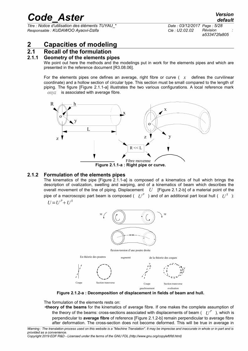
2 Capacities of modeling2.1 Recall of the formulation2.1.1 Geometry of the elements pipes
We point out here the methods and the modelings put in work for the elements pipes and which arepresented in the reference document [R3.08.06].
For the elements pipes one defines an average, right fibre or curve ( x defines the curvilinearcoordinate) and a hollow section of circular type. This section must be small compared to the length ofpiping. The figure [Figure 2.1.1-a] illustrates the two various configurations. A local reference markoxyz is associated with average fibre.
x
y
z
L
h R
R << L
x
y z
Fibre moyenne
o
o
Figure 2.1.1-a : Right pipe or curve.
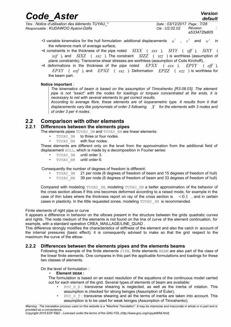
2.1.2 Formulation of the elements pipesThe kinematics of the pipe [Figure 2.1.1-a] is composed of a kinematics of hull which brings thedescription of ovalization, swelling and warping, and of a kinematics of beam which describes theoverall movement of the line of piping. Displacement U [Figure 2.1.2-b] of a material point of the
pipe of a macroscopic part beam is composed ( U P ) and of an additional part local hull ( U S ):
U=U PU S
M M
flexion-torsion d’une poutre droite
En théorie des poutres de la théorie des coques
Coupe Section transverse Section transverse
ovalisation
Coupe
gauchissement
u
w
v
augmenté
w v
Figure 2.1.2-a : Decomposition of displacement in fields of beam and hull.
The formulation of the elements rests on:•theory of the beams for the kinematics of average fibre. If one makes the complete assumption of
the theory of the beams: cross-sections associated with displacements of beam ( U P ), which isperpendicular to average fibre of reference [Figure 2.1.2-b] remain perpendicular to average fibreafter deformation. The cross-section does not become deformed. This will be true in average in
Warning : The translation process used on this website is a "Machine Translation". It may be imprecise and inaccurate in whole or in part and isprovided as a convenience.Copyright 2019 EDF R&D - Licensed under the terms of the GNU FDL (http://www.gnu.org/copyleft/fdl.html)

Code_Aster Versiondefault
Titre : Notice d’utilisation des éléments TUYAU_* Date : 03/12/2017 Page : 6/28Responsable : KUDAWOO Ayaovi-Dzifa Clé : U2.02.02 Révision :
a533472fa805
the element PIPE. One uses the theory of the beams only to describe the movement of averagefibre: the average fibre of the pipe is equivalent to average fibre of a beam. This kinematicsmakes it possible to describe the overall movement of the line of piping.
•theory of the hulls to describe the transverse deformation of the sections around average fibre.Kinematics of the transverse sections: the cross-sections which are perpendicular to averagesurface of reference remain right. The material points located on the normal at not deformedaverage surface remain on a line in the deformed configuration. The formulation used is aformulation of the type LOVE-KIRCHHOFF without transverse shearing for the description of thebehavior of the transverse sections. The thickness of the hull remains constant. Average surface
pipe, located at mid thickness, is equivalent to the average surface of a hull. Thiskinematics of hull brings the description of swelling, the ovalization and the warping of the crosssection.
x
y
z
o o'
Section
L z
y
e
Rext
+
xy
z
x,us,vs ,ws
oo' x,up
y,vp
z,wp
xp
yp
zp
Fibre moyenne
Surface moyenne
Figure 2.1.2-b : Fibre and average surface in the case of a right pipe .
Additional displacements ( U s ) surface of the pipe are approximated by a series of Fourier until the
order M ( M=3 for modeling TUYAU_3M and M=6 for modeling TUYAU_6M).
usx ,=∑
m=2
M
umixcos m∑
m=2
M
um0x sinm
v sx ,=w1
i xsin∑
m=2
M
vmix sinm−w1
0x cos∑
m=2
M
vm0x cosm
w sx ,=w0
∑m=2
M
wmix cos m∑
m=2
M
wm0x sin m
Where
us : represent the axial displacement of average surface in the local reference mark
x
v s : represent the ortho-radial displacement of average surface in the local reference mark
x
w s : represent the radial displacement of average surface in the local reference mark
x
w0 : represent swelling
These elements thus utilize locally:•6 variable kinematics for the beam formulation: displacements u p , v p and w p according
to fibre of reference and rotations around the local axes,
Warning : The translation process used on this website is a "Machine Translation". It may be imprecise and inaccurate in whole or in part and isprovided as a convenience.Copyright 2019 EDF R&D - Licensed under the terms of the GNU FDL (http://www.gnu.org/copyleft/fdl.html)
Code_Aster Versiondefault
Titre : Notice d’utilisation des éléments TUYAU_* Date : 03/12/2017 Page : 7/28Responsable : KUDAWOO Ayaovi-Dzifa Clé : U2.02.02 Révision :
a533472fa805
•3 variable kinematics for the hull formulation: additional displacements us , v s and w s inthe reference mark of average surface,
•4 constraints in the thickness of the pipe noted SIXX ( sxx ), SIYY ( sff ), SIXY (sxf ), and SIXZ ( sxz ). The constraint SIZZ ( szz ) is worthless (assumption of
plane constraints). Transverse shear stresses are worthless (assumption of Coils Kirchoff),•4 deformations in the thickness of the pipe noted EPXX ( exx ), EPYY ( eff ),
EPXY ( exf ), and EPXZ ( sxz ). Deformation EPZZ ( ezz ) is worthless forthe beam part.
Notice important : The kinematics of beam is based on the assumption of Timoshenko [R3.08.03]. The elementpipe is not “exact” with the nodes for loadings or torques concentrated at the ends, it isnecessary to net with several elements to get correct results.According to average fibre, these elements are of isoparametric type. It results from it thatdisplacements vary like polynomials of order 2 following X for the elements with 3 nodes andof order 3 per 4 nodes.
2.2 Comparison with other elements2.2.1 Differences between the elements pipes
The elements pipes TUYAU_3M and TUYAU_6M are linear elements:• TUYAU_3M to three or four nodes.• TUYAU_6M with four nodes.
These elements are different only on the level from the approximation from the additional field ofdisplacement HULL, which is made by a decomposition in Fourier series:
• TUYAU_3M until order 3.• TUYAU_6M until order 6.
Consequently the number of degrees of freedom is different:• TUYAU_3M 21 per node (6 degrees of freedom of beam and 15 degrees of freedom of hull)• TUYAU_6M 39 per node (6 degrees of freedom of beam and 33 degrees of freedom of hull)
Compared with modeling TUYAU_3M, modeling TUYAU_6M a better approximation of the behavior ofthe cross section allows if this one becomes deformed according to a raised mode, for example in thecase of thin tubes where the thickness report on ray of the cross section is 0.1 , and in certaincases in plasticity. In the little requested zones, modeling TUYAU_3M is recommended.
Finite elements of right pipe or curveIt appears a difference in behavior on the elbows present in the structure between the grids quadratic curvesand rights. The node medium of the elements is not found on the line of curve of the element continuation, forexample, with a standard operation CREA_MAILLAGE/LINE_QUAD . This difference strongly modifies the characteristics of stiffness of the element and also the catch in account ofthe internal pressures (basic effect); it is consequently advised to make so that the grid respect to themaximum the curve of the elbow.
2.2.2 Differences between the elements pipes and the elements beamsFollowing the example of the finite elements PIPE, finite elements BEAM are also part of the class ofthe linear finite elements. One compares in this part the applicable formulations and loadings for thesetwo classes of elements.
On the level of formulation :• Element BEAM :The formulation is based on an exact resolution of the equations of the continuous model carriedout for each element of the grid. Several types of elements of beam are available:
• POU_D_E : transverse shearing is neglected, as well as the inertia of rotation. Thisassumption is checked for strong twinges (Assumption of Euler),
• POU_D_T : transverse shearing and all the terms of inertia are taken into account. Thisassumption is to be used for weak twinges (Assumption of Timoshenko).
Warning : The translation process used on this website is a "Machine Translation". It may be imprecise and inaccurate in whole or in part and isprovided as a convenience.Copyright 2019 EDF R&D - Licensed under the terms of the GNU FDL (http://www.gnu.org/copyleft/fdl.html)

Code_Aster Versiondefault
Titre : Notice d’utilisation des éléments TUYAU_* Date : 03/12/2017 Page : 8/28Responsable : KUDAWOO Ayaovi-Dzifa Clé : U2.02.02 Révision :
a533472fa805
These elements use meshs of the type SEG2 with 6 degrees of freedom by nodes, 3displacements and three rotations. The formulation of these elements is presented in thereference document [R3.08.01]. The section is constant, the only possible behavior of thetransverse sections is the translation and rotation for the whole of the points of the section.Section perhaps of an unspecified form the constant or variable over the length.
• Element PIPE :The formulation combines at the same time a beam formulation based on the assumption ofTimoshenko and a hull formulation based on the assumption of Love_Kirchhoff making it possibleto model the phenomena of swelling, ovalization and warping. The hollow section, of circularform, is constant over the entire length of the element. The element is not “exact” with the nodesfor loadings or torques concentrated at the ends, it is thus necessary to net with several elementsto get correct results, in particular to represent the curve.These elements use meshs of the type SEG3 or SEG4 with, for the kinematics of beam 6 degreesof freedom by nodes, 3 displacements and three rotations, and for the kinematics from hull, 15 or33 degrees of freedom of type displacement.
On the level of applicable loadings :• Element BEAM :The possible loadings are the loadings of extension, inflection and torsion. The internal loading ofpressure for the hollow sections does not exist (the section is indeformable).• Element PIPE :The element PIPE admits the classical loadings of beam as well as the application of an internalpressure.
Warning : The translation process used on this website is a "Machine Translation". It may be imprecise and inaccurate in whole or in part and isprovided as a convenience.Copyright 2019 EDF R&D - Licensed under the terms of the GNU FDL (http://www.gnu.org/copyleft/fdl.html)

Code_Aster Versiondefault
Titre : Notice d’utilisation des éléments TUYAU_* Date : 03/12/2017 Page : 9/28Responsable : KUDAWOO Ayaovi-Dzifa Clé : U2.02.02 Révision :
a533472fa805
3 Description of the command sets3.1 Assignment of a modeling and space discretization
In this part, one describes the choice and the assignment of one of two modelings PIPE as well as thedegrees of freedom and the associated meshs. Most described information are extracted from thedocumentation of use [U3.11.06]: Modelings TUYAU_3M and TUYAU_6M.
3.1.1 Degrees of freedomThe degrees of freedom are, in each node of the mesh support:
• six components of displacement of average fibre (three translations and three rotations),• three degrees of freedom corresponding to modes 0 and 1,• for each mode of Fourier, 6 degrees of freedom ( U corresponds to warping, V and
W with ovalization: V with orthoradial displacement, W with radial displacement,
I mean “in plane” and O mean “out of plane”).
Element Degrees of freedom to each node top RemarksTUYAU_3M DX DY DZ Value of the component of
displacement in translation imposed on the specified nodes
DRX DRYMARTINI
DRZ Value of the component of displacement in rotation imposed on the specified nodes
W0 WI1 WO1 Degree of freedom of swelling and mode 1 on W
UI2 VI2 WI2 UO2 VO2 WO2 Degrees of freedom related to mode 2
UI3 VI3 WI3 UO3 VO3 WO3 Degrees of freedom related to mode 3
TUYAU_6M DX DY DZ Value of the component of displacement in imposed translation
DRX DRYMARTINI
DRZ Value of the component of displacement in imposed rotation
W0 WI1 WO1 degrees of freedom of swelling and mode 1 on W
UI2 VI2 WI2 UO2 VO2 WO2 degrees of freedom related to mode 2
UI3 VI3 WI3 UO3 VO3 WO3 degrees of freedom related to mode 3
UI4 VI4 WI4 UO4 VO4 WO4 degrees of freedom related to mode 4
UI5 VI5 WI5 UO5 VO5 WO5 degrees of freedom related to mode 5
UI6 VI6 WI6 UO6 VO6 WO6 degrees of freedom related to mode 6
3.1.2 Mesh support of the matrices of rigidityThe meshs support of the finite elements, in displacement formulation, are segments with 3 or 4nodes.
Modeling Mesh Finite element RemarksTUYAU_3M SEG3 METUSEG3 Linear mesh
SEG4 MET3SEG4 Linear meshTUYAU_6M SEG3 MET6SEG3 Linear mesh
Warning : The translation process used on this website is a "Machine Translation". It may be imprecise and inaccurate in whole or in part and isprovided as a convenience.Copyright 2019 EDF R&D - Licensed under the terms of the GNU FDL (http://www.gnu.org/copyleft/fdl.html)

Code_Aster Versiondefault
Titre : Notice d’utilisation des éléments TUYAU_* Date : 03/12/2017 Page : 10/28Responsable : KUDAWOO Ayaovi-Dzifa Clé : U2.02.02 Révision :
a533472fa805
Meshs SEG4, which has cubic functions of forms, were developed to solve a simple problem of beamin inflection. For this simple example, the exact solution is obtained using one only element with meshSEG4.For more complex problems, the experiment shows that one can net much more coarsely with meshsSEG4. For example about fifteen elements are needed SEG3 to obtain a correct solution for an elbowin inflection whereas one needs half with elements of it SEG4.
Note:
One can use the operator MODI_MAILLAGE to build meshs SEG4 starting from meshs SEG3 . 3.1.3 Mesh support of the loadings
All the loadings applicable to the elements used are treated by direct discretization on the meshsupport of the element in displacement formulation. The linear pressure and the other forces as wellas gravity are examples of loadings applying directly to the element. No special mesh of loading isthus necessary.
3.1.4 Model: AFFE_MODELEThe assignment of modeling passes through the operator AFFE_MODELE [U4.41.01]. It is pointed outthat only the mechanical phenomenon is available with the element PIPE.
AFFE_MODELE TUYAU_3MTUYAU_6M
Remarks
AFFE •PHENOMENON ‘MECHANICAL’ •MODELING ‘TUYAU_3M’ •MODELING ‘TUYAU_6M’ •
On the level of the choice of modeling PIPE, one can note that the use of a decomposition in Fourierseries to order 6 (element TUYAU_6M) in the case of improve the approximation of the behavior of thecross section in the presence of local modes, if this one becomes deformed according to a raisedmode, for example thin tubes where the thickness report on ray of the cross section is 0.1 , andin the case of plasticity.
3.2 Elementary characteristics: AFFE_CARA_ELEMIn this part, the operands characteristic of the element pipe are described. The documentation of useof the operator AFFE_CARA_ELEM is [U4.42.01].
AFFE_CARA_ELEM TUYAU_3MTUYAU_6M
Remarks
BEAM •SECTION: ‘CIRCLE’ •% section constant •% section Variable •
MODI_METRIQUE •TUYAU_NCOU tncouch •TUYAU_NSEC tnsec •
ORIENTATION ‘GENE_TUYAU’ • Definition of a generator. By default, a generator is created
PRECISION •CRITERION •
The characteristics which it is possible to affect on the elements PIPE, are:•SECTION: ‘CIRCLE’
The section is defined by its ray ‘R’ external and its thickness ‘EP’, on each mesh since the gridis represented by average fibre of the pipe.
Warning : The translation process used on this website is a "Machine Translation". It may be imprecise and inaccurate in whole or in part and isprovided as a convenience.Copyright 2019 EDF R&D - Licensed under the terms of the GNU FDL (http://www.gnu.org/copyleft/fdl.html)

Code_Aster Versiondefault
Titre : Notice d’utilisation des éléments TUYAU_* Date : 03/12/2017 Page : 11/28Responsable : KUDAWOO Ayaovi-Dzifa Clé : U2.02.02 Révision :
a533472fa805
•TUYAU_NCOU: tncouch It is the number of layers to be used for the integration of the nonlinear relations of behavior in thethickness of the right pipe sections. In linear elasticity, one to two layers are enough, intononlinear one advises to put between 3 and 5 layers. The number of point of Gauss is equal totwice the number of layers plus one 2×tncouch1 , with the result that time CPUincreases quickly with the number of the layers.
•TUYAU_NSEC: tnsec It is the number of angular sectors to use for the integration of the nonlinear relations of behaviorin the circumference of the right pipe sections. By default the number of sectors 16 are worth.One advises to put 32 sectors into nonlinear for precise results (attention with the increase in timeCPU with the number of sectors).
•ORIENTATION (‘GENE_TUYAU’)One defines from one of the nodes ends of the line of piping a continuous line traced on the pipe.Operands PRECISION and CRITERION allow to define the precision for the construction of thegenerator and the limit between a right pipe section and a curved element.
Note:The directing vector of the line thus defined should not be colinéaire with average fibre of the elbowto the node end considered, by using the keyword INFO=2 one can check if the definite vector iscorrect.
3.2.1 Operand MODI_METRIQUEThe operand MODI_METRIQUE allows to define for the elements PIPE the type of integration in thethickness:•MODI_METRIQUE = ‘NOT’ conduit to assimilate in integrations the ray to the average radius. This
is thus valid for the pipes low thickness (compared to ray),•MODI_METRIQUE = ‘YES’ imply a complete, more precise integration for thick pipings, but being
able in certain cases to lead to oscillations of the solution.
3.2.2 Generator and concept of local reference mark : keyword ORIENTATIONThe generator traced throughout piping makes it possible to define the origin of the angles [Figure 2.1.2-b]. This is used:•to interpret the degrees of freedom of ovalization;
• •
• •
• •
1
2 Ligne génératrice
Figure 3.2.2-a : Representation of two noncoplanar elbows connected by a right pipe.
For a transverse section end of the line of piping [Figure 3.2.2-b], the user defines inAFFE_CARA_ELEM under the keyword ORIENTATION a vector whose projection on the transverse
section end defines a vector origin z1 unit.
Syntax is the following one:
AFFE_CARA_ELEM (… ORIENTATION = _F (GROUP_NO = ‘END’, CARA = ‘GENE_TUYAU’ VALE = (X, there, Z)))
Warning : The translation process used on this website is a "Machine Translation". It may be imprecise and inaccurate in whole or in part and isprovided as a convenience.Copyright 2019 EDF R&D - Licensed under the terms of the GNU FDL (http://www.gnu.org/copyleft/fdl.html)

Code_Aster Versiondefault
Titre : Notice d’utilisation des éléments TUYAU_* Date : 03/12/2017 Page : 12/28Responsable : KUDAWOO Ayaovi-Dzifa Clé : U2.02.02 Révision :
a533472fa805
where: END centers transverse section end is the node.x , y , z contains the 3 components of the vector directing the generator of the pipe, with to
project on the transverse section end. This vector must be defined in a node or one group_noend of the pipe. The geometry is then built automatically for all the related elements of PIPE.The intersection between the direction of this vector and the average surface of the elbowdetermines the trace of the generator on this section. One calls x1, y1, z1 the direct trihedron
associated with this section where x1 is the unit vector perpendicular to the transversesection. The intersection enters transverse section and line resulting from the center of thissection directed by zk is the trace of a generator represented below. For the whole of the other
transverse sections, the trihedron xk , yk , zk is obtained either by rotation of the trihedron
xk−1 , yk−1 , z k−1 in the case of the bent parts, is by translation of the trihedron
xk−1 , yk−1 , z k−1 for the right parts of piping.
x1
z1
y1
x2
z2
y2
Figure 3.2.2-b : Representation of the generator of reference.
The origin of commune with all the elements is defined compared to the trace of this generatoron the transverse section. The angle between the trace of the generator and the current position onthe transverse section is located by the angle . The local reference mark of the right and bentpipe is thus defined by the option ORIENTATION (‘GENE_TUYAU’) order AFFE_CARA_ELEM who
allows to define the first vector zk at an end.
x
y
z
Surface moyenne
Trace de la génératrice
Figure 3.2.2-c : Local reference mark of the element XYZ .
3.2.3 Example of assignment of characteristicThis example is a piping comprising two elbows (problem of Hoovgaard resulting from testSSLL101C).
Warning : The translation process used on this website is a "Machine Translation". It may be imprecise and inaccurate in whole or in part and isprovided as a convenience.Copyright 2019 EDF R&D - Licensed under the terms of the GNU FDL (http://www.gnu.org/copyleft/fdl.html)

Code_Aster Versiondefault
Titre : Notice d’utilisation des éléments TUYAU_* Date : 03/12/2017 Page : 13/28Responsable : KUDAWOO Ayaovi-Dzifa Clé : U2.02.02 Révision :
a533472fa805
z
y
x
A
B
10
4
5
5
4
Modélisation TUYAU (SEG3)
C
H
G
F
E
D
Conditions aux limites : Points C et H - DDL de Poutre : DX = DY = DZ = DRX = DRY = DRZ = 0 - DDL de Coque : UIm = VIm = WIm = 0 (m=2,3) UOm = VOm = WOm = 0 (m=2,3) WI1 = WO1 = WO = 0
•diameter external of the pipe: 0.185m•thickness of the pipe: 6.12m•radius of curvature of the elbows: 0.922 m
MODELE=AFFE_MODELE (MAILLAGE=MAILLAGE, AFFE=_F (ALL = ‘YES’, PHENOMENON = ‘MECHANICAL’, MODELING = ‘TUYAU_3M’) )
CARELEM=AFFE_CARA_ELEM (MODELE=MODELE, POUTRE=_F (GROUP_MA = ‘TOUT_ELT’, SECTION = ‘CIRCLE’, CARA = (‘R’, ‘EP’,), VALE = (0.0925, 0.00612,)), ORIENTATION=_F (GROUP_NO = ‘IT, CARA = ‘GENE_TUYAU’, VALE = (1. , 0. , 0. ,)) )
3.3 Materials: DEFI_MATERIAUThe definition of the behavior of a material is carried out using the operator DEFI_MATERIAU[U4.43.01]. There is no particular constraint which had with the use of the elements PIPE.
The materials used with the whole of modelings can have elastic behaviors in plane constraints whoselinear characteristics are constant or function of the temperature. The nonlinear behaviors in planeconstraints are available for modelings pipes. For more information on these nonlinearities one canrefer to [§ 2.6].
DEFI_MATERIAU TUYAU_3M TUYAU_6M RemarksELAS, ELAS_FO, ECRO_LINE, TRACTION,…
• • all materials available in C_PLAN
3.4 Limiting loadings and conditions: AFFE_CHAR_MECA andAFFE_CHAR_MECA_FOne points out that it is not possible to carry out thermal calculations, however the assignment oftemperature is possible, using the operator CREA_CHAMP. (see paragraph [§3.4.4]).
Warning : The translation process used on this website is a "Machine Translation". It may be imprecise and inaccurate in whole or in part and isprovided as a convenience.Copyright 2019 EDF R&D - Licensed under the terms of the GNU FDL (http://www.gnu.org/copyleft/fdl.html)

Code_Aster Versiondefault
Titre : Notice d’utilisation des éléments TUYAU_* Date : 03/12/2017 Page : 14/28Responsable : KUDAWOO Ayaovi-Dzifa Clé : U2.02.02 Révision :
a533472fa805
The assignment of the loadings and the boundary conditions on a mechanical model is carried outusing the operator AFFE_CHAR_MECA, if the loadings and the boundary conditions mechanical on asystem are actual values depending on no parameter, or AFFE_CHAR_MECA_F, if these values arefunctions of the position or the increment of loading.
The documentation of use ofAFFE_CHAR_MECA and AFFE_CHAR_MECA_F is [U4.44.01].
3.4.1 List of the keyword factors ofAFFE_CHAR_MECA and AFFE_CHAR_MECA_FThe keyword factors available for these two operators are gathered in the two following tables.
AFFE_CHAR_MECA TUYAU_3MTUYAU_6M
Goal, remarks and examples
DDL_IMPO • Goal : to impose, with nodes or groups of nodes, one or valuesof displacementMode 0 (swelling) and:
•modes 1 to 3 for TUYAU_3M•modes 1 to 6 for TUYAU_6M
Example : SDLL14, SSLL101, SSLX102, SSNL106,…LIAISON_DDL • Goal : to define a linear relation between degrees of freedom of
two or several nodesLIAISON_OBLIQUE • Goal : to apply, with nodes or groups of nodes, the same
component value of displacement definite per component in anunspecified oblique reference mark
LIAISON_GROUP • Goal : to define linear relations between certain degrees offreedom of couples of nodes, these couples of nodes beingobtained while putting in opposite two lists of meshs or nodes
LIAISON_UNIF • Goal : to impose the same value (unknown) on degrees offreedom of a set of nodesExample : ELSA01B, ELSA01C and ELSA01D
LIAISON_SOLIDE • Goal : to model an indeformable part of a structureExample : ELSA01B, ELSA01C and ELSA01D
LIAISON_ELEM • Goal : to model the connections of a massive part 3D with apipe part or of a hull part with a pipe partExample : SSLX101B, SSLX102A and SSLX102F
LIAISON_CHAMNO • Goal : to define a linear relation between all ddls present in aconcept CHAM_NO
GRAVITY • Goal : to apply an effect of gravityExample : SSLL101, SSLL106
FORCE_POUTRE • Goal : to apply linear forces, to elements of type beamExample : SSLL106
FORCE_NODALE • Goal : to apply, with nodes or groups of nodes, nodal forces,definite component by component in the reference mark TOTALor in an oblique reference mark defined by 3 nautical anglesExample : SSLL106,…
FORCE_TUYAU • Goal : to apply, with elements or groups of elements of typepipe an internal pressureExample : SSLL106, SSNL117, SSNL503
Warning : The translation process used on this website is a "Machine Translation". It may be imprecise and inaccurate in whole or in part and isprovided as a convenience.Copyright 2019 EDF R&D - Licensed under the terms of the GNU FDL (http://www.gnu.org/copyleft/fdl.html)

Code_Aster Versiondefault
Titre : Notice d’utilisation des éléments TUYAU_* Date : 03/12/2017 Page : 15/28Responsable : KUDAWOO Ayaovi-Dzifa Clé : U2.02.02 Révision :
a533472fa805
AFFE_CHAR_MECA_F TUYAU_3MTUYAU_6M
Remarks
DDL_IMPO • See aboveLIAISON_DDL • See aboveLIAISON_OBLIQUE • See aboveLIAISON_GROUP • See aboveLIAISON_UNIF • See aboveLIAISON_SOLIDE • See aboveFORCE_POUTRE • See aboveFORCE_NODALE • See aboveFORCE_TUYAU • See above
3.4.2 Application of an internal pressure: keyword FORCE_TUYAUThis keyword factor is usable to apply an internal pressure to elements pipe, defined by one or moremeshs or of the groups of meshs. The pressure is applied to the level of the internal ray, as in 3D.
Syntax to apply this loading is pointed out below:•AFFE_CHAR_MECA (…
| FORCE_TUYAU =_F ( ♦ / ALL = ‘YES’,/ MESH = lma, [l_maille]/ GROUP_MA = lgma, [l_gr_maille]
♦ NEAR = p, [R])
•AFFE_CHAR_MECA_F (… | FORCE_TUYAU =_F ( ♦ / ALL = ‘YES’,
/ MESH = lma, [l_maille]/ GROUP_MA = lgma, [l_gr_maille]
♦ NEAR = PF, [function])
The operand available is:CLOSE = p (PF)Value of the imposed pressure (real or function of time or the geometry).p is positive according to the contrary direction of the normal to the element.
This loading applies to the types of meshs and following modelings:
Mesh Modeling
SEG3, SEG4SEG3
‘TUYAU_3M’‘TUYAU_6M’
Examples of use are available in the base of tests: CAS-tests ELSA01B, SSLL106A, SSNL117A andSSNL503A.
3.4.3 Application of a force distributed: keyword FORCE_POUTREThis keyword factor is usable to apply forces linear, constants according to X, on elements of typebeam defined on all the grid or one or more meshs or of the groups of meshs. The forces are definedcomponent by component, that is to say in the reference mark TOTAL, that is to say in the localreference mark of the element defined by the operator AFFE_CARA_ELEM [U4.42.01].
Syntax is available in the documentation of AFFE_CHAR_MECA/AFFE_CHAR_MECA_F [U4.44.01]. Thisloading applies to the types of meshs and following modelings:
Mesh Modeling
Warning : The translation process used on this website is a "Machine Translation". It may be imprecise and inaccurate in whole or in part and isprovided as a convenience.Copyright 2019 EDF R&D - Licensed under the terms of the GNU FDL (http://www.gnu.org/copyleft/fdl.html)

Code_Aster Versiondefault
Titre : Notice d’utilisation des éléments TUYAU_* Date : 03/12/2017 Page : 16/28Responsable : KUDAWOO Ayaovi-Dzifa Clé : U2.02.02 Révision :
a533472fa805
SEG3, SEG4SEG3
TUYAU_3MTUYAU_6M
An example of use is available in the base of tests: CAS-test SSLL106.
3.4.4 Application of gravity: keyword GRAVITY (AFFE_CHAR_MECA only)This keyword is used for applied the effect of gravity on piping.
AFFE_CHAR_MECA TUYAU_3MTUYAU_6M
Remarks
GRAVITY (G, ap, LP, CP) • Acceleration and direction of gravity
Example of use of the operand GRAVITY :POI_PROP = AFFE_CHAR_MECA (MODELE=MODELE, PESANTEUR=_F (GRAVITE=9.81, DIRECTION= (0. , 0. , - 1.),), )
3.4.5 Connections hull-pipes, 3D-pipe and pipe-beams: keyword LIAISON_ELEMIt is a question of establishing the connection between a node end of a pipe section and a group ofmesh of edge of elements of hulls or elements 3D. This makes it possible to net part of piping (forexample an elbow) in hulls or elements 3D and the rest in right pipes. The formulation of theconnection hull-pipes and the connection 3D-Pipe is presented in the reference document [R3.08.06].This connection makes it possible to transmit warping and ovalization means of the grid hull or 3D tothe degrees of freedom corresponding of the pipe.
The connection:•Hull-pipe : it makes it possible to connect elements of edge (SEG2, SEG3) hull part with the node of
the pipe to be connected. This connection is currently realizable for pipes whose neutral fibre isperpendicular to the normals with the facets of the plates or the hulls . The connection is usable byusing the keyword LIAISON_ELEM = _F (OPTION = ‘COQ_TUYAU’) of AFFE_CHAR_MECA.
•Pipe-3D : it makes it possible to connect elements of edge (TRIA3, QUAD4, TRIA6,…) part 3D withthe node of the pipe to be connected. The connection is usable by using the keywordLIAISON_ELEM = _F(OPTION = ‘3D_TUYAU’) of AFFE_CHAR_MECA.
Figure 3.4.5-a : Example of connection between a grid COQUE_3D and PIPE.
The cases which test the connections are presented on the following table.
NAME MODELING ELEMENT RemarksELSA01D
Doc. V: [V1.10.119]
POU_D_TDKQTUYAU_3MDIS_TDIS_TR
SEG2
SEG3POI1
Connection COQ_TUYAU :Definition of the rigid bodiesPipe right and bent in dynamics not inéaire
Warning : The translation process used on this website is a "Machine Translation". It may be imprecise and inaccurate in whole or in part and isprovided as a convenience.Copyright 2019 EDF R&D - Licensed under the terms of the GNU FDL (http://www.gnu.org/copyleft/fdl.html)

Code_Aster Versiondefault
Titre : Notice d’utilisation des éléments TUYAU_* Date : 03/12/2017 Page : 17/28Responsable : KUDAWOO Ayaovi-Dzifa Clé : U2.02.02 Révision :
a533472fa805
SSLX101B
Doc. V: [V3.05.101]
DKTPIPEDIS_TR
MEDKQU4METUSEG3POI1
Connection COQ_TUYAU :Pipe right modelled in hulls and beams. This test aims to test the connection hull pipe “COQ_TUYAU“in the presence of unit loadings: traction, inflection and of torsion.
SSLX102A
Doc. V: [V3.05.102]
DKTPIPE
MEDKQU4METUSEG3MEDKQU4METUSEG3
Connection COQ_TUYAU:Piping bent in inflection.
SSNL106F
Doc. V: [V6.02.106]
COQUE_3DTUYAU_3M
QUAD9SEG3
Connection COQ_TUYAU: at each end of the grid hulls, with an elementpipeRight beam in traction and inflection,elastoplastic behavior
SSLX102F
Doc. V: [V3.05.102]
3DPIPE
HEXA20METUSEG3
Connection 3D_TUYAU :Piping bent in inflection: modeling 3D-PIPE, linear relations 3D_PIPE. The elbow is modelled with elements3D.
ZZZZ112C
Doc. V: [V1.01.112]
COQUE_3DTUYAU_3MPOU_D_T
QUAD9SEG4SEG3
Connection COQ_TUYAU: a half of the cylinder is modelled in hulls, other half in elements PIPECylinder under variable pressure
In all these CAS-tests, the results are satisfactory given that part of the noted variations is ascribablewith the fusion of the grid 3D or hulls.
Notice : Connections pipe-beams.It is a question of establishing a connection between one node end of a pipe section and a nodeend of an element of beam. The pipe formulation comprises a kinematics of type beam identicalto the kinematics of the elements beams. There is thus no cut between displacements of typebeam (3 displacements and 3 rotations). The average fibre of the beam and the pipe are thesame ones. By account, the kinematics of the elements of beam in the case of does notunderstand kinematics of hull (the section is indeformable) like the elements pipes, there is thusa cut on the level of the deformation of the transverse section.There does not exist in specific Code_Aster of connection pipe-beam, the connection betweenthese two elements is automatically assured, without intervention of the user, by the nodecommon to the element pipe and the element beam. Nevertheless, some care are to be taken, itis necessary that the transition between the beam and pipe sections is sufficiently distant fromall zones “pipe” or the deformation of the transverse section is significant, i.e. that one shouldconnect only when ovalization is deadened.
To model the pipe tees, one will privilege modelings in elements hull or 3D and, therefore, the use ofconnections of the type COQ_TUYAU or 3D_TUYAU respectively. Concerning the connection hull/pipe,one will privilege his application in the cross-sections instead of the curved sections (one recommendsto off-set the connections in regular zones, therefore right).
3.4.6 Limiting conditions: keywords DDL_IMPO and LIAISON_*The keyword factor DDL_IMPO allows to impose, with nodes introduced by one (at least) of thekeywords: ALL, NODE, GROUP_NO, MESH, GROUP_MA, one or more values of displacement (or certainassociated sizes). According to the name of the operator called, the values are provided directly(AFFE_CHAR_MECA) or via a concept function (AFFE_CHAR_MECA_F).
Operands available for DDL_IMPO, are listed below:•DX DY DZ : Blocking on the component of displacement in translation•DRX DRY MARTINI DRZ : Blocking on the component of displacement in rotation
Warning : The translation process used on this website is a "Machine Translation". It may be imprecise and inaccurate in whole or in part and isprovided as a convenience.Copyright 2019 EDF R&D - Licensed under the terms of the GNU FDL (http://www.gnu.org/copyleft/fdl.html)

Code_Aster Versiondefault
Titre : Notice d’utilisation des éléments TUYAU_* Date : 03/12/2017 Page : 18/28Responsable : KUDAWOO Ayaovi-Dzifa Clé : U2.02.02 Révision :
a533472fa805
If the specified nodes belong to elements ‘TUYAU_3M’ (these elements have 15 degrees of freedomof hull):
U : warping V , W : ovalizationI : “in plane” O : “out of planes”
That is to say:•UI2 VI2 WI2 UO2 VO2 WO2 : degrees of freedom related to mode 2. •UI3 VI3 WI3 UO3 VO3 WO3 : degrees of freedom related to mode 3. •WO WI1 WO1 : degrees of freedom of swelling and mode 1 on W .
If the specified nodes belong to elements ‘TUYAU_6M’ (these elements have 33 degrees of freedomof hull), the following degrees of freedom are added:•UI4 VI4 WI4 UO4 VO4 WO4 : degrees of freedom related to mode 4.•UI5 VI5 WI5 UO5 VO5 WO5 : degrees of freedom related to mode 5.•UI6 VI6 WI6 UO6 VO6 WO6 : degrees of freedom related to mode 6.
3.5 Application of a thermal dilation.No thermal calculation is available with modeling PIPE, it is nevertheless possible to apply a dilation(thermal loading of origin), in the shape of a field of temperature to the nodes, defined by the 3components TEMP, TEMP_INF, TEMP_SUP, of which one deduces the average temperature.
This field will have been beforehand creates using the operator CREA_CHAMP (documentation[U4.72.04]).
CREA_CHAMP TUYAU_3MTUYAU_6M
Remarks
TYPE_CHAM ‘NOEU_TEMP_R’‘NOEU_TEMP_F’
• Field result of type temperature
OPERATIONGRIDMODELAFFE ALL: ‘YES’
GROUP_MAMESHNODEGROUP_NO
• The field is manufactured byassignment of values on nodes ormeshs
NOM_CMP ‘TEMP’ • Names of the components which onewants to affect: temperature
‘TEMP_INF’ • Interior temperature‘TEMP_SUP’ • Outside temperature
The assignment of thermal dilation is carried out using the operator AFFE_MATERIAU (documentation[U4.43.03]).
AFFE_MATERIAU TUYAU_3MTUYAU_6M
Remarks
AFFE_VARCNOM_VARC ‘TEMP’ • Name of the variable of order NOM_CHAM ‘TEMP’ •EVOL temple • temple is the field or the evolution
creates by CREA_CHAMP thenpossibly by CREA_RESU.
VALE_REF temperature of reference
Note:
Warning : The translation process used on this website is a "Machine Translation". It may be imprecise and inaccurate in whole or in part and isprovided as a convenience.Copyright 2019 EDF R&D - Licensed under the terms of the GNU FDL (http://www.gnu.org/copyleft/fdl.html)

Code_Aster Versiondefault
Titre : Notice d’utilisation des éléments TUYAU_* Date : 03/12/2017 Page : 19/28Responsable : KUDAWOO Ayaovi-Dzifa Clé : U2.02.02 Révision :
a533472fa805
If one wants to apply a temperature defined by a function, one can use the operator CREA_RESU(TYPE_RESU=' EVOL_THER',…), document [U4.44.12] to create a concept of the typeEVOL_THER usable in AFFE_MATERIAU.Examples of use are available in the base of tests: CAS-tests ELSA01B, SSLL106A, SSNL117Aand SSNL503A.
The following example is extracted from CAS-test SSLL101C.T EMP = CREA_CHAMP ( GRID = GRID , TYPE_CHAM = ‘NOEU_TEMP_R’ , OPERATION = ‘AFFE’ , AFFE= ( _F ( ALL = ‘YES’ , NOM_CMP = ‘TEMP’ , VALE = 472.22 ) , ) , )TEMPER = CREA_RESU ( OPERATION= ‘AFFE’ , TYPE_RESU= ‘EVOL_THER’ , NOM_CHAM= ‘TEMP’ , AFFE= _F ( INST = 0.0 , CHAM_GD = TEMP ) )AFF_MAT1 = AFFE_MATERIAU ( GRID = GRID , AFFE= _F ( ALL = ‘YES’ , MATER = MATER ) , AFFE_VARC= _F ( ALL = ‘YES’ , EVOL = TEMPER , NOM_VARC = ‘TEMP’ , NOM_CHAM = ‘TEMP’ , VALE_REF = 0.0 ) , )
4 Resolution4.1 Linear calculations: MECA_STATIQUE and other linear operators
Linear calculations are carried out in small deformations. Several linear operators of resolution areavailable:•MECA_STATIQUE : resolution of a problem of static mechanics linear [U4.51.01],•MACRO_ELAS_MULT : calculate linear static answers for various loading cases or modes of Fourier
[U4.51.02],•CALC_MODES : calculation of the values and clean vectors by methods of subspaces or iterations
opposite [U4.52.02],•MODE_ITER_CYCL : calculation of the clean modes of a structure with cyclic symmetry [U4.52.05],•DYNA_LINE_TRAN : calculation of the transitory dynamic response to an unspecified temporal
excitation [U4.53.02].
By defaults, the only computed fields are the fields of displacement DEPL and of constraintSIEF_ELGA. Other fields are available by the operand OPTION (see the options available in theparagraph [§5.2] bearing on the use of CALC_CHAMP).
4.2 Nonlinear calculations: STAT_NON_LINE and DYNA_NON_LINE4.2.1 Behaviors and assumptions of deformations available
Following information is extracted from the documentation of use of the operator STAT_NON_LINE :[U4.51.03].STAT_NON_LINEDYNA_NON_LINE
TUYAU_3MTUYAU_6M
BEHAVIOR RELATION • all behaviors available in C_PLANDEFORMATION SMALL •
Incremental relations of behavior (keyword factor BEHAVIOR) according to the assumption of smalldisplacements and small deformations (keyword DEFORMATION = ‘SMALL’) are only mechanicalnonlinear relations of behavior available for modeling PIPE. These relations of behavior connect the
Warning : The translation process used on this website is a "Machine Translation". It may be imprecise and inaccurate in whole or in part and isprovided as a convenience.Copyright 2019 EDF R&D - Licensed under the terms of the GNU FDL (http://www.gnu.org/copyleft/fdl.html)

Code_Aster Versiondefault
Titre : Notice d’utilisation des éléments TUYAU_* Date : 03/12/2017 Page : 20/28Responsable : KUDAWOO Ayaovi-Dzifa Clé : U2.02.02 Révision :
a533472fa805
rates of deformation to the rates of constraints. The supported nonlinear behaviors are those alreadyexisting in plane constraints defined in the operators STAT_NON_LINE and DYNA_NON_LINE.Moreover, with the method of Borst [R5.03.03], all behaviors 2D (D_PLAN, AXIS) in smalldeformations are usable.
The concept RESULT of STAT_NON_LINE contains stress fields, displacement and internal variable atthe points of integration always calculated at the points of gauss:•SIEF_ELGA : Tensor of the constraints by element at the points of integration in the local reference
mark of the element,•VARI_ELGA : Field of internal variables by element at the points of integration in the local reference
mark of the element,•DEPL : fields of displacements.
Moreover, one call to the operator CALC_CHAMP, gives access other fields. In particular, one can carryout the passage of the constraints and internal variables of the points of Gauss to the nodes to formthe fields SIEF_ELNO and VARI_ELNO (see the paragraph [§5.2]).
A field VARI_… can have several types of components. For example, components of the fieldVARI_ELNO are, for the elements PIPE :
K time: V1 ,V2 ,…..Vn
Where:
K is the number of points of integration total K=2×NCOU1×2×NSEC1N is the number of internal variables and depends on the behavior.
4.2.2 Details on the points of integrationFor linear and non-linear calculations, digital integration is carried out with a method of:•Gauss along average fibre.
The number of points of integration is fixed at 3. For a mesh whose tops are 1 and 2 andnumbered from 1 to 2, the 3 points of gauss are such as first is close to 1, second is at equaldistance from 1 and 2 and the third is closer to 2. It is thus necessary to pay attention to theorientation of the meshs when one looks at the results at the points of gauss 1 and 3. Indeed if theorientation of the mesh is changed and that one numbers it from 2 to 1, the first point of gauss iscloser to 2.
•Simpson in the thickness and on the circumference:•Integration in the thickness is an integration of Simpson at 3 points per layer. The number of
points of integration per layer is fixed at 3, in the middle of the layer, in higher skin and lowerskin of the layer, the two points ends being common with the close layers.
•Integration according to the circumference is an integration of Simpson per sector, each sectorbeing of angle 2 /NSEC . is the angle between the generator and the center ofthe sector. The number of points of integration per sector is fixed at 3, in the middle of thesector, partly higher ( 2/NSEC ) and lower ( −2/NSEC ) sector, the twopoints ends being common with the close sectors.
The number of layers and the number of sectors must be defined by the user starting from thekeywords: TUYAU_NCOU, TUYAU_NSEC of the operator AFFE_CARA_ELEM.For example, with 3 layers and 16 sectors, the number of points of integration per element is2×NCOU1×2×NSEC1×NPG what gives 693 points of integration. For each point of
gauss over the length of the element, one stores information on the layers and for each layer on all thesectors. If one wants information at the point of gauss NG , on the layer NC level NCN (NCN=–1 so lower, NCN=0 if medium, NCN=1 so higher), on the sector NS ,
level NSN ( NSN=– 1 so lower, NSN=0 if medium, NSN=1 so higher), then onelooks at the values searched at the point of integration:
NP = NG−1×2 NCOU1×2NSEC1
2×NCNCN−1×2NSEC12×NSNSN .
4.3 Dynamic calculationsWarning : The translation process used on this website is a "Machine Translation". It may be imprecise and inaccurate in whole or in part and isprovided as a convenience.Copyright 2019 EDF R&D - Licensed under the terms of the GNU FDL (http://www.gnu.org/copyleft/fdl.html)

Code_Aster Versiondefault
Titre : Notice d’utilisation des éléments TUYAU_* Date : 03/12/2017 Page : 21/28Responsable : KUDAWOO Ayaovi-Dzifa Clé : U2.02.02 Révision :
a533472fa805
Concerning dynamic calculations, any specificity due to the finite element PIPE exist.
Warning : The translation process used on this website is a "Machine Translation". It may be imprecise and inaccurate in whole or in part and isprovided as a convenience.Copyright 2019 EDF R&D - Licensed under the terms of the GNU FDL (http://www.gnu.org/copyleft/fdl.html)

Code_Aster Versiondefault
Titre : Notice d’utilisation des éléments TUYAU_* Date : 03/12/2017 Page : 22/28Responsable : KUDAWOO Ayaovi-Dzifa Clé : U2.02.02 Révision :
a533472fa805
5 Additional calculations and postprocessings5.1 Elementary calculations of matrices: operator CALC_MATR_ELEM
The operator CALC_MATR_ELEM (documentation [U4.61.01]) allows to calculate elementary matricesassembled by the order ASSE_MATRICE (documentation [U4.61.22]).
The only calculable matrices with the elements pipe are the matrices of rigidity and mass of theelements of the model:CALC_MATR_ELEM TUYAU_3M TUYAU_6M Remarks‘ RIGI_MECA' • •‘MASS_MECA’ • •
These calculations of elementary matrices for example are used for the determination of the Eigenfrequencies of a thick cylindrical ring, in CAS-test SDLS109G.
5.2 Calculations by elements: operator CALC_CHAMPThe operator CALC_CHAMP (documentation [U4.81.04]) the calculation of the fields to the elementscarries out:•internal constraints, deformations, variables with the nodes;•equivalent values (nonavailable for modeling PIPE).
One presents hereafter the options of postprocessing for the pipe sections. For the structuresmodelled by pipe sections, it is particularly important to know how the results of the constraints arepresented: approach adopted in Code_Aster consist in observing the constraints in a particularreference mark related to the element whose reference axis was defined in the paragraph [§3.2.2].This approach seems most physical because, for a cylindrical structure, the constraints easiest tointerpret are not the constraints in Cartesian reference mark but the constraints in cylindricalcoordinates. Moreover this approach allows a greater flexibility in use.
CALC_CHAMP TUYAU_3M TUYAU_6M Remarks‘SIEF_ELGA’ • •‘SIEF_ELNO’ • •‘SIGM_ELGA’ • •‘SIGM_ELNO’ • •‘EFGE_ELGA’ • •‘EFGE_ELNO’ • •‘EPSI_ELGA’ • •‘EPSI_ELNO’ • •‘VARI_ELNO’ • •
•SIEF_ELGA : calculation of the constraints by element at the points of integration of the elementstarting from displacements (Use only in elasticity), in the local reference mark of the element.
•SIEF_ELNO : calculation of the constraints by element to the nodes of the element starting from theconstraint at the points of Gauss, in the local reference mark of the element.
•SIGM_ELGA : calculation of the constraints by element at the points of integration of the elementfrom SIEF_ELGA in the local reference mark of the element.
•SIGM_ELNO : calculation of the constraints by element to the nodes of the element from SIGM_ELNO,in the local reference mark of the element.
•EFGE_ELGA : calculation of the efforts generalized by element at the points of Gauss starting fromdisplacements, by integration from SIEF_ELGA, in the local reference mark of the element.
•EFGE_ELNO : calculation of the efforts generalized by element with the nodes starting fromdisplacements into linear and calculated by integration from SIEF_ELGA into non-linear, in thelocal reference mark of the element.
•EPSI_ELGA : calculation of the deformations by element at the points of integration of the elementstarting from displacements, in the local reference mark with the element (small deformations).
Warning : The translation process used on this website is a "Machine Translation". It may be imprecise and inaccurate in whole or in part and isprovided as a convenience.Copyright 2019 EDF R&D - Licensed under the terms of the GNU FDL (http://www.gnu.org/copyleft/fdl.html)

Code_Aster Versiondefault
Titre : Notice d’utilisation des éléments TUYAU_* Date : 03/12/2017 Page : 23/28Responsable : KUDAWOO Ayaovi-Dzifa Clé : U2.02.02 Révision :
a533472fa805
•EPSI_ELNO : calculation of the deformations by element to the nodes of the element starting fromthe deformations at the points of Gauss, in the local reference mark with the element (smalldeformations).
•VARI_ELNO : calculation of the field of internal variables by element with the nodes starting from thepoints of Gauss, for all the layers (in the thickness SUP/MOY/INF) and for all the sectors in thelocal reference mark of the element.
•One obtains then by node of each tensor element only one of constraints (or only one whole of internalvariables), which allows the graphic examination (evolution of a component,…).
5.3 Calculations with the nodes: operator CALC_CHAMPCALC_CHAMP TUYAU_3M TUYAU_6M Remarks‘FORC_NODA’ • •‘REAC_NODA’ • •‘EFGE_NOEU’ • •‘SIEF_NOEU’ • •‘SIGM_NOEU’ • •‘VARI_NOEU’ • •
The operator CALC_CHAMP (documentation [U4.81.04]) carries out the calculation of the fields to thenodes by average and the calculation of the forces and reactions: •fields with the nodes: internal constraints, deformations, variables, equivalent values;
•Name of option: to replace _ELNO_ by _NOEU_•One can calculate the fields with the nodes by CALC_CHAMP
SIEF_NOEU , VARI_NOEU
•forces and reactions:•starting from the constraints, balance: FORC_NODA (calculation of the nodal forces starting from
the constraints at the points of integration, element per element),•then by removing the loading applied: REAC_NODA (calculation of the nodal forces of reaction to
the nodes, the constraints at the points of integration, element per element):REAC_NODA = FORC_NODA - loadings applied,
•useful for checking of the loading and calculations of resultants, moments, etc.
5.4 Calculations of quantities on whole or part of the structure: operatorPOST_ELEMThe operator POST_ELEM (documentation [U4.81.22]) allows to calculate quantities on whole or part ofthe structure. The calculated quantities correspond to particular options of calculation of affectedmodeling.
TUYAU_3M TUYAU_6M Remarks‘MASS_INER’ • •
For modeling PIPE, the only currently available option is calculation, on each element, of the mass,inertias and the position of the centre of gravity (option ‘MASS_INER’).
5.5 Values of components of fields of sizes: operator POST_RELEVE_TFor modeling PIPE, the operator POST_RELEVE_T (documentation [U4.81.21]) can be used for, on aline, to extract from the values (for example SIEF_ELNO). The produced concept is of type counts.
Notice important:
If one comes from an interface with a maillor ( PRE_GIBI , PRE_IDEAS , PRE_GMSH ), nodes ofone groupno are arranged by digital order. It is necessary to reorder the nodes along the line of
Warning : The translation process used on this website is a "Machine Translation". It may be imprecise and inaccurate in whole or in part and isprovided as a convenience.Copyright 2019 EDF R&D - Licensed under the terms of the GNU FDL (http://www.gnu.org/copyleft/fdl.html)

Code_Aster Versiondefault
Titre : Notice d’utilisation des éléments TUYAU_* Date : 03/12/2017 Page : 24/28Responsable : KUDAWOO Ayaovi-Dzifa Clé : U2.02.02 Révision :
a533472fa805
examination. The solution is to use the operator DEFI_GROUP with the option NOEU_ORDO . Thisoption makes it possible to create one GROUP_NO ordered containing the nodes of a set ofmeshs formed by segments ( SEG2 , SEG3 or SEG4 ).
An example of extraction of component is given in CAS-test SSNL503 (see description in theparagraph [§6.2]):
TAB_DRZ=POST_RELEVE_T (ACTION=_F (
GROUP_NO = ‘OF, ENTITLE = ‘TB_DRZ’, RESULT = RESUL,NOM_CHAM = ‘DEPL’,NOM_CMP = ‘DRZ’,TOUT_ORDRE = ‘YES’,OPERATION = ‘EXTRACTION’)
)
The purpose of this syntax is:•to extract: OPERATION = ‘EXTRACTION’•on the line (the group of nodes) D : GROUP_NO = ‘OF•the component DRZ displacement: NOM_CHAM = ‘DEPL’, NOM_CMP = ‘DRZ’,•for every moment of calculation: TOUT_ORDRE = ‘YES’
Warning : The translation process used on this website is a "Machine Translation". It may be imprecise and inaccurate in whole or in part and isprovided as a convenience.Copyright 2019 EDF R&D - Licensed under the terms of the GNU FDL (http://www.gnu.org/copyleft/fdl.html)

Code_Aster Versiondefault
Titre : Notice d’utilisation des éléments TUYAU_* Date : 03/12/2017 Page : 25/28Responsable : KUDAWOO Ayaovi-Dzifa Clé : U2.02.02 Révision :
a533472fa805
6 ExamplesThe tables according to describe some CAS-tests using the element PIPE.
6.1 Linear static analysis SSLL101
z
y
x
A
B
C
H
G
F
E
D
Title: Problem of Hovgaard. Static analysis of a three-dimensional piping comprising of the elbows
Documentation V: [V3.01.101]
Modelings:SSLL101D TUYAU_6M SEG3SSLL101C TUYAU_3M SEG3SSLL101E TUYAU_3M SEG4
SSLL106 Title: Tube right subjected to several loadings.
Documentation V: [V3.01.106]
Modelings:SSLL106B TUYAU_3M SEG3SSLL106E TUYAU_3M SEG4SSLL106D TUYAU_6M SEG3
Loadings : a traction, 2 efforts cutting-edges, 2 bendingmoments, a torsion and a pressure. It makes it possible to testdisplacements, the efforts with the nodes and the constraintsand deformations at the points of Gauss, compared to ananalytical reference solution. The grid used is the same one forfour modelings. Modelings A and C use MECA_STATIQUE,while modelings B and D use STAT_NON_LINE for theresolution.
SSLX102 Title: Piping bent in inflection.
Documentation V: [V3.05.102] Modelings:SSLX102B TUYAU_3M SEG3 SSLX102C TUYAU_6M SEG3
6.2 Static analysis nonlinear material
Warning : The translation process used on this website is a "Machine Translation". It may be imprecise and inaccurate in whole or in part and isprovided as a convenience.Copyright 2019 EDF R&D - Licensed under the terms of the GNU FDL (http://www.gnu.org/copyleft/fdl.html)

Code_Aster Versiondefault
Titre : Notice d’utilisation des éléments TUYAU_* Date : 03/12/2017 Page : 26/28Responsable : KUDAWOO Ayaovi-Dzifa Clé : U2.02.02 Révision :
a533472fa805
SSNL503
1,83m
0.61m
M
0.407m
0.0104m
R= 0.61m
x
y
p
A
B
C D
Title: Elastoplastic ruin of a thin bent pipe.
Documentation V: [V6.02.503]
Modelings:SSNL503A TUYAU_3M SEG3
Loading : thin bent pipe subjected to an inflection in itsplan and has an internal pressure with basic effect.
SSNl106 Title: Fixed beam has an end and charged by a tractionwith linear work hardening or a moment in perfectplasticity.
Documentation V: [V6.02.106]
Modelings:SSNL106E TUYAU_3M SEG3SSNL106F TUYAU_3M SEG4SSNL106G TUYAU_6M SEG3
Loadings : a traction, 2 efforts cutting-edges, 2 bendingmoments, a torsion and a pressure. Modelings A and Cuse MECA_STATIQUE, while modelings B and D useSTAT_NON_LINE for the resolution.
HSNV100 Title: Thermoplasticity in simple traction of a pipe.
Documentation V: [V7.22.100]
Modelings:HSNV100C TUYAU_3M SEG3HSNV100D TUYAU_6M SEG3
6.3 Modal analysis in dynamics
Warning : The translation process used on this website is a "Machine Translation". It may be imprecise and inaccurate in whole or in part and isprovided as a convenience.Copyright 2019 EDF R&D - Licensed under the terms of the GNU FDL (http://www.gnu.org/copyleft/fdl.html)
Code_Aster Versiondefault
Titre : Notice d’utilisation des éléments TUYAU_* Date : 03/12/2017 Page : 27/28Responsable : KUDAWOO Ayaovi-Dzifa Clé : U2.02.02 Révision :
a533472fa805
SDLX02
z
y
x
A
B
C
H
G
F
E
D
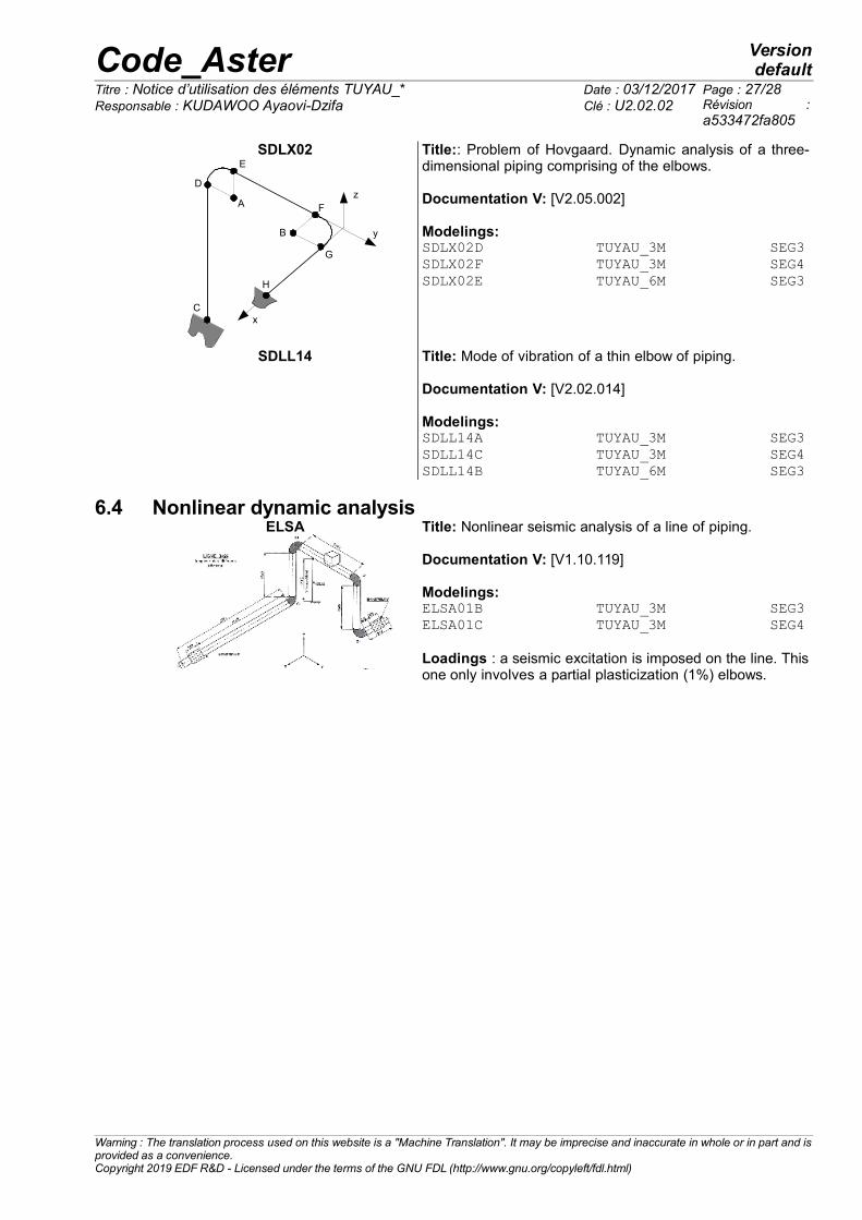
Title:: Problem of Hovgaard. Dynamic analysis of a three-dimensional piping comprising of the elbows. Documentation V: [V2.05.002]
Modelings:SDLX02D TUYAU_3M SEG3SDLX02F TUYAU_3M SEG4SDLX02E TUYAU_6M SEG3
SDLL14 Title: Mode of vibration of a thin elbow of piping.
Documentation V: [V2.02.014]
Modelings:SDLL14A TUYAU_3M SEG3SDLL14C TUYAU_3M SEG4SDLL14B TUYAU_6M SEG3
6.4 Nonlinear dynamic analysisELSA
Title: Nonlinear seismic analysis of a line of piping.
Documentation V: [V1.10.119]
Modelings:ELSA01B TUYAU_3M SEG3ELSA01C TUYAU_3M SEG4
Loadings : a seismic excitation is imposed on the line. Thisone only involves a partial plasticization (1%) elbows.
Warning : The translation process used on this website is a "Machine Translation". It may be imprecise and inaccurate in whole or in part and isprovided as a convenience.Copyright 2019 EDF R&D - Licensed under the terms of the GNU FDL (http://www.gnu.org/copyleft/fdl.html)

Code_Aster Versiondefault
Titre : Notice d’utilisation des éléments TUYAU_* Date : 03/12/2017 Page : 28/28Responsable : KUDAWOO Ayaovi-Dzifa Clé : U2.02.02 Révision :
a533472fa805
7 Bibliographical references1. Finite elements of right pipe and curve with ovalization, swelling and warping in elastoplasticity,
Documentation Code_Aster, Manuel de Référence [R3.08.06]
2. Modelings TUYAU_3M and TUYAU_6M, Documentation Code_Aster, Instruction manual [U3.11.06]
3. ELSA01 - nonlinear seismic Analysis of a line of piping, Documentation Code_Aster, Manuel deValidation [V1.10.119]
4. HSNV100 - Thermoplasticity in simple traction, Documentation Code_Aster, Manuel de Validation[V7.22.100]
5. SDLL14 - Modes of vibration of an elbow of piping thin, Documentation Code_Aster, Manuel deValidation [V2.02.014]
6. SDLX02 – Piping: Problem of Hovgaard. Spectral analysis, Documentation Code_Aster, Manuel deValidation [V2.05.002]
7. SSNL106 - Beam elastoplastic in traction and pure inflection, Documentation Code_Aster, Manuel deValidation [V6.02.106]
8. SSLX101 - Pipe right modelled in hulls and beams, Documentation Code_Aster, Manuel de Validation[V3.05.101]
9. SSLX102 - Piping bent in inflection, Documentation Code_Aster, Manuel de Validation [V3.05.102]
10. SSNL503 - Elastoplastic ruin of a thin bent pipe, Documentation Code_Aster, Manuel de Validation[V6.02.503]
11. ZZZZ112 - Cylinder under variable pressure. Validation of LIRE_PLEXUS, Documentation Code_Aster,Manuel de Validation [V1.01.112]
12. P. MASSIN, J.M. PROIX, F. WAECKEL, E. CHAMPAIN: Modeling of the behavior not - linear materialof the pipings right and bent in statics and dynamics, Note HI - 74/99/013/A, EDF/MTI, 1999.
13. E. CHAMPAIN, Project CACIP: Validation of the developments relating to the taking into account ofplasticity in the pipes, HP-52/99/029/B, EDF/AMV, 2000.
Warning : The translation process used on this website is a "Machine Translation". It may be imprecise and inaccurate in whole or in part and isprovided as a convenience.Copyright 2019 EDF R&D - Licensed under the terms of the GNU FDL (http://www.gnu.org/copyleft/fdl.html)


![NIS-ElementsBR...2000/04/11 · Note Clickingthe[Uninstall]commanddeletesallinstalledfilesfromdisk,andremovestheNIS-Elements BRprogramgroupfromtheStartmenuaswellasitremovesthedesktopicon](https://img.pdfslide.net/doc/110x75/604a993eafb3676fc658ef8b/nis-20000411-note-clickingtheuninstallcommanddeletesallinstalledfilesfromdiskandremovesthenis-elements.jpg)


![Producteur des articles de laboratoire en caoutchouc par ... · Tuyaux à gaz [Tuyau à gaz de sécurité] [Tuyau à gaz pour brûleur à gaz] [Allume-gaz "Clipper"] € Tuyau à](https://img.pdfslide.net/doc/110x75/5e1950bcb67d2129c317c413/producteur-des-articles-de-laboratoire-en-caoutchouc-par-tuyaux-gaz-tuyau.jpg)


![Note of use of the elements plates, hulls, [] · Note of use of the elements plates, hulls, grids and membranes Summary: This document is a note of use for modelings plates, hulls,](https://img.pdfslide.net/doc/110x75/5f0211f47e708231d4026c95/note-of-use-of-the-elements-plates-hulls-note-of-use-of-the-elements-plates.jpg)