Embed Size (px)
Citation preview
1
Mixing Notes: Chapter 19(Part 1) Robert P. Hesketh
Mixing in the process industry: • Chemicals • Food • Pharmaceuticals • Paper • Polymers • Minerals • Environmental
Chemical Industry:
• Paints and Coatings • Synthetic Rubbers and Resin • Sealants and Adhesives • Food, Juice, Oils, and Candy • Catalysts • Acids • Biofuels, Ethanol • Pharmaceuticals
Importance of Mixing1 Chemical Industry: Up to $10 Billion lost because of poor mixing Pharmaceutical Industry:
1. Low yield $100 million 2. Poor scale-up $500 million 3. Lost opportunity form poor mixing – very large number
Typical Mixing Problems adopted from R. K. Grenville: Single-phase: Determine the time required to blend miscible liquids to obtain a uniform mixture
1. Reduce concentration gradients 2. The miscible fluids may have different physical properties 3. A chemical reaction may be present
Two-phase: Liquid-liquid Determine the power required to from 0.01 mm droplets of oil in water.
1. Generate surface area for mass transfer / reaction 2. Stable dispersion (emulsion) may be final product
2
Two-phase: Gas-liquid Determine the rate of mass transfer that can be obtained from sparging gas into liquid within a mechanically agitated tank. Assume geometry, power and fluid properties are given.
1. The gas phase will from small bubbles with a high surface area per unit volume of gas. 2. The purpose of the high surface area maybe to give high mass transfer rates and
ultimately high reaction rates in the liquid phase. 3. Another purpose maybe to form a stable dispersion (foam) may be final product.
Two-phase: Solid-liquid Determine the minimum impeller speed that will just suspend all of the particles in the tank. Given the diameter and physical properties of the particle and fluid, tank geometry and power.
1. Dissolving / Precipitation / Crystallization 2. Catalyst particles. 3. High solids loading - pastes.
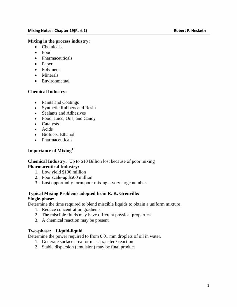
Three-phase: Determine the reaction rate within a liquid in which the catalyst particles are solids and one of the reactants is a gas that dissolves into the liquid to react with a second reactant. Given reaction rate, power, particle and fluid properties, particle diameter, tank geometry. Mixing Definition: Mixing is the reduction of inhomogeneity in order to achieve a desired process result. Inhomogeneity: concentration, phase, temperature. Process results: increase mass and/or heat transfer, reaction rate, or product properties. Typical Tank Dimensions
Figure 1: Definition of Tank Dimensions
3
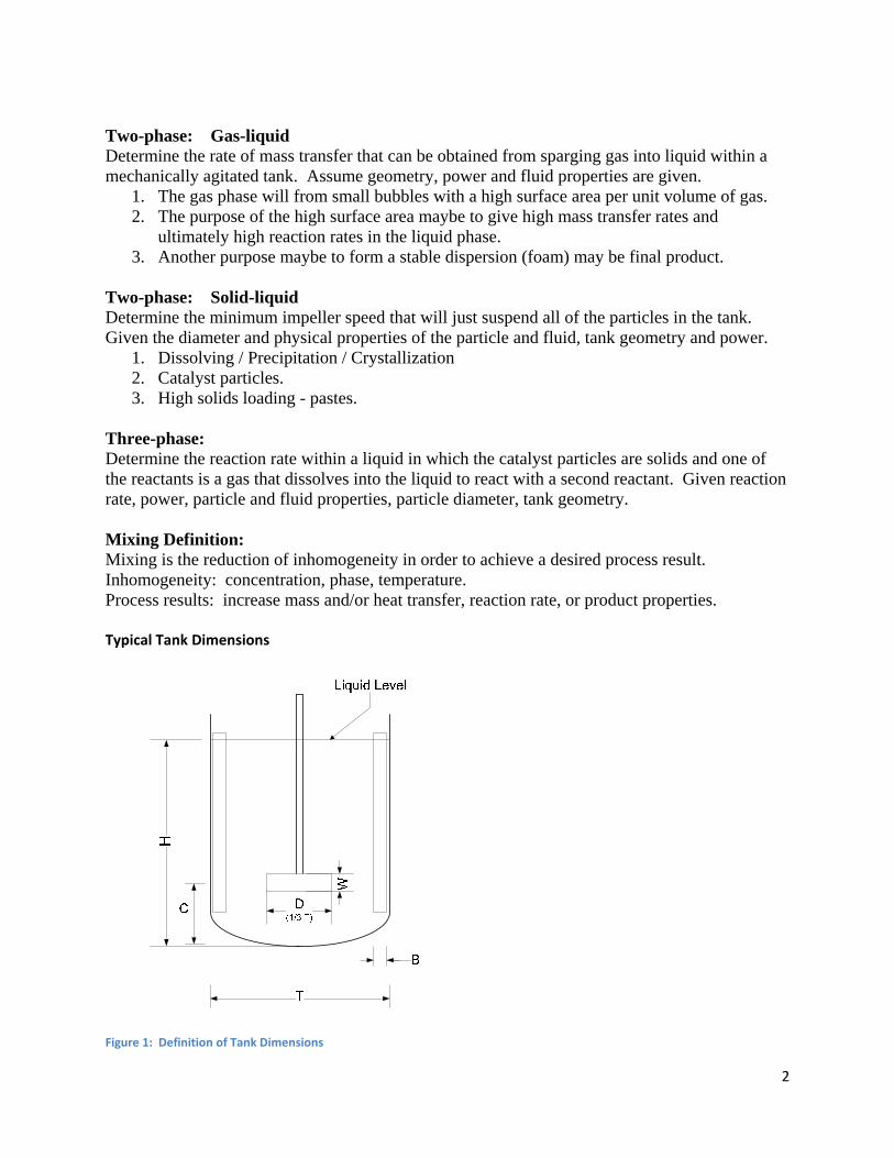
Importance of Baffles: See video from Visual Mixing2
Types of Tanks with mixers
Figure 2: Alternative Mixing Configurations3
4
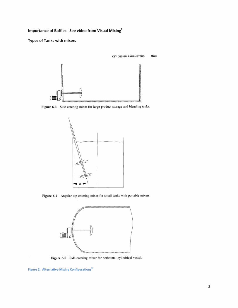
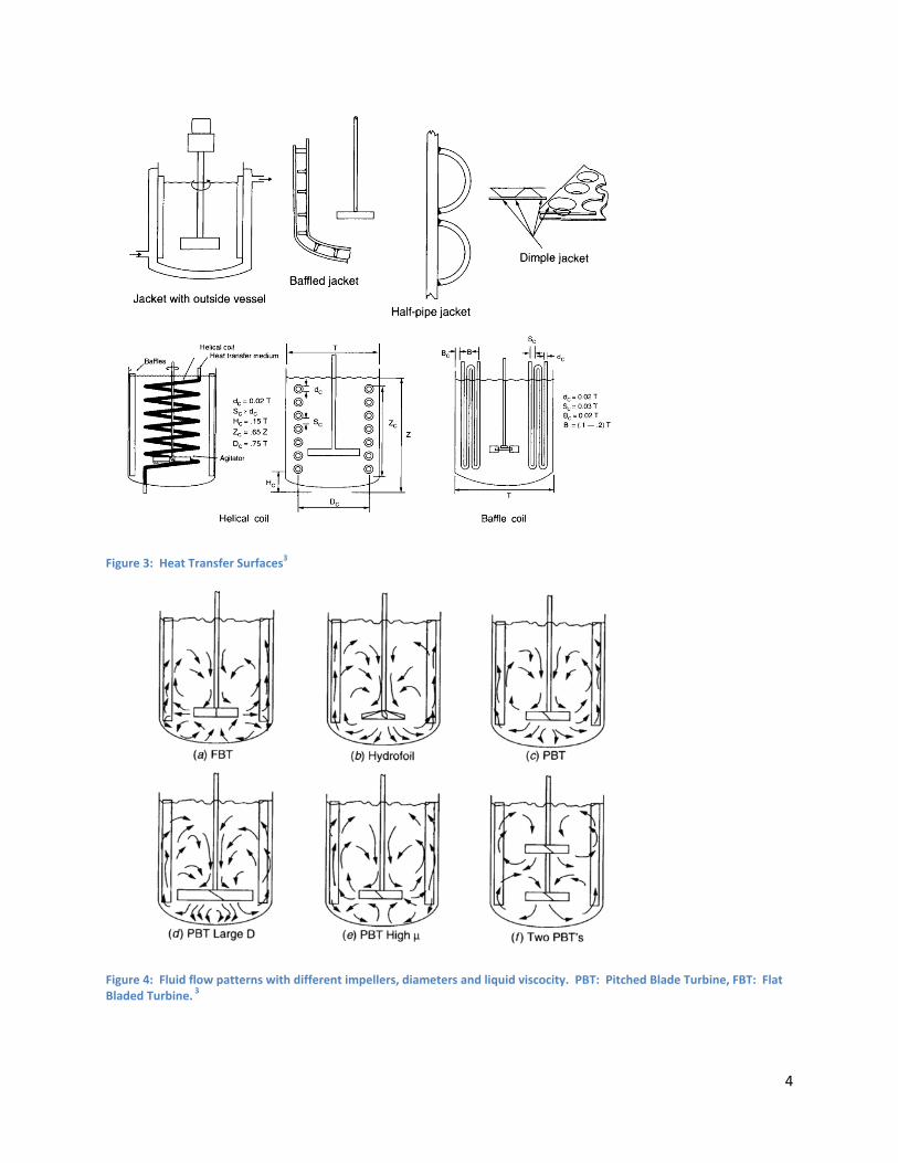
Figure 3: Heat Transfer Surfaces3
Figure 4: Fluid flow patterns with different impellers, diameters and liquid viscocity. PBT: Pitched Blade Turbine, FBT: Flat Bladed Turbine. 3

5
Show Axial Flow CFD simulation from the Visual Mixing CD
Figure 5: Flow patterns for a side ‐ entering Propeller Mixer3
Figure 6: Axial Flow Impellers3
Figure 7: Radial Flow Impellers3
6
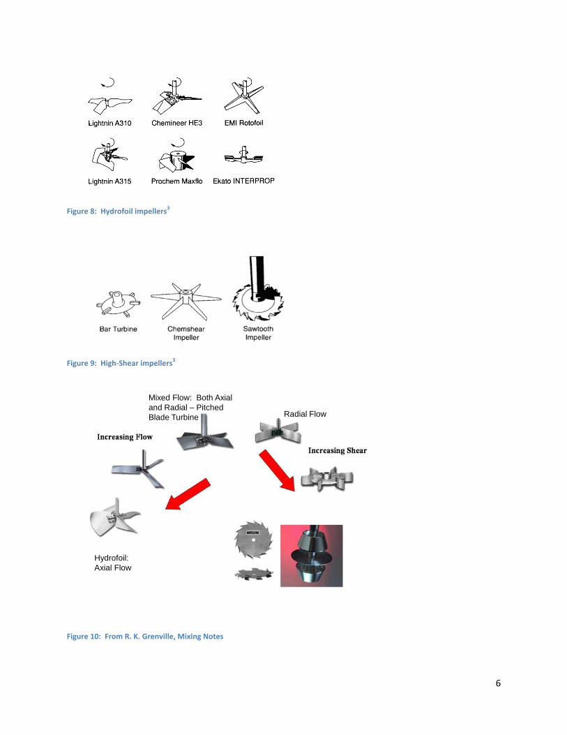
Figure 8: Hydrofoil impellers3
Figure 9: High‐Shear impellers3
Mixed Flow: Both Axial and Radial – Pitched Blade Turbine Radial Flow
Hydrofoil: Axial Flow
Figure 10: From R. K. Grenville, Mixing Notes
7
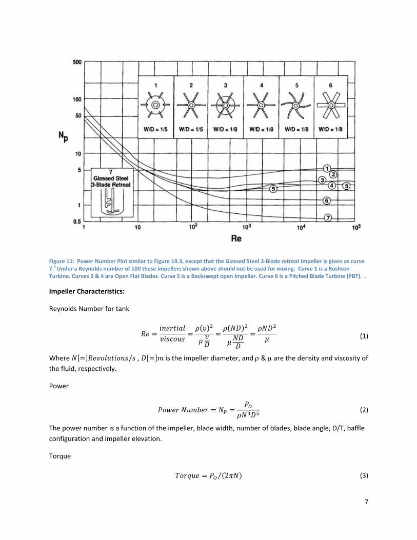
Figure 11: Power Number Plot similar to Figure 19.3, except that the Glassed Steel 3‐Blade retreat Impeller is given as curve 7.1 Under a Reynolds number of 100 these impellers shown above should not be used for mixing. Curve 1 is a Rushton Turbine. Curves 2 & 4 are Open Flat Blades. Curve 5 is a Backswept open Impeller. Curve 6 is a Pitched Blade Turbine (PBT). .
Impeller Characteristics:
Reynolds Number for tank
(1)
Where / , is the impeller diameter, and ρ & μ are the density and viscosity of the fluid, respectively.
Power
(2)
The power number is a function of the impeller, blade width, number of blades, blade angle, D/T, baffle configuration and impeller elevation.
Torque
2⁄ (3)
8
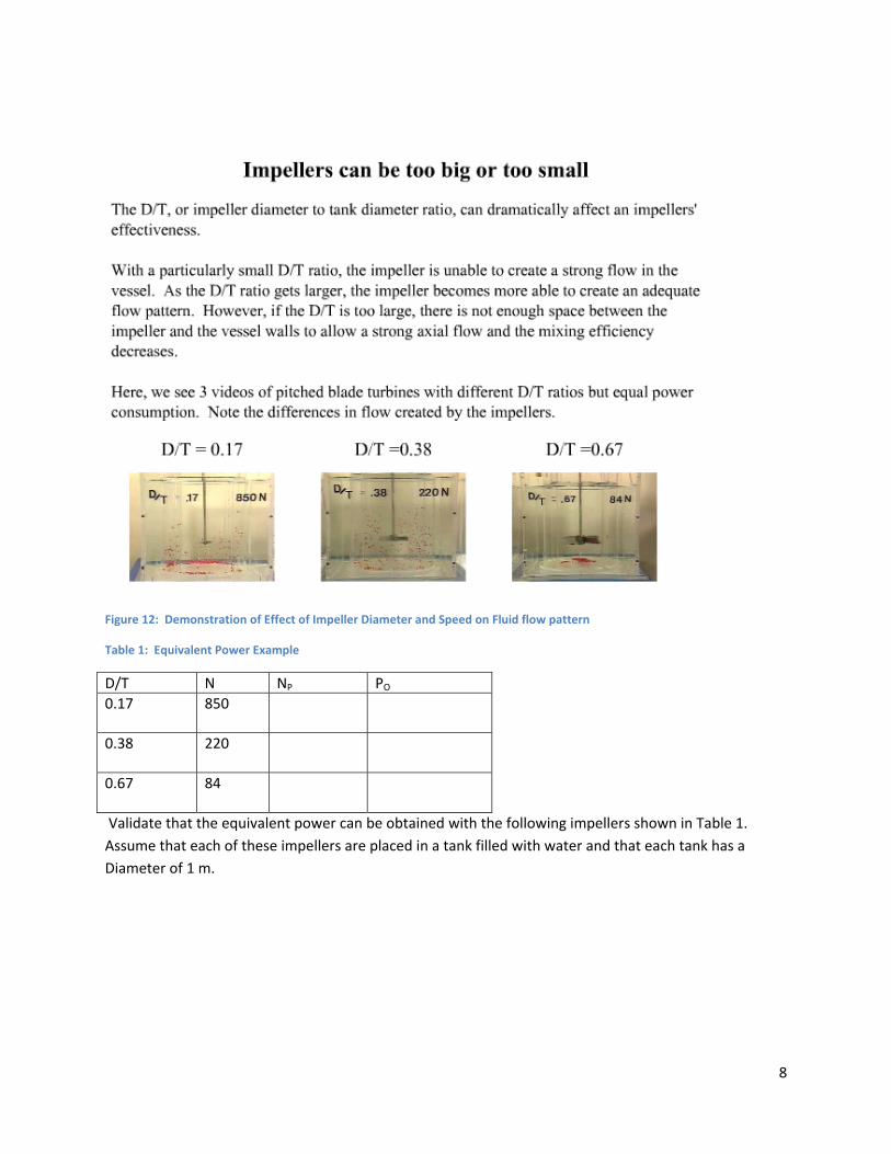
Figure 12: Demonstration of Effect of Impeller Diameter and Speed on Fluid flow pattern
Table 1: Equivalent Power Example
D/T N NP PO 0.17 850
0.38 220
0.67 84
Validate that the equivalent power can be obtained with the following impellers shown in Table 1. Assume that each of these impellers are placed in a tank filled with water and that each tank has a Diameter of 1 m.

9
Figure 13: Comparison of 3 impellers at a low solids loading
Table 2: Equivalent Power Example
Impeller Type NP D/T N PO Rushton 0.23 420
Pitched Blade Turbine (PBT) 0.31 420
A310 0.42 420
1 Paul, E. D. V. A. Atiemo-Obeng, and S. M. Kresta, “Introduction of the Handbook of Industrial Mixing”, Wiley, 2004. 2 Visual Mixing CD by S. Kresta and K. Boyle included with the text by Paul, E. D. V. A. Atiemo-Obeng, and S. M. Kresta, “Handbook of Industrial Mixing”, Wiley, 2004 3 Hemrajani, R. R., G. B. Tatterson, “Mechanically Stirred Vessels,” Chapter 6 of Paul, E. D. V. A. Atiemo-Obeng, and S. M. Kresta, “Introduction of the Handbook of Industrial Mixing”, Wiley, 2004