Embed Size (px)
Citation preview
ME1105 - Engineering Drawing and Design
Contents:
1 The design process and the role of the design model.
1.1 The design process1.2 The design model1.3 Types of design model
2 Representing the design model - Engineering Drawing.
2.1 Projections2.2 Creating Orthographic Projection drawings2.3 Drawing conventions2.4 Sections2.5 Dimensions2.6 Tolerances, limits and fits2.7 Assemblies
1 The design process and the role of the design model.
1.1 The design process:
Almost everything around us has been created by, or is influenced by, engineers:
Buildings, vehicles, roads, railways, food growing and processing, books, medical care,recreation, etc.
All of these have either been concieved and created from scratch or have evolved fromexisting ideas. Either way, an engineering design process will have been followed, inone form or another. The Design as a generic tool module provides an interesting acomprehensive introduction to engineering and design, so a detailed discussion of thedesign process will not be inclided here.
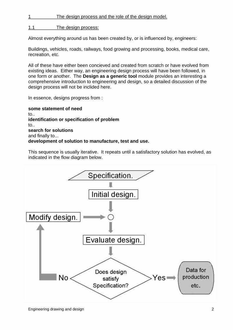
In essence, designs progress from :
some statement of needto..identification or specification of problemto..search for solutionsand finally to...development of solution to manufacture, test and use.
This sequence is usually iterative. It repeats until a satisfactory solution has evolved, asindicated in the flow diagram below.
Engineering drawing and design 2
Engineering drawing & design 3
1.2 The design model.
The concept of the designer working with a model of a design is fundamental to thedesign process.
The design model is a representation of the design. This model could be anything froma few ideas in the designers head, through to rough sketches and notes, calculations,sets of detailed formal engineering drawings, computer generated 3D representations,physical prototypes, etc.
The design model would be used by the designer to record and develop ideas and toprovide a basis to evaluate the design.
Larger design projects are undertaken by more than one engineer. Design models areused to communicate and demonstrate ideas between all those concerned with theproduct design, development, manufacture and use.
A designer needs to have the skills to generate and work with this model in order tocommunicate ideas and develop a design.
1.3 Types of design model.
Designers use a variety of different models, depending on what property of the design isto be considered and for whom the information is destined.
Typically a designer may model:
� Function� Structure� Form� Material properties, surface conditions
All of these areas probably encompass a large portion of the degree syllabus. Withinthis modulke we will concern ourselves primarily with form, i.e. the shape of parts orcomponents and how they fit together.
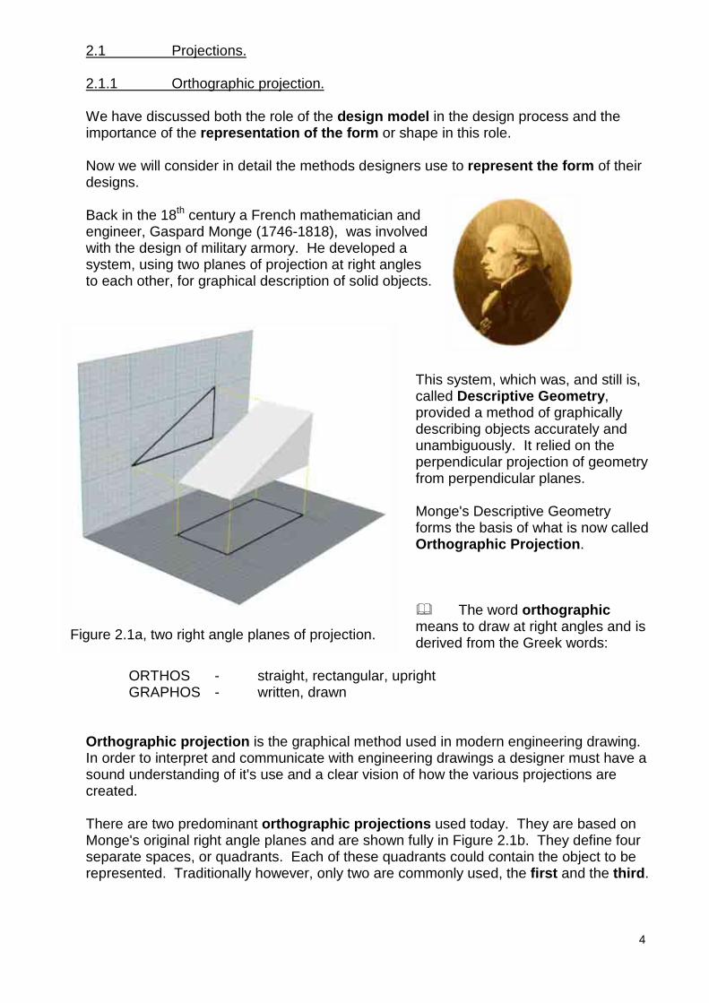
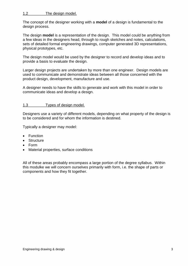
Figure 2.1a, two right angle planes of projection.
2.1 Projections.
2.1.1 Orthographic projection.
We have discussed both the role of the design model in the design process and theimportance of the representation of the form or shape in this role.
Now we will consider in detail the methods designers use to represent the form of theirdesigns.
Back in the 18th century a French mathematician andengineer, Gaspard Monge (1746-1818), was involvedwith the design of military armory. He developed asystem, using two planes of projection at right anglesto each other, for graphical description of solid objects.
This calleprovidescunamperpefrom
MongformsOrth
� meanderiv
ORTHOS - straight, rectangular, uprightGRAPHOS - written, drawn
Orthographic projection is the graphical method used inIn order to interpret and communicate with engineering drsound understanding of it's use and a clear vision of howcreated.
There are two predominant orthographic projections usMonge's original right angle planes and are shown fully inseparate spaces, or quadrants. Each of these quadrantsrepresented. Traditionally however, only two are commo
4
system, which was, and still is,d Descriptive Geometry,ded a method of graphicallyribing objects accurately andbiguously. It relied on thendicular projection of geometryperpendicular planes.
e's Descriptive Geometry the basis of what is now called
ographic Projection.
The word orthographics to draw at right angles and is
ed from the Greek words:
modern engineering drawing.awings a designer must have a
the various projections are
ed today. They are based on Figure 2.1b. They define four could contain the object to benly used, the first and the third.
5
Projections created with the object placed in the first quadrant are said to be in FirstAngle projection, and likewise, projections created with the object placed in the thirdquadrant are said to be in Third Angle projection.
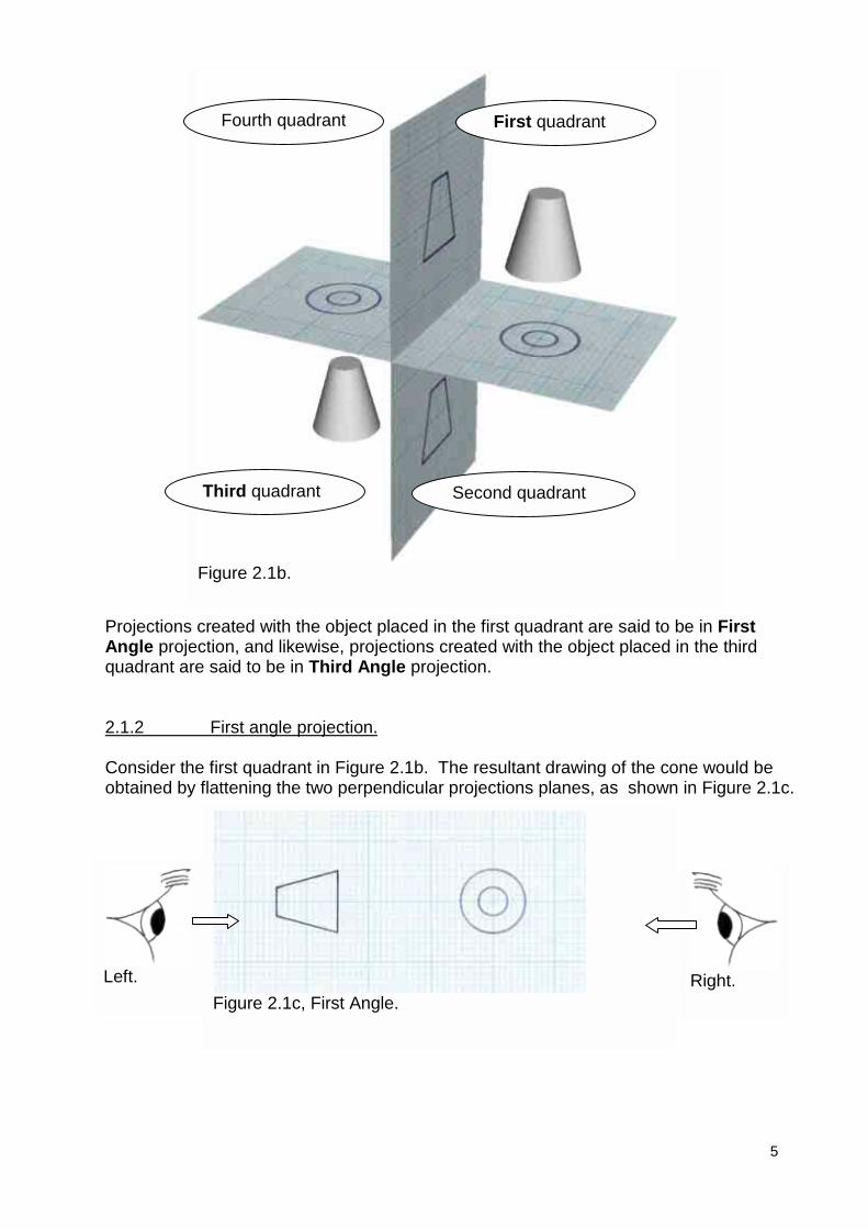
2.1.2 First angle projection.
Consider the first quadrant in Figure 2.1b. The resultant drawing of the cone would beobtained by flattening the two perpendicular projections planes, as shown in Figure 2.1c.
Figure 2.1b.
First quadrantFourth quadrant
Third quadrant Second quadrant
Figure 2.1c, First Angle.Left. Right.
6
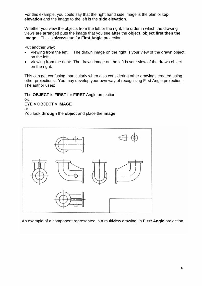
For this example, you could say that the right hand side image is the plan or topelevation and the image to the left is the side elevation.
Whether you view the objects from the left or the right, the order in which the drawingviews are arranged puts the image that you see after the object, object first then theimage. This is always true for First Angle projection.
Put another way:� Viewing from the left: The drawn image on the right is your view of the drawn object
on the left.� Viewing from the right: The drawn image on the left is your view of the drawn object
on the right.
This can get confusing, particularly when also considering other drawings created usingother projections. You may develop your own way of recognising First Angle projection.The author uses:
The OBJECT is FIRST for FIRST Angle projection.or...EYE > OBJECT > IMAGEor...You look through the object and place the image
An example of a component represented in a multiview drawing, in First Angle projection.
Engineering Drawing & CAD Page 5 of 7
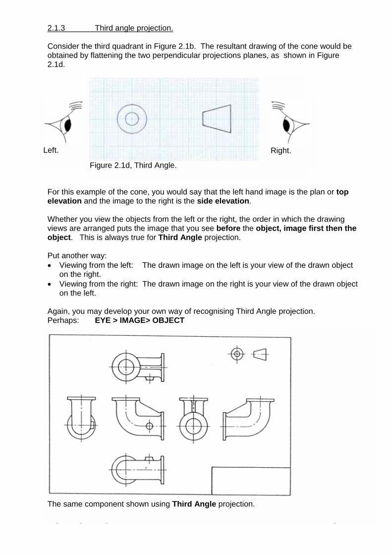
2.1.3 Third angle projection.
Consider the third quadrant in Figure 2.1b. The resultant drawing of the cone would beobtained by flattening the two perpendicular projections planes, as shown in Figure2.1d.
For this example of the cone, you would say that the left hand image is the plan or topelevation and the image to the right is the side elevation.
Whether you view the objects from the left or the right, the order in which the drawingviews are arranged puts the image that you see before the object, image first then theobject. This is always true for Third Angle projection.
Put another way:� Viewing from the left: The drawn image on the left is your view of the drawn object
on the right.� Viewing from the right: The drawn image on the right is your view of the drawn object
on the left.
Again, you may develop your own way of recognising Third Angle projection. Perhaps: EYE > IMAGE> OBJECT
Figure 2.1d, Third Angle.
Left. Right.
The same component shown using Third Angle projection.
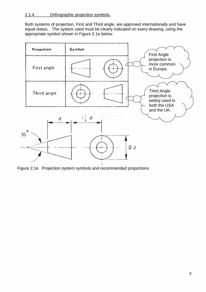
2.1.4 Orthographic projection symbols.
Both systems of projection, First and Third angle, are approved internationally and haveequal status. The system used must be clearly indicated on every drawing, using theappropriate symbol shown in Figure 2.1e below.
Figure 2.1e. Projection system symbols and recommended proportions.
First Angleprojection ismore commonin Europe.
Third Angleprojection iswidely used inboth the USAand the UK.
8
9
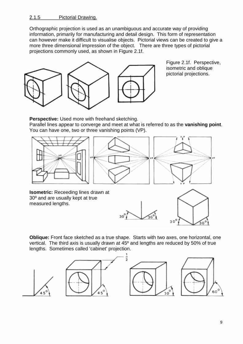
2.1.5 Pictorial Drawing.
Orthographic projection is used as an unambiguous and accurate way of providinginformation, primarily for manufacturing and detail design. This form of representationcan however make it difficult to visualise objects. Pictorial views can be created to give amore three dimensional impression of the object. There are three types of pictorialprojections commonly used, as shown in Figure 2.1f.
Figure 2.1f. Perspective,isometric and obliquepictorial projections.
Perspective: Used more with freehand sketching.Parallel lines appear to converge and meet at what is referred to as the vanishing point.You can have one, two or three vanishing points (VP).
Isometric: Receeding lines drawn at30º and are usually kept at truemeasured lengths.
Oblique: Front face sketched as a true shape. Starts with two axes, one horizontal, onevertical. The third axis is usually drawn at 45º and lengths are reduced by 50% of truelengths. Sometimes called 'cabinet' projection.
10
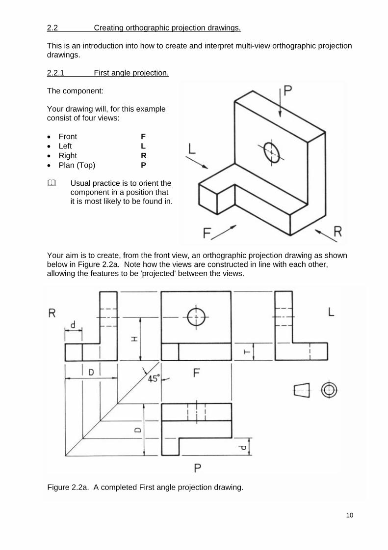
2.2 Creating orthographic projection drawings.
This is an introduction into how to create and interpret multi-view orthographic projectiondrawings.
2.2.1 First angle projection.
The component:
Your drawing will, for this exampleconsist of four views:
� Front F� Left L� Right R� Plan (Top) P
� Usual practice is to orient thecomponent in a position thatit is most likely to be found in.
Your aim is to create, from the front view, an orthographic projection drawing as shownbelow in Figure 2.2a. Note how the views are constructed in line with each other,allowing the features to be 'projected' between the views.
Figure 2.2a. A completed First angle projection drawing.
11
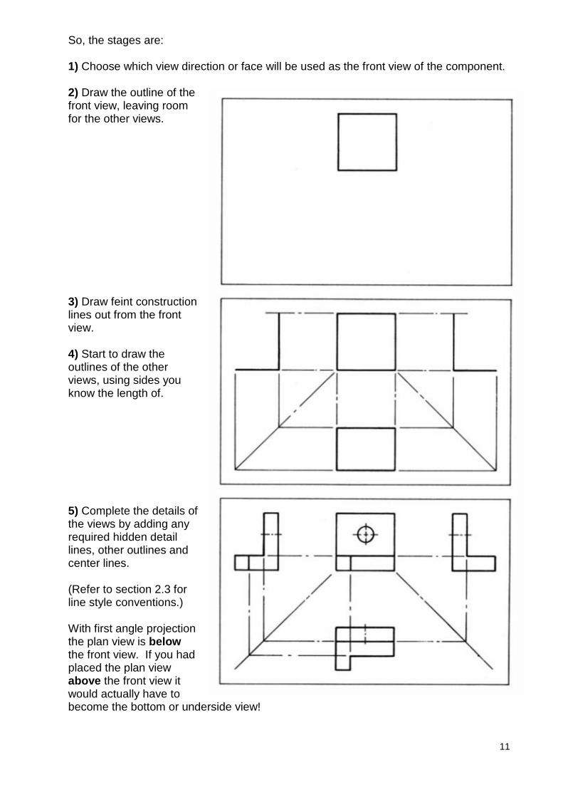
So, the stages are:
1) Choose which view direction or face will be used as the front view of the component.
2) Draw the outline of thefront view, leaving roomfor the other views.
3) Draw feint constructionlines out from the frontview.
4) Start to draw theoutlines of the otherviews, using sides youknow the length of.
5) Complete the details ofthe views by adding anyrequired hidden detaillines, other outlines andcenter lines.
(Refer to section 2.3 forline style conventions.)
With first angle projectionthe plan view is belowthe front view. If you hadplaced the plan viewabove the front view itwould actually have tobecome the bottom or underside view!
12
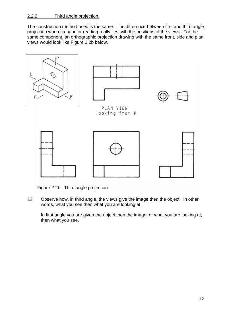
2.2.2 Third angle projection.
The construction method used is the same. The difference between first and third angleprojection when creating or reading really lies with the positions of the views. For thesame component, an orthographic projection drawing with the same front, side and planviews would look like Figure 2.2b below.
� Observe how, in third angle, the views give the image then the object. In otherwords, what you see then what you are looking at.
In first angle you are given the object then the image, or what you are looking at,then what you see.
Figure 2.2b. Third angle projection.
Engineering drawing & design 13
2.3 Drawing conventions.
2.3.1 Introduction.
In order for anyone to be able to understand exactly what a drawing represents, sets ofprecise rules and conventions have to be followed, much like a language. These rulesare usually referred to as Standards.
When a designer works to a set of Standards they must be familiar with the precisemeaning of the various line styles, abbreviations, drawing simplifications andterminology. This section introduces you to some of the common universal conventions.
Standards are developed both privately by companies and by internationally recognisedinstitutions.
� Two such international standards are:
British Standard Institution: BS 8888 (Superceded BS 308)
American National Standards Institute: Y14 series
The conventions referenced in these notes generally comply with BS 8888.
Engineering drawing & desig
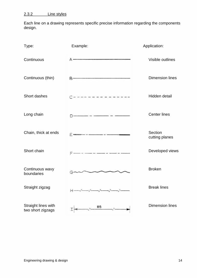
2.3.2 Line styles
Each line on a drawing represents specific precise information regarding the componentsdesign.
Type: Example: Application:
Continuous
Continuous (thin)
Short dashes
Long chain
Chain, thick at ends
Short chain
Continuous wavyboundaries
Straight zigzag
Straight lines with two short zigzags
n 14
Visible outlines
Dimension lines
Hidden detail
Center lines
Section cutting planes
Developed views
Broken
Break lines
Dimension lines
Engineering drawing & design 15
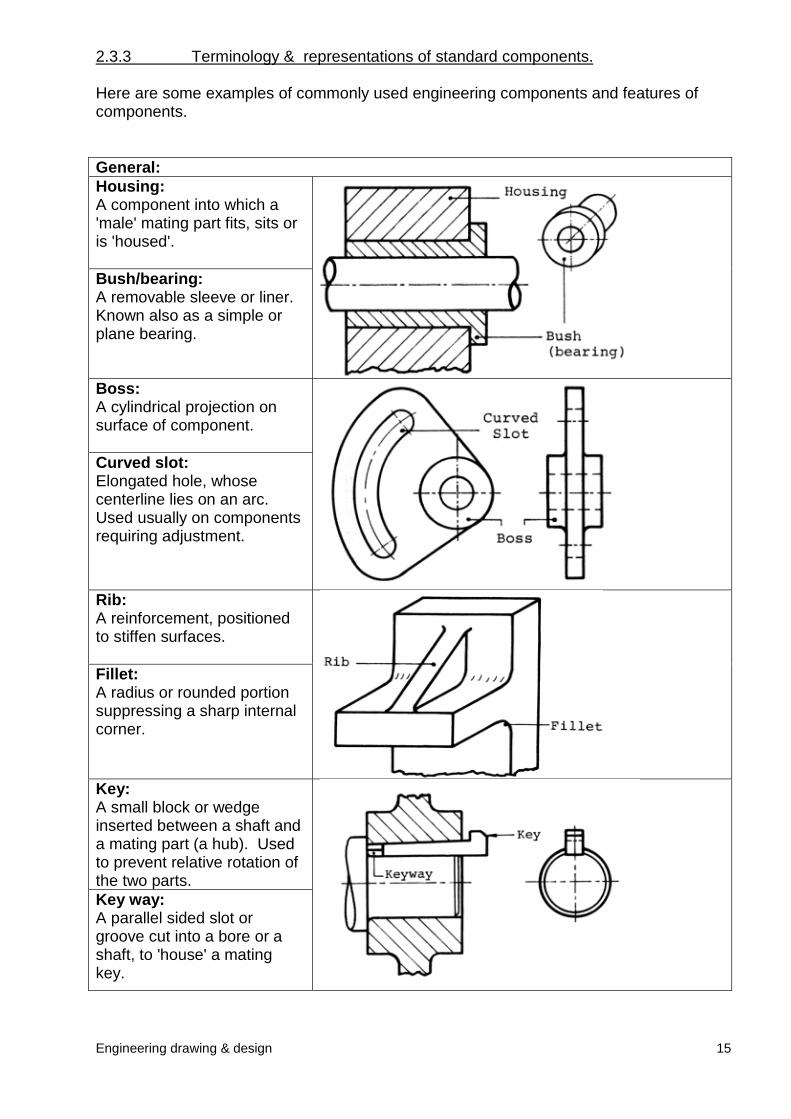
2.3.3 Terminology & representations of standard components.
Here are some examples of commonly used engineering components and features ofcomponents.
General:Housing:A component into which a'male' mating part fits, sits oris 'housed'.
Bush/bearing:A removable sleeve or liner.Known also as a simple orplane bearing.
Boss:A cylindrical projection onsurface of component.
Curved slot:Elongated hole, whosecenterline lies on an arc.Used usually on componentsrequiring adjustment.
Rib:A reinforcement, positionedto stiffen surfaces.
Fillet:A radius or rounded portionsuppressing a sharp internalcorner.
Key:A small block or wedgeinserted between a shaft anda mating part (a hub). Usedto prevent relative rotation ofthe two parts.Key way:A parallel sided slot orgroove cut into a bore or ashaft, to 'house' a matingkey.
Engineering drawing & design 16
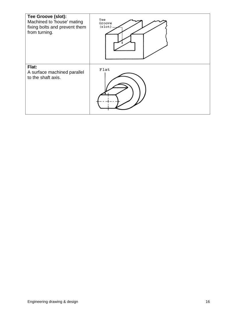
Tee Groove (slot):Machined to 'house' matingfixing bolts and prevent themfrom turning.
Flat:A surface machined parallelto the shaft axis.
Engineering drawing & design 17
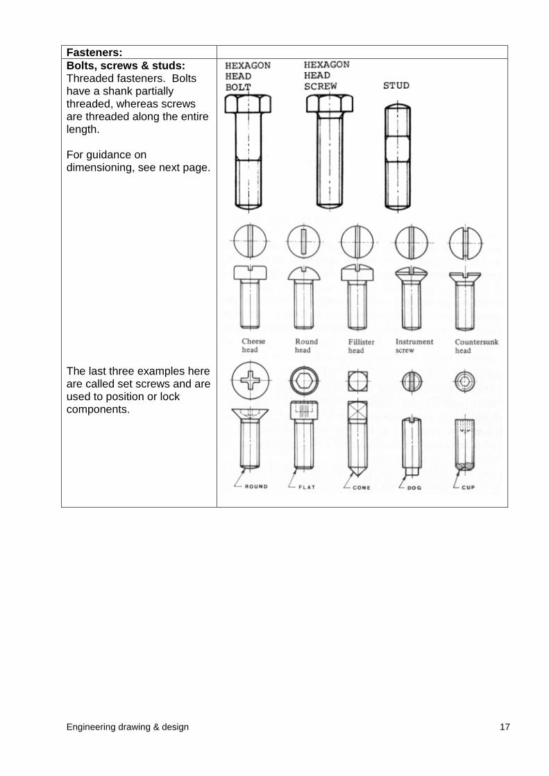
Fasteners:Bolts, screws & studs:Threaded fasteners. Boltshave a shank partiallythreaded, whereas screwsare threaded along the entirelength.
For guidance ondimensioning, see next page.
The last three examples hereare called set screws and areused to position or lockcomponents.
Engineering drawing & design 18
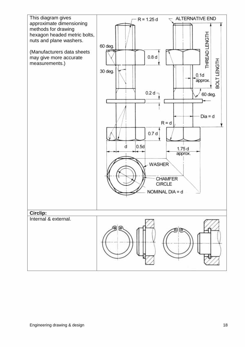
This diagram givesapproximate dimensioningmethods for drawinghexagon headed metric bolts,nuts and plane washers.
(Manufacturers data sheetsmay give more accuratemeasurements.)
Circlip:Internal & external.
Engineering drawing & design 19
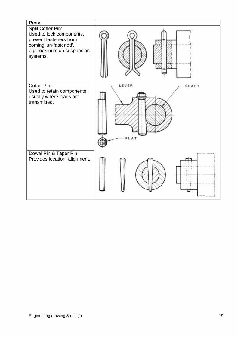
Pins:Split Cotter Pin:Used to lock components,prevent fasteners fromcoming 'un-fastened'.e.g. lock-nuts on suspensionsystems.
Cotter Pin:Used to retain components,usually where loads aretransmitted.
Dowel Pin & Taper Pin:Provides location, alignment.
Engineering drawing & design 20
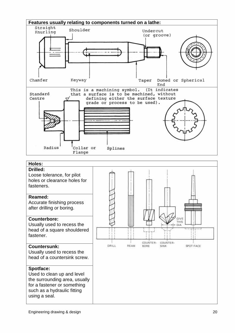
Features usually relating to components turned on a lathe:
Holes:Drilled:Loose tolerance, for pilotholes or clearance holes forfasteners.
Reamed:Accurate finishing processafter drilling or boring.
Counterbore:Usually used to recess thehead of a square shoulderedfastener.
Countersunk:Usually used to recess thehead of a countersink screw.
Spotface:Used to clean up and levelthe surrounding area, usuallyfor a fastener or somethingsuch as a hydraulic fittingusing a seal.
Engineering drawing & design 21
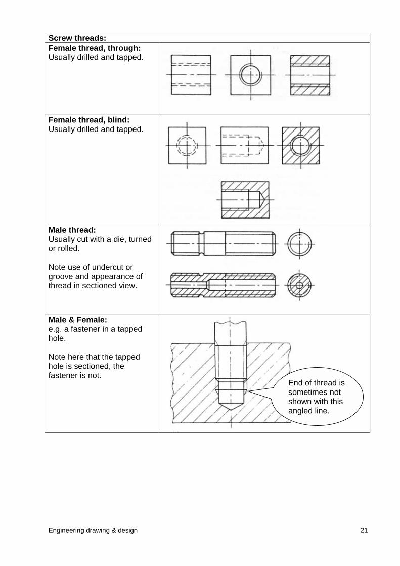
Screw threads:Female thread, through:Usually drilled and tapped.
Female thread, blind:Usually drilled and tapped.
Male thread:Usually cut with a die, turnedor rolled.
Note use of undercut orgroove and appearance ofthread in sectioned view.
Male & Female:e.g. a fastener in a tappedhole.
Note here that the tappedhole is sectioned, thefastener is not.
End of thread issometimes notshown with thisangled line.
Engineering drawing & design 22
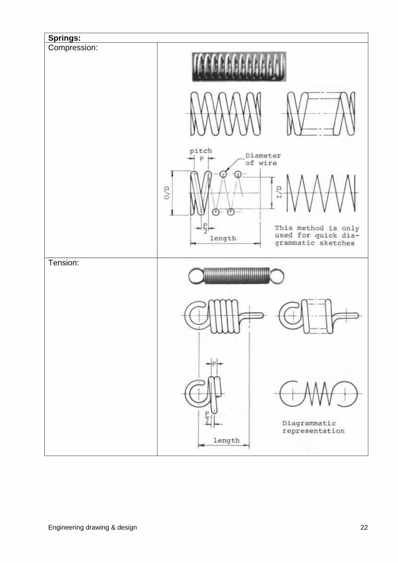
Springs:Compression:
Tension:
Engineering drawing & drawing 23
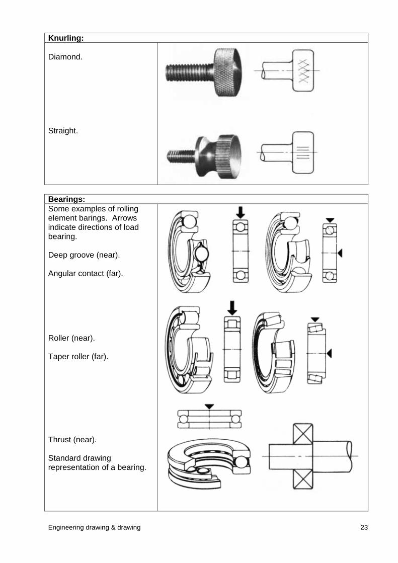
Knurling:
Diamond.
Straight.
Bearings:Some examples of rollingelement barings. Arrowsindicate directions of loadbearing.
Deep groove (near).
Angular contact (far).
Roller (near).
Taper roller (far).
Thrust (near).
Standard drawingrepresentation of a bearing.
Engineering drawing & drawing 24
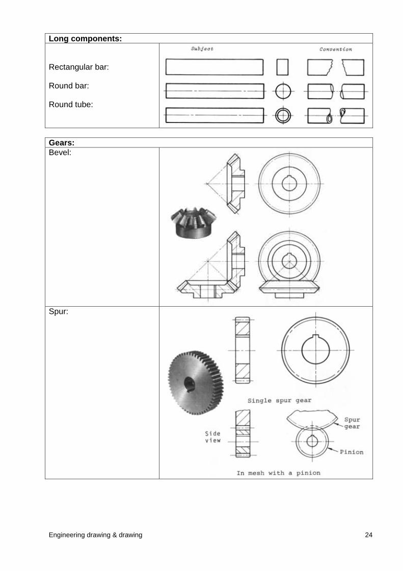
Long components:
Rectangular bar:
Round bar:
Round tube:
Gears:Bevel:
Spur:
Engineering drawing & design 25
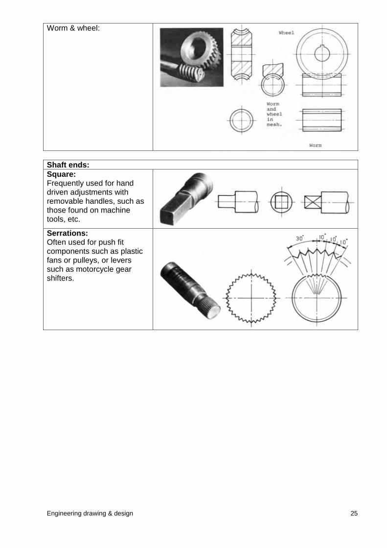
Worm & wheel:
Shaft ends:Square:Frequently used for handdriven adjustments withremovable handles, such asthose found on machinetools, etc.
Serrations:Often used for push fitcomponents such as plasticfans or pulleys, or leverssuch as motorcycle gearshifters.
Engineering drawing & design 26
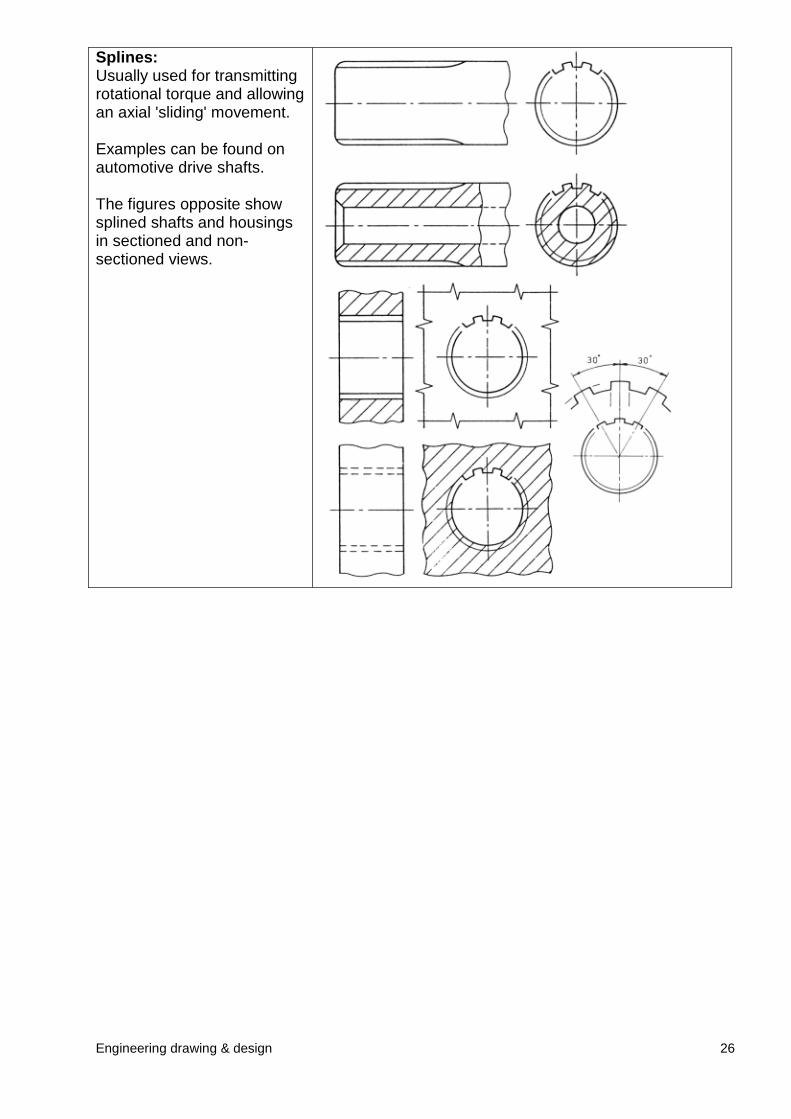
Splines:Usually used for transmittingrotational torque and allowingan axial 'sliding' movement.
Examples can be found onautomotive drive shafts.
The figures opposite showsplined shafts and housingsin sectioned and non-sectioned views.
Engineering drawing & design 27
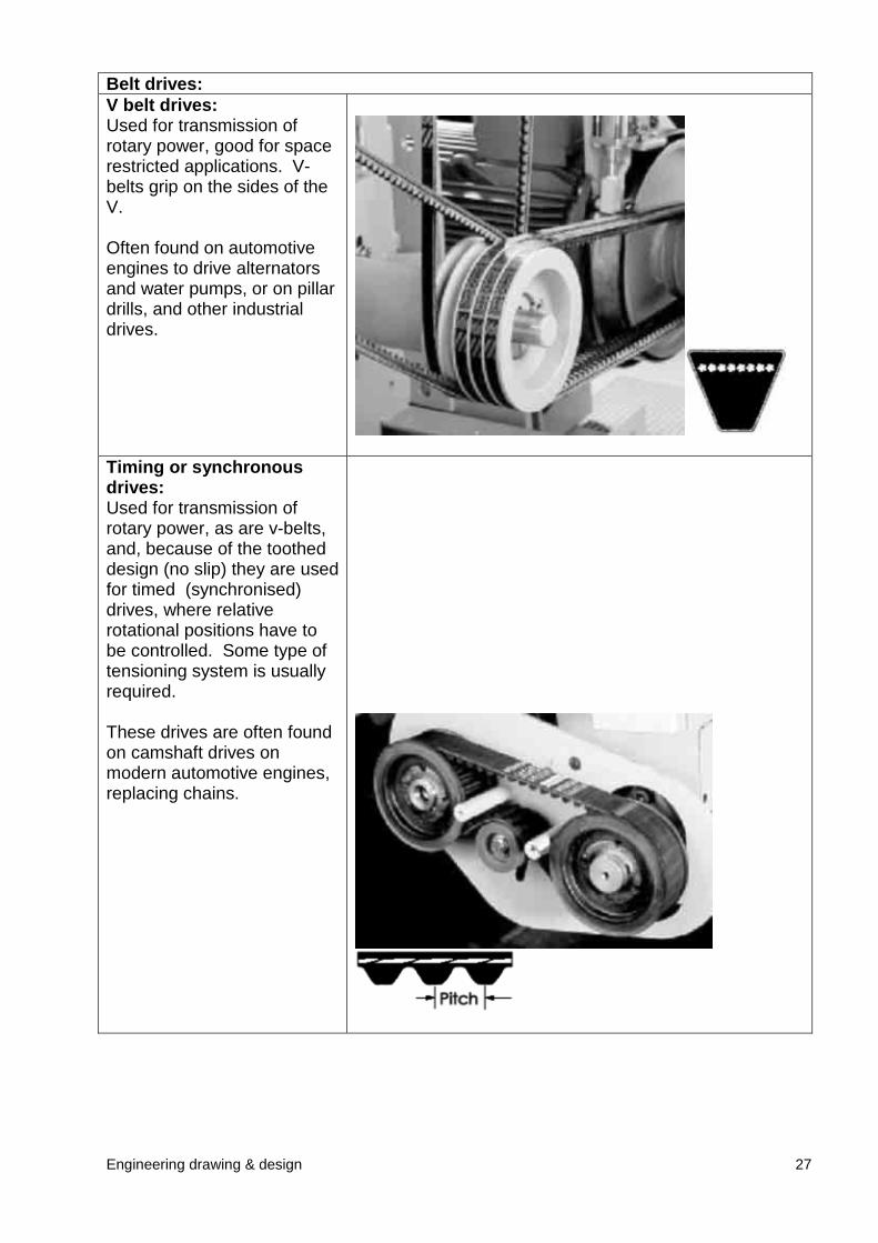
Belt drives:V belt drives:Used for transmission ofrotary power, good for spacerestricted applications. V-belts grip on the sides of theV.
Often found on automotiveengines to drive alternatorsand water pumps, or on pillardrills, and other industrialdrives.
Timing or synchronousdrives:Used for transmission ofrotary power, as are v-belts,and, because of the tootheddesign (no slip) they are usedfor timed (synchronised)drives, where relativerotational positions have tobe controlled. Some type oftensioning system is usuallyrequired.
These drives are often foundon camshaft drives onmodern automotive engines,replacing chains.
Engineering drawing & design 28
2.3.5 Abbreviations of terms frequently used on drawings.
Abbreviations are used on drawings to save time and space. Most of these conform toBS 8888. They are the same singular or plural, full stops are only used where word maybe confusing.
A/C Across cornersA/F Across flatsHEX HD Hexagon headASSY AssemblyCRS CentersCL Center lineCHAM ChamferCH HD Cheese headCSK CountersunkCBORE CounterboreCYL Cylinder or cylindricalDIA Diameter (in a note)Ø Diameter (preceding a dimension)R Radius (preceding a dimension, capital only)RAD Radius (in a note)DRG DrawingFIG. FigureLH Left handLG LongMATL MaterialNO. NumberPATT NO. Pattern numberPCD Pitch circle diameterI/D Inside diameterO/D Outside diameterRH Right handRD HD Round headSCR ScrewedSPEC SpecificationSPHERE SphericalSFACE SpotfaceSQ Square (in a note)TYP Typical or typicallyTHK Thick� Square (preceding a dimension)STD StandardUCUT UndercutM/CD Machinedmm MillimeterNTS Not to scaleRPM Revolutions per minuteSWG Standard wire gaugeTPI Teeth per inch
Engineering drawing & design 29
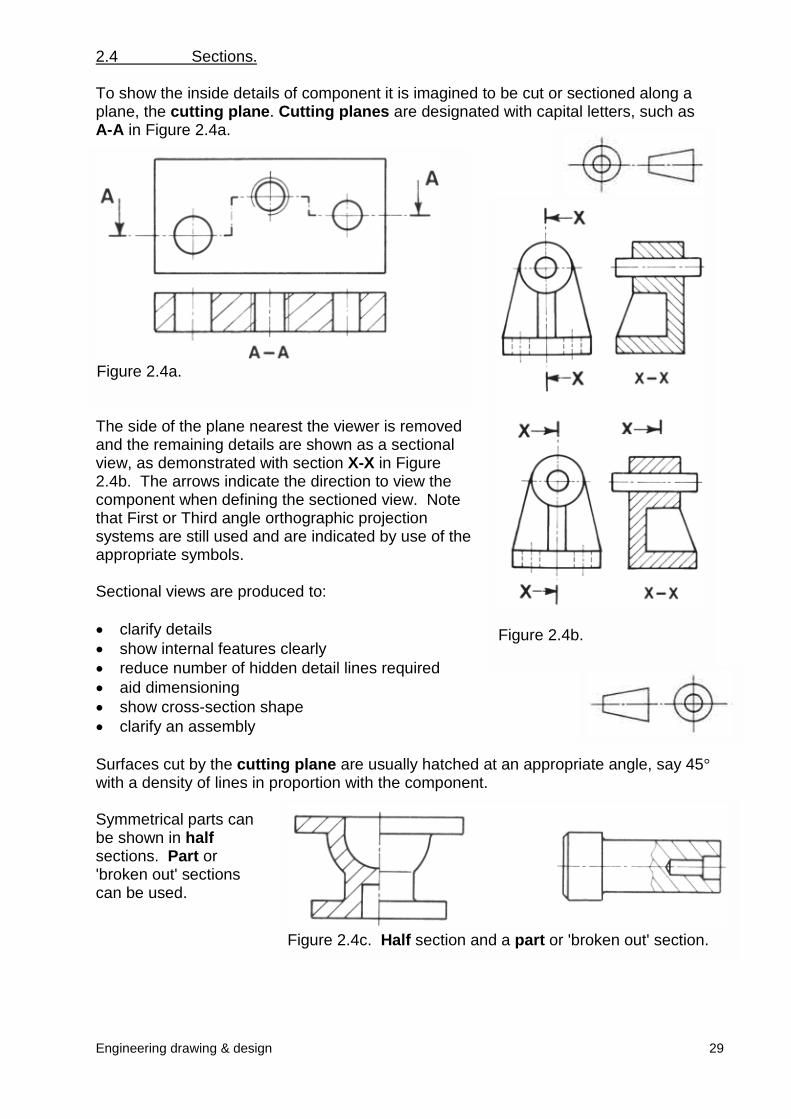
Figure 2.4a.
Figure 2.4c. Half section and a part or 'broken out' section.
Figure 2.4b.
2.4 Sections.
To show the inside details of component it is imagined to be cut or sectioned along aplane, the cutting plane. Cutting planes are designated with capital letters, such asA-A in Figure 2.4a.
The side of the plane nearest the viewer is removedand the remaining details are shown as a sectionalview, as demonstrated with section X-X in Figure2.4b. The arrows indicate the direction to view thecomponent when defining the sectioned view. Notethat First or Third angle orthographic projectionsystems are still used and are indicated by use of theappropriate symbols.
Sectional views are produced to:
� clarify details� show internal features clearly� reduce number of hidden detail lines required� aid dimensioning� show cross-section shape� clarify an assembly
Surfaces cut by the cutting plane are usually hatched at an appropriate angle, say 45�with a density of lines in proportion with the component.
Symmetrical parts canbe shown in halfsections. Part or'broken out' sectionscan be used.
Engineering drawing & design
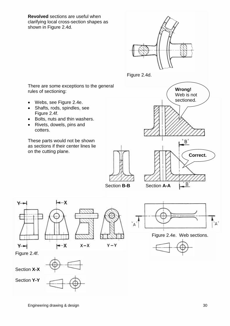
Figure 2.4f.
Section X-X
Section Y-Y
Figure 2.4d.
Revolved sections are useful whenclarifying local cross-section shapes asshown in Figure 2.4d.
There are some exceptions to the generalrules of sectioning:
� Webs, see Figure 2.4e.� Shafts, rods, spindles, see
Figure 2.4f.� Bolts, nuts and thin washers.� Rivets, dowels, pins and
cotters.
These parts would not be shownas sections if their center lines lieon the cutting plane.
Wrong!Web is not
sectioned.30
Section B-B Section A-A
Figure 2.4e. Web sections.
Correct.
Engineering drawing & design
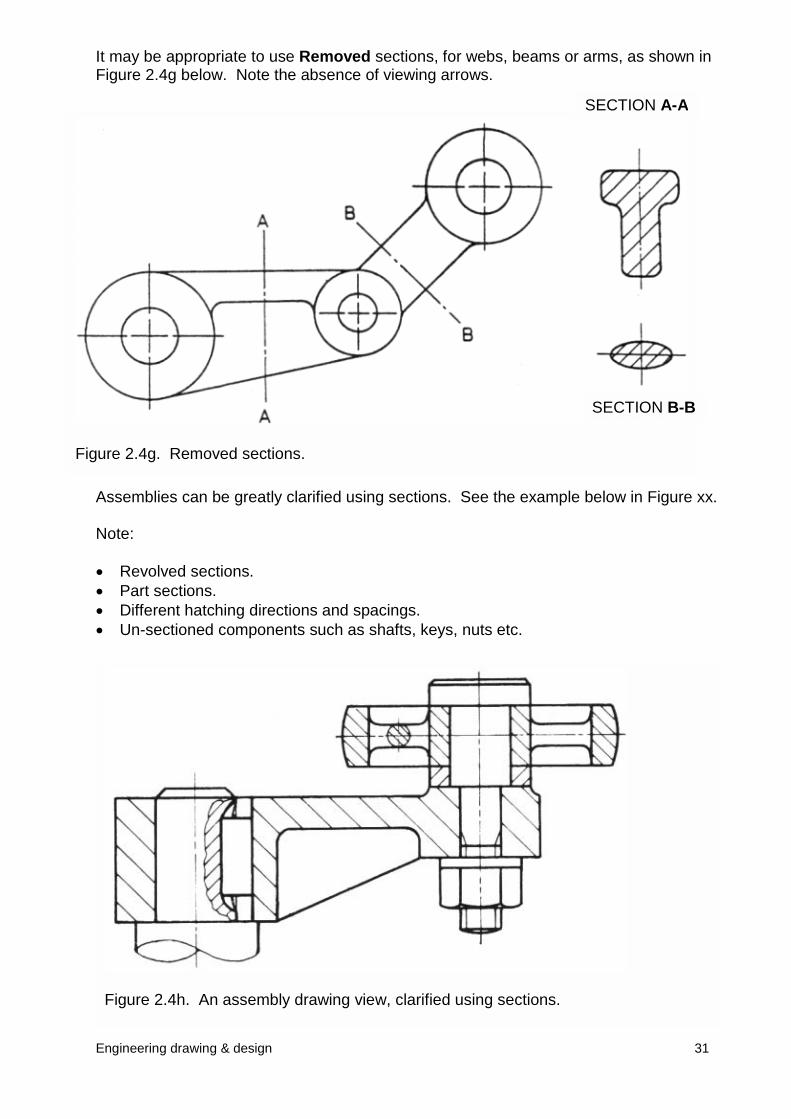
It may be appropriate to use Removed sections, for webs, beams or arms, as shown inFigure 2.4g below. Note the absence of viewing arrows.
Assemblies can be greatly clarified using sections. See the example
Note:
� Revolved sections.� Part sections.� Different hatching directions and spacings.� Un-sectioned components such as shafts, keys, nuts etc.
Figure 2.4h. An assembly drawing view, clarified using sections.
Figure 2.4g. Removed sections.
A
SECTION A-SECTION B-B
31
below in Figure xx.
2.5 Dimensions.
A drawing from which a component is to be manufactured must communicate designinformation by:
� Describing the form or shape of the component by using orthographic and sometimespictorial views.
� Giving actual sizes by dimensioning.
� Giving information about any special manufacturing processes required.
The design engineer should have a good understanding of projection methods,dimensioning methods and the manufacturing methods to be used.
This section introduces some basic guidelines and examples to help explain the generalrules of dimensioning, based on BS 8888.
2.5.1 General rules.
� Dimensions should be placed on drawings so that they may be easily read.
� The drawing must include the minimum number of dimensions necessary tomanufacture.
� A dimension should not be stated more than once unless it aids communication.
� It should not be necessary for the operator manufacturing the component to have tocalculate any dimensions.
2.5.2 Types of dimension.
Types of dimensioning can be broadly classified as:
� Size dimensions. Used to describe heights, widths, diameters, etc.
� Location dimensions. Used to place various features of a component relative toeach other, such as a hole centre line to a reference surface.
� Mating dimensions. Used for parts that fit together requiring a certain degree ofaccuracy.
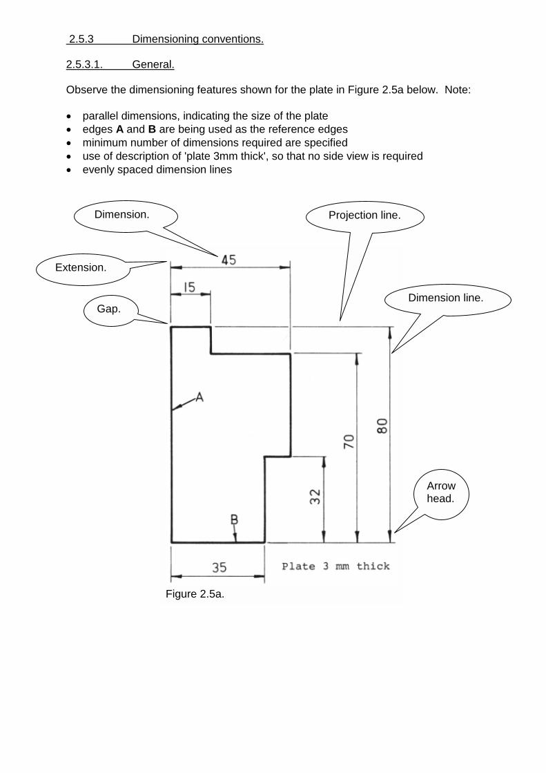
Figure 2.5a.
2.5.3 Dimensioning conventions.
2.5.3.1. General.
Observe the dimensioning features shown for the plate in Figure 2.5a below. Note:
� parallel dimensions, indicating the size of the plate� edges A and B are being used as the reference edges� minimum number of dimensions required are specified� use of description of 'plate 3mm thick', so that no side view is required� evenly spaced dimension lines
Dimension line.
Projection line.
Arrowhead.
Dimension.
Gap.
Extension.
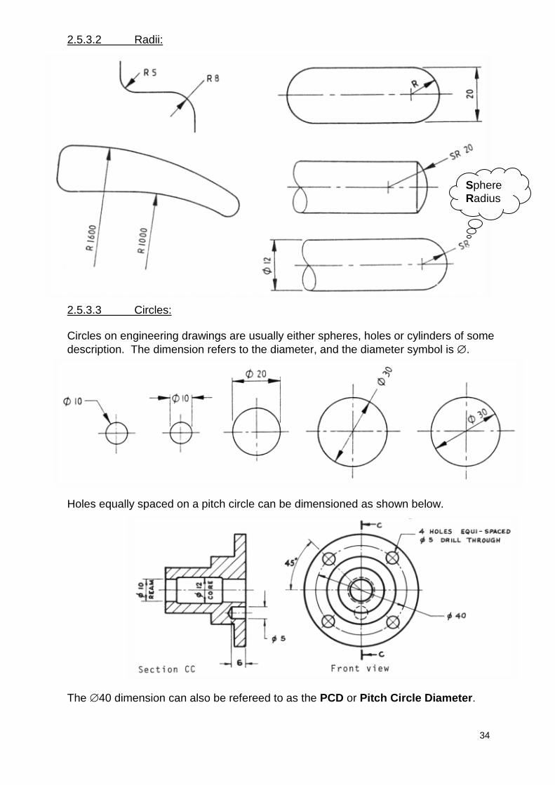
2.5.3.2 Radii:
2.5.3.3 Circles:
Circles on engineering drawings are usually either spheres, holes or cylinders of somedescription. The dimension refers to the diameter, and the diameter symbol is �.
SphereRadius
34
Holes equally spaced on a pitch circle can be dimensioned as shown below.
The �40 dimension can also be refereed to as the PCD or Pitch Circle Diameter.
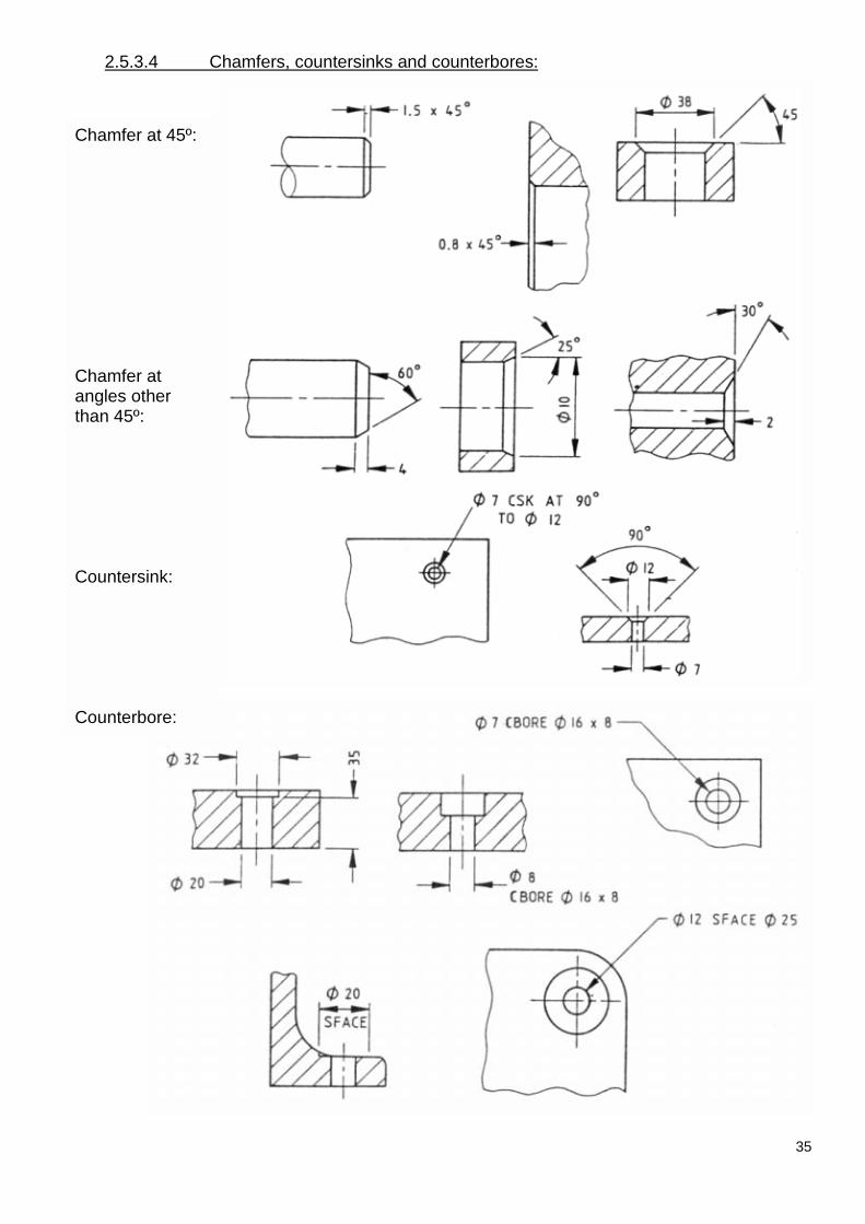
2.5.3.4 Chamfers, countersinks and counterbores:
Chamfer at 45º:
Chamfer atangles otherthan 45º:
Countersink:
Counterbore:
35
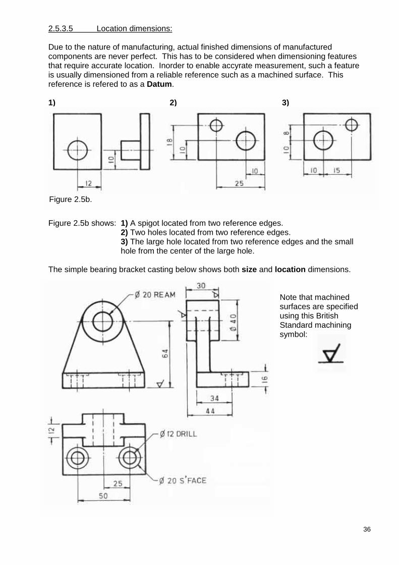
2.5.3.5 Location dimensions:
Due to the nature of manufacturing, actual finished dimensions of manufacturedcomponents are never perfect. This has to be considered when dimensioning featuresthat require accurate location. Inorder to enable accyrate measurement, such a featureis usually dimensioned from a reliable reference such as a machined surface. Thisreference is refered to as a Datum.
1) 2) 3)
Figure 2.5b shows: 1) A spigot located from two reference edges.2) Two holes located from two reference edges.3) The large hole located from two reference edges and the smallhole from the center of the large hole.
The simple bearing bracket casting below shows both size and location dimensions.
Note that machinedsurfaces are specifiedusing this BritishStandard machiningsymbol:
Figure 2.5b.
36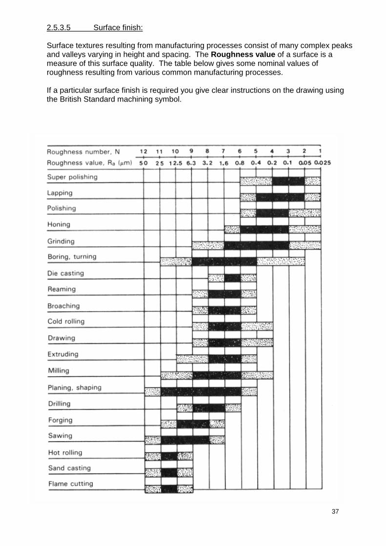
37
2.5.3.5 Surface finish:
Surface textures resulting from manufacturing processes consist of many complex peaksand valleys varying in height and spacing. The Roughness value of a surface is ameasure of this surface quality. The table below gives some nominal values ofroughness resulting from various common manufacturing processes.
If a particular surface finish is required you give clear instructions on the drawing usingthe British Standard machining symbol.
Engineering drawing & design
2.6 Tolerances, limits and fits.
In order to ensure that assemblies function properly their component parts must fittogether in a predictable way. As mentioned in section 2.5, no component can bemanufactured to an exact size, so the designer has to decide on appropriate upper andlower limits for each dimension.
� Accurately toleranced dimensioned features usually take much more time tomanufacture correctly and therefore can increase production costs significantly.Good engineering practise finds the optimum balance between required accuracyfor the function of the component and minimum cost of manufacture.
2.6.1 Dimension tolerances.
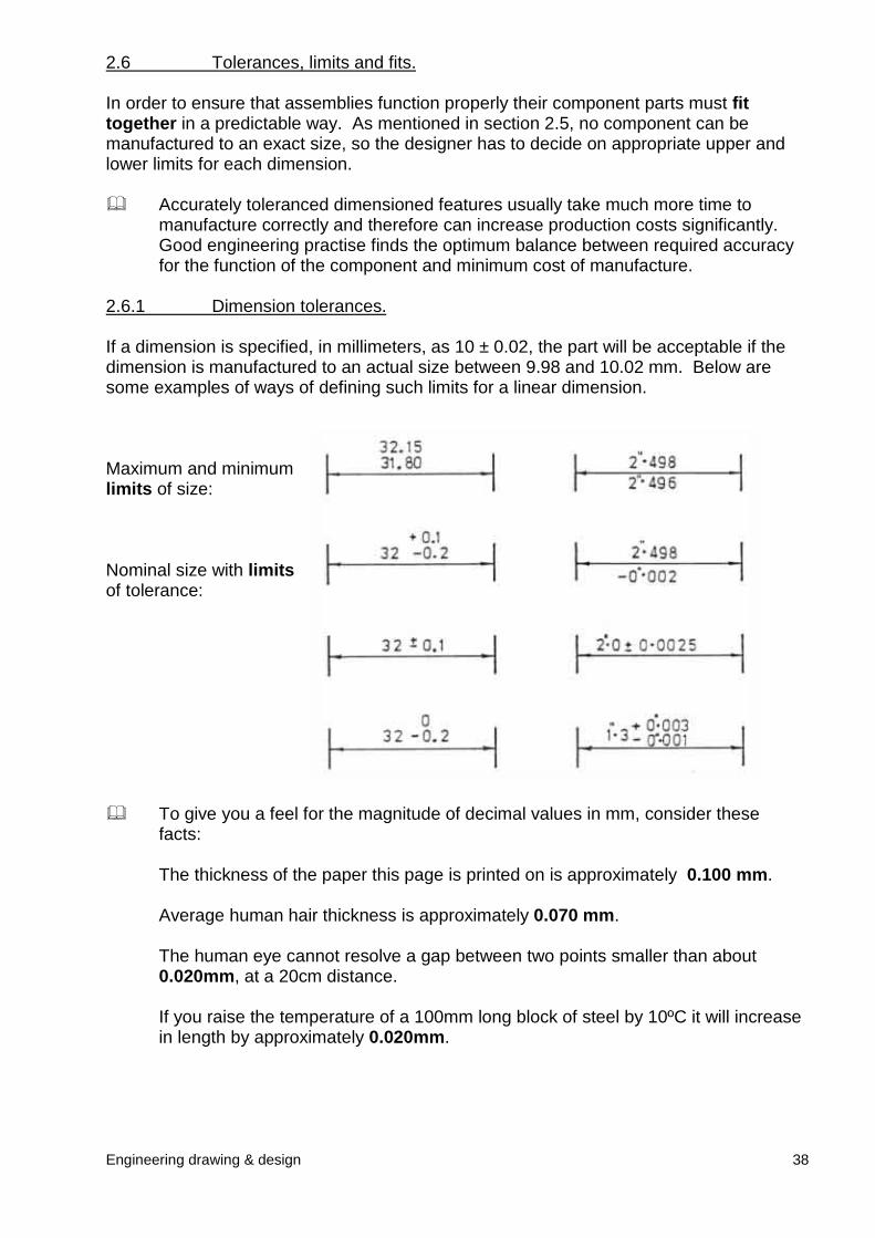
If a dimension is specified, in millimeters, as 10 ± 0.02, the part will be acceptable if thedimension is manufactured to an actual size between 9.98 and 10.02 mm. Below aresome examples of ways of defining such limits for a linear dimension.
Maximum and minimumlimits of size:
Nominal size with limitsof tolerance:
� To give you a feel fofacts:
The thickness of the
Average human hair
The human eye can0.020mm, at a 20cm
If you raise the tempin length by approxim
38
r the magnitude of decimal values in mm, consider these
paper this page is printed on is approximately 0.100 mm.
thickness is approximately 0.070 mm.
not resolve a gap between two points smaller than about distance.
erature of a 100mm long block of steel by 10ºC it will increaseately 0.020mm.
Engineering drawing & design
2.6.2 General tolerancing.
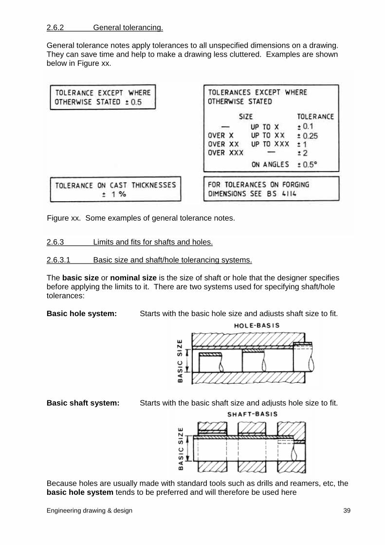
General tolerance notes apply tolerances to all unspecified dimensions on a drawing.They can save time and help to make a drawing less cluttered. Examples are shownbelow in Figure xx.
2.6.3 Limits and fits for shafts and holes.
2.6.3.1 Basic size and shaft/hole tolerancing systems.
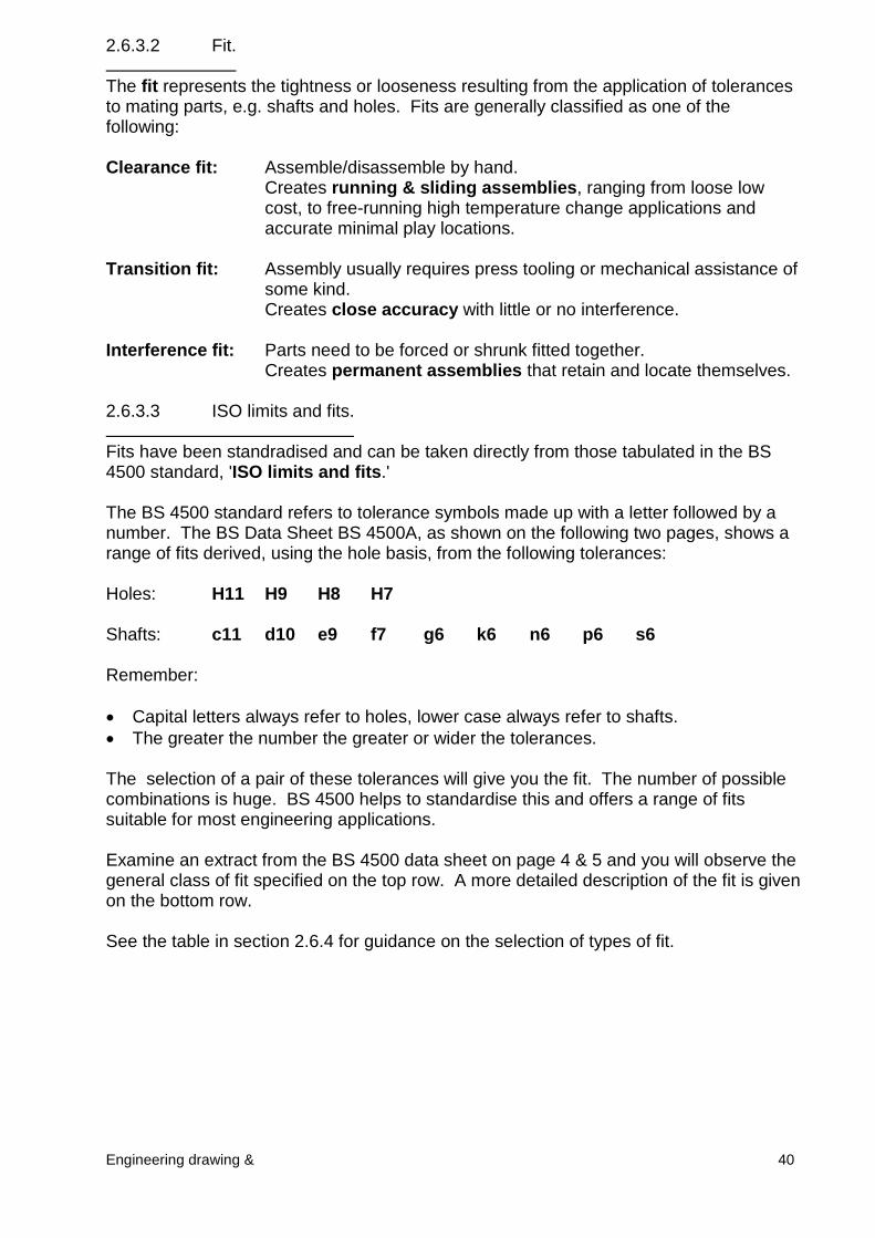
The basic size or nominal size is the size of shaft or hole that the designer specifiesbefore applying the limits to it. There are two systems used for specifying shaft/holetolerances:
Basic hole system: Starts with the basic hole size and adjusts shaft size to fit.
Basic shaft system: Starts with the basic shaft size and adjusts hole size to fit.
Because holes are usually made witbasic hole system tends to be prefe
Figure xx. Some examples of general tolerance notes.
39
h standard tools such as drills and reamers, etc, therred and will therefore be used here
2.6.3.2 Fit.
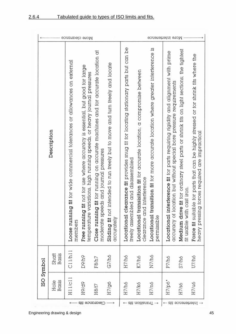
The fit represents the tightness or looseness resulting from the application of tolerancesto mating parts, e.g. shafts and holes. Fits are generally classified as one of thefollowing:
Engineering drawing & 40
Clearance fit: Assemble/disassemble by hand.Creates running & sliding assemblies, ranging from loose lowcost, to free-running high temperature change applications andaccurate minimal play locations.
Transition fit: Assembly usually requires press tooling or mechanical assistance ofsome kind. Creates close accuracy with little or no interference.
Interference fit: Parts need to be forced or shrunk fitted together.Creates permanent assemblies that retain and locate themselves.
2.6.3.3 ISO limits and fits.
Fits have been standradised and can be taken directly from those tabulated in the BS4500 standard, 'ISO limits and fits.'
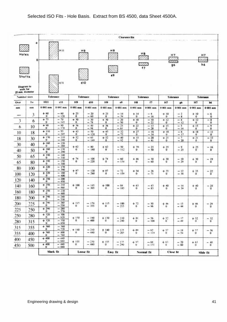
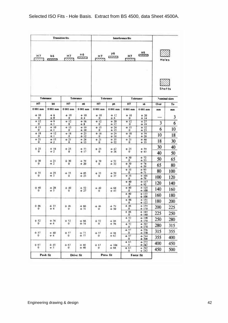
The BS 4500 standard refers to tolerance symbols made up with a letter followed by anumber. The BS Data Sheet BS 4500A, as shown on the following two pages, shows arange of fits derived, using the hole basis, from the following tolerances:
Holes: H11 H9 H8 H7
Shafts: c11 d10 e9 f7 g6 k6 n6 p6 s6
Remember:
� Capital letters always refer to holes, lower case always refer to shafts.� The greater the number the greater or wider the tolerances.
The selection of a pair of these tolerances will give you the fit. The number of possiblecombinations is huge. BS 4500 helps to standardise this and offers a range of fitssuitable for most engineering applications.
Examine an extract from the BS 4500 data sheet on page 4 & 5 and you will observe thegeneral class of fit specified on the top row. A more detailed description of the fit is givenon the bottom row.
See the table in section 2.6.4 for guidance on the selection of types of fit.
Engineering drawing & design 41
Selected ISO Fits - Hole Basis. Extract from BS 4500, data Sheet 4500A.
Engineering drawing & design 42
Selected ISO Fits - Hole Basis. Extract from BS 4500, data Sheet 4500A.
Engineering drawing & design
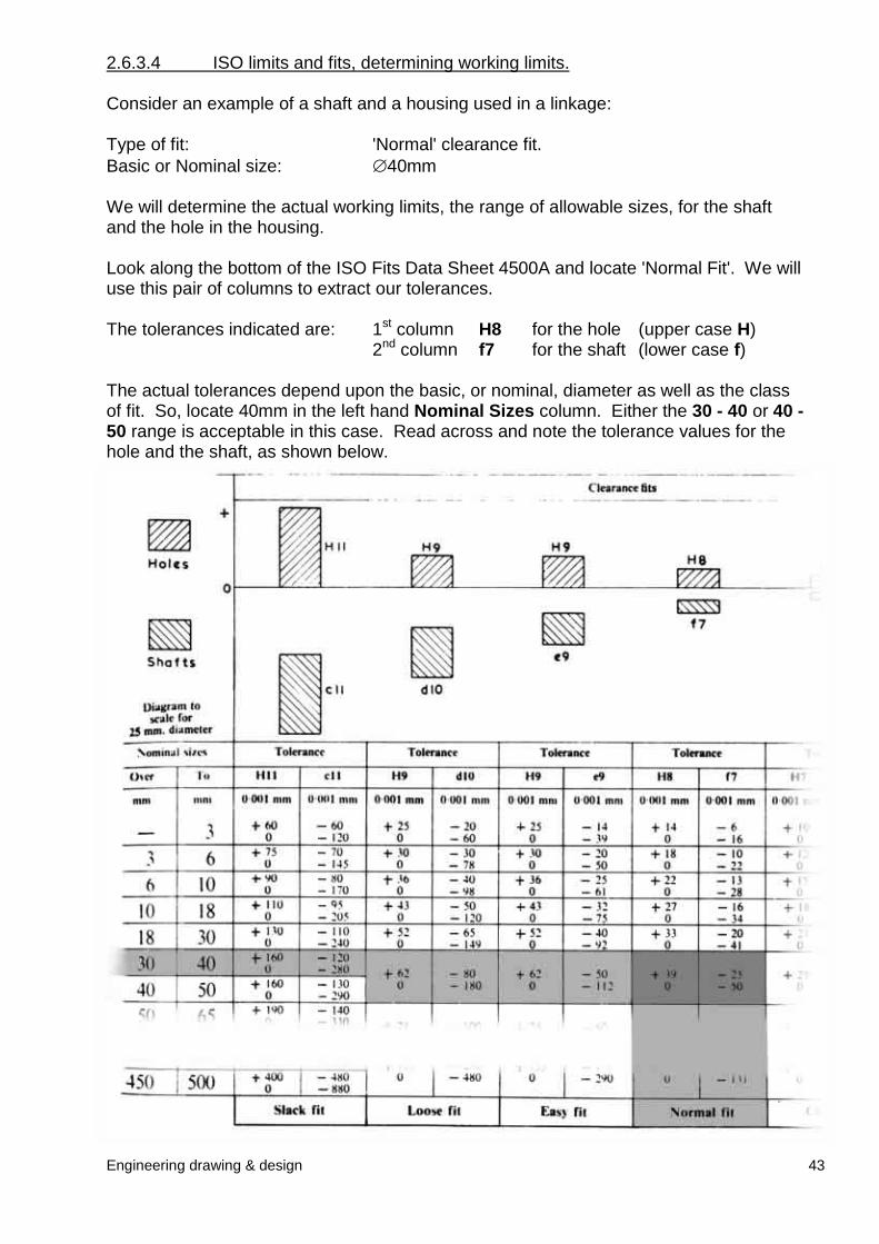
2.6.3.4 ISO limits and fits, determining working limits.
Consider an example of a shaft and a housing used in a linkage:
Type of fit: 'Normal' clearance fit. Basic or Nominal size: �40mm
We will determine the actual working limits, the range of allowable sizes, for the shaftand the hole in the housing.
Look along the bottom of the ISO Fits Data Sheet 4500A and locate 'Normal Fit'. We willuse this pair of columns to extract our tolerances.
The tolerances indicated are: 1st column H8 for the hole (upper case H)2nd column f7 for the shaft (lower case f)
The actual tolerances depend upon the basic, or nominal, diameter as well as the classof fit. So, locate 40mm in the left hand Nominal Sizes column. Either the 30 - 40 or 40 -50 range is acceptable in this case. Read across and note the tolerance values for thehole and the shaft, as shown below.
43
Engineering drawing & design 44
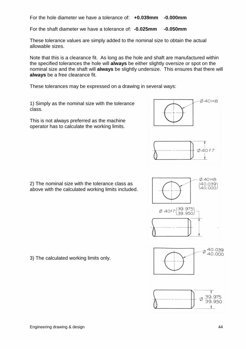
For the hole diameter we have a tolerance of: +0.039mm -0.000mm
For the shaft diameter we have a tolerance of: -0.025mm -0.050mm
These tolerance values are simply added to the nominal size to obtain the actualallowable sizes.
Note that this is a clearance fit. As long as the hole and shaft are manufactured withinthe specified tolerances the hole will always be either slightly oversize or spot on thenominal size and the shaft will always be slightly undersize. This ensures that there willalways be a free clearance fit.
These tolerances may be expressed on a drawing in several ways:
1) Simply as the nominal size with the toleranceclass.
This is not always preferred as the machineoperator has to calculate the working limits.
2) The nominal size with the tolerance class asabove with the calculated working limits included.
3) The calculated working limits only.
Engineering drawing & design 45
2.6.4 Tabulated guide to types of ISO limits and fits.
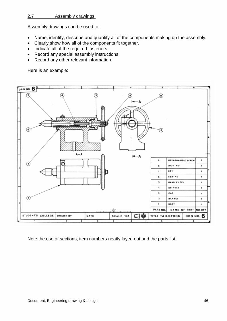
2.7 Assembly drawings.
Assembly drawings can be used to:
� Name, identify, describe and quantify all of the components making up the assembly.� Clearly show how all of the components fit together.� Indicate all of the required fasteners.� Record any special assembly instructions.� Record any other relevant information.
Here is an example:
Document: Engineering drawing & design 46
Note the use of sections, item numbers neatly layed out and the parts list.