Embed Size (px)
Citation preview

NOTESWith Assignments, Sessional Papers with Solution
and Model Question Papers
ON
ENGINEERING MECHANICS
(B.tech-1st year)
(ENGINEERING MECHANICS)
IndexUnit Topic Page No.
Unit I Two Dimensional Concurrent Force Systems 1 – 12Unit II Two Dimensional Non-Concurrent Force Systems 13–22
Unit III Centroid and Moment of Inertia 23-29Unit IV and V Kinematics and Kinetics of Rigid Body 30-35
Sessional Papers with solution 36-50Assignments 51-68
Model Question Papers 69-77
Prepared by
Mr.VIVEK KUMAR BAJPAI
Mechanical Engineering DepartmentKhwaja Moinudin chisti Urdu,Arbi-Farsi University,Lucknow
(UP)

Unit 1: Two Dimensional Concurrent Force Systems
Engineering Mechanics is that branch of science, which deals with the behavior of a rigid body, whenthe body is at rest or in motion. The Engineering Mechanics is divided into Statics (study of body at rest) and Dynamics (study of body in motion)
Definitions:
Vector Quantity: A quantity, which is completely specified by magnitude and direction, is knownas a vector quantity. Some examples: Velocity, Momentum, Force, and Acceleration.
Scalar Quantity: A quantity, which is completely specified by magnitude only, is known as ascalar quantity. Some examples: Mass, Length, Time, Temperature.
Body: A body has a definite shape and consists of number of particles.
Particle: A particle is a body of infinitely small volume, whose mass is considered to beconcentrated at a point.
Mass: Mass is an indication of the quantity of matter present within a system. (m)
Weight: Weight is a force, which the system exerts due to gravitational acceleration. Weight isactually the force with which the system is attracted towards the earth. ( W = m x g )
Force System:
Different forces acting on a body can be termed as a Force system and it can be further classified as:
1. Coplanar Forces: Forces of a force system lie 2. Non Coplanar Forces: Forces of a force system liein same plane. in different plane.
Forces are also classified as:
a. Collinear forces: Forces acting in same line of action. They may be in same direction (Like forces) or in opposite direction (Unlike forces).
Q P
1
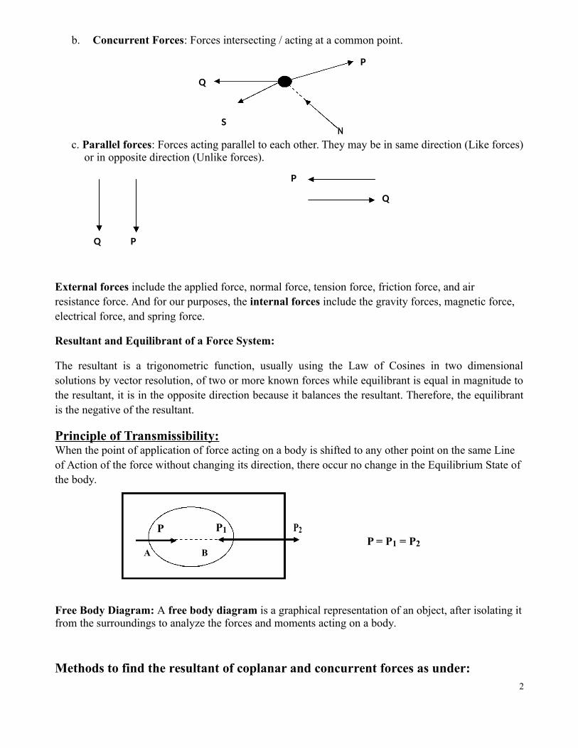
b. Concurrent Forces: Forces intersecting / acting at a common point.
P
Q
SN
c. Parallel forces: Forces acting parallel to each other. They may be in same direction (Like forces)or in opposite direction (Unlike forces).
P
Q
Q P
External forces include the applied force, normal force, tension force, friction force, and air resistance force. And for our purposes, the internal forces include the gravity forces, magnetic force, electrical force, and spring force.
Resultant and Equilibrant of a Force System:
The resultant is a trigonometric function, usually using the Law of Cosines in two dimensionalsolutions by vector resolution, of two or more known forces while equilibrant is equal in magnitude tothe resultant, it is in the opposite direction because it balances the resultant. Therefore, the equilibrantis the negative of the resultant.
Principle of Transmissibility:When the point of application of force acting on a body is shifted to any other point on the same Line of Action of the force without changing its direction, there occur no change in the Equilibrium State ofthe body.
P P1 P2
P = P1 = P2A B
Free Body Diagram: A free body diagram is a graphical representation of an object, after isolating itfrom the surroundings to analyze the forces and moments acting on a body.
Methods to find the resultant of coplanar and concurrent forces as under:2

a. Triangle Law of Forces:If two forces (P and Q) are acting simultaneously on a body are represented by the sides of a triangle takenin order, the closing side of the triangle (R) taken in the opposite order represents their resultant.
Q R Q
θ θ P P
b. Law of Parallelogram of Forces:If two coplanar forces (P and Q) are acting at a point (i.e. concurrent force) be represented in magnitude and direction by the two adjacent sides of a parallelogram, then there resultant (R) is represented in magnitude and direction by the diagonal of the parallelogram passing through that point. The position of Resultant (R) with P is α.
Q R2 = P2 + Q2 + 2PQ Cos θ;
R tan α = Q Sin θ / (P + Q Cos θ)
θα
c. Lami’s Theorem:Lami’s theorem states that if a body is in equilibrium under the action of three forces, then each force
is proportional to the Sine of angle between the other two forces. P Q
P Q S θ----- = ----- = ------ β αSin α Sin β Sin θ
S
d. Resolution of Forces: The forces are making angle θ1, θ2, θ3, and θ4, with OXP2
P3
P1
θX
P4 O
Components of Resultant Force along X axis Components of Resultant Force along Y axis
RH = P1Cos θ1 + P2Cos θ2 + P3Cos θ3 + P4Cosθ4 RV = P1Sin θ1 + P2Sin θ2 + P3Sin θ3+ P4Sinθ4
Resultant R2 = RH2 + RV
2 tan α = Rv / RH
Unit II: Two Dimensional Non-Concurrent Force Systems3

Moment of a Force:The product of a force and the perpendicular distance of the line of action of the force from a point is known as moment of the force about that point.
»M = F x d
F
d
A
Varignon’s Theorem (Law of Moments):Varignon’s theorem states that the moment of a force about any point is equal to the algebraicsum of the moments of its components about that point.
M
Moment of Force P about A =N θ
P P x AN
This can be calculated as perL Varignon’s theorem:
A
Principle of Moments:
Principle of Moments states that the moment of the resultant of a number of forces about any point is equal to the algebraic sum of the moments of all the forces of the system about the same point.
∑ Clockwise moment = ∑ Anti-clockwise moment for equilibrium condition
Couple: When two forces equal in magnitude and opposite in direction and separated by a definite distance are set to form a couple. C = P x d
P
d
P
4

Friction
Introduction:
In the previous chapters it is assumed that the contact surface between two bodies is perfectly smoothin nature, so the bodies freely slide tangentially over one another but have no movement in the normaldirection. To find an ideal condition of perfect smooth surface is not possible, even a glass surface orhighly polished metal surface has some sort of surface irregularities, which can be seen throughpowerful magnification.
With such irregularities when one body slides or tends to slide over another body, a resistance isoffered to its motion in opposite direction (tangential). This tangential resisting force is known as theforce of friction, frictional force or simply friction and generally represented by “F”.
R
P P
WPerfectly smooth surface
Figure: Tangential Force (P) applied on a body kept on a perfectly smooth surface
From above figure it is clear that if a body is kept on as perfectly smooth surface, it will not be stable /equilibrium if a force P in tangential direction is applied on the body.
R
P P
F
Rough surfaceW
Figure: Tangential Force (P) applied on a body kept on a rough surface
Friction is considered as a necessary devil. In our day to day life we experience friction everywhere.Wear and tear of all parts having relative velocity causes loss of energy and power and reducesefficiency of machine parts resulting in financial losses. But at the same time friction is very muchneeded for our day to activities such as Friction between meteorite and air helps to increase itstemperature and ignite it, protecting the living things on Earth. We can hold objects in our hand due tofriction between finger prints and object. Foot prints increase friction and helps to stand up, andengineering equipments like belt and pulley, brakes and clutch systems, lifting machines etc.
5
Friction & its features:
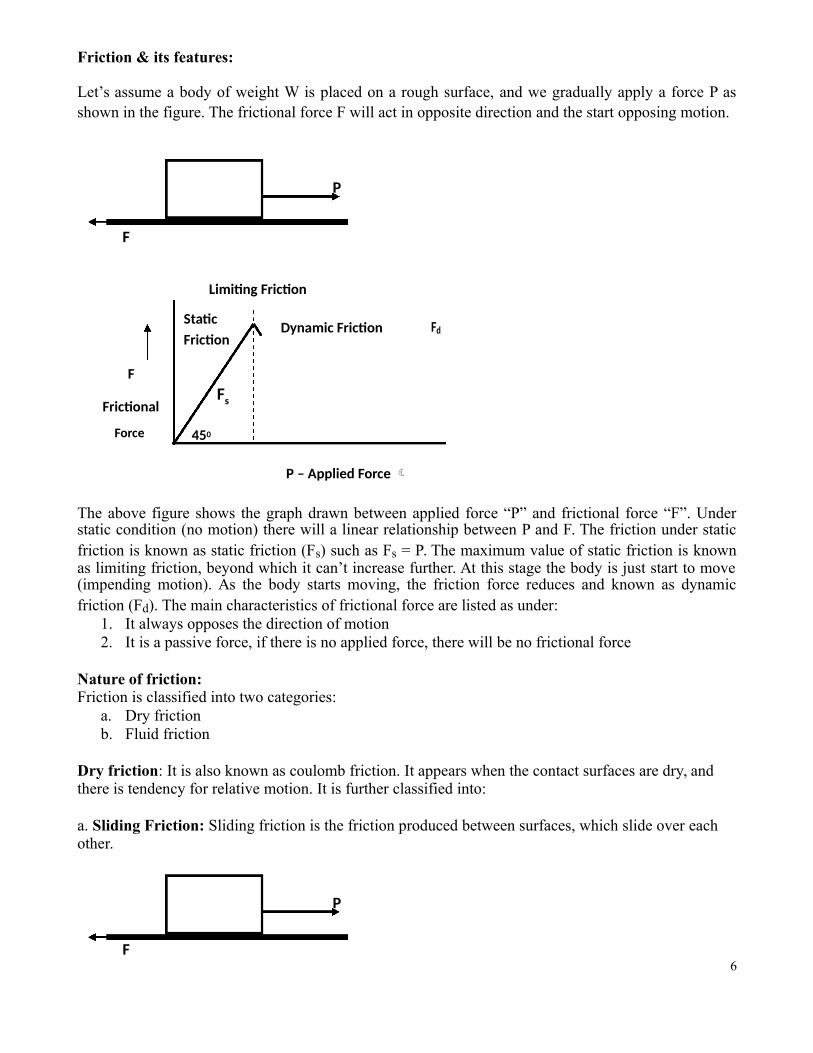
Let’s assume a body of weight W is placed on a rough surface, and we gradually apply a force P asshown in the figure. The frictional force F will act in opposite direction and the start opposing motion.
P
F
Limiting Friction
Static Dynamic Friction FdFriction
F
FrictionalFs
Force 450
P – Applied Force
The above figure shows the graph drawn between applied force “P” and frictional force “F”. Understatic condition (no motion) there will a linear relationship between P and F. The friction under staticfriction is known as static friction (Fs) such as Fs = P. The maximum value of static friction is knownas limiting friction, beyond which it can’t increase further. At this stage the body is just start to move(impending motion). As the body starts moving, the friction force reduces and known as dynamicfriction (Fd). The main characteristics of frictional force are listed as under:
1. It always opposes the direction of motion2. It is a passive force, if there is no applied force, there will be no frictional force
Nature of friction:Friction is classified into two categories:
a. Dry frictionb. Fluid friction
Dry friction: It is also known as coulomb friction. It appears when the contact surfaces are dry, and there is tendency for relative motion. It is further classified into:
a. Sliding Friction: Sliding friction is the friction produced between surfaces, which slide over each other.
P
F6
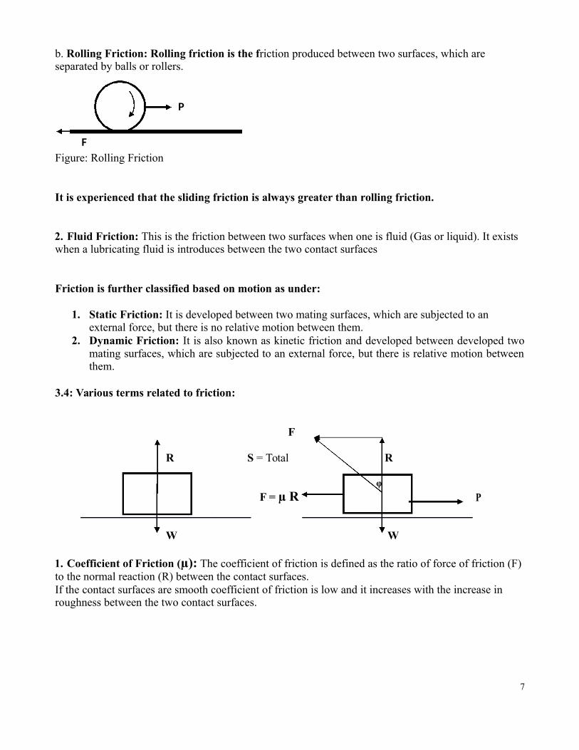
b. Rolling Friction: Rolling friction is the friction produced between two surfaces, which are separated by balls or rollers.
P
FFigure: Rolling Friction
It is experienced that the sliding friction is always greater than rolling friction.
2. Fluid Friction: This is the friction between two surfaces when one is fluid (Gas or liquid). It exists when a lubricating fluid is introduces between the two contact surfaces
Friction is further classified based on motion as under:
1. Static Friction: It is developed between two mating surfaces, which are subjected to an external force, but there is no relative motion between them.
2. Dynamic Friction: It is also known as kinetic friction and developed between developed twomating surfaces, which are subjected to an external force, but there is relative motion betweenthem.
3.4: Various terms related to friction:
F
R S = Total R
φ
F = µ R P
W W
1. Coefficient of Friction (µ): The coefficient of friction is defined as the ratio of force of friction (F) to the normal reaction (R) between the contact surfaces.If the contact surfaces are smooth coefficient of friction is low and it increases with the increase in roughness between the two contact surfaces.
7

Following Table shows the approximate coefficient of friction between various materials
Sr. Materials Static friction, µsNo.
1 Aluminium Steel 0.61
2 Copper Steel 0.53
3 Brass Steel 0.51
4 Cast iron Copper 1.05
5 Cast iron Zinc 0.85
6 Concrete (wet) Rubber 0.30
7 Concrete (dry) Rubber 1.0
8 Concrete Wood 0.62
9 Copper Glass 0.68
10 Glass Glass 0.94
11 Metal Wood 0.2 to 0.6
12 Steel Steel 0.80
13 Wood Wood 0.25–0.5
14 Rope Wood 0.5 to 0.70
15 Leather Metal 0.3 to 0.5
8
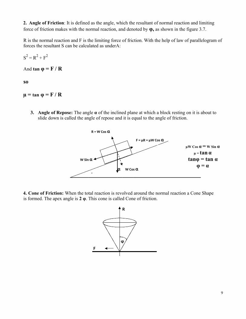
2. Angle of Friction: It is defined as the angle, which the resultant of normal reaction and limiting force of friction makes with the normal reaction, and denoted by φ, as shown in the figure 3.7.
R is the normal reaction and F is the limiting force of friction. With the help of law of parallelogram offorces the resultant S can be calculated as underA:
S2 = R2 + F2
And tan φ = F / R
so
µ = tan φ = F / R
3. Angle of Repose: The angle α of the inclined plane at which a block resting on it is about to slide down is called the angle of repose and it is equal to the angle of friction.
R = W Cos α
F = µR = µW Cos αµW Cos α = W Sin α
W Sin αµ = tan α
tanφ = tan α
αφ = α
W Cos αα
4. Cone of Friction: When the total reaction is revolved around the normal reaction a Cone Shape is formed. The apex angle is 2 φ. This cone is called Cone of friction.
R
φ
F
9

Laws of Limiting friction (Laws of Coulomb friction):
The laws of coulomb friction which are based on experimental evidences are listed as under:
1. The magnitude of the limiting (maximum) static frictional force depends upon the natureof the surfaces in contact and on their roughness (or smoothness). It does not depend uponthe size or area of the surfaces.
2. The force of friction is tangential (parallel) to the surfaces in contact and its direction is opposite to the direction in which the body would start moving.
3. For the given surfaces, the limiting frictional force fs is directly proportional to the normal reaction R:
F ∞ R
F = µ R
F / R = µ
Ladder Friction:
Ladders are commonly used to climb the walls or roofs and many a times we have experienced that theladders gets slipped causing harm to the person using it. To understand this phenomenon we mustcheck the equilibrium status of all acting forces in this non concurrent force system. Following is themathematical model for few cases of a ladder.
FB = µb RB A Ladder of Length “L” m and weight “WL” is
RBWM resting against a wall making an angle ‘θ’. The
B coefficient of friction between ladder & floor is µa
wall & between ladder and wall is µb.
A person of weight WM starts climbing on the wall
WL θ{If the wall is mentioned as SMOOTH WALL it means
O M N that there is no friction, hence Coefficient of friction (µ)FA = µa RA A between wall & Ladder is zero. But the floor will not be
smooth, in such case the ladder will slip}
GivenRA
AB = L meter; Hence OA = L Cos θ and OB = L Sin θAs the weight of ladder will act at its centre: AN = ½ OA = ½ L Cos θ
Let’s assume the person will climb up to a height of X meters from A and at that point the Ladder will start sliding / slipping. Hence OM = X Cos θ
10
Considering the whole system we apply
ΣFY = 0 => µbRB+ RA = WL + WM ------ 1
ΣFx = 0 => µaRA = RB -------------- 2
From equation 1 and 2: RA = (WL + WM) / (1 + µa x µb)
Hence RB = µa {(WL + WM) / (1 + µa x µb)}
Now let’s apply the Moment Equation ΣMA = 0,
WL x AN + WM x AM = RB x OB + µbRB x OA
By putting value we will get “X” - the distance travelled by person on the Ladder.
Case II: If the person is standing at a known distance (say X meters) from “A” the angle of inclinationis to be calculated with the help of three equations we can get the sin θ /cos θ = tan θ in momentequation.
CASE III: The person is standing at a known distance (say X meters) from “A” and a horizontal Force“P” is applied at “A” (or a rope/ string / Rod is tied with Tension “T” to prevent the ladder to slide /slip. The three equations will be
ΣFY = 0 => µbRB + RA = WL + WM ------ 1ΣFx = 0 => P + µaRA = RB -------------- 2
ΣMA = 0 => WL x AN + WM x AM = Rb x OB + µbRb x OA ------------- 3
RB will be calculated from equation 3 and by putting the value in I and II we will get the value of“P” or Tension in the String / Chain / Rod.
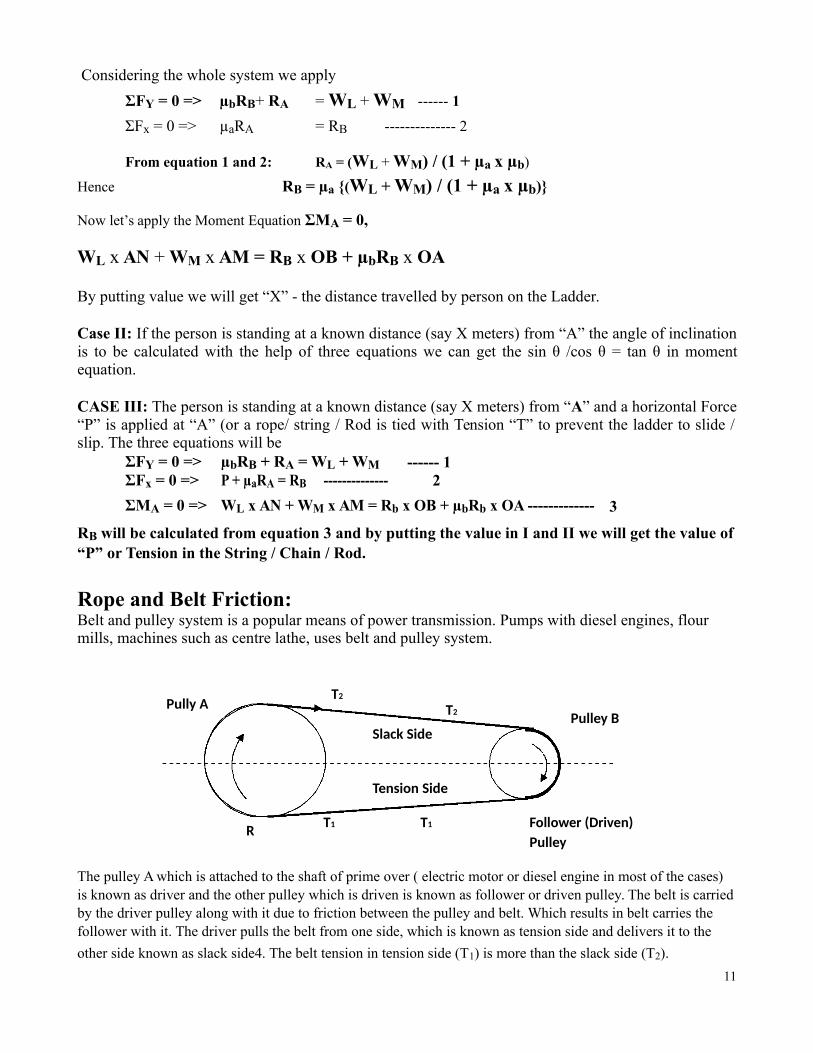
Rope and Belt Friction:Belt and pulley system is a popular means of power transmission. Pumps with diesel engines, flourmills, machines such as centre lathe, uses belt and pulley system.
Pully AT2
T2 Pulley BSlack Side
Tension Side
R T1 T1 Follower (Driven)Pulley
The pulley A which is attached to the shaft of prime over ( electric motor or diesel engine in most of the cases) is known as driver and the other pulley which is driven is known as follower or driven pulley. The belt is carriedby the driver pulley along with it due to friction between the pulley and belt. Which results in belt carries the follower with it. The driver pulls the belt from one side, which is known as tension side and delivers it to the
other side known as slack side4. The belt tension in tension side (T1) is more than the slack side (T2).
11

Belt Friction: The ratio of driving tension in Flat type Belts.R
F = μRδθ/2 δθ/2
T+ δT δθ T
T1 T2
A belt driven pulley rotating in anti clockwise direction is shown in figure.Let’s takeT1 = Tension in Tight SideT2 = Tension in Slack Sideθ = Contact angle of belt with pulleyµ = Coefficient of friction between Belt & Pulley
Let’s consider a small portion of the belt making an angle δθ with the center of pulley.Let’s T and (T + δT) are the tensions in slack and tight sides respectively.
Now it is clear from the above figure that the Belt is under equilibrium under the action of forces:
a. Tension T in slack side b. Tension T + δT in tight side
c. Normal reaction R d. Frictional Force µR
Now we will resolve the forces in horizontal direction (Tangential Direction)
µR + T cos δθ/2 = (T + δT) cos δθ/2 {Since δθ is very small cos δθ/2 = 1}
µR + T = (T + δT), hence µR = δT - --------- (1)
Now we will resolve the forces in Vertical direction (Radial Direction)
R = T sin δθ/2 + (T + δT) sin δθ/2 {Since δθ is very small sin δθ/2 = δθ/2}
R = T δθ/2 + T δθ/2 + δT δθ/2 = T δθ ----- (2) {δT δθ/2 is neglected}
Equating (1) and (2) we get,
µ (T δθ) = δT so δT/T = µ δθ on integrating we get
T2 θ
∫ δT/T = ∫ µ δθT1 0
e µθLoge (T1 / T2) = µθ; taking antilog we get T / T =1 2
12
Structural Mechanics: Trusses

Engineering Structures:Engineering Structures may be defined as systems of number of members connected to one another tosupport or transfer forces acting on them and to withstand these forces safely. When heavy loads are to be resisted or the Span is very high then a Beam cannot work. In such cases steel members such as Bars, Angles, Channels etc, are used and joined together to design Framed Structure to carry the heavy Loads.
Engineering Structures may be broadly divided into (a) Trusses (b) Frames (c) Machines
(a) Trusses: A truss may be defined as a system of uniform members joined together at their ends byriveting etc. The truss is formed from two-force members, i.e., members of truss are straight memberswith end point connections, And loads are applied only at joints. Simplest truss is triangular truss. The individual part of the structure is called Member. The members are joined either by welding or riveting/ nut & bolts. The members are Slender (cross sectional dimensions are quite small compared to thelength) and are usually of angle section, T-section, I-section etc. The roofs of sheds at Railwayplatforms, workshops and Industrial buildings, and bridges etc are some of examples of a TRUSS. Atruss is shown in below figure.
C E
F1
AB
D
F2
Figure: Truss(b) Frames: In frames, forces may act anywhere on the members. Trusses and frames are used in roofsof sheds of railway stations (platforms), workshops, buildings, bridges etc. Frames contain at least one
multi-force member, i.e., member acted upon by 3 or more forces. H
F FH
A FA B
W
BW B
T G
C
C
G
G
E D
RDX
13RDY

(c) Machines: Machines are structures designed to transmit and modify forces and they contain some moving parts. For example Centre lathe, drilling machine etc
In this chapter only analysis of plane Trusses is considered.
ClassificationTypes of Trusses: Trusses may be of following types:
a) Plane Truss or Space Truss: In plane truss all the members lie in the same plane and theforces act along the plane of the truss, e.g. Bridge Trusses and roof trusses. In Space truss allthe members do not lie in the same plane, e.g. suspension tower, Tripod etc.
b) Statically Determinate and Statically Indeterminate Truss: The force analysis can bedone by equation of static in the case of S.D.F. Only static equations are not sufficient there isneed of considering their deformation also in case of SIF.
c) Perfect or Rigid Truss: This is non-collapsible when external supports are removed. Aperfect truss is the one, which contains such number of members as are just sufficient toprevent distortion of its shape when loaded externally. A perfect truss should satisfy theequation, m = 2j – 3, where m = no. of members, j = no. of joints.
Note: Equation gives only a necessary but not a sufficient condition of a perfect truss. The onlynecessary and sufficient condition of a perfect truss is that it should retain its shape when load isapplied at any joint in any direction.
d) Imperfect Truss: Imperfect Trusses are of two types:
(i) Deficient or Collapsible Truss: A truss that contains less members than required to be justrigid and is collapsible, is known as Deficient truss. It cannot resist distortion/ retain itsshape under external load. m < 2j – 3.
C DF
A B
Figure: Deficient / Collapsible Truss
14

(ii) Redundant or Over Rigid Truss: A truss that contains more members than required to bejust rigid, is known as redundant or over rigid truss. m > 2j – 3, since number of unknowns(m+3) are more than number of equations (2j) hence such a truss is statically indeterminate.
C DF
A B
Figure: Redundant / over rigid Truss
Nature of Forces:Members can either experiences tensile force or compressive force. To phenomenon is explained through this illustration. Force P (Tensile) is applied on member AB as shown in the figure (a)
A BP P
Figure (a): A pull of P is applied at Member AB.
Now to maintain the equilibrium status an equal and opposite reaction (FAB = FBA) will bedeveloped.
A FAB FBA BP P
Now if we see only reaction in the member, it may look like that the member has acompressive force, but as reaction is always opposite in direction the member is under theinfluence of a tensile force equivalent to the reaction i.e. FAB = F BA
A FAB FBA B
And member under compressive force will look like
C FCD FDC D
P P
Members under compressive forces are called Strut, while members under tensile force areknown as Tie rod. Members with no force are known as Null members.
15

Reactions at Supports of Truss:Trusses are usually supported on hinged support at both the ends or hinged support at one end and Roller support at the other end. One support must be hinged. Otherwise the truss is of Cantilever type.
Basic Assumptions of Truss Analysis:
Following assumptions are made while making such analysis:1. All members of truss are pin joined. The forces are transmitted from one member to another through smooth pins (no friction).2. The truss is a perfect one and statically determinate.3. All the members are straight, rigid, slender, and uniform in cross section and lie in same plane.4. The external loads and reactions are acting at Joints only.5. The self-weight of members is neglected.6. Every joint is treated separately as a free body in equilibrium, i.e., the sum of all the vertical forces as well as the horizontal forces acting on the joint is equated to zero.ΣFx = 0 and ΣFY = 0
Methods of Truss Analysis:To analyze a truss means finding the forces in various members. There are two methods to find the forces in members:
a. Graphical Methodb. Analytical Method
The analytical method is further classified into two methods:1. Method of Joints2. Method of Sections
Method of joints: The following procedure is used for analysis of trussesi. Check that truss is a perfect truss (m = 2j – 3)
ii. Consider the free body diagram of entire truss and compute the support reactions using theequations of equilibrium (Rx = 0, Ry = 0, MA = 0). Determination of support reaction may notbe necessary in case of cantilever type of truss.
iii. Assume and mark directions of the axial forces in the members away from the joint on the diagram.
iv. Consider equilibrium of each joint independently and calculate magnitude of axial forces inmembers. Conditions of equilibrium are Rx = 0, Ry = 0. Hence at a time only two unknownforces can be determined. Therefore start from a joint at which not more than 2 unknown forcesappear.
v. If the magnitude of the force comes out to be negative, the nature of force in that member is compressive and if it is positive than nature of force in that member is tensile.
vi. If the force is pushing the joint, it is compressive and if it is pulling the joint, it is of tensile nature.
16
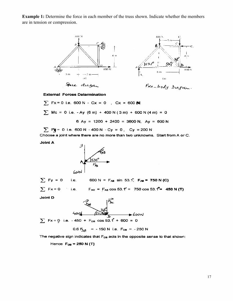
Example 1: Determine the force in each member of the truss shown. Indicate whether the members are in tension or compression.
17

Method of Sections:
In this method, the equilibrium of a portion of truss is considered which is obtained by cutting the truss by someimaginary section
Points to be considered:
The section should pass throug h the members and not through joints. A section should divide the truss into two clearly separate and unconnected portion s. A section should cut only three members since only three unknowns can be d etermined. (In special
cases, a section may cut more t han three members.) When using moment equation s, the moment can be taken about any convenient point, which may or
may not lie on the section undeer consideration.
The following steps are carried out to find forces in members through method of se ctions.
ii.Check that truss is a perfect truss (m = 2j – 3)iii.Consider the entire truss as a free body and determine reactions at the supports.
iv. Cut the truss into two separate portions by passing an imaginary section through tho se members in which forces are to be determined. (More than one such sections are possible)
v. The internal forces in these members become external forces acting on the two portio ns of the truss.vi.Assume and mark directions of t he axial forces in the cut members away from the joi nt on the diagram.
vii.Consider equilibrium of one port ion of the truss and calculate magnitude of three unknown axial forces inmembers using equations of equilibrium Rx = 0, Ry = 0, MA = 0.
Example 2: Determine the force in members GE, GC and BC of the truss shown in the Figure.Indicate whether the members are i n tension or compression.
18

4.7 Special Conditions:
Important Note:When two members meeting at a joint are not collinear and there is no externa force acting at the joint,then forces in both the me mbers are zero. (2) When there are three me mbers meeting at a joint, ofwhich two are collinear an d third be at an angle and if there is no load at the joint, the force
Example 3: For the simply supported truss shown in figure, find the force in memb ers BD, DE, EGand CE using the method of sections. (U PTU 2003, Jan’2011)
10 kNF
10 kN D
B 2.25 m
A H
C E G
1 m 1 m 1 m 1 m
Solution:
First we will calculate the reactions at support A and H. as A is a roller support it will have only one upward reaction RA, whereas at H ( Hinged support) the inclined reaction will be converted into
Horizontal and Vertical component s RHX and RHV. The free body diagram of the truss will be as under:

10 kN F
10 kN D
B
A H
C ERHX
G
RA RHY
These reactions will be calculated with the equations of equilibrium as under:
∑Fx = 0, so RHX = 0 ------ (1)
(as there was no horizontal or inclined force was acting on the truss, it was oblivious that horizontal component of reaction at hinged support is ZERO)
∑Fy = 0, so RA + RHY = 10 + 10 = 20 ------ (2)
∑MA = 0, so 4 RHY = 10 x 1 + 10 x 2 = 30
RHY = 30 / 4 = 7.5------ (3)
∑MH = 0, so 4 RA = 10 x3 + 10 x 2 = 50
RA = 50 / 4 = 12.5------ (4)
We can crosscheck our answer with the help of equation (2).
To find the force in members BD, DE, EG and CE using the method of sections, we will mark thesemembers for easy identification.
10 kN F
10 kN D
B
A H
C E G12.5 7.5
In Method of section generally we can find forces in three members at a time. We have to cut the sections twice. First sections BD, DE and EG will be cut as shown in figure to divide the truss intotwo sections.
20

10 kN F
10 kN D
B
A θ H
C E G
12.5 7.5
As we can consider LHS or RHS, LHS is selected and the forces in member BD, DE and EG are considered as Compressive.
θ = tan-1 (2.25/3) = 36.90
10 kN
B F3θ
A θF2
F1
C E
12.5 kN
We can find F1, F2 and F3 by three equations of equilibrium or by moment equation only.
∑Fx = 0
F3 cos 36.9 + F1 = 0 (1)
∑FY = 0
F3 sin 36.9 + F2 + 10 = 12.5
F3 sin 36.9 + F2 = 2.5 (2)
∑MA = 0
10 x 1 + F2 x 2 = 0
F2 x 2 = -10 / 2 = -5 kN (Tensile Force) (Member DE)
F3 sin 36.9 + (-5) = 2.5 (2)
So F3 = 7.5 / sin 36.9 = 12.5 kN (Compressive) (Member BD)
12.5 cos 36.9 + F1 = 0 (1)
F1 = - 12.5 cos 36.9 = - 10 kN (Tensile) (Member EG)
21

To find the force in the section will be cut as under:
10 kN F
10 kN Dθ
B
A F5 Hθ
CF4 E G
12.5 7.5
Let’s assume the force in cut members CE and BE are F4 and F5 respectively (both Compressive). Wehave already calculated force in member BD (12.5 kN, Comp.)
∑MB = 0
12.5 x 1 + F4 x 0.75 = 0
By similarity of triangles FG / AG = BC / AC
BC = (2.25/3) x 1= 0.75
F4 = (- 12.5 x 1) /0.75 = -16.67 kN (Tensile) in Member CE.
The final answer is tabulated as under:
Sr. No. Member Force Magnitude (kN) Nature
1 EG F1 10 Tensile
2 DE F2 5 Tensile
3 BD F3 12.5 Compressive
4 CE F4 16.67 Tensile
22

)
Unit III – Centroid and Moment of Inertia
Centre of Gravity: C.G. of a body is defined as the point through which resultant of thegravitational force (weight) acts for any orientation of the body. It depends upon the shape of thebody and may or may not necessarily be within the boundary of the body.
1. A body has only one C.G.2. Its location doesn’t change even with a change in the orientation of the solid body.3. It lies in a plane of symmetry, if any of a body.4. It is an imaginary point.
Location of C.G. / Centroid: The coordinates of C.G. (X, Y) are determined as under
A x X = a1x1 + a2x2 + a3x3 + a4x4 + ……………………………. + a4x4
X = (a1x1 + a2x2 + a3x3 + a4x4 + ……………………………. + anxn) / A
= Σ a * x / A
Similarly
Y = (a1y1 + a2y2 + a3y3 + a4y4 + ……………………………. + anyn) / A
=Σ a * y / A
X
X1
X2
X3
23
Similarly for solids (Mass)
X =Σ m * x / A
Y =Σ m * y / A
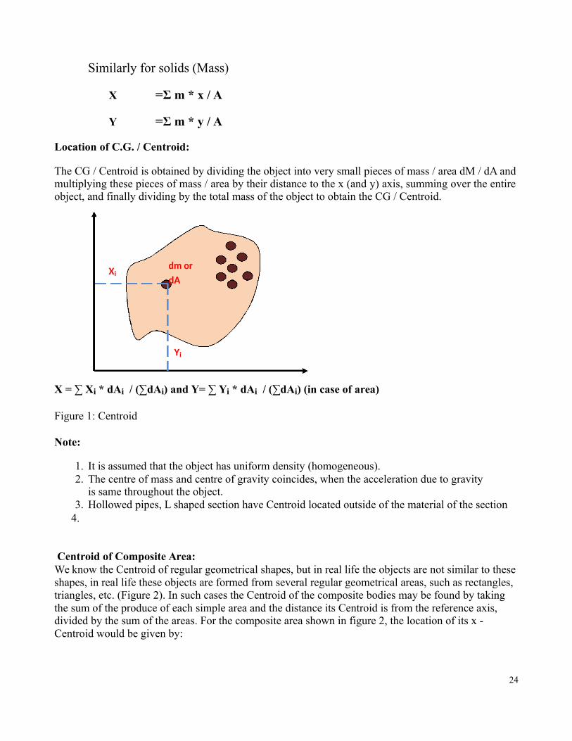
Location of C.G. / Centroid:
The CG / Centroid is obtained by dividing the object into very small pieces of mass / area dM / dA andmultiplying these pieces of mass / area by their distance to the x (and y) axis, summing over the entireobject, and finally dividing by the total mass of the object to obtain the CG / Centroid.
Xidm ordA
Yi
X = ∑ Xi * dAi / (∑dAi) and Y= ∑ Yi * dAi / (∑dAi) (in case of area)
Figure 1: Centroid
Note:
1. It is assumed that the object has uniform density (homogeneous).2. The centre of mass and centre of gravity coincides, when the acceleration due to gravity
is same throughout the object.3. Hollowed pipes, L shaped section have Centroid located outside of the material of the section
4.
Centroid of Composite Area:We know the Centroid of regular geometrical shapes, but in real life the objects are not similar to theseshapes, in real life these objects are formed from several regular geometrical areas, such as rectangles, triangles, etc. (Figure 2). In such cases the Centroid of the composite bodies may be found by taking the sum of the produce of each simple area and the distance its Centroid is from the reference axis, divided by the sum of the areas. For the composite area shown in figure 2, the location of its x - Centroid would be given by:
24

X ct = (A1 * x1 + A2 * x2 + A3 * x3 + A4 * x4 + A5 * x5) / (A1 +A2 +A3 + A4 + A5)
A1 A2
A3
A4 A5
Figure 2:
Where x1, x2, x3, and x4 are the distances from the Centroid of each simple area to the y-axis as shown in the Diagram 3. The location of the y - Centroid would be given in like manner.
Y ct = (A1 * y1 + A2 * y2 + A3 * y3 + A4 * y4 + A5 * y5) / (A1 +A2 +A3 + A4 + A5)
Important Note:1. In above example all these figures i.e. rectangle, circle, triangle and quarter circle are added to
form the composite / complex shape, so their areas are added in the above equation. In case any shape is removed from the composite shape, its area will be subtracted respectively.
2. The coordinates are in I quadrant, hence taken both (x and y) as positive. For easy calculation it is recommended that the whole body should be placed in I quadrant.
25
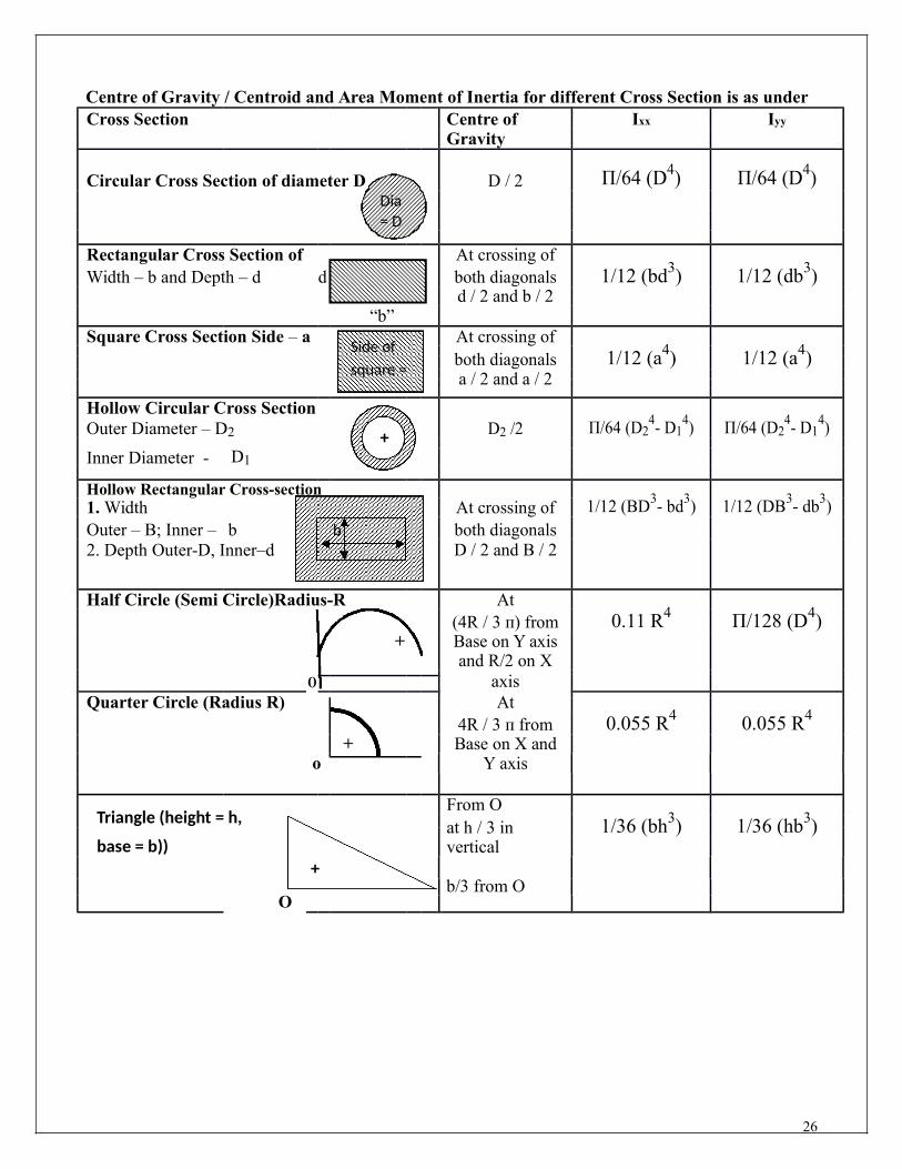
Centre of Gravity / Centroid and Area Moment of Inertia for different Cross Section is as underCross Section Centre of Ixx Iyy
Gravity
Circular Cross Section of diameter D D / 2 Π/64 (D4) Π/64 (D4)Dia= D
Rectangular Cross Section of At crossing ofWidth – b and Depth – d d both diagonals 1/12 (bd3) 1/12 (db3)
d / 2 and b / 2“b”
Square Cross Section Side – a Side of At crossing ofboth diagonals 1/12 (a4) 1/12 (a4)
square = a / 2 and a / 2
Hollow Circular Cross SectionΠ/64 (D2
4- D14) Π/64 (D2
4- D14)Outer Diameter – D2 + D2 /2
Inner Diameter - D1
Hollow Rectangular Cross-section1/12 (BD3- bd3) 1/12 (DB3- db3)1. Width At crossing of
Outer – B; Inner – b b both diagonals2. Depth Outer-D, Inner–d D / 2 and B / 2
Half Circle (Semi Circle)Radius-R At
+(4R / 3 п) from 0.11 R4 Π/128 (D4)Base on Y axis
Oand R/2 on X
axisQuarter Circle (Radius R) At
+4R / 3 п from 0.055 R4 0.055 R4
Base on X ando Y axis
Triangle (height = h,From Oat h / 3 in 1/36 (bh3) 1/36 (hb3)
base = b)) vertical+
b/3 from OO
26

Moment of Inertia (MOI ):
The Moment of Inertia (I) is a ter m used to describe the capacity of a cross-sectio n to resist bending.
Inertia refers to the property of a body by virtue of which the body resists any change in its state of restor uniform motion. Area moment of inertia is essentially a measure of resistance to bending. The massmoment of inertia gives a measure of the resistance that the body offers to change in angular velocity.
It is always considered with respect to a reference axis such as X-X or Y-Y. It is a mathematicalproperty of a section concerned with a surface area and how that area is distributed about the referenceaxis. The reference axis is usually a centroidal axis.
The moment of inertia is also k nown as the Second Moment of the Are a and is expressedmathematically as:
Ixx = Σ (A) x (y2)
In which:
Ixx = the moment of inertia around the x Axis
A = the area of the plane of the obje ct
y = the distance between the centroi d of the object and the x axis
The Moment of Inertia is an important value which is used to determine the state o f stress in a section,to calculate the resistance to buckli ng, and to determine the amount of deflection in a beam.
27

Parallel axis theorem:
The moment of inertia of any object of area “A” ( and mass – m, in case of Mass Moment of inertia) about an axis through its center of Area (mass in
case of Mass moment of inertia) is the minimum moment of inertia (Icm )for an axis in that direction in space. Th e moment of inertia about any axis parallel to that axis through the cent er of Area (mass) is given by
I = Icm + Ad2
Perpendicular axis theorem:
For a Planar object, the moment of inertia about an axis perpendicular to the plane is the sum of the moments of inertia of two perpendi cular axes through the same point in the plane of the object.
XZ
r2 = x2 + y2
x
r y MOI about ZZ = dA * r2
YC.G. Izz = ∫ dA * r2
= ∫ dA * (x2 + y2)
= ∫ dA x2 + dA y2
28

MASS MONMENT OF INERTIA OF VARIOUS VOLUMES
Mass Moment of Inertia:
Mass moment of Inertia is defined as the product of the mass and the square of the distance between the mass centre of the body and the axis.
1. Mass Moment of Inertia of a Circular Ring of uniform Cross Section:
IZZ = MR2 ; Ixx = Iyy = IZZ/2 = ½ MR2
2. Mass Moment of Inertia of a Circular Disc of radius R and thickness t about its centroidal axis:
IZZ = ½ MR2 ; Ixx = Iyy = IZZ/2 = ¼ MR2
3. Mass Moment of Inertia of a Solid Cylinder of radius “R” and height “H”:
Ixx = Iyy = M/12 (3R2 + H2)
IZZ = Ixx + Iyy = M/6 (3R2 + H2)
29
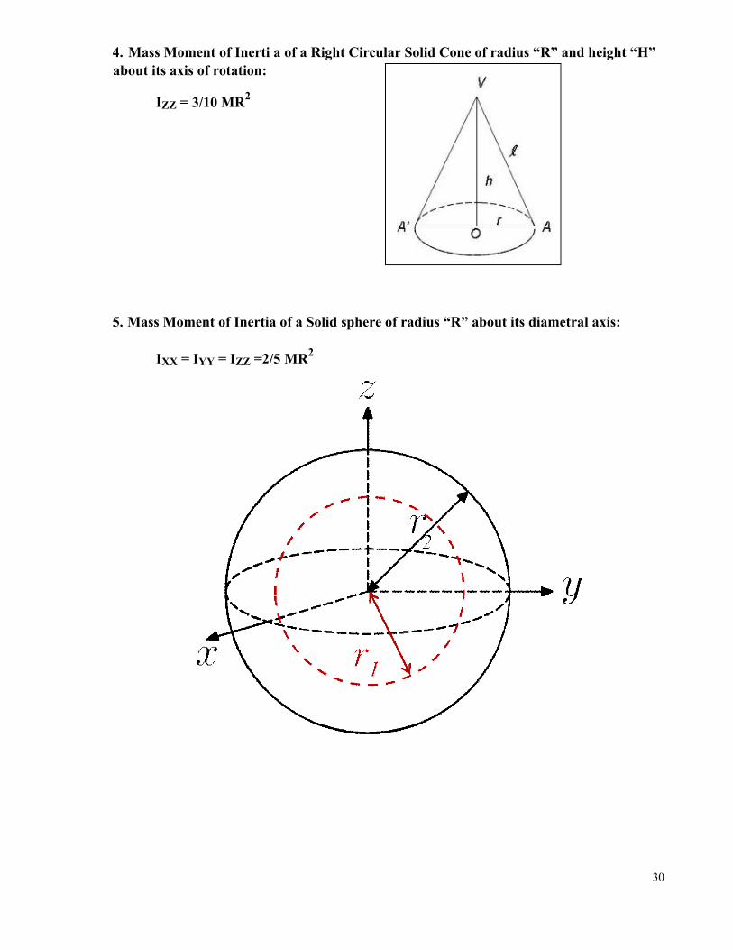
4. Mass Moment of Inerti a of a Right Circular Solid Cone of radius “R” and height “H” about its axis of rotation:
IZZ = 3/10 MR2
5. Mass Moment of Inertia of a Solid sphere of radius “R” about its diametral axis:
IXX = IYY = IZZ =2/5 MR2
30

Unit IV & V Kinematics and Kinetics of Rigid Body
Kinematics is the study of motion of a body without considering the cause of motion i.e. force.
Kinetics is the study of motion as well as the action of forces which change the motion of a body.
Distance normally refers to the total distance an object moves during a particular journey.
Displacement refers to the distance from the starting point at a particular instant in time. We normallyuse s for displacement. In other words displacement is the change in the position of a particle or abody with respect to a certain fixed reference point is referred as displacement.
Velocity: The rate of change of body with respect to time is called velocity.
Acceleration: The rate of change of velocity of a body with respect to time is called acceleration.
Motion is classified as General Plane motion, Absolute motion, relative motion, rectilinear motion,curvilinear motion, and uniform motion. The major motions are discussed below:
1. Rectilinear Motion (Linear motion) : A motion along straight line is called rectilinear motion.
Equations of rectilinear motion:
v = u + at Where u = Initial velocity in m/s
v2 = u2 + 2as v = Final velocity in m/s
s = ut + ½ at2a = Acceleration in m /s2
s = displacement in meters
t = time in sec
Relative velocity: The relative velocity of a Body “A” with respect to another body “B” will always be the algebraic difference between their velocities.
31

1. Rotation and General Plane motion: In the rotary (circular) motion, the movement of the particleis along a circular path. The particle repeats its journey along the same path about the same centre ofrotation.
a. Angular displacement (θ): The displacement of a body in rotation is called angular displacement and it is measured in radians.
b. Angular Velocity (ω): The rate of change of angular displacement of a body withrespect to time is called angular velocity. It is measured in radian per sec.
ω = dθ / dt
c. Angular acceleration (ά): The rate of change of angular displacement of a body with respect to time is called angular velocity. It is measured in radian per sec.
ά = d ω / dt = d (dθ )_/ dt x dt = d2θ / dt2
or
ά = d ω / dθ x dθ / dt = ω x d ω/dθ
Equations of Circular motion:
ω = ωo + άt Where ωo = Initial velocity in rad/s
ω2 = ωo
2 + 2 άθ ω = Final velocity in rad/s
θ =ωot + ½ άt2
Laws of Motion:
Force: The force is an external effort in the form of a push or pull, which either changes or tends to change the state of rest or of uniform motion of a body along a straight line.
Inertia: The inherent property of all the objects that they do not change their state of rest or of uniformmotion along a straight line unless acted upon by an external force, is called inertia.
a. Inertia at rest: It is inability of a body not to change by itself its position of rest.b. Inertia of Motion: It is in the inability of a body not to change by itself its state of uniform
motion along a straight line.
32

Newton’s First Law of Motion: (Law of Inertia)
If a body is at rest then it will remain at rest, or if it is moving along a straight line with a uniformspeed then it will continue to move as such, unless an external force is applied on it to change itspresent state.Linear Momentum: The product of the mass and the velocity of a body is called the linear momentum of thebody.
→ →
P = m v
Newton’s Second Law of Motion:
The rate of change of linear momentum of a body is equal to the net external force acting on the body;and the change in momentum takes place in the direction of the force. Thus a force applied to a bodyequals the mass of the body multiplied by the acceleration produced in the body in the direction of theforce.
(1 Newton force is the force, which produces an acceleration of 1 m / s2 in a body of a mass 1 kg.)
Newton’s Third Law of Motion:
Whenever a body exerts a force on another body, the second body also exerts an equal and oppositeforce on the first body
Force, Impulse and Momentum:
Force: Force is an external agent, which tends to change the state of rest or uniform motion of asystem. It is a vector quantity. It’s unit is Newton. Newton’s II law states that force is proportional tothe rate of change of momentum.
Force is specified by a) magnitude b) direction c) Point of application and line of action
Momentum: Momentum is the product of mass and velocity of a body and represents the energy ofmotion stored in a moving body.
The product of mass and velocity Force: is known as momentum of the body. Also the change in thelinear momentum per unit time is proportional to the impressed force and takes place in the directionof the force.
Momentum = m x v in kg-m / sec
Impulse: The product of force and the time during which it acts (f x t) is called impulse of force.
F x t = mVf – mVi = m(Vf – Vi)
33

The Law of Conservation of Momentum states that “Total momentum of any group of objects always remain same if no external force acts on it”
m1 – Mass
m1 – Mass
m2 – Mass
m2 – Mass
Momentum before collision = Momentum after collision
D’ALEMBERT’S PRINCIPLE:
It states that the system of forces acting on a body in motion is in dynamic equilibrium with theinertia force of the body.
Let’s consider a Body subjected to four forces as shown in the figure. It will move withacceleration “a” because of the resultant of these forces. It will remain static if a force = maacts in the reversed direction. Now for the dynamic equilibrium of the body sum of thereversed force and resultant force should be zero. As
Σ F = 0; R – ma = 0 R = ma
The force (-ma) is termed as the inertia force or reverse effective force.
R – Resultant force of all forcesF1
RF2
R
F3
a
F4 ma
34

Work done by a force on a moving body is defined as the product of the force and the distancemoved in the direction of the force.
Energy is defined as the capacity to do the work. Potential energy (mgh) is the capacity to dowork due to the position of the body and kinetic energy (½ mv2) is the capacity to do the work dueto the motion of the body.
Power is defined as the time rate of doing work. Power is F * d/t = Force * Velocity
Work Energy Principle: The work energy principle states that the work done by a system of forces (resultant force) acting on a body during a displacement is equal to the change in kinetic energy of thebody during the same displacement.
Net force (F) x d = ½ m (v2 – u2)
Virtual Work: The principle of virtual work (or principle of virtual displacements) I: if a particleis in equilibrium under the action of a number of forces (including the inertial force) the total work done by the forces for a virtual displacement is zeroThe principle of virtual work (or principle of virtual displacements) II: a particle is in equilibrium under the action of a system of forces (including the inertial force) if the total work done by the forces is zero for any virtual displacement of the particle
Radius of Gyration:
If the entire area (or mass) of the given lamina is considered to be concentrated at a point such thatthere is no change in the moment of inertia about a given axis, then distance of that point from thegiven axis is called the Radius of Gyration.
I = Ak2 (in case of Area MOI) or Mk2 (in case of mass MOI)
And radius of Gyration “Kxx” = √ (IXX / A) or √ (IXX / M)
“Kyy” = √ (Iyy / A) or √ (Iyy / M)
R2 = P2 + Q2 + 2PQ cosθ;
Important Formulae1. tan α = Q sinθ / (P + Q cosθ)
2. P / sin α = Q / sin β = R / sin γ (Lami’s theorem)
3. Σ FX = 0; Σ FY = 0; Σ M = 0 (conditions of equilibrium)
4. TT / TS = eµθ (TT = Tension in Tight Side, TS= Tension in Slack Side, θ = Angle of ontact)
5. Initial Tension = Net Driving Tension = Effective Tension in Belt = (TT - TS)
6. P (Power in kW) = {(TT - TS) * π DN} / (60 * 1000) = (TT - TS) * Velocity in m/s
(Where - D – Diameter of Pulley & N – RPM of pulley)
7. Angle of contact on case of Open Belt System: θ = 1800 - 2 α;35
Where sin α = (R2-R1) / L

SESSIONAL PAPERS withSOLUTION
36

B.TECH – FIRST SESSIONAL EXAMINATION, 2013 – 14SEMESTER – FIRST SECTION – K to SSUBJECT – ENGINEERING MECHANICS SUBJECT CODE –ME 101NAME OF STUDENT: CLASS ROLL NO.:Time: 2.00 Hours Max Marks: 60
Notes: (i) This paper is in three sections. Draw neat sketches to support your answer(ii) Marks are indicated against each section. Attempt questions from each section
as per instructions. Assume missing data suitably, if any.SECTION – A
1. Attempt ALL parts of this question: (2X6 = 12)a) Explain the various systems of forces with suitable examples.b) State the principle of transmissibility of force with its limitation.c) What do you mean by Free Body Diagram (FBD)? Illustrate with examples.d) What is equilibrium? Explain the conditions of coplanar forces.e) Classify trusses?f) State the varignon’s theorem.
SECTION – B2. Attempt ANY THREE questions. Each part has equal marks. (6X3 = 18)
a. For the given force system, find the resultant and its point of application and direction. All dimensions are in mm.
212 N88 N
45080
100280100 N
400 180 N
600
625
b. A ladder of weight 900 N and length 10 m is held in impending motion towards the right by a rope at 2.5meter along the length from bottom end and tied to the wall as shown in figure. The coefficient of frictionbetween the floor and the ladder is 0.25 and that between the wall and ladder is 0.40. Determine the tension inthe rope.
c. Find reactions at the support for the given beam as shown in figure.
10 kN 5 kN/m2 kN/m15 kN-m
3002 m 2 m 1 m 3 m 1 m
2 kN
d. Determine the forces in the members AB, BC and CD of the trussD
(each member length is 4 m) by section method. C
e. Determine an expression for the ratio of belt tensions in a flat belt drive.1 kN
A B 37

SECTION – C
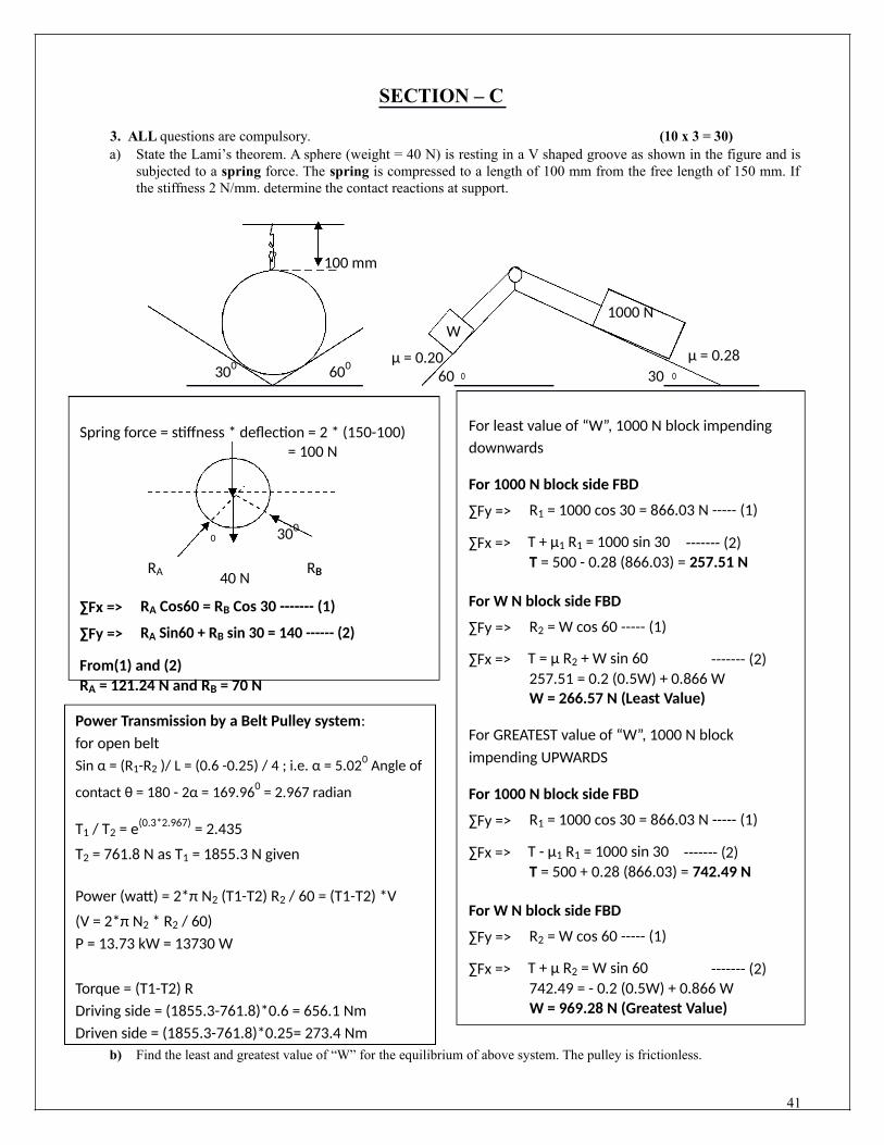
3. ALL questions are compulsory. (10 x 3 = 30)a) State the Lami’s theorem. A sphere (weight = 40 N) is resting in a V shaped groove as shown in the figure and is
subjected to a spring force. The spring is compressed to a length of 100 mm from the free length of 150 mm. Ifthe stiffness 2 N/mm. determine the contact reactions at support.
100 mm
1000 NW
300 600 µ = 0.20 µ = 0.280 060 30
b) Find the least and greatest value of “W” for the equilibrium of above system. The pulley is frictionless.
OR
State the laws of Coulombs friction? An open belt drive connects two pulleys 120 cm and 50 cmdiameter, on parallel shafts 4 meter apart. The maximum tension in the belt is 1855.3 N. The coefficient offriction is 0.3. The driver pulley of the diameter 120 cm runs at 200 rpm. Calculate (i) the power transmittedand (ii) torque on each of the two shafts.
c) Find the axial forces in all members of following truss.
10 kN
12 kN
600 600 600 300
10 m
OR
Find the axial forces in all members of the simply supported truss as shown in below fig.25 kN
A B 300
3m
E 3m D 3m C
*** All the Best ***38

Solution
SECTION – B2. Attempt ANY THREE questions. Each part has equal marks. (6X3 = 18)
a. For the given force system, find the resultant and its point of application and direction. All dimensions are in mm.
212 N 450 88 NA 80
100θ
280100 N
400 180 N
625
θ = tan (280/450) = 31.89
µBRB
T
A 600
µARA
Ladder:
RB
∑fx = -180 + 100 + 212 cos (31.89)0 = 99.825 N
∑fy = -212sin(31.89)0 – 88 = 200 N
R = √ (∑fx)2 + (∑fy)2 = √ (99.825)2 + (200)2 = 223.53 N
tan α = ∑fy / ∑fx = 200 / 99.825 i.e. α = 63.470 in 4th quadrant
This resultant will give the same moment about any point say “A”
R . x = 100*100 - 212sin 31.890 * 95 – 88*545 –
180*280 x = 99 N m / 223.53 = 0.442 m from “A”
∑fx = µaRA + T= RB -------- (1)
∑fy = RA + µbRB = 900 ------- (2)
From equations (1) and (2)
T = 1.1 RB + 225
∑MA = 0
RB *10 sin60 + µbRB * 10 cos 60 = T
(2.5 sin60) + 900*5 cos60
T = 588.76 N
b. A ladder of weight 900 N and length 10 m is held in impending motion towards the right by a rope at 2.5 meter alongthe length from bottom end and tied to the wall as shown in figure. The coefficient of friction between the floor and theladder is 0.25 and that between the wall and ladder is 0.40. Determine the tension in the rope.
c. Find reactions at the support for the given beam as shown in figure.
10 kN 5 kN/m2 kN/m15 kN-m
3002 m 2 m 1 m 3 m 1 m
FBD of Beam:
39

10 kN 7.5 kN2 kN
RAH15 kN-m RB cos 600
2 m 2 m1 m
1 m2 m 0.5 m
0.5 m RB sin 600
∑MA = 0 RAV
RB sin 600 * 9 = 10*2 -15 + 7.5*6 + 2*8.5 i.e. RB = 8.6 kN
∑fx => RAH = RB cos 60o= 4.3 kN ------- (1)
∑fy => RAV + RB sin60o = 10 + 7.5 + 2 = 19.5 ------- (2)RAV = 12.05 kN
RA = √ (4.3)2 + (12.05)2 = 12.79 kN
tan α = ∑fy / ∑fx = 12.05 / 4.3 i.e. α = 70.360 in 3rd quadrant
d. Determine the forces in the members AB, BC and CD of the truss(each member length is 4 m) by section method.
∑MB => 2*2 = 1*2 + RA*4; i.e. RA = 0.5 kN∑MA => 2*2 + 1*6 = RB*4; i.e. RB = 2.5 kN(RB not needed as taking left side)
Considering all forces in cut members as Compressive∑fx = 0
F1 + F2 cos60 + F3 = 0 ---(1)∑fy = 0RA + F2 sin60 = 2 ------ (2)
F2 = (2-0.5) / sin60; F2 = 1.732 kN (Compressive)∑MC = 0
0.5*2 + F1 * 2√3 = 0 ; F1 = - (1/3.464) = 0.289 kN (Tensile)
From equation (1) F3 = 0.577 kN (Tensile)
2 kN
F3 DC
F2
1 kNA F1
RAB
e. Determine an expression for the ratio of belt tensions in a flat belt drive. (SEE THE NOTES)
40
SECTION – C
3. ALL questions are compulsory. (10 x 3 = 30)a) State the Lami’s theorem. A sphere (weight = 40 N) is resting in a V shaped groove as shown in the figure and is
subjected to a spring force. The spring is compressed to a length of 100 mm from the free length of 150 mm. Ifthe stiffness 2 N/mm. determine the contact reactions at support.
100 mm
1000 NW
300 600 µ = 0.20 µ = 0.280 060 30
Spring force = stiffness * deflection = 2 * (150-100)= 100 N
0 300
RA 40 NRB
∑Fx => RA Cos60 = RB Cos 30 ------- (1)
∑Fy => RA Sin60 + RB sin 30 = 140 ------ (2)
From(1) and (2)RA = 121.24 N and RB = 70 N
Power Transmission by a Belt Pulley system:for open beltSin α = (R1-R2 )/ L = (0.6 -0.25) / 4 ; i.e. α = 5.020 Angle of
contact θ = 180 - 2α = 169.960 = 2.967 radian
T1 / T2 = e(0.3*2.967) = 2.435
T2 = 761.8 N as T1 = 1855.3 N given
Power (watt) = 2*π N2 (T1-T2) R2 / 60 = (T1-T2) *V
(V = 2*π N2 * R2 / 60)P = 13.73 kW = 13730 W
Torque = (T1-T2) RDriving side = (1855.3-761.8)*0.6 = 656.1 NmDriven side = (1855.3-761.8)*0.25= 273.4 Nm
For least value of “W”, 1000 N block impendingdownwards
For 1000 N block side FBD
∑Fy => R1 = 1000 cos 30 = 866.03 N ----- (1)
∑Fx => T + µ1 R1 = 1000 sin 30 ------- (2)T = 500 - 0.28 (866.03) = 257.51 N
For W N block side FBD
∑Fy => R2 = W cos 60 ----- (1)
∑Fx => T = µ R2 + W sin 60 ------- (2)257.51 = 0.2 (0.5W) + 0.866 WW = 266.57 N (Least Value)
For GREATEST value of “W”, 1000 N blockimpending UPWARDS
For 1000 N block side FBD
∑Fy => R1 = 1000 cos 30 = 866.03 N ----- (1)
∑Fx => T - µ1 R1 = 1000 sin 30 ------- (2)T = 500 + 0.28 (866.03) = 742.49 N
For W N block side FBD
∑Fy => R2 = W cos 60 ----- (1)
∑Fx => T + µ R2 = W sin 60 ------- (2)742.49 = - 0.2 (0.5W) + 0.866 WW = 969.28 N (Greatest Value)
b) Find the least and greatest value of “W” for the equilibrium of above system. The pulley is frictionless.
41

ORState the laws of Coulombs friction? An open belt drive connects two pulleys 120 cm and 50 cm
diameter, on parallel shafts 4 meter apart. The maximum tension in the belt is 1855.3 N. The coefficient offriction is 0.3. The driver pulley of the diameter 120 cm runs at 200 rpm. Calculate (i) the power transmittedand (ii) torque on each of the two shafts.
c) Find the axial forces in all members of following truss.
10 kN
D 12 kN
E
600 600 600 300
RA
CRB10 m
OR
∑MA = 0RB *10 = 10*2.5 + 12*6.25; RB = 10 kN
Hence RA = 22 - 10 = 12
kN By Joint method
FAC 6.928 kN (T)FAD 13.856 kN (C)FBC 17.32 kN (T)FBE 20 kN (C)FCE 10.392 kN (C)FCD 10.392 (T)FED 14 kN (C)
Find the axial forces in all members of the simply supported truss as shown in below fig.25 kN
A B 300
3m
E 3m D 3m C
∑ME = 0RCV *6 = 25* cos 30 *3 - 25* sin 30 *3; RCV = 4.575 kN∑Fx = 0RCH = - 25 sin 30 = -12.5 kN
∑Fy = 0RE = 25 cos 30 – RCV = 21.65- 4.575 = 17.075 kN
By Joint method
FAE 17.075 kN (C)FED 0 (Null Member)FAD 24.140 kN (T)FAB 17.070 kN (C)FBD 17.075 kN (C)FCD 17.075 kN (T)
42FBC 6.469 kN (C)

B.TECH – PRE SEMESTER EXAMINATION (I Semester), 2013 – 14 {SECTION – K to S}
SUBJECT – ENGINEERING MECHANICS SUBJECT CODE –ME 101NAME OF STUDENT: CLASS ROLL NO.:Time: 3.00 Hours Max Marks: 100
Notes: (i) This paper is in three sections. Draw neat sketches to support your answer(ii) Marks are indicated against each section. Attempt questions from each section as per
instructions. Assume missing data suitably, if any.
SECTION – A4. Attempt ALL parts of this question: (2X10 = 20)
g) Define Force. List three characteristics to describe a force.h) The resultant of two concurrent forces P = 100 N and Q = 150 N is R= 210 N. Find the angle between P and R
and Q and R.i) Write the various assumptions made in analysis of a truss.j) Define angle of repose and angle of friction.k) Define centroid and centre of gravity.l) Moment of Inertia of a semicircular lamina about its both centroidal axis is = _____ and _____m) A wheel rotating with 60 rpm accelerates with uniform angular acceleration of 1 rad / sec. Find its rpm after 2
minutes.n) State Work energy principle in brief.o) Define Work, energy, impulse and momentum.p) State and explain principle of Virtual work.
SECTION – B5. Attempt ANY THREE questions. Each part has equal marks. (10X3= 30)
a) (i) The four coplanar forces are acting at a point as shown in the figure. One force is unknown (P). The resultant is 500 N and acting along X axis. Determine the unknown force (P) and its inclination (α) with X axis.
200 NA D
ResultantP 500
B C 350
α 45⁰= 500 N
20⁰100 N W
500 N200 N
(ii) Three members AB, BC and CD are joined as shown in the above figure. A vertical weight (100 N) is hanged at B. Find the weight “W” to be attached at C to maintain the member BC in horizontal position.
b) (i) A ladder 12 m length (weight = 500 N) is resting against a smooth wall. Find the coefficient of friction between floor and ladder if ladder starts slipping when the angle between ladder and floor is ≤ 500.
(ii) Find the reactions at support for the following beam.Y
5 kN 3 m 50 mm
1 kN 100 mm
3 m 2 m 4 m X
150 mm 100 mm43
c) Determine the Centroid of the shaded area of above lamina.
(d) (i)The initial angular velocity of a rotating body is 2 rad / sec. And initial angular acceleration is zero. Therotation of the body is according to the relation α = 3t2 – 3. Find (i) angular velocity and (ii) angulardisplacement when t = 5 sec.
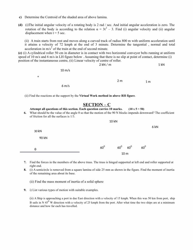
(ii) A train starts from rest and moves along a curved track of radius 800 m with uniform acceleration untilit attains a velocity of 72 kmph at the end of 3 minute. Determine the tangential , normal and totalacceleration in m/s2 of the train at the end of second minute.
(e) (i) A cylindrical roller 50 cm in diameter is in contact with two horizontal conveyor belts running at uniformspeed of 10 m/s and 6 m/s in LH figure below . Assuming that there is no slip at point of contact, determine (i)position of the instantaneous centre, (ii) Linear velocity of centre of roller.
2 kN / m 1 kN
10 m/s
+2 m 1 m
6 m/s
(ii) Find the reactions at the support by the Virtual Work method in above RH figure.
SECTION – CAttempt all questions of this section. Each question carries 10 marks. (10 x 5 = 50)
6. What should be the value of the angle θ so that the motion of the 90 N blocks impends downward? The coefficientof friction for all the surfaces is 1/3.
10 kN
6 kN30 kN
90 kN
θ 600 600 600 600
10 m
7. Find the forces in the members of the above truss. The truss is hinged supported at left end and roller supported at right end.
8. (i) A semicircle is removed from a square lamina of side 25 mm as shown in the figure. Find the moment of inertiaof the remaining area about its base.
(ii) Find the mass moment of inertia of a solid sphere
9. i) List various types of motion with suitable examples.
(ii) A Ship is approaching a port in due East direction with a velocity of 15 kmph. When this was 50 km from port, ship
B sails in N 450 W direction with a velocity of 25 kmph from the port. After what time the two ships are at a minimumdistance and how far each has travelled.

SOLUTIONSUBJECT – ENGINEERING MECHANICS SUBJECT CODE –ME 101
SECTION – ANote: For theory parts see notes / reference books.Attempt ALL parts of this question: (2X10 = 20)
b) The resultant of two concurrent forces P = 100 N and Q = 150 N is R= 210 N. Find the angle between P and R and
Q and R. (P and Q = 67.250, P & R = 41.200 hence Q & R = 26.050)
f) MOI of a semicircular lamina about its both centroidal axis is = 0.11 R4 and (π / 128) D4
A wheel rotating with 60 rpm accelerates with uniform angular acceleration of 1 rad / sec. Find its rpm after 2
minutes. ω = ω0 + αt ; ω = 2 π N / 60 hence ω0 = 2 π 60 / 60 = 2 π so ω120 = 126.28 rad / sec. So N120 = 126.28x 60 / (2 π) = 1205.9 RPM Ans.
SECTION – BAttempt ANY THREE questions. Each part has equal marks. (10X3= 30)
a) (i) The four coplanar forces are acting at a point as shown in the figure. One force is unknown (P). The resultant is 500 N and acting along X axis. Determine the unknown force (P) and its inclination (α) with X axis.
P 200 N
Resultant = 500 N α⁰
500 N20⁰
200Solution:
∑Fx => 500 = P cosα + 500 cos 20 – 200 cos 45 ------ (1)
∑Fy => P sinα + 200 sin 45 = 500 sin 20 + 200 -------- (2)From (1) and (2) P = 286.5 N and α = 53015’
(ii) Three members AB, BC and CD are joined as shown in the figure. A vertical weight (100 N) is hanged at B. Find the weight “W” to be attached at C to maintain the member BC in horizontal position.
A D500 350
B C
Solution:
100 N W
Applying Lami’s
At B TBC = (100 / sin 130) x sin 140 = 83.9 N at C At B TBC = (W / sin 145) x sin 125 = 83.9 N
So W = (83.9 x sin 125) / sin 145 = 58.74 N
45

b (i) A ladder 12 m length (weight = 500 N) is resting against a smooth wall. Find the coefficient of friction between floor and ladder if ladder starts slipping when the angle between ladder and floor is ≤ 500.
Solution: As the wall is smooth friction is zero.
RB ∑Fx => µ RA = RB --- (1) and ∑FY => RA = 500 --- (2)
500 ∑MA => 500 * 6 cos 50 = RB * 12 sin 50 so RB = 209.77500
µ RA from (1) µ = 209.77 / 500 = 0.4195 AnsRA
(ii) Find the reactions at support for the following beam.
5 kN 3 m
1 kN
3 m 2 m 4 m
RA RB
∑FY A + RB = 5 + 1 = 6 kN --- (1)
∑MA => 5 * 4 + 1 *7 - RB * 9 = 0; RB = 3 kN --- (2) and from (1) RA = 3 kN Ans.
c) Determine the Centroid of the shaded area of given lamina.
50 mm
100 mm
150 mm 100 mm
Sr. Section Area Xi YiNo.
01 Rectangle 250 x 100 125 5002 Triangle ½ x 250 x 50 250 x 2/3 100 + 50 x 2/303 Semicircle π (502) / 2 150 +50 4 (50) / (3 π)
∑A = 27325
= A1X1 + A2X2 – A3X3 / (A1 + A2 – A3) = 3381666.667 / 27325 = 123.75 mm
= A1Y1 + A2Y2 – A3Y3 / (A1 + A2 – A3) = 1895791.667 / 27325 = 69.38 mm
Ans: Centroid of the given shaded portion is (123.75 mm, 69.38 mm).
46

d) (i)The initial angular velocity of a rotating body is 2 rad / sec. And initial angular acceleration is zero.The rotation of the body is according to the relation α = 3t2 – 3. Find (i) angular velocity and (ii) angulardisplacement when t = 5 sec.
Solution:Initial angular velocity ω0 = 2 rad / sec(1) Angular Velocity (ω)We know α = dω / dt or dω = αdt ; dω = (3t2 – 3)dt
Integrating, we get ∫ dω = ∫αdt = ∫(3t2 – 3)dtω = (3t3)/3 – 3t + C
as at t = 0, ω = 2 rad / sec so 2 = 0 + 0 + C ; C =2ω = t3 – 3t + 2
when t = 5; ω5 = 53 – 3*5 + 2 = 112 rad / sec and
(2) Angular Displacement (θ)We know ω = d θ / dt or d θ = ωdtIntegrating, we get ∫ dθ = ∫ωdt = ∫(t3 – 3t + 2) dt
θ = ¼ t4 – 3/2 t2 + 2t + C1 as θ = 0 when t was 0
so C1 = 0 hence general equation θ = ¼ t4 – 3/2 t2 + 2t
so at t = 5 θ5 = ¼ 54 – 3/2 52 + 2(5) = 128.75 radians.
(ii) A train starts from rest and moves along a curved track of radius 800 m with uniform acceleration until itattains a velocity of 72 kmph at the end of 3 minute. Determine the tangential , normal and total acceleration inm/s2 of the train at the end of second minute.
Solution: As train starts from rest u = ω0 = 0 and radius = 800 mVelocity after 3 minutes v = 72 km per hour = 72 *5/18 = 20 m/s
So ω180 = V/ R = 20 / 800 = 1/40 rad / sec
As train is moving with uniform acceleration, we can use the motion equations:
ω180 = ω0 + αt ; 1/40 = 0 + α * 180 so α = 1/7200 rad / sec2
so the angular velocity after 2 minutes
ω120 = ω0 + αt = 0 + 1/7200 * 120 = 1/60 rad / sec.
Tangtential acceleration (at) = R * α = 800 * 1/7200 = 0.111 m / sec2
Normal acceleration (an) = ω2R = (1/60)2 * 800 = 0.222 m / sec2
Acceleration (a2) = at2 + an
2 so a = 0.246 m/ sec2
e) (i) A cylindrical roller 50 cm in diameter is in contact with two horizontal conveyor belts running at uniform speedof 10 m/s and 6 m/s as shown in figure. Assuming that there is no slip at point of contact, determine (i) position ofthe instantaneous centre, (ii) Linear velocity of centre of roller.
As I is the instantaneous centre so ω is uniform about I
so VA = 10 m/s = ω * IA= ω * (ID +0.5) – (1)
VD = 6 m/s = ω * ID -- (2)
A 10 m/s
C +
m/sD
47

From equations (1) and (2) ID = 0.75 m and ω = 8 rad / sec
so VC = ω * IC = 8 * 1 = 8 m/sec ---- Ans.
(ii) Find the reactions at the support by the Virtual Work method.I
2 kN / m1 kN 2 * 3 = 6
1 kN
Y2Y1 y
2 m 1 m 1.5 m
2 m 1 mSolution: RA RB
Total Virtual Work done = 0By similar triangle ratio: Y / 3 = Y1 / 2 = Y2 / 1.5
RA * 0 + (-6) *(Y2) + RB * Y1 + (-1) * Y = 0; Hence RA = 1 kN and RB = 6 kN as RA + RB = 7
SECTION – C
Attempt all questions of this section. Each question carries 10 marks. (10 x 5 = 50)3 (i) What should be the value of the angle θ so that the motion of the 90 kN blocks impends downward? The coefficient of friction for all the surfaces is 1/3.
30 kN
90 kN
θ
Solution:From FBD of upper block:∑Fy => R1 = 30 cos θ -------- (1)
∑Fx => T = 30 sin θ + 1/3 (R1) = 30 sin θ + 1/3 (30 cos θ) ------ (2)
From FBD of Lower block:
∑Fy => R2 = R1 + 90 cos θ = 30 cos θ + 90 cos θ = 120 cos θ ------ (3)
∑Fx => 90 sin θ = µ R1 + µ R2 = 1/3 [30 cos θ + 120 cos θ ] ---- (4)
90 sin θ = 50 cos θ ------ (4 )
So sin θ / cos θ = 50 / 90; hence θ = tan-1 (0.5555) = 29.050 = θ Ans
g) Find the forces in the members of the following truss. The truss is hinged supported at left end and roller supported at right end.Solution: Considering all member forces as compressive in nature.
10 kN
D F4 E 6 kN ∑Fx => RAH = 6 ------------ (1)
F3 F5∑Fy => RAV + RB = 10 ------ (2)
F2 F7 ∑MA => 10*2.5 + 6*4.33 = 10 RB ------ (3)
600 F1 600 600 F6 600 So RB = 5.10 kN and RAV = 4.10 kNA 10 m C B
RAV RB

Joint (A) Joint (B) Joint (C) Joint (D)
∑Fx => 6 + F2 + F1 = 0 - (1) ∑Fx=> F7 Cos 60 + F6 = 0 (1) ∑Fx => F3Cos60 – 8.829 = F5 ∑Fx=> 5.658 Cos∑Fy => F2 sin 60 = 4.9 --- (2) ∑Fy => F7 sin 60 = 5.1 --- (2) Cos 60 – 2.945 (1) 60 – 5.884 cos 60
So F1 = -8.829 kN (T) and So F6 = - 2.945 kN (T) and∑Fy => F3sin 60 + F5sin 60=0 = F4
So F3 = 5.884 kN (C) andF2 = 5.658 kN (C) F7 = 5.89 kN (C)
So F4 = -0.113 kN(T)
F5 = - 5.884 kN (T)
5 ((ii) A semicircle is removed from a square lamina of side 25 mm as shown in the figure. Find the moment of inertia of the remaining area about its base.
MOI of square about base = 1/12 (254) + 252 * 12.52 ---(1)
MOI of semicircle about its base = 0.11 (12.5)4 + π (12.5)2/2 * (4*12.5/3 π)2 – (2)
MOI of shaded portion = MOI of square – MOI of Semicircle = 120,620.95 mm4
II Method:
MOI of shaded portion about base = 1/3 (254) – π / 128 (254 ) = 120,620.95 mm4
6) (i) A Ship is approaching a port in due East direction with a velocity of 15 kmph. When this was 50 kmfrom port, ship B sails in N 450 W direction with a velocity of 25 kmph from the port. After what timethe two ships are at a minimum distance and how far each has travelled.
Solution:
VBX = 25 sin 45 = 17.678 kmph and VBY = 25 sin 45 = 17.678 kmph
VAX = - 15 kmph and VAY = 0
VRX = 17.678 - (-15) kmph = 32.678 kmph and VRY = 17.678 - 0 = 17.678 kmph
VR2 = 32.678 2 + 17.678 2 = 37.153 kmph
α = tan-1 (17.678 / 32.678) = 28.410
VR* t = 50 cos α ; 37.153 * t = 50 cos 28.41
So t = 1.1837 hours ---- Ans.
49

7. Explain .D’Alembert’s principle. In what distance will body of 300 N attains a velocity of 3 m/s staring from rest. What is the tension in the chord? Consider frictionless pulley.
From Free Body Diagram of 200 N Block(Considering block going upward):
Sin θ = 4/5 and cos θ = 3/5
∑Fy => R1 = 200 cos θ --- (1)
300 N
200 N4
3 µ = 0.20
µ = 0.20 θ 450
From Free Body Diagram of 300 N Block (Consideringblock going downward):
∑Fy => R2 = 300 cos θ --- (3)
∑Fx => 300*sinθ = T + µ R2 + 300/9.8* a -- (4)212.13 = T + 42.43 + 30.61 a
∑Fx => T = 200*sinθ + µ R1 + 200/9.8* a --(2) T = 200*4/5 + 0.2(200 cos θ) + 20.41a
So T = 160 + 24 + 20.41 a
So T = 169.7 – 30.61 a --- (4)From (2) and (4)
a = -0.2799 m / sec2 and T = 178.26 N
Negative acceleration shows that the direction of motion is just opposite to what we have considered.
Now as u = 0; V2 – u2 = (2 a * S) => V2 = (2 a * S)so to attain the velocity of 3 m/s the blocks will move
S = V2 / 2 a = 32 / 2*0.2799S = 16.07 m ----- Answer
50

A S S I G N M E N T S
51

ASSIGNMENT-TWO DIMENSIONAL FORCE ANALYSIS
1. Explain various force systems giving examples.2. State and explain Principle of transmissibility of a force.3. State and prove Lami’s theorem.4. The forces 20N, 30N, 40N, 50N are acting at one of the angular points of a regular hexagon, towards the other
five angular points, taken in order. Find the magnitude and direction of the resultant force.5. Determine the resultant of following force system as shown in fig.
12N 10 N
30⁰ 5 N
40⁰ 30⁰
4 N 60⁰40⁰
12 N
15 N 8 N
6. Determine the shortest length of cable which can be used to support a load of 1000 N if tension in the cable is not to exceed 720 N. Take Length of AC equal to BC
1.8 m 1.8 m
A M B
C
1000 N
7. A uniform wheel of 0.4 m diameter, weighing 8 kN, rests against a rigid rectangular block 0.1 m thick as shown in fig.. Find the least pull through the centre of the wheel to just turn it over the corner of the block. All surfaces are smooth. Find the reaction of the block as well.
PRA
O
0.1 m W52

8. Three cylinders are piled in a rectangular ditch as shown in fig. Neglecting friction, determine the reaction between cylinder C and the vertical wall. The radius of cylinders A= 5cm, B=6 cm, C=4 cm.
A
20 N
CB
40 N15 N
18 cm
9. In fig., two cylinders A of weight 400 N and B of weight 200 N, rest on smooth inclines. They are connected by abar of negligible weight hinged to each cylinder at its geometric center by smooth pins. Find the force P acting asshown that will hold the system in the given position.
A60⁰
15⁰ B
60⁰ 45⁰
53

ASSIGNMENT-TWO DIMENSIONAL FORCE ANALYSIS (II)
1. State and explain the Principle of moments.2. State and prove Varignon’s theorem.3. Define the terms: a) Moment b) moment of a force c) Couple4. A system of parallel forces acting on a lever is as shown. Determine the magnitude, direction and position of
the resultant.
200 N 125 N50 N
1.5 m 1.5 m 1 m
5. Four forces equal to 10 N, 20 N, 30 N and 40 N are respectively acting along four sides ( 1 m each) of a square ABCD, taken in order. Determine the magnitude, direction and position of the resultant.
30 N20 N
10 N
40 N6. A cylinder of weight W and radius r is supported in horizontal position against a vertical wall by a bar LM of
negligible weight. The bar is hinged to the wall at L and supported at M by a horizontal rope MN. Find the value of the angle Ө that the bar should make with the wall so that the tension in the rope is minimum. Assume frictionless conditions.
NM
S
U l
L
7. Three cables attached to a disk exert on it the forces as shown in fig. Determine resultant and specify its point of application on line AD.
110 N140 N C 20⁰
45⁰ B
A
D 45⁰
140 N 54
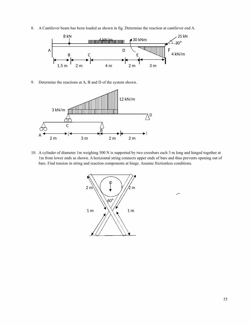
8. A Cantilever beam has been loaded as shown in fig. Determine the reaction at cantilever end A.
8 kN4 kN/m 30 kNm
25 kN
A
30⁰
B CD
EF
4 kN/m
1.5 m 2 m 4 m 2 m 3 m
9. Determine the reactions at A, B and D of the system shown.
12 kN/m
3 kN/mD
CB
A2 m 3 m 2 m2 m
10. A cylinder of diameter 1m weighing 500 N is supported by two crossbars each 3 m long and hinged together at 1m from lower ends as shown. A horizontal string connects upper ends of bars and thus prevents opening out of bars. Find tension in string and reaction components at hinge. Assume frictionless conditions.
2 m 2 m
60⁰
1 m 1 m
55

Assignment on Beam and TrussTheoretical questions:2. Define Beam. List various types of beams and loads with neat sketches.3. Write any four assumptions considered while analyzing a truss.4. Define perfect, imperfect (deficient and redundant) Frames.
Numerical Questions:
1. A simply supported beam of span 12 m is loaded with a uniformly varying load of 50 kN /m at left end and 110 kN / m at right end. Find reactions at support.
2. Find reactions at support for the following beam .
50 kN / m
3 m 6 m
3. Find reactions at support for the following beam.
40 k N / m30 k N
50 k N / m 20 k N / m
5 m 2 m 1 m 3 m
4. Find reactions at the fixed support for the following beam.
80 k N100 k N
40 k N / m
4 m 4 m
56
5. Determine the forces in all the members of the Truss by Joint Method as shown in figure.
100 kN
D90
60o 60o 30o
B
A C
8 m
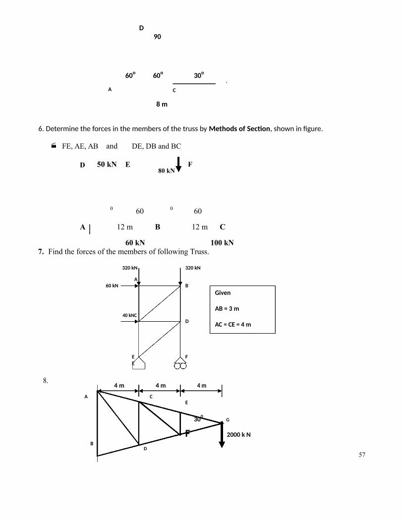
6. Determine the forces in the members of the truss by Methods of Section, shown in figure.
FE, AE, AB and DE, DB and BC
D 50 kN E80 kN
F
0 60 0 60
A 12 m B 12 m C
60 kN 100 kN7. Find the forces of the members of following Truss.
320 kN 320 kN
A60 kN B
Given
40 kNCAB = 3 m
D AC = CE = 4 m
E FE
8.4 m 4 m 4 m
A CE
300G
F 2000 k NB
D57

9) For the truss shown in the figure find the forces in GF, CD & CF members by section method.
120 kNFA G
60 kN450
AG = GF = DE = 8 m
900
BC D50 kN
10) Analyse the following truss by Joint method.
B D600
600
AC 1000 kN
11. For the truss shown in the figure find the forces in AC, AG & BC and GF, CD & CF.F
GA AG = GF = DE = 10 m
600
900 E
C D
50 kN 50 kN 50 kN
B
58
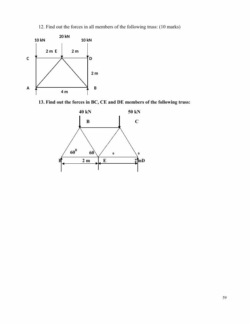
12. Find out the forces in all members of the following truss: (10 marks)
10 kN20 kN
10 kN
2 m E 2 m
C D
2 m
A4 m
B
13. Find out the forces in BC, CE and DE members of the following truss:
40 kN 50 kN
B C
60060 0 0
B 2 m E 2 mD
59

Assignment: Friction
1. A uniform ladder of length 10 m and weighing 20 N is placed against a smooth vertical with its lower end 8m from the wall. In this position the ladder is just to slip. Determine the coefficient of friction between theladder and the floor.
2. A uniform ladder 20 m long weighs 1800 N. It is placed against a wall making an angle of 60 0 with floor. Thecoefficient of friction between the wall and the ladder is 0.38 and that between the floor and the ladder is 0.33.The ladder in addition to its own weight has to support a man weighing 900 N at the top of the ladder. Calculatethe horizontal force F to be applied to the ladder at the floor level to prevent slipping.
3. A uniform ladder 5 m long weighs 300 N. It is placed against a wall making an angle 60 0 with floor. Thecoefficient of friction between the wall and the ladder is 0.25 and that between the floor and the ladder is 0.35.The ladder in addition to its own weight has to support a man weighing 900 N at the top of the ladder. Calculatethe horizontal force F to be applied to the ladder at the floor level to prevent slipping.
4. A uniform ladder 3 m long weighs 18 N. It is placed against a wall making 600 with floor. The coefficient offriction between the wall and the ladder is 0.25 and that between the floor and the ladder is 0.35. The ladder inaddition to its own weight has to support a man weighing 90 N at the top of the ladder. Calculate the horizontalforce F to be applied to the ladder at the floor level to prevent slipping.
5. Calculate the push required to keep a ladder (length 8 m, weight = 750 N) in equilibrium, while a person(weight 1000 N) standing at the top. The ladder makes an angle of 200 with wall and take coefficient offriction for wall and surface = 0.3.
6. Determine the minimum angle which can be made by a ladder with the floor and leaning against a smoothwall without slipping under its own weight while supporting a person at top, whose weight is double theweight of the ladder. Take µ = 0.35 wherever applicable.
7. The weight of a 12 m long ladder is 2000 N and it is placed against a wall making an angle of 580 with floor.The coefficient of friction between wall and ladder is 0.30 and floor and ladder is 0.32. Calculate up to whatlength a person of weight 800 N can climb the ladder.
8. Derive T1 / T2 = e µθ for an open belt drive system.
9. A belt is running over a pulley of diameter 120 cm at 200 rpm. The angle of contact is 1650 & coefficient offriction between the belt & pulley is 0.3. If the maximum tension in the belt is 3000 N. Find the powertransmitted by the belt.
60

Assignment Unit III (CG, Centroid & Moment of Inertia)
1. Define Centriod, Centre of gravity, and moment of inertia.2. Derive the equtaion of mass moment of inertia for a circular Ring.3. Derive the equation for the Mass MOI for a uniform Circular plate.4. Derive an expression for the mass moment of inertia of a solid uniform circular cone.5. Derive an expression for the mass moment of inertia of a Sphere.6. Derive an expression of the moment of inertia of a rectangular section about an axis passing
through its centroid.7. Two equal circular plates of maximum possible diameters are being cut from a square
metalic sheet (size 800 x 800 mm). Calculate the moment of inertia of the reamining shape.8. Calculate the Polar MOI of an equilateral triangle (side = 20 cm) about its vertex.9. Locate the centroidal of a “Z” section as shown in the figure. All dimensions are in cm.10. Calculate the Polar MOI of an equilateral triangle (side = 20 cm) about its vertex.11. Show that the product of inertia of an area about two mutually perpendicular axes is zero, if
the area is symmetrical about one of these axes.12. A uniform lamina as shown in fig. on page no.5 consists of a rectangle, a semicircle & a
triangle. Determine the CG of the lamina. All dimensions are in mm.
13. Locate the centroidal of a “Z” section as shown in the figure. All dimensions are in cm.
10
Web and Flangethickness = 5 cm
25
35
14. A circle is cut from a circle of diameter 450 mm as shown in the above figure. Calculate the polar
moment of Inertia of the remaining shape.
15. Find the moment of inertia of an “L” shaped body of height and base as 200 mm each and web and flange thickness 20 mm about X axis.
16. From a circular plate of diameter 100 mm a circular part is cut out whose diameter is 50 mm. Find the centroid of the remainder.
61

17. Determine the moment of inertia of the section about an axis passing through the base of a equilateral triangle (side 150 mm).
18. Find the centroid of the given figure:
200 mm400mm
0 600
60 600 mm
62

ASSIGNMENTS
ASSIGNMENT-KINEMATICS (RECTILINEAR, CURVILINEAR AND ROTARY MOTION)
1. Distinguish between :a) Statics and dynamicsb) Kinematics and kineticsc) Rectilinear motion and curvilinear motion.
2. Express the acceleration of a particle in tangential and normal components.
3. The position of a particle in rectilinear motion is defined by the relation x=t3+t2+t+1, where x is in metres and t is in seconds. Determine its position, velocity and acceleration at time t=2 s.
4. The acceleration of a particle in rectilinear motion is defined by the relation a=kt2 -3. Given that at t=0 s, v=0 m/s and x=0 and at t=3 s, v=9 m/s, determine its position, velocity and acceleration at t=2s.
5. Two trains start at same time from stations A and B (6 km apart) respectively in opposite tracks. Train A accelerates uniformly at the rate of 0.5m/s2 until it reaches a speed of 54 kmph. While train B accelerates uniformly at the rate of 0.6 m/s2 until it reaches a speed of 72 kmph and then travels at this speed. Determine when and where both will cross each other.
6. A balloon is ascending from the ground at a constant acceleration of 0.5 m/s2. After 30 seconds from thestart, a ball is released from the balloon. Determine the velocity with which it will strike the ground andthe time taken to reach the ground.
7. Track repairs are going on a 2 km length of a railway track. The maximum speed of the train is 90 km/h. The speed over the repair track is 36 km/h. If the train on approaching the repair track deceleratesuniformly from the full speed of 90 km/h to 36 km/h in a distance of 200 m and after covering the repair track accelerates uniformly to full speed from 36 km/h in a distance of 1600 m, find the time lost due to reduction of the speed in the repair track.
8. A wheel starting from rest is accelerated at the rate of 5 rad/s2 for an interval of 10 sec. If it is then made to stop in the next 5 sec by applying brakes, determine
(i) The maximum velocity attained(ii) Total angle turned.9. A wheel rotates with uniform angular acceleration. If the angles turned during the third and the sixth
second be 8 radians and 11 radians respectively, determine the initial angular velocity of the wheel andthe angular acceleration.
10. The angular rotation in radians of an accelerated flywheel is given by Ө= 329t2. Find the linear velocity and acceleration of a point at a distance of 0.75m from
the axis of rotation at the instant when its tangential and normal accelerations are equal.
11. The angular acceleration of the disc is defined by the relation α= 3t2-2t. Determine the expressions for angular velocity and displacement given that the disc is initially at rest at Ө=0.
12. A motorist is driving at 80 km/hr on a curved position of a highway of 400 m radius. He suddenly applies brakes and that causes the speed to decrease to 45 km/hr at a constant rate in 8 sec. Determine the tangential and normal components of acceleration immediately after the application of brakes and 4 seconds later.
63

ASSIGNMENT-KINEMATICS (RELATIVE VELOCITY AND GENERAL PLANE MOTION)
1. Define General plane motion and give examples.2. What are the various methods used to analyze the general plane motion. Discuss them.3. Define instantaneous center of rotation.4. Hailstones fall vertically at a velocity of 5 m/s on to the deck of a ship steaming at 8 m/s. Find
the direction of motion of hailstone as felt by an observer on the deck and its apparent velocity.5. When a cyclist is riding west at 24 km/h he finds the rain meeting him at an angle of 45⁰ with the vertical. When he rides at 16 km/h he meets the rain at an angle of 30⁰
with the vertical. What is the actual velocity in magnitude and direction of the rain.
6. A cylinder of radius 20 cm rolls without slipping along a horizontal plane PQ. Its center has a uniform velocity of 25 m/s. Find the velocity of the points A and B on the circumference of the cylinder.
B
AC
0.20 m
D
7. A string is wound round at a pulley 250 mm in diameter. One of its end is fixed to the pulley while theother is fixed to the weight hanging freely. This weight describes a distance of 10 m after starting fromrest, in five seconds. Find the angular velocity reached at the end of the above displacement. Also findthe distance moved by the weight to make the pulley rotate at 300 rpm.
8. A long rod AB is supported at the upper edge of a wall of height h= 2m, and on a horizontal floor as shown
in the figure. If the lower end of the rod moves with a velocity of va= 1 m/s, find the velocity of the contactpoint C of the rod and the angular velocity of the contact point C of the rod and the angularvelocity of the rod, when the rod is at 60⁰ to the horizontal.
BC
v
h= 2m
va A60⁰
9. A pulley and two loads are connected by inextensible strings as shown in fig. The load A has uniform
acceleration of 3 m/s2 and an initial velocity of 4.5 m/s both directed downwards. Find(a) The number of revolutions executed by pulley in 4 sec.(b) The velocity and position of load B after 4 sec.(c) The acceleration of point C at t=0.
C1m
B
A 64
1.5m

ASSIGNMENT-KINETICS OF RIGID BODIES
a. Write brief note ona) D’Alembert’s Principle and its applications.b) Principle of conservation of Energy and its application.c) Principle of conservation of momentum and its applications.
b. Define the terms:a) Work-energy principleb) Impulsec) Momentum
3. Two bodies directly in line and 10m apart are held stationery on an inclined plane having inclination of 20⁰. The coefficient offriction between plane and lower body is 0.08 and that between the plane and upper body is 0.05. If both the bodies are set inmotion at the same instant, calculate the distance through which each body travels before they meet together.
10. An elevator together with the passengers weighing 2 tons is supported by a cable. Determine the acceleration of the lift when the tension in the cable is
a) 23 kN when the lift is moving upwardsb) 18 kN when it is moving upwardsc) 16kN when the lift is moving downwardsd) 21 kN when it is moving downwards
11. Determine the acceleration of the system of blocks shown in fig. Assume the pulleys to be
massless and frictionless. Take m1 = 8kg, m2= 2 kg and m3= 3 kg. Also, determine the tension in the strings connecting the blocks.
1
23
12. Two bodies of weights 40 N and 25 N are connected to the two ends of a light inextensible string, which passes over a smooth pulley. The weight 40 N is placed on a rough inclined plane, while the weight 25 N is hanging free in the air. If the angle of the plane is 15⁰, and
coefficient of friction between the weight 40 N and the inclined surface is 0.2, determine :a) Acceleration of the system Tension in the string c) Distance
moved by the weight 25 N in 3 sec starting from rest
65

.13. A constant force of 100 N is applied as shown tangentially on a cylinder at rest, whose mass
is 50 kg and radius is 10 cm, for a distance of 5 m. Determine the angular velocity of the cylinder and the velocity of its center of mass. Assume that there is no slip.
100 N
cm
14. A 10 gm bullet is shot horizontally in a wood block of mass 1 kg. The bullet gets embeddedin the block and the block is displaced on a rough horizontal table (µ = 0.2) through 1 m. What was the velocity of the bullet?
15. Two weights 800 N and 200 N are connected by a thread and move along a rough horizontal plane under the action of a force 400 N applied to the first weight of 800 N as shown in fig. The coefficient of friction between the sliding surfaces of the weights and theplane is 0.3. Determine the acceleration of weights and the tension in the thread using D’Alembert’s principle.
200 N 800 N 400 N
16. A block of 10 kg mass slides down an inclined plane with a slope angle of 35⁰. It is stopped by a spring of stiffness 1 kN/m. If the block slides down 5 m before hitting the spring then determine the maximum compression of the spring. The coefficient of friction between the block and the inclined plane is 0.15.
17. Two blocks are connected by inextensible wires as shown in fig. Find by how much distance block 400 N will move in increasing its velocity to 5m/s from 2 m/s. Assumepulleys are frictionless and weightless.
600 N400 N
66

ASSIGNMENT-VIRTUAL WORK
1. Define virtual displacement and virtual work.2. State the principle of virtual work.3. Discuss the advantages of the method of virtual work over the method of equilibrium equations
to determine the unknown forces in a system of forces acting on the body.4. Five rods AB, BC, CD, DA and BD each of equal length and equal cross-section are pin-jointed together so
as to form a plane frame ABCD. The frame ABCD has a rhombus shape with one horizontal diagonal BD. The frame is suspended from topmost joint A. A weight W is attached at the lowermost joint C. Neglecting the self-weight of the frame and using the method of virtual work, find themagnitude of thrust in member BD.
A
a a
B D
a a
C
W
5. A weightless ladder AB is supported as shown in fig. carries a vertical load of 6000N. Find the force P required horizontally at B to keep the ladder in equilibrium, by the principle of virtual work. Assume allcontact surfaces as smooth.
Rw W=6000 N
9 m
60 P
6. A beam AB of span 5 m is carrying a point load of 2 kN at a distance of 2m from A. Determine thebeam reactions, by using the principle of virtual work.
7. Using the method of virtual work, find the support reactions for the simply supported beam AB loadedas shown in fig.
30kN/m 100N 3 m
6 m 10m
67

8. A uniform ladder of weight 250 N rests with its upper end against a smooth vertical wall andits foot on a rough horizontal ground making an angle of 45⁰ with the ground. Find the forceof friction of ground using the method of virtual work.
Rw
W
F
R
9. A weight of 1000 N resting over a smooth surface inclined at 30⁰ with the horizontal is supported by an effort P resting on a smooth surface inclined at 45⁰ with the horizontal as shown in fig.
1000N CP
A B30⁰ 45⁰
68

MODELQUESTION
PAPERS

ENGINEERING MECHANICS ME 101 (MODEL PAPER (1))
B.Tech. I Year (SEM. I) EXAMINATION, 2013-14Time: 3 Hours Total Marks: 100Note: (1) This paper is in three sections. Section A carries 20 marks. Section B carries 30 marks and
Section C carries 50 marks.(2) Attempt all questions. Marks are indicated against each question / part.(3) Assume missing data suitable if any.
SECTION – A1. Attempt all parts of this question [2x10=20]
a) Discuss the equilibrium condition for coplanar force system.b) Find the weight of the block placed on a inclined plane making an angle of 300 with horizontal. Thecomponent of this block parallel to the inclined plane is 100 N.c) Explain the laws of static frictiond) What is a zero force member (Null Member) in a truss. How you will identify it.e) State parallel axis theoremf) State perpendicular axis theoremg) A car starts from rest with uniform acceleration of 1.2 m/sec2. After achieving 100 kmph a sudden brake isapplied to stop the car with retardation of 1.4 m/sec2. Find the distance travelled during this period.h) What is the relationship between angular velocity and revolutions per minute (r.p.m.) of a body?i) Explain principle of conservation of momentum with neat sketchesj) Find the force required to pull a block of 1 kN on a rough horizontal plane (µ = 2/5) with an acceleration of2 m/sec2.
SECTION – B2 Answer any three parts of the following: [10x3=30]a) A uniform ladder of weight 1000 N and of length 8 m rests on a horizontal ground and leans against a smoothvertical wall. The angle made by the ladder with the horizontal is 600. When a men of weight 800 N stands onthe ladder at a distance of 7 meters from the bottom of the ladder, the ladder is at the point of sliding. Determinethe coefficient of friction between the ladder and the floor.
c) Calculate the resultant at the fixed end of the cantilever beam as shown in figure 1.
40 kN 30 kN/m 50 kN
20 kN/m
2 m 1 m 3 m
300 mm
150 mm
120 mm 90 mmd) Find Centroid of the area shaded shown in the above figure.e) Find the tension in string and accelerations of block A and B weighing 300 N and 60 N respectively,connected by a string and frictionless and weightless pulleys as shown in figure:
TT
T
BA
f) A train of weight 2000 kN is ascending (i.e. going upwards) a slope of 2.5 in 200 with a uniform speed of 45 km/hr. Find the power exerted by the engine, if the road resistance is 6 N per KN weight of the train,
70
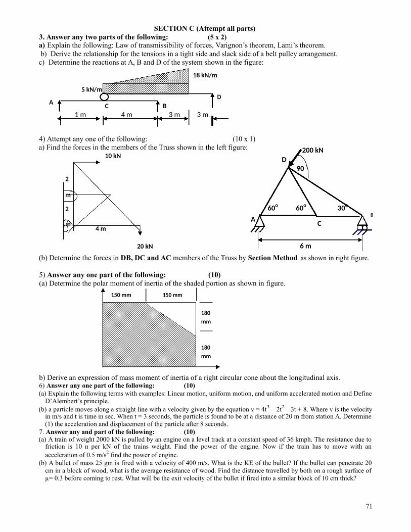
SECTION C (Attempt all parts)3. Answer any two parts of the following: (5 x 2)a) Explain the following: Law of transmissibility of forces, Varignon’s theorem, Lami’s theorem.b) Derive the relationship for the tensions in a tight side and slack side of a belt pulley arrangement.
c) Determine the reactions at A, B and D of the system shown in the figure:
18 kN/m
5 kN/m
AD
C B1 m 4 m 3 m 3 m
4) Attempt any one of the following: (10 x 1)a) Find the forces in the members of the Truss shown in the left figure:
10 kN200 kN
D90
2
m
2 60o 60o 30o
AB
m C4 m
20 kN
(b) Determine the forces in DB, DC and AC members of the Truss by Section Method
5) Answer any one part of the following: (10)(a) Determine the polar moment of inertia of the shaded portion as shown in figure.
6 m
as shown in right figure.
150 mm 150 mm
180mm
180mm
b) Derive an expression of mass moment of inertia of a right circular cone about the longitudinal axis.6) Answer any one part of the following: (10)(a) Explain the following terms with examples: Linear motion, uniform motion, and uniform accelerated motion and Define
D’Alembert’s principle.(b) a particle moves along a straight line with a velocity given by the equation v = 4t3 – 2t2 – 3t + 8. Where v is the velocity
in m/s and t is time in sec. When t = 3 seconds, the particle is found to be at a distance of 20 m from station A. Determine(1) the acceleration and displacement of the particle after 8 seconds.
7. Answer any and part of the following: (10)(a) A train of weight 2000 kN is pulled by an engine on a level track at a constant speed of 36 kmph. The resistance due to
friction is 10 n per kN of the trains weight. Find the power of the engine. Now if the train has to move with anacceleration of 0.5 m/s2 find the power of engine.
(b) A bullet of mass 25 gm is fired with a velocity of 400 m/s. What is the KE of the bullet? If the bullet can penetrate 20cm in a block of wood, what is the average resistance of wood. Find the distance travelled by both on a rough surface ofµ= 0.3 before coming to rest. What will be the exit velocity of the bullet if fired into a similar block of 10 cm thick?
71

B.TECH – MODEL QUESTION PAPER (2) 2013 – 14
SEMESTER –1st YEAR - FIRST SECTION – K to S
SUBJECT – ENGINEERING MECHANICS SUBJECT CODE - ME 101
Time: 3.00 Hours Max Marks : 100Notes: (i) This paper is in three sections. Draw neat sketches to support your answer
(ii) Marks are indicated against each section. Attempt questions from each sectionas per instructions. Assume missing data suitably, if any.
SECTION – A10. Attempt all parts of this question: (2X10 = 20)
q) Discuss the parallelogram law of force addition and polygon law of forces.r) Explain principle of transmissibility of force.s) State and Prove the Varignon’s Principle.t) What do you mean by angle of repose, Limiting friction and coefficient of friction.u) What are the assumptions made in the analysis of a simple truss.v) Differentiate between centroid and centre of gravity.w) Explain transfer formula for determining the MOI.x) Explain Polar moment of inertia & Radius of gyration.y) Explain the difference between kinematics and kinetics.z) Explain the types of motion.
SECTION – B
Note : Attempt any three questions. Each part carry equal marks. (10X3 = 30)a) (i) Determine the magnitude and direction of the resultant of following force system as shown in fig.
12N 10 N
30⁰ 5 N
40⁰ 30⁰
4 N 60⁰40⁰
12 N
15 N 8 N forces as shown in fig. Determine resultant and specify its point(ii) Three cables attached to a disk exert on it
of application on line AD.
140 N C 110 N45⁰ B 20⁰
A
D45⁰
140 N
72
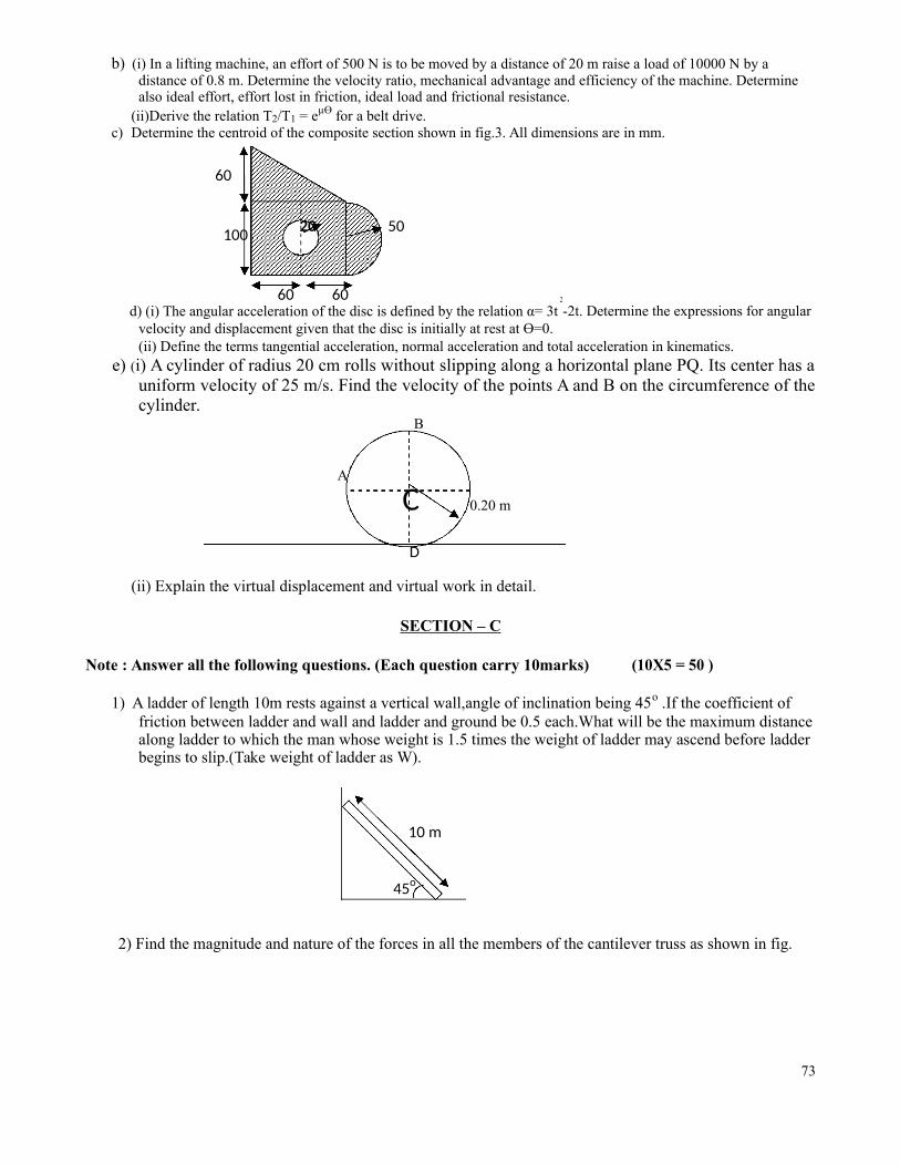
b) (i) In a lifting machine, an effort of 500 N is to be moved by a distance of 20 m raise a load of 10000 N by a distance of 0.8 m. Determine the velocity ratio, mechanical advantage and efficiency of the machine. Determine also ideal effort, effort lost in friction, ideal load and frictional resistance.
(ii)Derive the relation T2/T1 = eµӨ for a belt drive.c) Determine the centroid of the composite section shown in fig.3. All dimensions are in mm.
60
100 20 50
60 60 2
-2t. Determine the expressions for angulard) (i) The angular acceleration of the disc is defined by the relation α= 3tvelocity and displacement given that the disc is initially at rest at Ө=0.(ii) Define the terms tangential acceleration, normal acceleration and total acceleration in kinematics.
e) (i) A cylinder of radius 20 cm rolls without slipping along a horizontal plane PQ. Its center has auniform velocity of 25 m/s. Find the velocity of the points A and B on the circumference of thecylinder.
B
A
C 0.20 m
D
(ii) Explain the virtual displacement and virtual work in detail.
SECTION – C
Note : Answer all the following questions. (Each question carry 10marks) (10X5 = 50 )
1) A ladder of length 10m rests against a vertical wall,angle of inclination being 45o .If the coefficient of friction between ladder and wall and ladder and ground be 0.5 each.What will be the maximum distance along ladder to which the man whose weight is 1.5 times the weight of ladder may ascend before ladder begins to slip.(Take weight of ladder as W).
10 m
45o
2) Find the magnitude and nature of the forces in all the members of the cantilever truss as shown in fig.
73

3) Determine the moment of inertia of the L-section shown in fig .about its centroidal axis. Also determine the radius of gyration with respect to centroidal x – x axis and y – y axis. All dimensions are in “m”.
12
150
10
1204) (i) Derive the expression for mass M.I for a right circular cone of base radius R ,height H and mass M
about its axis of rotation.(ii)Discuss the various forms of Energies.
5) (i) What do you mean by the translational and rotational motion of rigid body?(ii) In the mechanism as shown in fig. (A), determine the horizontal force P required to be applied to holdthe system in equilibrium. The length of each link is L and that of weight is W.
6) Explain the D’Alembert principle, work energy principle and impulse momentum method.A bullet weighs 0.5N and moving with the velocity of 400m/s hits a centrally 30N block of wood moving
away at 15m/s and gets embedded in it. Find the velocity of the bullet after the impact and the amount of kineticenergy lost.
********************************************************
74

B.TECH – MODEL QUESTION PAPER (3) 2013 – 14
SEMESTER –1st YEAR - FIRST SECTION – K to S
SUBJECT – ENGINEERING MECHANICS SUBJECT CODE - ME 101
Time: 3.00 Hours Max Marks : 100
Attempt all questions. Marks are indicated against each question part.(ii) Assume missing data suitably, if any.
Section-A
1. You are required to answer briefly all the parts : 10 × 2 = 20(a) State principle of transmissibility of a force.(b) What is equilibrium? State the necessary and sufficient conditions for a system of coplanar
forces to be in equilibrium.(c) Write down assumptions made in the analysis of truss.(d) Explain the difference between coefficient of friction and angle of friction.(e) Define polar moment of inertia. What is its use ?(f) Differentiate between centroid and centre of gravity.(g) Define tangential, normal and resultant acceleration.(h) Distinguish between relative velocity and resultant velocity.(i) State D’Alembert principle. What is its importance?(j) State the principle of conservation of momentum and give some of its practical
example.
Section-B
2. Answer any three parts of the following : 3 × 10 = 30(a) A 600 N cylinder is supported by the frame BCD as shown in Fig. 2a.The frame is
hinged at D. Determine reactions at A, B, C and D.
D300 mm
600 mm
C A
B30 kN 20 kN
Fig. 2a Fig. 2b
75

Mechanical Engineering Department Date: 06.12.2013Inderprastha Engineering College, Ghaziabad (UP)
(b) Compute the forces in each member of the loaded cantilever truss shown in fig. 2b.Take length of each member 5 m.
102
AY
213
2 1 m 0.4 m
Fig. 2e12 X
Fig. 2c
(c) Determine the centroidal polar moment of inertia of Z-section shown in fig. 2c. All dimensions are in cm.
(d) (i) A motorist enters a curved road with a 90 m radius of curvature with a velocity of 90kmph and reduces the speed uniformly to 60 kmph in 10 s. determine the totalacceleration at the end of 5 seconds.(ii) Two ships move from a port at the same time. Ship A has velocity of 30 kmph andis moving in N 30° W while ship B is moving in south-west direction with a velocity of40 kmph. Determine the relative velocity of A with respect to B and the distancebetween them after half an hour.
(e) A cylinder weighing 500 N is welded to a 1 m uniform bar of 200 N as shown in fig.2e. Determine the acceleration with which the assembly will rotate about point A, ifreleased from rest in horizontal position. Determine reaction at A at this instant.
Section-C3. Answer any two part of the following : 2 × 5 = 10
(a) State and prove Lami’s theorem.120
4080 N
100 N80 40
60°A 30° C 20
120 N30 60 20 50
Fig. 3c Fig. 5a
(b) Classify two dimensional force system with example.(c) Find the resultant of the force system shown in fig. 3c acting on a lamina of equilateral
triangular shape.AC = BC= AB = 100 mm
76

4. Answer any two part of the following : 2 × 5 = 10
(a) A uniform ladder weighing 800 N and 10 m long is resting on a rough horizontal floorand inclined at an angle of 30° with the vertical wall. The ladder would just slip if aman of 100 N weight reaches a point that is 8 m from the lower end of the ladder.If thecoefficient of friction between the wall and the ladder is 0.4, determine the coefficientof friction between the ladder and the floor.
(b) Prove T1/T2 = eμθ
(c) State and prove Varignon’s theorem.
5. Answer any two part of the following : 2 × 5 = 10(a) Determine centroid of shaded area shown in fig . 5a(b) Determine the centroid of a circular sector of radius R and central angle 2α.(c) Derive an expression for the moment of inertia of a cylinder of length L, radius R and density ρ
about its centroidal axes.
6. Answer any two part of the following : 2 × 5 = 10(a) The acceleration of a particle in rectilinear motion is defined by the relation a = 3t2 + 2.
Given that the initial velocity and displacement are respectively 2 m/s and 3 m, writethe equation of motions. Also, determine the position, velocity and acceleration at t=2s.
(b) A flywheel, which accelerate at uniform velocity is observed to have made 100revolution to increase its velocity from 120 rpm to 160 rpm. If the flywheel originallystarted from rest, determine(i) the value of acceleration (ii) time taken to increase the velocity from 120 rpm to 160rpm and (iii) revolution made in reaching a velocity of 160 rpm, starting from rest.
(c) Determine the velocities of the points B and D given in fig. 6 c by instantaneous centre method.Given angular velocity ω = 5 rad/sec, Wheel radius = 1 m.
7. Answer any two part of the following : 2 × 5 = 10(a) Explain principle of work energy and principle of virtual work.(b) Determine the tension in the string and acceleration of blocks A and B weighing
1500N and 500 N connected by an inextensible string as shown in fig. 7b.(c) A ladder having weight 200 N is supported by a smooth wall and a rough floor (μ =
0.3) as shown in figure 7c. The ladder is in equilibrium. Find the friction force at pointB of floor using virtual work method
B
A
A DB B
Fig. 7c A
77

SOLUTION of Assignment on Beam and Truss
Numerical Questions:
A simply supported beam of span 12 m is loaded with a uniformly varying load of 50 kN /m at left end and 110 kN / m at right end. Find reactions at support.
FBD50x12 ½ x (110-50) x 12
6 4RBRA
∑Fx Not applicable
∑Fy RA + RB = 50x12 + ½ (60x12) = 960 ------ (1)
∑MA RB x 12 = 600 x 6 + 360 x 8; RB = 540 kN and from (1) so RA = 420 kNFor checking RA x 12 = 600 x 6 + 360 x 4the answer RA = 420 kN∑MB
Answer RA= 420 kN ; RB = 540 kN
Find reactions at support for the following beam .
50 kN / m
3 m 6 m
FBD 50x9
RA4.5 RB
∑Fx Not applicable∑Fy RA + RB = 50x9 + 450 ------ (1)∑MA RB x 6 = 450 x 1.5; RB = 112.5 kN and from (1) so RA = 337.5 kNFor checking RA x 6 = 600 x 4.5the answer RA = 337.5 kN∑MB
Answer RA= 337.5 kN ; RB = 112.5 kN
78

Find reactions at support for the following beam.
40 k N30 k N
50 k N / m 20 k N / m
5 m 2 m 1 m 3 m
FBD
50x5= 250 30 k N 40 k N 20x3= 60
RA RB
∑Fx Not applicable∑Fy RA + RB = 250 + 30 + 40 + 60 = 380 ------ (1)∑MA RB x 11 = 250 x 2.5 + 30 x 5 + 40 x 7 + 60 x 9.5;
RB = 1625 / 11 = 147.72 kN and from (1) so RA = 232.28 kNFor checking RA x 11 = 250 x 8.5 + 30 x 6 + 40 x 4 + 60 x 1.5the answer RA = 232.28 kN∑MB
Answer RA= 232.28 kN ; RB = 147.72 kN
Find reactions at the fixed support for the following beam.
80 k N100 k N
40 k N / m
4 m 4 m
FBD40x8= 320
100 k N
80 k N
MA
RAV
∑Fx Not applicable∑Fy RAV = 80 + 320 +100 = 500 kN ------ (1)∑MA MA = (80 + 320) x 4 + 100 x 8 = 2400 kN-m anticlockwiseAnswer RAV= 500 kN ; MA = 2400 kN-m anticlockwise
79

Determine the forces in all the members of the Truss by Joint Method as shown in figure.
100 kN
D 90 600
RAH 60o 60o 30o
A BC
8 mRAV RB
Considering all members as compressive
Reactions at support∑Fx RAH = 100 cos 60 = 50 ------ (1)Not applicable∑Fy RAV + RB = 100 sin60 = 86.60 ------ (1)∑MA RB x 8 = 0 hence RB = 0; RAV = 86.60At Joint A ∑Fx = 0 ∑Fy = 0
FAC + FAD cos 60 = RAH i.e 50 FAD sin60 = RAV i.e 86.60FAC = 50 - FAD cos 60 FAD = 86.60 / sin60 = 100 kN (Comp.)FAC = 50 - 100 cos 60 = 0 (NullMember)
At Joint B ∑Fx = 0 ∑Fy = 0FBC + FBD cos 30 = 0 FBD sin30 = 0FBC = 0 – FBD cos 30 FBD = 0 (Null)FBC = 0 - 0 = 0 (Null Member)
At Joint C - ∑Fy = 0FCD sin60 = 0FCD = 0 (Null)
Answer FAC = 0 (Null Member) FBD = 0 (Null member)FAD = 100 kN (Comp.) FCD = 0 (Null member)FBC = 0 (Null Member)
80

Determine the forces in the members of the truss by Methods of Section, shown in figure.
DE, AE, AB and FE, FB and BC
12
D 50 kN E 80 kN F
0 60 0 60
A 12 m B 12 m C
60 kN 2 100 kN
1
SECTION 1-1 and taking Right Hand Side Section∑Fx FDE + FAE cos 60 + FAB = 0 ---- (1)∑Fy FAE sin 60 = 50 + 80 + 60 +100 = 290 / sin 60; FAE = 334.86 kN ------ (2)
∑ME FAB x 6√3 = 60 x 6 + 80 x 12 + 100 x 18 ; FAB = 265.68 kN ---- (3)
From (1), (2) and (3)FDE = - 433.11 kN i.e 433.11 (Tensile)FAE = 334.86 kN (Comp.)FAB = 265.68 kN (Comp.)
Answer FDE = 433.11 (Tensile) FAB = 265.68 kN (Comp.)FAE = 334.86 kN (Comp.)
SECTION 2-2 and taking Right Hand Side Section∑Fx FEF + FBF cos 60 + FBC = 0 ---- (1)∑Fy FBF sin 60 = 80 +100 = 180 / sin 60; FAE = 207.84 kN ------ (2)
∑MF FBC x 6√3 = 100 x 6 ; FBC = 57.73 kN ---- (3)
From (1), (2) and (3)FEF = -161.65 kN i.e 161.65 (Tensile)
Answer FEF = 161.65 (Tensile) FBC = 57.73 kN (Comp.)FAE = 207.84 kN (Comp.)
81