Embed Size (px)
Citation preview

www.allsyllabus.com
www.allsyllabus.com
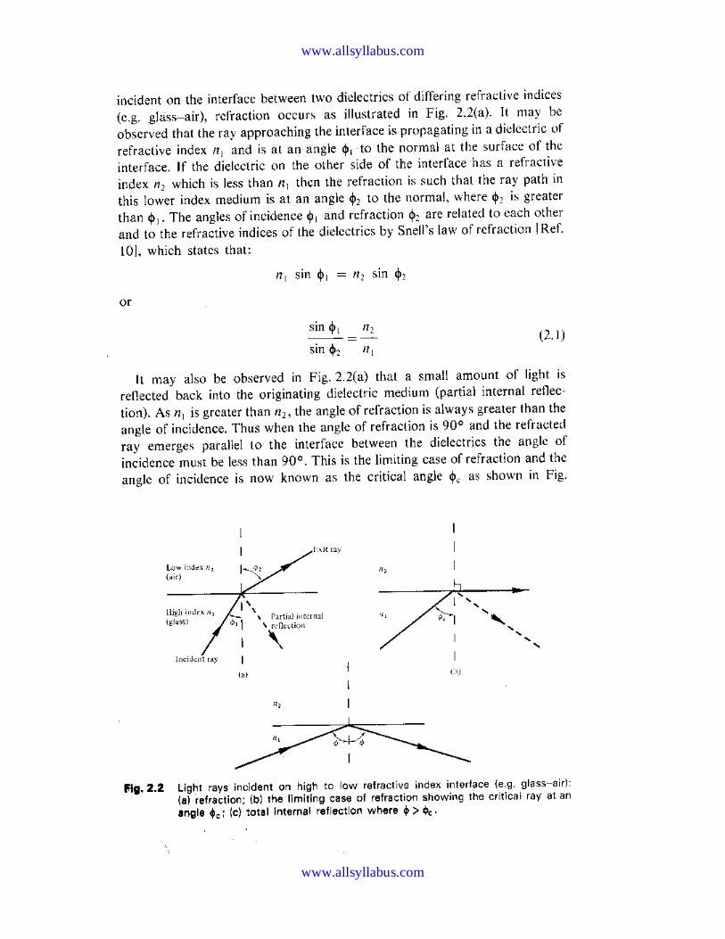
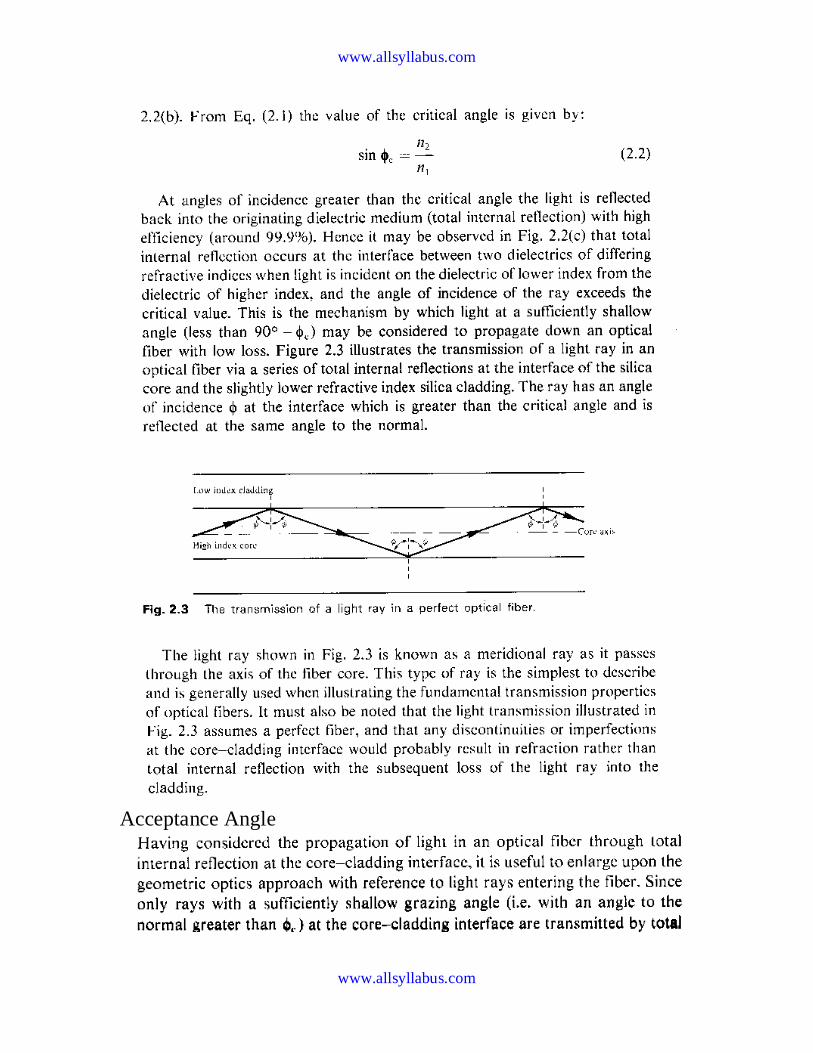
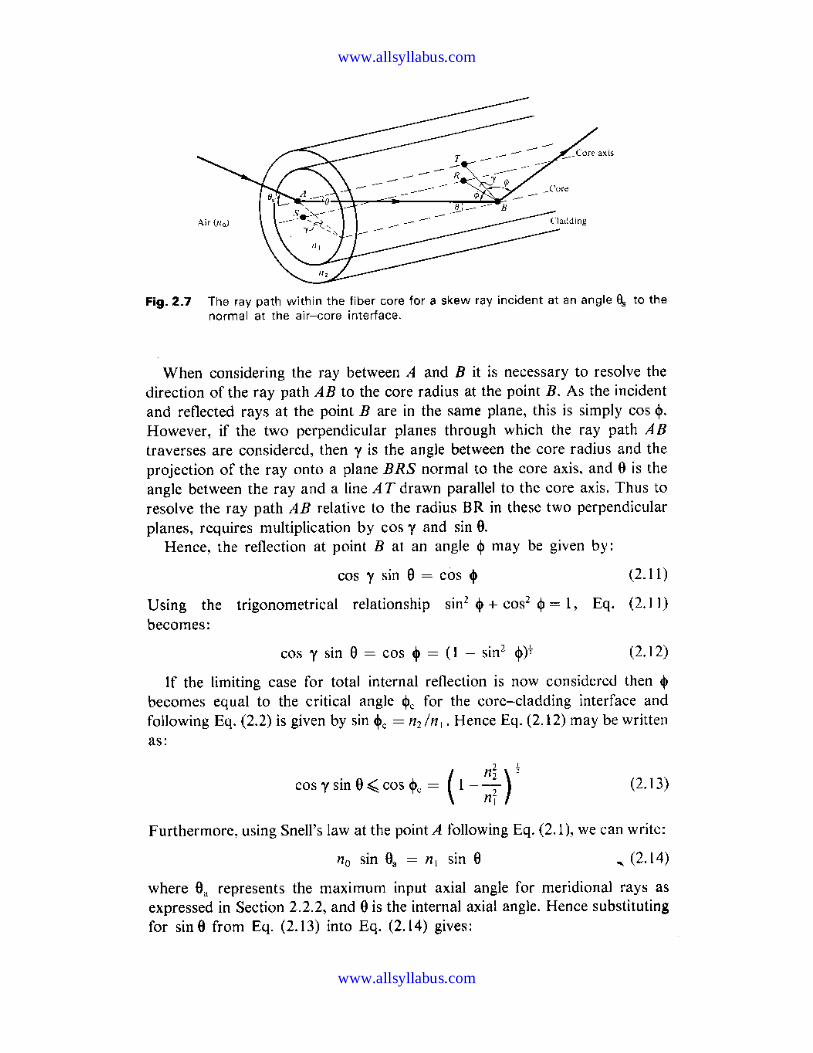
Ray theory transmission
Total internal reflection

www.allsyllabus.com
www.allsyllabus.com
Electromagnetic mode theory for optical propagation
EM Waves

www.allsyllabus.com
www.allsyllabus.com
Unit-2
Transmission characteristics of optical fibers Attenuation

www.allsyllabus.com
www.allsyllabus.com
Material Absorption losses
Intrinsic absorption

www.allsyllabus.com
www.allsyllabus.com
Mie Scattering
Non-linear scattering losses

www.allsyllabus.com
www.allsyllabus.com
Stimulated brillouin scattering
Stimulated Raman scattering

www.allsyllabus.com
www.allsyllabus.com
Intramodal or chromatic dispersion
Intermodal dispersion
www.allsyllabus.com
www.allsyllabus.com
Unit 3
Optical sources & detectors
semiconductor injection laser

www.allsyllabus.com
www.allsyllabus.com
High impedance front end
FET preamplifiers

www.allsyllabus.com
www.allsyllabus.com
Unit-5
SONET/SDH
The SONET/SDH Digital Hierarchy
The basic foundation of SONET consists of groups of DS-0 signals
(64Kbits/sec) that are multiplexed to create a 51.84Mbit/sec signal, which is
also known as STS-1 (Synchronous Transport Signal). STS-1 is an electrical signal rate that corresponds to the Optical Carrier line rate of OC-1,
SONET's building block. Subsequent SONET rates are created by
interleaving (at the byte level) STS-1 signals to create a concatenated, or linked, signal. For example, three STS-1 frames can form an STS-3 frame
(155Mbits/sec). Rates above STS-3 can be created by either directly
multiplexing STS-1 signals or by byte-interleaving STS-3 signals. The
following table lists the hierarchy of the most common SONET/SDH data rates:

www.allsyllabus.com
www.allsyllabus.com
Optical Level
Electrical Level
Line Rate (Mbps)
Payload Rate (Mbps)
Overhead Rate (Mbps)
SDH Equivalent
OC-1 STS-1 51.840 50.112 1.728 -
OC-3 STS-3 155.520 150.336 5.184 STM-1
OC-12 STS-12 622.080 601.344 20.736 STM-4
OC-48 STS-48 2488.320 2405.376 82.944 STM-16
OC-192 STS-192 9953.280 9621.504 331.776 STM-64
OC-768 STS-768 39813.120 38486.016 1327.104 STM-256
The "line rate" refers to the raw bit rate carried over the optical fiber. A portion of the bits transferred over the line are designated as "overhead". The
overhead carries information that provides OAM&P (Operations,
Administration, Maintenance, and Provisioning) capabilities such as
framing, multiplexing, status, trace, and performance monitoring. The "line rate" minus the "overhead rate" yields the "payload rate" which is the
bandwidth available for transferring user data such as packets or ATM cells.
The SONET/SDH level designations sometimes include a "c" suffix (such as "OC-48c"). The "c" suffix indicates a "concatenated" or "clear" channel.
This implies that the entire payload rate is available as a single channel of
communications (i.e. the entire payload rate may be used by a single flow of cells or packets). The opposite of concatenated or clear channel is
"channelized". In a channelized link the payload rate is subdivided into
multiple fixed rate channels. For example, the payload of an OC-48 link may
be subdivided into four OC-12 channels. In this case the data rate of a single cell or packet flow is limited by the bandwidth of an individual channel.
Protocol Layers
The SONET/SDH standard includes a definition of a transmission protocol stack which solves the operation and maintenance problems often found
when dealing with networks that have component streams lacking a common
clock.
The photonic layer is the electrical and optical interface for transporting
information over fiber optic cabling. It converts STS electrical signals into
optical light pulses (and vice versa, at the receiving end). The section layer

www.allsyllabus.com
www.allsyllabus.com
transports STS frames over optical cabling. This layer is commonly
compared with the Data-Link layer of the OSI model, which also handles framing and physical transfer.
The line layer takes care of a number of functions, including synchronization
and multiplexing for the path layer above it. It also provides automatic protection switching, which uses provisioned spare capacity in the event of a
failure on the primary circuit.
The highest level, the path layer, takes services such as DS-3, T1, or ISDN
and maps them into the SONET/SDH format. This layer, which can be accessed only by equipment like an add/drop multiplexer (a device that
breaks down a SONET/SDH line into its component parts), takes care of all
end-to-end communications, maintenance, and control.
Topology
SONET/SDH supports several topologies, including point to point, a hub
and spoke star configuration, and the ring topology. The ring topology, which is by far the most popular, has been used for years by such network
technologies as FDDI and Token Ring and has proven quite robust and fault-
tolerant. A SONET/SDH ring can contain two pairs of transmit and receive fibers. One pair can be designated as active with the other one functioning as
a secondary in case of failure. SONET/SDH rings have a "self-healing"
feature that makes them even more appealing for long distance connections
from one end of the country to another.
One of SONET/SDH's most interesting characteristics is its support for a
ring topology. Normally, one piece of fiber -- the working ring -- handles all
data traffic, but a second piece of fiber -- the protection ring remains on standby. Should the working ring fail, SONET/SDH includes the capability
to automatically detect the failure and transfer control to the protection ring
in a very short period of time, often in a fraction of a second. For this reason,
SONET/SDH can be described as a self-healing network technology.
Rings normally will help SONET/SDH service to reach the "five nines"
availability level. However, the usefulness of rings also depends on their
physical location. If the rings are located next to each other, then if a back-hoe from a construction company takes out one of your fibers, it is quite
likely that the second one will go as well. Thus, your rings should be

www.allsyllabus.com
www.allsyllabus.com
physically separated from each other as much as possible in order to achieve
high uptime.
Broadcast And Select WDM networks
It shares a common transmission medium and employs a single broadcasting mechanism for transmitting and receiving optical signals.
The most popular topology is the star and bus topology
In star topology, a no. of nodes connected a passive star coupler.
In bus topology a no. of nodes connected to a bus through 2*2 couplers by
WDM fiber links.
Wavelength routed WDM network
It is a circuit switched network in which a pair of network nodes
communicates through an end to end optical connection that may consists of
light paths.
Solitons
A single, consensus definition of a soliton is difficult to find. Drazin &
Johnson (1989, p. 15) ascribe three properties to solitons:
1. They are of permanent form;
2. They are localised within a region;
3. They can interact with other solitons, and emerge from the collision
unchanged, except for a phase shift.
More formal definitions exist, but they require substantial mathematics.
Moreover, some scientists use the term soliton for phenomena that do not
quite have these three properties (for instance, the 'light bullets' of nonlinear
optics are often called solitons despite losing energy during interaction).
Dispersion and non-linearity can interact to produce permanent and localized
wave forms. Consider a pulse of light traveling in glass. This pulse can be

www.allsyllabus.com
www.allsyllabus.com
thought of as consisting of light of several different frequencies. Since glass
shows dispersion, these different frequencies will travel at different speeds
and the shape of the pulse will therefore change over time. However, there is
also the non-linear Kerr effect: the refractive index of a material at a given
frequency depends on the light's amplitude or strength. If the pulse has just
the right shape, the Kerr effect will exactly cancel the dispersion effect, and
the pulse's shape won't change over time: a soliton. See soliton (optics) for a
more detailed description.
Many exactly solvable models have soliton solutions, including
the Korteweg–de Vries equation, the nonlinear Schrödinger equation, the
coupled nonlinear Schrödinger equation, and the sine-Gordon equation. The
soliton solutions are typically obtained by means of theinverse scattering
transform and owe their stability to the integrability of the field equations.
The mathematical theory of these equations is a broad and very active field
of mathematical research.
Some types of tidal bore, a wave phenomenon of a few rivers including
the River Severn, are 'undular': a wavefront followed by a train of solitons.
Other solitons occur as the undersea internal waves, initiated by
seabed topography, that propagate on the oceanic pycnocline. Atmospheric
solitons also exist, such as the Morning Glory Cloud of the Gulf of
Carpentaria, where pressure solitons travelling in atemperature
inversion layer produce vast linear roll clouds. The recent and not widely
accepted soliton model in neuroscience proposes to explain the signal
conduction within neurons as pressure solitons.
A topological soliton, also called a topological defect, is any solution of a set
of partial differential equations that is stable against decay to the "trivial
solution." Soliton stability is due to topological constraints, rather
than integrability of the field equations. The constraints arise almost always
because the differential equations must obey a set of boundary conditions,
and the boundary has a non-trivialhomotopy group, preserved by the
differential equations. Thus, the differential equation solutions can be
classified into homotopy classes. There is no continuous transformation that
will map a solution in one homotopy class to another. The solutions are truly
distinct, and maintain their integrity, even in the face of extremely powerful
forces. Examples of topological solitons include the screw dislocationin

www.allsyllabus.com
www.allsyllabus.com
a crystalline lattice, the Dirac string and the magnetic
monopole in electromagnetism, the Skyrmion and the Wess–Zumino–Witten
model in quantum field theory, and cosmic strings and domain
walls in cosmology.