Embed Size (px)
Citation preview
Notes on Electrode Evaporation
Jeff Elam, Argonne
MCP Coating Fixture for Electrode Evaporation
These slides show a fixture that Joe Libera and Qing Peng designed and fabricated to hold three Incom glass substrates (33 mm OD, 8° bias angle) during the nichrome electrode evaporation. The substrates are oriented such that the top of each pore is tilted towards the center of the fixture. Next, they are dropped into a cup which is tilted outwards at -8° so the pores end up vertically aligned. This arrangement will allow us to control the end spoiling.
2

MCP Coating Fixture for Electrode Evaporation
3

MCP Coating Fixture for Electrode Evaporation
4

bias angle aligned with center post:Pores now point straight into page and text is visible
bias angle misaligned:Pores now point diagonally into page and text is blurry
Fixture is shown loaded with one Incom glass plate in lower opening. When rotation angle of plate is properly aligned, the text below is clear. Otherwise, it is blurry Red dot marks the inclination direction of the 8° bias angle pores. This demonstrates that the fixture holds the plates at the appropriate orientation for controlling the end spoiling during evaporation.
5
nichromeevaporation
source
θ=45°
L1=L2, ≥12”
L1
L2
rotate
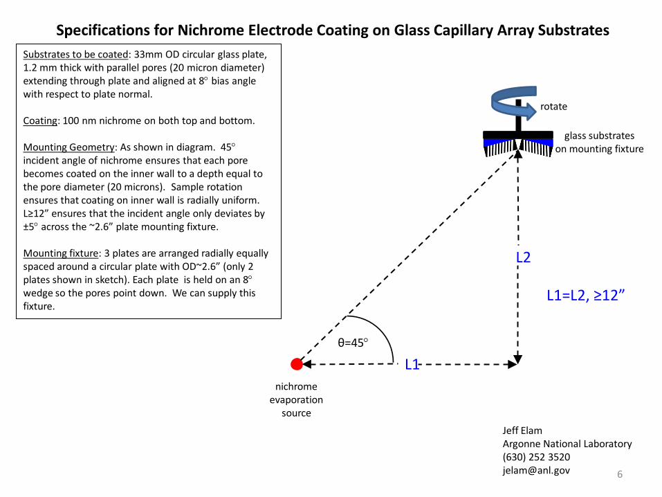
Substrates to be coated: 33mm OD circular glass plate, 1.2 mm thick with parallel pores (20 micron diameter) extending through plate and aligned at 8° bias angle with respect to plate normal.
Coating: 100 nm nichrome on both top and bottom.
Mounting Geometry: As shown in diagram. 45°incident angle of nichrome ensures that each pore becomes coated on the inner wall to a depth equal to the pore diameter (20 microns). Sample rotation ensures that coating on inner wall is radially uniform. L≥12” ensures that the incident angle only deviates by ±5° across the ~2.6” plate mounting fixture.
Mounting fixture: 3 plates are arranged radially equally spaced around a circular plate with OD~2.6” (only 2 plates shown in sketch). Each plate is held on an 8°wedge so the pores point down. We can supply this fixture.
Specifications for Nichrome Electrode Coating on Glass Capillary Array Substrates
glass substrateson mounting fixture
Jeff ElamArgonne National Laboratory(630) 252 [email protected] 6
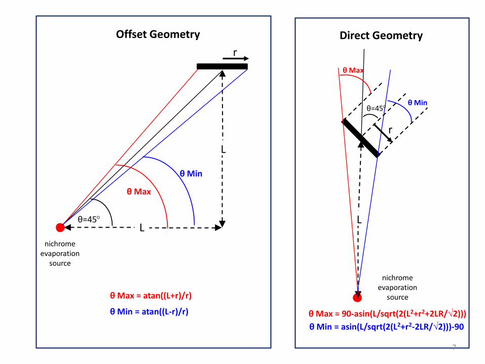
Offset Geometry
nichromeevaporation
source
θ Min
L
L
θ=45°
θ Max
Direct Geometry
nichromeevaporation
source
θ Min
L
θ=45°
θ Max
r
r
θ Max = atan((L+r)/r)
θ Min = atan((L-r)/r) θ Max = 90-asin(L/sqrt(2(L2+r2+2LR/√2)))θ Min = asin(L/sqrt(2(L2+r2-2LR/√2)))-90
7

30
35
40
45
50
55
60
0 200 400 600 800 1000 1200
Direct MaxDirect MinOffset MaxOffset min
Inci
dent
Ang
le o
f Eva
pora
ted
Ato
ms
(deg
rees
)
Distance to Source (L, mm)
Assume 3x 33mm plates(r=44.5 mm max radius)
For ±5°, 3x33 mm (r=44.5)
Direct: L=400 mm (16”)Offset: L=275 mm (11”)
For ±5°, 1x8” plate (r=145 mm)
Direct: L=1300mm (52”)Offset: L=914 mm (36”)
8