Embed Size (px)
Citation preview

8/20/2019 notes on powerplant.pdf
http://slidepdf.com/reader/full/notes-on-powerplantpdf 1/202
8/20/2019 notes on powerplant.pdf
http://slidepdf.com/reader/full/notes-on-powerplantpdf 2/202
8/20/2019 notes on powerplant.pdf
http://slidepdf.com/reader/full/notes-on-powerplantpdf 3/202
8/20/2019 notes on powerplant.pdf
http://slidepdf.com/reader/full/notes-on-powerplantpdf 4/202
8/20/2019 notes on powerplant.pdf
http://slidepdf.com/reader/full/notes-on-powerplantpdf 5/202

8/20/2019 notes on powerplant.pdf
http://slidepdf.com/reader/full/notes-on-powerplantpdf 6/202
8/20/2019 notes on powerplant.pdf
http://slidepdf.com/reader/full/notes-on-powerplantpdf 7/202
NOTES
ON
POWER
PLANT
DESIGN
PREPARED
FOR
THE
USE
OF STUDENTS
IN
THE
MECHANICAL
ENGINEERING
DEPARTMENT
OF
THE
MASSACHUSETTS
INSTITUTE
OF
TECHNOLOGY
EDWARD F.
MILLER
\
\
1915
8/20/2019 notes on powerplant.pdf
http://slidepdf.com/reader/full/notes-on-powerplantpdf 8/202
COPYRIGHT,
1916
BY
EDWARD
F.
MILLER
8/20/2019 notes on powerplant.pdf
http://slidepdf.com/reader/full/notes-on-powerplantpdf 9/202
INTRODUCTION
An
attempt
has been made to
assemble
here,
in
condensed
form,
data
which
it
is believed
will
be
of
assistance to one
beginning
on the
laying
out
of
a
power plant.
Some
of
the
material
has
been
taken
from
articles
which
have
appeared
either in
the Trans-
actions
of
the
American
Society
of
Mechanical
Engineers
or
in
the
engineering periodicals.
Abstracts
have
also
been
made from
Gebhardt's Steam
Power
Plant
Engineering,
from
Koester's
Steam
Electric
Power
Plants,
from
Peabody
and
Miller's Steam
Boilers,
from Illustrations
of
Steam
Engines,
Steam
Turbines,
etc.,
from
trade
catalogues
and
from
publications
gotten
out
by
manufacturers
of
the
different
pieces
of
apparatus
which
enter
into
the
equipment
of a
power
plant.
E.
F.
M.
8/20/2019 notes on powerplant.pdf
http://slidepdf.com/reader/full/notes-on-powerplantpdf 10/202
TABLE
OF CONTENTS
DISTRIBUTION
OF HEAT
5,
6
BOILERS
7-15
Methods of
supporting;
dimensions
of;
flues
for;
using
fuel
oil;
stack for
boilers
using
fuel
oil.
ECONOMIZERS
16-23
Calculation
of
size
of;
tables of
dimensions
of.
MECHANICAL
STOKERS
24-25
CHIMNEYS,
FLUES
AND
DRAUGHT
26-29
FEED
PUMPS
VENTURI
METER
29-33
ENGINES
34-49
Steam
Consumption
of;
calculation of
power of;
cylinder efficiency
of
steam
engines
and steam
turbines;
Rankine
efficiency
and
cylinder efficiency;
calculation
of bleeder
type
of
engine
or
turbine;
bleeding steam;
comparison
of
engines
and
turbines
and
water
rate
of
small tur-
bines; general
dimensions
of and
floor
space required
by engines.
CONDENSERS AND
ACCESSORIES
50-68
Surface; jet;
air
pumps;
dry
air
pumps;
circulating pumps;
exhaust relief
valves.
FLOW
OF
STEAM
IN PIPES
69-71
FEED
WATER
HEATERS
72-75
COOLING
TOWERS
76-80
Calculation
of; power
required
by fan;
extra
work
put
on
circulating
pump.
SPRAY NOZZLES
80-81
CENTRIFUGAL
PUMPS
82-90
Characteristics
of;
friction of
water in
pipes.
COAL
HANDLING
AND
COAL
BUNKERS 91-106
Pivoted
bucket
conveyors;
belt
conveyors, scraper
conveyor;
power
required;
crushers;
parabolic
bins.
FOUNDATIONS,
CONCRETE
FLOORS,
WALLS
106-125
COSTS
126-139
Cost
of various
items
entering
into
power
house
construction
and into
equipment
of
power
house;
cost
of
operation
and distribution
of
operating
costs;
failure to make
guarantees
as
to
performance
as
affecting
cost.
PIPING
AND
PIPE
FITTINGS
140-156
Dimensions
of
fittings;
list
price
and
discounts;
cast iron
pipe
for water
work.
PIPE
COVERING
157-159
Cost
of;
insulating
value
of
different
thickness
of; covering
for
flues
and for boiler drums,
SPECIFICATIONS
160-178
Surface
condenser;
hot
well
pump;
dry
vacuum
pump;
low
pressure
turbine;
direct
acting
boiler
feed
pump;
automatic
pump
and
receiver;
horizontal
cross
compound non-condensing
Cor-
liss
engine;
steam
driven
centrifugal pumping
unit;
motor
driven
centrifugal pumping
unit.
CUTS
OF
STATIONS ,
*
179-185
8/20/2019 notes on powerplant.pdf
http://slidepdf.com/reader/full/notes-on-powerplantpdf 11/202
DISTRIBUTION
OF HEAT
It
is
generally
known that
but a small
proportion
of the heat of the
coal burned in a
power
plant goes
into
power.
In cases where there
is a
large
demand
for steam
for
heating
during
eight
months of
the
year
the exhaust
steam
from
the
engines
or turbines
used for
power
or
lights
may
be
saved
by
utilizing
this steam
in the
heating
system.
Under
such
conditions
the
cost
of
power
for
the
period
of
heating
is low
and
during
this
period
the
economy
of the
engine
is
of
little
moment
provided
there
is
never
a
surplus
of
exhaust
steam.
During
the
remaining
four
months
when
no
heat
is
required,
the
economy
of the
engine
is
of
importance.
Under
all
conditions the
efficiency
of the boiler
affects
the cost
of
operation.
The
distribution
of heat
throughout
a
plant
may
be
illustrated
by
the
two
cases
worked
out
below.
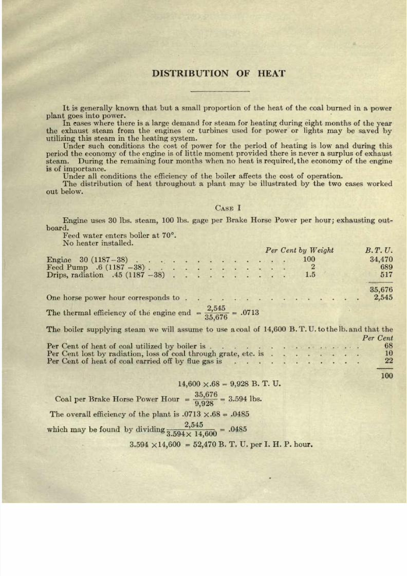
CASE
I
Engine
uses 30 Ibs.
steam,
100 Ibs.
gage
per
Brake
Horse Power
per hour;
exhausting
out-
board.
Feed water
enters
boiler at 70.
No
heater
installed.
Per Cent
by Weight
B. T.
U.
Engine
30
(1187-38)
...........
.
. .
100
34,470
Feed
Pump
.6
(1187 -38)
............
2
689
Drips,
radiation .45
(1187
-38)
........
. .
1.5
517
35,676
One
horse
power
hour
corresponds
to
..... ..........
2,545
2
545
The
thermal
efficiency
of the
engine
end
=
^
r
=
.0713
o5,b7o
The
boiler
supplying
steam we will
assume to
use a coal
of
14,600
B.T.
U.tothelb.
and
that the
Per
Cent
Per Cent of
heat
of
coal
utilized
by
boiler
is
..........
.......
68
Per
Cent lost
by
radiation,
loss of
coal
through
grate,
etc. is ........
10
Per
Cent
of heat of
coal
carried
off
by
flue
gas
is ...........
22
100
14,600
x.68
=
9,928
B. T.
U.
or
Coal
per
Brake
Horse Power Hour
=
--SO-
=
3.594 Ibs.
The overall
efficiency
of the
plant
is
.0713
x.68
=
.0485
2
545
y
dividing
3
594^
14500
=
'
485
3.594
x
14,600
=
52,470
B.
T.
U.
per
I.
H.
P.
hour.
2
545
which
may
be
found
by
dividing
3
594^
14500
=
'
485
8/20/2019 notes on powerplant.pdf
http://slidepdf.com/reader/full/notes-on-powerplantpdf 12/202
NOTES
ON
POWER
PLANT
DESIGN
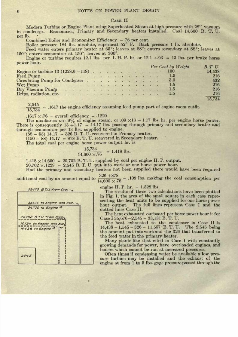
CASE
n
Modern
Turbine
or
Engine
Plant
using
Superheated
Steam at
high
pressure
with 28
vacuum
in
condenser.
Economizer,
Primary
and
Secondary
heaters
installed. Coal
14,600
B.
T.
U.
Der
Ib.
Combined
Boiler
and
Economizer
Efficiency
=
76
per
cent.
Boiler
pressure
184
Ibs.
absolute, superheat
52
F.
Back
pressure
1 Ib.
absolute.
Feed
water
enters
primary
heater at
65;
leaves at
88;
enters
secondary
at
88;
leaves
at
150;
enters
economizer
at
150;
leaves
at
300.
Engine
or
turbine
requires
12.1
Ibs.
per
I.
H. P. hr. or
12.1
-=-.93
=
13
Ibs.
per
brake
horse
power
hour.
Per Cent
by Weight
Engine
or
turbine
13
(1228.6
-118)
Feed
Pump
Circulating
Pump
for
Condenser
.
Wet
Pump
Dry
Vacuum
Pump
....
Drips,
radiation,
etc
100
1.5
3.0
1.5
1.5
1.5
B.T.U.
14,438
216
432
216
216
216
15,734
2
545
r
=
.1617
the
engine
efficiency
assuming
feed
pump
part
of
engine
room
outfit.
15,734
.1617
x.
76
=
overall
efficiency
=
.1229
The auxiliaries
use
9%
of
engine
steam,
or
.09
x 3
=1.17
Ibs. hr.
per
engine
horse
power.
There
is
consequently
13
+1.17
=
14.17
Ibs.
passing
through primary
and
secondary
heater
and
through
economizer
per
13 Ibs.
supplied
to
engine.
(88
-
65)
14.17
=
326
B. T.
U.
recovered
in
Primary
heater.
(150
-
88)
14.17
=
878
B.
T.
U.
recovered
in
Secondary
heater.
The
total
coal
per
engine
horse
power
output
hr.'is
15,734
=
1.418
Ibs.
14,600
x.76
1.418
x
14,600
=
20,702
B.
T.
U.
supplied
by
coal
per engine
H.
P.
output.
20,702
x.l
229
=
2,545
B.
T. U.
put
into
work
or
one
horse
power
hour.
Had
the
primary
and
secondary
heaters
not been
supplied
there
would
have
been
required
additional coal
by
an
amount
equal
to
=
-109
Ibs.
making
the
coal
consumption
per
5247O
B.TU
from
Coal
35676
-f-o
Engine
and
Aux.
-^
8/20/2019 notes on powerplant.pdf
http://slidepdf.com/reader/full/notes-on-powerplantpdf 13/202
NOTES ON
POWER
PLANT
DESIGN
7
turbine
and
additional
power amounting
to
from
50 to
80
per
cent
of
the
engine
power
obtained
from the
exhaust steam.
In
general
an
engine
designed
to
run
non-condensing
is
not made
sufficiently
strong
and
the
bearing
surfaces
are
not
large
enough
to stand
the
extra
load
brought
to
the
parts
when
the
engine
is
run
condensing.
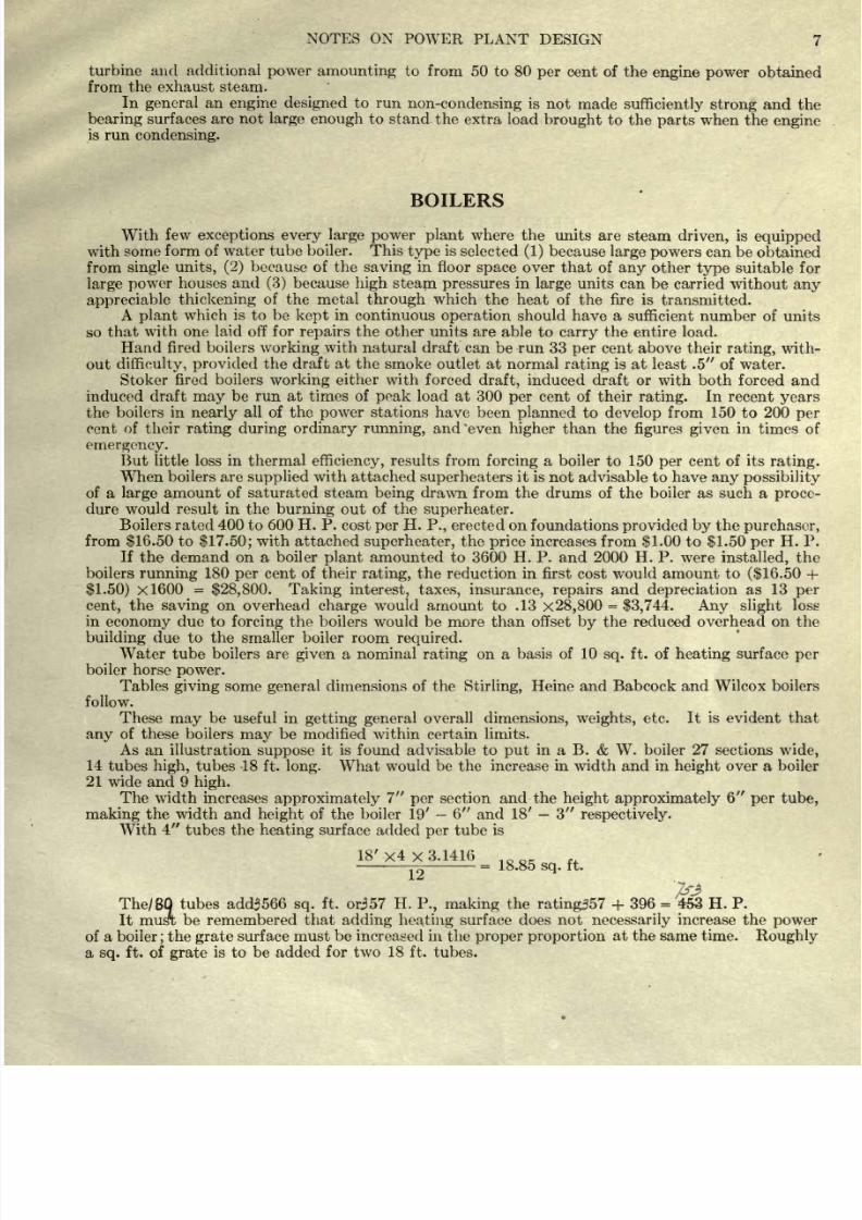
BOILERS
With
few
exceptions every large
power plant
where
the
units
are
steam
driven,
is
equipped
with
some
form
of water
tube boiler.
This
type
is
selected
(1)
because
large
powers
can be
obtained
from
single
units, (2)
because
of the
saving
in
floor
space
over
that
of
any
other
type
suitable
for
large
power
houses
and
(3)
because
high
steam
pressures
in
large
units can
be
carried
without
any
appreciable
thickening
of
the
metal
through
which
the
heat
of
the
fire
is
transmitted.
A
plant
which
is
to
be
kept
in continuous
operation
should have a
sufficient
number
of
units
so
that
with
one
laid off
for
repairs
the other units
are able
to
carry
the
entire
load.
Hand fired boilers
working
with
natural
draft
can be run 33
per
cent
above
their
rating,
with-
out
difficulty,
provided
the
draft
at
the
smoke outlet
at normal
rating
is
at
least .5
of water.
Stoker
fired boilers
working
either
with forced
draft,
induced draft
or
with both
forced
and
induced
draft
may
be
run at times
of
peak
load
at
300
per
cent of
their
rating.
In
recent
years
the
boilers
in
nearly
all
of
the
power
stations
have
been
planned
to
develop
from
150
to
200
per
cent
of
their
rating
during
ordinary
running,
and
'even
higher
than
the
figures given
in
times
of
emergency.
But
little loss in thermal
efficiency,
results
from
forcing
a
boiler
to 150
per
cent of its
rating.
When
boilers are
supplied
with attached
superheaters
it is
not advisable
to have
any
possibility
of a
large
amount of saturated steam
being
drawn from the drums of the
boiler
as
such a
proce-
dure would result
in
the
burning
out
of
the
superheater.
Boilers rated
400
to
600 H. P.
cost
per
H.
P.,
erected
on
foundations
provided
by
the
purchaser,
from
$16.50
to
$17.50;
with attached
superheater,
the
price
increases from
$1.00
to
$1.50
per
H.
P.
If
the
demand
on a
boiler
plant
amounted to 3600 H. P. and
2000
H.
P.
were
installed,
the
boilers
running
180
per
cent
of
their
rating,
the reduction in first cost
would
amount to
($16.50
+
$1.50)
x 600
=
$28,800. Taking interest,
taxes, insurance, repairs
and
depreciation
as
13
per
cent,
the
saving
on
overhead
charge
would
amount
to
.13
x
28,800
=
$3,744.
Any
slight
loss
in
economy
due to
forcing
the
boilers
would
be
more
than offset
by
the
reduced
overhead
on
the
building
due
to
the smaller
boiler
room
required.
Water
tube
boilers
are
given
a
nominal
rating
on
a
basis
of
10
sq.
ft.
of
heating
surface
per
boiler
horse
power.
Tables
giving
some
general
dimensions
of
the
Stirling,
Heine
and
Babcock
and Wilcox
boilers
follow.
These
may
be useful
in
getting
general
overall
dimensions,
weights,
etc.
It
is
evident
that
any
of these
boilers
may
be
modified
within
certain
limits.
As
an
illustration
suppose
it
is
found
advisable to
put
in a
B.
&
W. boiler
27
sections
wide,
14
tubes
high,
tubes
18
ft.
long.
What would
be
the increase
in width and in
height
over a boiler
21
wide and 9
high.
The width
increases
approximately
7
per
section
and
the
height
approximately
6
per
tube,
making
the width and
height
of the
boiler 19'
-
6
and
18'
3
respectively.
With
4
tubes
the
heating
surface
added
per
tube
is
18'
x4 x
3.1416
-^
-
=
18.85
sq.
ft.
I _
7&
The/
80
tubes
add3566
sq.
ft.
orj57
H.
P., making
the
rating357
+
396
=
453 H.
P.
It
musri be
remembered that
adding
heating
surface does not
necessarily
increase
the
power
of a
boiler;
the
grate
surface
must
be increased in the
proper
proportion
at
the
same time.
Roughly
a
sq.
ft.
of
grate
is
to
be added
for
two 18 ft.
tubes.
8/20/2019 notes on powerplant.pdf
http://slidepdf.com/reader/full/notes-on-powerplantpdf 14/202
8
NOTES ON
POWER
PLANT
DESIGN
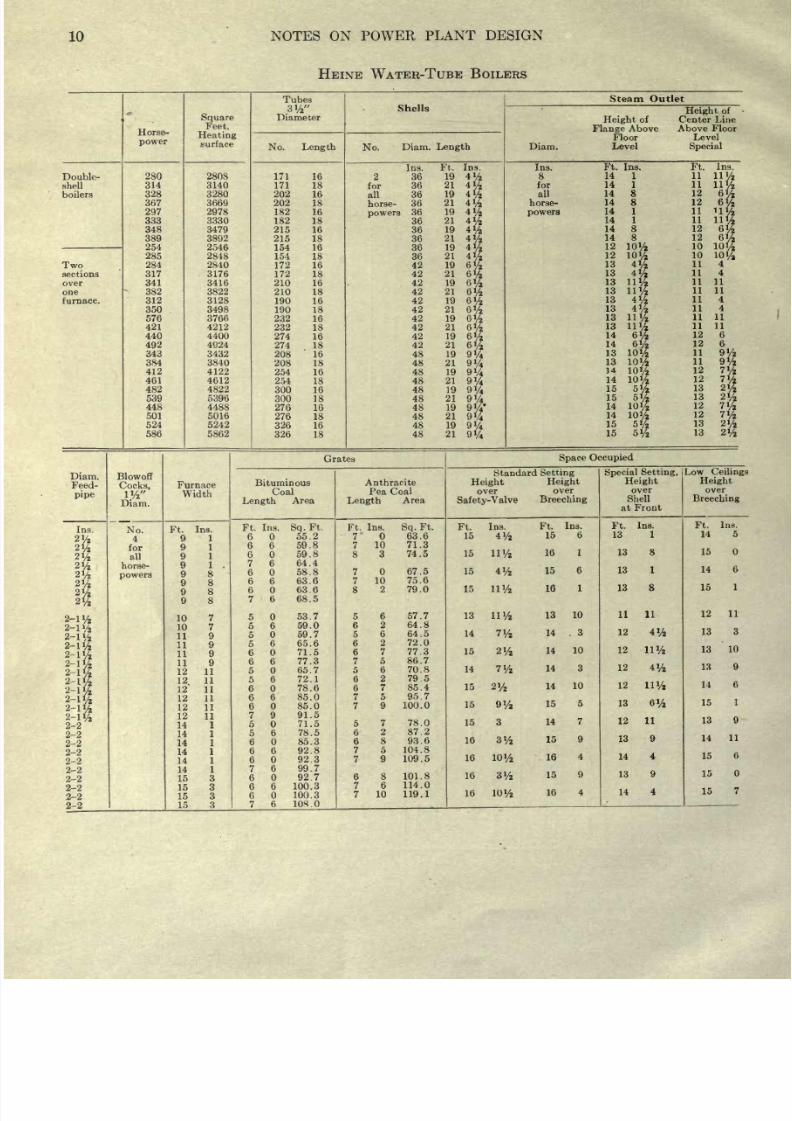
HEINE
WATER
TUBE
BOILER
This
boiler
requires
a
space
at
the
back as
it
is
cleaned
from
the ends.
Any
number
of
boilers
of
this
type
can
be set side
by
side.
The
space
in front of the boiler should
be
sufficient
to allow of
the
renewal
of a tube.
The
length
of
setting
from
fire front
to
rear
of
brickwork is
always
1
foot
4
inches
longer
than
the
length
of the
tubes,
for
instance,
the
setting
of a
90
horse-power
boiler is 17
feet
4
inches
long
and a
101
horse-power
boiler
is 19 feet
4
inches
long.
The
shell
with manhead extends
about
15
inches
beyond
rear
of
setting,
so that
if
possible
a
4-foot
space
should
be
allowed behind
the
setting
for access to
same.
In
special
cases
the
manhole
is
placed
in the
front
head,
or
an
opening may
be made in the
building
wall
opposite
manhole,
in
which
case
2 feet
behind
setting
will be
sufficient,
The
width of
setting
may
be
determined
by
adding
the thickness of brick
walls
to the
width
of
furnace.
Thus,
three
101
horse-power
boilers
in
a
battery,
with
19 inches side and 28 inches divi-
sion
walls,
will
be
19['
+
53
+
28
+
53
+
28
+
53
+
19
=
21' 1 .
Existing
walls
may
be
utilized
where
space
is
limited,
and the
outside
walls
here
reduced
to
a
furnace
lining
9
or
10
inches
thick.
The
grate-surface
given
for
bituminous coal is
such that the
rating
may
be
easily
developed
with
a
}/2-inch draught
at the smoke outlet. The
grate
area
given
for anthracite
pea
coal is that
necessary
in
order
to
develop
the
rating
of the boiler
with
V^-inch
draught
at
the
smoke
outlet.
For convenience of
handling
it
is
advisable
to
limit
the
grate length
for anthracite coal
to
7 feet
6
inches. Where this
does
not
give
area
enough
for the desired
maximum
capacity
it
is
necessary
to increase the
draught.
Standard
grate
lengths
are
6
feet
6
inches,
7 feet
and
7
feet
6 inches.
Safety-valves
are
provided
as
required
to
meet
local
inspection
laws.
8/20/2019 notes on powerplant.pdf
http://slidepdf.com/reader/full/notes-on-powerplantpdf 15/202
NOTES
ON
POWER
PLANT
DESIGN
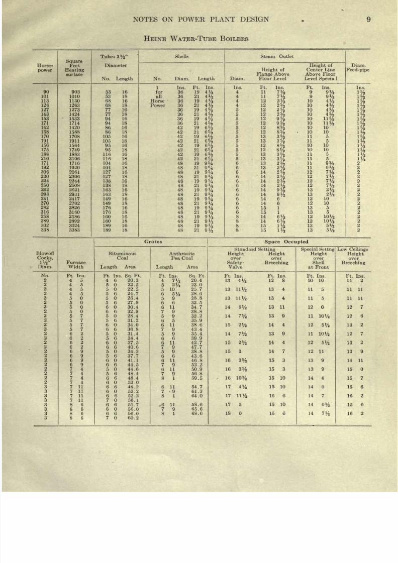
HEINE
WATER-TUBE
BOILERS
8/20/2019 notes on powerplant.pdf
http://slidepdf.com/reader/full/notes-on-powerplantpdf 16/202
10
NOTES ON
POWER
PLANT
DESIGN
HEINE WATER-TUBE
BOILERS
8/20/2019 notes on powerplant.pdf
http://slidepdf.com/reader/full/notes-on-powerplantpdf 17/202
NOTES
ON
POWER
PLANT
DESIGN
11
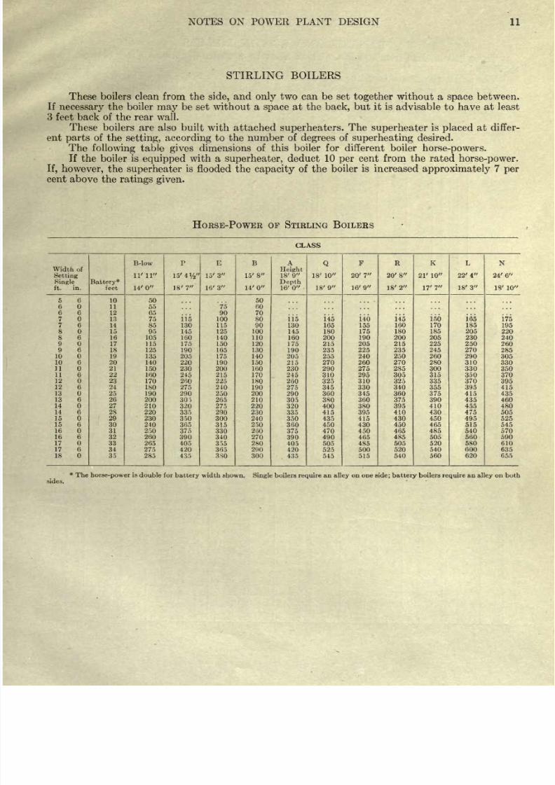
STIRLING
BOILERS
These boilers
clean from
the
side,
and
only
two
can
be
set
together
without
a
space
between.
If
necessary
the
boiler
may
be
set
without a
space
at
the
back,
but
it is
advisable to
have
at
least
3
feet
back
of
the rear wall.
These
boilers
are
also built
with
attached
superheaters.
The
superheater
is
placed
at
differ-
ent
parts
of
the
setting,
according
to
the
number
of
degrees
of
superheating
desired.
The
following
table
gives
dimensions
of
this
boiler
for
different
boiler
horse-powers.
If
the
boiler
is
equipped
with
a
superheater,
deduct
10
per
cent
from
the
rated
horse-power.
If,
however,
the
superheater
is
flooded the
capacity
of the
boiler is increased
approximately
7
per
cent
above
the
ratings
given.
HORSE-POWER OF STIRLING
BOILERS
CLASS
Width of
Setting
Single
ft.
in.
8/20/2019 notes on powerplant.pdf
http://slidepdf.com/reader/full/notes-on-powerplantpdf 18/202
12 NOTES
ON
POWER
PLANT
DESIGN
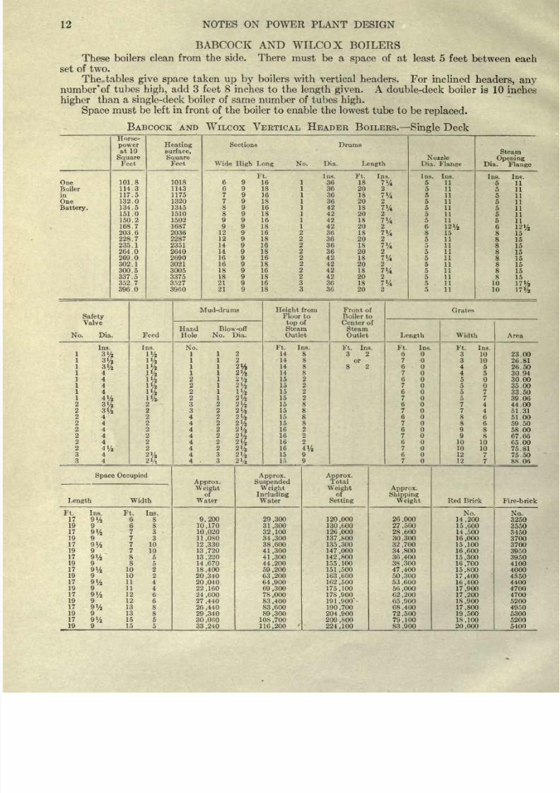
BABCOCK AND
WILCOX
BOILERS
These
boilers
clean
from
the side.
There
must
be a
space
of
at
least
5
feet between
each
set
of
two.
The
tables
give
space
taken
up
by
boilers
with
vertical
headers.
For
inclined
headers, any
number'
of
tubes
high,
add 3
feet
8
inches to
the
length
given.
A
double-deck boiler
is
10
inches
higher
than
a
single-deck
boiler
of
same number of
tubes
high.
Space
must be
left
in
front
of
the
boiler to
enable
the
lowest
tube
to
be
replaced.
BABCOCK AND
WILCOX
VERTICAL
HEADER
BOILERS.
Single
Deck
8/20/2019 notes on powerplant.pdf
http://slidepdf.com/reader/full/notes-on-powerplantpdf 19/202
NOTES ON
POWER
PLANT
DESIGN
13
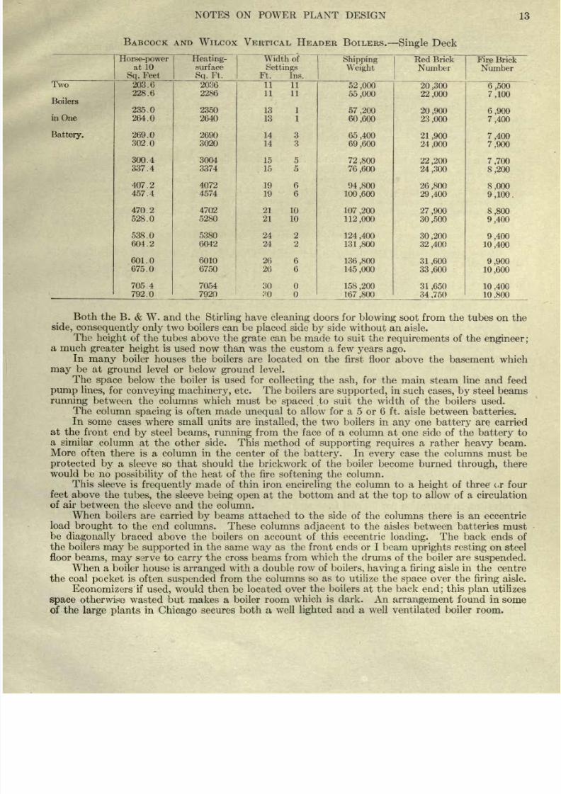
BABCOCK AND
WILCOX
VERTICAL
HEADER
BOILERS.
Single
Deck
8/20/2019 notes on powerplant.pdf
http://slidepdf.com/reader/full/notes-on-powerplantpdf 20/202
8/20/2019 notes on powerplant.pdf
http://slidepdf.com/reader/full/notes-on-powerplantpdf 21/202
NOTES
ON
POWER
PLANT
DESIGN
15
to
flow
through
the suction
pipe
of
the
oil
pump
supplying
the burners with
oil
under
30
to 50
Ibs.
pressure.
The exhaust
of the
oil
pump
is
frequently
used to
still
further heat
the
oil
before
it
enters
the
burner.
The
temperature
of
the
oil
should
not
be
high enough
to
cause
the
gas
to
volatilize
as this
would
cause
the
flame
at
the
burner to be
extinguished
and
might
result
in
a
flooding
of
the furnace
and
an
explosion.
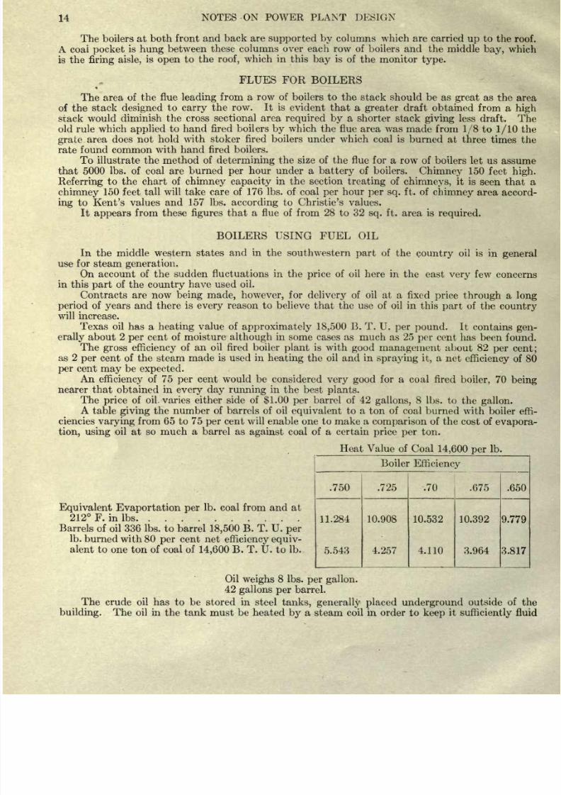
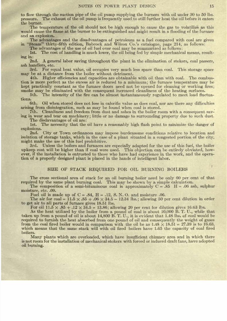
The
advantages
and the
disadvantages
of
petroleum
as a fuel
compared
with
coal are
given
in
Steam
thirty-fifth edition,
Babcock
and
Wilcox Co.'s
catalogue,
page
214,
as follows:
The
advantages
of
the use
of
oil
fuel
over
coal
may
be
summarized as
follows
:
1st.
The
cost
of
handling
is
much
lower,
the
oil
being
fed
by
simple
mechanical means,
result-
ing
in:
2nd. A
general
labor
saving throughout
the
plant
in
the
elimination of
stokers,
coal
passers,
ash
handlers,
etc.
3rd.
For
equal
heat
value,
oil
occupies
very
much
less
space
than
coal.
This
storage space
may
be
at
a
distance
from the
boiler
without
detriment.
4th.
Higher
efficiencies
and
capacities
are
obtainable
with
oil
than
with
coal.
The combus-
tion
is more
perfect
as
the excess air
is
reduced
to
a
minimum;
the furnace
temperature
may
be
kept
practically
constant as
the
furnace
doors
need
not
be
opened
for
cleaning
or
working
fires;
smoke
may
be
eliminated
with the
consequent
increased
cleanliness
of
the
heating
surfaces.
5th. The
intensity
of
the
fire can be
almost
instantaneously regulated
to meet
load fluctua-
tions.
6th.
Oil
when
stored
does not lose
in
calorific value
as does
coal,
nor
are
there
any
difficulties
arising
from
disintegration,
such as
may
be
found
when
coal is
stored.
7th. Cleanliness
and
freedom
from
dust
and
ashes
in
the
boiler room with
a
consequent
sav-
ing
in
wear
and tear
on
machinery;
little
or no
damage
to
surrounding property
due to
such
dust.
The
disdavantages
of
oil
are
:
1st.
The
necessity
that the
oil
have a
reasonably
high
flash
point
to
minimize
the
danger
of
explosions.
2nd.
City
or
Town
ordinances
may impose
burdensome
conditions
relative to location
and
isolation
of
storage tanks,
which
in
the
case
of a
plant
situated
in
a
congested
portion
of
the
city,
might
make
the use
of
this
fuel
prohibitive.
3rd. Unless
the
boilers
and
furnaces
are
especially
adapted
for
the use
of this
fuel,
the boiler
upkeep
cost
will
be
higher
than
if
coal
were
used. This
objection
can
be
entirely
obviated,
how-
ever,
if the
installation
is
entrusted
to those who
have had
experience
in the
work,
and
the
opera-
tion
of
a
properly designed
plant
is
placed
in
the
hands
of intelligent
labor.
SIZE OF
STACK
REQUIRED
FOR
OIL
BURNING
BOILERS
The
cross sectional area
of
stack
for
an
oil
burning
boiler
need
be
only
60
per
cent of
that
required
by
the
same
plant
burning
coal. This
may
be
shown
by
a
simple
calculation.
The
composition
of a
semi-bituminous
coal
is
approximately
C
=
.85
H
=
.06
ash,
sulphur
moisture,
etc. .09.
Fuel
oil
is
made
up
of
C
=
.84,
H
=
.12,
S.
N.
O. and moisture
.06.
The air for
coal
=
11.5
X
.85
+
.06
x
34.5
=
12.34
Ibs.; allowing
50
per
cent
dilution
in
order
to
get
air
to
all
parts
of
furnace
gives
18.51 Ibs.
For
oil
11.5
x
.85
+
.12
x
34.5
=
13.86;
allowing
20
per
cent
for
dilution
gives
16.63
Ibs.
As
the
heat
utilized
by
the
boiler
from
a
pound
of coal
is
about
10,000
B. T.
U.,
while that
taken
up
from
a
pound
of oil
is
about
14,800
B. T.
U.,
it
is
evident
that
1.48
Ibs. of
coal
would
be
required
to
furnish
the
heat
absorbed
from
one
pound
of oil and
consequently
the
weight
of
gases
from
the coal fired
boiler
would
in
comparison
with
the
oil be
as
1.48
x
18.51
=
27.39
is to
16.63,
which
means
that
the
same
stack
will with
oil
fired boilers
have
1.65 the
capacity
of coal
fired
boilers.
Many
plants
which
are
overloaded,
which have insufficient
chimney
area
and in
which there
is not
room
for
the
installation
of
mechanical stokers
with forced or
induced draft
fans,
have
adopted
oil
burning.
8/20/2019 notes on powerplant.pdf
http://slidepdf.com/reader/full/notes-on-powerplantpdf 22/202
16
NOTES ON
POWER
PLANT
DESIGN
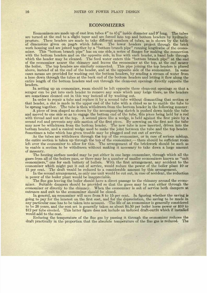
ECONOMIZERS
Economizers
are
made
up
of cast
iron
tubes
4
to
4}/
inside
diameter
and
9'
long.
The tubes
are
turned at
the
end
to
a
slight taper
and
are forced
into
top
and
bottom headers
by hydraulic
pressure.
These
headers are made to
take
different
numbers
of
tubes,
as
is
shown
by
the
table
of
dimensions
given
on
page's
which
follow.
The lower
headers
project through
the brick
work
housing
and
are
joined
together
by
a
bottom
branch
pipe
running
lengthwise
of
the
econo-
mizer. This
bottom
branch
pipe
has on
one
side,
a
series
of
flanges
for
making
the
connection
with
the
bottom
headers and on the
opposite
side,
in line
with
each
header,
a hand
hole
through
which
the header
may
be cleaned.
The
feed water
enters
this
bottom branch
pipe
at
the end
of
the
economizer
nearer
the
chimney
and leaves the economizer
at
the
top,
at
the
end
nearer
the
boiler.
The
top
headers are
similarly
connected.
This
pipe
joining
the
top
headers is
placed
above,
instead
of
at
the
end
of
the
header,
and at the
opposite
side of the
economizer.
In
some
cases
means are
provided
for
washing
out
the
bottom
headers, by
sending
a
stream
of
water
from
a
hose down
through
the tubes
at the
back
end
of the
bottom headers and
letting
it
flow
along
the
entire
length
of
the
bottom
headers
and
out
through
the
clean-out
openings
directly opposite
the
headers.
In
setting up
an
economizer,
room
should be
left
opposite
these
clean-out
openings
so
that
a
scraper
can
be
put
into each
header to
remove
any
scale which
may
lodge there,
as the
headers
are
sometimes
cleaned
out
in this
way
instead
of
by
washing
out.
In
order to
repair
a
tube
and
replace
it
by
a second tube without
dismantling
that
section or
that
header,
a
slot is
made
in
the
upper
end
of
the
tube with a chisel so as
to enable the
tube
to
be
sprung
together.
The
tube
is
then withdrawn from
the bottom
header
in the
following
manner
:
A
piece
of iron
shaped
as
shown
by
the
accompanying
sketch
is
pushed
down inside the tube
and moved to one
side
so
as to
engage
the
bottom
end
of
the
tube,
this
piece
being
held
by
a rod
with
thread and nut
at
the
top.
A
second
piece
like
a
wedge,
is held
against
the
first
piece by
a
second
rod
and
prevents
any
side
motion
of
the
first
piece.
By
screwing
on
the first nut the
tube
may
now
be
withdrawn
from the bottom
header.
The new tube is now
inserted,
driven
into
the
bottom
header,
and a conical
wedge
used
to
make the
joint
between the
tube
and the
top
header.
Sometimes a
tube
which
has
given
trouble
may
be
plugged
and
cut out
of
service.
As
the
tubes are
withdrawn
through
the
top
of the
economizer,
or
in case
of
serious
mishap,
the
entire
section
is taken
up
through
the
top
of
the
economizer,
there
should
be
sufficient room
left
over
the
economizer
to
allow for
this. The
arrangement
of the
brickwork should
be
such as
to enable a section to be
withdrawn
without
making
it
necessary
to take down
a
large
amount
of
masonry.
The
heating
surface needed
may
be
put
either
in
one
large
economizer,
through
which
all
the
gases
from all
of
the
boilers
pass,
or there
may
be a
number of
smaller
economizers
known
as unit
economizers,
one
for each
battery
of
boilers.
With the
first
arrangement,
any
accident
to
the
economizer
which
might put
it
out
of
service,
would reduce
the
power
of the
boiler
plant
10
or
15
per
cent.
The
draft would be reduced
to
a
considerable
amount
by
this
arrangement.
In
the
second
arrangement,
as
only
one
unit
would
be
cut
out,
in
case of
accident,
the
reduction
in
power
of
the
boiler
plant
would
be
inappreciable.
The
flue
gas
leaving
the
boiler
should
have
a
direct
passage
to
the
chimney
around
the
econo-
mizer. Suitable
dampers
should
be
provided
so
that
the
gases may
be sent
either
through
the
economizer
or
directly
to
the
chimney.
When
the
economizer
is out
of
service
both
dampers
at
entrance and exit
to
the
economizer
should
be
closed.
In
general,
an
economizer
will
save
from 8
to 15
per
cent. In
figuring
whether
the
saving
is
going
to
pay
for
the
interest
on
the
first
cost,
and
for
the
depreciation,
the
saving
to be
made in
any
particular
case has to be taken into account.
The
life of
an
economizer
is
generally
considered
to
be
20
years,
and
the cost
set
is
generally
taken
as about
$4.50
per
boiler
horse
power
or
$10
to
$12
per
tube
erected.
This latter
figure
does
not
include an induced
draft-outfit
which
if installed
would
add
to the
cost.
Reducing
the
temperature
of
the flue
gas
by
passing
it
through
the
economizer
reduces
the
draft
practically
in
the
proportion
that the absolute
temperature
of
the
flue
gas
is
reduced. The
8/20/2019 notes on powerplant.pdf
http://slidepdf.com/reader/full/notes-on-powerplantpdf 23/202
NOTES
ON
POWER
PLANT
DESIGN
17
draft
is still
further
reduced
by
the
friction
of
the
gas
in
passing
through
the
economizer
and in
the
many
instances
where
the
draft
is
poor,
it
would
be
unwise
to
install
an
economizer
unless
an
induced
draft
fan
were
to
be installed
also.
Usually
on the
side of
the
economizer
there is
a
space
about
12
inches
wide
left
between
the
last
tubes
and the
casing
or
brickwork,
to
allow
of
inspection.
Sometimes
there
are
two such
passages,
one
either
side
of
the
economizer.
These
passages
are closed
by
side
dampers
when
the
economizer
is
in use.
Provision should
be
made
for
removing
the soot
from the
bottom of the
economizer.
To
remove
the soot which
collects
on
the
tubes,
scrapers
are
provided,
these
scrapers
being
in
the
form
of
loose
collars which
are
alternately
raised and
lowered
by
chains
operated
from a
shaft run-
ning
along
the
top
of
the economizer.
If
the
economizer
is
only eight
tubes
wide,
one
shaft
will
serve,
but
if
the
economizer
is
ten
or
twelve tubes
wide
there should
be
two
sets of
stmfts.
In
place
of the
brickwork
walls
a
sectional
covering
of
steel bolted
together
through angle
irons
may
be
used.
This
covering
is
insulated
by
building
it
up
of two
steel
plates
with
2
of
magnesia
or
asbes-
tos
as
an
insulating
material
between.
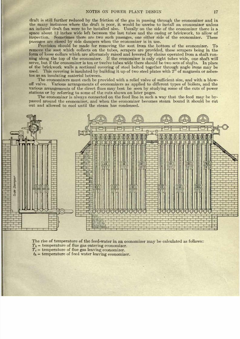
The
economizers
must each be
provided
with
a
relief
valve
of
sufficient
size,
and
with
a
blow-
off
valve.
Various
arrangements
of
economizers
as
applied
to
different
types
of
boilers,
and
the
various
arrangements
of
the
direct flues
may
best
be seen
by studying
some
of
the
cuts
of
power
stations
or
by
referring
to
some of the
cuts shown
on
later
pages.
The
economizer is
always
connected
on
the
feed
line
in
such
a
way
that the feed
may
be
by-
passed
around
the
economizer,
and when
the
economizer
becomes steam
bound
it
should
be
cut
out
and
allowed
to
cool
until
the steam
has
condensed.
The
rise of
temperature
of
the
feed-water
in an
economizer
may
be calculated
as
follows
:
Th
=
temperature
of
flue
gas
entering
economizer.
T
c
=
temperature
of
flue
gas
leaving
economizer.
th
=
temperature
of feed
water
leaving
economizer.
8/20/2019 notes on powerplant.pdf
http://slidepdf.com/reader/full/notes-on-powerplantpdf 24/202
18
NOTES ON POWER
PLANT
DESIGN
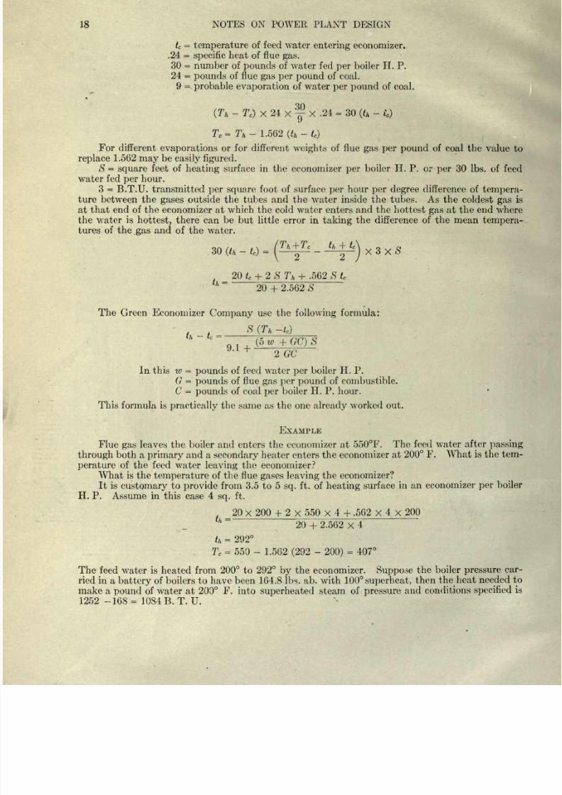
t
c
=
temperature
of feed
water
entering
economizer.
.24
=
specific
heat
of
flue
gas.
30
=
number of
pounds
of water
fed
per
boiler
H.
P.
24
=
pounds
of flue
gas
per
pound
of
coal.
9
=
probable
evaporation
of
water
per
pound
of
coal.
QA
(T
k
-
T
e
)
X
24
X
y
X
.24
=
30
(t
h
-
t
c
)
T
c
=T
h
-
1.562
(t
k
-
t
c
)
For
different
evaporations
or
for
different
weights
of
flue
gas per pound
of
coal
the
value
to
replace
1.562
may
be
easily figured.
S
=
square
feet of
heating
surface in
the
economizer
per
boiler
H. P.
or
per
30
Ibs. of feed
water fed
per
hour.
3
=
B.T.U.
transmitted
per square
foot
of surface
per
hour
per
degree
difference
of
tempera-
ture
between the
gases
outside
the tubes
and
the
water
inside
the tubes.
As
the
coldest
gas
is
at
that
end
of
the
economizer
at
which the
cold
water
enters
and
the
hottest
gas
at
the end
where
the
water
is
hottest,
there
can
be
but
little
error
in
taking
the difference of the mean
tempera-
tures
of
the
.gas
and
of
the
water.
/. . \
1
*
n~r
*
c
th
-\~
t
c
\
o
e
(lh
-
t
c
)
=
I
^
2~
)
_ 20t
c
+
2
S
T
h
+
.562
S
t
c
20
+
2.562 S
The
Green Economizer
Company
use the
following
formula:
S
(T
h
-t
c
)
th
-
tc
=
(5
w
+
GC)
S
2 GC
In
this
w
=
pounds
of feed water
per
boiler
H. P.
G
=
pounds
of flue
gas
per pound
of combustible.
C
=
pounds
of coal
per
boiler
H.
P.
hour.
This
formula is
practically
the same as
the one
already
worked out.
EXAMPLE
Flue
gas
leaves
the
boiler
and
enters
the economizer at
550F.
The
feed
water
after
passing
through
both
a
primary
and
a
secondary
heater
enters the economizer
at
200
F. What
is
the tem-
perature
of the feed water
leaving
the
economizer?
What
is
the
temperature
of the flue
gases leaving
the
economizer?
It is
customary
to
provide
from 3.5
to 5
sq.
ft.
of
heating
surface
in
an
economizer
per
boiler
H.
P.
Assume
in this case
4
sq.
ft.
_20
x
200
+
2
x
550
x
4
+
.562
x
4
x
200
20
+
2.562
x
4
t
h
=
292
T
c
=
550
-
1.562 (292
-
200)
=
407
The
feed
water is heated from
200
to
292
by
the economizer.
Suppose
the
boiler
pressure
car-
ried
in
a
battery
of
boilers to
have been
164.8 Ibs.
ab.
with
100
superheat,
then
the
heat
needed
to
make a
pound
of
water
at
200
F.
into
superheated
steam
of
pressure
and conditions
specified
is
1252
-168= 1084
B.T.U.
8/20/2019 notes on powerplant.pdf
http://slidepdf.com/reader/full/notes-on-powerplantpdf 25/202
NOTES
ON
POWER PLANT
DESIGN
19
The economizer
saved 92
B. T. U.
per
Ib.
of
water or
92
1084
=
.0849
say
8%
per
cent.
On a
coal
consumption
of
592
tons
per
week
with coal
at
$4.20
per
ton a
saving
of
8^
per
cent
amounts
in
the
course
of a
year
to
.085
X
592
x
52
x $4.20
=
$10,989
The economizer
consisting
of
672 tubes
cost
at
$12.00
a
tube,
$8,064;
the
piping
etc.
brought
the cost
up
to
$10,000.
There
should
be charged
against
the
economizer
which
may
be
assumed
to
be
worn
out
in
20
years,
a certain
percentage
for
depreciation
(see
later
pages)
which
we will
take
as
3.02
per cent,
interest
5
per
cent,
taxes
1.5
per cent,
insurance 0.5
per
cent
and
repairs
2.5
per
cent
making
a
total
of
12.52
per
cent.
.1252
x
$10,000
=
$1,252
The
saving
apparently
amounts to
10,989
-
1,252
=
$9,737
per year.
If
an induced draft had to be maintained
there
should
be
charged against
the economizer the
cost of
running
the
fan and the
interest,
depreciation,
etc.
on the cost of the outfit.
This would make the
saving
less. In
spite
of
the fact that
figures
show a decided
saving
made
by
the use of
an
economizer
many engineers
will not
recommend
their
installation.
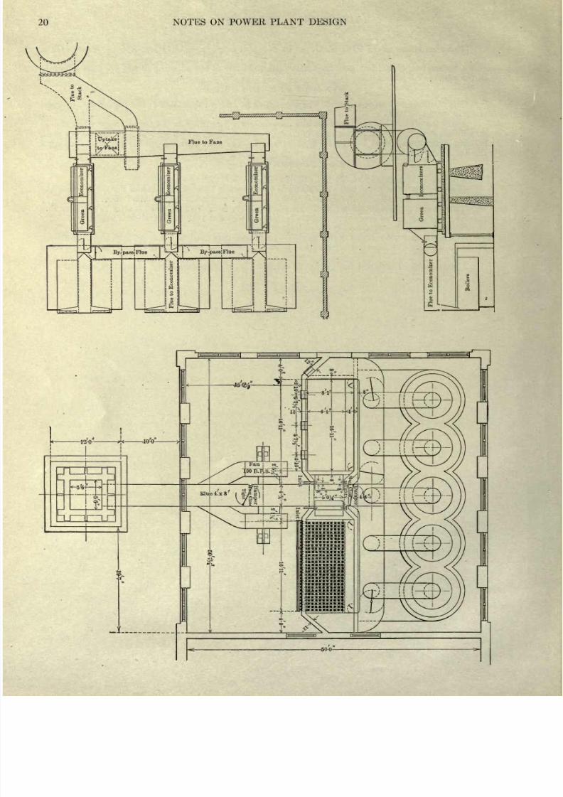
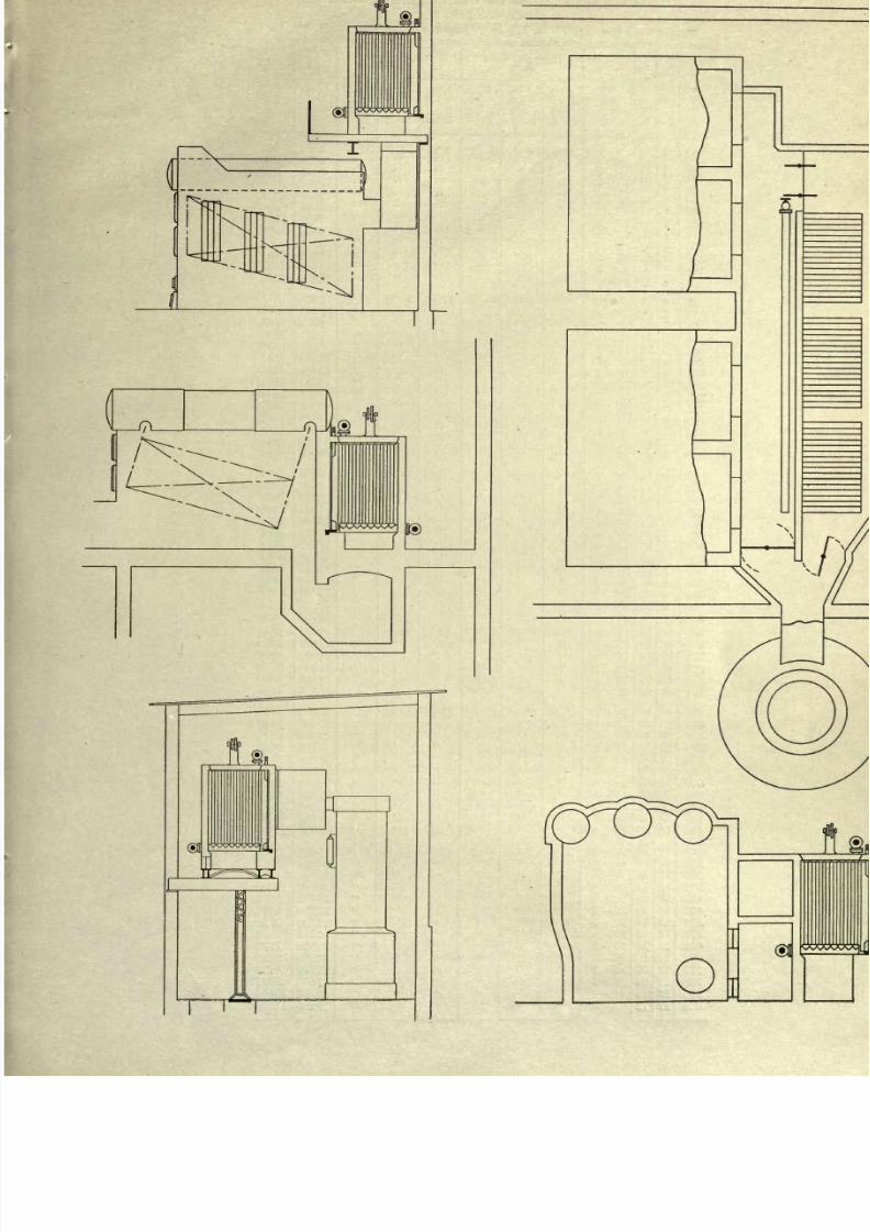
Some
arrangements
of economizers follow:
The
resistance
offered
to
the flue
gases
by
an
economizer
amounts
to
from .25 to
30
of
water.
In
many
instances
on
account of
this
loss
of
draft,
it becomes
necessary
to
install an
induced
draft
fan.
Illustrations of
induced
fan
outfits
as erected
in
two
manufacturing
plants
are
shown.
8/20/2019 notes on powerplant.pdf
http://slidepdf.com/reader/full/notes-on-powerplantpdf 26/202
20
NOTES ON
POWER
PLANT DESIGN
8/20/2019 notes on powerplant.pdf
http://slidepdf.com/reader/full/notes-on-powerplantpdf 27/202
8/20/2019 notes on powerplant.pdf
http://slidepdf.com/reader/full/notes-on-powerplantpdf 28/202
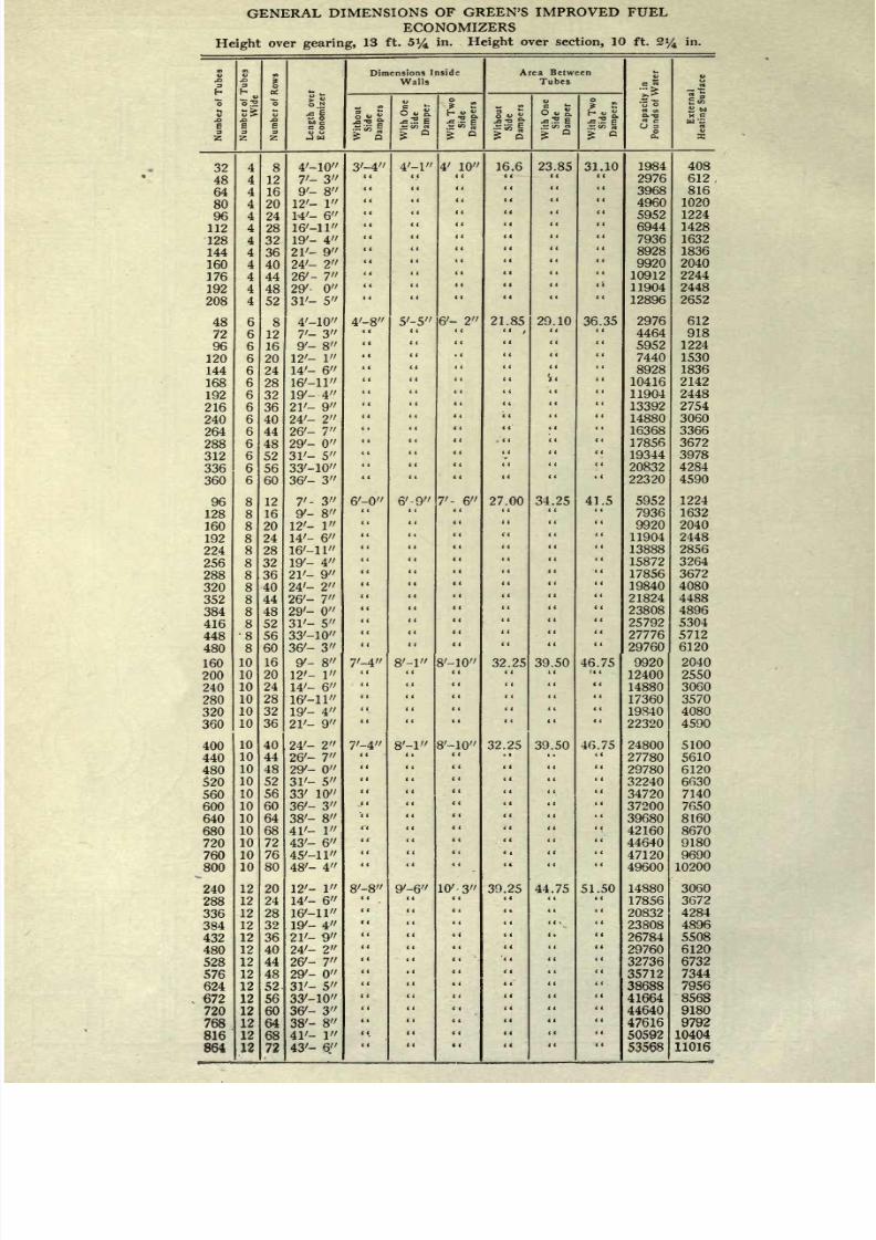
GENERAL
DIMENSIONS
OF
GREEN'S
IMPROVED
FUEL
ECONOMIZERS
Height
over
gearing,
13
ft.
5%
in.
Height
over
section,
10 ft.
2%
in.
Numbej
of
Tubes
8/20/2019 notes on powerplant.pdf
http://slidepdf.com/reader/full/notes-on-powerplantpdf 29/202
O)
Qi
O)
N
O
Z
O
u
Q
etc
<
Q
z.
<
C/)
GENERAL
D
8/20/2019 notes on powerplant.pdf
http://slidepdf.com/reader/full/notes-on-powerplantpdf 30/202
24
NOTES
ON POWER
PLANT
DESIGN
MECHANICAL
STOKERS
There
is no
question
about the
desirability
of
mechanical
stokers
in
a
plant
of 1500 H.
P.
While there
may
not
be
any
saving
in
the
cost of
labor on
a
plant
of
1500 H.
P.
the
protec-
tion
against
labor
troubles
which
a
stoker
affords warrants its
use
on
a
plant
of
this size.
On
plants
of
larger
size
the saving
in labor,
together
with
the
increased
capacity
to
be
obtained
from
the
boilers,
the freedom from
smoke
troubles,
the
insurance
against
labor
troubles and
the
ability
to
push
a
boiler from
a
banked condition to
150
per
cent
rating
in
ten
minutes
make stokers
absolutely
necessary.
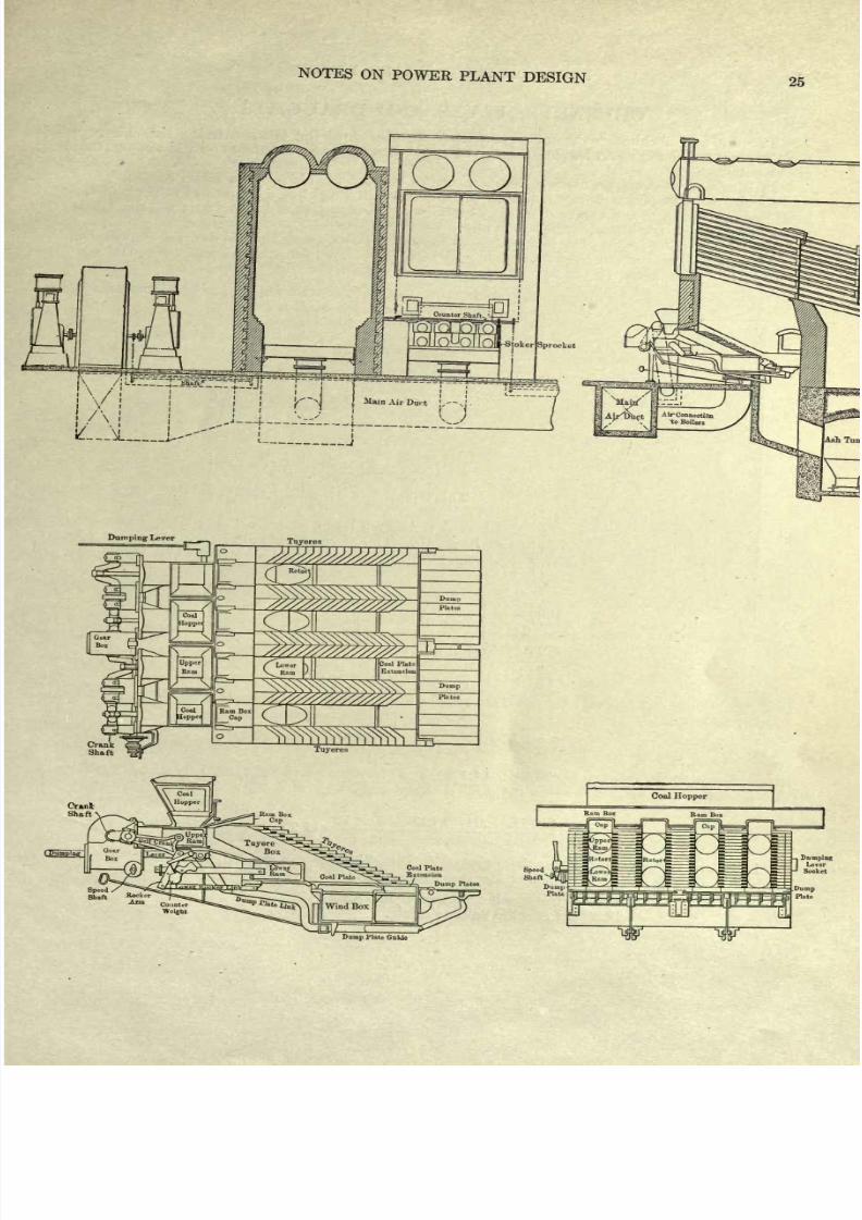
The
stokers
may
be divided into
classes:
(1)
The
Taylor
and
The
Riley
underfed
stokers,
both
similar
to the cut
following.
(2)
The
Murphy
and
the
Roney,
inclined
grates.
(3)
The
chain
grate,
like
Green,
Keystone,
and
the
Babcock &
Wilcox.
(4)
The
American;
The
Jones;
both
underfed stokers
but
differing
from
the
Riley
and
the
Taylor.
There
are others not
mentioned,
the ones
named
being
those most
commonly
found.
The
Taylor
and
the
Riley
are both
capable
of
quick forcing
and
can
be crowded
harder than
the
Murphy
or
the
Roney.
All
four
of
these
are best suited
for
a
good
grade
of soft
coal.
The
chain
grate
works
best
on
a
poorer
grade
of
coal.
The American and
The
Jones are
better suited
for
small units
than
for
large
units.
Stokers
cost
from
$6
to
$10
per
rated
H.
P. of the
boiler.
The
higher figure
includes
the cost
of
the fan
and
engine
required by
certain
types
of
stoker.
See Steam
Boilers,
Peabody
and
Miller
for more detailed
discussion
of
stokers.
The life
of
a stoker
is
from
6
to
8
years,
consequently
a
high
rate
for
depreciation
must
be
charged
against
it.
8/20/2019 notes on powerplant.pdf
http://slidepdf.com/reader/full/notes-on-powerplantpdf 31/202
NOTES
ON
POWER
PLANT
DESIGN
25
Dumping
Lever
Tuyeres
Weight
Dump
Plato
OuUe
8/20/2019 notes on powerplant.pdf
http://slidepdf.com/reader/full/notes-on-powerplantpdf 32/202
26
NOTES
ON POWER
PLANT
DESIGN
CHIMNEYS,
FLUES
AND
DRAUGHTS
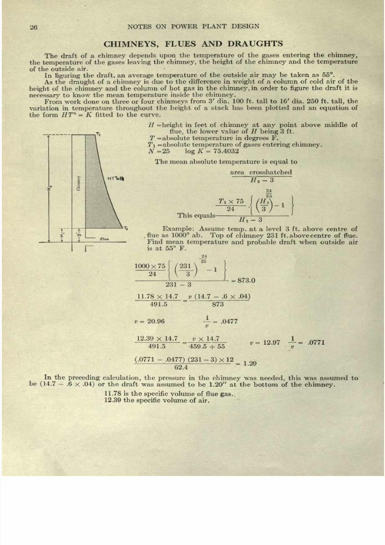
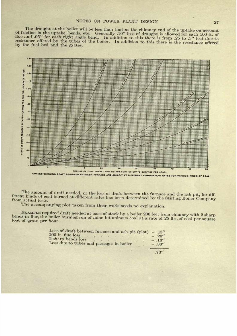
The draft
of
a
chimney depends
upon
the
temperature
of the
gases
entering
the
chimney,
the
temperature
of
the
gases
leaving
the
chimney,
the
height
of
the
chimney
and the
temperature
of
the
outside
air.
In
figuring
the
draft,
an
average
temperature
of the outside air
may
be taken
as 55.
As
the
draught
of
a
chimney
is
due
to
the
difference in
weight
of
a
column
of
cold
air
of
the
height
of the
chimney
and the column
of
hot
gas
in
the
chimney,
in order
to
figure
the draft it
is
necessary
to
know
the
mean
temperature
inside the
chimney.
From
work
done
on
three
or
four
chinmeys
from 3' dia.
100
ft. tall to 16' dia. 250 ft.
tall,
the
variation in
temperature
throughout
the
height
of
a stack
has been
plotted
and an
equation
of
the
form
HT
n
=
K
fitted
to
the
curve.
H
=
height
in
feet of
chimney
at
any point
above middle
of
flue,
the
lower value of H
being
3 ft.
T
=
absolute
temperature
in
degrees
F.
T\
=
absolute
temperature
of
gases
entering chimney.
JV=25
log
K=
75.4032
HTt.il
The
mean
absolute
temperature
is
equal
to
area
crosshatched
#2-3
This
equals
#2-3
Example:
Assume
temp,
at
a
level
3
ft.
above centre of
flue as
1000 ab.
Top
of
chimney
231
ft.
above
centre
of flue.
Find mean
temperature
and
probable
draft when
outside
air
is at 55
F.
1000x75
/231
24
24
25
-1
231
-3
=
873.0
11.78
x
14.7 v
(14.7
-
.6
x
.04)
491.5
873
v
=
20.96
-
=
.0477
v
12.39
x
14.7
491.5
_0X_14_.7_
459.5
+
55
v
=
12.97
=
.0771
v
(.0771
-
.0477) (231
-
3)
x
12
62.4
=
1.29
In the
preceding
calculation,
the
pressure
in the
chimney
was
needed,
this
was
assumed
to
be
(14.7
-
.6
x
.04)
or the
draft
was assumed
to
be
1.20
at
the
bottom of the
chimney.
11.78
is the
specific
volume
of
flue
gas.,
12.39
the
specific
volume
of air.
8/20/2019 notes on powerplant.pdf
http://slidepdf.com/reader/full/notes-on-powerplantpdf 33/202
8/20/2019 notes on powerplant.pdf
http://slidepdf.com/reader/full/notes-on-powerplantpdf 34/202
28
NOTES
ON
POWER
PLANT
DESIGN
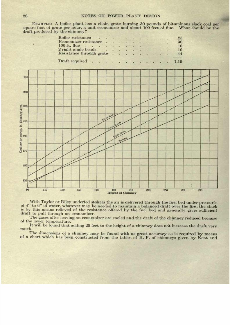
EXAMPLE:
A boiler
plant
has a chain
grate
burning
30
pounds
of
bituminous
slack
coal
per
square
foot of
grate
per
hour,
a
unit
economizer
and
about
100
feet
of
flue.
What
should be
the
draft
produced
by
the
chimney?
Boiler
resistance
Economizer
resistance
100 ft.
flue
...
2 right
angle
bends
.25
.30
.10
.10
Resistance
through
grate
44
Draft
required
1.19
270
850
230
S-190
b
a
I
170
150
130
90
110
130
150
170
190
210
Height
of
Chimney
230
250
270
^^lor
or
Riley
underfed
stokers
the air
is
delivered
through
the
fuel
bed
under
pressures
of
4
to
6
of
water,
whatever
may
be
needed to
maintain
a
balanced
draft
over the
fire;
the
stack
is
by
this
means
relieved
of
the
resistance
offered
by
the fuel bed and
generally
gives
sufficient
draft
to
pull
through
an
economizer.
The
gases
after
leaving
an
economizer
are
cooled and
the
draft
of the
chimney
reduced
because
of
the
lower
temperature.
It will
be
found that
adding
25
feet
to the
height
of
a
chimney
does
not increase
the
draft
very
much.
The
dimensions
of
a
chimney
may
be
found
with
as
great
accuracy
as is
required
by
means
of a
chart
which
has
been
constructed from
the
tables of H. P. of
chimneys given
by
Kent
and
8/20/2019 notes on powerplant.pdf
http://slidepdf.com/reader/full/notes-on-powerplantpdf 35/202
NOTES
ON
POWER
PLANT
DESIGN
29
by
Christie
(See
Steam
Boilers,
Peabody
&
Miller).
On
this
chart
the
capacities
in
Ibs.
of coal
per
hour
per
square
foot of
chimney
area
are
given
for
different
heights
of
chimney.
Knowing
the coal
to
be
burned
per
hour,
the
cross
sectional
area for
any
assumed
height
may
be
calculated.
The
ratio of
height
to
cross
section
must be
considered,
otherwise
a
poorly proportioned
chim-
ney
may
be
obtained.
For
discussion
of
the
stability
of
a
chimney
see
Steam
Boilers.
In
general
the
maximum
com-
pression
due
to both
dead load
and
wind
pressure
is
not
allowed
to
exceed
10 tons per
square
foot.
FEED
PUMPS
FOR
BOILERS
STEAM
CONSUMPTION
OF
PUMPS
The
steam
consumption
of a
duplex
pump
varies
with
the
speed
at
which
the
pump
runs
At
half
speed
or
at
one-half
rated
capacity
125
to
150
pounds
of
steam
will
in
general
be
re-
quired
per
horse
power
hour
of
water
work
done.
For
slower
speeds
the rate
may
become as
large
as
200 or
250
Ibs.
At
full
speed
and
at
rated
capacity
90
to
100
pounds
is
a
fair
value
to
use
for
the
steam consumption
per
water
horse
power
per
hour.
Turbine
driven
centrifugals
are
now
quite
generally
used
as
feed
pumps
in
the
larger
power
plants.
The
efficiency
of
a
centrifugal
pump
designed
for a
given
head
and
given
capacity
may
reach
80
Per
cent,
but
under
the
conditions
which
apply
to
centrifugals
used
as
feed
pumps
a
value
between
and
55
per
cent
should
be
used.
The
steam
consumption
for the
driving
end
may
be
obtained
trom
the
curves
already
given.
Drawings
and table
of
dimensions
of
the
Terry
steam turbine
with
centrifugal
feed
pump
are
given
on
page
39.
8/20/2019 notes on powerplant.pdf
http://slidepdf.com/reader/full/notes-on-powerplantpdf 36/202
30
NOTES
ON POWER
PLANT
DESIGN
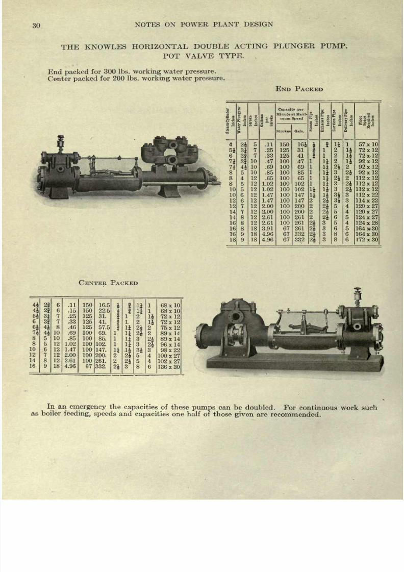
THE
KNOWLES
HORIZONTAL
DOUBLE
ACTING
PLUNGER
PUMP.
POT
VALVE
TYPE.
End
packed
for
300
Ibs.
working
water
pressure.
Center
packed
for
200 Ibs.
working
water
pressure.
END PACKED
1
8/20/2019 notes on powerplant.pdf
http://slidepdf.com/reader/full/notes-on-powerplantpdf 37/202
NOTES
ON
POWER PLANT
DESIGN
31
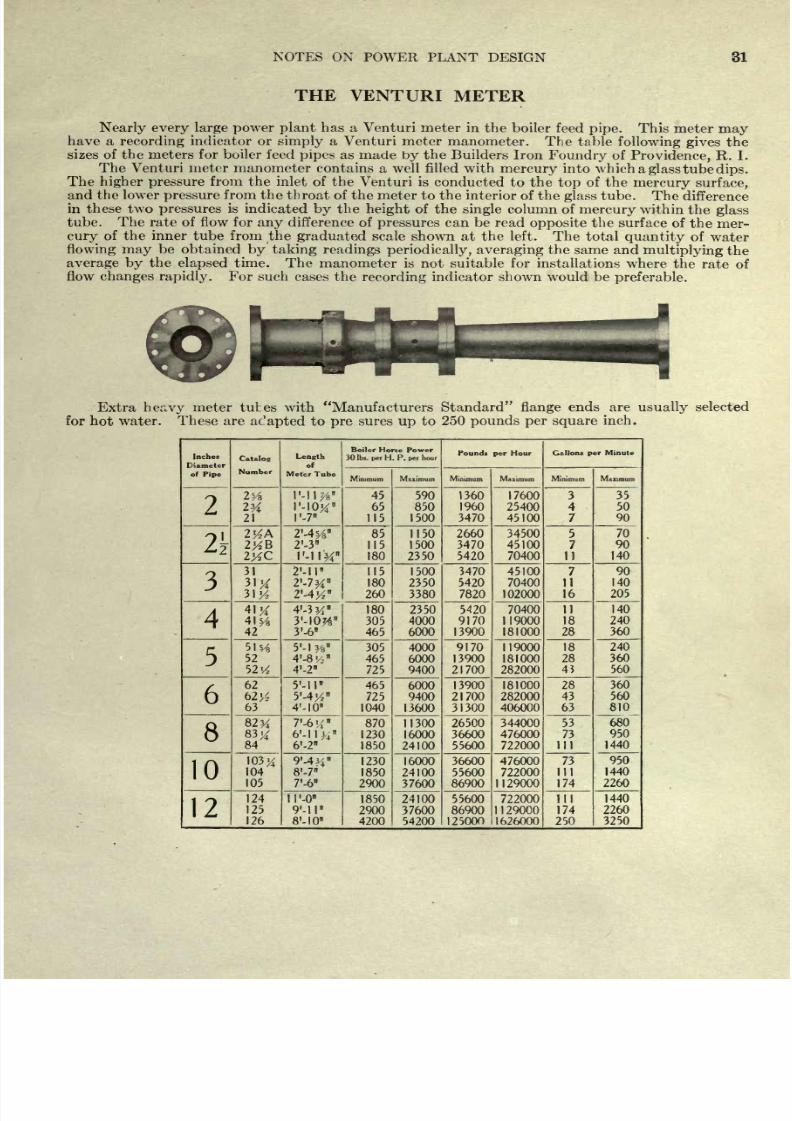
THE
VENTURI
METER
Nearly every
large
power plant
has
a
Venturi meter
in the boiler
feed
pipe.
This meter
may
have
a
recording
indicator
or
simply
a
Venturi meter
manometer.
The
table
following gives
the
sizes
of the
meters
for boiler feed
pipes
as made
by
the Builders Iron
Foundry
of
Providence,
R.
I.
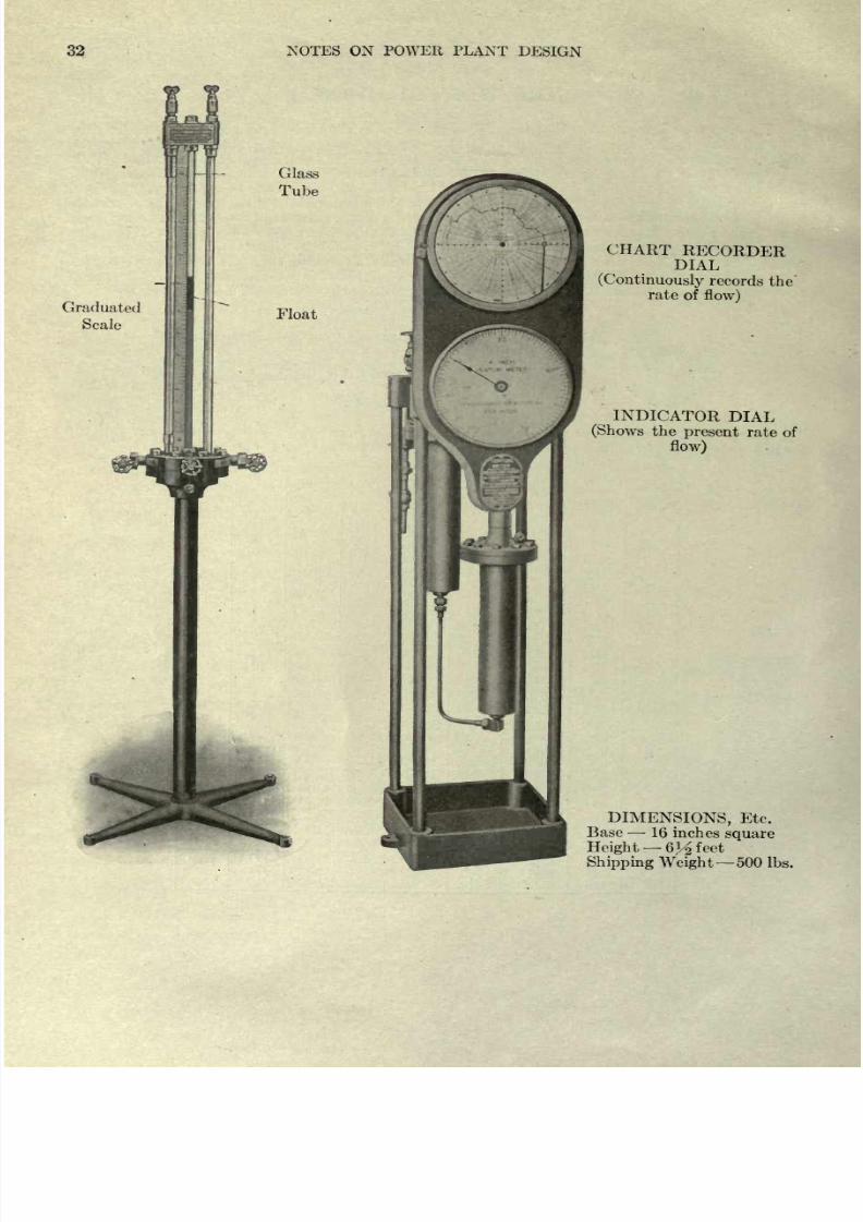
The
Venturi
meter
manometer
contains
a
well
filled
with
mercury
into
which
a
glass
tube
dips.
The
higher
pressure
from
the
inlet of
the
Venturi is
conducted
to
the
top
of
the
mercury
surface,
and the lower
pressure
from the
throat
of
the
meter
to the
interior of the
glass
tube.
The
difference
in
these
two
pressures
is
indicated
by
the
height
of
the
single
column of
mercury
within
the
glass
tube.
The
rate of flow for
any
difference
of
pressures
can
be
read
opposite
the
surface
of
the
mer-
cury
of
the
inner tube
from
the
graduated
scale
shown
at the left.
The
total
quantity
of
water
flowing
may
be
obtained
by
taking
readings
periodically,
averaging
the
same
and
multiplying
the
average
by
the
elapsed
time. The
manometer
is
not suitable for
installations
where
the
rate
of
flow
changes rapidly.
For
such
cases
the
recording
indicator shown
would be
preferable.
Extra
heavy
meter tubes
with
Manufacturers
Standard
flange
ends are
usually
selected
for hot
water. These are
ac'apted
to
pre
sures
up
to
250
pounds per
square
inch.
Inches
Diameter
of
Pipe
8/20/2019 notes on powerplant.pdf
http://slidepdf.com/reader/full/notes-on-powerplantpdf 38/202
32
NOTES
ON
POWER
PLANT
DESIGN
Graduated
Scale
*
Glass
Tube
Float
CHART
RECORDER
DIAL
(Continuously
records
the
rate
of
flow)
INDICATOR
DIAL
(Shows
the
present
rate
of
flow)
DIMENSIONS,
Etc.
Base
16
inches
square
Height
6^
feet
Shipping
Weight
500
Ibs.
8/20/2019 notes on powerplant.pdf
http://slidepdf.com/reader/full/notes-on-powerplantpdf 39/202
NOTES
ON
POWER
PLANT
DESIGN
33
CALIBRATION
TESTS
ON
METERS
IN
SERVICE
Test
No.
1.
Made
at
Worcester
Polytechnic
Institute
on
4-inch
meter
tube
No.
2319
1^
inch
throat,
equipped
with
manometer.
Water
was
pumped
through
the
meter
tube
into
a
very
large
wooden
tank
resting
on
platform
scales,
which
form
a
part
of
the
regular
laboratory equip-
Ihe
manometer
was
placed
on
the
floor
immediately
below
the
meter
tube
to
which
it
was
connected
by
flexible
pipes.
The rated
capacity
of
this
meter
is
9,170
to 119
000
pounds
per
hour.
The
results
were
as
follows:
Cumbers
Pounds of
Water
Per
Hour
Error
of
Meter
Meter
Manometer
Actual
Weight
Manometer
120,600
122,640
-
1.87%
90,000
89,820
+0.20%
59,950
59,940
+
0.02%
4
and 5
30,000
29,370
+2.10%
6and7
9,000
8,950
+0.55%
(M
Te
^;
2
\/u
r
inC
,
h
Ty
entur
J,
Meter
(
ll
^~
mch
throa
t)
at
the
plant
of
the
Woonsocket
(Mass
)
Electric
Machine
&
Power
Company.
W;
ter
pumped
by
duplex
feed
pump
to
two bar-
rels
which
were
filled
alternately,
the
weight
of
water
which
each
would
hold
having
been
deter-
mined
previously.
The
test
lasted five
hours
and
the
flow
was
continuous.
Corrected
weight
of
water
by
barrels
...
132
802
Ibs
Corrected
weight
of
water
by
Venturi
.
.
.
.
131^000
Ibs
Difference,
1.35%.
Test
No.
3
Four-inch
Venturi
Meter
(1^-inch
throat)
at
plant
of
Brown
&
Sharpe Mfg.
Company,
Providence.
Meter
Tube
was
located
on
suction
side of
single
plunger
pump
and
1
water
was
from
two
calibrated
open
heaters
(emptied
alternately)
to
Meter
Tube
to
pump.
Total
pounds
of
water
by
heaters
.
.
.
392
453
1
DS
Total
pounds
of
water
by
Venturi
Meter
.
397*104 Ibs
Difference,
1.18%.
Duration
of
test,
10
hours.
A
paper
prepared
by
Prof.
C.
M.
Allen
presented
before
the
A.
S.
M.
E.
gives
a
full
discus-
sion
ot
the
Venturi
Meter
as
applied
for
measuring
feed
water.
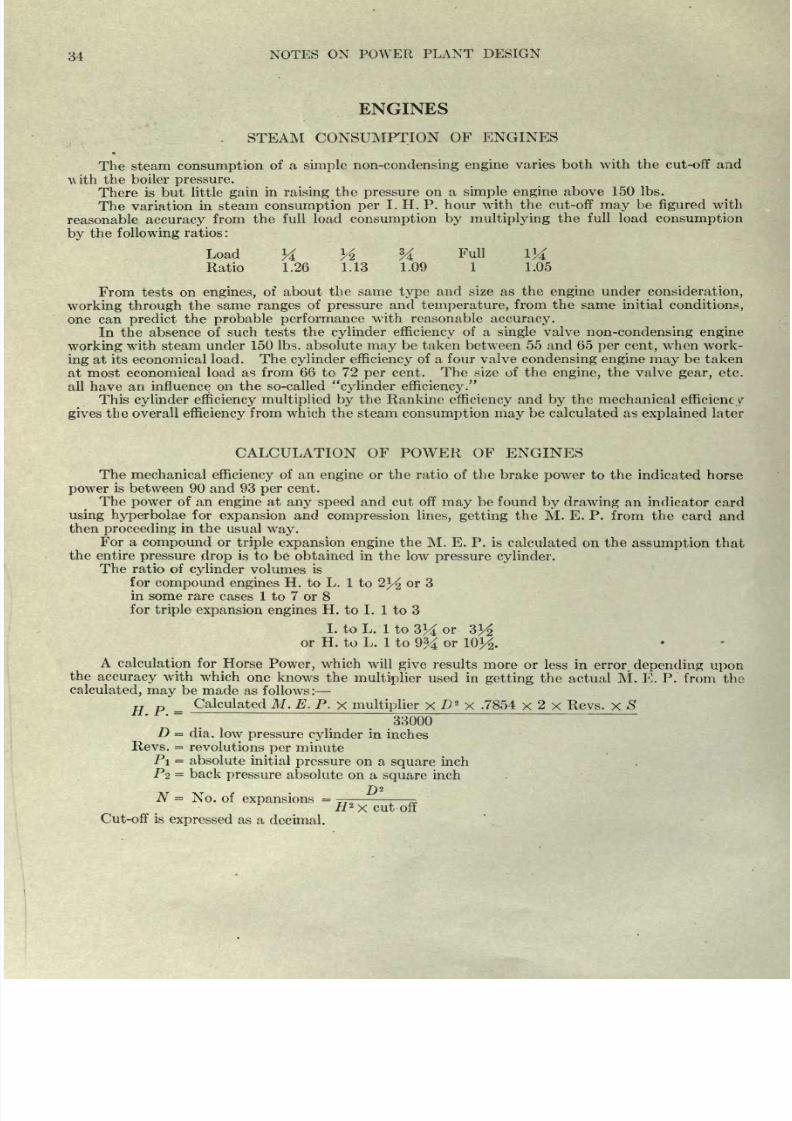
8/20/2019 notes on powerplant.pdf
http://slidepdf.com/reader/full/notes-on-powerplantpdf 40/202
34
NOTES
ON
POWER
PLANT
DESIGN
ENGINES
The
steam
consumption
of
a
simple
non-condensing
engine
varies
both
with
the
cut-off
and
N\
ith
the
boiler
pressure.
There
is
but
little
gain
in
raising
the
pressure
on a
simple
engine
above 150
Ibs.
The variation
in steam
consumption per
I. H. P.
hour with the
cut-off
may
be
figured
with
reasonable
accuracy
from
the
full load
consumption
by multiplying
the
full load
consumption
by
the
following
ratios:
Load
M
Yi
Y
Full
IK
Ratio
1.26
1.13
1.09
1
1.05
From
tests on
engines,
of about
the
same
type
and
size as the
engine
under
consideration,
working
through
the
same
ranges
of
pressure
and
temperature,
from
the
same initial
conditions,
one
can
predict
the
probable
performance
with
reasonable
accuracy.
In
the
absence
of
such tests the
cylinder
efficiency
of a
single
valve
non-condensing
engine
working
with
steam
under
150
Ibs. absolute
may
be
taken
between
55 and 65
per
cent,
when work-
ing
at
its
economical
load. The
cylinder
efficiency
of a four valve
condensing
engine
may
be
taken
at most
economical
load
as from
66
to
72
per
cent.
The
size
of the
engine,
the valve
gear,
etc.
all
have
an influence
on
the so-called
cylinder
efficiency.
This
cylinder
efficiency multiplied
by
the Rankine
efficiency
and
by
the mechanical
efficiency
gives
the overall
efficiency
from
which
the
steam
consumption may
be
calculated as
explained
later
CALCULATION
OF
POWER
OF
ENGINES
The mechanical
efficiency
of
an
engine
or the
ratio
of
the
brake
power
to
the
indicated
horse
power
is
between
90
and
93
per
cent.
The
power
of
an
engine
at
any
speed
and
cut
off
may
be found
by
drawing
an
indicator
card
using
hyperbolae
for
expansion
and
compression lines, getting
the
M.
E.
P.
from the
card
and
then
proceeding
in
the
usual
way.
For a
compound
or
triple expansion
engine
the M.
E.
P.
is
calculated
on the
assumption
that
the
entire
pressure
drop
is to
be
obtained
in
the
low
pressure
cylinder.
The ratio of
cylinder
volumes
is
for
compound
engines
H. to L. 1
to
2}/2
or 3
in
some
rare
cases
1
to
7
or
8
for
triple
expansion
engines
H.
to
I. 1
to 3
I.
to L.
1
to
3^
or
or
H.
to
L.
1
to
9%
or
A
calculation
for
Horse
Power,
which
will
give
results
more
or
less
in
error,
depending
upon
the
accuracy
with
which
one
knows
the
multiplier
used
in
getting
the
actual
M.
E.
P.
from
the
calculated,
may
be made
as
follows
:
H p
=
Calculated M.
E.
P.
x
multiplier
x
D
2
X
.7854
x
2
x
Revs,
x
S
33000
D
=
dia.
low
pressure
cylinder
in
inches
Revs.
=
revolutions
per
minute
PI
=
absolute
initial
pressure
on
a
square
inch
PZ
=
back
pressure
absolute on a
square
inch
N
=
No.
of
expansions
=
H
2
x
cut
off
Cut-off is
expressed
as a
decimal.
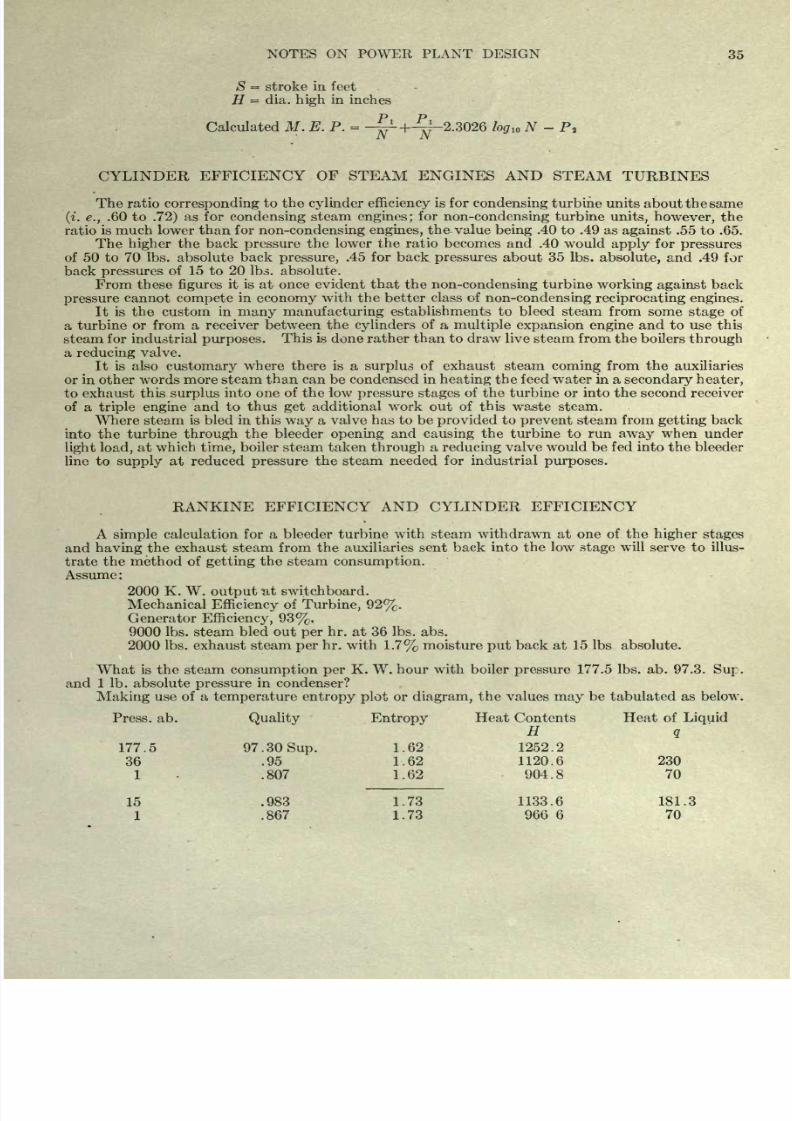
8/20/2019 notes on powerplant.pdf
http://slidepdf.com/reader/full/notes-on-powerplantpdf 41/202
NOTES
ON POWER PLANT DESIGN
35
S
=
stroke in
feet
H
=
dia.
high
in
inches
Calculated
M.
E. P.
=
--+^-2.3026
log
w
N
-
P
t
CYLINDER
EFFICIENCY
OF
STEAM
ENGINES
AND
STEAM
TURBINES
The
ratio
corresponding
to
the
cylinder
efficiency
is
for
condensing
turbine units
about the same
(i. e.,
.60 to
.72)
as
for
condensing
steam
engines;
for
non-condensing
turbine
units,
however,
the
ratio
is
much lower than
for
non-condensing
engines,
the value
being
.40
to .49
as
against
.55
to .65.
The
higher
the
back
pressure
the
lower the ratio becomes and .40
would
apply
for
pressures
of
50
to
70
Ibs. absolute
back
pressure,
.45
for back
pressures
about
35
Ibs.
absolute,
and .49
for
back
pressures
of 15
to
20 Ibs. absolute.
From
these
figures
it is
at
once
evident
that the
non-condensing
turbine
working
against
back
pressure
cannot
compete
in
economy
with
the
better
class of
non-condensing
reciprocating
engines.
It is the
custom in
many
manufacturing
establishments to
bleed
steam from
some
stage
of
a
turbine
or
from
a
receiver between
the
cylinders
of
a
multiple
expansion engine
and to
use
this
steam
for
industrial
purposes.
This
is
done
rather
than
to
draw
live
steam from
the
boilers
through
a
reducing
valve.
It is also
customary
where there is a
surplus
of
exhaust
steam
coming
from
the
auxiliaries
or
in other words
more
steam
than
can be condensed
in
heating
the
feed
water
in a
secondary
heater,
to
exhaust this
surplus
into one
of
the
low
pressure
stages
of
the
turbine
or into
the second receiver
of
a
triple
engine
and
to thus
get
additional
work
out
of
this waste steam.
Where
steam
is bled in this
way
a valve
has to
be
provided
to
prevent
steam
from
getting
back
into the
turbine
through
the
bleeder
opening
and
causing
the turbine to run
away
when under
light
load,
at
which
time,
boiler
steam
taken
through
a
reducing
valve
would
be
fed
into the
bleeder
line
to
supply
at reduced
pressure
the
steam
needed for
industrial
purposes.
RANKINE
EFFICIENCY
AND
CYLINDER
EFFICIENCY
A
simple
calculation
for
a
bleeder turbine
with
steam
withdrawn at one of the
higher
stages
and
having
the exhaust steam from the
auxiliaries sent
back
into
the low
stage
will
serve to illus-
trate
the
method
of
getting
the steam
consumption.
Assume :
2000 K.
W.
output
at
switchboard.
Mechanical
Efficiency
of
Turbine,
92%.
Generator
Efficiency, 93%.
9000
Ibs.
steam
bled out
per
hr.
at
36
Ibs.
abs.
2000
Ibs. exhaust
steam
per
hr.
with
1.7%
moisture
put
back at 15 Ibs absolute.
What
is
the
steam
consumption
per
K.
W.
hour with boiler
pressure
177.5 Ibs. ab.
97.3.
Sup.
and 1 Ib. absolute
pressure
in condenser?
Making
use of
a
temperature
entropy
plot
or
diagram,
the
values
may
be tabulated as below.
Press, ab.
Quality
Entropy
Heat
Contents
Heat
of
Liquid
H
q
177.5 97. 30
Sup.
1.62
1252.2
36
.95
1.62 1120.6 230
1
.807 1.62
904.8
70
15
.983
1.73
1133.6 181.3
1
.867
1.73
966
6
70
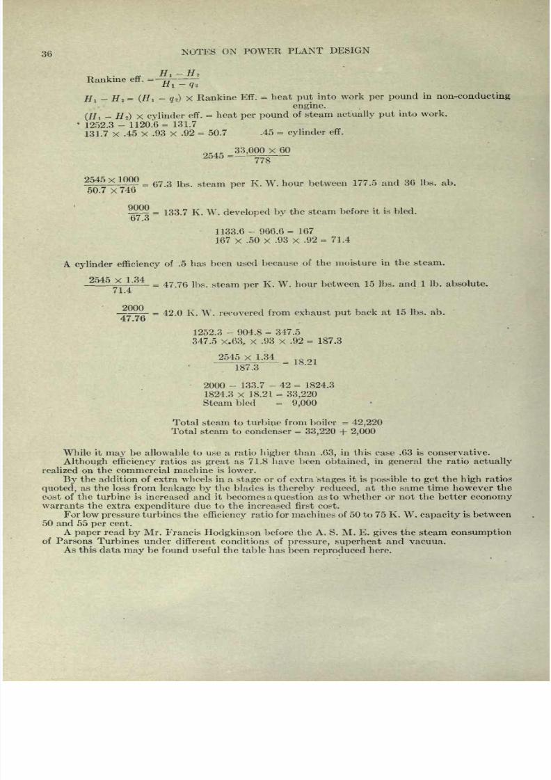
8/20/2019 notes on powerplant.pdf
http://slidepdf.com/reader/full/notes-on-powerplantpdf 42/202
36
NOTES
ON
POWER
PLANT
DESIGN
Rankine
eff.
=
77
it-
1
</2
Hi
-
#
2
=
(Hi
-
g
2
)
X
Rankine
Eff.
=
heat
put
into
work
per
pound
in
non-conducting
engine.
(#,
-
#>)
X
cylinder
eff.
=
heat
per
pound
of
steam
actually
put
into
work.
'
1252.3
- 1120.6=
131.7
131.7
x
.45
X
.93
X
.92
=
50.7
.45
=
cylinder
eff.
33,000
X
60
2545
=
^TO
2545^1^00
=
6?
3
lbg
steam
K w
hour between
177.5
and
36
Ibs.
ab.
50.7
x
746
33.7
K. W.
developed
by
the
steam
before
it is bled.
67.3
1133.6
-966.6=
167
167
x
.50
x
.93
x
.92
=
71.4
A.
cylinder
efficiency
of
.5 has
been
used
because
of the moisture
in
the
steam.
_2M5_x_L34_
=
lb
gteam
K
w
hour
between
15
j
bs< an(
j
i
ib.
absolute.
71.4
2000
-
=
42.0
K.
W.
recovered
from
exhaust
put
back
at
15 Ibs.
ab.
47.7o
1252.3
-
904.8
=
347.5
347.5
x.63,
x
.93
x
.92
=
187.3
2545
x
1.34
~18773~
2000
-
133.7
-
42
=
1824.3
1824.3
x
18.21
=
33,220
Steam
bled
=
9,000
Total steam to
turbine
from boiler
=
42,220
Total steam to
condenser
=
33,220
+
2,000
While
it
may
be allowable to use a ratio
higher
than
.63,
in
this case .63
is
conservative.
Although
efficiency
ratios
as
great
as
71.8 have
been
obtained,
in
general
the
ratio
actually
realized
on
the commercial machine
is
lower.
By
the
addition
of
extra
wheels
in a
stage
or
of
extra
'stages
it
is
possible
to
get
the
high
ratios
quoted,
as
the loss
from
leakage
by
the
blades
is
thereby
reduced,
at
the same
time
however
the
cost
of
the
turbine
is increased
and
it
becomes
a
question
as
to
whether
or not the
better
economy
warrants the
extra
expenditure
due
to
the increased first cost.
For
low
pressure
turbines the
efficiency
ratio for
machines
of
50 to
75
K. W.
capacity
is
between
50
and
55
per
cent.
A
paper
read
by
Mr. Francis
Hodgkinson
before
the
A. S.
M.
E.
gives
the
steam
consumption
of
Parsons
Turbines under
different
conditions of
pressure,
superheat
and
vacuua.
As
this
data
may
be found
useful
the
table
has
been
reproduced
here.
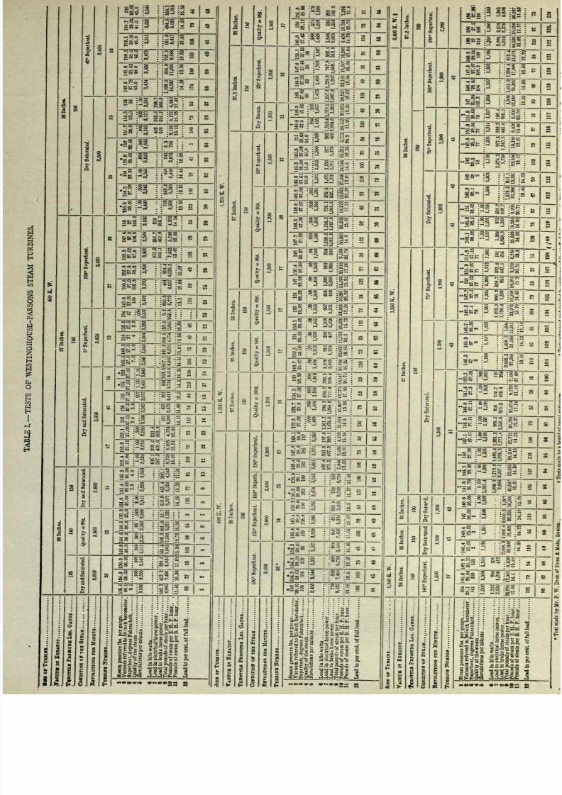
8/20/2019 notes on powerplant.pdf
http://slidepdf.com/reader/full/notes-on-powerplantpdf 43/202
3
IS
i
g
II
a5
:^S
S5
:S^.
:
P
I
i2
* *
Z^fff
2*
IVjj
;
w
I
eo
;&&
2
*>?
T ??
S
5
5
SS
=S
jj^
-^
S 9
132
:3
w .mt-
-
-OHO
$7
:
^
i^-
'cc i3
iS^ i
JI15
.
S8
:
:
E
S
O
-05
0.
-fft
'
SS
:s
tes its
:
=
woo
-2
<~t-
...
.J5
a,,.
:
8 S
|lp gP
:
S
3
wS '^S
lisi
:
*
O
CO
vt
*^
^
O
-
'
Ji
i
.
i*
iw i
B
i
*KS
:o^
:
*
I
.
.
8S2
:ft
3$:21
2
I-
.
jjs
: I a
oogg
:8
:
:*.~
:R
?a
P
j
:s5
ja
s
s
583
:
j
|Q
a
'388
p
2g
:*3
i
s
5
;atf .
=5
-s
:8S
'
t-^
:s
So
;
-
-8
:8S
'-.
:gc
:~
>2
8
:-3
5
ISl
i
6
5
SfcBalSn
sis
jga
i
3
I
1
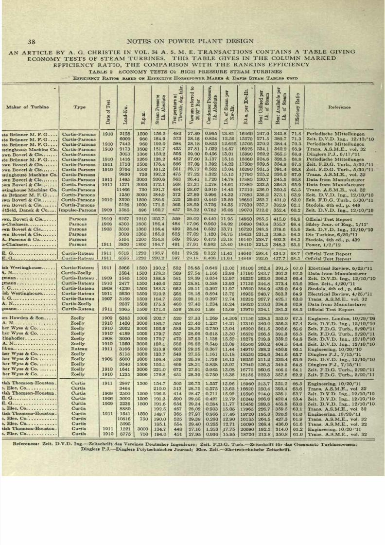
8/20/2019 notes on powerplant.pdf
http://slidepdf.com/reader/full/notes-on-powerplantpdf 44/202
38
NOTES
ON
POWER
PLANT
DESIGN
AN
ARTICLE
BY A. G.
CHRISTIE
IN
VOL. 34
A.
S.
M.
E. TRANSACTIONS
CONTAINS
A
TABLE
GIVING
ECONOMY
TESTS OF
STEAM
TURBINES.
THIS
TABLE
GIVES
IN THE COLUMN MARKED
EFFICIENCY
RATIO,
THE
COMPARISON
WITH THE
RANKINS
EFFICIENCY
TABUS
2
ECONOMY
TESTS Ol
HIGH PRESSURE STEAM
TURBINES
EFFICIENCY
RATIOS BASED
ON
EFFECTIVE
HORSEPOWER
MARKS
&
DAVIS
STEAM
TABLES
USED
Maker
of Turbine
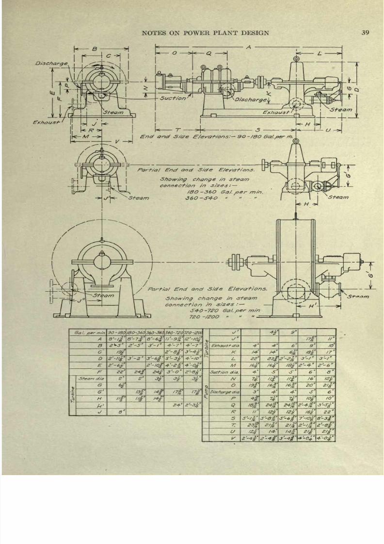
8/20/2019 notes on powerplant.pdf
http://slidepdf.com/reader/full/notes-on-powerplantpdf 45/202
NOTES
ON
POWER
PLANT DESIGN
A
39
Discharge
9O
~/8O
Ga/.per
rh
Port/a/
End
and
Side
E/erations,
Showing
change
in steam
connection in
sizes:
/8O
-36O
6aj.
per
min.
36O-S40
/
Partial
End
and
Side
Showing
change
in
-si-earn
connection
in
sizes
:
S4-O
-72O
Ga/.
per
min
72O
-/2OO
Ga/.
per
m/n.
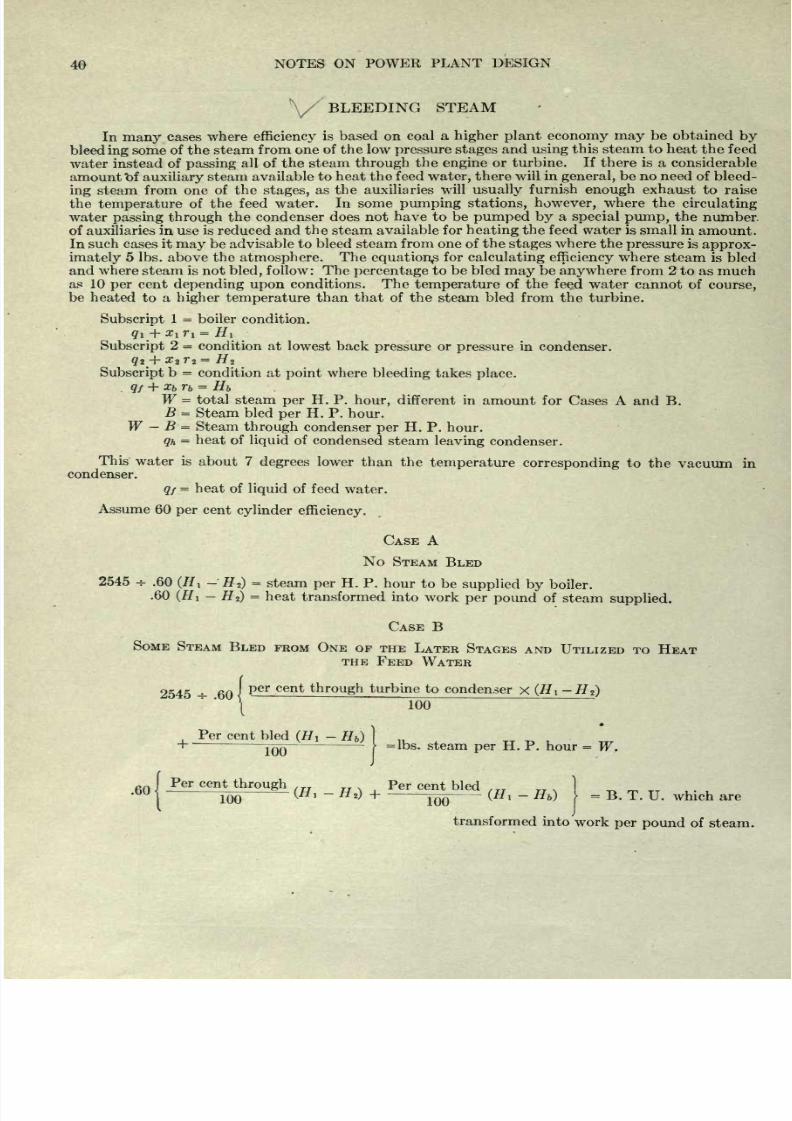
8/20/2019 notes on powerplant.pdf
http://slidepdf.com/reader/full/notes-on-powerplantpdf 46/202
40
NOTES ON
POWER
PLANT
DESIGN
BLEEDING
STEAM
In
many
cases
where
efficiency
is
based
on
coal a
higher
plant
economy
may
be
obtained
by
bleed
ing
some
of
the
steam
from one
of
the low
pressure
stages
and
using
this
steam
to heat
the
feed
water
instead
of
passing
all
of
the
steam
through
the engine
or
turbine.
If
there
is
a
considerable
amount
t>f
auxiliary
steam
available
to heat the
feed
water,
there
will in
general,
be
no
need of
bleed-
ing
steam
from one
of
the
stages,
as
the auxiliaries
will
usually
furnish
enough
exhaust to raise
the
temperature
of
the
feed water.
In
some
pumping
stations,
however,
where
the
circulating
water
passing
through
the
condenser
does
not
have
to be
pumped
by
a
special
pump,
the
number.
of
auxiliaries
in
use is
reduced
and
the
steam available
for
heating
the feed water is
small in
amount.
In
such
cases it
may
be advisable to
bleed
steam
from
one
of the
stages
where
the
pressure
is
approx-
imately
5 Ibs.
above
the
atmosphere.
The
equation^
for
calculating
efficiency
where steam
is bled
and where
steam
is
not
bled,
follow: The
percentage
to
be bled
may
be
anywhere
from
2
to as
much
as 10
per
cent
depending upon
conditions.
The
temperature
of
the
feed
water
cannot
of
course,
be
heated
to
a
higher
temperature
than
that
of
the
steam bled from
the
turbine.
Subscript
1
=
boiler
condition.
qi
+
XiTi
=
Hi
Subscript
2
=
condition at
lowest back
pressure
or
pressure
in
condenser.
Subscript
b
=
condition at
point
where
bleeding
takes
place.
qf
+
x
b
r
b
=
Hb
W
=
total
steam
per
H. P.
hour,
different in
amount
for
Cases A
and B.
B
=
Steam
bled
per
H.
P.
hour.
W
B
=
Steam
through
condenser
per
H. P.
hour.
qh
=
heat
of
liquid
of
condensed
steam
leaving
condenser.
This
water is
about
7
degrees
lower
than the
temperature
corresponding
to
the
vacuum
in
condenser.
q/
=
heat
of
liquid
of
feed
water.
Assume
60
per
cent
cylinder
efficiency.
CASE
A
No
STEAM
BLED
2545
*
.60
(Hi
-
H
2
)
=
steam
per
H.
P.
hour
to
be
supplied
by
boiler.
.60
(Hi
-
HJ
=
heat
transformed
into
work
per
pound
of
steam
supplied.
CASE
B
SOME
STEAM
BLED
FROM ONE
OF
THE
LATER
STAGES
AND
UTILIZED TO
HEAT
THE
FEED
WATER
2545
-
60
J
per
Cent
through
turD
ine
to
condenser
x
(#1
-#
2
)
\
100
Per
cent
bled
(Hi
-
H
b
)
}
JQQ
-
f
=lbs.
steam
per
H.
P.
hour
=
W.
60 I
Per
cent
through
Per
cent
bled
,
1
100
'
\
Hl
~
Hi)
+
-
-^OQ
--
(H
l
-
H
b
)
=
B.
T.
U.
which are
transformed
into
work
per
pound
of
steam.
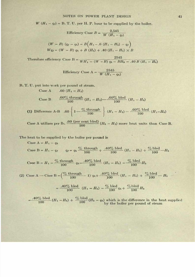
8/20/2019 notes on powerplant.pdf
http://slidepdf.com/reader/full/notes-on-powerplantpdf 47/202
8/20/2019 notes on powerplant.pdf
http://slidepdf.com/reader/full/notes-on-powerplantpdf 48/202
42
NOTES
ON
POWER
PLANT
DESIGN
GENERAL
DIMENSIONS
OF
ENGINES
Tables
of
cylinder
sizes,
horse
power
and
overall
dimensions
of
a number
of
different
engines
are
given
on
the
pages
following.
The
engines
shown
are
each
typical
of
a
class
and
have
been
selected
with
this
in mind
only.
In
general
the
single
cylinder
engines
are rated
on
a
cut-off
at
about
one
quarter
stroke.
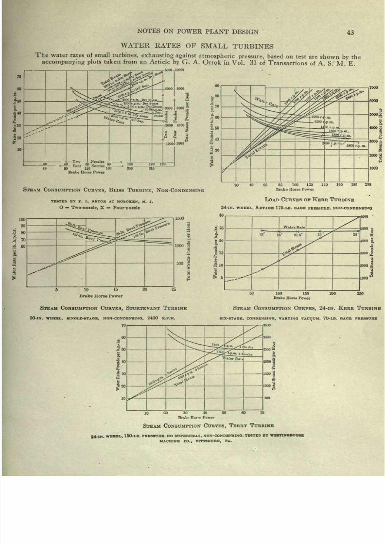
8/20/2019 notes on powerplant.pdf
http://slidepdf.com/reader/full/notes-on-powerplantpdf 49/202
NOTES
ON
POWER
PLANT
DESIGN
43
WATER
RATES
OF
SMALL
TURBINES
The water rates
of
small
turbines,
exhausting
against
atmospheric
pressure,
based
on
test
are
shown
by
the
accompanying
plots
taken
from an
Article
by
G.
A.
Orrok
in
Vol.
31
of
Transactions
of
A. S.
M.
E.
r-5000-,
10000
120
160
Brake
Horse
Power
STEAM
CONSUMPTION
CURVES,
BLISS
TURBINE,
NON-CONDENSING
40
60 80
100
120 143
Brake
Horse
Power
160 180
200
TESTED BY
P. L.
PRYOR AT
HOBOKEN,
N. JT.
O
=
Two-nozzle,
X
=
Four-nozzle
LOAD
CURVES OF
KERR
TURBINE
24-IN.
WHEEL,
8-STAOE 175-LB.
OAQE
PRESSURE,
NON-CONOEN8INO
1500
10
15
Brake
Horse
Power
Water
R
per
h.p_-hr.
S
8
8
j
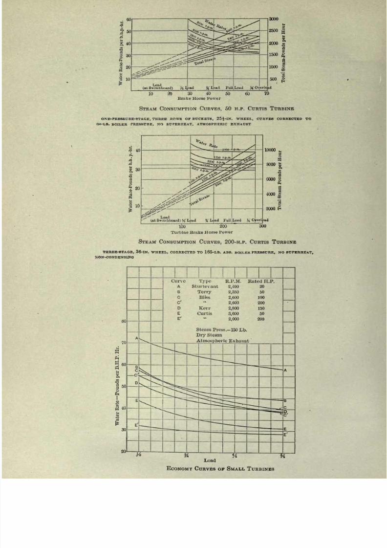
8/20/2019 notes on powerplant.pdf
http://slidepdf.com/reader/full/notes-on-powerplantpdf 50/202
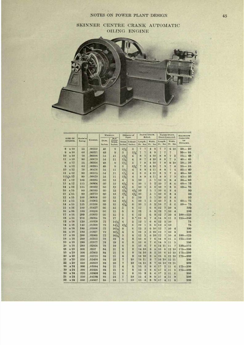
8/20/2019 notes on powerplant.pdf
http://slidepdf.com/reader/full/notes-on-powerplantpdf 51/202
NOTES
ON
POWER
PLANT
DESIGN
45
SKINNER
CENTRE
CRANK
AUTOMATIC
OILING
ENGINE
SIZE OF
ENGINE.
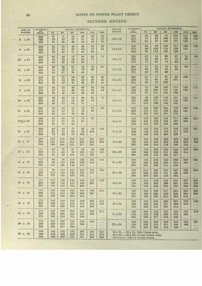
8/20/2019 notes on powerplant.pdf
http://slidepdf.com/reader/full/notes-on-powerplantpdf 52/202
46
NOTES
ON POWER
PLANT
DESIGN
SKINNER
ENGINE
SIZE OF
ENGINE.
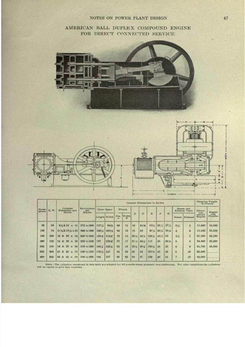
8/20/2019 notes on powerplant.pdf
http://slidepdf.com/reader/full/notes-on-powerplantpdf 53/202
NOTES
ON
POWER
PLANT
DESIGN
47
AMERICAN BALL
DUPLEX
COMPOUND ENGINE
FOR
DIRECT
CONNECTED SERVICE
H
J
Horse-
power
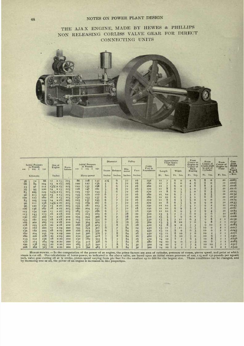
8/20/2019 notes on powerplant.pdf
http://slidepdf.com/reader/full/notes-on-powerplantpdf 54/202
48
NOTES
ON
POWER
PLANT
DESIGN
THE
AJAX
ENGINE,
MADE
BY
HEWES
&
PHILLIPS
NON
RELEASING
CORLISS
VALVE
GEAR
FOR
DIRECT
CONNECTING
UNITS
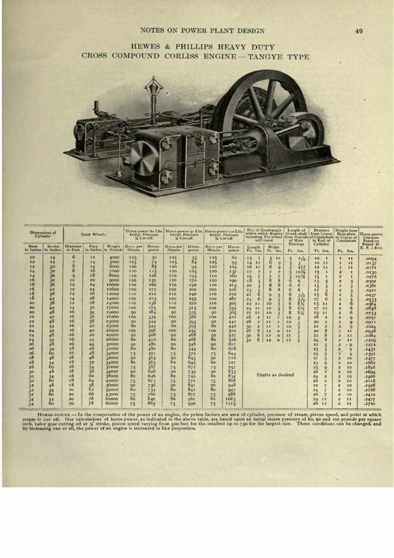
8/20/2019 notes on powerplant.pdf
http://slidepdf.com/reader/full/notes-on-powerplantpdf 55/202
NOTES
ON
POWER
PLANT
DESIGN
49
HEWES
&
PHILLIPS
HEAVY
DUTY
CROSS
COMPOUND
CORLISS
ENGINE
TANGYE
TYPE
Dimensions
of
Cylinder
'
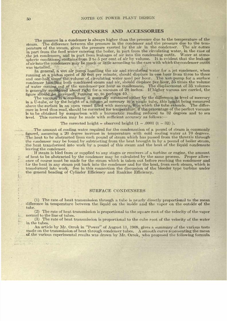
8/20/2019 notes on powerplant.pdf
http://slidepdf.com/reader/full/notes-on-powerplantpdf 56/202
50
CONDENSERS
AND
ACCESSORIES
The
pressure
in a
Condenser
is
always
higher
than
the
pressure
due to the
temperature
of
the
steam.
The
difference
between
the
pressure
in
the
condenser
and the
pressure
due
to
the
tem-
perature
of the
steam,
gives
the
pressure
exerted
by
the
air
in
the
condenser. The air
comes
in
part
from
the
feed
water
entering
the boiler,
in
part
from
the
circulating
water,
in
the
case
of
the
jet
condensers,
and
in
part
from
leakages
of
air
into the
condensing
outfit. Water
at
atmo-
'spheric
conditions,
contains
from
2
to
5
per
cent of
air
by
volume.
It is evident
that
the
leakage
of
air
into
the
condensers
may
be much
or
little
according
to
the
care with
which
the condenser outfit
was
installed.
In
general,
a
wet
air
pump
handling
the
air and
circulating
water for a
jet
condenser,
when
running
at a
piston
speed
of
SO
feet
per
minute,
should
displace
in
one hour
from three to three
and
one-half
times'
thes,
volume of
circulating
water used
per
hour.
The
wet
pump
for
a
surface
condenser
haridrfng
both
condensed
steam
and
air,
should
displace
per
hour,
35
times
the volume
of
water
coming,
out
of
the
condenser-per
hour
as
condensate.
The
displacement
of 35 volumes
is
generally
considered
about
right
for
a vacuum
of
28
inches.
If
higher
vacuua
are
carried,
the
figure
should
be
increased,
running
up
to
.perhaps
40.
The
vacuum'iri
a
condenser
is
generally
measured either
by
the difference
in level
of
mercury
in
a
U-tube,
or
by
the
height
of
a
column
of
mercury
in
A
single
tube,
.this
height
being
measured
above
the surface
in
an
open
vessel
filled
with
mercury,
into
which
the tube
extends.
The differ-
ence in
level thus
read,
should
be
corrected
for
temperature,
if
the
percentage
of the
perfect
vacuum
is
to
be
obtained
by
comparison
with
a
barometric
reading
reduced to
32
degrees
and
to
sea
level. This correction
may
be
made with
sufficient
accuracy
as
follows
:
The
corrected
height
=
observed
height
(1
-
.0001
(t
-
32)
).
The amount
of
cooling
water
required
for
the
condensation
of
a
pound
of
steam
is
commonly
figured,
assuming
a
20
degree
increase in
temperature
with
cold
cooling
water
at
70
degrees.
The
heat
to
be abstracted
from
each
pound
of steam
which
has
passed
from the throttle
through
the
condenser
may
be
found
by
subtracting
from the
heat
brought
in
by
a
pound
of
boiler
steam,
_the heat
transformed
into
work
by
a
pound
of
this
steam
and
the
heat
of the
liquid
condensate
leaving
the
condenser.
If
steam
is
bled
from
or
supplied
to
any
stages or receivers
of
a
turbine
or engine,
the
amount
of
heat
to
be
abstracted
by
the condenser
may
be
calculated
by
the
same
process. Proper
allow-
ance of
course
must
be
made
for
the
steam which
is
taken
out before
reaching
the condenser
and
for the heat
in
any
steam
put
back into the
condenser
and
for
the
heat,
from
such
steam,
which
is
transformed into
work. See
in
this
connection
the
discussion
of
the
bleeder
type
turbine
under
the
general
heading
of
Cylinder
Efficiency
and Rankine
Efficiency.
SURFACE CONDENSERS
(1)
The
rate
of heat
transmission
through
a
tube
is
nearly
directly
proportional
to the
mean
difference
in
temperature
between
the
liquid
on
the
inside
and
the
vapor
on
the
outside
of
the
tube.
(2)
The
rate
of
heat
transmission
is
proportional
to the
square
root of
the
velocity
of the
vapor
j>
r
normal
to
the
line of
tubes.
(3)
The
rate
of
heat
transmission
is
proportional
to the
cube
root
of
the
velocity
of the water
in
the
tubes.
An
article
by
Mr. Orrok
in
Power
of
August 11,
1908, gives
a
summary
of
the
various
tests
made
on
the
transmission
of heat
through
condenser
tubes. A
smooth
curve
representing
the
mean
of
the
various
experimental
results
was
drawn
by
Mr.
Orrok,
who
proposed
the
following
formula
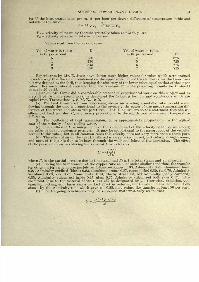
8/20/2019 notes on powerplant.pdf
http://slidepdf.com/reader/full/notes-on-powerplantpdf 57/202
NOTES ON
POWER
PLANT DESIGN
51
for U
the
heat
transmission
per
sq.
it.
per
hour
per
degree
difference of
temperature
inside
and
outside of
the
tube:
3
_
=
17
VV
8
V.023
+
V
w
V
s
=
velocity
of steam
by
the tube
generally
taken
as
625
ft.
p.
sec.
V
w
=
velocity
of
water in
tube
in
ft.
per
sec.
Values
read from the curve
give
Vel. of
water
in
tubes
U Vel. of
water
in tubes
in
ft.
per
second. in
ft.
per
second.
U
.5
350
4
675
1
430
5 725
2
545
6
775
3
620 7
815
Experiments by
Mr.
E.
Josse have shown
much
higher
values
for
tubes
which
were drained
in such
a
way
that the
steam condensed on
the
upper
rows
did not
trickle down
over
the lower
rows
but
was drained
to
the
shell,
thus
keeping
the
efficiency
of the
lower
tubes
equal
to
that of the
upper
tubes.
For
such tubes
it
appeared
that
the
constant
17
in
the
preceding
formula
for U should
be
made
20
or
25.
Later
on
Mr.
Crrok
did
a
considerable
amount of
experimental
work
on
this
subject
and
as
a result of
his
more
recent work
he
developed
the
following
formula
and
conclusions
which
are
copied
from
Transactions
A.
S. M.
E.,
1910.
(a)
The
heat
transferred
from
condensing
steam
surrounding
a
metallic
tube to cold
water
flowing through
the
tube is
proportional
to the
seven-eighths
power
of
the mean
temperature
dif-
ference of
the
water and
steam
temperatures.
This
is
equivalent
to
the
statement
that
the
co-
efficient
of heat
transfer,
U,
is
inversely
proportional
to the
eighth
root of
the mean
temperature
difference.
(b)
The
coefficient
of heat
transmission,
U,
is
approximately
proportional
to
the
square
root of
the
velocity
of
the
cooling
water.
(c)
The
coefficient U is
independent
of
the
vacuum
and
of
the
velocity
of the steam
among
the
tubes or
in the
condenser
passages.
It
may
be
proportional
to the
square
root
of the
velocity
normal
to
the
tubes,
but
in
all
common
cases
this
velocity
does not
vary
more
than
a
tenth
part.
(d)
The
effect
of
air
on
the heat
transferred
is
very
marked
indeed, particularly
at
high vacuua,
and most of this
air
is due
to
leakage
through
the
walls and
joints
of the
apparatus.
The
effect
of
the
presence
of air in
reducing
the
value
of
U
is
as
follows:
where P
8
is
the
partial
pressure
due
to the
steam
and
P
t
is
the
total
steam
and
air
pressure.
(e) Taking
the
heat transfer of
the
copper
tube as 1.00
under
similar
conditions
the
transfer
for
other
materials is
approximately
as
follows:
copper,
1.00,
Admirality
0.93,
aluminum
lined
0.97,
Admiralty
oxidized
(black)
0.92,
aluminum-bronze
0.87, cupro-nickel
0.80,
tin
0.79,
Admiralty
lead-lined
0.79,
zinc
0.75,
Monel
metal
0.74,
Shelby
steel
0.63,
old
Admiralty
(badly
corroded)
0.55,
Admiralty
vulcanized
inside
0.47,
glass
0.25,
Admiralty
vulcanized
both sides
0.17.
This
coefficient
(due
to
the
material
of
the
tube)
will
be
designated
by
/*. Corrosion,
oxidation,
vul-
canizing,
pitting,
etc.,
have
also
a
marked
effect in
reducing
the
transfer.
This
reduction,
best
shown
by
the
Admiralty
tube
which
gave
pi
=
0.55,
may
reduce
the
transfer
at
least
50
per
cent.
(f)
The
foregoing
conclusions
may
be
expressed
mathematically
as
follows:
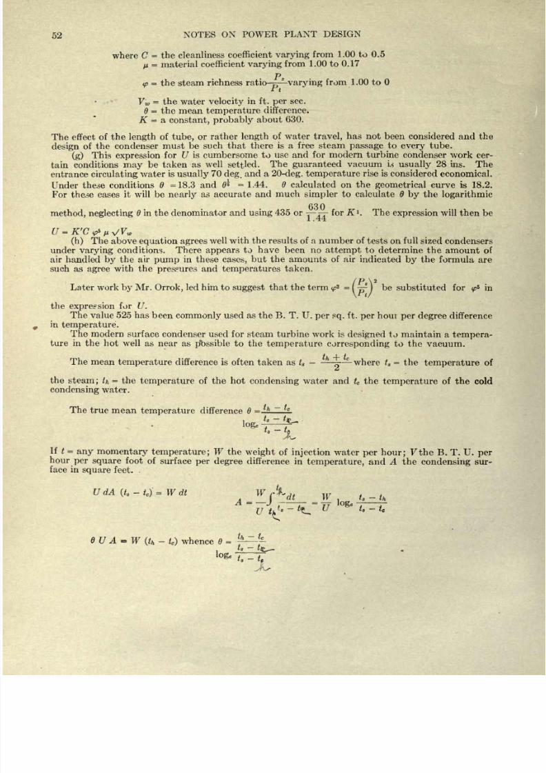
8/20/2019 notes on powerplant.pdf
http://slidepdf.com/reader/full/notes-on-powerplantpdf 58/202
52
NOTES
ON
POWER
PLANT
DESIGN
where
C
=
the
cleanliness
coefficient
varying
from 1.00
to
0.5
n
=
material
coefficient
varying
from
1.00
to
0.17
p
<p
=
the steam
richness
ratio-^
varying
from 1.00 to
t
V
w
=
the
water
velocity
in
ft.
per
sec.
=
the mean
temperature
difference.
K
=
a
constant,
probably about
630.
The
effect of
the
length
of
tube,
or
rather
length
of water
travel,
has not been
considered and the
design
of
the condenser
must be
such
that
there
is a free steam
passage
to
every
tube.
(g)
This
expression
for U is
cumbersome
to
use
and
for modern
turbine
condenser
work cer-
tain
conditions
may
be taken
as well
settled.
The
guaranteed
vacuum
U
usually
28
ins.
The
entrance
circulating
water
is
usually
70
deg.
and a
20-deg.
temperature
rise
is
considered
economical.
Under
these conditions
=18.3
and
0*
=
1.44.
calculated
on the
geometrical
curve
is 18.2.
For
these cases
it
will be
nearly
as
accurate
and much
simpler
to
calculate
by
the
logarithmic
O
/ i
method,
neglecting
in the denominator
and
using
435 or
^~rr
for K
l
. The
expression
will
then be
(h)
The
above
equation
agrees
well
with the results of
a
number of
tests on full
sized
condensers
under
varying
conditions. There
appears
to
have
been no
attempt
to determine
the
amount
of
air
handled
by
the
air
pump
in
these
cases,
but the amounts
of air
indicated
by
the
formula
are
such
as
agree
with the
pressures
and
temperatures
taken.
/p
\2
Later work
by
Mr.
Orrok,
led
him to
suggest
that the
term
<^
2
=
I
-~
I
be
substituted for
<p*
in
\rt/
the
expression
for
U.
The
value
525
has
been
commonly
used
as
the
B.
T. U.
per sq.
ft.
per
hour
per degree
difference
in
temperature.
The
modern
surface
condenser used for
steam
turbine work
is
designed
to maintain
a
tempera-
ture
in
the hot
well
as
near
as
possible
to
the
temperature
corresponding
to the
vacuum.
The
mean
temperature
difference is
often taken as t
s
-
where
t
s
=
the
temperature
of
a
the
steam;
th
=
the
temperature
of
the hot
condensing
water
and
t
c
the
temperature
of
the
cold
condensing
water.
The
true
mean
temperature
difference
=
h
~
c
loge
-
~JL
If
t
=
any
momentary temperature;
W
the
weight
of
injection
water
per hour;
Fthe
B.
T.
U.
per
hour
per
square
foot
of
surface
per
degree
difference
in
temperature,
and
A
the
condensing
sur-
face
in
square
feet.
u
dA
(t
s
-
g
-
w
dt
w
A
,
w
A
-
-
W
s
~
h
.
J
f
t
~
TT
IO
e
e
~t ~T
u
tk
~
^-
u
ts
~
te
-
Q
whence
=
^
t
s
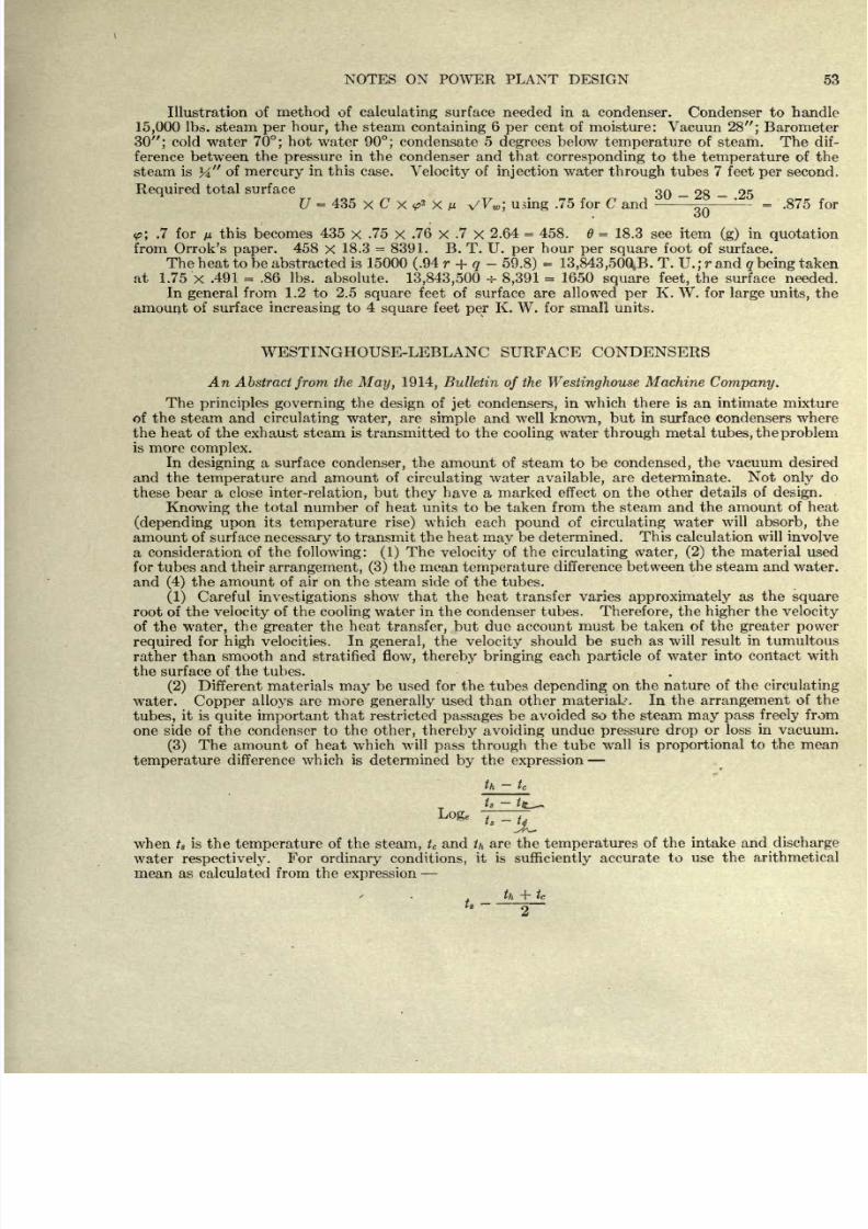
8/20/2019 notes on powerplant.pdf
http://slidepdf.com/reader/full/notes-on-powerplantpdf 59/202
NOTES
ON
POWER PLANT
DESIGN
53
Illustration of
method
of
calculating
surface
needed
in
a condenser.
Condenser
to
handle
15,000
Ibs.
steam
per hour,
the
steam
containing
6
per
cent of
moisture:
Vacuun
28 ;
Barometer
30 ;
cold
water
70;
hot
water
90;
condensate
5
degrees
below
temperature
of steam.
The
dif-
ference
between
the
pressure
in
the
condenser
and
that
corresponding
to the
temperature
of the
steam
is
J4
of
mercury
in this
case.
Velocity
of
injection
water
through
tubes 7 feet
per
second.
Required
total
surface
qn 98
_
tt
U
=
435
x
C
x
<P*
X
A
W
w
;
using
.75
for C
and
-
*
=
.875
for
.
oU
<t>\
.7 for
fj.
this
becomes
435
x
.75
x
.76
X
.7
x
2.64
=
458.
=
18.3
see
item
(g)
in
quotation
from Orrok's
paper.
458
X
18.3
=
8391.
B.
T.
U.
per
hour
per
square
foot
of surface.
The heat
to
be abstracted
is
15000
(.94
r
+
q
-
59.8)
=
13,843,500.6.
T.
U.;
r
and
q
being
taken
at
1.75
X
.491
=
.86
Ibs.
absolute.
13,843,500
-=-
8,391
=
1650
square feet,
the
surface
needed.
In
general
from 1.2
to
2.5
square
feet
of surface are
allowed
per
K. W. for
large
units,
the
amount
of
surface
increasing
to
4
square
feet
per
K.
W.
for
small
units.
WESTINGHOUSE-LEBLANC
SURFACE
CONDENSERS
An
Abstract
from
the
May,
1914,
Bulletin
of
the
Westinghouse
Machine
Company.
The
principles
governing
the
design
of
jet
condensers,
in which
there is
an intimate
mixture
of the
steam
and
circulating
water,
are
simple
and
well
known,
but
in
surface
condensers
where
the
heat
of the
exhaust
steam
is
transmitted
to
the
cooling
water
through
metal
tubes,
the
problem
is more
complex.
In
designing
a
surface
condenser,
the amount of steam to
be
condensed,
the
vacuum
desired
and the
temperature
and
amount
of
circulating
water
available,
are
determinate.
Not
only
do
these
bear
a close
inter-relation,
but
they
have
a
marked effect
on
the
other
details
of
design.
Knowing
the
total number of heat
units
to
be
taken from
the
steam
and
the amount
of
heat
(depending
upon
its
temperature
rise)
which
each
pound
of
circulating
water
will
absorb,
the
amount of
surface
necessary
to
transmit
the
heat
may
be determined. This
calculation
will
involve
a consideration of
the
following:
(1)
The
velocity
of
the
circulating
water,
(2)
the material
used
for
tubes and their
arrangement, (3)
the
mean
temperature
difference
between
the
steam
and
water,
and
(4)
the
amount
of
air
on
the
steam
side of
the
tubes.
(1)
Careful
investigations
show
that
the
heat
transfer
varies
approximately
as the
square
root of
the
velocity
of
the
cooling
water in
the
condenser
tubes.
Therefore,
the
higher
the
velocity
of the
water,
the
greater
the heat
transfer,
but due account
must be taken of the
greater power
required
for
high
velocities.
In
general,
the
velocity
should
be such
as
will
result
in tumultous
rather than
smooth and stratified
flow, thereby
bringing
each
particle
of water
into
contact with
the
surface of the
tubes.
(2)
Different
materials
may
be
used
for
the
tubes
depending
on
the nature of the
circulating
water.
Copper
alloys
are more
generally
used than other
materials.
In the
arrangement
of the
tubes,
it
is
quite
important
that
restricted
passages
be
avoided
so the steam
may
pass
freely
from
one
side of
the
condenser
to
the
other,
thereby
avoiding
undue
pressure
drop
or loss
in
vacuum.
(3)
The
amount of heat which will
pass through
the
tube wall
is
proportional
to
the
mean
temperature
difference
which
is
determined
by
the
expression
th
t
c
ts-
Loge
^
^
J#
when
t
s
is
the
temperature
of the
steam,
t
c
and
th
are the
temperatures
of
the
intake
and
discharge
water
respectively.
For
ordinary
conditions,
it is
sufficiently
accurate
to use
the
arithmetical
mean
as
calculated
from
the
expression
ts
n
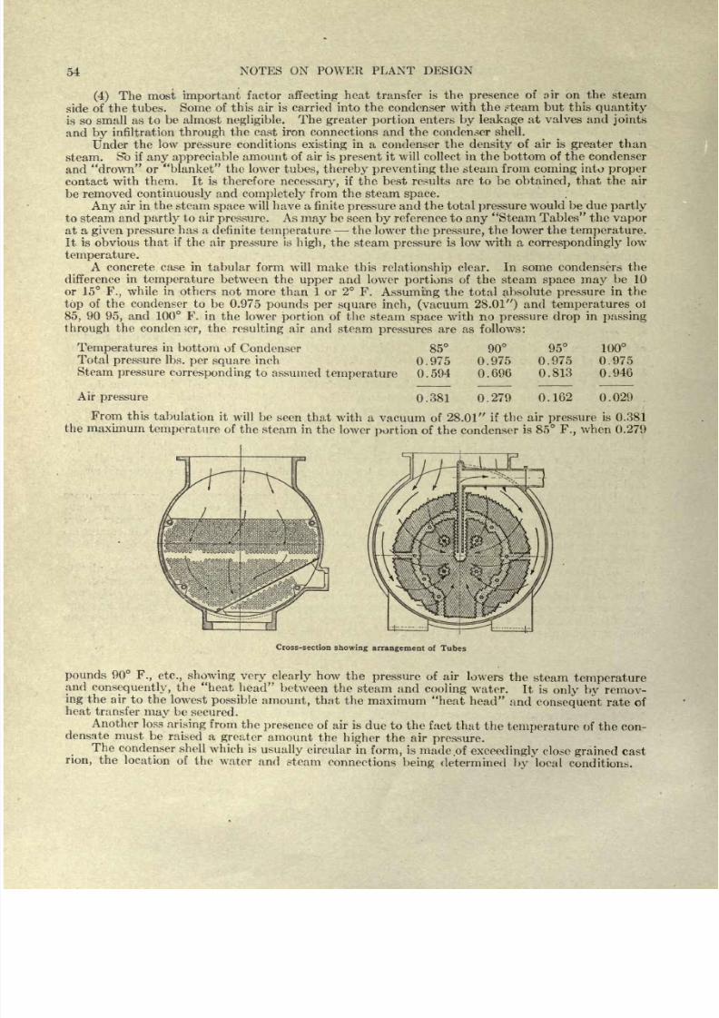
8/20/2019 notes on powerplant.pdf
http://slidepdf.com/reader/full/notes-on-powerplantpdf 60/202
54
NOTES
ON
POWER
PLANT
DESIGN
(4)
The
most
important
factor
affecting
heat
transfer
is the
presence
of
air
on
the
steam
side
of the
tubes.
Some of this
air is carried into
the
condenser with
the ?team
but this
quantity
is
so
small
as
to
be almost
negligible.
The
greater
portion
enters
by
leakage
at
valves
and
joints
and
by
infiltration
through
the
cast
iron
connections
and
the
condenser
shell.
Under
the
low
pressure
conditions
existing
in
a
condenser the
density
of
air
is
greater
than
steam.
So
if
any
appreciable
amount
of air
is
present
it will collect in
the
bottom
of
the
condenser
and
drown
or
blanket the
lower
tubes,
thereby
preventing
the steam
from
coming
into
proper
contact
with
them.
It is
therefore
necessary,
if
the
best
results
are
to
be
obtained,
that the
air
be
removed
continuously
and
completely
from
the
steam
space.
Any
air
in
the
steam
space
will
have
a
finite
pressure
and
the
total
pressure
would
be
due
partly
to
steam
and
partly
to
air
pressure.
As
may
be
seen
by
reference to
any
Steam Tables the
vapor
at
a
given
pressure
has
a
definite
temperature
the lower the
pressure,
the lower
the
temperature.
It is obvious
that
if
the
air
pressure
is
high,
the steam
pressure
is
low
with
a
correspondingly
low
temperature.
A
concrete
case
in
tabular form
will make
this
relationship
clear.
In some
condensers
the
difference
in
temperature
between the
upper
and
lower
portions
of
the steam
space
may
be
10
or
15
F.,
while in
others
not more
than
1
or
2
F.
Assuming
the
total
absolute
pressure
in
the
top
of the
condenser to
be
0.975
pounds
per
square
inch, (vacuum
28.01 )
and
temperatures
of
85,
90
95,
and 100
F.
in
the
lower
portion
of the
steam
space
with no
pressure
drop
in
passing
through
the
condenser,
the
resulting
air
and
steam
pressures
are as
follows:
Temperatures
in
bottom of
Condenser
Total
pressure
Ibs.
per
square
inch
Steam
pressure
corresponding
to
assumed
temperature
85
0.975
0.594
90
0.975
0.696
95
100
0.975
0.975
0.813 0.946
Air
pressure
0.381
0.279
0.162
0.029
From
this
tabulation
it will
be
seen
that
with a
vacuum
of
28.01
if
the
air
pressure
is
0.381
the
maximum
temperature
of
the steam
in
the lower
portion
of the condenser
is
85
F.,
when 0.279
Cross-section
showing arrangement
of
Tubes
pounds
90
F.,
etc., showing
very
clearly
how
the
pressure
of
air
lowers
the
steam
temperature
and
consequently,
the heat
head
between
the
steam
and
cooling
water.
It
is
only
by
remov-
ing
the
air to
the
lowest
possible
amount,
that
the
maximum
heat
head
and
consequent
rate
of
heat
transfer
may
be
secured.
Another
loss
arising
from
the
presence
of
air
is
due
to the
fact
that
the
temperature
of
the
con-
densate
must
be
raised
a
greater
amount
the
higher
the
air
pressure.
The
condenser
shell
which
is
usually
circular
in
form,
is
made of
exceedingly
close
grained
cast
rion,
the
location of
the
water
and
steam
connections
being
determined
by
local
conditions.
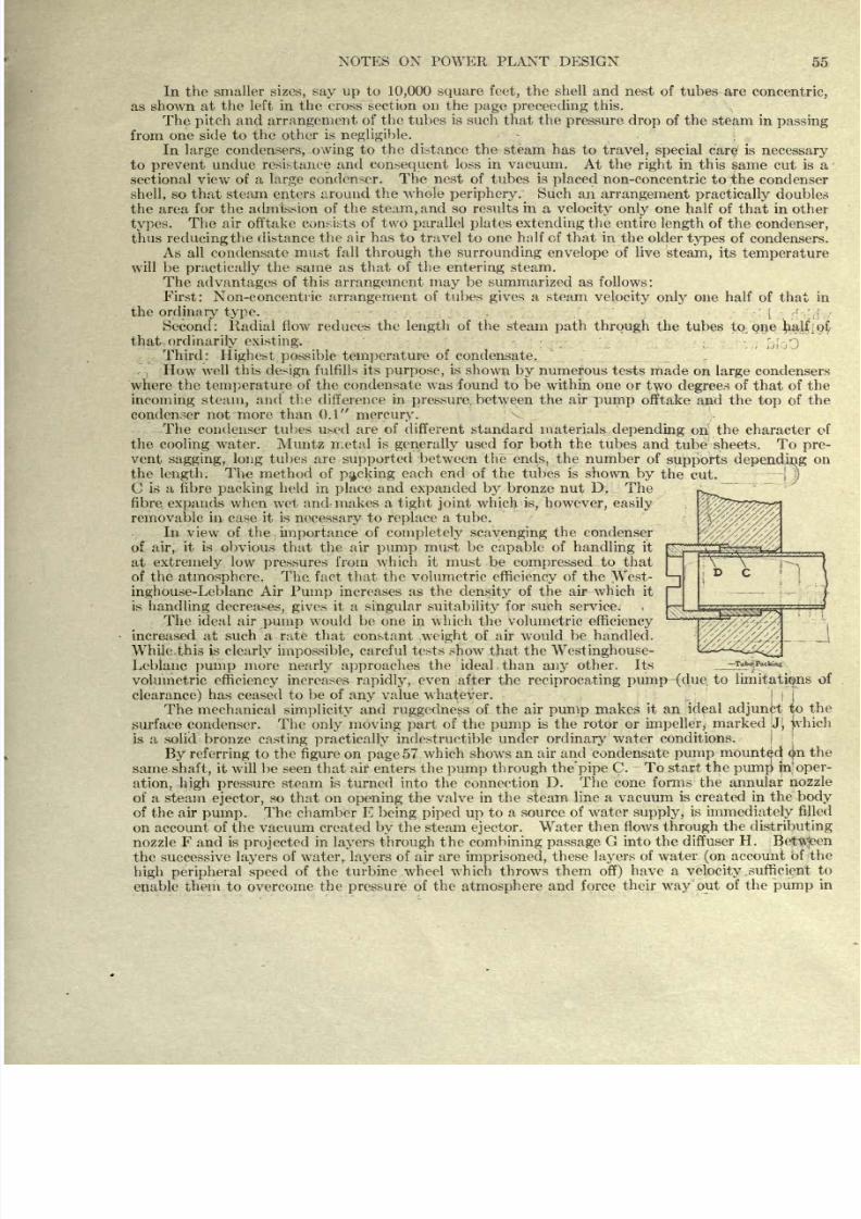
8/20/2019 notes on powerplant.pdf
http://slidepdf.com/reader/full/notes-on-powerplantpdf 61/202
In the smaller
sizes,
say
up
to
10,000
square
feet,
the shell
and
nest
of
tubes
are
concentric,
as
shown
at
the
left in
the
cross
section
on the
page
preceeding
this.
The
pitch
and
arrangement
of
the tubes is such
that the
pressure
drop
of
the
steam in
passing
from
one
side
to
the other
is
negligible.
In
large
condensers,
owing
to
the
distance
the steam
has
to
travel,
special
care is
necessary
to
prevent
undue resistance and
consequent
loss
in vacuum.
At
the
right
in this same
cut is
a
sectional
view
of
a
large
condenser.
The
nest
of
tubes
is
placed
non-concentric to
ihe condenser
shell,
so
that
steam
enters
around
the
whole
periphery.
Such
an
arrangement
practically
doubles
the
area
for
the
admission
of
the
steam,
and
so
results
in a
velocity only
one
half of
that
in
other
types.
The
air
offtake
consists of two
parallel
plates
extending
the
entire
length
of
the
condenser,
thus
reducing
the
distance
the air
has
to
travel
to one
half
of
that in
the
older
types
of condensers.
As
all
condensate
must
fall
through
the
surrounding
envelope
of
live
steam,
its
temperature
will
be
practically
the same
as
that
of the
entering
steam.
The
advantages
of
this
arrangement
may
be
summarized as follows:
First:
Non-concentric
arrangement
of
tubes
gives
a steam
velocity
only
one half of
that in
the
ordinary type.
,
Second:
Radial
flow
reduces
the
length
of
the steam
path through
the
tubes
to
one
half of
that
ordinarily existing.
Third:
Highest
possible
temperature
of
condensate.
How
well
this
design
fulfills
its
purpose,
is
shown
by
numerous
tests made
on
large
condensers
whore
the
temperature
of
the
condensate
was
found
to
be
within
one
or
two
degrees
of
that
of
the
incoming
steam,
and the difference
in
pressure
between the
air
pump
offtake and the
top
of
the
condenser
not
more than 0.1
mercury.
The
condenser
tubes
used are
of
different standard
materials
depending
on the character
of
the
cooling
water.
Muntz
metal
is
generally
used for both the
tubes
and
tube
sheets.
To
pre-
vent
sagging, long
tubes are
supported
between
the
ends,
the
number
of
supports
depending
on
the
length.
The
method
of
packing
each
end
of the tubes
is
shown
by
the
cut.
C
is
a
fibre
packing
held in
place
and
expanded by
bronze
nut D. The
fibre
expands
when
wet
and
makes
a
tight
joint
which
is,
however,
easily
removable in case
it
is
necessary
to
replace
a
tube.
In
view
of
the
importance
of
completely scavenging
the
condenser
of
air,
it
is
obvious
that the
air
pump
must
be
capable
of
handling
it
at
extremely
low
pressures
from
which
it
must
be
compressed
to
that
of
the
atmosphere.
The.
fact
that
the
volumetric
efficiency
of
the
West-
inghouse-Leblanc
Air
Pump
increases
as
the
density
of
the
air
which
it
is
handling
decreases,
gives
it a
singular
suitability
for
such
service.
The
ideal
air
pump
would
be one in which
the volumetric
efficiency
increased
at
such
a
rate
that constant
weight
of air w
r
ould
be handled.
While
this
is
clearly impossible,
careful tests show
that
the
Westinghouse-
Leblanc
pump
more
nearly approaches
the
ideal
than
any
other. Its
volumetric
efficiency
increases
rapidly,
even
Rafter
the
reciprocating
pump-(due.
to
limitations
of
clearance)
has
ceased to
be of
any
value
whatever.
The
mechanical
simplicity
and
ruggedness
of
the
air
pump
makes
it
an
ideal
adjunct
to
the
surface
condenser.
The
only moving
part
of the
pump
is
the
rotor
or
impeller,
marked
J,
which
is
a solid
bronze
casting
practically
indestructible
under
ordinary
water
conditions.
By referring
to
the
figure
on
page
57
which
shows
an
air
and condensate
pump
mounted
$u
the
same
shaft,
it will be seen that
air
enters the
pump
through
the
pipe
C.
To start
the
pump
in'
oper-
ation, high pressure
steam
is
turned
into
the
connection
D. The
cone
forms
the annular
nozzle
of
a steam
ejector,
so
that on
opening
the
valve
in
the steam
line
a
vacuum
is
created
in
the
body
of
the
air
pump.
The chamber
E
being piped up
to
a
source
of water
supply,
is
immediately
filled
on
account
of
the
vacuum created
by
the steam
ejector.
Water
then flo\vs
through
the
distributing
nozzle F and
is
projected
in
Ia3^ers through
the
combining
passage
G into
the
diffuser
H.
Between
the
successive
layers
of
water,
layers
of air
are
imprisoned,
these
layers
of
water
(on
account
of the
high
peripheral
speed
of
the
turbine
wheel
which
throws
them
off)
have
a
velocity.
sufficient
to
enable them
to
overcome
the
pressure
of
the
atmosphere
and force
their
way
out of
the
pump
in
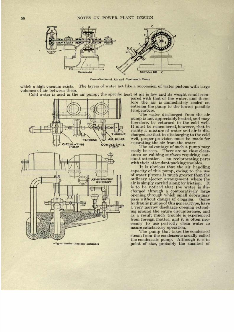
8/20/2019 notes on powerplant.pdf
http://slidepdf.com/reader/full/notes-on-powerplantpdf 62/202
56
NOTES
ON
POWER
PLANT
DESIGN
c
TURBINE
SECTION
AA
Cross-Section
of
Air
and
Condensate
Pump
which a
high
vacuum
exists.
The
layers
of water act
like a
succession
of
water
pistons
with
large
volumes
of
air
between
them.
Cold
water
is
used
in
the
air
pump;
the
specific
heat
of air
is low
and
its
weight
small
com-
pared
with
that
of
the
water,
and
there-
fore the
air
is
immediately
cooled
on
entering
the
pump
to
the
lowest
possible
temperature.
The
water
discharged
from
the
air
pump
is
not
appreciably
heated,
and
may
therefore,
be
returned
to
the
cold
well.
It
must
be
remembered,
however,
that
in
reality
a
mixture
of
water
and air is dis-
charged,
so that in
discharging
to
the
cold
well,
proper
provision
must be
made
for
separating
the
air from
the
water.
The
advantage
of such
a
pump may
easily
be
seen.
There
are
no close
clear-
ances
or
rubbing
surfaces
requiring
con-
stant attention
no
reciprocating
parts
with
their
attendant
packing
troubles.
It
is
obvious
that the
air
handling
capacity
of
this
pump,
owing
to
the
use
of
water
pistons,
is
much
greater
than the
ordinary
ejector
arrangement
where
the
ai
r
-
ls g}
m
piy
carried
along
by
friction.
It
is
to
be
noticed
that
the water is
dis-
charged
through
a
comparatively
large
opening
through
which small
debris
may
pass
without
clanger
of
clogging.
Some
hydraulic pumps
of
this
general
type,
have
a
very
narrow
discharge
opening
extend-
ing
around
the
entire
circumference,
and
as a
result
much
trouble
is
experienced
from
foreign
matter,
and
it
is
often nec-
essary
to use
perfectly
clean
water
co
insure
satisfactory
operation.
The
pump
that takes
the
condensed
steam
from
the
condenser
is
usually
called
the
condensate
pump.
Although
it is in
point
of
size, probably
the
smallest of
ypical
Surface
Condenser
Installation
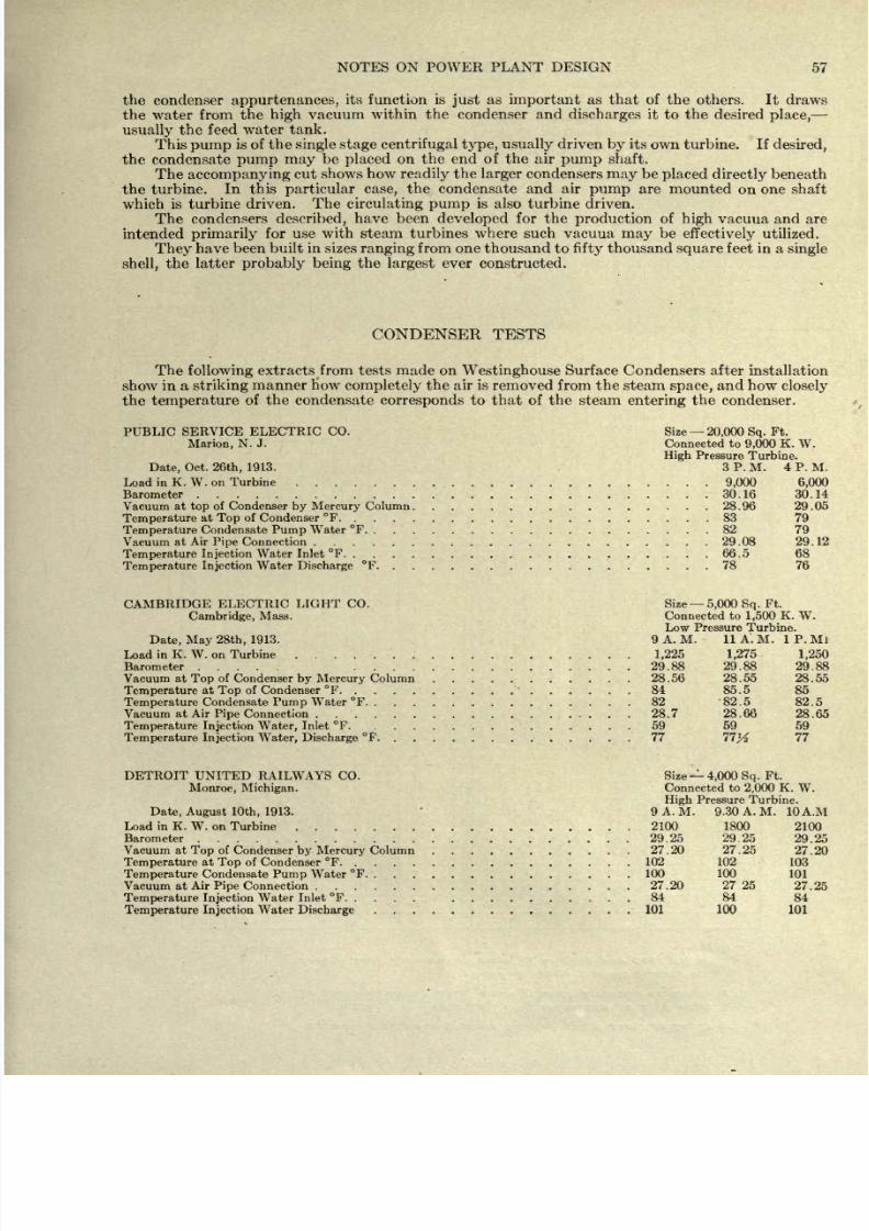
8/20/2019 notes on powerplant.pdf
http://slidepdf.com/reader/full/notes-on-powerplantpdf 63/202
NOTES ON
POWER
PLANT
DESIGN
57
the
condenser
appurtenances,
its function
is
just
as
important
as
that of the others.
It
draws
the water
from the
high
vacuum
within the
condenser
and
discharges
it
to
the
desired
place,
usually
the
feed water
tank.
This
pump
is of
the
single stage
centrifugal
type,
usually
driven
by
its
own turbine.
If
desired,
the condensate
pump
may
be
placed
on
the
end
of
the
air
pump
shaft.
The
accompanying
cut
shows how
readily
the
larger
condensers
may
be
placed
directly
beneath
the
turbine.
In
this
particular
case,
the
condensate
and air
pump
are
mounted
on
one shaft
which
is
turbine
driven.
The
circulating pump
is also turbine
driven.
The
condensers
described,
have been
developed
for the
production
of
high
vacuua
and are
intended
primarily
for
use
with steam
turbines
where such
vacuua
may
be
effectively
utilized.
They
have
been
built
in
sizes
ranging
from one thousand to
fifty
thousand
square
feet
in a
single
shell,
the
latter
probably
being
the
largest
ever
constructed.
CONDENSER
TESTS
The
following
extracts
from tests
made
on
Westinghouse
Surface
Condensers
after
installation
show
in
a
striking
manner
How
completely
the air is
removed
from
the
steam
space,
and
how
closely
the
temperature
of
the
condensate
corresponds
to
that of the
steam
entering
the condenser.
PUBLIC
SERVICE
ELECTRIC CO.
Size
20,000
Sq.
Ft.
Marion,
N. J.
Connected to
9,000
K.
W.
High
Pressure
Turbine.
Date,
Oct.
26th,
1913.
3
P.
M.
4
P. M.
Load
in
K.
W.
on Turbine
......................
9,000
6,000
Barometer
...........................
30.16 30.14
Vacuum
at
top
of Condenser
by
Mercury
Column
................
28.96
29.05
Temperature
at
Top
of
Condenser
F
....................
83
79
Temperature
Condensate
Pump
Water
F
...................
82
79
Vacuum
at
Air
Pipe
Connection
.....................
29.08
29.12
Temperature
Injection
Water Inlet
F
.............. ......
66.5 68
Temperature
Injection
Water
Discharge
F
..................
78
76
CAMBRIDGE
ELECTRIC
LIGHT CO. Size
5,000
Sq.
Ft.
Cambridge,
Mass.
Connected to
1,500
K.
W.
Low Pressure
Turbine.
Date,
May 28th,
1913.
9
A. M.
11 A.
M. 1 P. Ml
Load
in
K.
W.
on
Turbine .......
...........
1,225 1,275
1,250
Barometer .....
...............
29.88
29.88
29.88
Vacuum
at
Top
of
Condenser
by
Mercury
Column
...........
28.56
28.55
28.55
Temperature
at
Top
of
Condenser
F
..........
......
84 85.5 85
Temperature
Condensate
Pump
Water
F
...............
82
82.5
82.5
Vacuum
at
Air
Pipe
Connection
..................
28.7
28.66
28.65
Temperature Injection
Water,
Inlet
F
...............
59
59
59
Temperature
Injection Water,
Discharge
F
..............
77
11%
11
DETROIT
UNITED
RAILWAYS
CO. Size
4,000
Sq.
Ft.
Monroe, Michigan.
Connected to
2,000
K.
W.
High
Pressure
Turbine.
Date,
August
10th,
1913.
9A.M.
9.30A.M. 10A.M
Load in
K.
W. on
Turbine
..................
2100 1800
2100
Barometer
.......................
29.25 29.25
29.25
Vacuum
at
Top
of
Condenser
by
Mercury
Column
...........
27.20
27.25
27.20
Temperature
at
Top
of
Condenser
F
................
102 102
103
Temperature
Condensate
Pump
Water
F
...............
100 100
101
Vacuum at
Air
Pipe
Connection
.................
27.20 2725
27.25
Temperature
Injection
Water Inlet
F
..... ..........
84 84
84
Temperature
Injection
Water
Discharge
..............
101
100 101
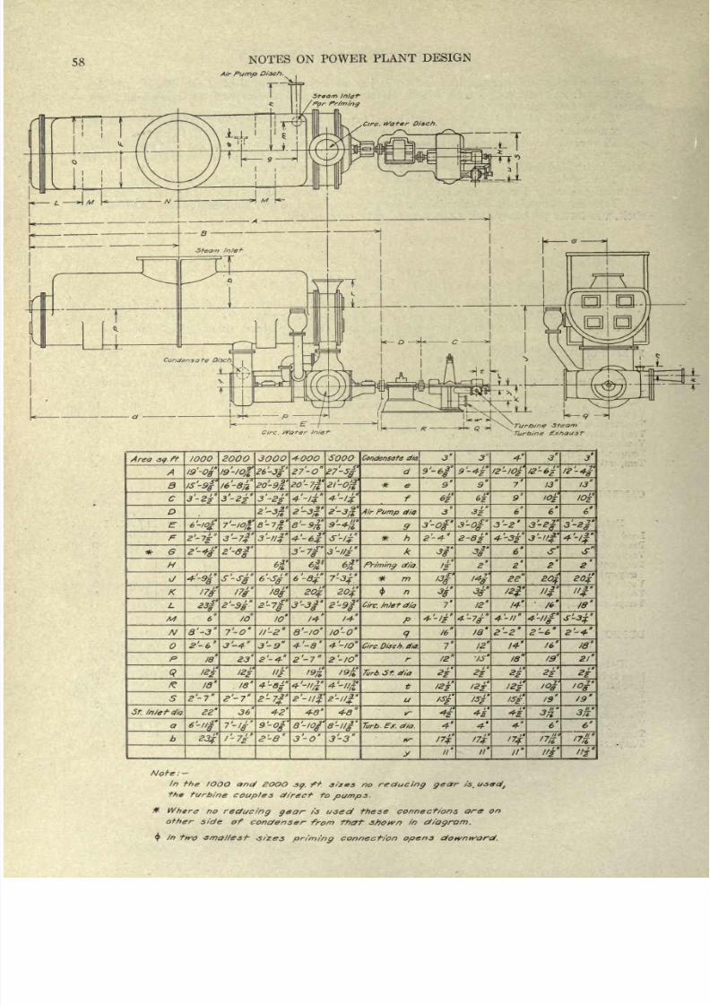
8/20/2019 notes on powerplant.pdf
http://slidepdf.com/reader/full/notes-on-powerplantpdf 64/202
58
NOTES
ON
POWER
PLANT
DESIGN
Air
Pump
Di-sch.
r
EZIt
Circ.
Wafer
In/ei-
Turbine
Steam
Turbine
Exhaust
Area
s<?
ft.
/OOO
2OOO 3OOO
4-OOO
SOOO
Condensatc dip
*
G
H
M
Mef cfio.
IS'
-O
19
-/
-J--
/s-s
6-/0/
8'~3
2'-
6
te
18
6'-i'
S'-S
/O
7'-o
is
36
26'-3
ft
7
*
8
7
/6
10
3-9
2'
-4-
4--SJ
B-7
4-2
9-$'
2-ff
27-O
8-9%
6
-8
Q'-IO
4-'-8
2
'-
7
4-8'
j-o
3-
1/?
20*
14-
/o'-o*
'-to
2 '-10
4-8
ff '-//
3'-3
*
e
Air
Pump
dia
*
h
Priming
of/a.
C/rc.
Inlet
dia
C/rc.
Disch.
dio.
Turb.
St.
efia
Turb
Ex.
d/a.
y
9'-6J
2-4-
16
7'
4-'
3s
3-0
2-8
12
4-7*
IB
12
ta
4k
12-
I
3-2
6'
28
2-2
14-'
/a
2
13
3-
11$
20
/*
2-6
13
IDs
+-'
20
4
18
18
2?
>*
Noi-e:-
lr>
the
IOOO
etna/
SOOO
sp.
f+. s/zrs
no
reducing
year
is.
u-secj,
the
turbine
couples
direct
to
pumpj.
*
Where no
reducing
gear-
i-s
used
these
connections
are
on
of
her
side
of
condenser
from that
shown
in
diagram.
$
In
two
-smallest
-sizes
priming
connect/on
opens
downward.
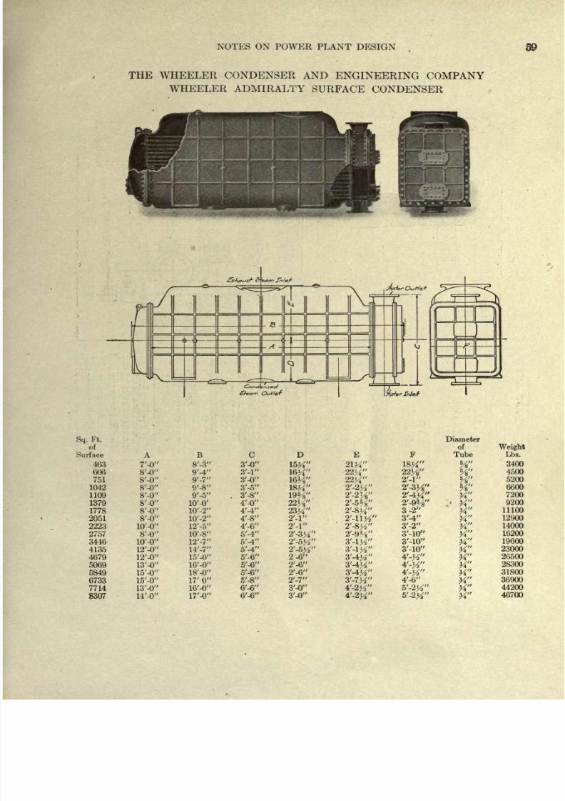
8/20/2019 notes on powerplant.pdf
http://slidepdf.com/reader/full/notes-on-powerplantpdf 65/202
NOTES
ON
POWER
PLANT
DESIGN
THE WHEELER
CONDENSER
AND
ENGINEERING
COMPANY
WHEELER ADMIRALTY
SURFACE
CONDENSER
Sq.
Ft.
of
Surface
463
606
751
1042
1109
1379
1778
2051
2223
2757
3446
4135
4679
5069
5849
6733
7714
8307
A
7'-0
8'-0
8'-0
8'-0
8'-0
8'-0
8'-0
8'-0
lO'-O
8'-0
lO'-O
B
8'-3
9'-4
9'-7
9'-8
9'-5
10'
-8
17'
0
c
3'-0
3'-0
3'-5
3'-8
4'-0
4'-4
4'-8
4'-6
5'-4
5'-4
5'-4
5'-6
5'-6
5'-6
5'-8
6'-6
D
E
21K
22^
22y
23^
2-6
2'-6
2'-6
2'-7
3'-0
3'-0
22H
2'-l
2'W
3-2
3'-4
3'-2
Diameter
of
Tube
K
W
*A
5
K
K
Weight
Lbs.
3400
4500
5200
6600
7200
9200
11100
12900
14000
16200
19600
23000
26500
28300
31800
36900
44200
46700
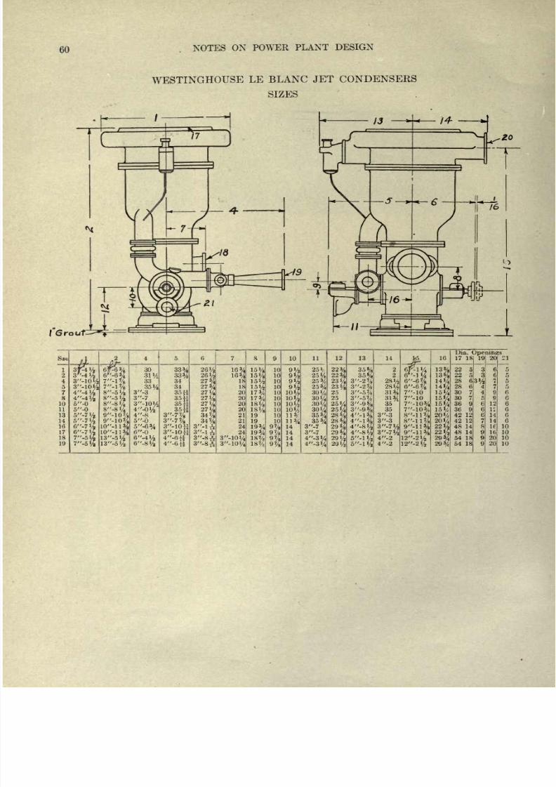
8/20/2019 notes on powerplant.pdf
http://slidepdf.com/reader/full/notes-on-powerplantpdf 66/202
60
NOTES
ON
POWER
PLANT
DESIGN
WESTINGHOUSE
LE
BLANC
JET
CONDENSERS
SIZES
I
Grou
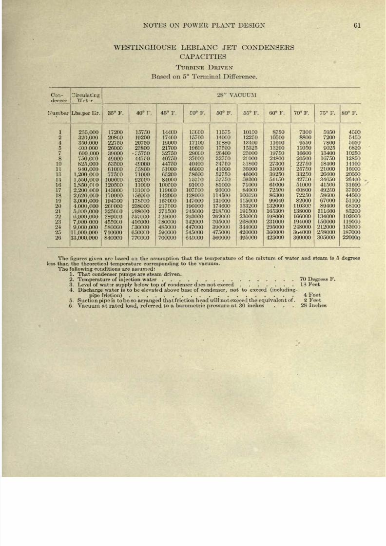
8/20/2019 notes on powerplant.pdf
http://slidepdf.com/reader/full/notes-on-powerplantpdf 67/202
NOTES ON POWER
PLANT
DESIGN
61
WESTINGHOUSE
LEBLANC
JET CONDENSERS
CAPACITIES
TURBINE
DRIVEN
Based
on
5
Terminal
Difference.
Con-
denser
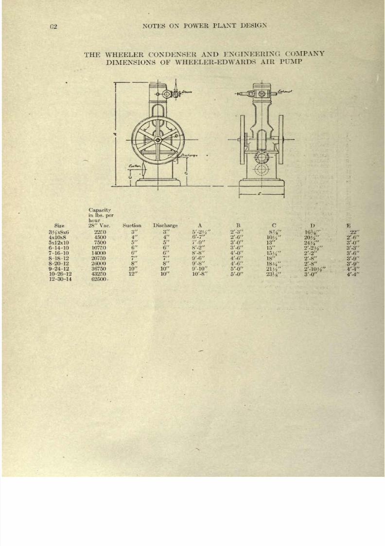
8/20/2019 notes on powerplant.pdf
http://slidepdf.com/reader/full/notes-on-powerplantpdf 68/202
C2
NOTES
ON POWER
PLANT
DESIGN
THE WHEELER
CONDENSER
AND
ENGINEERING
COMPANY
DIMENSIONS
OF
WHEELER-EDWARDS
AIR
PUMP
4x10x8
5x12x10
6-14-10
7-16-10
8-18-12
8-20-12
9-24-12
10-26-12
12-30-14
Capacity
in Ibs.
per
hour
28
Vac.
4500
7500
10750
14000
20750
26000
36750
43250
62500-
Suction
3
4
5
6
6
7
8
10
12
Discharge
3
4
5
6
6
7
8
10
10
6'-7'
V-9'
8'-2'
8'-8'
9'-6'
9'-8'
B
2'-3
2'-6
3'-0
3'-6
4'-0
4'-6
4'-6
5'-0
5'-0
10K
13
15
D
W
18
1834
2ly
2434
2'-2#
2'-2
2'-8
2'-S
3'-0
E
22
2'-6
3'-0
3'-3
3'-6
3'-9
3'-9
4'-4
4'-4
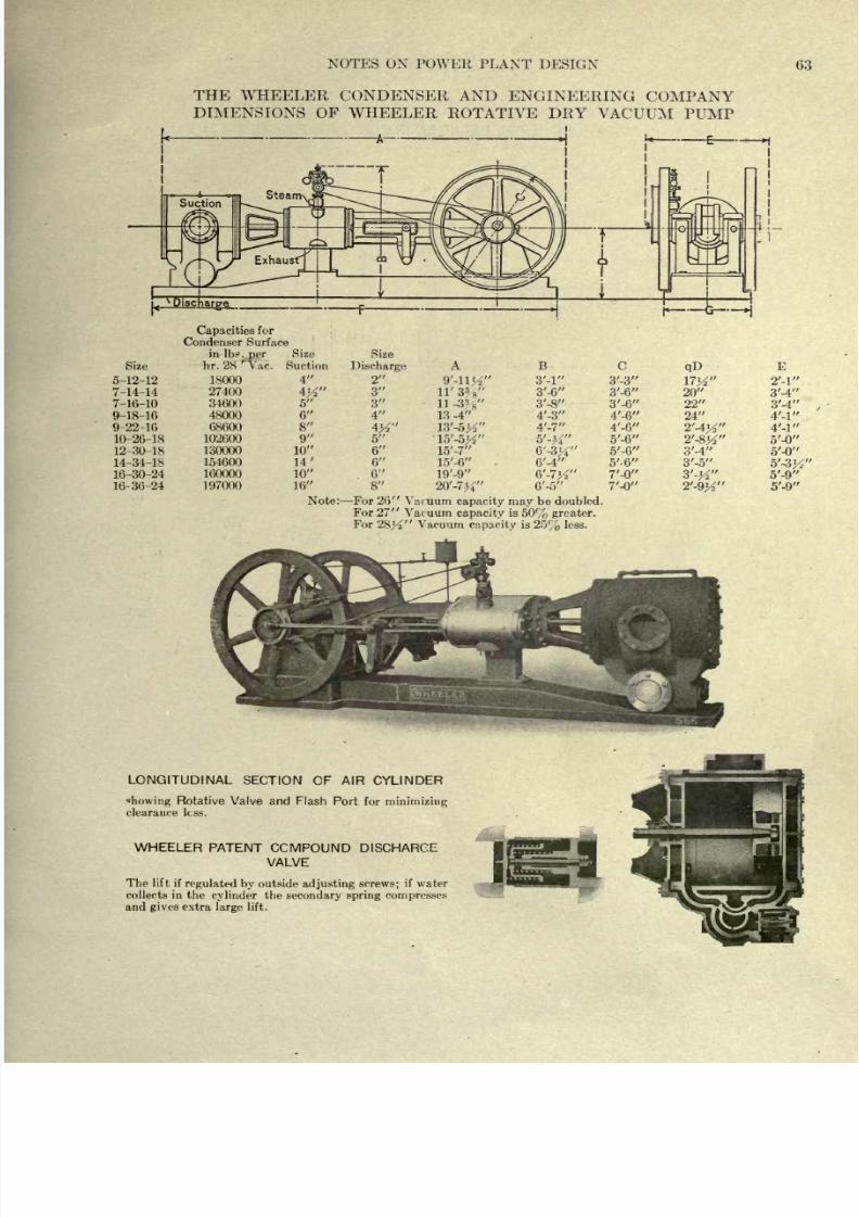
8/20/2019 notes on powerplant.pdf
http://slidepdf.com/reader/full/notes-on-powerplantpdf 69/202
NOTES
ON POWER
PLANT
DESIGN
63
THE
WHEELER
CONDENSER AND
ENGINEERING
COMPANY
DIMENSIONS
OF WHEELER
ROTATIVE
DRY VACUUM
PUMP
Size
5-12-12
7-14-14
7-16-10
9-18-16
9-22-16
10-26-18
12-30-18
14-34-18
16-30-24
16-36-24
Capacities
for
Condenser Surface
in
Ibs.
per
Size
hr. 28
'
Vac. Suction
18000
27400
34600
48000
08600
102600
130000
154600
160000
197000
4
5
2
6
8
9
10
14'
10
16
Note
Size
Discharge
2
3
3
4
W
5
6
6
6
8
11'32-s
11
-W
13-4
B
3'-l
3'-6
3'-8
4'-3
4'-7
6'-4
6'-7^
6'-5
C
3'-3
3'-6
3'-6
4'-6
4'-6
5'-6
5'-6
5'-6
7'-0
7'-0
qD
20
22
24
3'-4
3'-5
3'-4
3'-4
5'-0
5'-0
5'-3
5'-9
5'-9
:
For
26
Vacuum
capacity
may
be
doubled.
For
27
Vacuum
capacity
is
50% greater.
For
28^
Vacuum
capacity
is
25%
less.
LONGITUDINAL
SECTION
OF
AIR
CYLINDER
howing
Rotative Valve and
Flash
Port for
minimizing
clearance
less.
WHEELER
PATENT
CCMPOUND
DISCHARGE
VALVE
The
lift
if
regulated
by
outside
adjusting
screws;
if water
collects
in
the
cylinder
the
secondary spring
compresses
and
gives
extra
large
lift.
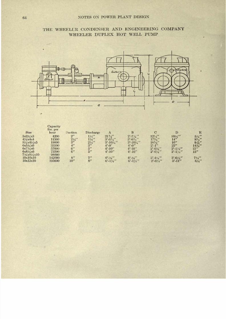
8/20/2019 notes on powerplant.pdf
http://slidepdf.com/reader/full/notes-on-powerplantpdf 70/202
64
NOTES
ON
POWER
PLANT
DESIGN
THE
WHEELER
CONDENSER
AND
ENGINEERING
COMPANY
WHEELER
DUPLEX
HOT WELL
PUMP
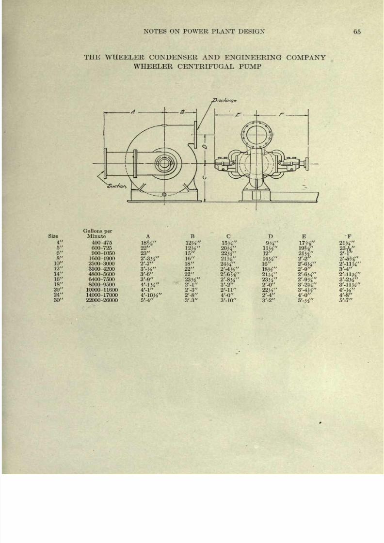
8/20/2019 notes on powerplant.pdf
http://slidepdf.com/reader/full/notes-on-powerplantpdf 71/202
NOTES
ON
POWER
PLANT
DESIGN
65
THE WHEELER
CONDENSER
AND
ENGINEERING COMPANY
WHEELER CENTRIFUGAL
PUMP
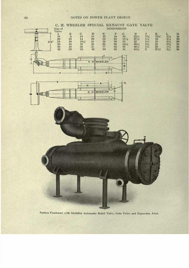
8/20/2019 notes on powerplant.pdf
http://slidepdf.com/reader/full/notes-on-powerplantpdf 72/202
66
NOTES
ON
POWER
PLANT
DESIGN
C.
H.
WHEELER
SPECIAL
EXHAUST GATE VALVE
DIMENSIONS
H
K
32
16
16
21
25
M
16
20
20
24
36
36
Surface
Condenser
with
Multiflex
Automatic
Relief
Valve,
Gate
Valve
and
Expansion
Joint.
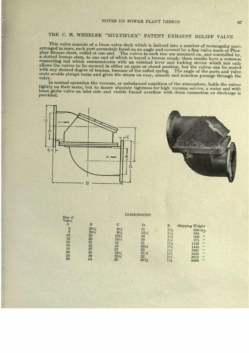
8/20/2019 notes on powerplant.pdf
http://slidepdf.com/reader/full/notes-on-powerplantpdf 73/202
NOTES
ON
POWER
PLANT
DESIGN
67
THE
C.
H.
WHEELER
MULTIPLEX
PATENT
EXHAUST
RELIEF
VALVE
This
valve
consists
of
a
brass
valve
deck
which
is
ihdived
into
a
number
of
rectangular ports
anged
in
rows,
each
port
accurately
faced
on an
angle
and
covered
by
a
flap
valve
made
of
Phos-
jnor
Bronze
sheet,
coiled
at
one
end.
The
valves in
each
row
are
mounted
on,
and
controlled
by
tted
bronze
stem,
to
one
end of
which
is
keyed
a
bronze
crank;
these
cranks
have
a
common
ctmg
rod
which
communicates
with
an
external
lever
and
locking
device
which
not
onlv
allows
the
valves
to
be
secured in
either an
open
or
closed
position,
but
the
valves
can
be
seated
with
any
desired
degree
of
tension,
because
of the
coiled
spring.
The
angle
of
the
ports
and
valve
ds
abrupt
turns
and
gives
the
steam
an
easy,
smooth
and
noiseless
passage
through
the
+
^
non
?
a
P
eration
the
vacuum,
or
unbalanced
condition
of
the
atmosphere,
holds
the
valve*
tightly
on
their
seats;
but to
insure
absolute
tightness
for
high
vacuum
service,
a
water
seal
with
brass
globe
valve
on
inlet
side
and
visible
funnel
overflow
with
drain
connection on
discharge
is
provided.
Size
of
Valve
A
6
8
10
12
14
16
18
20
24
30
B
28^
DIMENSIONS
D
11
29
29
37
42
37
45
56
64
12
13
21
26
16
19
21
23^
25
27K
32
38%
Shipping
Weight
330
Ibs
384
900
975
1128
1440
1995
2440
3822
6000
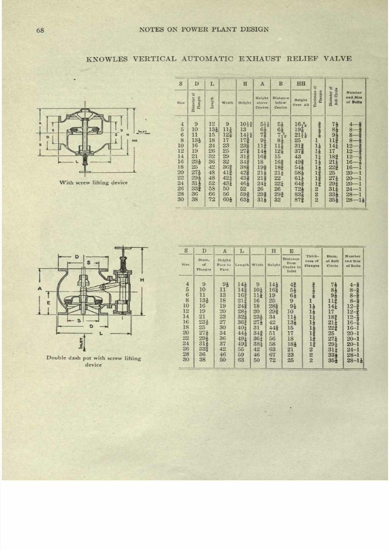
8/20/2019 notes on powerplant.pdf
http://slidepdf.com/reader/full/notes-on-powerplantpdf 74/202
68
NOTES
ON
POWER
PLANT
DESIGN
KNOWLES
VERTICAL AUTOMATIC
EXHAUST
RELIEF
VALVE
With
screw
lifting
device
s
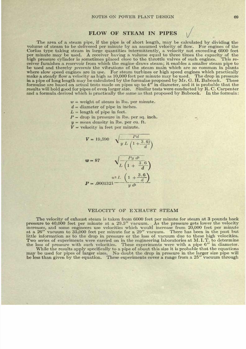
8/20/2019 notes on powerplant.pdf
http://slidepdf.com/reader/full/notes-on-powerplantpdf 75/202
NOTES ON
POWER
PLANT
DESIGN
FLOW OF
STEAM
IN
PIPES
The
area
of
a
steam
pipe,
if
the
pipe
is of
short
length,
may
be
calculated
by dividing
the
volume
of
steam
to
be
delivered
per
minute
by
an
assumed
velocity
of flow.
For
engines
of the
Corliss
type
taking
steam
in
large
quantities
intermittently,
a
velocity
not
exceeding
6000
feet
per
minute
may
be
used.
A
receiver
having
a
volume
equal
to
three
times the
capacity
of
the
high
pressure
cylinder
is sometimes
placed
close
to
the throttle
valves
of
such
engines.
This
re-
ceiver
furnishes
a
reservoir from
which
the
engine
draws steam
;
it
enables
a smaller
steam
pipe
to
be
used
and
thereby
prevents
the
vibrations
of
the steam main
which
are
so
common
in
plants
where
slow
speed engines
are in use.
For
steam turbines or
high
speed engines
which
practically
make a
steady
flow
a
velocity
as
high
as
10,000
feet
per
minute
may
be
used.
The
drop
in
pressure
in
a
pipe
of
long length may
be calculated
by
the
formulae
proposed
by
Mr.
G. H. Babcock.
These
formulae are based
on actual tests
made
on
pipes up
to 4
in
diameter,
and it is
probable
that the
results
will
hold
good
for
pipes
of
even
larger
size.
Similar
tests
were conducted
by
R.
C.
Carpenter
and
a formula
derived
which
is
practically
the
same
as
that
proposed
by
Babcock.
In
the
formula
:
w
=
weight
of
steam
in
Ibs.
per
minute.
d
=
diameter
of
pipe
in
inches.
L
=
length
of
pipe
in
feet.
P
=
drop
in
pressure
in
Ibs.
per sq.
inch.
y
=
mean
density
in
Ibs.
per
cu.
ft.
V
=
velocity
in
feet
per
minute.
V
=
19,590
'
Pd
P=
.0001321
-*--*
~
VELOCITY
OF
EXHAUST
STEAM
The
velocity
of
exhaust steam
is
taken from
6000 feet
per
minute for steam
at 3
pounds
back
pressure
to
40,000
feet
per
minute
at a
29.5
vacuum.
As the
pressure
gets
lower
the
velocity
increases,
and
some
engineers
use
velocities which
would
increase
from
20,000
feet
per
minute
at
a
26
vacuum
to
35,000
feet
per
minute
for
a
29 vacuum. There
has been
in
the
past
but
little information as to
the
drop
in
pressure
or
the
loss
of vacuum due to these
high
velocities.
Two
series
of
experiments
were
carried
on
in
the
engineering
laboratories
at
M.I.T.
to
determine
the
loss of
pressure
with
such
velocities. These
experiments
were
with
a
pipe
6
in diameter.
While the
results
apply
specifically
to
a
pipe
of about
this
size it
is
probable
that
the
equations
may
be used
for
pipes
of
larger
sizes.
No
doubt
the
drop
in
pressure
in the
larger
size
pipe
will
be
less
than
given
by
the
equation.
These
experiments
cover
a
range
from
a 25
vacuum
through
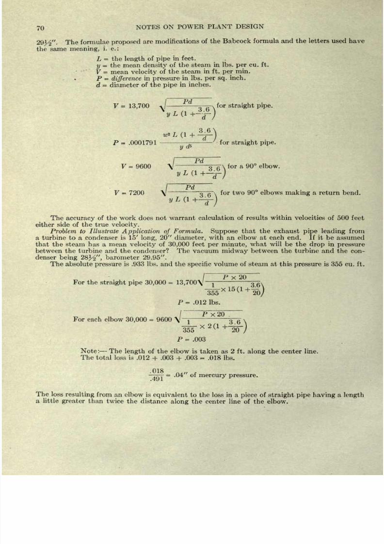
8/20/2019 notes on powerplant.pdf
http://slidepdf.com/reader/full/notes-on-powerplantpdf 76/202
70
NOTES
ON
POWER
PLANT
DESIGN
29^ .
The
formulae
proposed
are
modifications
of
the
Babcock
formula and the letters used
have
the
same
meaning,
i. e.:
L
=
the
length
of
pipe
in feet.
y
=
the
mean
density
of
the steam
in
Ibs.
per
cu.
ft.
V
=
mean
velocity
of
the
steam
in ft.
per
min.
P
=
difference
in
pressure
in
Ibs.
per
sq.
inch.
d
=
diameter
of the
pipe
in
inches.
V
=
13,700
o
a\
for
straight
pipe.
P
=
.0001791
-
-T-
/
for
straight pipe.
y
5
/
Pd
V
= 9600
\
-
o
ft \
for
a 90
elbow.
V
=
7200
\/
--
<T~A~\
for
two
90
elbows
making
a
return
bend.
'
The
accuracy
of
the
work
does
not
warrant
calculation
of
results
within
velocities of 500
feet
either
side
of
the
true
velocity.
Problem to
Illustrate
Application
of
Formula.
Suppose
that the exhaust
pipe
leading
from
a
turbine to
a condenser
is 15'
long,
20
diameter,
with
an
elbow at
each
end. If
it
be assumed
that
the
steam
has a
mean
velocity
of
30,000
feet
per
minute,
what
will
be the
drop
in
pressure
between the turbine and the
condenser?
The
vacuum
midway
between
the
turbine
and
the
con-
denser
being
28% ,
barometer
29.95 .
The
absolute
pressure
is
.933
Ibs. and the
specific
volume
of steam
at this
pressure
is
355 cu.
ft.
P
X
20
For
the
straight
pipe
30,000
=
13,700\'
1
i*/,
3.6\
T55
xl5(1+
To)
P
=
.012 Ibs.
/
P
X
20 .
For
each
elbow
30,000
=
9600
\
-j
3-
355
20
P
=
.003
Note: The
length
of
the elbow is
taken
as
2
ft.
along
the
center
line.
The
total
loss is
.012
+
.003
+
.003
=
.018
Ibs.
.018
-T^T
=
.04 of
mercury
pressure.
The
loss
resulting
from
an
elbow is
equivalent
to the loss
in a
piece
of
straight
pipe having
a
length
a
little
greater
than
twice
the
distance
along
the
center line
of
the
elbow.
8/20/2019 notes on powerplant.pdf
http://slidepdf.com/reader/full/notes-on-powerplantpdf 77/202
NOTES
ON
POWER
PLANT
DESIGN
71
Example
to
Illustrate
An
engine
is
connected
to
a barometric
tube
condenser
through
40
feet
of vertical
pipe,
10
feet
of
horizontal
pipe
and three
elbows;
one
elbow
being
located at the
exhaust
opening
of
the
cylinder
and the
second
and
third
elbows
being
on
the vertical
pipe leading
to
the
condenser.
The
exhaust
pipe
is
12 diameter
and
the
vacuum
to
be
maintained
is
26 ,
with the
barometer
at
30.1 .
If the
maximum difference
in
pressure
between the condenser and
the
engine
is
to be
not
over
.1 of
Hg.
how
many
pounds
of
steam
per hour can be put through
this
12
pipe?
The
length
through
the center
of
a
12
elbow is
about
1
foot
so that
about
1x2x3=6
feet
should
be
added
to the
length
of
the
pipe
making
a total of
56
feet.
.0491
x
12
F
=
13,700 \
j-
~T1T\
v
=
16,150
ft.
per
min.
172
X
56
16150
x
.7854
x
60
172
Had
.2
mercury
been
the
greatest
drop
allowed
.2
x
.491
x
12
x
172
F
=
13,700
\
o
fi
\
F
=
22,850
and
10,400
Ibs. could
be taken care
of
through
the 12
pipe.
8/20/2019 notes on powerplant.pdf
http://slidepdf.com/reader/full/notes-on-powerplantpdf 78/202
72
NOTES
ON POWER
PLANT
DESIGN
FEED WATER
HEATERS
Feed
water
heaters are of
two
classes, open
heaters
and closed heaters.
In an
open
heater
the
water
can
not
be
heated
above
212
while in
a
closed
heater
higher
temperatures
than
212
are
possible.
A
primary
heater
is a
heater
placed
on
the
exhaust
pipe
between the
main
engine
or turbine
and
the condenser.
A
secondary
heater
which
may
be either
an
open
or
a
closed
heater
utilizes the
heat of the
auxiliaries,
exhausting
at
atmospheric
pressure,
in
raising
the
temperature
of
the
water
leaving
the
primary
heater
to
a
temperature
within
8
or
10
degrees
of that
of
the
exhaust
steam.
From the
secondary
heater
the
water
passes
through
the economizer
(if
one is
used)
to the boiler.
A feed
water
heater is
very
much like
a
surface
condenser
and
consequently
the same
laws,
regarding
the
interchange
of
heat
per
square
foot of
surface
per
degree
difference
of
temperature,
apply.
The
interchange
of heat
in
condensers
was
found to
be
proportional
to
the
square
root of
the
velocity
of
the
water
through
the
tubes. Feed
water
heaters
designed
for
torpedo boats, etc.,
where
space
is
very
limited
have
been
made
with
the
water
flowing
at
high
velocity
in
the
annular
space
between two
tubes
placed
one
inside
the
other.
The
high
velocity
of
water
gives
a
large
interchange
of
heat but
requires
8
or
10
Ibs.
additional
pressure
on
the
pump
forcing
the water
through
the
heater.
The C. H.
Wheeler Co.
use
the
following
formula
in
figuring
the surface needed
in
a closed
heater:
S
=
sq.
ft.
surface
W
=
Ibs.
of
water
per
hour
t
a
=
temperature
of
steam
F.
t
c
=
temperature
of
cold
water
entering
F.
th
=
temperature
of
hot
water
leaving
F.
K
-
constant
of
transmission
taken
as
250
-
W
2.3026
log
w
^r
It
is
always
safer to
put
in
a
larger
heater
than
appears
at first
to
be
necessary.
Tables of
dimensions
of
both a
Primary
and
a
Secondary
heater are
given.
These
tables
will
give
the
general
dimensions
only.
The
feed
piping
at
a
heater
should
be
arranged
so
that in case
of
any
trouble with
the
heater,
the
water can
be
by-passed
around
the
heater.
This
necessitates
three valves. The
piping
must
be
of
brass
in
order
to
resist the
action
of
the hot
water.
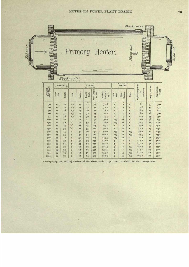
8/20/2019 notes on powerplant.pdf
http://slidepdf.com/reader/full/notes-on-powerplantpdf 79/202
NOTES
ON
POWER
PLANT
DESIGN
73
Primary
Heater.
1
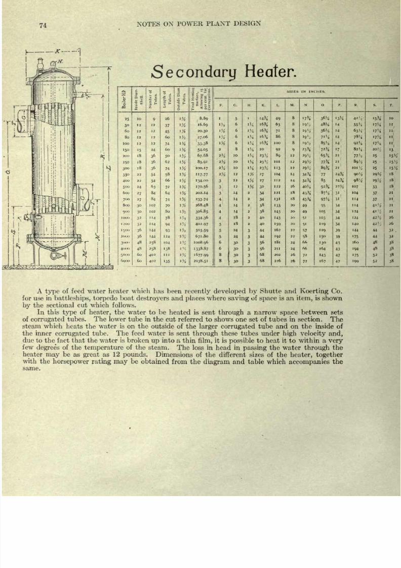
8/20/2019 notes on powerplant.pdf
http://slidepdf.com/reader/full/notes-on-powerplantpdf 80/202
74
NOTES
ON
POWER
PLANT
DESIGN
Secondary
Heater.
a.
L,
6
03
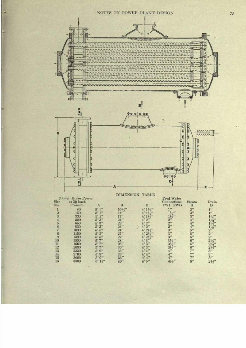
8/20/2019 notes on powerplant.pdf
http://slidepdf.com/reader/full/notes-on-powerplantpdf 81/202
NOTES ON
POWER
PLANT
DESIGN
75
DIMENSION TABLE
(Boiler
8/20/2019 notes on powerplant.pdf
http://slidepdf.com/reader/full/notes-on-powerplantpdf 82/202
8/20/2019 notes on powerplant.pdf
http://slidepdf.com/reader/full/notes-on-powerplantpdf 83/202
NOTES
ON
POWER
PLANT
DESIGN
77
In
making
a calculation for a
tower it
is
probably
safe
to
assume
a
difference of
15
degrees.
The
air
leaving
the tower
may
be saturated or
only partially
saturated,
the
condition
depending
upon
the amount
of
air
sent in and the
design
of the tower.
In
general
it is a
good plan
to
assume
that
the
air
at
the
top
of
the
tower
is
only
90%
saturated
and
that
the
temperature
of this
air
is
15
degrees
lower than the
temperature
of
the hot water
entering
the
tower.
These
assumptions
have been
made
in the
calculations
which
follow.
E
=
.90
x
Vh
Y
h
-
relative
humidity
x
V
c
Y
e
In
the
case
of
a
jet
condenser
the
steam
condensed
adds
one
pound
to each Z
pounds
of
cooling
water
entering
the
condenser.
If
E is
greater
than one
pound
then
the
excess must be
supplied
as
make-up
water.
For
a
surface
condenser
E
represents
the
make-up
water.
Problem.
A
cooling
tower
receives water from a
surface
condenser
at
122
F.,
the
water leaves the
cooling
tower
at
90
F.; temperature
of
outside
air
72,
relative
humidity
80%.
Temperature
of
condensed steam
95,
vacuum in condenser
25 ,
barometer
29.7 .
Engine
of
500
H. P.
and
consumes
20
pounds
of steam
per
H.
P.
What
is
the amount
of
air needed
per
pound
of
steam
condensed
and
what is the
per
cent
loss
of
cooling
water
due
to
evaporation?
1053.2
-
63.1
__990.J_
90.0
-
58.1
=
31.9
V
c
x
566.5
x
.00347
,,, 79
t
=
.754
x
531.5
X
>24
531.5
29.7
|
l
-
.8
V
c
x
.00124
[
The
figures
.00347 and .00124 are the
Ibs.
of
water
required
to
saturate
a
cu.
ft.
of
dry
air
at
107 and
at 72
deg.
respectively.
The
figure
1031.8
is.
the value of the
heat
of
vaporization
at
107.
990.1
=
3.036
V
c
V
c
=
326 cu. ft.
E
=
(.00333
-
.00099)
V
c
=
.763 Ibs.
evaporation
per
Ib.
of steam condensed
or
per
31.8
Ibs.
of
circulating
water.
This
is
^r -5-
=
.0240
or
2.40%
shrinkage.
As
the
first term of the
right
hand
side of
this
equation
ol
. o
623
evaluates .623
F
c
it
is
evident that
the
heat
carried off
by
the
air
is
55^
percentage
of the total
o
.
amount
abstracted.
This
figures
as
20.5%;
the heat taken out
by
evaporation
being 79.5%.
To illustrate more
fully
the
use
of
the
equation
and to illustrate also
the
extra
cost
(at
the
cooling
tower)
of
a
high
vacuum
over a
moderate
vacuum, two
cases
will
be
taken
up
:
First
a
condensing
and
cooling
outfit
maintaining
a 28
vacuum
and, second,
a
similar
outfit
maintaining
a
26
vacuum.
The
illustration
will
be worked
through
-for each
case
with
relative
humidities of
the
enter-
ing
air
as
90,
as
70,
and
as
50%
First
case A condenser
maintaining
a
28
vacuum
with hot
condensing
water at
95
or
7
degrees
below the
temperature corresponding
to
the
vacuum.
The exhaust steam
is
assumed
to
contain
4%
of moisture.
The
temperature
of the
air
may
be taken
as
72 and
it will
be
assumed
that
the tower
is
to
cool
the
water to
this
temperature.
For
air
90%
saturated
at
72
the volume
required
per pound
of steam
=
V
c
may
be cal-
culated
thus:
To abstract the heat from
a
pound
of
exhaust steam
43.5
Ibs.
of
cooling
water
would
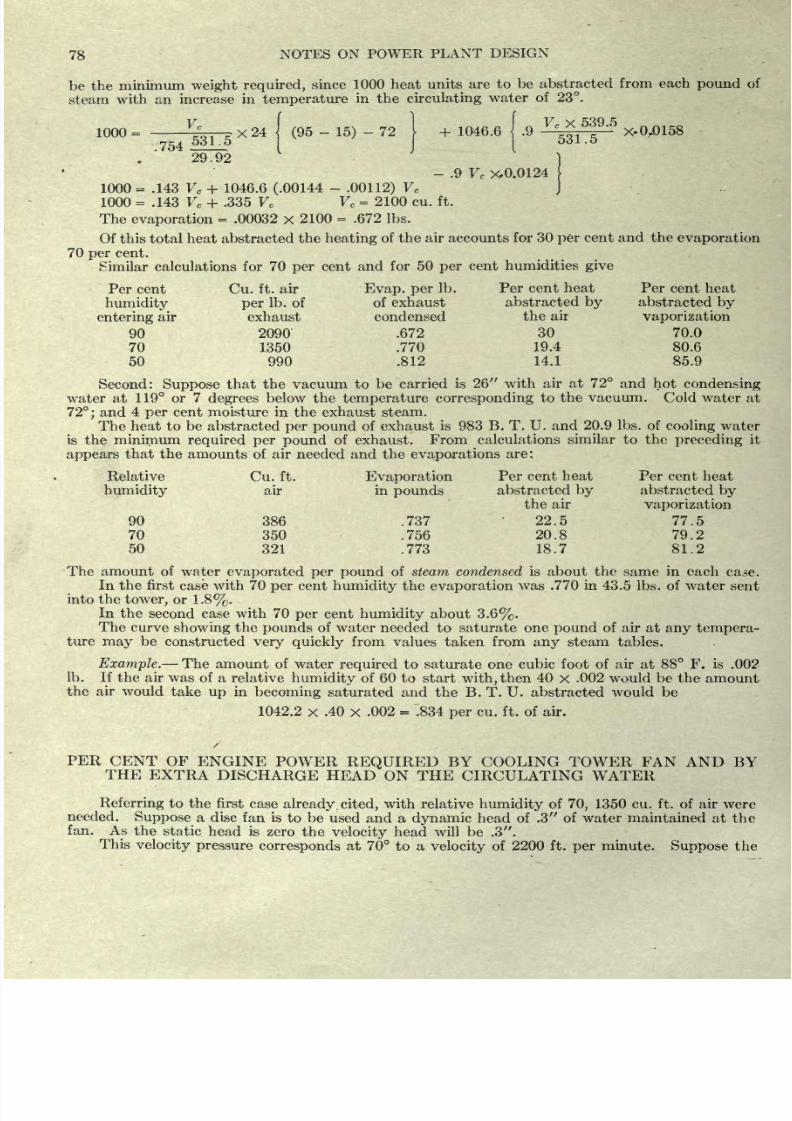
8/20/2019 notes on powerplant.pdf
http://slidepdf.com/reader/full/notes-on-powerplantpdf 84/202
78
NOTES
ON
POWER
PLANT DESIGN
be the
minimum
weight required,
since
1000
heat
units
are to
be
abstracted
from
each
pound
of
steam
with an
increase
in
temperature
in the
circulating
water
of
23.
V v
1000
=
J^rj-r
X
24
{
(95
-
15)
-
72
[
+
1046.6
\
.9
Ve
*-
X-0,0158
754
5ol
5
.
'
29.92
)
-
.9
V
c
x.0.0124
1000
=
.143 V
c
+
1046.6
(.00144
-
.00112)
V
c
1000
=
.143
V
c
+
.335
V
c
V
c
=
2100
cu. ft.
The
evaporation
=
.00032
x
2100
=
.672
Ibs.
Of
this
total
heat
abstracted
the
heating
of the
air accounts
for
30
per
cent and the
evaporation
70
per
cent.
Similar calculations for
70
per
cent and
for
50
per
cent humidities
give
Percent Cu.
ft. air
Evap. per
Ib. Per cent
heat
Per
cent heat
humidity
per
Ib.
of of
exhaust abstracted
by
abstracted
by
entering
air
exhaust
condensed
the
air
vaporization
90
2090
.672
30 70.0
70
1350
.770
19.4
80.6
50 990
.812
14.1
85.9
Second:
Suppose
that
the vacuum to be
carried is
26 with
air
at
72 and
hot
condensing
water at
119 or 7
degrees
below the
temperature
corresponding
to
the
vacuum.
Cold water
at
72;
and
4
per
cent moisture
in
the
exhaust
steam.
The
heat to
be
abstracted
per
pound
of
exhaust is 983
B.
T. U.
and 20.9 Ibs. of
cooling
water
is the minimum
required
per
pound
of
exhaust. From
calculations
similar to the
preceding
it
appears
that the
amounts
of
air
needed and the
evaporations
are:
Relative
Cu. ft.
Evaporation
Per
cent
heat
Per cent
heat
humidity
air
in
pounds
abstracted
by
abstracted
by
the
air
vaporization
90
386
.737
22.5 77.5
70
350
.756
20.8
79.2
50
321
.773
18.7 81.2
The
amount
of
water
evaporated
per pound
of
steam condensed is about the
same
in each
ca.se.
In
the
first
case
with 70
per
cent
humidity
the
evaporation
was
.770
in
43.5 Ibs.
of
water
sent
into
the
tower,
or
1.8%.
In the
second
case with 70
per
cent
humidity
about
3.6%.
The
curve
showing
the
pounds
of water
needed
to
saturate
one
pound
of air
at
any tempera-
ture
may
be
constructed
very
quickly
from
values taken from
any
steam
tables.
Example.
The
amount
of
water
required
to saturate
one
cubic
foot
of air
at
88
F.
is .002
Ib.
If
the
air
was
of
a
relative
humidity
of
60
to
start
with,
then
40
x
.002
would
be
the
amount
the
air
would
take
up
in
becoming
saturated
and
the
B. T.
U.
abstracted would
be
1042.2
x
.40
x
.002
=
.834
per
cu.
ft.
of air.
PER
CENT
OF
ENGINE
POWER
REQUIRED
BY
COOLING
TOWER
FAN AND BY
THE
EXTRA
DISCHARGE HEAD
ON
THE
CIRCULATING
WATER
Referring
to
the
first
case
already
cited,
with relative
humidity
of
70,
1350
cu.
ft. of air
were
needed.
Suppose
a
disc
fan
is
to be used
and a
dynamic
head
of .3 of water maintained at the
fan.
As
the
static
head is
zero the
velocity
head
will be .3 .
This
velocity
pressure
corresponds
at
70
to
a
velocity
of
2200
ft.
per
minute.
Suppose
the
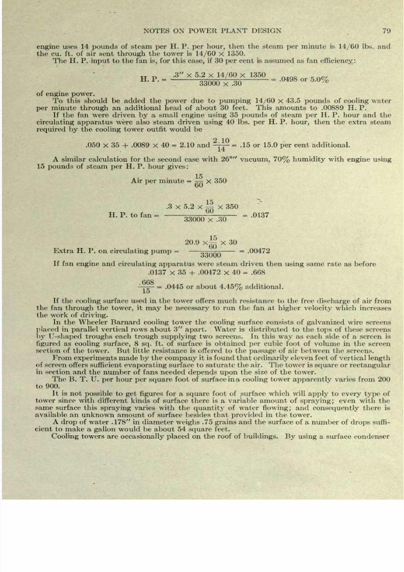
8/20/2019 notes on powerplant.pdf
http://slidepdf.com/reader/full/notes-on-powerplantpdf 85/202
NOTES
ON POWER
PLANT
DESIGN
.
79
engine
uses 14
pounds
of
steam
per
H.
P.
per
hour,
then
the steam
per
minute
is
14/60
Ibs.
and
the cu.
ft.
of
air
sent
through
the
tower
is
14/60
x
1350.
The
H. P.
input
to the
fan
is,
for
this
case,
if
30
per
cent
is assumed as
fan
efficiency:
.3
x
5.2
x
14/60
X
1350
'
33000
X
.30
of
engine power.
To
this
should be
added
the
power
due to
pumping
14/60
x
43.5
pounds
of
cooling
water
per
minute
through
an additional
head
of about
30 feet.
This
amounts
to .00889 H.
P.
If
the fan were driven
by
a
small
engine using
35
pounds
of steam
per
H.
P.
hour
and
the
circulating
apparatus
were also
steam driven
using
40
Ibs.
per
H. P.
hour,
then
the extra steam
required
by
the
cooling
tower
outfit
would
be
2 10
.050
x
35
+
.0089
x
40
=
2.10 and
-
-
=
.15 or
15.0
per
cent
additional.
14
A similar
calculation
for
the
second
case with
26
vacuum, 70%
humidity
with
engine
using
15
pounds
of steam
per
H. P.
hour
gives:
15
Air
per
minute
=
777:
X
350
oO
.3
x
5.2
x
~
X
350
-'
33000
x
.30
20.9
x~ X
30
Extra H. P.
on
circulating
pump
=
-
=
.00472
ooUUU
If
fan
engine
and
circulating
apparatus
were
steam driven then
using
same
rate
as
before
.0137
x
35
+
.00472
x
40
=
.668
.668
15
=
.0445 or about
4.45%
additional.
If
the
cooling
surface
used
in
the
tower offers much resistance to the
free
discharge
of
air
from
the
fan
through
the
tower,
it
may
be
necessary
to
run the
fan at
higher
velocity
which
increases
the
work
of
driving.
In
the Wheeler
Barnard
cooling
tower the
cooling
surface consists of
galvanized
wire
screens
placed
in
parallel
vertical rows about 3
apart.
Water is distributed
to the
tops
of
these screens
by U-shaped
troughs
each
trough supplying
two
screens.
In
this
way
as
each
side of a screen is
figured
as
cooling
surface,
8
sq.
ft.
of
surface is
obtained
per
cubic foot
of volume
in
the screen
section
of
the
tower.
But
little
resistance
is offered to the
passage
of air between
the
screens.
From
experiments
made
by
the
company
it
is found
that
ordinarily
eleven feet
of
vertical
length
of
screen offers
sufficient
evaporating
surface to
saturate
the
air. The
tower
is
square
or
rectangular
in
section
and
the number of fans
needed
depends
upon
the size of
the
tower.
The
B.
T.
U.
per
hour
per square
foot
of surface
in
a
cooling
tower
apparently
varies from 200
to 900.
It
is
not
possible
to
get
figures
for
a
square
foot
of
surface
which will
apply
to
every type
of
tower
since
with different kinds
of surface
there
is
a
variable amount
of
spraying;
even with the
same
surface
this
spraying
varies with
the
quantity
of water
flowing;
and
consequently
there is
available
an unknown
amount of surface besides
that
provided
in
the
tower.
A
drop
of
water
.178 in diameter
weighs
.75
grains
and the surface
of
a
number
of
drops
suffi-
cient
to make a
gallon
would
be
about
54
square
feet.
Cooling
towers
are
occasionally
placed
on
the
roof
of
buildings.
By
using
a
surface
condenser
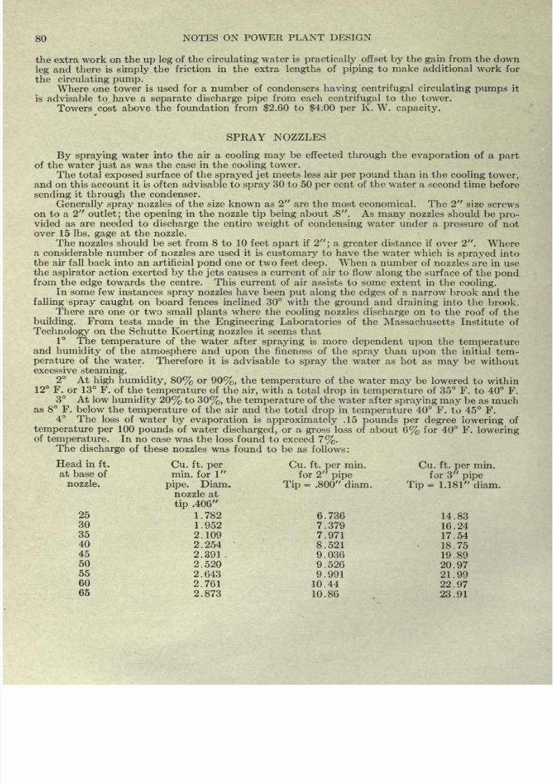
8/20/2019 notes on powerplant.pdf
http://slidepdf.com/reader/full/notes-on-powerplantpdf 86/202
80
NOTES
ON POWER
PLANT
DESIGN
the
extra work
on the
up
leg
of
the
circulating
water
is
practically
offset
by
the
gain
from
the
down
leg
and there
is
simply
the
friction
in
the extra
lengths
of
piping
to
make
additional
work
for
the
circulating
pump.
Where
one tower
is
used
for
a number of
condensers
having
centrifugal
circulating
pumps
it
is
advisable
to have
a
separate discharge
pipe
from
each
centrifugal
to
the
tower.
Towers cost
above
the
foundation
from
$2.60
to
$4.00
per
K.
W.
capacity.
SPRAY NOZZLES
By
spraying
water into
the
air
a
cooling
may
be
effected
through
the
evaporation
of
a
part
of
the
water
just
as
was
the
case
in
the
cooling
tower.
The total
exposed
surface
of
the
sprayed jet
meets less
air
per
pound
than in the
cooling
tower,
and on this account
it
is often
advisable to
spray
30 to 50
per
cent of
the
water
a
second
time
before
sending
it
through
the condenser.
Generally
spray
nozzles
of
the
size
known as
2
are
the
most economical.
The
2
size
screws
on to
a
2
outlet;
the
opening
in
the nozzle
tip being
about
.8 . As
many
nozzles
should
be
pro-
vided as
are
needed
to
discharge
the entire
weight
of
condensing
water
under
a
pressure
of
not
over
15 Ibs.
gage
at the
nozzle.
The
nozzles should be
set
from
8 to
10
feet
apart
if
2 ;
a
greater
distance
if
over
2 .
Where
a
considerable
number
of
nozzles
are
used
it is
customary
to have the
water
which is
sprayed
into
the
air fall
back
into
an artificial
pond
one or
two
feet
deep.
When
a
number
of
nozzles
are in
use
the
aspirator
action exerted
by
the
jets
causes
a
current of air to flow
along
the surface
of
the
pond
from
the
edge
towards
the
centre.
This
current of air
assists
to
some
extent
in
the
cooling.
In
some few
instances
spray
nozzles have been
put
along
the
edges
of a
narrow
brook
and
the
falling
spray caught
on
board fences inclined 30
with
the
ground
and
draining
into the
brook.
There
are
one or
two
small
plants
where
the
cooling
nozzles
discharge
on
to
the
roof
of
the
building.
From
tests made in
the
Engineering
Laboratories of
the
Massachusetts
Institute of
Technology
on the
Schutte
Koerting
nozzles it seems
that
1
The
temperature
of
the water
after
spraying
is
more
dependent
upon
the
temperature
and
humidity
of
the
atmosphere
and
upon
the fineness of
the
spray
than
upon
the
initial
tem-
perature
of the water.
Therefore
it
is
advisable to
spray
the
water
as
hot
as
may
be
without
excessive
steaming.
2
At
high
humidity,
80%
or
90%,
the
temperature
of
the water
may
be
lowered
to
within
12
F.
or
13
F. of
the
temperature
of
the
air,
with
a
total
drop
in
temperature
of
35
F.
to
40
F.
3
At low
humidity
20%
to
30%,
the
temperature
of the water after
spraying
may
be
as
much
as
8 F. below
the
temperature
of the
air
and
the
total
drop
in
temperature
40
F.
to
45
F.
4
The
loss of
water
by evaporation
is
approximately
.15
pounds
per
degree
lowering
of
temperature
per
100
pounds
of
water
discharged,
or
a
gross
loss
of
about
6%
for
40
F.
lowering
of
temperature.
In
no
case was the
loss
found to
exceed
7%.
The
discharge
of
these
nozzles was
found
to be as
follows:
Head hi
ft.
Cu.
ft.
per
Cu. ft.
per
min.
Cu.
ft.
per
min.
at
base
of
min.
for
1
for
2
pipe
for
3
pipe
nozzle.
pipe.
Diam.
Tip
=
.800
diam.
Tip
=
1.181
diam.
nozzle
at
tip
.406
25
1.782
6.736
14.83
30
1.952
7.379
16.24
35
2.109
7.971
17.54
40
2.254
8.521
18.75
45
2.391.
9.036
19.89
50
2.520
9.526
20.97
55
2.643
9.991
21.99
60
2.761
10.44
22.97
65
2.873
10.86 23.91
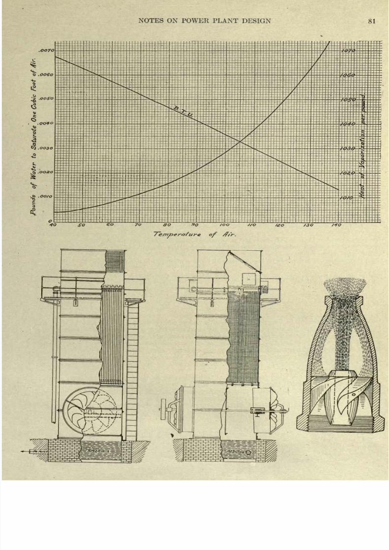
8/20/2019 notes on powerplant.pdf
http://slidepdf.com/reader/full/notes-on-powerplantpdf 87/202
NOTES ON
POWER PLANT
DESIGN
81
.OO7C
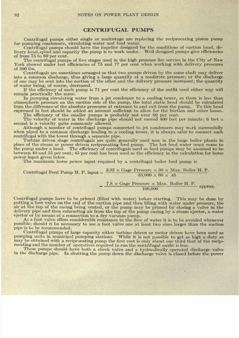
8/20/2019 notes on powerplant.pdf
http://slidepdf.com/reader/full/notes-on-powerplantpdf 88/202
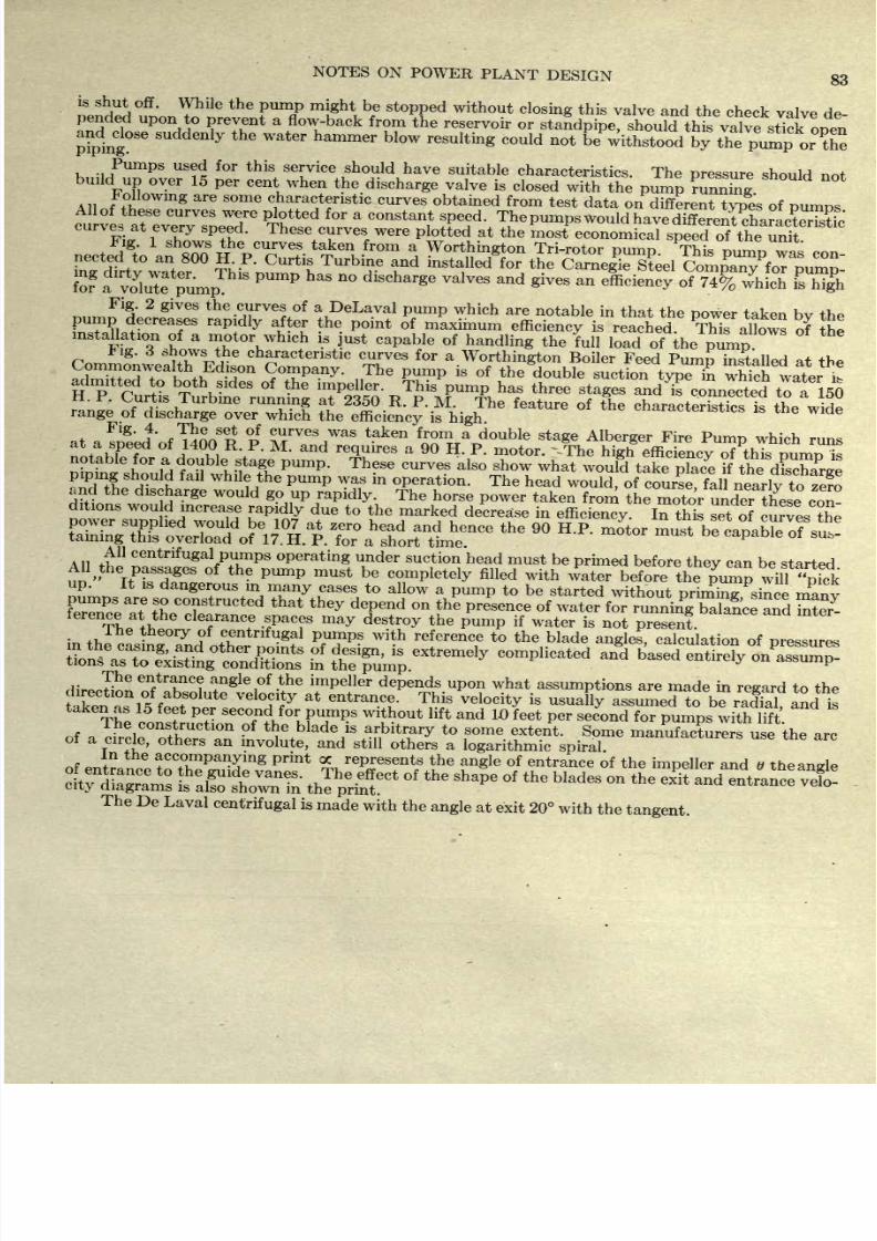
8/20/2019 notes on powerplant.pdf
http://slidepdf.com/reader/full/notes-on-powerplantpdf 89/202
NOTES
ON
POWER
PLANT
DESIGN
83
is
shut off.
While
the
pump
might
be
stopped
without
closing
this
valve
and
the
check
pended
upon
to
prevent
a
flow-back
from
the
reservoir
or
standpipe,
should
this
valve
and^dose
suddenly
the
water
hammer
blow
resulting
could
not
b^thstoodbythep
Pumps
used
for
this
service
should
have
suitable
characteristics.
The
pressure
should not
build
up
over
15
per
cent
when
the
discharge
valve
is
closed
with the
pump
mnnTng
llowing
are
some
characteristic
curves
obtained
from
test
data
on
different
types
of
Dumos
i^^t^^^
fo? a
dlr
vlTeTu
m
p
ThlS
PUmP
aS n
dbcharge
1VeS
and
*
an
SC3wSfc&
Mgh
Fig.
2
gives
the
curves
of
a
DeLaval
pump
which
are
notable
in
that the
power
taken
bv
the
piping
should
fail
while
the
pump
was
in
operation.
The
head
would,
of
course
fall
nearlv to zero
and
the
discharge
would
go
up
rapidly.
The
horse
power
taken
from
the
motor
under
Tlfese
con-
ditions
woud
increase
rapidly
due
to
the
marked
decrease
in
efficiency.
In
this
set
of
curves
the
t
is
dangerous
in
many
cases
to
allow
a
pump
to
be
started
without
priming
since
manv
The
con,tn,
P
^
seco
f
n
f,
for
P
U
P.
S
thout
lift
and
W
feet
per
second
for
pumps
with
lift
accom
pan
y
lng
represents
the
angle
of
entrance
of
the
impeller
and v
theangl
ftfiS
thl^f*
f
the
ShaPe
f
the
WadeS
-
the
exit
The
De
Laval
centrifugal
is
made
with
the
angle
at
exit 20
with
the
tangent.
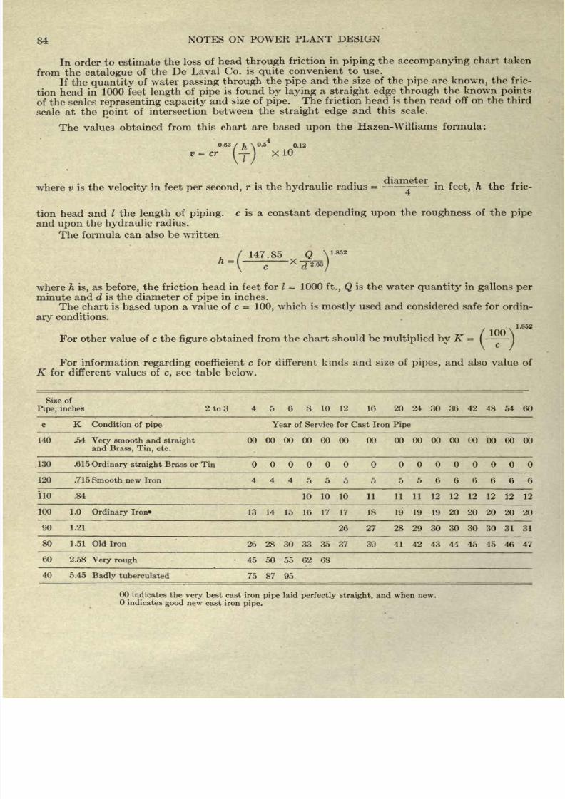
8/20/2019 notes on powerplant.pdf
http://slidepdf.com/reader/full/notes-on-powerplantpdf 90/202
84
NOTES
ON
POWER
PLANT DESIGN
In order
to
estimate
the
loss
of
head
through
friction
in
piping
the
accompanying
chart taken
from
the
catalogue
of
the
De
Laval
Co.
is
quite
convenient
to
use.
If
the
quantity
of
water
passing
through
the
pipe
and
the
size
of
the
pipe
are
known,
the
fric-
tion
head
in
1000
feet
length
of
pipe
is
found
by
laying
a
straight
edge
through
the
known
points
of
the
scales
representing
capacity
and
size of
pipe.
The
friction
head
is
then
read
off
on the
third
scale at
the
point
of
intersection
between the
straight
edge
and
this
scale.
The
values obtained
from
this
chart
are based
upon
the
Hazen-Williams
formula:
0.63
/fc\0.5
4
0.12
v
=
cr
l-r-\
X
10
where v
is the
velocity
in feet
per
second,
r is the
hydraulic
radius
=
-
-:
in
feet,
h
the
fric-
tion
head
and /
the
length
of
piping,
c is a constant
depending
upon
the
roughness
of the
pipe
and
upon
the
hydraulic
radius.
The formula
can
also
be
written
147.85
_Q_Y'
852
c
'
X
d
2
-
63
/
where
h
is,
as
before,
the
friction
head in
feet
for /
=
1000
ft., Q
is
the
water
quantity
in
gallons
per
minute and d
is the diameter of
pipe
in inches.
The chart
is
based
upon
a
value
of c
=
100,
which
is
mostly
used and considered safe for
ordin-
ary
conditions.
1.852
For
other
value
of c
the
figure
obtained from
the
chart
should be
multiplied
by
K
=
-
-
For
information regarding
coefficient
c
for
different
kinds
and
size of
pipes,
and
also
value
of
K for
different
values
of
c,
see table
below.
Size of
Pipe,
inches
2
to
3
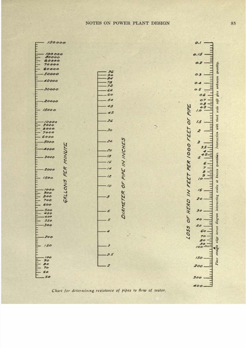
8/20/2019 notes on powerplant.pdf
http://slidepdf.com/reader/full/notes-on-powerplantpdf 91/202
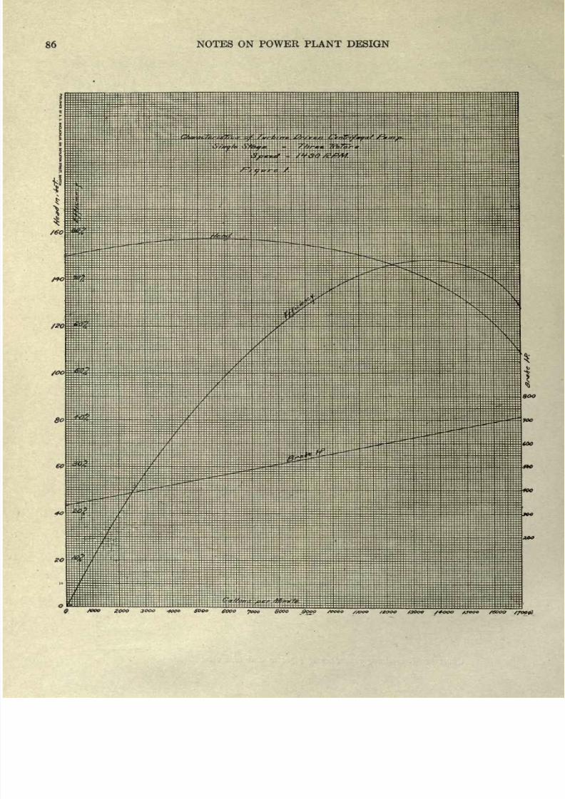
8/20/2019 notes on powerplant.pdf
http://slidepdf.com/reader/full/notes-on-powerplantpdf 92/202
86
NOTES
ON
POWER
PLANT
DESIGN
/eo
9
fooo
gooo
3000
4000
SDOO
fooo
fooo
8000
9000
seooo
,&oo
/gooo
aooo
/+ooo
*roeo /eooo
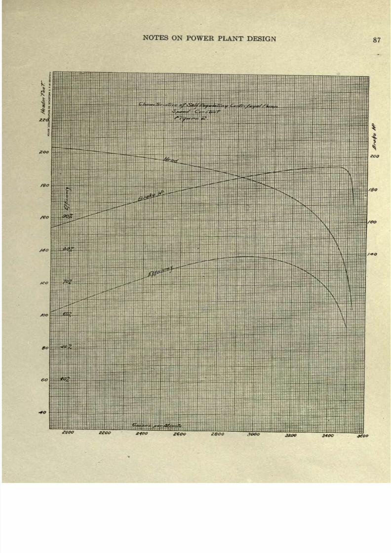
8/20/2019 notes on powerplant.pdf
http://slidepdf.com/reader/full/notes-on-powerplantpdf 93/202
NOTES
ON
POWER
PLANT
DESIGN
87
3KOO
3400
jffOO
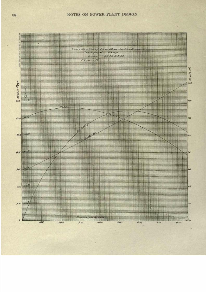
8/20/2019 notes on powerplant.pdf
http://slidepdf.com/reader/full/notes-on-powerplantpdf 94/202
88
NOTES
ON
POWER
PLANT
DESIGN
700
$00
500
400
300
ZOO
soo
if
/OQ
ZOO
3OQ
300
6OO
700
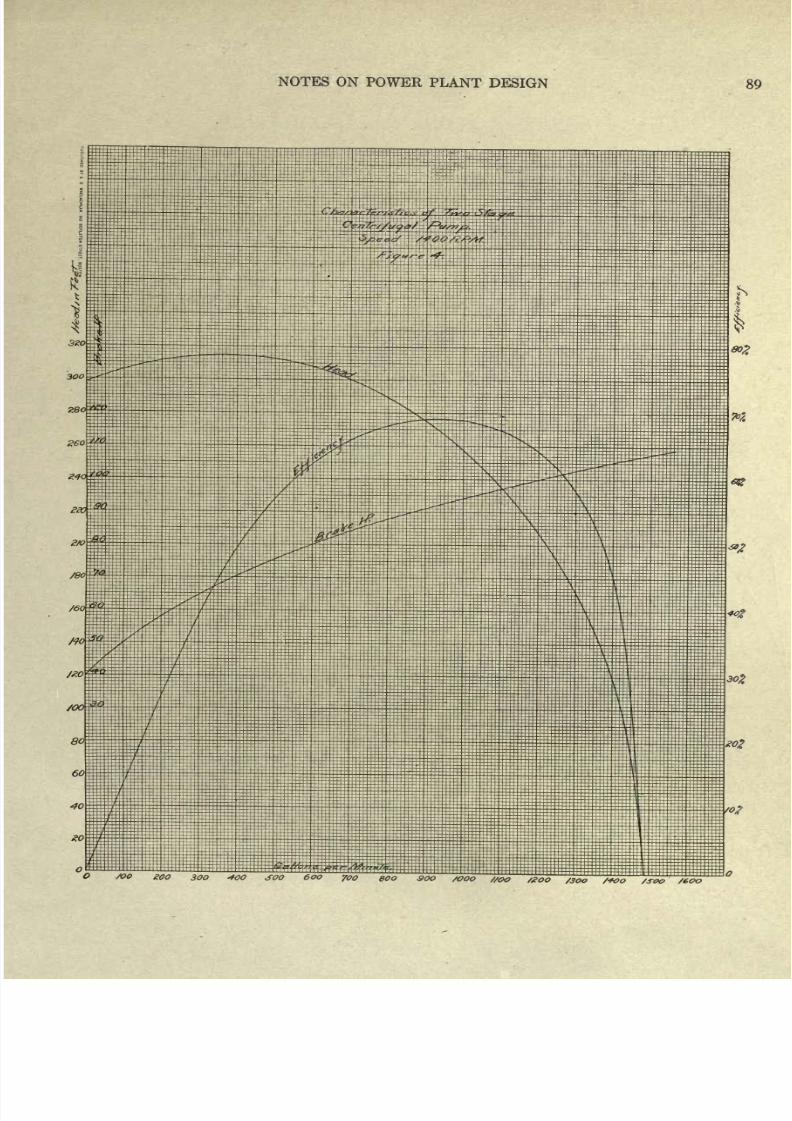
8/20/2019 notes on powerplant.pdf
http://slidepdf.com/reader/full/notes-on-powerplantpdf 95/202
NOTES
ON
POWER
PLANT
DESIGN
89
/3oo
/*co
/sexy
/6oo
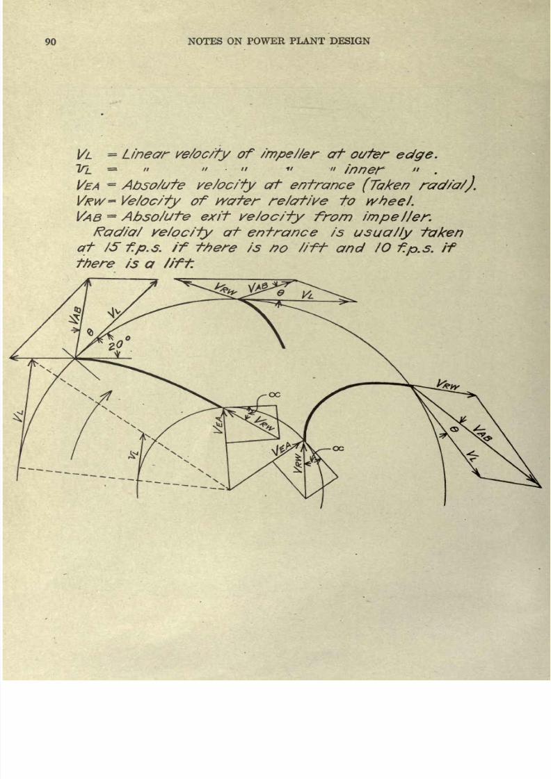
8/20/2019 notes on powerplant.pdf
http://slidepdf.com/reader/full/notes-on-powerplantpdf 96/202
90
NOTES
ON
POWER PLANT DESIGN
VL
=
Linear
ve/oc/fy
of
impeller
at
outer
edge.
T/L
=
//
// //
11
a
Inner
.
VEA
~
Abso/ufe
ve/oc/fy
at entrance
(Taken
rad/a/).
VRW=
Ve/oc/ty
of wafer
re/af/ve
to
wheel.
VAB
=
Absolute
exit
velocity
from
impeller.
Radial
ve/ociiy
at
entrance
is
usually
taken
at
IS
f.p.s.
if
there is
no
lift
and
IO
f.p.s.
if
there
is
a
lift.
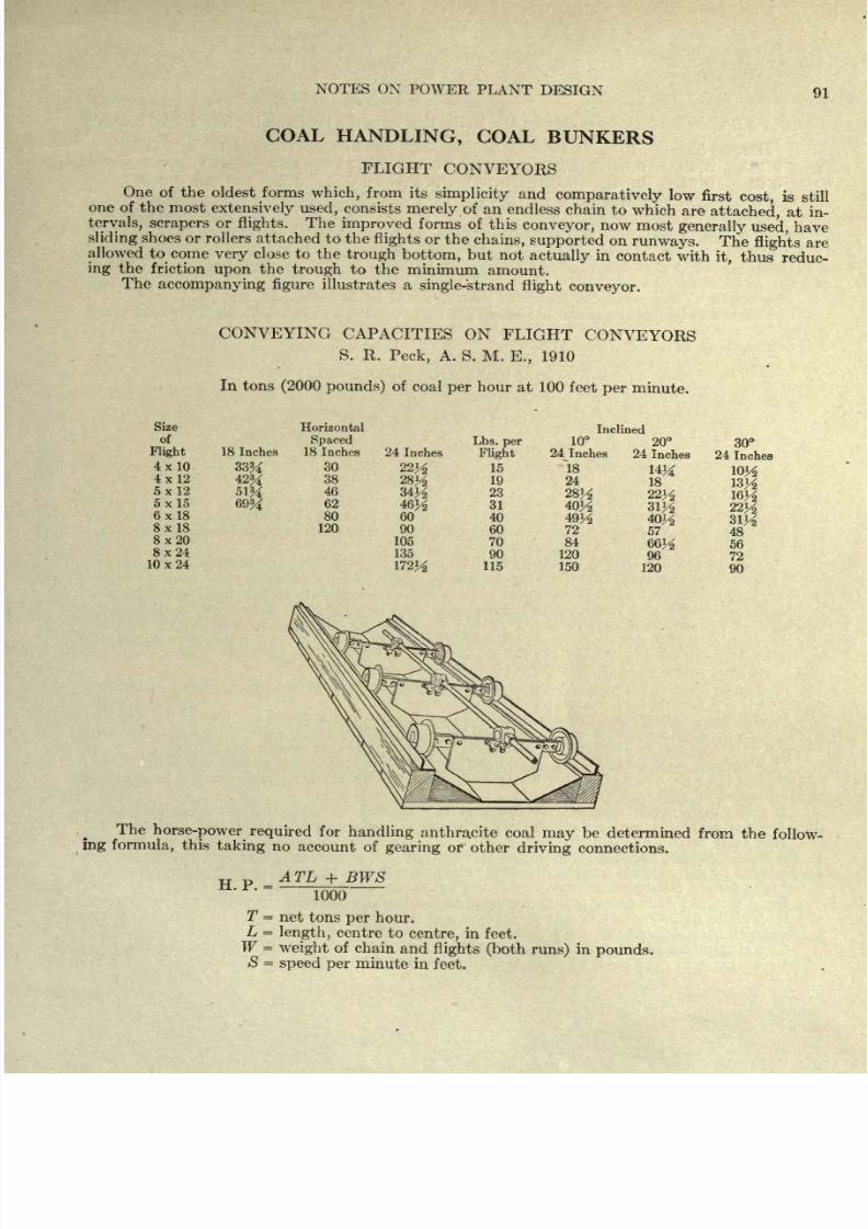
8/20/2019 notes on powerplant.pdf
http://slidepdf.com/reader/full/notes-on-powerplantpdf 97/202
NOTES
ON
POWER
PLANT
DESIGN
91
COAL
HANDLING,
GOAL
BUNKERS
FLIGHT
CONVEYORS
One
of
the
oldest
forms
which,
from
its
simplicity
and
comparatively
low
first
cost,
is
still
one
of
the most
extensively used,
consists
merely
of an
endless
chain
to
which are
attached,
at
in-
tervals,
scrapers
or
flights.
The
improved
forms
of
this
conveyor,
now
most
generally
used,
have
sliding
shoes
or
rollers
attached to
the
flights
or
the
chains,
supported
on
runways.
The
flights
are
allowed
to
come
very
close
to the
trough
bottom,
but
not
actually
in
contact
with
it,
thus
reduc-
ing
the
friction
upon
the
trough
to
the
minimum
amount.
The
accompanying
figure
illustrates
a
single-strand
flight
conveyor.
CONVEYING
CAPACITIES
ON
FLIGHT
CONVEYORS
S. R.
Peck,
A.
S.
M.
E.,
1910
In
tons
(2000
pounds)
of
coal
per
hour
at
100
feet
per
minute.
Size
of
Flight
4x10
4x12
5x12
5x15
6x18
8x
18
8x20
8x24
10x24
18
Inches
33%
69%
Horizontal
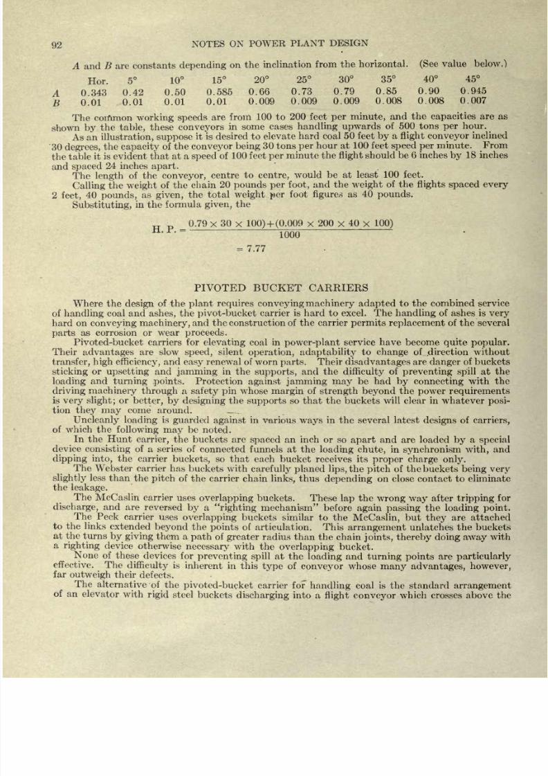
8/20/2019 notes on powerplant.pdf
http://slidepdf.com/reader/full/notes-on-powerplantpdf 98/202
92
NOTES
ON
POWER
PLANT
DESIGN
A
and
B are
constants
depending
on
the
inclination
from
the
horizontal.
(See
value
below.)
Hor.
5
10
15
20
25 30
35
40 45
A
343
0.42
0.50
0.585
0.66
0.73
0.79
0.85 0.90
0.945
B
0.01
0.01
0.01
0.01
0.009
0.009
0.009
0.008
0.008
0.007
The
common
working
speeds
are from
100
to
200 feet
per
minute,
and the
capacities
are as
shown
by
the
table,
these
conveyors
in
some
cases
handling
upwards
of
500
tons
per
hour.
As
an
illustration,
suppose
it
is
desired
to elevate
hard
coal
50
feet
by
a
flight
conveyor
inclined
30
degrees,
the
capacity
of the
conveyor
being
30 tons
per
hour
at 100
feet
speed
per
minute. From
the
table
it
is
evident
that
at a
speed
of
100
feet
per
minute the
flight
should
be
6
inches
by
18
inches
and
spaced
24
inches
apart.
The
length
of
the
conveyor,
centre
to
centre,
would
be
at
least
100
feet.
Calling
the
weight
of
the
chain
20
pounds
per
foot,
and the
weight
of
the
flights
spaced every
2
feet,
40
pounds,
as
given,
the
total
weight
per
foot
figures
as
40
pounds.
Substituting,
in
the
formula
given,
the
0.79
x
30
x
100)
+
(0.009
x
200
x
40
x
100)
1000
=
7.77
PIVOTED
BUCKET
CARRIERS
Where
the
design
of
the
plant
requires
convey
ing machinery adapted
to
the combined
service
of
handling
coal
and
ashes,
the
pivot-bucket
carrier
is hard
to
excel. The
handling
of
ashes
is
very
hard
on
conveying machinery,
and
the
construction
of
the carrier
permits
replacement
of
the
several
parts
as corrosion
or
wear
proceeds.
Pivoted-bucket
carriers
for
elevating
coal
in
power-plant
service have become
quite
popular.
Their
advantages
are
slow
speed,
silent
operation,
adaptability
to
change
of
.direction
without
transfer,
high efficiency,
and
easy
renewal
of worn
parts.
Their
disadvantages
are
danger
of
buckets
sticking
or upsetting
and
jamming
in
the
supports,
and
the
difficulty
of
preventing
spill
at
the
loading
and
turning
.points.
Protection
against
jamming
may
be
had
by connecting
with
the
driving machinery
through
a
safety pin
whose
margin
of
strength beyond
the
power requirements
is
very
slight
;
or
better,
by designing
the
supports
so
that
the
buckets
will
clear
in
whatever
posi-
tion
they may
come
around.
Uncleanly
loading
is
guarded
against
in
various
ways
in
the
several
latest
designs
of
carriers,
of
which
the
following may
be
noted.
In
the
Hunt
carrier,
the
buckets
are
spaced
an inch or
so
apart
and
are loaded
by
a
special
device
consisting
of
a series
of connected
funnels
at
the
loading chute,
in
synchronism
with,
and
dipping
into,
the
carrier
buckets,
so
that
each
bucket receives its
proper charge
only.
The
Webster
carrier has
buckets with
carefully planed
lips,
the
pitch
of
the buckets
being very
slightly
less
than
the
pitch
of
the
carrier
chain
links,
thus
depending
on
close
contact
to eliminate
the
leakage.
The
McCaslin
carrier
uses
overlapping
buckets.
These
lap
the
wrong
way
after
tripping
for
discharge,
and
are
reversed
by
a
righting
mechanism
before
again
passing
the
loading point.
The
Peck
carrier
uses
overlapping
buckets similar
to
the
McCaslin,
but
they
are attached
to
the
links
extended
beyond
the
points
of
articulation.
This
arrangement
unlatches
the
buckets
at
the
turns
by
giving
them
a
path
of
greater
radius
than the chain
joints,
thereby doing
away
with
a
righting
device
otherwise
necessary
with
the
overlapping
bucket.
None
of these
devices
for
preventing spill
at
the
loading
and
turning
points
are
particularly
effective.
The
difficulty
is
inherent
in
this
type
of
conveyor
whose
many advantages,
however,
far
outweigh
their
defects.
The
alternative
of the
pivoted-bucket
carrier
fof
handling
coal
is
the
standard
arrangement
of
an
elevator
with
rigid
steel
buckets
discharging
into a
flight conveyor
which crosses above the
8/20/2019 notes on powerplant.pdf
http://slidepdf.com/reader/full/notes-on-powerplantpdf 99/202
NOTES
ON
POWER
PLANT
DESIGN
93
bunkers,
and is
provided
with
discharge
gates
at
convenient
intervals;
or instead of a
flight
con-
veyor,
a
belt with
movable
tripper.
This
is
a
well
tried-out
system,
thoroughly reliable,
and
by
many
preferred
to
the run-around
carrier,
on
the
ground
of lower first cost
and
simpler
con-
struction.
The elevator
conveyor
system
is not
adapted
to
handling
ashes,
which,
however,
should
be
t:.ken care
of
by
separate
machinery
whenever
possible
to
do
so.
Diagram
Showing
Operation
of
the
Peck
Carrier
The
general
arrangement
of a
rectangular
pivoted
bucket
conveyor
is
shown
by
the accom-
panying
cut.
Coal
discharged
from
a car
or from
a
cart
falls
into
a
crusher
where
the
large
lumps
are
broken
up.
From
the
crusher
the coal
is
taken
directly
into the
conveyor
or into
the
feeding
mechanism'
which
fills
the
conveyor.
Somewhere
in the
system
there
must be a
tightener,
which
in
this cut is
shown
as
located
at
the lower right-hand
corner.
_
The
reciprocating
feeder
consists
simply
of
a
movable
plate,
at
the
bottom
of the
hopper,
which is
pushed
forward
and
back
through
the
action of an
eccentric.
On
the
forward
stroke
coal
is
fed
into the crusher.
The
length
of
the
plate
is
such
that
coal
in
the
hopper
will
not
flow
over
the
left-hand
edge
when the
feeding
plate
is still.
When
coal is
discharged
directly
through
the
track
hopper,
feeder
and
crusher
into
the con-
veyor
buckets
as
shown
in the
cut,
the
track
must be
from 10
to
12
feet
above
the
bottom
run
of
the
conveyor.
Where
there is
not
sufficient
depth
for
this
arrangement
an
apron
feeder
(see
illustration)
would
be
used
to elevate the coal
to
the
crusher.
The
speed
of
the
apron
must
be
regulated
to
suit
the
capacity
of
the
carrier
or
a
reciprocat-
ing
feeder
may
be
inserted
between
the
hopper
and the
apron.
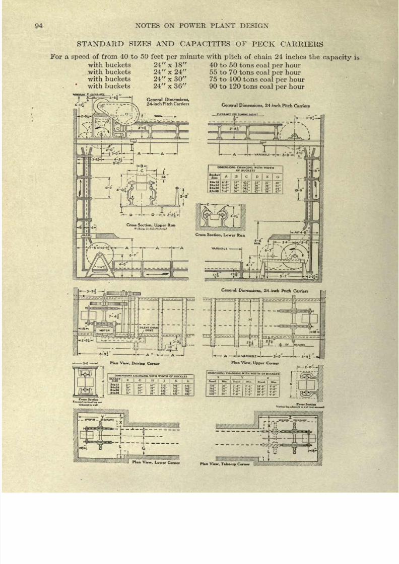
8/20/2019 notes on powerplant.pdf
http://slidepdf.com/reader/full/notes-on-powerplantpdf 100/202
94
NOTES
ON POWER
PLANT
DESIGN
STANDARD
SIZES
AND
CAPACITIES
OF
PECK
CARRIERS
For
a
speed
of
from 40 to
50
feet
per
minute with
pitch
of
chain
24 inches the
capacity
is
with
buckets
24
x
18
40 to 50
tons
coal
per
hour
with
buckets 24
x
24 55
to 70
tons coal
per
hour
with
buckets
24 x 30
75
to 100
tons
coal
per
hour
with
buckets
.
24
x
36 90
to
120
tons coal
per
hour
TM
CLUMMCt
/
s
~
General
Dimensions,
- i
( (tjT^
' -
-'-
- 1>
24-inch
Pitch
Carriers
General
Dimensions,
24-inch
Pitch
Carriers
ClCARAUCe
FOB
DUMPING I
General
Dimensions,
24-
inch Pitch
Carriers
DIMENSIONS
CHANCING
WITH
WIDTH
OF
BUCKETS
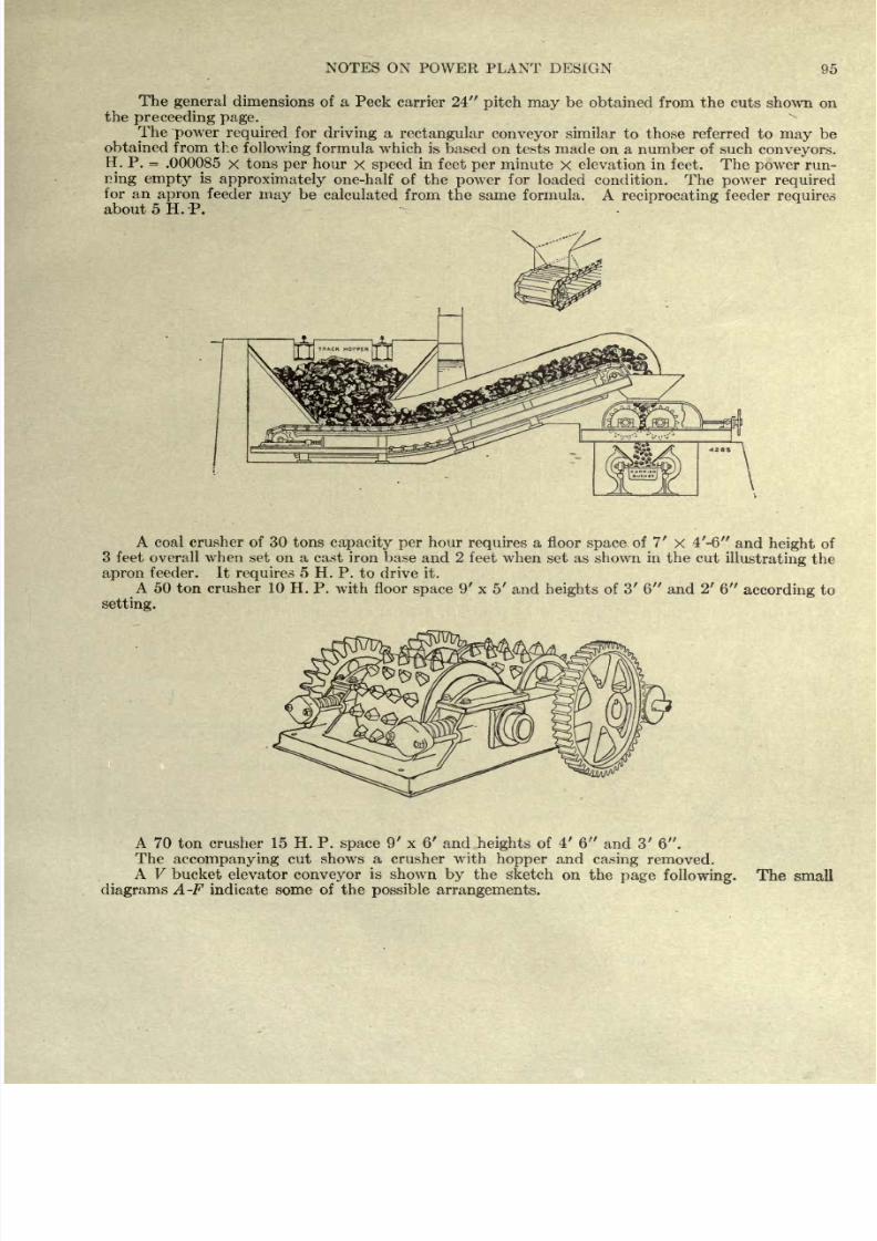
8/20/2019 notes on powerplant.pdf
http://slidepdf.com/reader/full/notes-on-powerplantpdf 101/202
NOTES
ON
POWER
PLANT
DESIGN
95
The
general
dimensions
of a
Peck
carrier
24
pitch may
be
obtained
from the
cuts
shown
on
the
preceeding
page.
The
power
required
for
driving
a
rectangular conveyor
similar
to
those
referred
to
may
be
obtained from
the
following
formula which
is
based on tests
made
on
a number of
such
conveyors.
H. P.
=
.000085
x
tons
per
hour
x
speed
in feet
per
minute
X
elevation in
feet.
The
power
run-
ning
empty
is
approximately
one-half
of
the
power
for
loaded
condition.
The
power
required
for
an
apron
feeder
may
be
calculated
from
the
same
formula.
A
reciprocating feeder
requires
about
5
H.
P.
A coal
crusher
of 30
tons
capacity
per
hour
requires
a
floor
space
of
7'
X
4'-6
and
height
of
3
feet
overall when
set on
a
cast iron base
and
2
feet when
set as
shown
in
the
cut
illustrating
the
apron
feeder.
It
requires
5
H.
P.
to drive it.
A
50
ton
crusher 10
H.
P. with floor
space
9' x 5'
and
heights
of
3' 6
and
2'
6
according
to
setting.
A
70
ton
crusher 15 H. P.
space
9' x 6'
and
heights
of
4'
6
and
3'
6 .
The
accompanying
cut
shows
a
crusher
with
hopper
and
casing
removed.
A V
bucket elevator
conveyor
is
shown
by
the sketch
on
the
page
following,
diagrams
A-F
indicate
some
of
the
possible
arrangements.
The
small
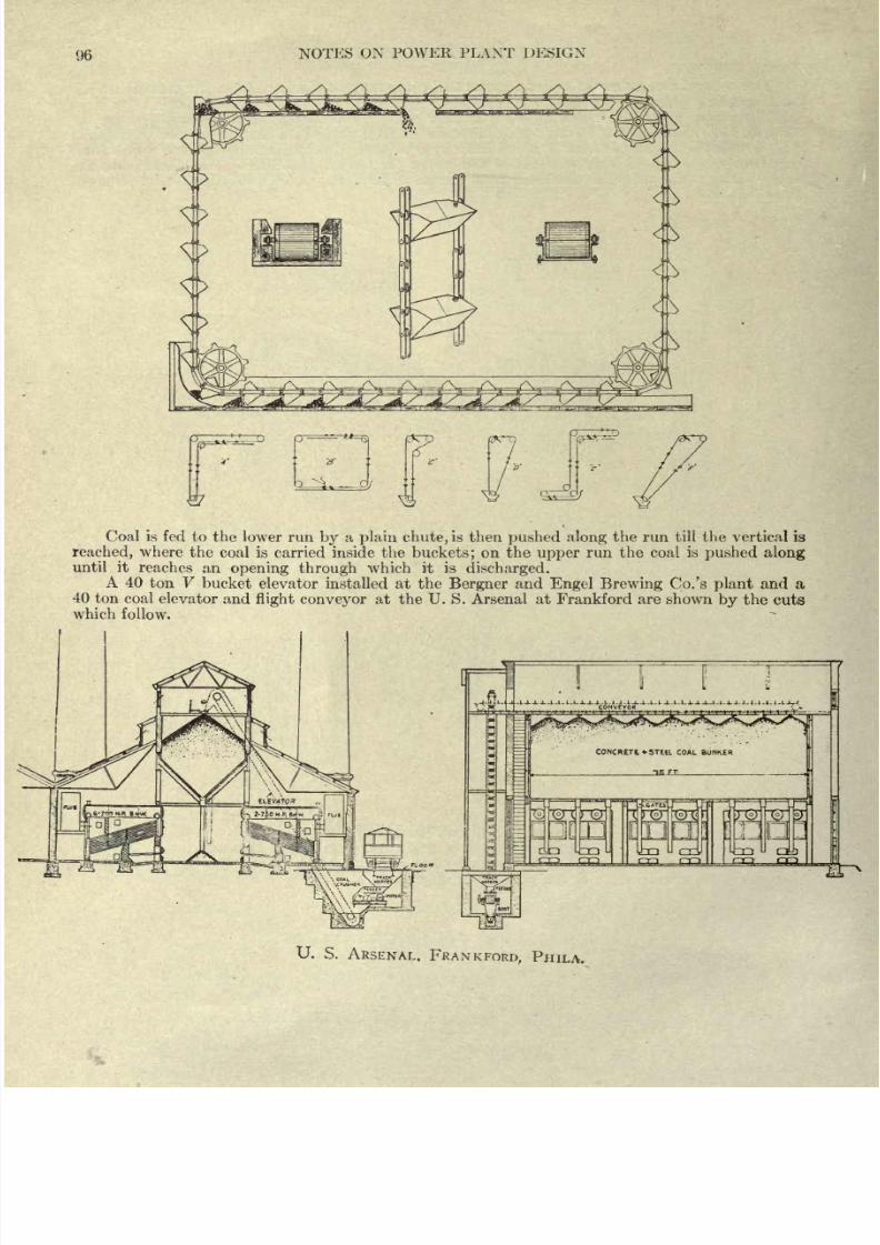
8/20/2019 notes on powerplant.pdf
http://slidepdf.com/reader/full/notes-on-powerplantpdf 102/202
96
NOTES
ON POWER FLAXT
DESIGN
Coal
is fed to
the
lower run
by
a
plain chute,
is then
pushed
along
the run
till the
vertical is
reached,
where
the
coal
is
carried
inside the
buckets;
on
the
upper
run the
coal
is
pushed along
until it
reaches
an
opening through
which
it
is
discharged.
A
40
ton
V
bucket
elevator
installed at
the
Bergner
and
Engel Brewing
Co.'s
plant
and a
40
ton
coal
elevator
and
flight
conveyor
at
the
U.
S.
Arsenal
at
Frankford
are
shown
by
the
cuts
which
follow.
U.
S.
ARSENAL.
FRANKFORD,
PHILA.
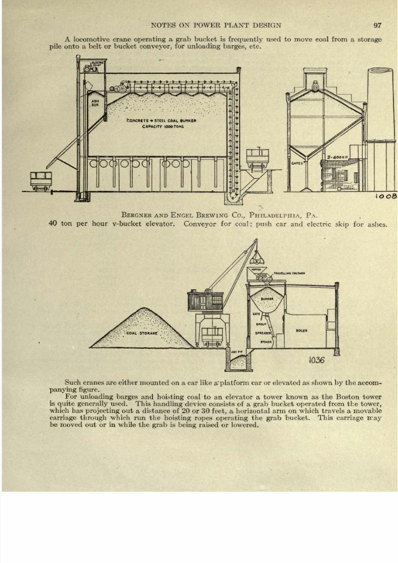
8/20/2019 notes on powerplant.pdf
http://slidepdf.com/reader/full/notes-on-powerplantpdf 103/202
NOTES
ON
POWER
PLANT DESIGN
97
A
locomotive
crane
operating
a
grab
bucket
is
frequently
used to
move eoal
from
a
storage
pile
onto
a
belt
or
bucket
conveyor,
for
unloading
barges,
etc.
oo8>
BERGNER
AND ENGEL
BREWING
Co.,
PHILADELPHIA,
PA.
40
ton
per
hour v-bucket
elevator.
Conveyor
for
coal
;
push
car
and
electric
skip
for
ashes.
Such
cranes
are
either
mounted
on a car like
a'
platform
car
or
elevated as
shown
by
the
accom-
panying figure.
For
unloading barges
and
hoisting
coal
to
an
elevator
a
tower
known as
the
Boston tower
is
quite
generally
used.
This
handling
device
consists of
a
grab
bucket
operated
from the
tower,
which has
projecting
out a distance of 20
or 30
feet,
a
horizontal
arm
on
which travels
a
movable
carriage
through
which
run
the
hoisting
ropes
operating
the
grab
bucket.
This
carriage
rray
be moved
out
or
in
while
the
grab
is
being
raised
or
lowered.
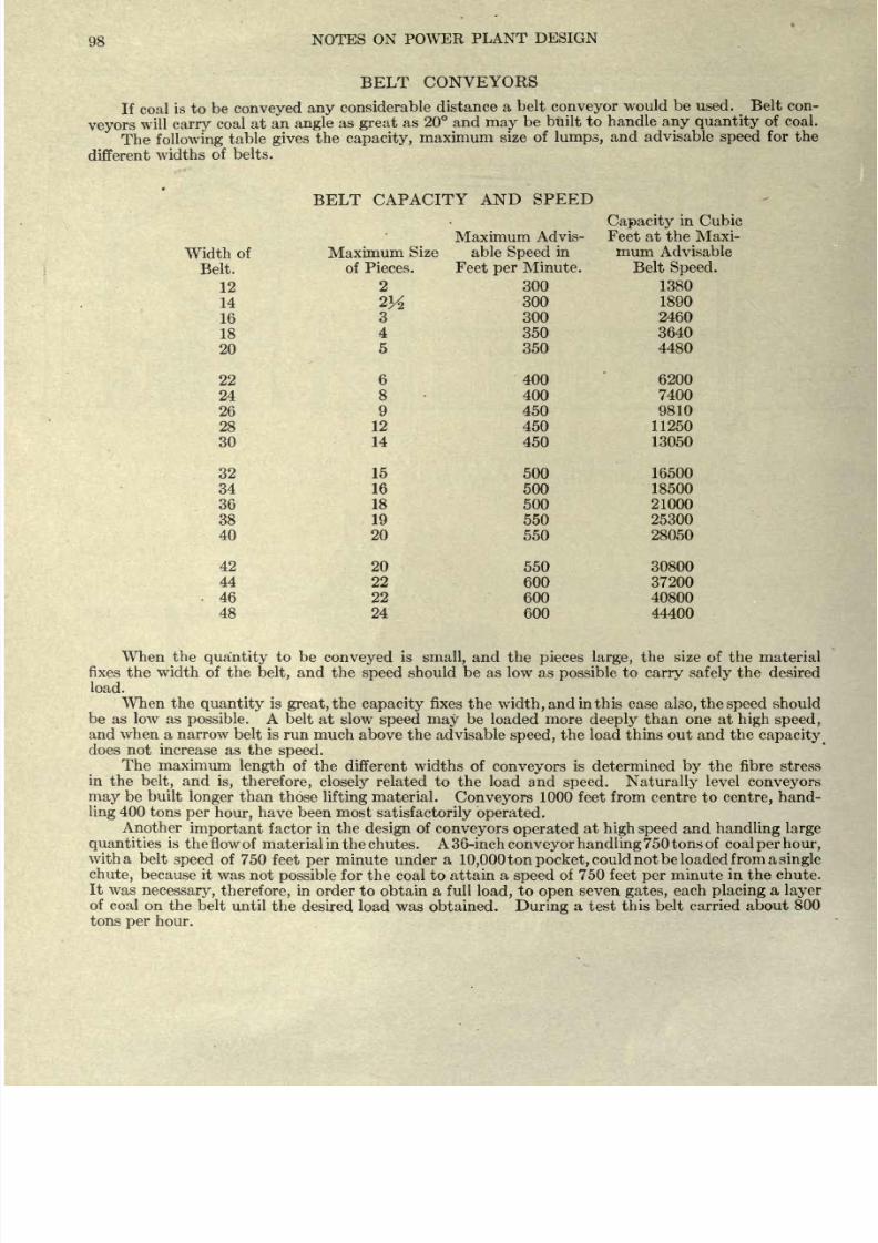
8/20/2019 notes on powerplant.pdf
http://slidepdf.com/reader/full/notes-on-powerplantpdf 104/202
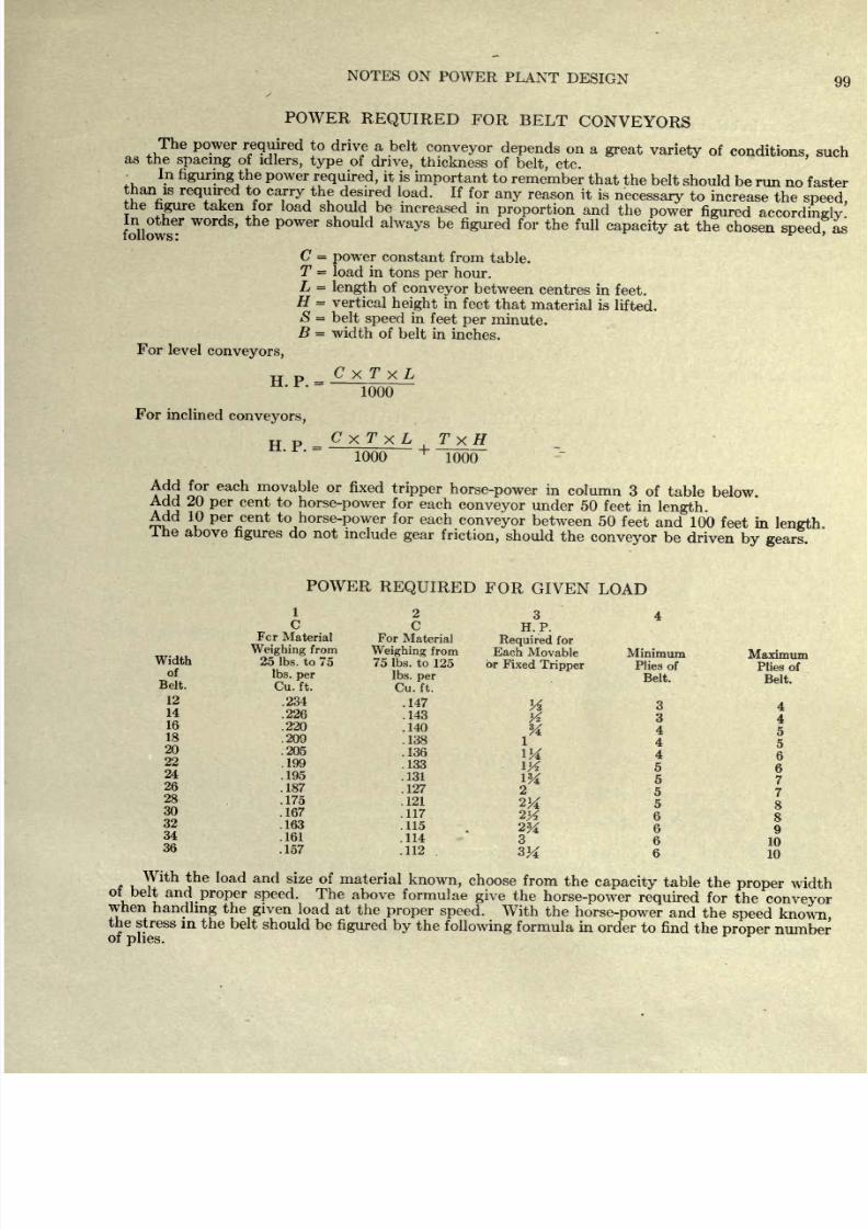
8/20/2019 notes on powerplant.pdf
http://slidepdf.com/reader/full/notes-on-powerplantpdf 105/202
NOTES
ON
POWER
PLANT
DESIGN
99
x
POWER
REQUIRED
FOR
BELT
CONVEYORS
The
power
required
to
drive a
belt
conveyor
depends
on
a
great
variety
of
conditions,
such
as
the
spacing
of
idlers,
type
of
drive,
thickness
of
belt,
etc.
_
In
figuring
the
power
required,
it
is
important
to
remember
that
the
belt
should
be
run
no
faster
than
is
required
to
carry the
desired
load.
If
for
any
reason
it is
necessary
to
increase
the
speed,
the
hgure
taken
for
load
should be
increased
in
proportion
and
the
power
figured accordingly
follows
61
W
P
Wer
alWayS
be
figUred
f
r
the
fuU
capacit
y
at the
chosen
speed,
as
C
=
power
constant
from
table.
T
=
load
in
tons
per
hour.
L
=
length
of
conveyor
between
centres
in
feet.
H
=
vertical
height
in
feet
that
material
is
lifted.
S
=
belt
speed
in
feet
per
minute.
B
=
width
of
belt in
inches.
For
level
conveyors,
TT
p
C
x
T
x
L
~Toob~
For
inclined
conveyors,
H
P
=
CxTxL
TxH
1000
1000
Add
for
each
movable
or
fixed
tripper
horse-power
in
column
3
of
table
below.
Add
20
per
cent
to
horse-power
for
each
conveyor
under
50
feet in
length.
Add 10
per
cent
to
horse-power
for
each
conveyor
between
50
feet
and
100
feet
in
length
I he
above
figures
do
not
include
gear
friction,
should
the
conveyor
be
driven
by
gears.
POWER
REQUIRED
FOR
GIVEN
LOAD
1234
H.
P.
Fcr
Material
For
Material
Required
for
THT.UI.
^
g ing
*
fr
2 P
Weighing
from
Each
Movable
Minimum
Maximum
Width
25 Ibs. to
75
75 Ibs.
to
125
or
Fixed
Tripper
Plies
of
Plies of
Bdt.
&.
T
Belt'
^.t.
12
.234
.147
y
3
4
14
.226
.143
16
.220
.140
&
18
.209
.138
1
20
.205
.136
1M
4
6
22
.199
.133
\%
5
g
24
.195
.131
1%
5
7
26
.187 .127
2
7
28
.175
.121
2& 8
30
.167
.117
Q
32
.163
.115
2K
9
34
.161
.114
3
6
10
36
-157
.112
3^
6
10
With
the
load
and
size
of
material
known,
choose
from
the
capacity
table
the
proper
width
ot
belt
and
proper
speed.
The
above
formulae
give
the
horse-power
required
for
the
conveyor
when
handling
the
given
load
at
the
proper
speed.
With
the
horse-power
and
the
speed
known
the
stress
m
the
belt
should be
figured
by
the
following
formula
in
order
to
find
the
proper
number
of
plies.
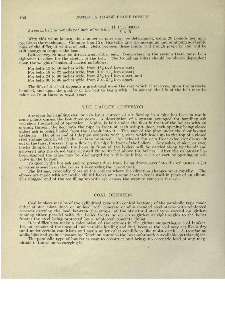
8/20/2019 notes on powerplant.pdf
http://slidepdf.com/reader/full/notes-on-powerplantpdf 106/202
100
NOTES
ON POWER
PLANT DESIGN
H. P.
X
33000
Stress
in belt
in
pounds
per
inch
of
width
=
$
v
B
With
this
value
known,
the
number
of
plies
may
be
determined,
using
20
pounds
per
inch
per
ply
as the
maximum.
Columns
4
and 5
of
this
table
give
the
maximum
and
minimum
advisable
plies
of
the
different
widths
of
belt.
Belts
between
these limits
will
trough
properly
and
will
be
stiff
enough
to
support
the
load.
Belt
conveyors
may
be driven
from
either
end.
Somewhere
in
the
system
there
must
be a
tightener
to
allow
for
the
stretch
of
the
belt.
The
troughing
idlers should be
placed
dependent
upon
the
weight
of
material
carried
as
follows:
For
belts
12 to
16
inches
wide,
from
4^
to
5 feet
apart;
For belts
18
to
22 inches
wide,
from
4
to
4
Y^
feet
apart;
For belts
24 to
30 inches
wide,
from
3^
to
4
feet
apart,
and
For
belts
30 to
36 inches
wide,
from
3 to
3]/2
feet
apart.
The
life of
the
belt
depends
a
great
deal
upon
the
care
which
it
receives, upon
the
material
handled,
and
upon
the
quality
of
the belt
to
begin
with.
In
general
the
life of
the
belt
may
be
taken
as
from
three
to
eight
years.
THE
DARLEY
CONVEYOR
A
system
for
handling
coal
or
ash
by
a
current
of air
flowing
in
a
pipe
has
been in
use
in
some
plants
during
the
last three
years.
A
description
of a
system
arranged
for
handling
ash
will
show
the
method
of
operation.
A
pipe
is
laid
under
the floor
in
front
of
the
boilers
with
an
opening
through
the
floor
into the
pipe
in front of
each
ash-pit
door,
each
opening
being
closed
unless ash
is
being
hauled from
the
ash-pit
into
it. The
end
of
the
pipe
under
the floor is
open
to
the
air.
The other
end of
this
pipe
connects with
a,
riser which leads
up
to
the
top
of
a closed
steel
storage
tank
in
which the
ash
is
to be stored. An exhaust
fan
or
a Root exhauster draws air
out
of the
tank,
thus
creating
a
flow
in the
pipe
in
front
of
the
boilers.
Any ashes,
clinker,
or
even
bricks
dumped
in
through
the
holes
in front of the boilers
will be carried
along
by
the air
and
delivered
into
the closed tank
elevated
20
to
40 feet
above
the boilers.
After
the exhauster
has
been
stopped
the ashes
may
be
discharged
from this tank into
a
car
or cart
by
opening
an
ash
valve
in the bottom.
To
quench
the
hot
ash and to
prevent
dust from
being
drawn
over
into the
exhauster,
a
jet
of
water is
sent in on
the
ash
as
it
is
entering
the
closed tank.
The
fittings,
especially
those
at
the
corners
where the
direction
changes
wear
rapidly.
The
elbows
are
made
with
renewable chilled backs or in some cases a tee
is
used
in
place
of
an
elbow.
The
plugged
end of
the tee
filling
up
with
ash
causes
the
wear
to come
on
the ash.
COAL
BUNKERS
Coal
bunkers
may
be of
the
cylindrical
type
with conical
bottom
;
of
the
parabolic
type
made
either
of
steel
plate
lined
or unlined
with
concrete
or
of
suspended
steel
straps
with reinforced
concrete
carrying
the
load between
the
straps,
of
the
structural steel
type
carried
on
girders
running
either
parallel
with the boiler
fronts
or
on
cross
girders
at
right angles
to
the boiler
fronts;
the
steel
being
protected
by
a
reinforced concrete
lining.
It
is
difficult
to make a calculation
of
the
stresses
in the
girders
supporting
a
coal
bunker,
1st,
on
account of the
unequal
and
variable
loading
and
2nd,
because the
coal
may
act
like a
dry
sand
under
certain
conditions
and
again
under other conditions
like
moist
earth. A
treatise on
walls,
bins and
grain
elevators
by
Ketchum contains
the best
information
available
on this
subject.
The
parabolic
type
of
bunker is
easy
to
construct
and
brings
no eccentric
load of
any
mag-
nitude
to
the
columns
carrying
it.
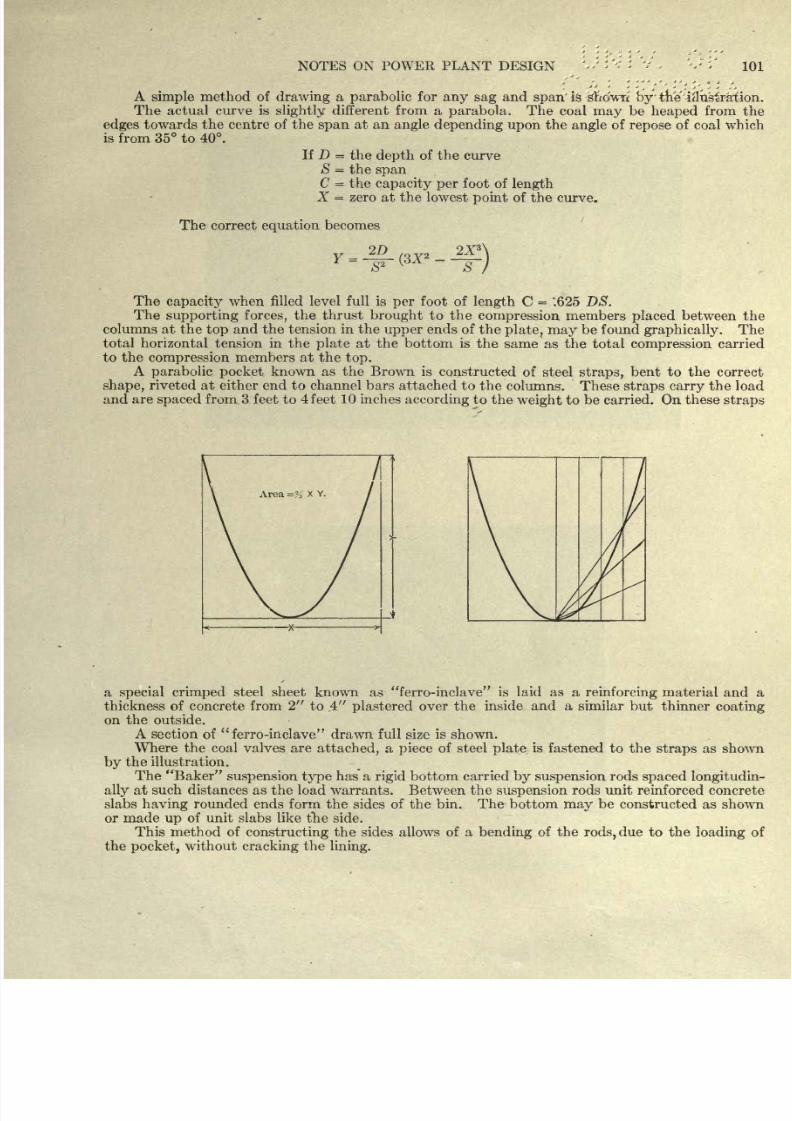
8/20/2019 notes on powerplant.pdf
http://slidepdf.com/reader/full/notes-on-powerplantpdf 107/202
101
A
simple
method of
drawing
a
parabolic
for
any
sag
and
span'
is -'gndwn
bytne
iilusirafion.
The
actual
curve
is
slightly
different
from a
parabola.
The coal
may
be
heaped
from the
edges
towards the centre of
the
span
at
an
angle
depending
upon
the
angle
of
repose
of coal which
is
from
35 to 40.
If
D
=
the
depth
of
the
curve
S
=
the
span
C
=
the
capacity per
foot
of
length
X
=
zero
at
the
lowest
point
of
the
curve.
The
correct
equation
becomes
S
The
capacity
when
filled level full is
per
foot
of
length
C
=
'.625 DS.
The
supporting
forces,
the
thrust
brought
to
the
compression
members
placed
between the
columns
at
the
top
and
the tension
in
the
upper
ends
of
the
plate,
may
be
found
graphically.
The
total horizontal
tension
in the
plate
at
the
bottom
is
the
same as
the total
compression
carried
to
the
compression
members
at
the
top.
A
parabolic
known
as
the
Brown
is
constructed of
steel
straps,
bent to the
correct
shape,
riveted
at either
end
to channel bars
attached
to
the
columns.
These
straps
carry
the load
and
are
spaced
from
3
feet
to
4
feet
10
inches
according
to the
weight
to
be
carried. On
these
straps
a
special
crimped
steel sheet
known
as
ferro-inclave
is laid
as
a
reinforcing
material
and a
thickness
of
concrete from
2
to
.4
plastered
over
the
inside
and a
similar
but
thinner
coating
on
the
outside.
A
section
of
ferro-inclave
drawn
full
size
is shown.
Where
the coal
valves
are
attached,
a
piece
of steel
plate
is
fastened to
the
straps
as
shown
by
the
illustration.
The
Baker
suspension type
has
a
rigid
bottom
carried
by suspension
rods
spaced
longitudin-
ally
at
such
distances as
the
load
warrants.
Between
the
suspension
rods
unit
reinforced
concrete
slabs
having
rounded
ends form
the
sides
of the bin.
The bottom
may
be constructed
as
shown
or made
up
of
unit
slabs like
the
side.
This method
of
constructing
the
sides
allows of a
bending
of the
rods,
due
to the
loading
of
the
pocket,
without
cracking
the
lining.
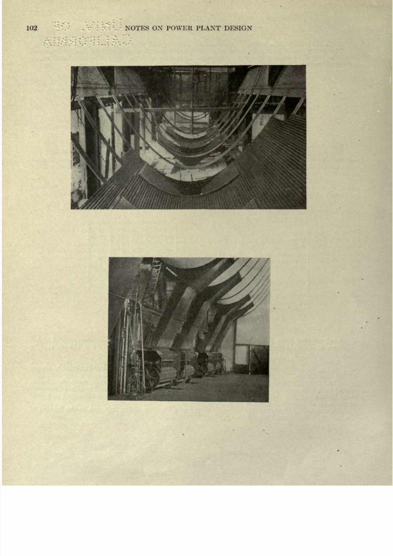
8/20/2019 notes on powerplant.pdf
http://slidepdf.com/reader/full/notes-on-powerplantpdf 108/202
102
NOTES
ON POWER PLANT
DESIGN
.
- -
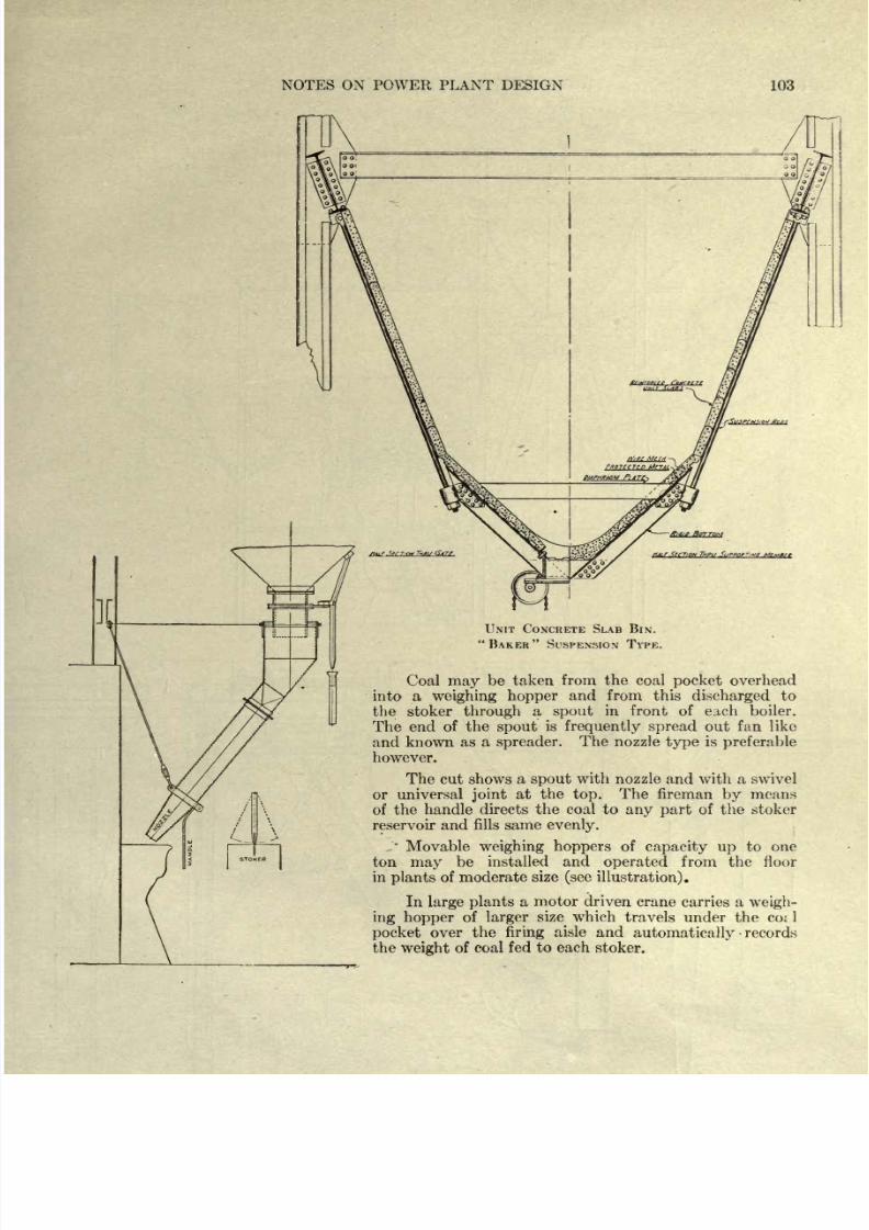
8/20/2019 notes on powerplant.pdf
http://slidepdf.com/reader/full/notes-on-powerplantpdf 109/202
NOTES
ON
POWER PLANT
DESIGN
103
UNIT
CONCRETE SLAB
BIN.
BAKER
SUSPENSION TYPE.
Coal
may
be
taken
from
the
coal
overhead
into a
weighing
hopper
and
from
this
discharged
to
the
stoker
through
a
spout
in front
of
each boiler.
The
end of
the
spout
is
frequently
spread
out
fan
like
and
known
as
a
spreader.
The
nozzle
type
is
preferable
however.
The cut
shows
a
spout
with
nozzle
and with
a
swivel
or
universal
joint
at
the
top.
The
fireman
by
means
of
the
handle
directs the
coal
to
any part
of the
stoker
reservoir
and fills same
evenly.
Movable
weighing hoppers
of
capacity up
to
one
ton
may
be
installed
and
operated
from the
floor
in
plants
of
moderate
size
(see
illustration).
In
large
plants
a motor
driven
crane
carries a
weigh-
ing
hopper
of
larger
size
which
travels
under
the
coi
1
over
the
firing
aisle
and
automatically
records
the
weight
of
coal
fed to each
stoker.
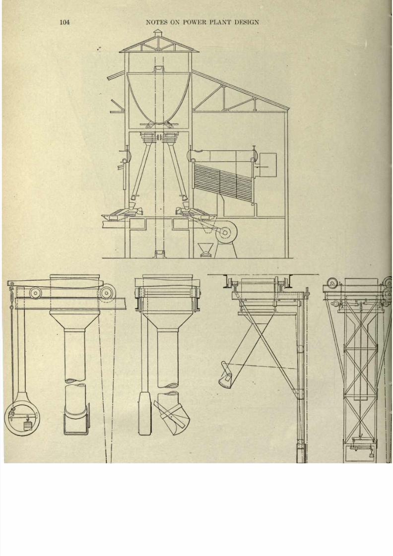
8/20/2019 notes on powerplant.pdf
http://slidepdf.com/reader/full/notes-on-powerplantpdf 110/202
104
NOTES
ON
POWER PLANT
DESIGN
LfeT
I
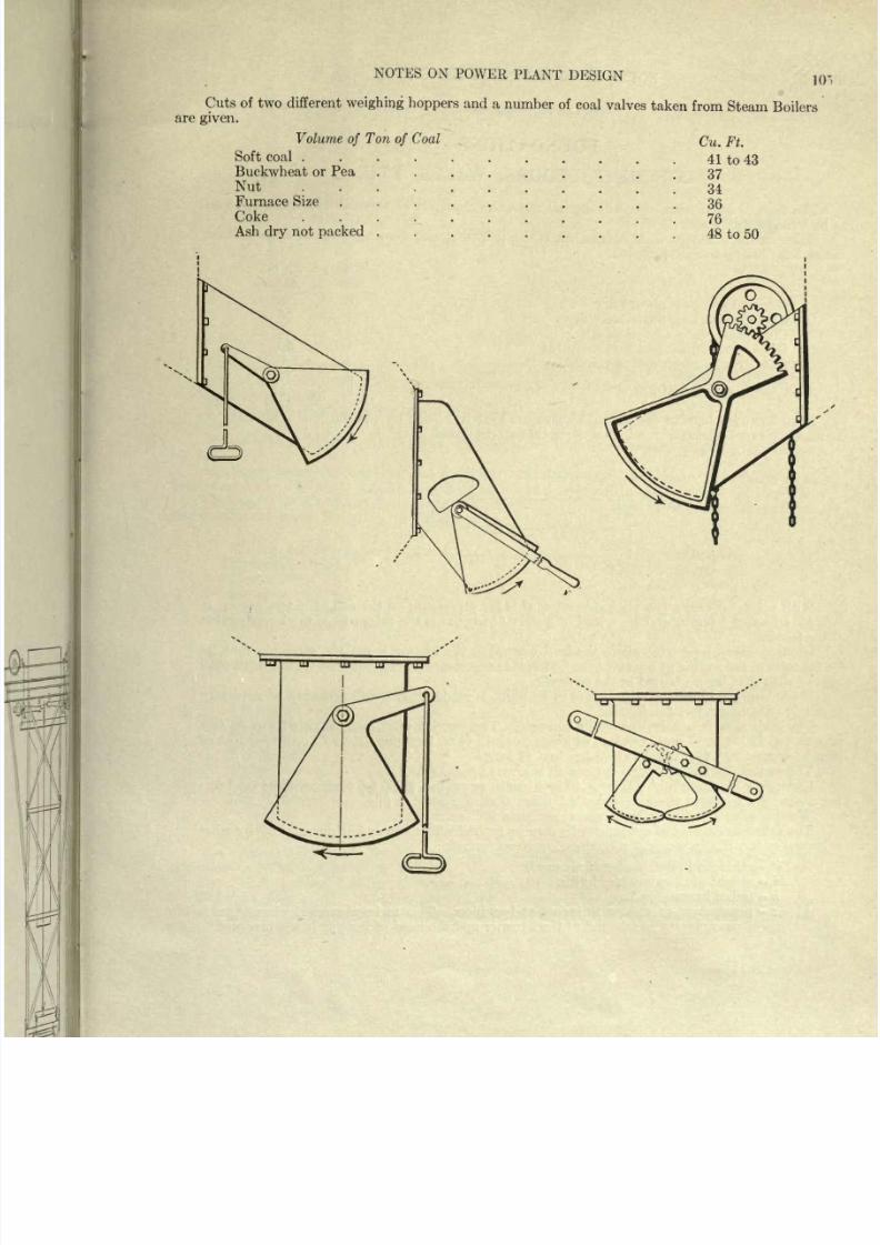
8/20/2019 notes on powerplant.pdf
http://slidepdf.com/reader/full/notes-on-powerplantpdf 111/202
NOTES
ON
POWER
PLANT
DESIGN
10-
Cuts of two different
weighing
hoppers
and a
number of
coal
valves
taken
from
Steam
Boilers
are
given.
Volume
of
Ton
of
Coal
Cu.
Ft.
Soft
coal
....
41
to
43
Buckwheat or
Pea
Nut
...
Furnace
Size
Coke
Ash
dry
not
packed
.
37
34
36
76
48 to
50
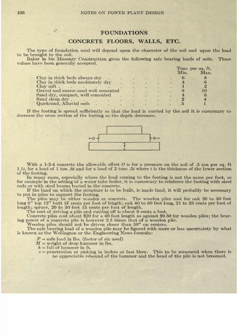
8/20/2019 notes on powerplant.pdf
http://slidepdf.com/reader/full/notes-on-powerplantpdf 112/202
8/20/2019 notes on powerplant.pdf
http://slidepdf.com/reader/full/notes-on-powerplantpdf 113/202
NOTES
ON
POWER
PLANT
DESIGN
107
If
there
is
a rebound
the
drop
of
hammer
should
be
reduced.
2Mh
;
TTT
Illustration
Hammer
=
3000
Ibs.
Drop
in
ft.
=
10
p
=
15,000
Ibs.
Penetration
=
3
BRICKS
A
mason
and
laborer
will
lay
1000
to
1500
bricks
per
day
in
a
wall
averaging
10
to
12
thick.
The
cost
of
labor
per
1000
bricks
laid,
including
mason
and
helper
and
cost
of
erecting
stagings
is from
$8.00
to
$8.50.
Bricks
cost from
$7.50
to
$10.00
per
1000
and
a
thousand bricks
will
lay
about
2
cubic
yards
of
masonry.
It
takes
about
20
bricks 8
34
x 4
x
234
P
er cubic
foot;
the
masonry
weighing
125
Ibs.
per
cu.
ft.
In a
power
house
the
floors
are
usually
of
reinforced concrete
on steel beams.
The
boiler
room
floor
is
generally
figured
for
250 Ibs. live
load
and
the
engine
or
turbine
room
for 400
Ibs.
live
load.
The dead
load of
various
types
of floors
may
be
estimated
from
the
following
approximate
data :
the
weights
are
given
per
sq.
ft.
of
surface.
Wooden
wearing
surface
.....
4
Ibs.
per
inch
thick
Granolithic
finish
12
Ibs.
per
inch
thick
Cinder
filling
.......
5
Ibs.
per
inch
thick
Stone
concrete
........
12*/ Ibs.
per
inch
thick
Cinder
concrete
......
9
Ibs.
per
inch thick
Plaster,
2
coats
5
Ibs.
per
inch
thick
The dead load
of
any
roof
may
be estimated
from
the
following:
5
ply
felt
and
gravel
roofing
.
.
6 Ibs.
3
ply
ready
roofing
.........
1
lb.
Slate
3/16
thick
7^
Ibs.
Clay
tile
...
.
...
12 Ibs.
Tin
roofing
11.
Copper
roofing
......
2
Ibs.
Corrogated
iron
.....
3 Ibs.
Dry
cinders
......*
Ibs.
The
minimum
live
loads,
for roofs
pitching
less
than
20
vary
from
30 to
50 Ibs.
per
sq.
ft.
according
to
different
City
Bldg.
Laws.
For a
pitch
greater
than
20,
25 to
30 Ibs.
should
be
used.
For
light
floor
loads
a
1-3-6
concrete
might
be
used.
This mixture
might
also
be used
in
walls
carrying
but
small
loads.
For
heavy
loads
or
for
columns
a
1-2-4 or
richer
mixture
would
be
used.
8/20/2019 notes on powerplant.pdf
http://slidepdf.com/reader/full/notes-on-powerplantpdf 114/202
108
NOTES
ON POWER
PLANT
DESIGN
REINFORCED
CONCRETE FLOORS
Various
types
of
reinforcing
rods,
woven
wire
fabric,
welded
wire
fabric
and
expanded
metal
are
used as
reinforcing
material
in
concrete
floors. The woven
fabrics
and the
expanded
metal
are made
in
certain
definite
sections
and
from
tests
which
have
been
made
on
slabs
of different
thick-
ness,
the
makers
of
the
various
reinforcing
fabrics
have
constructed
tables
some
of
which have
been
given
in
these
pages.
While tables
might
have
been
given
for the
strength
of slabs reinforced
by
rods of
one
type
or
another,
it was felt that one
had
better
make
his
own
calculations
for
such
cases.
The
formulae
generally given
for
figuring
reinforced
concrete beams and
slabs
are derived
on
the
assumption
that
(1)
the
tensile
resistance
of
the
concrete
may
be
neglected
and
(2)
that the
stress
diagram
for the concrete is a
straight
line
up
to
the safe
compressive strength
of
the
concrete.
Th'e
formulae
and notation
given
below
are
practically
as
given
in Turneaure
and
Maurer's
Principles
of Reinforced
Concrete
Construction.
See also
Baker's
Treatise on
Masonry
Construc-
tion,
Report
of Joint Committees
of
Engineering
Societies
and
Taylor
&
Thompson's
Reinforced
Concrete.
f
s
=
fibre
stress
in
steel
per
sq.
inch
taken
as 16 to
18,000
Ibs.
fc
=
fibre stress in
concrete,
the
maximum
compression
per square
inch
at
outer
face;
for 1-2-4
stone concrete
from
600
to
700
Ibs.;
for
1-2-4 cinder concrete
from
300 to
400
Ibs.
E
s
=
elongation
of steel
per
inch
of
length
due to
stress
f
s
per sq.
inch.
EC
=
shortening
per
inch
of
length
of the
concrete
due
to
the
stress
f
c
per sq.
inch.
E
s
=
modulus
of
elasticity
of
steel.
EC
=
modulus
of
elasticity
of
concrete
in
compression.
F
n
=
-pr
generally
taken
as
15
for
1-2-4 stone
concrete and
as 30 for
1-2-4
cinder
concrete.
&c
T
total tension
in
the
steel
at
any
section
of
the
beam.
C
=
total
compression
in
the
concrete at
any
section.
M
s
=
resisting
moment
as
determined
by
the steel
;
inch
Ibs.
M
c
=
resisting
moment as determined
by
the
concrete;
inch
Ibs.
M
=
bending
moment
or
resisting
moment
in
general;
inch Ibs.
b
=
breadth of
rectangular
beam
or
slab
in
inches.
d
=
distance in inches from the
compressive
face
of
the
concrete
to
the
plane
of the steel.
K
=
ratio of
the
depth
of
the
neutral axis
of
a
section
below
the
top,
to
the
distance
d,
generally
taken as .375.
j
=
ratio
of
the
arm
of the
resisting couple
to the
distance
d.
A
=
area of
cross
section of the
steel.
A
P
=
-r-7-
=
the
steel ratio
generally
from
.007
for
a
1-2-4
cinder concrete
to .0122
for
a
1-2-4
stone
concrete.
Since
cross
sections that were
plane
before
bending
remain
plane
after
bending
the
unit
defor-
mations of the
fibres
vary
as
their
distances from
the neutral
axis.
E
8
d-Kd
p
/L.
F
Js
W
Kd~
^
-
E
a
'
c
~
E
c
Es
Js
_Ec
=
n
JL
d-Kd
-K
E
c
~
E
S
X
f
c
~
f
c
Kd
K
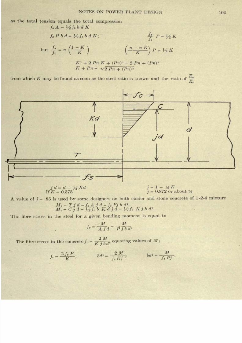
8/20/2019 notes on powerplant.pdf
http://slidepdf.com/reader/full/notes-on-powerplantpdf 115/202
NOTES
ON
POWER
PLANT
DESIGN
as
the
total
tension
equals
the total
compression
f
8
Pbd=y
f
c
bdK;
A
Jc
but
-f
=
Jc
K
n n
K
~K~
P^
1
AK
K
2
+
2
Pn K
+
(Pn)
2
=
2 Pn
+
(Pn)
2
K
+
Pn
=
V2Pn
+
(Pn)
2
pi
from
which K
may
be
found
as soon
as
the
steel
ratio
is
known and the
ratio
of
-^
108
j
d
=
d
-
If
A'
=
0.375
j
=
1
-
y
K
j
=
0.872
or
about
A value of
j
=
.85 is used
by
some
designers
on
both
cinder
and stone
concrete
of
1-2-4
mixture
M
c
=Cjd=
Y
f
c
b
Kdjd=
y
f
c
Kjbd*
The
fibre
stress
in the
steel
for
a
given
bending
moment
is
equal
to
_M_
_M_
'*
A
jd~
Pjbd*
The fibre stress
in the
concrete
f
e
=
equating
values
of
M;
f
2
/*
P
.
;-
K
,
2
M
fcKj
M
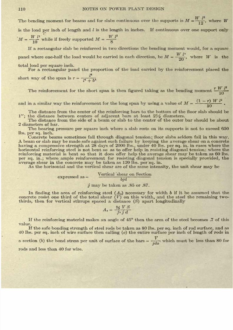
8/20/2019 notes on powerplant.pdf
http://slidepdf.com/reader/full/notes-on-powerplantpdf 116/202
110
NOTES
ON
POWER
PLANT
DESIGN
W
I
2
The
bending
moment
for
beams
and for
slabs continuous
over the
supports
is M
=
where W
L
is
the load
per
inch
of
length
and
/
is
the
length
in inches.
If
continuous
over
one
support
only
W
I
2
'
W
I
2
M
=
while
if
freely supported
M
=
ID
o
If
a
rectangular
slab
be
reinforced
in
two
directions
the
bending
moment
would,
for
a
square
W
/
2
panel
where one-half
the load
would
be carried in
each
direction,
be
M
=
577-,
where
W
is
the
*ni
total
load
per
square
inch.
For
a
rectangular
panel
the
proportion
of
the load carried
by
the
reinforcement
placed
the
Z
4
short
way
of the
span
is
r
=
^ p
r
W I
2
The
reinforcement
for
the
short
span
is
then
figured
taking
as
the
bending
moment
^
(I
r)
W
I
2
and
in
a
similar
way
the
reinforcement
for the
long span by
using
a
value
of M
=
-
^
-
.
The
distance
from the
center of
the
reinforcing
bars to
the
bottom of
the
floor
slab
should be
1 ;
the distance between centers
of
adjacent
bars
at least
2^
diameters.
The distance
from the
side
of
a
beam
or
slab
to the center
of
the
outer
bar
should
be
about
2
diameters of
bar.
The
bearing
pressure per
square
inch where a
slab
rests
on
its
supports
is
not to
exceed
650
Ibs.
per
sq.
inch.
Concrete beams sometimes
fail
through
diagonal
tension;
floor
slabs
seldom
fail in this
way.
A
beam
or slab
may
be made safe
against
such failure
by
keeping
the
average
shear
on a concrete
having
a
compressive
strength
at 28
days
of 2000
Ibs.,
under
40
Ibs.
per
sq.
in. in
cases
where
the
horizontal
reinforcing
steel
is
not
bent
so
as
to
offer
help
in
resisting diagonal
tension:
where
the
reinforcing
material
is
bent
so
that
it does offer
help
the
average
shear
may
be
taken as 60
Ibs.
per sq.
in.;
where
ample
reinforcement
for
resisting diagonal
tension
is
specially
provided,
the
average
shear
in
the concrete
may
be
taken
as 120 Ibs.
per
sq.
in.
As
the horizontal
and
the vertical shear
are
of
the
same
intensity,
the unit shear
may
be
Vertical 'shear on Section
expressed
as
=
bjd
j
may
be
taken as .85
or
.87.
In
finding
the area
of
reinforcing
steel
(A
8
)
necessary
for
width
b
if
it
be assumed that
the
concrete
resist one
third
of
the
total
shear
(V)
on
this
width,
and
the
steel
the
remaining
two-
thirds,
then for vertical
stirrups
spaced
a
distance
(S)
apart longitudinally
If
the
reinforcing
material makes
an
angle
of 45
then the area
of
the steel becomes .7
of this
value.
If the
safe
bonding
strength
of steel rods
be
taken as
80
Ibs.
per sq.
inch
of
rod
surface,
and as
40
Ibs.
per sq.
inch
of
wire
surface
then
calling
(o)
the
entire
surface
per
inch of
length
of rods
in
y
a
section
(6)
the bond
stress
per
unit of surface
of the
bars
=
-
.
,
-
which
must
be
less
than
80 for
jdo
rods
and
less
than
40
for
wire.
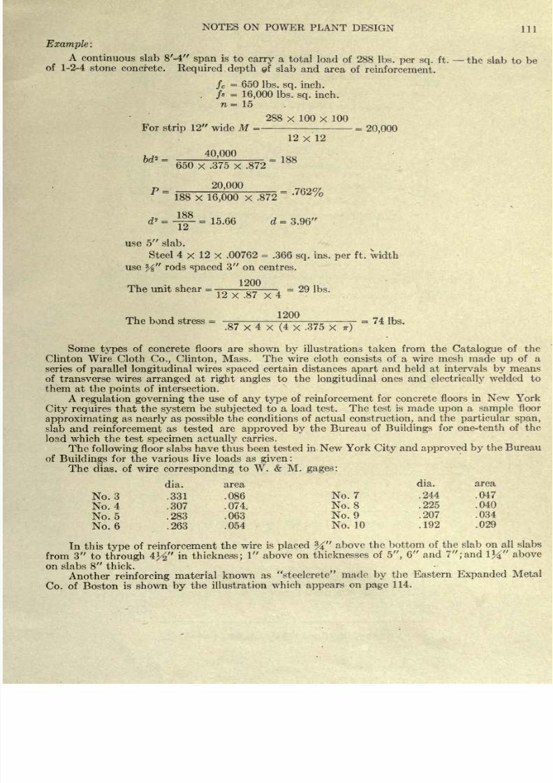
8/20/2019 notes on powerplant.pdf
http://slidepdf.com/reader/full/notes-on-powerplantpdf 117/202
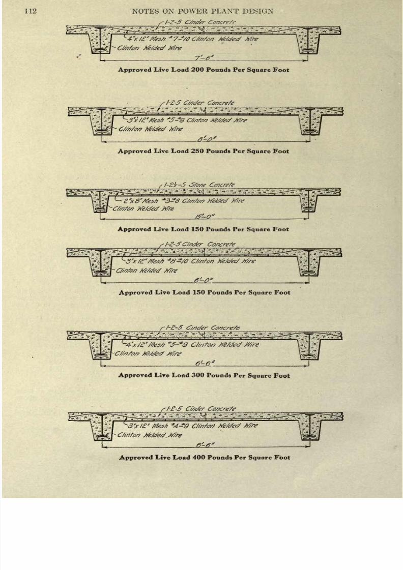
8/20/2019 notes on powerplant.pdf
http://slidepdf.com/reader/full/notes-on-powerplantpdf 118/202
112
NOTES
ON POWER
PLANT
DESIGN
Approved
Live Load
200
Pounds
Per
Square
Foot
fl-Z-5
C/nder
Approved
Live
Load
250 Pounds
Per
Square
Foot
-2?-5
Jfonf Concrete
Mre
We/cfed
ttfre
Approved
Live Load
150
Pounds Per
Square
Foot
_
S
1-2-5
C/nefer
Concrete
Approved
Live Load
150
Pounds Per
Square
Foot
Approved
Live
Load
300
Pounds
Per
Square
Foot
Approved
Live Load
400
Pounds
Per
Square
Foot
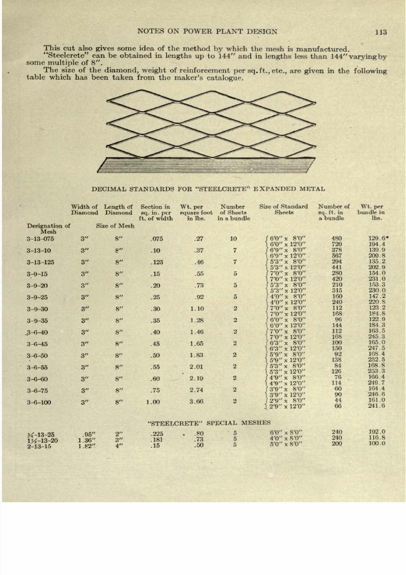
8/20/2019 notes on powerplant.pdf
http://slidepdf.com/reader/full/notes-on-powerplantpdf 119/202
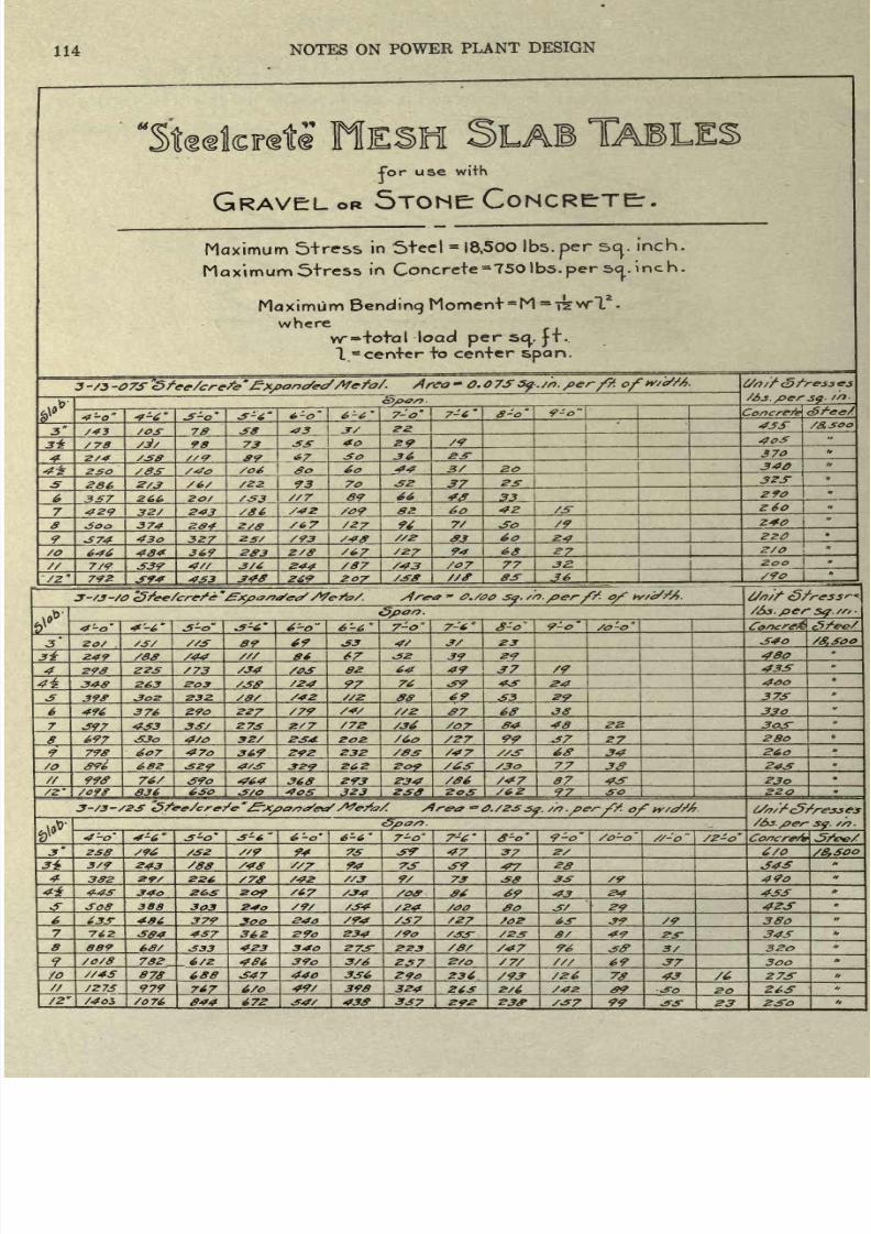
8/20/2019 notes on powerplant.pdf
http://slidepdf.com/reader/full/notes-on-powerplantpdf 120/202
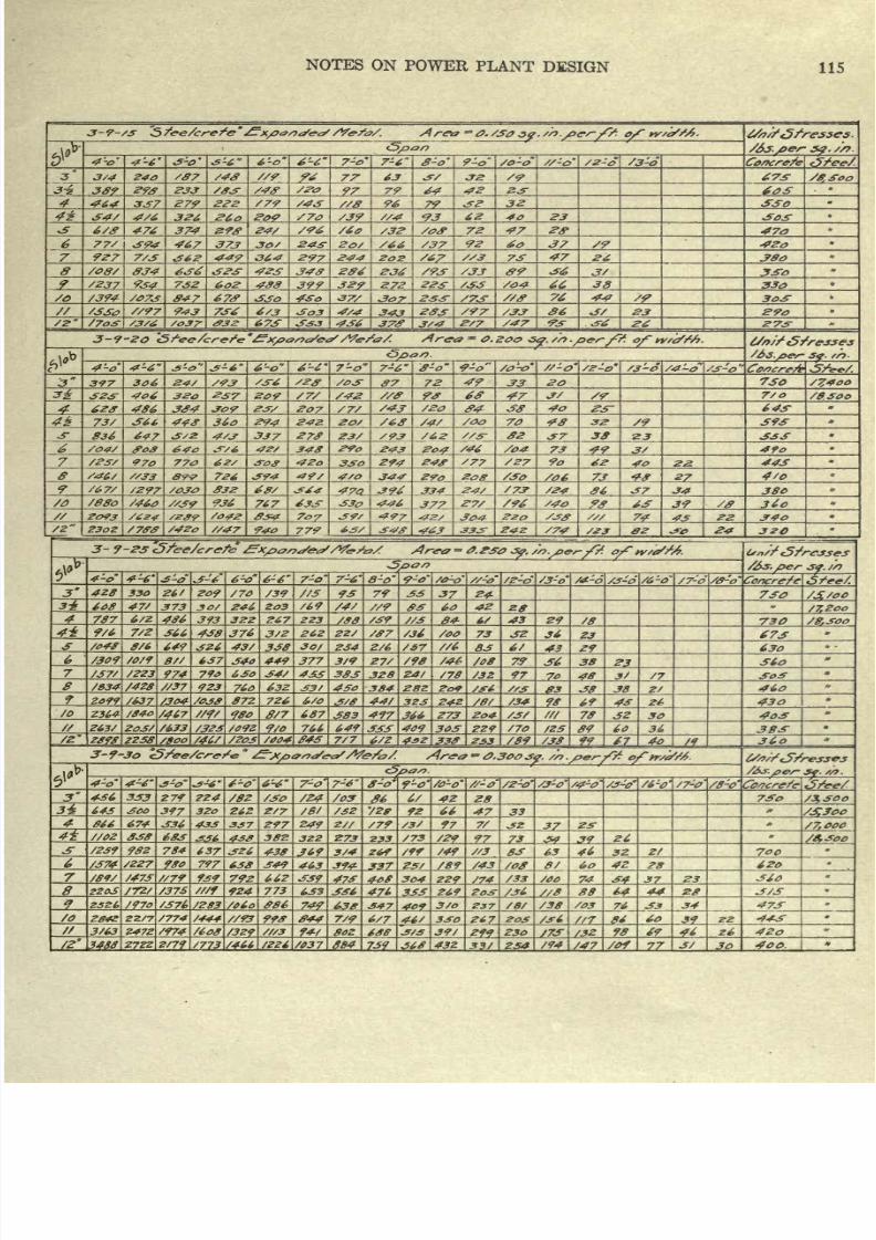
8/20/2019 notes on powerplant.pdf
http://slidepdf.com/reader/full/notes-on-powerplantpdf 121/202
NOTES
ON
POWER
PLANT
DESIGN
115
3-9-/S
Sfee/crefe
?x/>0s)/ft/
S/ffa/.
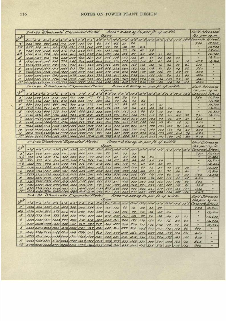
8/20/2019 notes on powerplant.pdf
http://slidepdf.com/reader/full/notes-on-powerplantpdf 122/202
116
NOTES
ON
POWER
PLANT
DESIGN
3-?-33
S/ee/cfefe
-
0.3S0
Jp.
/6s.
/>er
jp.
//}.
6-0
6-6 7-o
7-6
8-0
7-0'
/0-0'
/z-o /3-0 /4-0 /7-o
/fS-0
Concrete
480
372
294
236
/93
92 46
3/
20
3*
642
340
S62
99
72
.52
37
2S
.
900
4*.
908
Z07_
S7_
37A
3/3
263,
Z22.
77
4/
28
/31400
S/66
9/0
726
408 407
343
292
250
/0S
/4o 80
60
44
.V
/6,
9oo
/446 //29
03_
7J.L
430
367
3/S
236 /79
f/
6/
4s
32
22 /8,2oo
/03j
/434
//4g
77S
649
469
403
302
Z3/
/78
/37 /06
a/
6/
44
31
IT
67S
/8.SOO
2203
/723
//2S
78'
48*
2/6 /68
/3o
/oo 76
40
Zl,
6/0
Z?6
20J3
/3/S
774
429 3Z0
ZS4
/33
17
40L
32-
294S
2306
7S8_
6S3
378 292
zzs
/78
/38
7_
57-
3?
320
/o 3320 zs96
2Q7<?
/OOP
833
736
336
427
330
Z3S
9o
4s_
490
3W4
28<?/
23/4
3/83 23SO
/726
/3/3
9S3
620 476
/449
/ZZ9
6*4
326
349
408
289
Z26
/36
/03
7S
3/9
230
04
46o
44o
3-6-40
of
w/t//6.
-so.
4-4
3-0
6-0 6-6'
7-o'
7-6
8-0
9-0'
/o-o
//-o
-o'
/4-o'
/3^>
/6-0'
/7-o'
3
S03
389_
203
/39_
98
70
49
34
23
7S0
//,300
7/3
334
3J6
Z92
Z43 203
77
40 20
/?,
800
9S4
743
S9Z 330
27*
Z36
2.01
/48
83 6Z.
43 32.
Zl
/4.200
.4*.
'*'i 93Z_ 7Ao_
6/9
//_
427
307
Z63
/96
/48
48_
Z4_
/S/7 //8s
948
773
640
4S4
387
/47_
88
17_
37_
S_
/6,8oo
zofo
1070_
88_ 74*
632
34/
467
333
Z//
/66
/30
/02
7_9_ 60_
4S_
32
730 /8,30o
Z3/3
/S78
/289
S96
763
6S3
3-63 427
237
/23
90
76
37
660
2<?38
fZSo
/oso
764
660
SOO
386
Z38
SO
6/0
3318
2638
Z//6
/7Z8
S434
/024
878
738
376
444
348
2/7
/3S
e/
60 S6S
/o
379S
2970
2383
/946 /39 //S4
989
033
649
JO/
393
Z46 /9S
/Zo
t>9
42/8
/Z*
330?
26SZ 2/63
/790
/S/2
//Of
723
33?
439
347
4630
364o
Z92o 2388
/98t
/666
S4/6
/Z/4
/030
79$
6/S
484
383
Z7S
304-
Z/8
Z4Z
/73
/04
7A
493
/SO
fl7
/8-0
404
238
/22
73
37
2jr
7SO
738
S74
370
304
/79
f/ J9
43
30
99/
772
JO/ 4/3
344
290
246 /36
88
66
49
Z4_
/26S
79Z 6*4 J3Z
446
376
27S
206
69
/3.2QQ
J2
38
/4
f
4oo
/23/
004
666
472
4O3 26/
/Zo
93
7Z J4
40
29
J9
2Z&S
/4/7
$08
686
38S
290
/84 /46
7/
/7,8oo
2823
Z2/3
/776
/2Q7\/0/6
S64
74/
64/
480
379 29f
236 /89
93
74
37 70S
/8.3OO
3303
2370 /7oo
/4/S
/o//
069
7S/
372 444
3SO
270
/7f
/42
00_
6
so
2963 2370
/94S
/6/f
/36Z.
99*
06/
40Z
3Zo
ZSTi
/6S
/03
80
4Z3S
334o
?6So
2/94
/ffZ3
74/
2*43 203/
/Z3/
/Of
3
4093\3Z9<
/37<7
//94
J?7-
643
7/Q
433
36Z
447
290_
32S
339
233
26/
Z8f_
/07
/49
9/
36
S
2/0
/04
t50a/7.
4-0
7-o
7-6
8-0
9-o'
//-o'
/3-a
/4-d /6-o
/0z6
800
638
ZS6
2/9
92
70
30
27
750
/2.300
/32o
/030
824
672
46S
393
333
ZAfi
2/6
74
/6Z8
/Z73
/0/9
832
6S9
&SL
490
4/9 Z.7Z
76
Jft
/Z03
7/4
244
/Z2
7
8
9
/0
?A-
3/3/
2433
/973
963
7/7
4*27
33ff
27*
2/7
3660
287o
Z303/a00 /S7o
/323
//27
397
3/<f
20
/67
/3S
4/93
3200
Z643
Z/66
/8o/ /3/
964
739
577
457
296
239
/57
/O/
640
4725
3703
297?
2438
Zoz? /7/O
#33
324.
3Z63\4/ZS
33Z/
ZTZ^
2263
/foe
/627 /39?
/Z//_
9Z9
727
463
304_
?4
65
7fo\434S\36So\Z99/
\249o\Z
/OO
/79o
8o/
33
273
79
43
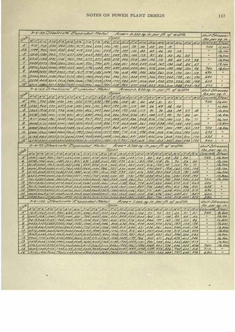
8/20/2019 notes on powerplant.pdf
http://slidepdf.com/reader/full/notes-on-powerplantpdf 123/202
NOTES
ON
POWER
PLANT
DESIGN
117
737 626
444
/36
//O
6f_
730
/a,
4oo
22J8 /73#
/406
?*.
383 303 382
293
/44
32.
/2,/QO
7
3//8
2443
/608
/J37
//26
93?
824.
7/*_ 33Z_
2/6_
/7S_
9o
7/
/3
f
7oo
/760
/433
/266
722L
370
434
36~ 296 242
/6Z
/3Z. /3,/QO
~f/73
406
f
3273 2636
?2Jff
/#39
/6/4 /39/
/2/0
932
734
S87
476
389
320 264
Z/_
/6,3oo
6330 4??3
4020
3303
Z734
23Z7
/493
//34
f*_
Z3/_
Sf3 403
336
280
Z34
74
a
3
3323
4&?ff
70/
377 474
394
334
233: 730
/z
82/0
6460
3203
4273
33~6<9
3O/S 238O
ZZ2?
/&?o
779
642
333
444
37Z
3/3
263
690
90/3
7033
37/3 46?3
39/3
/307
#37
706
333 4/2
346_
24/
ASS
/4
93ZS -77
ZS
6225
3//S
4Z7i
36/3
3o33\
266S
2323
/?<?<?
/42s
//^6
933
77/
64/ 430
379
3/9
/0t3Ji 8J63_
6733_
3333
4623
J0
334J_ 2jf,9
Z3/3_
4973
42/0
3600
3/A
/243_
336
332
347
600
3^2
444
373
4'-o
7-o
/3-0'
/4-0'
/3-
/7-o
/6/3
6S3 373
4/3-
337
269
/6o
73T
37
43
Z/
730
8*600
/?3f/a46
Sff/
749
643
336 4Z3 3Z9
/04
S3
/A/00
34/3
Z6S/
2/S3
909
73?
473
376
2-44
/99
/62
/32
/07_
S6_
//,400
4485\33ZQ
Zg33Z3?3
/933
/636
306
634_
^06
409
334
274
/#7_
/34
/Z^OtL
3673
4463
33?3
Z<?^
/336
634
436
209
/3.80O
697o
3~43o
44/3\3627
JQ3o
ff/3
663
434
3/9
/4,8oo
8363
63S3
33o3
/343
/2Z&
937_
03 663
337
467_ 394_
334^
283
7793
62ff
3/70
43^o
J660
3/32
27/Q 2363 /33S
/439
//79
Soz
67S_
&L
473_
407
346
/3
//478 9o3g
72
SS
S??J
/700
/377
//3/
94o_
666
366
42_
4/3
/7,90o
/4
/2XSS
/0/73
233
67933665
43oo
4//S
336S
3
'//,
24ZC
/923
/36/ /234
/06?
73f_ 646_
332
42f_
74Q
/-S
7333
6/33
3/<?3
4433
383S
3368^ ggg
2o87
/693
973.
7*2
6OO
3/3
7/0
/3//0
//?0o 9600
7900
6603 S6oo 4ff0o
4/33
J63O
282S\
22S-Q
/82S
/So/
/230
/0J0
389
73
643
336
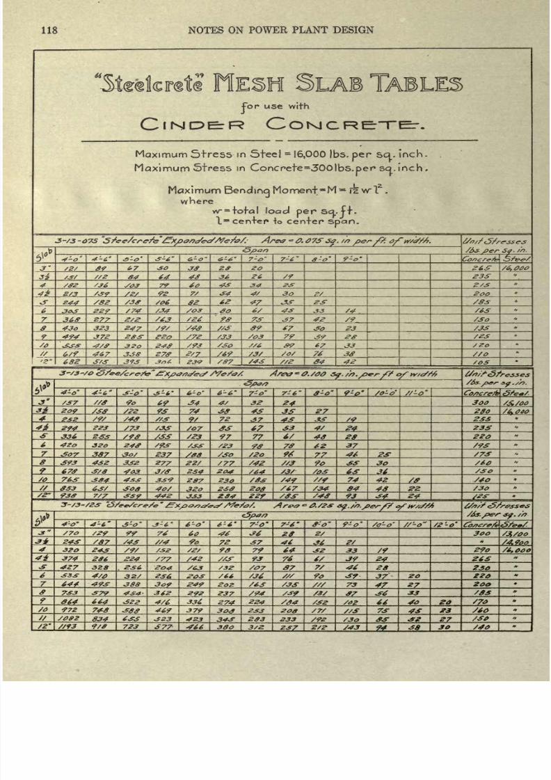
8/20/2019 notes on powerplant.pdf
http://slidepdf.com/reader/full/notes-on-powerplantpdf 124/202
118
NOTES ON
POWER
PLANT DESIGN
For
use
with
Maximum
Stress
in
Steel
=
16,000
)bs.
per
scj..
inch.
Maximupn
Stress
in
Concrete
=30O)bs.
per
so.
inch
.
Maximum
Bending
Moment^M
*
iz
wl
z
.
where
w
=
totcl
load
per
Scj..
ft.
1
st
center*
to
center
span.
3-S3
-075
Area
=
0.
07S
3%.
//?
/><?/
/?.
0/~
if/a?//?.
7-0
7-6
8-0'
9-0-
/6,
040
4
36
26
23S
60
43
Z/3
2/3
92
4/
44
02
62
47
33-
/83
S2?
/74
6/
43
/4
36ff
277
37
42
/9
/30
43^
323
47
09
7
23
372
20
/S3
79
39
/23
S30
J9?_
67
33
/2o
467
338
270
2/7 /69
76
//O
682
393
/87
/43
34
42
4-t,
6-0 6-6
7'o
8-0 9-o
</<?/
/37 //S
_^fL
34
4/ 32
^L.
/A
/^
209
/30
_^L
_2_
_38_
J*- ^3L
Zffo
232
//.*
3-
72 JiS
233
Zf*
223
/07
^Z_
3
4/
23S
336
97
77_
40
.?&-
220
420
320
/23
30_
70
62
37
/9S
*&>7
387
237
/08
/2o
94
77
23-
S73*
4S2
277
22/
/77
/42
90
30
/60
670
403
2S4
204
/64
36
/30
/O
763
339
207
230 /49
74
4Z
^S-
053
32o
230
200
/67
/34
84
48
/30
930
7/7
442
284 229
93
34
24
6-0 6-6
7-0'
7-6 /o'-o
//-o
/2-o'
/70
60
2/
3oo
/87
72
37
46
/4.900
320
98
79 64
33
/9
29o
374 264
224 /77 /42
93
74
6/
24-.
26
427
328
37
7/ 46
28
230
4/0
3Z/
/66
S36
9o
-S7
37
ZO Z20
202
73
*2L
_*7_
7^3
079
_292_
237
/94
_^2L
33
4/6
336
274
224 /S4
/32
66
40
/o
972
7+S
469
379
30,9
233 200
/7S
S/3*
73-
4S
^3
S66
834
323
4Z3
343
203
233
/3o
2-
/2
m
9/8
723
377-
466
300 3/2.
237
2/2
94
38
30
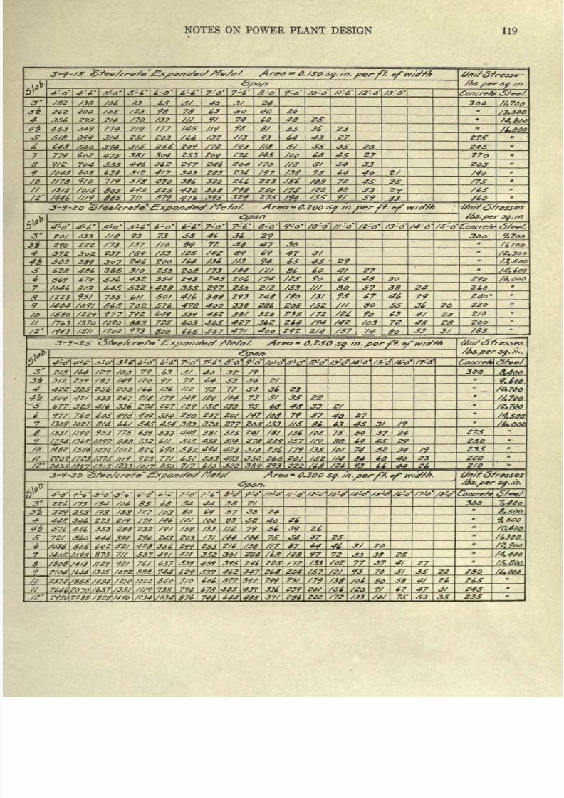
8/20/2019 notes on powerplant.pdf
http://slidepdf.com/reader/full/notes-on-powerplantpdf 125/202
NOTES ON
POWER
PLANT
DESIGN
119
J-9-/3
of
3-6
6-0'
6-6
7-0'
7-6'
-O
/Z-0' /3-0
/82 #3 63
40
24
3oo
/Z3 63 40
24
'3.300
74
60
3+9 Z74
Z/9
/77
/43
40
33
36
/4,800
23
/6.000
399
J/4
/37
93
64
43
27
Z73~
648
3^4
3/3 234 209
/43
ff/
33
33 20
Z43
77V
473
38/
309
2S3
209
'74
/43
43
9/2 333
446
297 246
34
33 205
80S
3/Z
4/7
343
203
234
/97
93
64
40
'90
/o
//78
9/o
7/9
470
386
320
246
2Z3
72
43
/73
^03
443
323
298 /73
/22
82
33
^3-
/63
/Z #03
379
393-
32<9
2.73-
/94
9/
JT9
33
/60
3-9-20
4-o 4-6 3-0
3-6 6-0'
7-6
8-0
/0-o' //-o
/s-o' /3-o'
/4-0
//ff
93
38
46
36
29_
300
9.7oo
2
/73
/37
-47
30
392
302
237
/09
/33
S02
04
69 -47
303
389
246
94
63
4S
29
628
3/0 2^3
Zo8
/73
/44
60
27
867
674
43Z 334
293
243
204,
/74 90
63
43
290
/6.00O
/046
ff/3
22
333 Z97
230
2/Z
/33
So
37
38
24
260
/223
733
&//
348
293
248
/ffo
67
240
/404
7oz
338
286
80
33-
36
20
220
/o
tSffo
/ZZ?
977 792
649
339
432
38/
323 233
S72
/26 90
63
4/
2/0
/763
/37o
833
723
603
303
427
J62
/42
/03
72
48
/ZOZ 973
goo
65
3
7
47/
Z9Z
2/4
/37
, Y4
80
33
3/
-3-9-
4-6
-ff
6-0
7-6
-0 9-0
/0-0*
/4-0'
/-
/6-0'
2/3
3*
3/2
/S7
79
4**
4*^
64_
93
3oo
A400
33
77 33
36
7.4*0
67
/49
7S
3/
313*
677
4/6
336
Z74
Z27 /89
93
68
4<f
S3
/2.700
977 760
490
334 237
Z0/
/47
79
37
27
8/4_
*/
343
434
383
324
277_ 63_ 3/_
/2_
/&000
/33/
//94
933 773
32S
24/
/36
/02
73
34
37 24
273
'092
$8
732
3/3
438
374
/37
80
64 43
29
230
382
494
423
3/4
236
/79
/33
74
34
233
923
77/
63/
333
473_
265
20/
/JZ
//4 #4
60
40_
220
/'
/Z33
&3Q
7/7
6/0
389
?73
Z22
93
26
2/0
3-7-30 <5/&e>/<:r( -/e
,Area 0.300 S0.
6-6
7-6
8-0
/2-0
/3-0~
/4-0'
3
Z26
34
44
33
300
329
/27
84
69
37
3S
A
300
44S
346
273
/2
/2S
/oo
03
38
40.
26
376
446
3S3
/*.
/33
34
26
7Z/
444
243
203
73-
3jL *2L
//.300
flat 642
32/
233
Z/6
87_ 4A.
875
387
4/4
3SZ 30/
1?<L
97
22_
33
3*
/4,440
//2f
637
339_
43?
393
296
/72
/33
/02
77
4/
27
Z/04
/644
^-3/3
888
744
629_
337
462
347
264
204
/37
70
33
22
200
/6.000
/O 7/0
6*6
322
392 299
23/
flo
38
26
938
79^
383
439
2S9_
/36
9/ 67
47__
J/ 243
876 4
644
37/
236
ZZZ
/33
/o/ 73-
33 33
23S
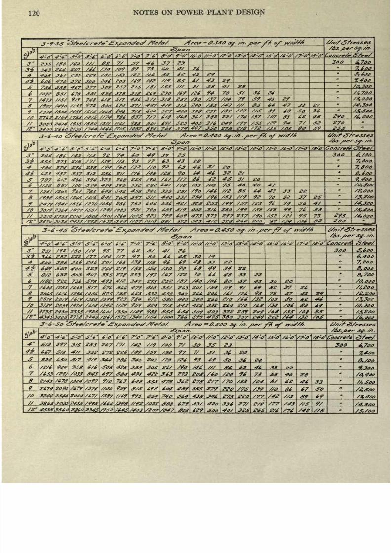
8/20/2019 notes on powerplant.pdf
http://slidepdf.com/reader/full/notes-on-powerplantpdf 126/202
120
NOTES
ON
POWER
PLANT
DESIGN
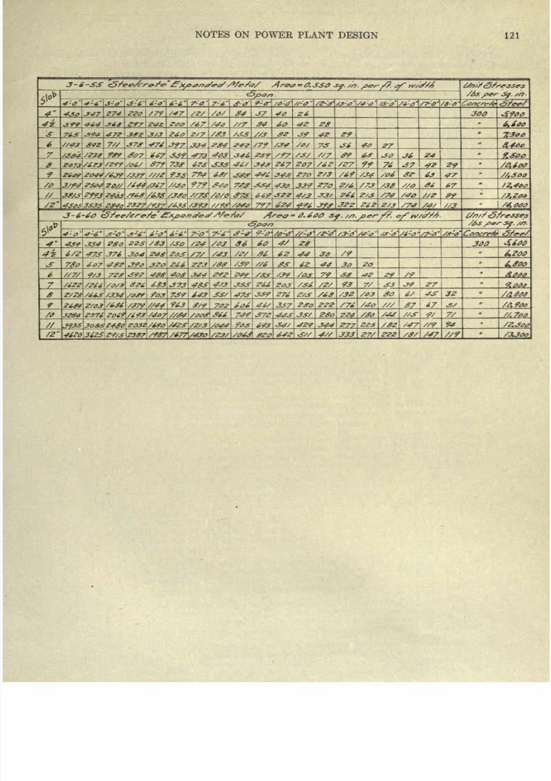
8/20/2019 notes on powerplant.pdf
http://slidepdf.com/reader/full/notes-on-powerplantpdf 127/202
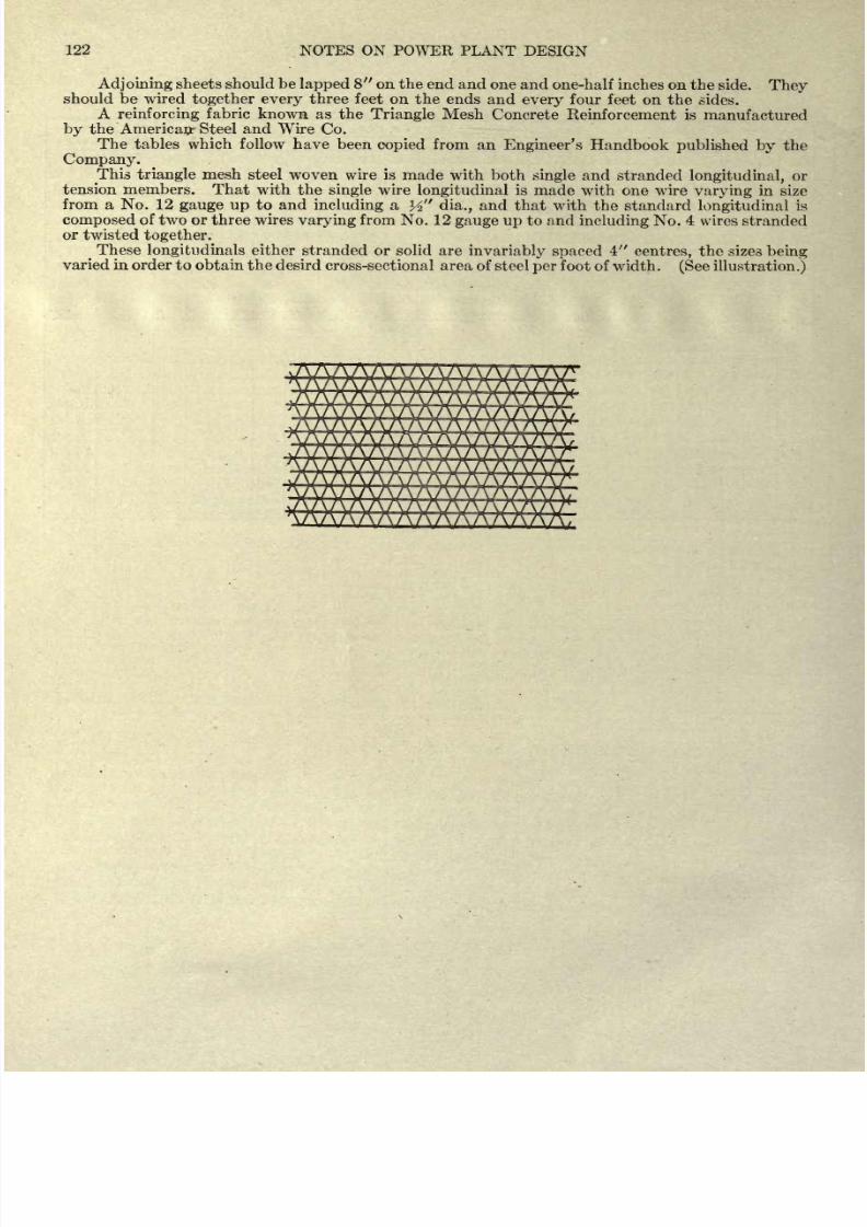
8/20/2019 notes on powerplant.pdf
http://slidepdf.com/reader/full/notes-on-powerplantpdf 128/202
122
NOTES
ON
POWER PLANT
DESIGN
Adjoining
sheets should
be
lapped
8 on the end and
one and
one-half
inches on the
side.
They
should
be
wired
together
every
three
feet on
the
ends
and
every
four
feet on
the
sides.
A
reinforcing
fabric
known
as
the
Triangle
Mesh
Concrete
Reinforcement
is
manufactured
by
the
American- Steel and
Wire
Co.
The tables which follow have been
copied
from an
Engineer's
Handbook
published
by
the
Company.
^This
triangle
mesh steel
woven
wire
is
made
with
both
single
and
stranded
longitudinal,
or
tension
members.
That
with the
single
wire
longitudinal
is
made
with
one
wire
varying
in
size
from
a
No.
12
gauge
up
to
and
including
a
K
dia.,
and
that
with
the
standard
longitudinal
is
composed
of
two
or
three
wires
varying
from
No.
12
gauge
up
to and
including
No.
4
wires
stranded
or
twisted
together.
^
These
longitudinals
either
stranded or solid
are
invariably
spaced
4
centres,
the sizes
being
varied in
order to obtain the
desird
cross-sectional
area of
steel
per
foot
of
width.
(See
illustration.)
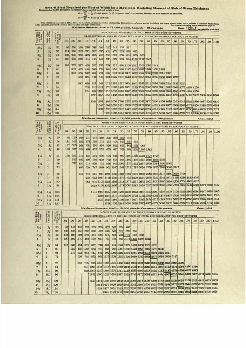
8/20/2019 notes on powerplant.pdf
http://slidepdf.com/reader/full/notes-on-powerplantpdf 129/202
Area of
Steel
Required
per
Fpot
of
Width
for
a
Maximum
Reacting
Moment of
Slab
of
Given
Thickneat.
Corresponding
SAFE
BENDING MOMENT
due
to
applied
load
and
weight
of
looti
'
M
^jj-
=
Jjj
X
Load
pet K.
ft.
X
(length
el
.pan)*
=
Bending
Moment
for allb
supported
oa
two (UN.
M
^
^
=
Bending
Moment
,
The
Maximum Allowable Fiber Stress
in
the
steel
governs
the values of
Relating
Moments
siren
below
ai.d
to
the
left of the heirr
zirzar
line-
the M
ixlmom
Allowable
Plkr M_
In
the concrete
governs
the values above
and
to the
right
of
this line.
Po,
example
showing
DM
of
tablet see
page
w
Maximum
Streaaeas Steel
=
18.OOO
pound., Concrete
=
65O
pound.
Cm
Total
Thlck-
n
,nche.
]
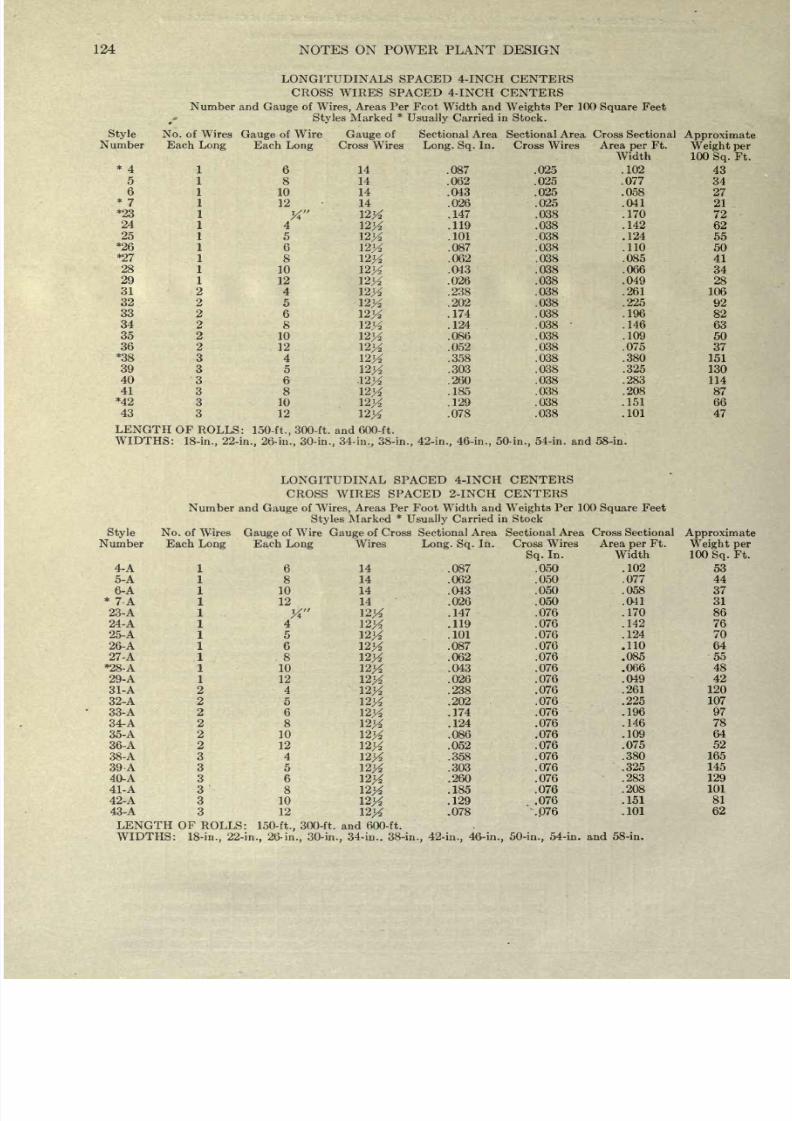
8/20/2019 notes on powerplant.pdf
http://slidepdf.com/reader/full/notes-on-powerplantpdf 130/202
124
NOTES
ON
POWER
PLANT
DESIGN
LONGITUDINALS
SPACED 4-INCH
CENTERS
CROSS
WIRES
SPACED
4-
INCH
CENTERS
Number and
Gauge
of
Wires,
Areas Per
Fcot
Width
and
Weights
Per
100
Square
Feet
t
'
Styles
Marked
*
Usually
Carried
in
Stock.
Style
No.
of
Wires
Gauge
of
Wire
Gauge
of
Sectional
Area Sectional Area
Cross
Sectional
Approximate
Number
Each
Long
Each
Long
Cross
Wires
Long.
Sq.
In.
Cross
Wires
Area
per
Ft.
Weight
per
Width
100
Sq.
Ft.
*4
1
6
14
.087 .025
.102
43
51
8
14
.062 .025
.077
34
61
10
14
.043
.025
.058
27
*
7 1
12
14 .026
.025
.041
21
*23
1
X
12tf
.147 .038 .170
72
24
1
4
12^
.119
.038 .142
62
25
1
5
12#
.101 .038 .124
55
*26
1
6
12#
.087 .038
.110
50
*27
1
8
12#
.062 .038
.085
41
28 1
10
12#
.043
.038 .066
34
29
1
12
12#
.026 .038 .049
28
31
2
4
12K
-238
.038
.261
106
32
2
5
12#
.202 .038
.225
92
33
2
6
12K
-174
.038
.196
82
34
2
8
12K
-124
.038
.146
63
35
2
10
12K
-086
.038 .109
50
36 2
12
12#
.052 .038
.075
37
*38 3
4
12#
.358 .038
.380
151
39
3
5
12#
.303
.038
.325
130
40
3
6
12#
.260
.038 .283
114
41
3
8
l2)/
.185 .038
.208
87
*42
3
10
12#
.129
.038 .151 66
43
3
12
123^
.078
.038
.101
47
LENGTH
OF ROLLS:
150-ft.,
300-ft. and 600-ft.
WIDTHS:
18-in.,
22-in.,
26-
in.,
30-in., 34-in., 38-in., 42-in.,
46-in.,
50-in.,
54-in. and
58-in.
LONGITUDINAL
SPACED 4-INCH CENTERS
CROSS WIRES SPACED
2-INCH
CENTERS
Number
and
Gauge
of
Wires,
Areas
Per
Foot
Width and
Weights
Per 100
Square
Feet
Styles
Marked
*
Usually Carried
in
Stock
Style
No
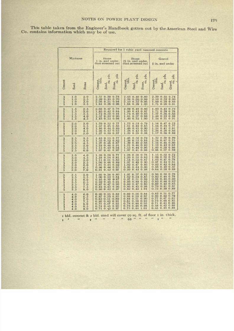
8/20/2019 notes on powerplant.pdf
http://slidepdf.com/reader/full/notes-on-powerplantpdf 131/202
NOTES
ON
POWER
PLANT
DESIGN
12<>
This
table
taken
from
the
Engineer's
Handbook
gotten
out
by
the
American
Steel
and
Wire
Co. contains
information
which
may
be
of
use.
Mixtures
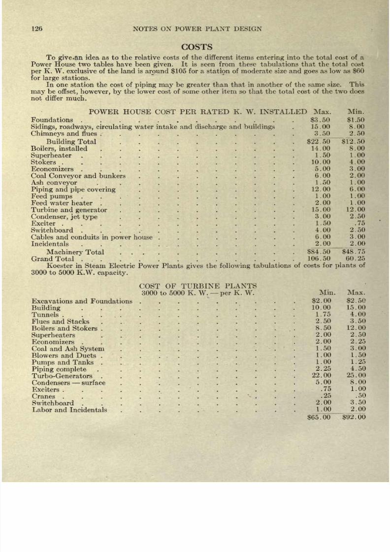
8/20/2019 notes on powerplant.pdf
http://slidepdf.com/reader/full/notes-on-powerplantpdf 132/202
126
NOTES
ON POWER PLANT DESIGN
COSTS
To
give.an
idea as to
the
relative
costs of
the
different items
entering
into the total
cost
of
a
Power
House
two tables have been
given.
It
is
seen from these tabulations
that the total
cost
per
K. W. exclusive
of
the
land is
around
$105
for
a
stati9n
of moderate
size and
goes
as
low
as
$60
for
large
stations.
In
one
station
the
cost
of
piping
may
be
greater
than
that
in
another
of
the
same
size.
This
may
be
offset,
however, by
the
lower
cost of some other
item
so that the total cost
of
the
two
does
not
differ
much.
POWER HOUSE
COST
PER RATED
K.
W.
INSTALLED Max.
Min.
Foundations
. .
....
.
$3.50
$1.50
Sidings,
roadways,
circulating
water intake
and
discharge
and
buildings
.
15.00 8.00
Chimneys
and flues
...........
3.50
2.50
Building
Total
$2~2750
$12.50
Boilers,
installed
14.00
8.00
Superheater
1.50
1.00
Stokers
10.00
4.00
Economizers
.
.
. .
. .
,.
. .
. .
.
5.00
3.00
Coal
Conveyor
and
bunkers . .
. . . .
. . .
6
.
00
2
.
00
Ash
conveyor
.
.
.
.
.
.
.
. . .
.
1
.
50
1
. 00
Piping
and
pipe
covering
.
. . .
. .
. . .
12 .
00
6
.
00
Feedpumps
1.00
1.00
Feed
water
heater
2.00
1.00
Turbine and
generator
15.00
12.00
Condenser,
jet
type
.
. .
.
.
.
.
.
.
.
3.00
2.50
Exciter
1.50 .75
Switchboard
.
. .
4.00
2.50
Cables
and
conduits
in
power
house .
.
. .
.
. . .
6
. 00
3
.
00
Incidentals
2.00
2.00
Machinery
Total
...
....
$84.50
$48.75
Grand
Total
....
...
106.50 60.25
Koester
in
Steam Electric
Power
Plants
gives
the
following
tabulations
of
costs for
plants
of
3000
to 5000
K.W.
capacity.
COST OF
TURBINE
PLANTS
3000
to 5000 K. W.
per
K.
W.
Min.
Max.
Excavations and
Foundations
.
.
.
.
. .
.
.
.
$2
.
00
$2
.
50
Building
.
.
10.00
15.00
Tunnels.
.
...
.....
1.75
4.00
Flues and
Stacks
2.50
3.50
Boilers and
Stokers
8.50
12.00
Superheaters
2.00 2.50
Economizers
2.00
2.25
Coal
and
Ash
System
1.50
3.00
Blowers
and
Ducts
.
.
.
1 .
00
1
.
50
Pumps
and
Tanks
1 .
00
Piping
complete
2
.
25
4 .
50
Turbo-Generators
Condensers
surface
.
.
. . .
. .
.
.
.
5
.
00
8
. 00
Exciters
.75
1.00
Cranes
.25
.50
Switchboard
Labor
and
Incidentals
. .
. .
.
.
.
. .
1.00
_2_.
00
$65.00
$92.00
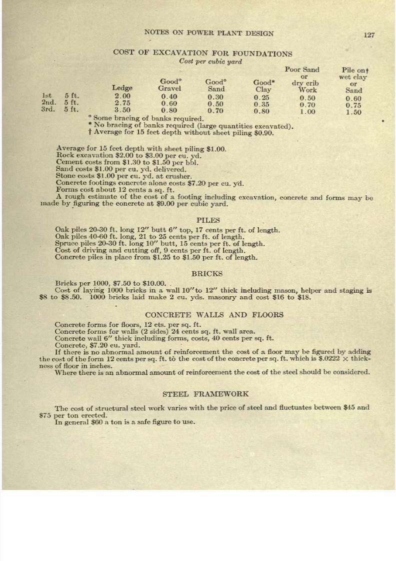
8/20/2019 notes on powerplant.pdf
http://slidepdf.com/reader/full/notes-on-powerplantpdf 133/202
NOTES
ON
POWER
PLANT
DESIGN
127
COST OF
EXCAVATION
FOR
FOUNDATIONS
Cost
per
cubic
yard
Poor
Sand
Pile
onf
or
wet
clay
Good
Good
Good*
dry
crib
or
'
Ledge
Gravel
Sand
Clay
Work
Sand
1st
5ft.
2.00
0.40
0.30
0.25
0.50
060
2n
f
5ft.
2.75
0.60
0.50
0.35
0.70
0*75
3-50
0.80
0.70
0.80
1.00
1.5Q
Some
bracing
of
banks
required.
*
No
bracing
of
banks
required
(large
quantities
excavated),
t
Average
for
15
feet
depth
without
sheet
piling
$0.90.
Average
for
15
feet
depth
with
sheet
piling
$1.00.
Rock
excavation
$2.00
to
$3.00
per
cu.
yd.
Cement costs
from
$1.30
to
$1.50
per
bbl.
Sand
costs
$1.00
per
cu.
yd.
delivered.
Stone
costs
$1
.00
per
cu.
yd.
at
crusher.
Concrete
footings
concrete
alone
costs
$7.20
per
cu.
yd.
Forms cost
about
12
cents
a
sq.
ft.
A
rough
estimate
of
the
cost
of a
footing
including
excavation,
concrete and
forms
may
be
made
by
figuring
the
concrete
at
$9.00
per
cubic
yard.
PILES
Oak
piles
20-30
ft.
long
12
butt
6
top,
17
cents
per
ft.
of
length.
Oak
piles
40-60
ft.
long,
21
to
25
cents
per
ft.
of
length.
Spruce
piles
20-30 ft.
long
10
butt,
15 cents
per
ft. of
length.
Cost
of
driving
and
cutting
off,
9
cents
per
ft. of
length.
Concrete
piles
in
place
from
$1.25
to
$1.50
per
ft.
of
length.
BRICKS
Bricks
per 1000,
$7.50
to
$10.00.
.
Cost of
laying
1000
bricks
in
a
wall
10 to
12
thick
including
mason,
helper
and
staging
is
$8
to
$8.50.
1000 bricks
laid
make
2
cu.
yds.
masonry
and
cost
$16
to
$18.
CONCRETE
WALLS AND
FLOORS
Concrete forms
for
floors,
12
cts.
per sq.
ft.
Concrete
forms
for
walls
(2
sides)
24
cents
sq.
ft.
wall area.
Concrete
wall
6
thick
including
forms,
costs,
40 cents
per
sq.
ft.
Concrete, $7.20
cu.
yard.
If
there is
no
abnormal
amount
of reinforcement
the
cost of
a
floor
may
be
figured by
adding
the cost
of
the form
12 cents
per sq.
ft.
to the
cost
of the concrete
per
sq.
ft.
which
is
$.0222
x
thick-
ness of floor
in
inches.
Where
there
is an
abnormal amount
of
reinforcement
the
cost
of
the
steel
should
be
considered.
STEEL
FRAMEWORK
The
cost
of
structural
steel
work
varies
with
the
price
of
steel
and
fluctuates
between
$45
and
$75
per
ton
erected.
In
general
$60
a
ton
is a safe
figure
to
use.
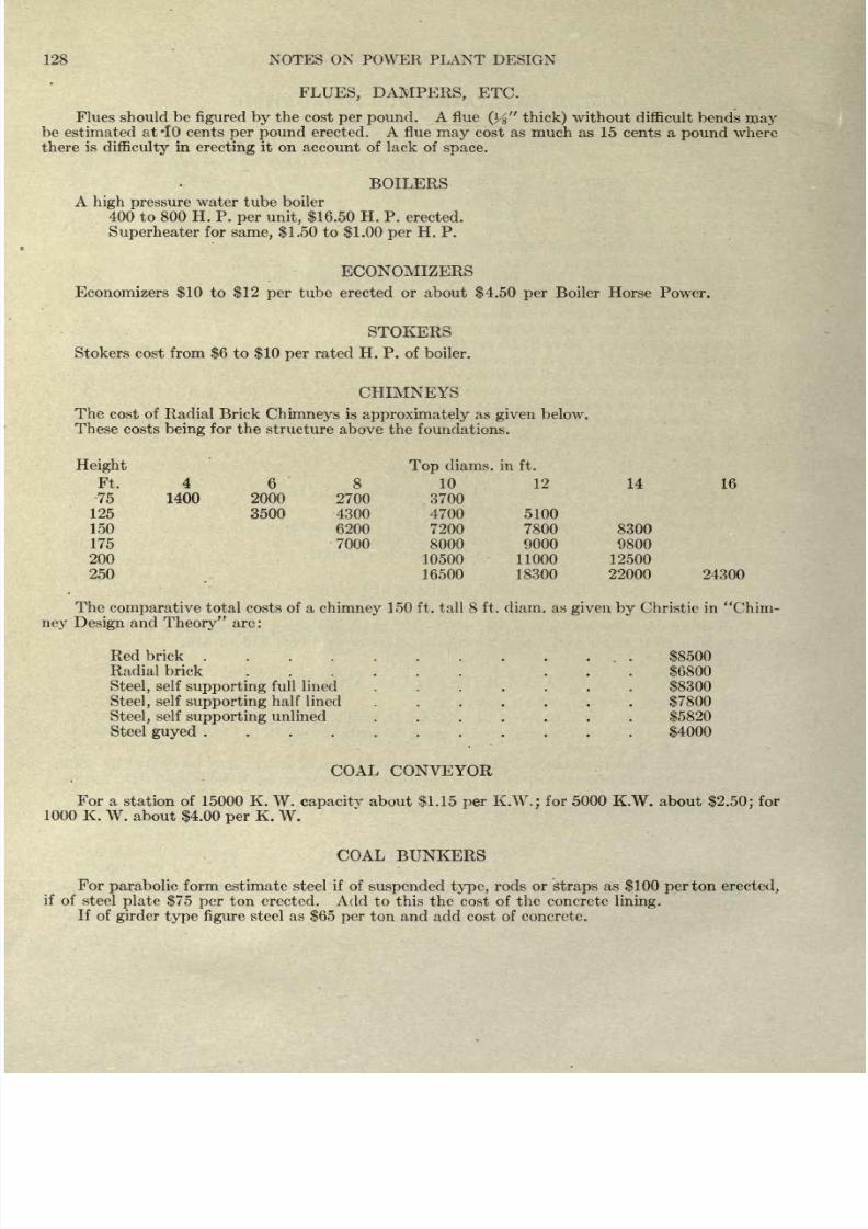
8/20/2019 notes on powerplant.pdf
http://slidepdf.com/reader/full/notes-on-powerplantpdf 134/202
128
NOTES ON POWER PLANT
DESIGN
FLUES, DAMPERS,
ETC.
Flues
should
be
figured
by
the cost
per
pound.
A flue
(y% thick)
without
difficult bends
may
be estimated
at
10 cents
per
pound
erected.
A
flue
may
cost
as
much
as
15 cents
a
pound
where
there
is
difficulty
in
erecting
it
on
account of
lack
of
space.
BOILERS
A
high
pressure
water
tube boiler
400
to
800
H. P.
per unit,
$16.50
H. P.
erected.
Superheater
for
same,
$1.50
to
$1.00
per
H.
P.
ECONOMIZERS
Economizers
$10
to
$12
per
tube
erected or
about
$4.50
per
Boiler
Horse
Power.
STOKERS
Stokers
cost
from
$6
to
$10
per
rated
H.
P.
of
boiler.
CHIMNEYS
The
cost
of
Radial Brick
Chimneys
is
approximately
as
given
below.
These
costs
being
for
the
structure
above
the foundations.
Height
Top
diams.
in
ft.
Ft.
4
6
8
10 12
14 16
75 1400
125
150
175
200
250 16500 18300
22000 24300
The
comparative
total
costs
of
a
chimney
150
ft.
tall
8 ft.
diam.
as
given
by
Christie
in
Chim-
ney
Design
and
Theory
are:
Redbrick
...
$8500
Radial
brick
...... ...
$6800
Steel,
self
supporting
full lined
.......
$8300
Steel,
self
supporting
half
lined
.......
$7800
Steel,
self
supporting
unlined
.......
$5820
Steel
guyed
$4000
COAL
CONVEYOR
For
a
station
of 15000 K.
W.
capacity
about
$1.15
per
K.W.;
for 5000 K.W.
about
$2.50;
for
1000
K.
W.
about
$4.00
per
K.
W.
COAL
BUNKERS
For
parabolic
form
estimate
steel
if
of
suspended type,
rods
or
straps
as
$100
per
ton
erected,
if
of
steel
plate
$75
per
ton
erected.
Add
to
this the cost
of
the
concrete
lining.
If
of
girder
type
figure
steel as
$65
per
ton
and add cost
of
concrete.
8
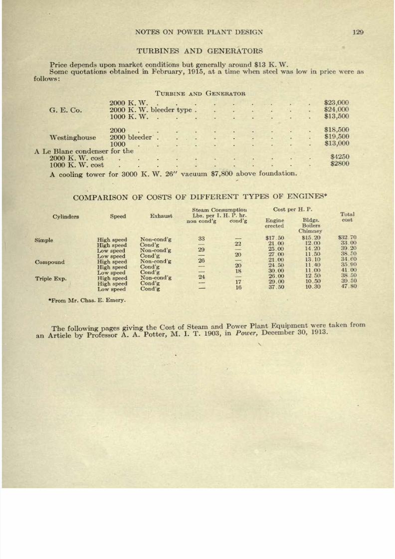
8/20/2019 notes on powerplant.pdf
http://slidepdf.com/reader/full/notes-on-powerplantpdf 135/202
NOTES ON POWER PLANT
DESIGN
129
TURBINES AND
GENERATORS
Price
depends
upon
market
conditions
but
generally
around
$13
K.
W.
Some
quotations
obtained
in
February, 1915,
at
a time when steel was low in
price
were
as
follows
:
G.
E.
Co.
TURBINE
AND
GENERATOR
2000
K.W
2000
K.
W.
bleeder
type
.
1000
K.
W.
2000
.
Westinghouse
2000
bleeder
1000
.
A
Le
Blanc
condenser
for
the
2000 K.
W. cost
1000
K.
W.
cost
$23,000
$24,000
$13,500
$18,500
$19,500
$13,000
$4250
S2SOO
A
cooling
tower
for
3000
K.
W.
26
vacuum
$7,800
above
foundation.
COMPARISON
OF
COSTS
OF
DIFFERENT
TYPES
OF
ENGINES*
Cylinders
Speed
Exhaust
Steam
Consumption
Lbs.
per
I.
H.
P.
hr.
non
cond'g
cond'g
Cost
per
H.
P.
Simple
Compound
Triple
Exp.
High
speed
High
speed
Low
speed
Low
speed
High
speed
High
speed
Low
speed
High
speed
High
speed
Low
speed
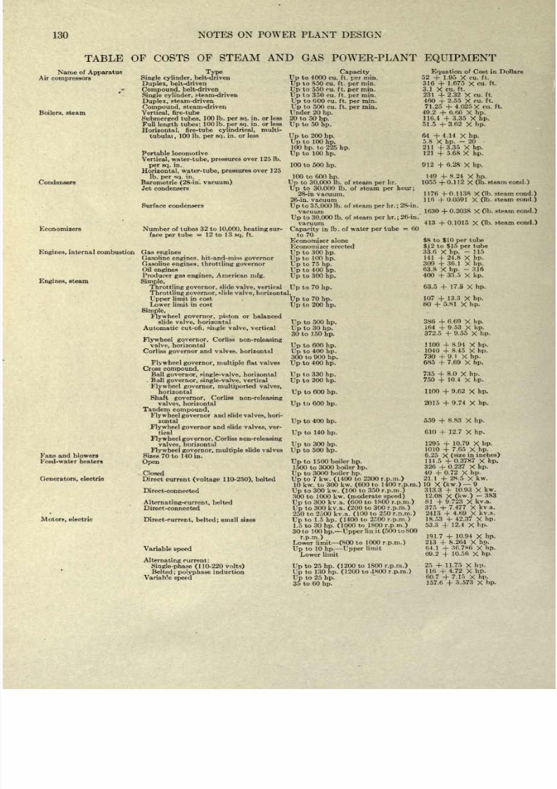
8/20/2019 notes on powerplant.pdf
http://slidepdf.com/reader/full/notes-on-powerplantpdf 136/202
130
NOTES
ON
POWER
PLANT DESIGN
TABLE
OF
COSTS
OF
STEAM
AND
GAS
POWER-PLANT
EQUIPMENT
Name
of
Apparatus
Air
compressors
Boilers,
steam
Condensers
Economizers
Type
Single
cylinder,
belt-driven
Duplex,
belt-driven
Compound,
belt-driven
Single
cylinder,
^team-driven
Duplex,
steam-driven
Compound,
steam-driven
Vertical,
fire-tube
Submerged
tubes,
100
Ib.
per sq.
in. or less
Full
length
tubes:
100
Ib.
per
sq.
in. or less
Horizontal,
fire-tube
cylindrical,
multi-
tubulai,
100
Ib.
per
sq.
in. or
less
Portable locomotive
Vertical, water-tube,
pressures
over
125
Ib.
per
sq.
in.
Horizontal, water-tube,
pressures
over
125
Ib.
per
sq.
in.
Barometric
(28-in.
vacuum)
Jet
condensers
Surface
condensers
Number
of tubes 32
to
10,000, heating
sur-
face
per
tube
=
12 to
13
sq.
ft.
Engines,
internal
combustion Gas
engines
Gasoline
engines,
hit-and-miss
governor
Gasoline
engines, throttling governor
Oil
engines
Up
to 400
hp.
Producer
gas
engines,
American
mfg.
Up
to 300
hp.
Engines,
steam
Simple,
Throttling
governor,
slide
valve,
vertical
Up
to
70
hp.
Capacity
Up
to
4000 cu.
ft.
per
min.
Up
to
850
cu.
ft.
per
min.
Up
to
550 cu.
ft.
per
min.
Up
to
350 cu. ft.
per
min.
Up
to
600
cu.
ft.
per
min.
Up
to
500
cu. ft.
per
min.
Under 20
hp.
20
to
50
hp.
Up
to
50
hp.
Up
to
200
hp.
Up
to 100
hp.
100
hp.
to
225
hp.
Up
to 100
hp.
100 to 500
hp.
100
to 600
hp.
Up
to
30,000
Ib. of steam
per
hr.
Up
to
30,000
Ib. of
steam
per
hour;
28-in
vacuum.
26-in.
vacuum
Up
to
35,000
Ib.
of steam
per
hr.
;
28-in.
vacuum
Up
to
30.000
Ib. of steam
per
hr.;
26-in.
vacuum
Capacity
in
Ib. of water
per
tube
=
60
to
70
Economizer alone
Economizer
erected
Up
to
300
hp.
Up
to 100
hp.
Up
to
75
hp.
Equation
of
Cost in Dollars
52
+
1.95
X
cu.
ft.
316
+
1.675
X
cu.
ft.
3.1
X
cu.
ft.
231
+
2.32
X
cu.
ft.
460
+
2.55
X
cu. ft.
71.25
+
4.025
X
cu. ft.
49.2
+
6.66
X
hp.
116.4
+
3.35
X
hp.
51.5
+
3.62
X
hp.
64
+
4.14
X
hp.
5.8
X
hp.
-
20
211
+3.35
X
hp.
121
+
5.68
X
hp.
912
+
6.28
X
hp.
149
+
8.24
X
hp.
1055
+
0.112
X
(Ib.
steam
cond.)
1176
+
0.1138
X
(Ib.
steam
cond.)
116
+
0.0591
X
(Ib.
steam
cond.)
1630
+
0.2038
X Ob.
steam
cond.)
413
+
0.1015
X
(Ib.
steam
cond.)
Throttling governor,
slide
valve, horizontal,
Fans and blowers
Feed-water
heaters
Generators,
electric
Motors,
electric
Upper
limjt
in cost
Lower
limit
in
cost
Simple,
Flywheel
governor,
piston
or
balanced
slide
valve,
horizontal
Automatic
cut-ofi,
single
valve,
vertical
Flywheel
governor,
Corliss
non-releasing
valve,
horizontal
Corliss
governor
and valves,
horizontal
Flywheel governor,
multiple
flat
valves
Cross
compound,
Ball
governor, single-valve,
horizontal
.
Ball
governor, single-valve,
vertical
Flywheel governor,
multiported
valves,
horizontal
Shaft
governor,
Corliss
non-releasing
valves,
horizontal
Tandem
compound,
Flywheel
governor
and
slide
valves,
hori-
zontal
Flywheel governor
and slide
valves,
ver-
tical
Flywheel
governor,
Corliss
non-releasing
valves,
horizontal
Flywheel
governor,
multiple
slide valves
Sizes
70
to
140
in.
Open
Closed
Direct current
(voltage
1
10-250),
belted
Direct-connected
Alternating-current,
belted
Direct -connected
Direct-current, belted;
smzll sizes
Variable
speed
Alternating
current:
Single-phase
(110-220
volts)
Belted
;
polyphase
induction
Variable
speed
Up
to
70
hp.
Up
to
200
hp.
Up
to 500
hp.
Up
to 30
hp.
30
to
150
hp.
Up
to 600
hp.
Up
to
400
hp.
300 to 900
hp.
Up
to 400
hp.
Up
to
330
hp.
Up
to
200
hp.
Up
to
600
hp.
Up
to
600
hp.
Up
to
400
hp.
Up
to
140
hp.
Up
to 300
hp.
Up
to 500
hp.
Up
to 1500
boiler
hp.
1500 to
3000
boiler
hp.
Up
to
3000
boiler
hp.
Up
to 7
kw.
(1400
to 2300
r.p.m.)
$8
to
$10
per
tube
$J2
to
$15
per tube
33.6
X
hp.
-
115
141
+
24.8
X
hp.
309
+36.1
X
hp.
63.8
X
hp.
-
316
400
+
33.5
X
kp.
63.5
+
17.5
X
hp.
107
+
13.3
X
hp.
80
+
5.81
X
hp.
386
+
6.69
X
hp.
164
+
9.53
X
hp.
372.5
+
9.55
X
hp.
1100
+
8.94
X
hp.
1040
+
8.45
X
hp.
730
+
9.1
X
hp.
685
+
7.69
X
hp.
735
+
8.0
X
hp.
750
+
10.4
X
hp.
1100
+
9.62
X
hp.
2015
+
9.74
X
hp.
559
+
8.83
X
hp.
610
+
12.7
X
hp.
1295
+
10.79
X
hp.
1010
+
7.65
X
hp.
6.25
X
(size
in
inches)
114.5
+
0.3787
X
hp.
326
+
0.237
X
hp.
40
+
0.72
X
hp.
21.1
+
28.5
X
kw.
10
kw.
to
300 kw.
(600
to
1400
r.p.m.)
10
X
(kw.)
9
Up
to
300
kw.
(100
to
350
r.p.m.)
300 to
1000
kw.
(moderate
speed)
Up
to 300
kv.a.
(600
to
1800
r.p.m.)
Up
to
300
kv.a.
(200
to 300
r.p.m.)
250
to 2500
kv.a.
(100
to 250
r.p.m.)
Up
to
1.5
hp.
(1400
to
2f;00
r.p.m.)
1.5 to
30
hp.
(1000
to
1800
r.p.m.)
30
to 100
hp.
Upper
lin.it
(500
to 800
r.p.m.)
Lower
limit
(800
to
1000
r.p.m.)
Up
to
10
hp.
Upper
limit
Lower
limit
Up
to
25
hp.
(1200
to
1800
r.p.m.)
Up
to 130
hp.
(1200
to -1800
r.p.m.)
Up
to
25
hp.
35
to
60
hp.
313.3
+
10.93
X
kw.
12.08
X
(kw.)
-
383
81
+
9.723
X
kv.a.
375
+
7.477
X
kv a.
2413
+
4.69
X
kv.a.
18.53
+
42.37
X
hp.
53.3
+
12.4
X
hp.
191.7
+
10.94
X
hp.
213
+
8.264
X
hp.
64.1
+
36.7S6
X
hp.
69.2
+
10.56
X
hp.
25
+
11.75
X
hp.
116
+
4.72
X
hp.
60.7
+
7.15
X
hp.
157.6
+
3.573
X
hp.
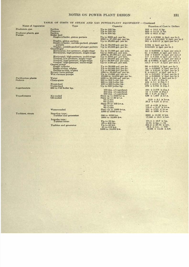
8/20/2019 notes on powerplant.pdf
http://slidepdf.com/reader/full/notes-on-powerplantpdf 137/202
NOTES ON
POWER
PLANT
DESIGN
131
TABLE
OF COSTS OF
STEAM
AND GAS
Name
of
Apparatus
Producers,
gas
Producer
plants, gaa
Pumps
Purification
plants
Stokers
Superheaters
Transformers
Turbines,
steam
Type
Suction
Pressure
Suction
Boiler
feed
Single-cvlinder,
piston
pattern
Duplex,
piston
pattern
Single-cylinder,
outide-packed, plunger
pattern
Duplex,
outside-packed
plunger
pattern
Centrifugal
Horizontal,
low-pressure,
single-stage
Horizontal,
high-pressure, single-stage
Horizontal,
high-pressure, multi-stage
Vertical,
low-pressure,
single-stage
Vertical,
high-pressure,
single-stage
Vertical,
high-pressure,
multi-stage
Geared
power
Single
cylinder
Single-acting,
triplex
Double-acting,
triplex
Rotary
force
pumps
Wet
vacuum
pumps
Water
Chain-grate
Front-feed
Under-feed
200 to
750
boiler
hp.
Air-cooled
Oil-cooled
Water-cooled
Reaction
type:
Turbine
and
generator
Impulse
type
:
Turbine alone
Turbine
and
generator
POWER-PLANT
EQUIPMENT
Capacity
Up
to
300
hp.
Up
to
300
hp.
Up
to
200
hp.
Up
to 6000
gal.
per
hr.
6000 to
27,000
gal.
per
hr.
Up
to
29,000
gal.
per
hr.
Up
to
24,000
gal.
per
hr.
Up
to
49,000
gal.
per
hr.
Up
to
14,000
gal.
per
min.
Up
to
5000
gal.
per
min.
5000 to
20,000
gal.
per
min.
Up
to
2200
gal.
per
min.
Up
to
20,000
gal.
per
min.
Up
to
20.000
gal.
per
min.
Up
to 1100
gal.
per
min.
Up
to
20,000
gal.
per
br.
Up
to
83,000
gal.
per
hr.
Up
to
89,000
gal.
per
hr.
1200 to
20.000
gal. per
hr.
Up
to
13,000
gal.
per
hr.
13,000
to
50,000
gal.
per
hr.
1000
to
20.000
gal.
per
hr.
100 to
300
b
oiler
hp.
300
to
500
boiler
hp.
100
to
660 boiler
hp.
Up
to
600 boiler
hp.
100
detc.
of
superheat
200
deg.
of
superheat
300
deg.
of
superheat
Sizea
up
to 3000
kv.a
Sizes
up
to
30
kv.a.
25
cycles
60
cycles
Sizes
30
to
100
kv.a.
25
cycles
60
cycles
Sizea
up
to 1000
kv.a.
1000
to 3000
kv.a.
500
to 5000
kw.
5000
to
10,000
kw.
Up
to
50
hp.
50 to 400
hp.
Up
to 40 kw.
25 to
350
kw.
1000 to
10,000
kw.
Continued
Equation
of
Cost
in Dollars
252
+
14.2
X
hp.
860
+
15.15
X
hp.
570
+
46.5
X
hp.
17.8
+
0.2586
X
(gal.
per
hr.)
106.8
+
0.011045
X
(gal.
per
hr.)
585
+
0.0115
X
(gal.
per
hr.)
0.034
X
(gal.
per
hr.)
0.042125
X(gal.
per
hr.)
52
+
0.05525
X
(gal.
per
min.)
61
+
0.0868
X
(gal.
per
min.)
210
+
0.0567
X
(gal.
per
min.)
117
+
0.233
X
(gal.
pe:
min.)
60
+
0.05575
X
(gal. per
min.)
50
+
0.0865
X
(gal.
per
min.)
125.7
+
0.27
X
(gal.
per
min.)
90
+
0.0316
X
(gal.
per
hr.)
56
+
0.03867
X
(gal.
per
hr.)
195
+
0.0148
X
(gal.
per
hr.)
8
+0.0117
X(gal.
perhr.)
18
+
0.01435
X
(gal.
per
hr.)
14
+
0.00863
X
(gal.
per
hr.)
1000
+
0.2
X
(gal. per
br.)
86
+
4.2S
X(hp.)j
434
+3.1
X(hp.)
f
312
+3.015
X
(hp.)
379
+2.785
X
(hp.)
165
+
2.578
X
(hp.)
52
+3466
X
(hp.)
40
+
4.2S
X
(bp.)
439
+
1.467
X
kv.a.
52.9
+
8.1
X
kv.a.
26.2
+
6.25
X
kv.a.
157
+
4.68
X
kv.a.
119.5
+
3.57
X
kv.a.
181
+
1725
X
kv.a.
805
+
1099
X
kvA.
3335
+
13.33
X
kw.
17,500
+
10.5
X
kw.
171.5
+
10.7
X
hp.
10.74
X
hp.
54
304.2
+
36.78
X
kw.
30.4
X
kw.
-
100
8106
+
11.34
Xkw.
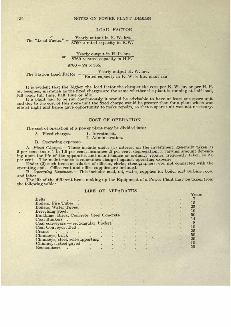
8/20/2019 notes on powerplant.pdf
http://slidepdf.com/reader/full/notes-on-powerplantpdf 138/202
132
NOTES
ON POWER
PLANT
DESIGN
LOAD
FACTOR
Yearly output
in
K.
W.
hrs.
The
Load
Factor
=
^^Ti
.
.
.
^ w
8760
x
rated
capacity
in K.W.
Yearly output
in H. P.
hrs.
8760 X
rated
capacity
in
H.P.
8760
=
24
x
365.
Yearly output
K.
W.
hrs.
The
Station
Load
Factor
=
-p
.
,
rr :
w
, :
Rated
capacity
in K.
W.
x
hrs.
plant
ran
It
is evident
that
the
higher
the
load
factor the
cheaper
the cost
per
K.
W.
hr.
or
per
H.
P.
hr.
becomes,
inasmuch
as
the
fixed
charges
are
the
same
whether
the
plant
is
running
at
half
load,
full
load,
full
time,
half time
or
idle.
If
a
plant
had to
be
run
continuously
it
would
be advisable
to
have at least one
spare
unit
and
due
to
the
cost
of
this
spare
unit the
fixed
charge
would
be
greater
than for
a
plant
which
was
idle
at
night
and
hence
gave
opportunity
to
make
repairs,
so
that
a
spare
unit
was
not
necessary.
COST
OF
OPERATION
The
cost
of
operation
of
a
power plant
may
be
divided
into:
A.
Fixed
charges.
1.
Investment.
2. Administration.
B.
Operating
expenses.
A.
Fixed
Charges.
These
include
under
(1)
interest on
the
investment, generally
taken
as
5
per
cent;
taxes
1
to
1.5
per
cent;
insurance
.5
per
cent; depreciation,
a varying
amount
depend-
ing upon
the
life
of the
apparatus
and
maintenance
or
ordinary
repairs,
frequently
taken
as 2.5
per
cent.
The
maintenance
is
sometimes
charged against
operating
expense.
Under
(2)
such items
as
salaries
of
officers,
clerks,
stenographers,
etc.
not
connected
with
the
operating
end.
Office
rent
and
office
supplies
are included.
B.
Operating
Expenses.
This
includes
coal,
oil,
water,
supplies
for boiler
and turbine
room
and labor.
The life of
the
different items
making
up
the
Equipment
of
a
Power
Plant
may
be
taken
from
the
following
table:
LIFE
OF
APPARATUS
Years
Belts
Boilers,
Fire
Tubes
15
Boilers,
Water Tubes.
Breeching
Steel
........
Buildings; Brick,
Concrete,
Steel Concrete
.....
50
Coal
Bunkers
.
Coal
conveyors
rectangular,
bucket
Coal
Conveyor;
Belt
....
Cranes
. .
Chimneys,
brick ........
Chimneys,
steel, self-supporting
....
Chimneys,
steel
guyed
.
. .
Economizers
......
20
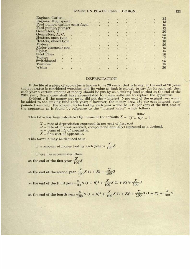
8/20/2019 notes on powerplant.pdf
http://slidepdf.com/reader/full/notes-on-powerplantpdf 139/202
NOTES
ON
POWER
PLANT
DESIGN
133
Engines:
Corliss
.
.
.
.
.
.
.
.
. .25
Engines
:
High speed
.
15
Feed
pumps,
turbine
centrifugal
15
Feed
pumps,
plunger
12
Generators,
D. C.
........
20
Generators,
A.
C.
. .
.
.
.
. .
.
. .
25
Heaters,
open
type
..........
20
Heaters,
closed
type
.........
10
Motors
20
Motor
generator
sets
15
Piping
15
Steel
Flues
.
10
Stokers
............ 7
Switchboard
........... 25
Turbines
15
Wiring
20
DEPRECIATION
If
the
life
of a
piece
of
apparatus
is known
to
be 20
years,
that
is
to
say,
at the
end of
20
years
the
apparatus
is
considered worthless
and
its
value
as
junk
is
enough
to
pay
for
its
removal,
then
each
year
a
certain
amount
of
money
should
be
put
by
as
a
sinking
fund
so
that at
the
end
of the
20th
year,
this
money
shall have
accumulated
to
a
sum
sufficient
to
replace
the
apparatus.
Evidently
if
the
money
put away
did
not
draw
interest,
5
per
cent of the
original
cost
would
be
added
to
the
sinking
fund
each
year;
if
however,
the
money
drew
4^
per
cent
interest,
com-
pounded
annually,
the amount
to
be
laid
by
each
year
would
be 3.19
per
cent of the first
cost of
the
apparatus
as
is
found
by
reference
to
the
interest
table
which
follows:
IQOfl
This
table
has
been
calculated
by
means
of the
formula
X
=
Q
_|_
mn
_
j
X
=
rate
of
depreciation
expressed
in
per
cent
of first
cost.
R
=
rate
of interest
received,
compounded
annually;
expressed
as
a
decimal.
n
=
years
of
life
of
apparatus.
S
=
first cost
of
apparatus.
This
formula
may
be
deduced
thus:
X
The
amount
of
money
laid
by
each
year
is
-JQQ^
There
has
accumulated
then
at
the
end
of the first
year
-j
~
S
X
X
at the
end
of
the
second
year
-TT
(1
+
-^)
+
~
X
X
X
at
the end
of the third
year
~8
(1
+
.R)
2
+
-^-S
(1
+
R)
+
-^8
at
the
end of
the
fourth
year
--S
(1
+
R)
3
+
(1
+
R)
2
+
j^-S
( +)+
-^
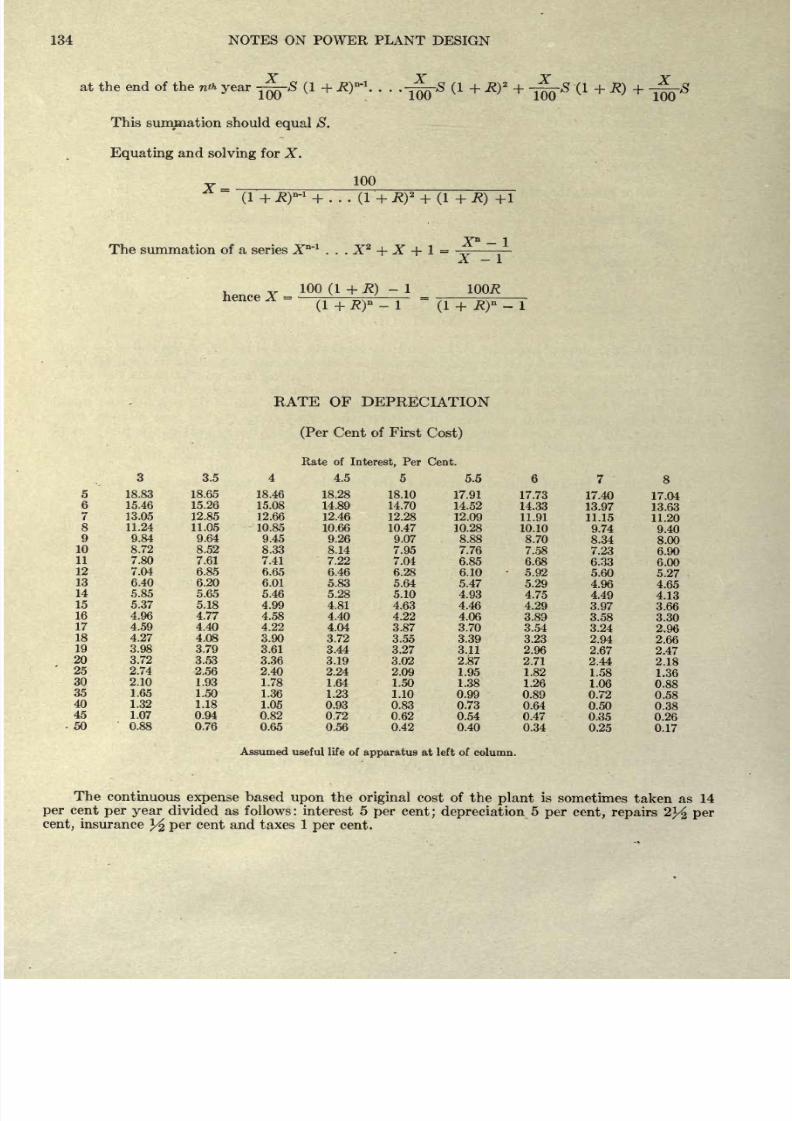
8/20/2019 notes on powerplant.pdf
http://slidepdf.com/reader/full/notes-on-powerplantpdf 140/202
134
NOTES
ON POWER PLANT
DESIGN
at
the
end
of
the n*
year
~r-S
(1
+
R)'
1
-fjLs
(1
+
R)
2
+
-^-S
(1
+
R)
+
1UU
1UU
1UU
This
summation should
equal
S.
Equating
and
solving
for
X.
100
(1
+
R)-
1
+
. .
.
(1
+
R)
2
+
(1
+
R)
+1
X*
-
1
The summation
of a
series X*~
l
. . .
X
2
+
X
+
1
=
X
-
1
,
v
100
(1
+
K)
-
1
IOOR
hence X
=
-
~
=
(1
+
R)
-
1
(1
+
R)
-
1
RATE
OF
DEPRECIATION
(Per
Cent
of
First
Cost)
Rate
of
Interest,
Per
Cent.
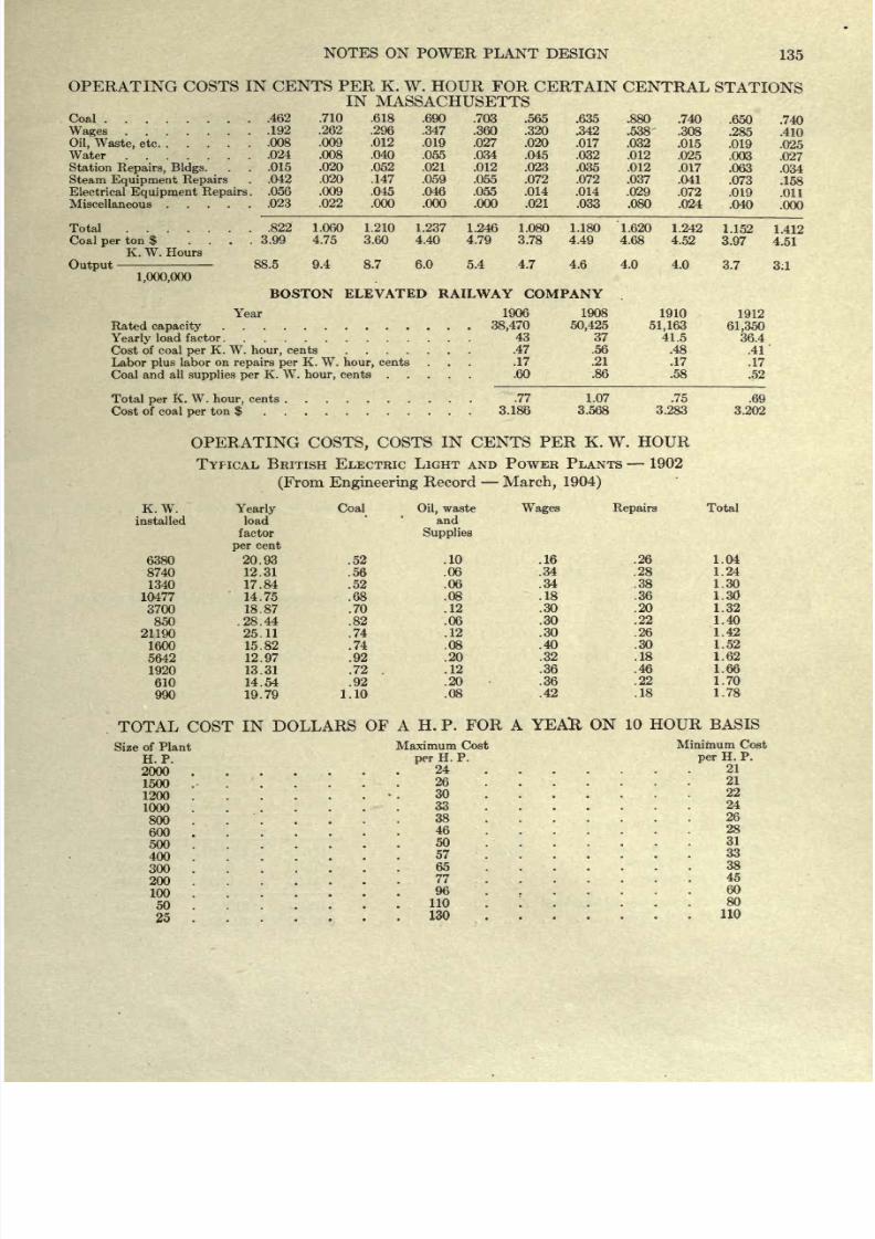
8/20/2019 notes on powerplant.pdf
http://slidepdf.com/reader/full/notes-on-powerplantpdf 141/202
NOTES ON
POWER PLANT
DESIGN
135
OPERATING
COSTS
IN
CENTS
PER
K.
W.
HOUR
FOR CERTAIN
CENTRAL
STATIONS
IN
MASSACHUSETTS
Coal
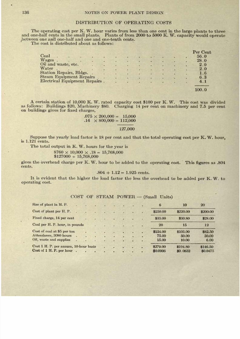
8/20/2019 notes on powerplant.pdf
http://slidepdf.com/reader/full/notes-on-powerplantpdf 142/202
136
NOTES
ON POWER
PLANT
DESIGN
DISTRIBUTION OF
OPERATING
COSTS
The
operating
cost
per
K.
W. hour varies from
less than
one
cent
in the
large
plants
to
three
and
one-half
cents
in
the
small
plants.
Plants
of
from
2000
to
5000
K.
W.
capacity
would
operate
.between
one
and one-half and
one and
one-tenth cents.
The
cost is
distributed
about
as
follows:
Coal .
Wages
....
Oil and
waste,
etc.
Water
....
Station
Repairs,
Bldgs.
.
Steam
Equipment Repairs
Electrical
Equipment Repairs
Per
Cent
56.0
28.0
2.0
2.0
1.6
6.3
4.1
100.0
A
certain station
of
10,000
K.
W.
rated
capacity
cost
$100
per
K.
W.
This
cost
was
divided
as
follows:
Buildings $20,
Machinery
$80.
Charging
14
per
cent
on
machinery
and
7.5
per
cent
on
buildings
gives
for
fixed
charges,
.075
x
200,000
=
15,000
.14
x
800,000= 112,000
127,000
Suppose
the
yearly
load
factor is
18
per
cent and
that
the
total
operating
cost
per
K.
W.
hour,
is
1.121
cents.
The
total
output
in K.
W.
hours
for
the
year
is
8760
x
10,000
x
.18
=
15,768,000
$127000
H-
15,768,000
gives
the
overhead
charge
per
K.
W.
hour to
be
added to
the
operating
cost. This
figures
as
.804
cents.
.804
+
1.12
=
1.925
cents.
It is
evident
that the
higher
the
load
factor
the
less the
overhead
to be
added
per
K.
W.
to
operating
cost.
COST OF
STEAM
POWER
Size of
plant
in H.
P
Cost
of
plant
per
H.
P.
.
.
Fixed
charge,
14
per
cent
......
Coal
per
H.
P.
hour,
in
pounds
Cost
of
coal at
$5
per
ton
.
.
.
.
. .
Attendance,
3080
hours
.......
Oil,
waste
and
supplies
Cost
1
H.
P.
per
annum,
10-hour basis
....
Cost of 1
H. P.
per
hour
(Small
Units)
6
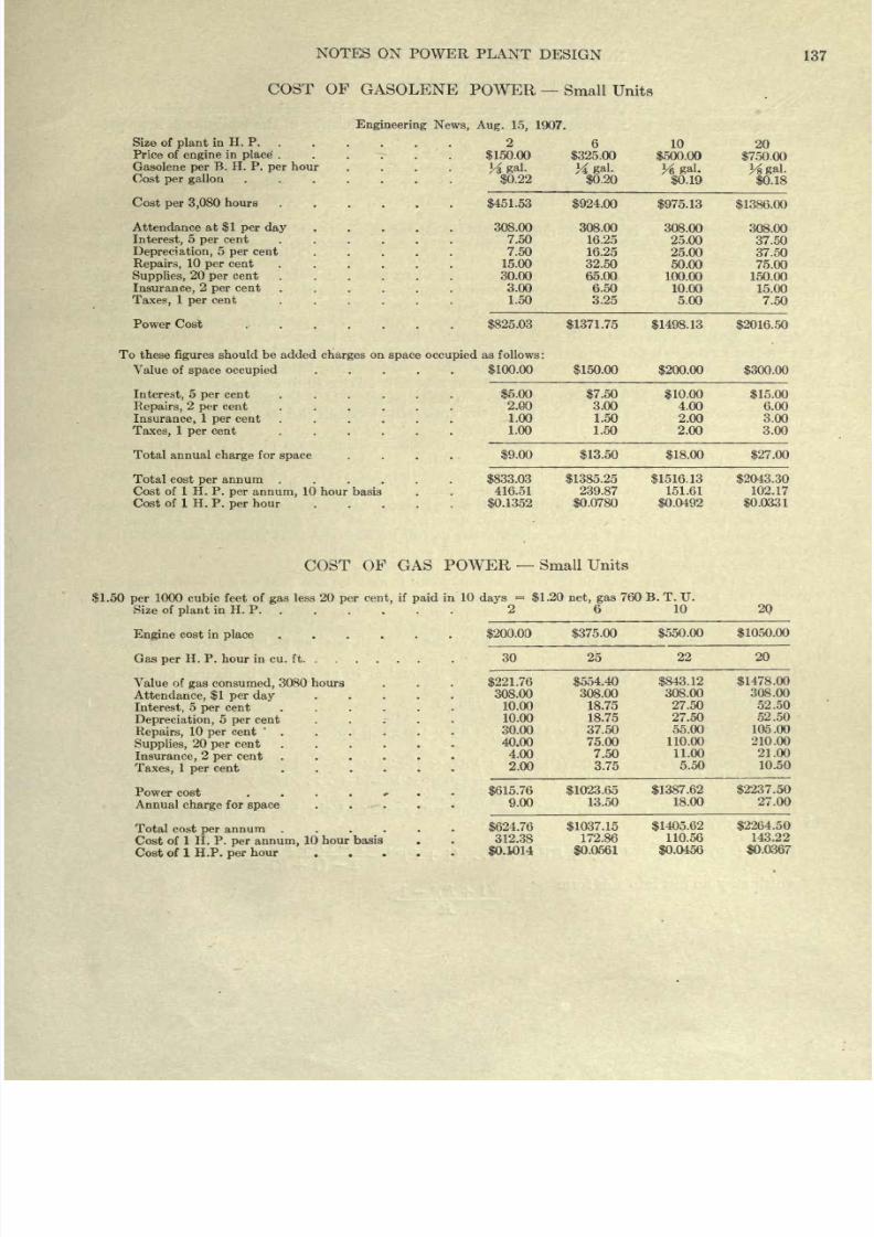
8/20/2019 notes on powerplant.pdf
http://slidepdf.com/reader/full/notes-on-powerplantpdf 143/202
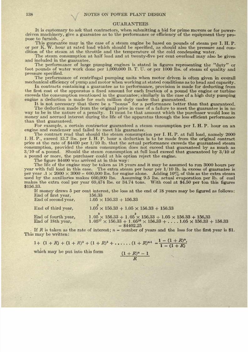
8/20/2019 notes on powerplant.pdf
http://slidepdf.com/reader/full/notes-on-powerplantpdf 144/202
138
K
NOTES
ON POWER
PLANT
DESIGN
GUARANTEES
It is
customary
to
ask
that
contractors,
when
submitting
a bid
for
prime
movers or
for
power-
driven
machinery,
give
a
guarantee
as to
the
performance
or
efficiency
of
the
equipment
they
pro-
pose
to
furnish.
f
-
This
guarantee
may
in
the
case of
a
steam
engine
be
based
on
pounds
of
steam
per
I. H.
P.
or
per
K.
W.
hour
at
rated
load
which should
be
specified,
as
should
also
the
pressure
and
con-
dition
of
the
steam
at
the throttle
and the
temperature
of
the
cold
condensing
water.
The
steam
consumption
at
half
load
and at
twenty-five
per
cent
overload
may
also
be
given
and included
in
the
guarantee.
The
performance
of
large
pumping
engines
is
stated
in
figures
representing
the
duty
or
foot
pounds
of
water
work done
per
1,000,000
B.
T.
U.
or
per
1000
Ibs.
of steam
of
quality
and
pressure
specified.
The
performance
of
centrifugal
pumping
units when motor
driven
is
often
given
in
overall
mechanical
efficiency
of
pump
and motor
when
working
at stated
conditions as
to head
and
capacity.
In
contracts
containing
a
guarantee
as
to
performance,
provision
is
made
for
deducting
from
the
first
cost
of
the
apparatus
a
fixed amount for
each
fraction of
a
pound
the
engine
or
turbine
exceeds
the
consumption
mentioned
in the
guarantee;
similarly
in the
case
of
a
high
duty pumping
engine
a
deduction is
made
for each
million
duty
under
that
guaranteed.
It is
not
necessary
that
there be
a bonus for
a
performance
better
than that
guaranteed.
The
deduction
made
from
the
original price
in
case
of
a
failure
to
meet
the
guarantee
is
in
no
way
to
be
in the
nature
of
a
penalty.
It must
be
that amount which
the
purchaser
would
lose in
money
and
accrued
interest
during
the
life
of
the
apparatus
through
the
less efficient
performance
than that
guaranteed.
For
example,
a certain contractor
guaranteed
a steam
consumption per
I.
H.
P. hour
on
an
engine
and condenser and
failed
to meet
his
guarantee.
The
contract read
that should
the
steam
consumption
per
I.
H.
P.
at
full
load,
namely
2000
I.
H.
P.,
exceed 13.7 Ibs.
per
I. H.
P. hour a
deduction
is to be
made
from
the
original
contract
price
at
the
rate
of
$4400
per
1/10
Ib.
that
the actual
performance
exceeds
the
guaranteed
steam
consumption,
provided
the steam
consumption
does
not
exceed
that
guaranteed
by
as
much
as
3/10
of
a
pound.
Should
the
steam
consumption
at full
load
exceed
that
guaranteed
by
3/10
of
a
pound
or
more,
the
purchaser
could at
his
option
reject
the
engine.
The
figure
$4400
was arrived
at
in
this
way
:
The
life
of
the
engine
may
be
taken
as 18
years
and
it
may
be
assumed
to
run
3000
hours
per
year
with full
load
in
this
case. The
extra steam
per
hour
per 1/10
Ib.
in
excess
of
guarantee
is
per
year
.1
x
2000
x
3000
=
600,000
Ibs.
for
engine
alone.
Adding
10%
of
this as
the
extra
steam
used
by
the auxiliaries
makes
660,000
Ibs.
Assuming
9.5 Ibs.
actual
evaporation
per
Ib.
of
coal
makes
the extra
coal
per
year
69,474
Ibs. or 34.74
tons.
With
coal at
$4.50
per
ton
this
figures
$156.33.
If
money
draws
5
per
cent
interest,
the
loss
at
the
end
of
18
years
may
be
figured
as
follows :
End
of
first
year,
156.33
End
of
second
year,
1.05
x
156.33
+
156.33
End of third
year,
1.05
x
156.33
+
1.05
x
156.33
+
156.33
End
of
fourth
year,
1,06*X
156.33
+
1.05*X
156.33
+
1.05
x
156.33
+
156.33
End
of
18th
year,
1.05
17
X
156.33
+
1.05
16
x
156.33
+
____
1.05
x
156.33
+
156.33
=
$4402.25
.
If
R
is
taken as
the rate
of
interest;
n
=
number
of
years
and
the
loss
for
the
first
year
is
$1.
This
may
be written:
which
may
be
put
into
this
form
Q
,
n
_
R
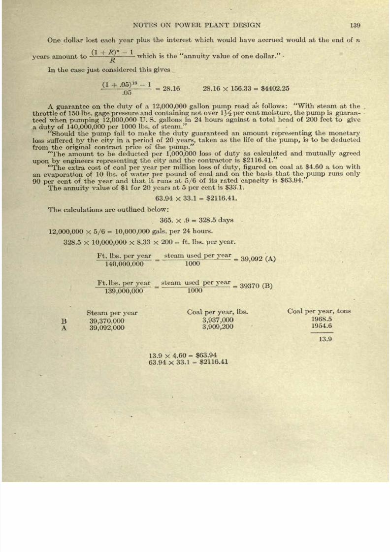
8/20/2019 notes on powerplant.pdf
http://slidepdf.com/reader/full/notes-on-powerplantpdf 145/202
NOTES
ON
POWER
PLANT
DESIGN
139
One dollar
lost each
year
plus
the
interest
which would have accrued
would
at
the
end
of n
(1
+ R}
n
1
years
amount
to
~
which is
the
annuity
value of one dollar.
In
the
case
just
considered
this
gives
(1
+
.05)
18
-
1
.05
=
28.16
28.16
x
156.33
=
$4402.25
A
guarantee
on
the
duty
of
a
12,000,000
gallon pump
read as
follows:
With
steam at
the
throttle
of
150
Ibs.
gage
pressure
and
containing
not
over
1^
per
cent
moisture,
the
pump
is
guaran-
teed
when
pumping
12,000,000
U.
S.
gallons
in 24 hours
against
a total
head of 200
feet
to
give
a
duty
of
140,000,000 per
1000
Ibs.
of
steam.
Should
the
pump
fail
to
make
the
duty guaranteed
an amount
representing
the
monetary
loss
suffered
by
the
city
in a
period
of
20
years,
taken
as the
life of the
pump,
is
to
be
deducted
from
the
original
contract
price
of the
pump.
The
amount
to
be
deducted
per
1,000,000
loss
of
duty
as
calculated
and
mutually agreed
upon
by
engineers
representing
the
city
and
the
contractor
is
$2116.41.
The extra
cost
of
coal
per
year
per
million
loss
of
duty,
figured
on coal
at
$4.60
a
ton with
an
evaporation
of
10
Ibs.
of water
per
pound
of coal
and
on
the
basis
that
the^ump
runs
only
90
per
cent
of
the
year
and
that
it runs
at
5/6
of its
rated
capacity
is
$63.94.'
The
annuity
value
of
$1
for
20
years
at
5
per
cent
is
$33'.
1.
63.94
x
33.1
=
$2116.41.
The
calculations
are outlined
below:
365.
x
.9
=
328.5
days
12,000,000
x
5/6
=
10,000,000
gals,
per
24
hours.
328.5
x
10,000,000
x
8.33
x
200
=
ft.
Ibs.
per
year.
Ft.
Ibs.
per
year
_
steam
used
per
year
_
\
140,000,000
1000
Ft.
Ibs.
per year
_
steam
used
per
year
139,000,000
~
1000
Steam
per
year
Coal
per
year,
Ibs.
Coal
per
year,
tons
B
39,370,000
3,937,000
1968.5
A
39,092,000
3,909,200
1954.6
13.9
13.9
x
4.60
=
$63.94
63.94
x
33.1
=
$2116.41
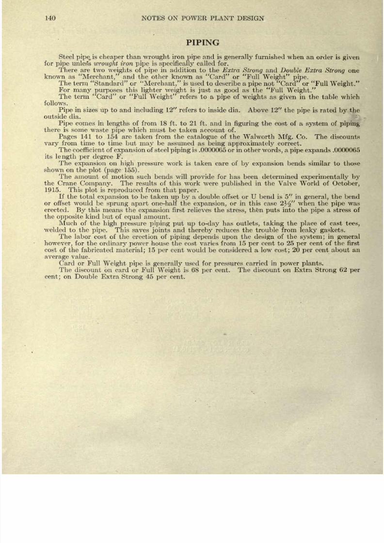
8/20/2019 notes on powerplant.pdf
http://slidepdf.com/reader/full/notes-on-powerplantpdf 146/202
140
NOTES
ON
POWER PLANT
DESIGN
PIPING
Steel
pipe,
is
cheaper
than
wrought
iron
pipe
and is
generally
furnished
when
an order
is
given
for
pipe
unless
wrought
iron
pipe
is
specifically
called
for.
There are two
weights
of
pipe
in
addition to the
Extra
Strong
and Double
Extra
Strong
one
known as
Merchant,
and the other known as
Card or Full
Weight pipe.
The
term Standard
or
Merchant,
is
used
to
describe
a pipe
not
Card
or
Full
Weight.
For
many
purposes
this
lighter
weight
is
just
as
good
as
the
Full
Weight.
The
term
Card or Full
Weight
refers
to
a
pipe
of
weights
as
given
in
the table which
follows.
Pipe
in
sizes
up
to and
including
12
refers to
inside
dia.
Above
12
the
pipe
is rated
by
the
outside
dia.
Pipe
comes in
lengths
of
from
18
ft.
to
21
ft. and
in
figuring
the
cost
of a
system
of
piping
there is
some
waste
pipe
which
must
be
taken
account of.
Pages
141
to
154
are
taken
from
the
catalogue
of
the Walworth
Mfg.
Co.
The
discounts
vary
from time
to
time but
may
be
assumed
as
being
approximately
correct.
The
coefficient
of
expansion
of steel
piping
is
.0000065 or
in
other
words,
a
pipe
expands
.0000065
its
length
per
degree
F.
The
expansion
on
high
pressure
work
is taken
care
of
by
expansion
bends similar to those
shown
on
the
plot
(page
155).
The
amount
of
motion such
bends
will
provide
for has
been
determined
experimentally
by
the Crane
Company.
The
results
of
this work were
published
in
the
Valve
World
of
October,
1915.
This
plot
is
reproduced
from
that
paper.
If
the
total
expansion
to be taken
up by
a double
offset or U
bend is 5
in
general,
the
bend
or
offset would
be
sprung
apart
one-half the
expansion,
or
in
this case
2j/
when
the
pipe
was
erected.
By
this
means
the
expansion
first relieves the
stress,
then
puts
into
the
pipe
a
stress
of
the
opposite
kind
but of
equal
amount.
Much of
the
high
pressure
piping put up
to-day
has
outlets, taking
the
place
of
cast
tees,
welded
to the
pipe.
This
saves
joints
and
thereby
reduces
the trouble
from
leaky gaskets.
The
labor
cost
of
the erection
of
piping
depends
upon
the
design
of the
system;
in
general
however,
for the
ordinary
power
house
the
cost
varies from 15
per
cent
to 25
per
cent of
the
first
cost
of
the
fabricated
material;
15
per
cent
would
be
considered
a
low
cost;
20
per
cent
about
an
average
value.
Card
or Full
Weight
pipe
is
generally
used
for
pressures
carried in
power plants.
The
discount on
card
or
Full
Weight
is 68
per
cent. The discount
on
Extra
Strong
62
per
cent;
on Double
Extra
Strong
45
per
cent.
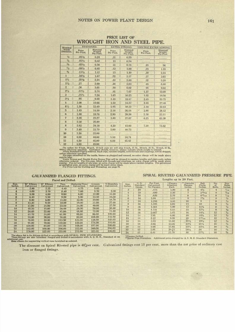
8/20/2019 notes on powerplant.pdf
http://slidepdf.com/reader/full/notes-on-powerplantpdf 147/202
NOTES
ON
POWER
PLANT
DESIGN
141
PRICE
LIST
OF
WROUGHT
IRON AND
STEEL
PIPE.
Nominal
Inside
Diameter.
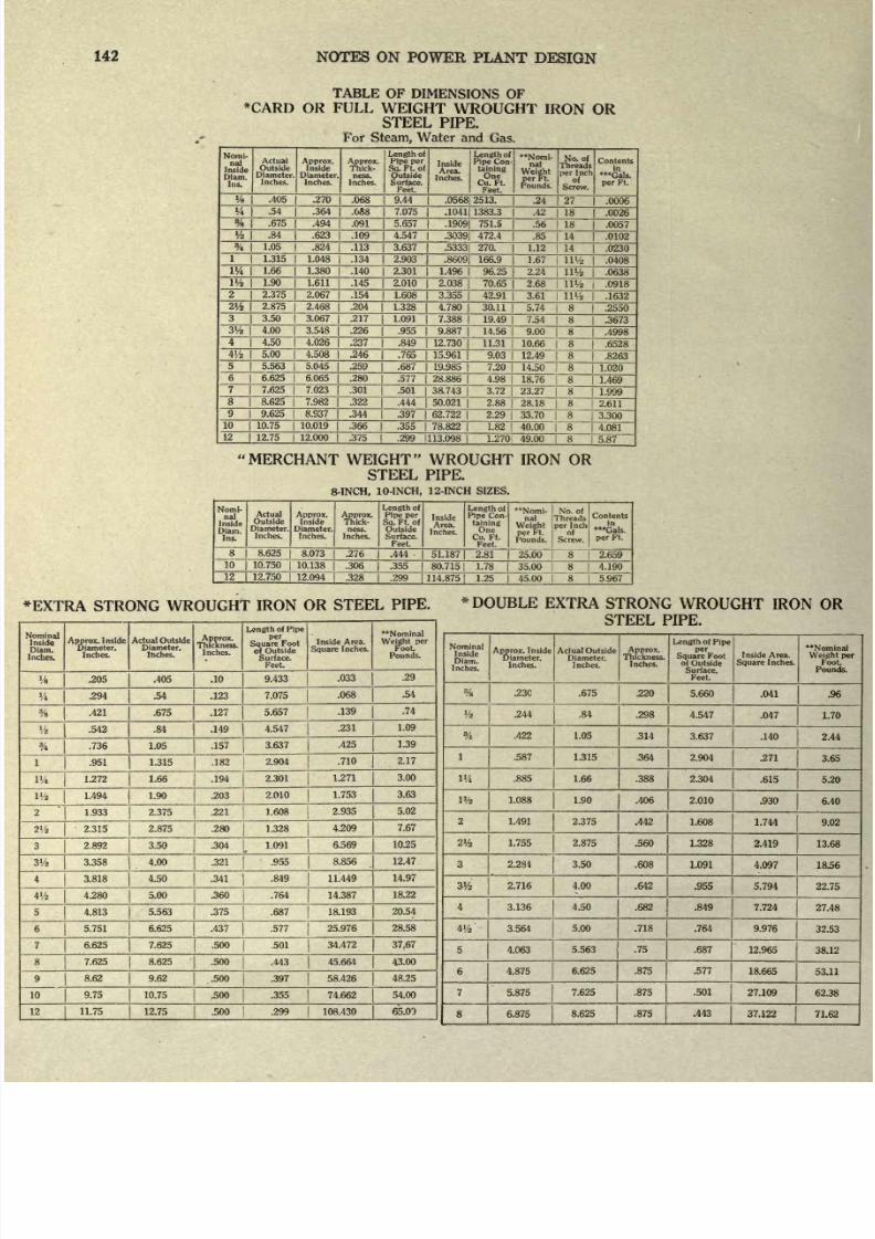
8/20/2019 notes on powerplant.pdf
http://slidepdf.com/reader/full/notes-on-powerplantpdf 148/202
142
NOTES ON
POWER
PLANT
DESIGN
TABLE
OF
DIMENSIONS
OF
*CARD
OR
FULL
WEIGHT
WROUGHT
IRON
OR
STEEL
PIPE.
For
1
Steam,
Water
and
Gas.
Nomi-
nal
Inside
Diam.
Ins.
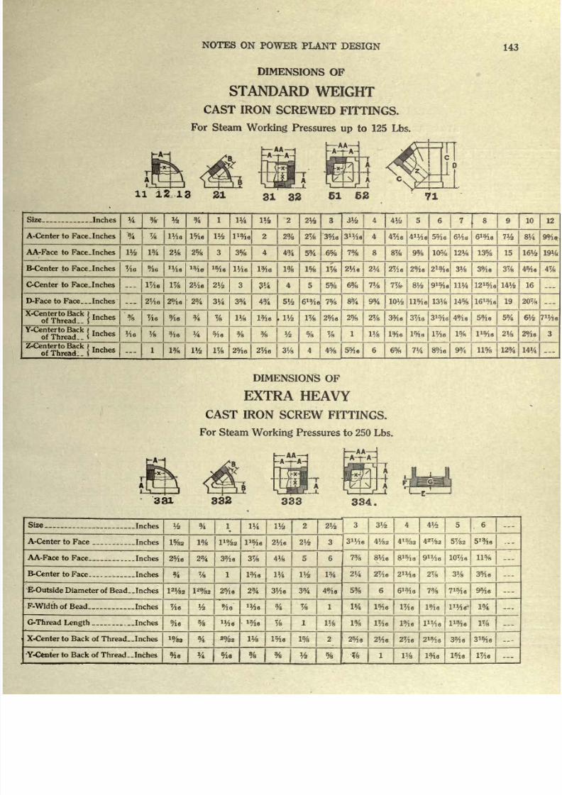
8/20/2019 notes on powerplant.pdf
http://slidepdf.com/reader/full/notes-on-powerplantpdf 149/202
NOTES
ON
POWER
PLANT
DESIGN
143
DIMENSIONS
OF
STANDARD
WEIGHT
CAST
IRON
SCREWED
FITTINGS.
For
Steam
Working
Pressures
up
to
125
Lbs.
Size
Inches
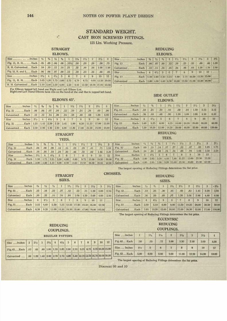
8/20/2019 notes on powerplant.pdf
http://slidepdf.com/reader/full/notes-on-powerplantpdf 150/202
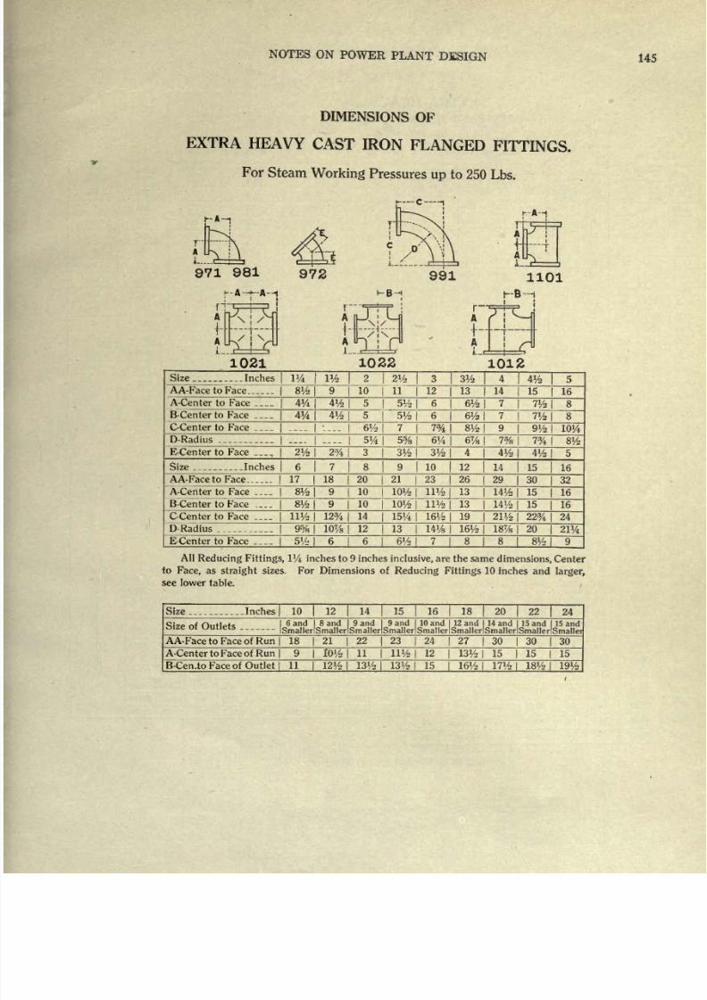
8/20/2019 notes on powerplant.pdf
http://slidepdf.com/reader/full/notes-on-powerplantpdf 151/202
NOTES
ON
POWER
PLANT
DESIGN
145
DIMENSIONS
OF
EXTRA
HEAVY
CAST
IRON
FLANGED
FITTINGS.
For
Steam
Working
Pressures
up
to
250
Lbs.
1021
1022
1012
Size
..Inches
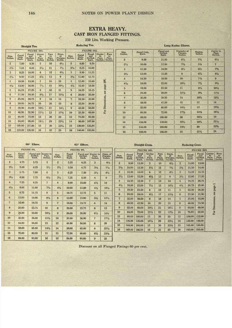
8/20/2019 notes on powerplant.pdf
http://slidepdf.com/reader/full/notes-on-powerplantpdf 152/202
146
NOTES
ON
POWER PLANT DESIGN
Straight
Tee.
EXTRA
HEAVY.
CAST
IRON
FLANGED
FITTINGS.
250 Lbs.
Working
Pressure.
Reducing
Tee.
Long
Radius
Elbows.
FIGURE
1011.
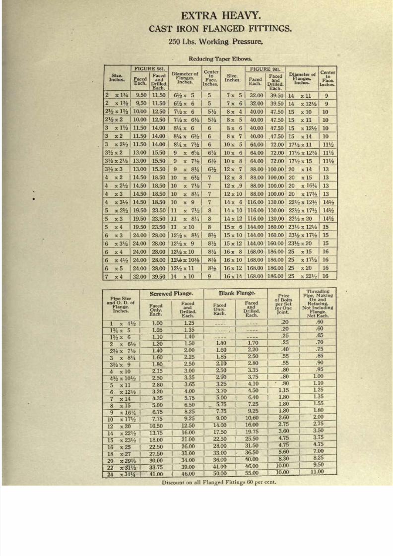
8/20/2019 notes on powerplant.pdf
http://slidepdf.com/reader/full/notes-on-powerplantpdf 153/202
EXTRA
HEAVY.
CAST
IRON
FLANGED
FITTINGS.
250
Lbs.
Working
Pressure.
Reducing
Taper
Elbows.
Size.
Inches.
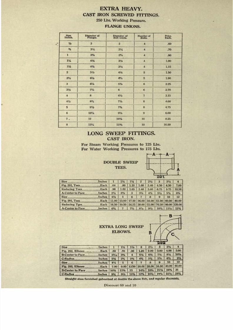
8/20/2019 notes on powerplant.pdf
http://slidepdf.com/reader/full/notes-on-powerplantpdf 154/202
EXTRA
HEAVY.
CAST
IRON
SCREWED
FITTINGS.
250 Lbs.
Working
Pressure.
FLANGE
UNIONS.
Size.
Inches.
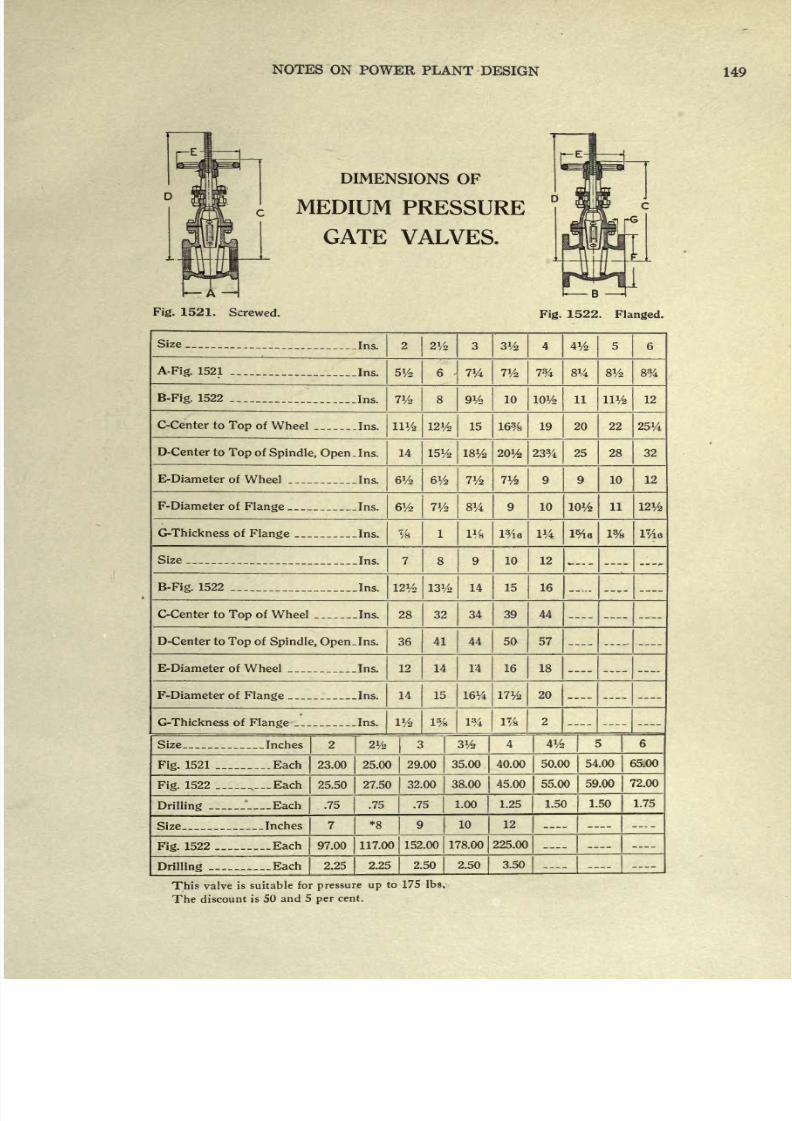
8/20/2019 notes on powerplant.pdf
http://slidepdf.com/reader/full/notes-on-powerplantpdf 155/202
NOTES
ON
POWER
PLANT
DESIGN
149
DIMENSIONS
OF
MEDIUM
PRESSURE
GATE
VALVES.
Fig.
1521.
Screwed.
B
4
Fig.
1522.
Flanged.
Size
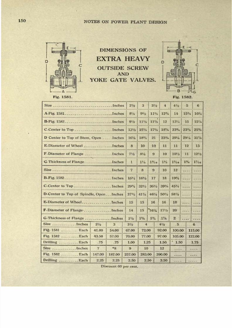
8/20/2019 notes on powerplant.pdf
http://slidepdf.com/reader/full/notes-on-powerplantpdf 156/202
150
NOTES
ON
POWER
PLANT
DESIGN
OUTSIDE
SCREW
AND
YOKE
GATE VALVES.
Fig.
1581.
Size
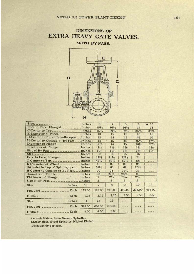
8/20/2019 notes on powerplant.pdf
http://slidepdf.com/reader/full/notes-on-powerplantpdf 157/202
NOTES
ON
POWER
PLANT
DESIGN
151
DIMENSIONS
OF
EXTRA HEAVY
GATE
VALVES.
WITH
BY-PASS.
Size
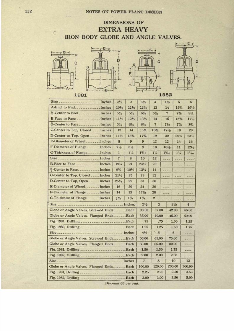
8/20/2019 notes on powerplant.pdf
http://slidepdf.com/reader/full/notes-on-powerplantpdf 158/202
152
NOTES ON
POWER
PLANT
DESIGN
DIMENSIONS
OF
EXTRA
HEAVY
IRON
BODY
GLOBE AND
ANGLE
VALVES.
k...
..-->
L-
1
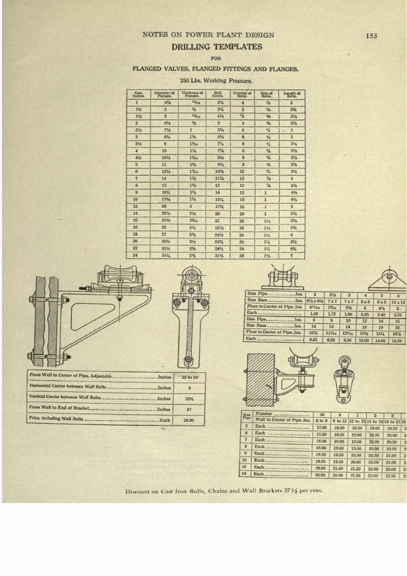
8/20/2019 notes on powerplant.pdf
http://slidepdf.com/reader/full/notes-on-powerplantpdf 159/202
NOTES
ON
POWER
PLANT
DESIGN
DRILLING
TEMPLATES
FOR
FLANGED
VALVES,
FLANGED
FITTINGS AND
FLANGES.
250 Lbs.
Working
Pressure.
153
Size.
Inches.
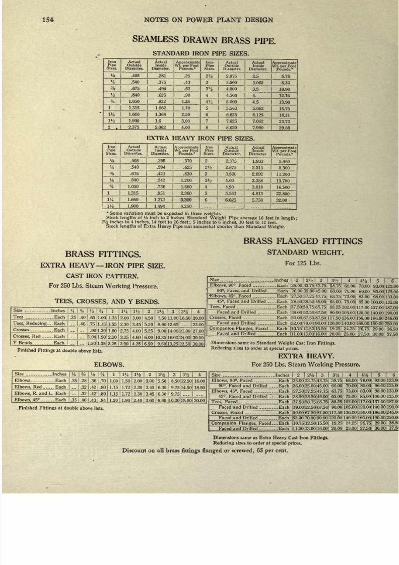
8/20/2019 notes on powerplant.pdf
http://slidepdf.com/reader/full/notes-on-powerplantpdf 160/202
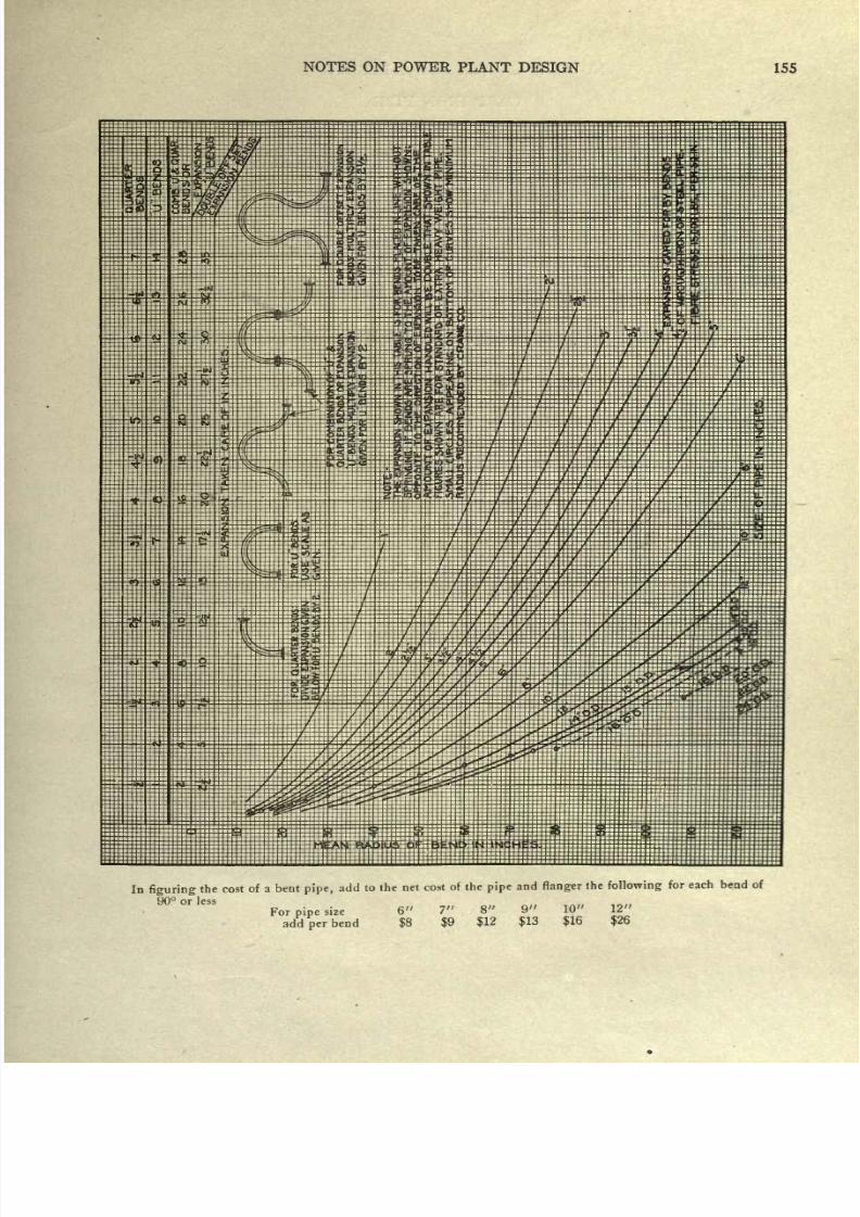
8/20/2019 notes on powerplant.pdf
http://slidepdf.com/reader/full/notes-on-powerplantpdf 161/202
NOTES
ON
POWER
PLANT
DESIGN
155
In
figuring
the
90
or less
cost
of
a
bent
pipe,
add
to
the
net cost
of
the
pipe
and
flanger
the
following
for each
bend of
For
pipe
size
6
7
8
9
10
12
add
per
bend
$8
$9
$12
$13
$16
$26
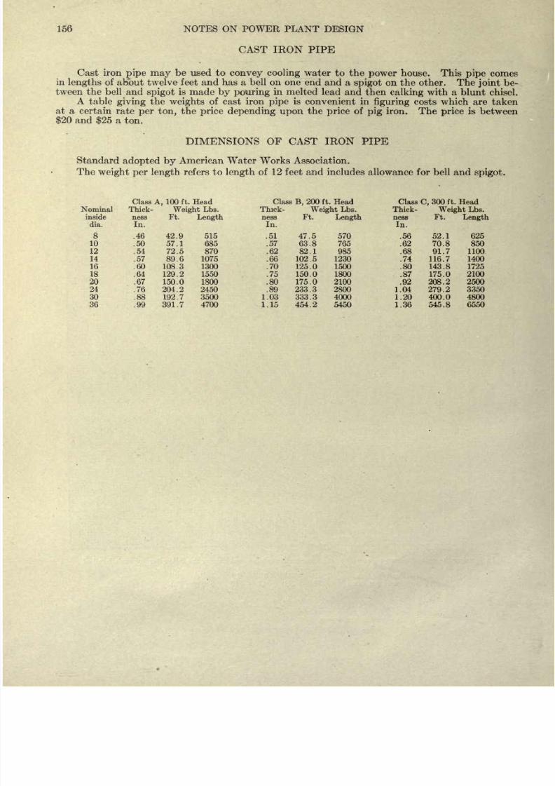
8/20/2019 notes on powerplant.pdf
http://slidepdf.com/reader/full/notes-on-powerplantpdf 162/202
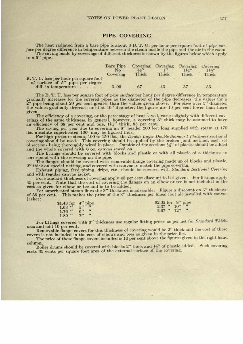
8/20/2019 notes on powerplant.pdf
http://slidepdf.com/reader/full/notes-on-powerplantpdf 163/202
NOTES
ON
POWER PLANT
DESIGN
157
PIPE
COVERING
The
heat radiated from a bare
pipe
is about
3
B. T.
U.
per
hour
per
square
foot of
pipe
sur-
face
per degree
difference
in
temperature
between the
steam inside the
pipe
and
the air in
the
room.
The
saving
made
by
coverings
of
different
thickness
is
shown by
the
figures
below
which
apply
to
a 5
pipe:
B.
T.
U.
loss
per
hour
per square
foot
of surface
of
5
pipe per
degree
diff.
in
temperature
....
Bare
Pipe
No
Covering
3.00
Covering
Covering
Covering Covering
Thick Thick
Thick
Thick
.67 .43 .37 .33
The
B.
T.
U.
loss
per square
foot of
pipe
surface
per
hour
per
degree
difference in
temperature
gradually
increases for
the covered
pipes
as
the diameter
of the
pipe
decreases,
the values
for
a
2
pipe
being
about
20
per
cent
greater
than the
values
given
above.
For
sizes
over
5
diameter
the values
gradually
decrease
until at
10
diameter,
the
figures
are
10
per
cent
lower
than
those
given.
The
efficiency
of a
covering,
or the
percentage
of
heat
saved,
varies
slightly
with
different cov-
erings
of the
same
thickness,
in
general,
however,
a
covering
3
thick
may
be assumed to
have
an
efficiency
of 88
per
cent
and
one,
1J4
thick,
85
per
cent.
The
saving per
year
due to
covering
an 8
header
200
feet
long
supplied
with
steam
at
170
Ibs.
absolute
superheated
100
may
be
figured
thus.
For
high
pressure
steam,
100 to
150
Ibs.,
the
Double
Layer
Double
Standard
Thickness
sectional
covering
should be used.
This
covering
should
be
applied
by
the
broken
joint
method,
each
set
of
sections
being
thoroughly
wired
in
place.
Outside
of the sections
%
of
plastic
should
be added
and
the
whole
covered
with 8 oz.
canvas
sewed
on.
The
fittings
should
be
covered
with
blocks
and
plastic
or
with
all
plastic
of
a thickness
to
correspond
with the
covering
on
the
pipe.
The
flanges
should
be
covered
with
removable
flange covering
made
up
of
blocks
and
plastic,
1
thick on
special
netting,
and covered
with
canvas to
match
the
pipe
covering.
Exhaust
piping,
feed
piping,
drips,
etc.,
should
be covered
with
Standard
Sectional
Covering
and with
regular
canvas
jacket.
For standard thickness
of
covering apply
45
per
cent
discount
to list
given.
For
fittings
apply
45
per
cent.
Note that
the cost
of
covering,
the
flanges
on
an
elbow
or
tee
is
not
included
in
the
cost
as
given
for
elbow
or
tee
and
is to
be
added.
For
superheated
steam
lines
the
3
thickness
is advisable.
Figure
a
discount
on
3
thickness
of 35
per
cent. This
makes
the
price
of
the
3 thickness
per
lineal
foot
all
installed
with
canvas
jacket:
4
nine
$2.05
for
8
pipe
5
2.37
10
6
2.67
12
7.
For
fittings
covered
with
3
thickness
use
regular
fitting
prices
as
per
list
for
Standard
Thick-
ness and add 10
per
cent.
Removable
flange
covers
for
this
thickness
of
covering
would
be
2'
thick
and
the
cost
of
thes
covers
is not included
in
the cost
of
elbows
and tees
as
given
in the
price
list.
The
price
of these
flange
covers
installed
is
10
per
cent
above
the
figures
given
in
the
right
1
Boiler
drums
should
be covered
with
blocks
2 thick
and
K
of
plastic
added.
Such
covering
costs
35 cents
per
square
foot
area
of
the
external
surface
of
the
covering.
&1.43
for
1.63
1.76
1.89
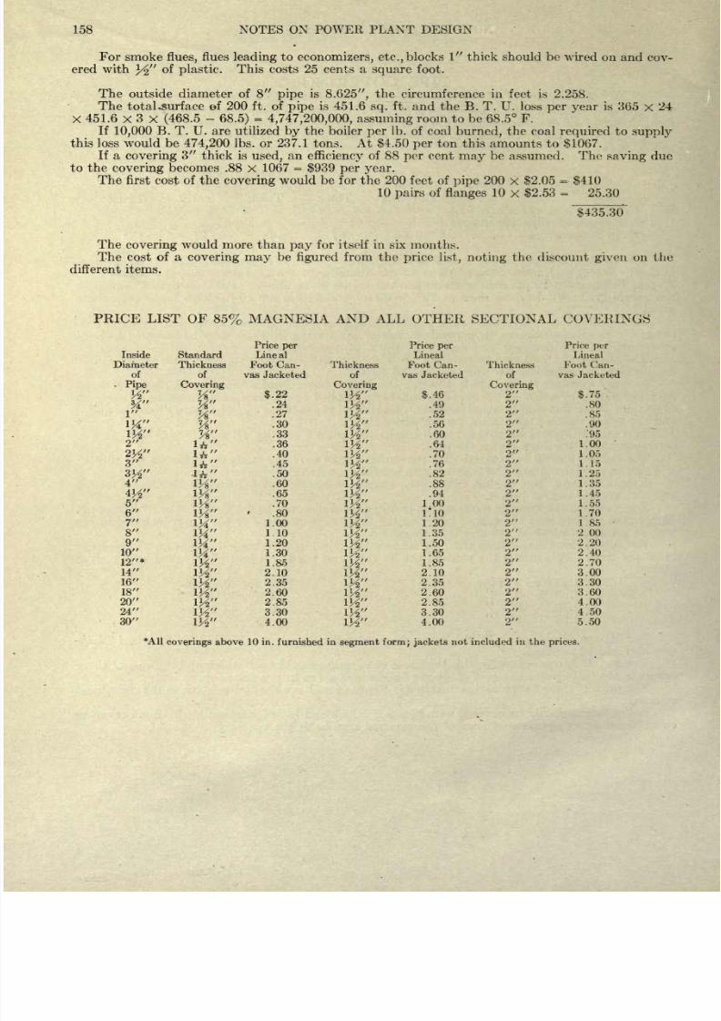
8/20/2019 notes on powerplant.pdf
http://slidepdf.com/reader/full/notes-on-powerplantpdf 164/202
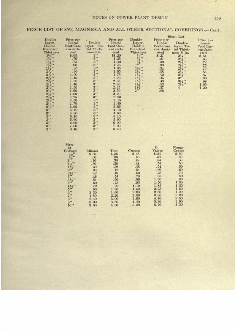
8/20/2019 notes on powerplant.pdf
http://slidepdf.com/reader/full/notes-on-powerplantpdf 165/202
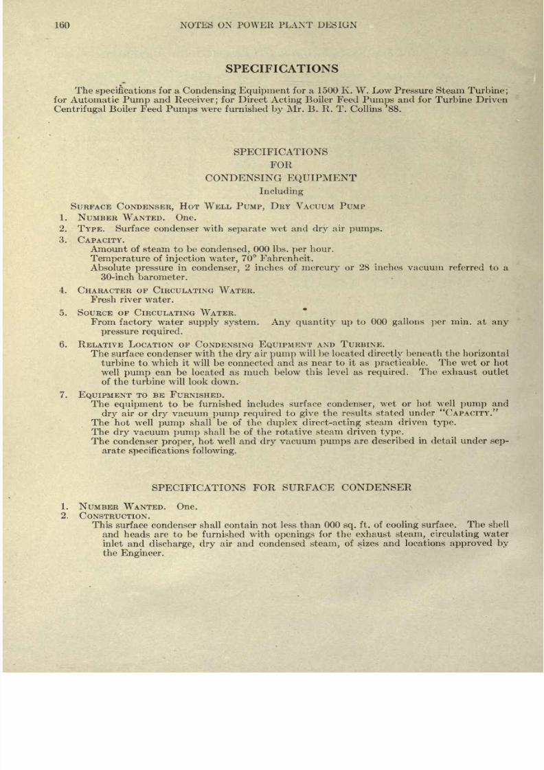
8/20/2019 notes on powerplant.pdf
http://slidepdf.com/reader/full/notes-on-powerplantpdf 166/202
160
NOTES ON
POWER
PLANT
DESIGN
SPECIFICATIONS
The
specifications
for
a
Condensing
Equipment
for a 1500 K.
W.
Low Pressure Steam
Turbine;
for
Automatic
Pump
and
Receiver;
for Direct
Acting
Boiler Feed
Pumps
and
for
Turbine Driven
Centrifugal
Boiler
Feed
Pumps
were
furnished
by
Mr.
B. R. T.
Collins '88.
SPECIFICATIONS
FOR
CONDENSING
EQUIPMENT
Including
SURFACE
CONDENSER,
HOT
WELL
PUMP,
DRY VACUUM PUMP
1. NUMBER
WANTED.
One.
2.
TYPE. Surface
condenser
with
separate
wet
and
dry
air
pumps.
3.
CAPACITY.
Amount
of
steam
to
be
condensed,
000
Ibs.
per
hour.
Temperature
of
injection
water,
70
Fahrenheit.
Absolute
pressure
in
condenser,
2 inches of
mercury
or
28
inches
vacuum
referred
to
a
30-inch barometer.
4.
CHARACTER
OF
CIRCULATING WATER.
Fresh
river water.
5.
SOURCE
OF CIRCULATING
WATER.
From
factory
water
supply
system. Any quantity
up
to
000
gallons per
min. at
any
pressure
required.
6. RELATIVE
LOCATION
OF CONDENSING
EQUIPMENT
AND
TURBINE.
The
surface
condenser with
the
dry
air
pump
will be
located
directly
beneath the horizontal
turbine to
which
it
will be connected
and
as
near
to
it
as
practicable.
The
wet
or
hot
well
pump
can be located
as
much
below
this
level
as
required.
The
exhaust outlet
of
the
turbine
will
look
down.
7.
EQUIPMENT
TO
BE FURNISHED.
The
equipment
to
be
furnished
includes surface
condenser,
wet or
hot
well
pump
and
dry
air or
dry
vacuum
pump
required
to
give
the results
stated
under CAPACITY.
The
hot
well
pump
shall
be
of
the
duplex
direct-acting
steam
driven
type.
The
dry
vacuum
pump
shall
be of the
rotative
steam
driven
type.
The
condenser
proper,
hot
well and
dry
vacuum
pumps
are
described
in
detail under
sep-
arate
specifications following.
SPECIFICATIONS
FOR SURFACE
CONDENSER
1.
NUMBER
WANTED.
One.
2.
CONSTRUCTION.
This
surface condenser shall contain
not
less
than 000
sq.
ft.
of
cooling
surface.
The shell
and
heads
are
to
be
furnished with
openings
for the
exhaust
steam, circulating
water
inlet
and
discharge,
dry
air and condensed
steam,
of sizes
and
locations
approved
by
the
Engineer.
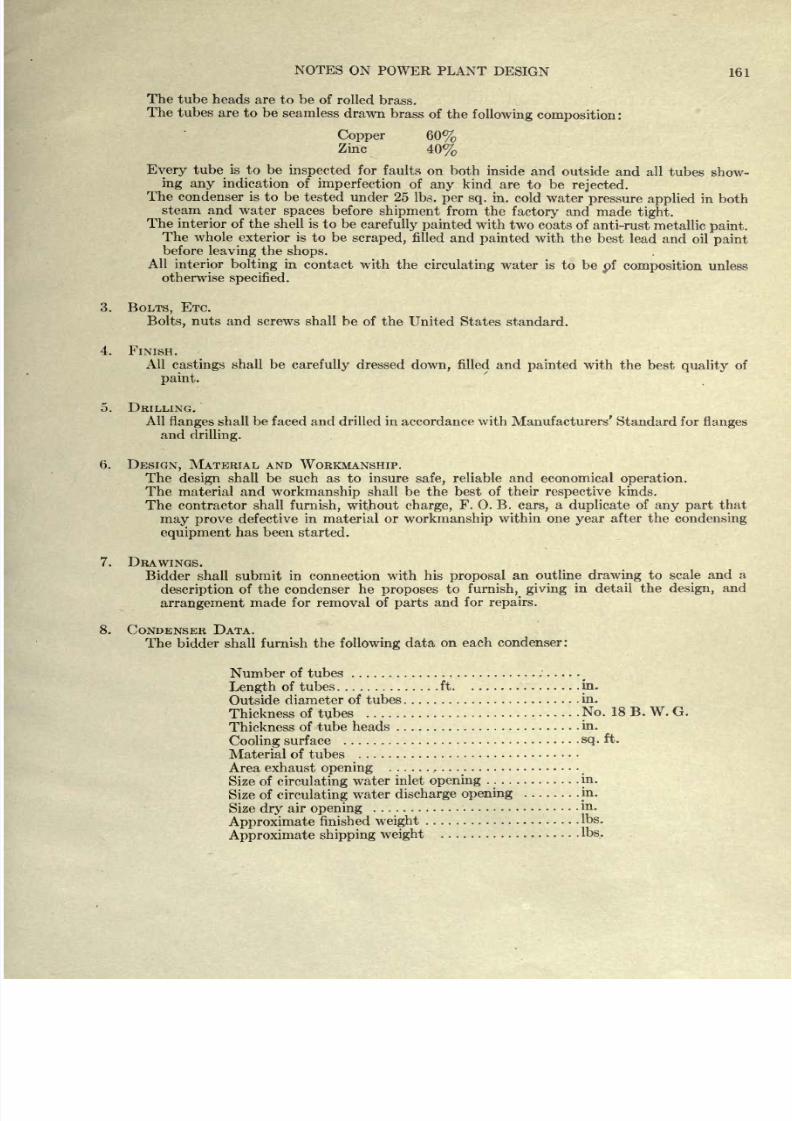
8/20/2019 notes on powerplant.pdf
http://slidepdf.com/reader/full/notes-on-powerplantpdf 167/202
NOTES
ON POWER PLANT
DESIGN
161
The
tube
heads
are
to
be
of
rolled
brass.
The
tubes are
to
be
seamless
drawn
brass
of the
following
composition:
Copper
60%
Zinc
40%
Every
tube
is
to
be
inspected
for faults
on
both
inside
and
outside
and
all
tubes
show-
ing
any
indication
of
imperfection
of
any
kind are
to
be
rejected.
The
condenser
is
to
be
tested under
25 Ibs.
per
sq.
in. cold water
pressure
applied
in
both
steam and
water
spaces
before
shipment
from
the
factory
and
made
tight.
The
interior
of
the
shell is
to
be
carefully painted
with two
coats of
anti-rust
metallic
paint.
The
whole
exterior
is
to
be
scraped,
filled and
painted
with the
best
lead and
oil
paint
before
leaving
the
shops.
All
interior
bolting
in
contact with
the
circulating
water is
to
be
pf
composition
unless
otherwise
specified.
3.
BOLTS,
ETC.
Bolts,
nuts and
screws shall
be
of
the
United
States
standard.
4.
FINISH.
All
castings
shall
be
carefully
dressed
down,
filled and
painted
with
the
best
quality
of
paint.
5.
DRILLING.
All
flanges
shall
be
faced and
drilled
in
accordance with
Manufacturers' Standard for
flanges
and
drilling.
6.
DESIGN,
MATERIAL
AND
WORKMANSHIP.
The
design
shall be such
as
to
insure
safe,
reliable
and
economical
operation.
The
material
and
workmanship
shall be
the
best
of
their
respective
kinds.
The
contractor shall
furnish,
without
charge,
F.
O.
B.
cars,
a
duplicate
of
any
part
that
may
prove
defective
in
material
or
workmanship
within
one
year
after
the
condensing
equipment
has been
started.
7.
DRAWINGS.
Bidder
shall
submit
in connection
with
his
proposal
an
outline
drawing
to
scale
and a
description
of the
condenser
he
proposes
to
furnish,
giving
in detail the
design,
and
arrangement
made
for
removal
of
parts
and
for
repairs.
8.
CONDENSER
DATA.
The
bidder shall
furnish
the
following
data
on
each condenser:
Number
of
tubes
m
Length
of tubes
ft
in.
Outside
diameter
of
tubes
in.
Thickness
of
tubes
No.
18
B.
W.
G.
Thickness
of tube
heads
in.
Cooling
surface
sq.
ft.
Material
of
tubes
Area
exhaust
opening
Size of
circulating
water
inlet
opening
. .
in.
Size
of
circulating
water
discharge
opening
in.
Size
dry
air
opening
in.
Approximate
finished
weight
Ibs.
Approximate
shipping
weight
Ibs.
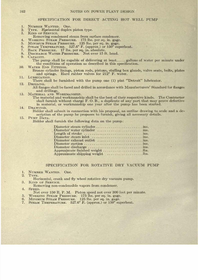
8/20/2019 notes on powerplant.pdf
http://slidepdf.com/reader/full/notes-on-powerplantpdf 168/202
162
NOTES
ON
POWER PLANT
DESIGN
SPECIFICATION
FOR
DIRECT
ACTING
HOT
WELL PUMP
1.
NUMBER
WANTED.
One.
2. TYPE.
Hprizontal
duplex
piston type.
3.
KIND
OF
SERVICE.
Removing
condensed
steam
from
surface
condenser.
4.
WORKING
STEAM
PRESSURE.
175
Ibs.
per
sq.
in.
gage.
5.
MINIMUM
STEAM
PRESSURE.
125
Ibs.
per
sq.
in.
gage.
6.
STEAM
TEMPERATURE. 527.6
F.
(approx.)
or
150
superheat.
7. BACK PRESSURE.
17
Ibs.
per sq.
in. absolute.
8.
DISCHARGE WATER
PRESSURE.
Not
over
15 ft.
head.
9. CAPACITY.
The
pump
shall
be
capable
of
delivering
at
least
gallons
of
water
per
minute
under
the
conditions
of
operation
as
described in
this
specification.
10.
WATER
END
FITTINGS.
Bronze
cylinder
linings,
piston rods,
pistons,
stuffing
box
glands,
valve
seats,
bolts, plates
and
springs.
Hard rubber valves for
212
F. water.
11. LUBRICATION.
There shall be furnished with
the
pump
one
(1)
pint
Detroit
lubricator.
12.
DRILLING.
All
flanges
shall
be
faced
and
drilled
in
accordance with Manufacturers'
Standard
for
flanges
and
drillings.
13.
MATERIAL
AND
WORKMANSHIP.
The
material
and
workmanship
shall be the best of
their
respective
kinds.
The
Contractor
shall
furnish without
charge
F.
O.
B.,
a
duplicate
of
any
part
that
may
prove
defective
in
material,
or
workmanship
one
year
after the
pump
has
been
started.
14.
DRAWING'S.
Bidder shall submit
in connection
with
his
proposal,
an
outline
drawing
to scale
and
a de-
scription
of the
pump
he
proposes
to
furnish,
giving
all
necessary
details.
15.
PUMP
DATA.
Bidder shall furnish the
following
data
on
the
pump:
Diameter
steam
cylinder
ins.
Diameter
water
cylinder
ins.
Length
of
stroke
ins.
Diameter steam inlet
ins.
Diameter exhaust outlet
ins.
Diameter
suction
ins.
Diameter
discharge
ins.
Approximate
finished
weight
Ibs.
Approximate
shipping
weight
Ibs.
SPECIFICATION
FOR ROTATIVE
DRY
VACUUM
PUMP
1.
NUMBER
WANTED. One.
2.
TYPE.
Horizontal,
crank
and
fly
wheel rotative
dry
vacuum
pump.
3. KIND OF
SERVICE.
Removing
non-condensible
vapors
from
condenser.
4. SPEED.
Not
over
150
R.
P.
M.
Piston
speed
not
over
300
feet
per
minute.
5.
WORKING STEAM PRESSURE.
175
Ibs.
per
sq.
in.
gage.
6.
MINIMUM STEAM
PRESSURE. 125 Ibs.
per
sq.
in.
gage.
7.
STEAM
TEMPERATURE.
527.6
F.
(approx.)
or
150
superheat.
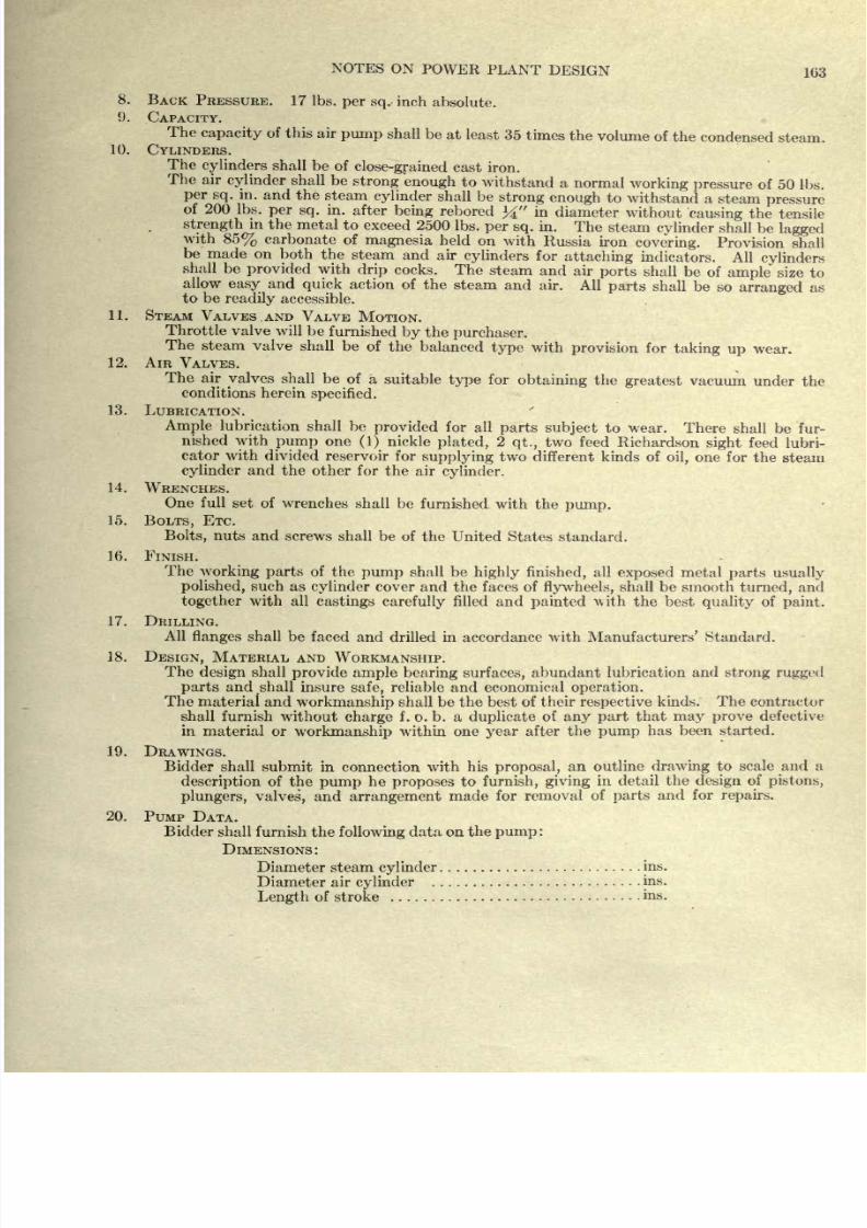
8/20/2019 notes on powerplant.pdf
http://slidepdf.com/reader/full/notes-on-powerplantpdf 169/202
NOTES ON
POWER
PLANT
DESIGN
163
8.
BACK
PRESSURE. 17
Ibs.
per
sq.
inch
absolute.
9.
CAPACITY.
The
capacity
of
this air
pump
shall
be
at
least
35
times
the
volume
of
the
condensed steam.
10.
CYLINDERS.
The
cylinders
shall be
of
close-grained
cast
iron.
The
air
cylinder
shall be
strong
enough
to
withstand a
normal
working
pressure
of
50
Ibs.
per
sq.
in.
and
the
steam
cylinder
shall be
strong
enough
to
withstand
a
steam
pressure
of
200
Ibs.
per
sq.
in.
after
being
rebored
%
in
diameter
without
causing
the
tensile
strength
in
the
metal
to
exceed
2500
Ibs.
per
sq.
in.
The
steam
cylinder
shall be
lagged
with
85%
carbonate
of
magnesia
held on
with
Russia
iron
covering.
Provision
shall
be made
on
both
the
steam
and air
cylinders
for
attaching
indicators.
All
cylinders
shall
be
provided
with
drip
cocks.
The
steam
and air
ports
shall
be
of
ample
size
to
allow
easy
and
quick
action
of
the
steam
and
air. All
parts
shall
be
so
arranged
as
to
be
readily
accessible.
11.
STEAM
VALVES
AND
VALVE
MOTION.
Throttle valve
will
be
furnished
by
the
purchaser.
The
steam
valve
shall be
of the
balanced
type
with
provision
for
taking
up
wear.
12.
AIR
VALVES.
The
air
valves
shall
be
of
a
suitable
type
for
obtaining the
greatest
vacuum
under
the
conditions herein
specified.
13.
LUBRICATION.
Ample
lubrication
shall
be
provided
for
all
parts
subject
to wear.
There
shall
be
fur-
nished with
pump
one
(1)
nickle
plated,
2
qt.,
two feed
Richardson
sight
feed lubri-
cator
with
divided
reservoir
for
supplying
two
different kinds of
oil,
one
for
the steam
cylinder
and
the other
for the
air
cylinder.
14.
WRENCHES.
One
full
set of
wrenches
shall
be
furnished with the
pump.
15.
BOLTS,
ETC.
Bolts,
nuts
and
screws
shall be
of
the United
States standard.
16.
FINISH.
The
working
parts
of
the
pump
shall
be
highly
finished,
all
exposed metal
parts usually
polished,
such
as
cylinder
cover and
the
faces
of
flywheels,
shall be smooth
turned,
and
together
with all
castings
carefully
filled
and
painted
\\ith
the
best
quality
of
paint.
17.
DRILLING.
All
flanges
shall
be faced
and drilled
in accordance
with
Manufacturers'
Standard.
18.
DESIGN,
MATERIAL
AND
WORKMANSHIP.
The
design
shall
provide
ample
bearing
surfaces,
abundant
lubrication
and
strong rugged
parts
and
shall
insure
safe,
reliable and economical
operation.
The
material
and
workmanship
shall
be the best of
their
respective
kinds.
The
contractor
shall
furnish
without
charge
f .
o.
b. a
duplicate
of
any
part
that
may
prove
defective
in
material or
workmanship
within
one
year
after the
pump
has been
started.
19.
DRAWINGS.
Bidder
shall
submit
in
connection
with his
proposal,
an
outline
drawing
to scale
and
n
description
of the
pump
he
proposes
to
furnish,
giving
in detail
the
design
of
pistons,
plungers, valves,
and
arrangement
made
for removal
of
parts
and for
repairs.
20.
PUMP
DATA.
Bidder shall
furnish
the
following
data on the
pump
:
DIMENSIONS:
Diameter
steam
cylinder
ins.
Diameter
air
cylinder
ins.
Length
of
stroke
ins.
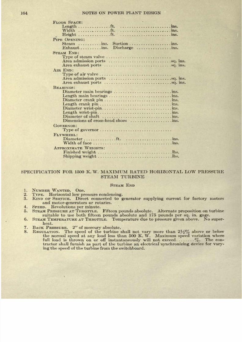
8/20/2019 notes on powerplant.pdf
http://slidepdf.com/reader/full/notes-on-powerplantpdf 170/202
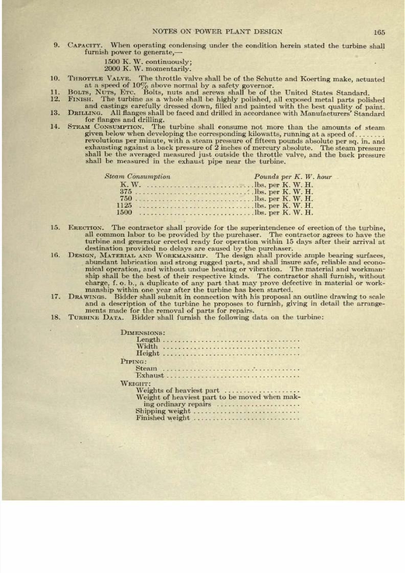
8/20/2019 notes on powerplant.pdf
http://slidepdf.com/reader/full/notes-on-powerplantpdf 171/202
NOTES
ON
POWER
PLANT DESIGN
165
9.
CAPACITY. When
operating
condensing
under
the
condition
herein
stated the
turbine
shall
furnish
power
to
generate,
1500 K.
W.
continuously;
2000
K.
W.
momentarily.
10. THROTTLE
VALVE. The
throttle
valve
shall
be
of
the
Schutte
and
Koerting
make,
actuated
at
a
speed
of
10%
above
normal
by
a
safety
governor.
11.
BOLTS,
NUTS,
ETC.
Bolts,
nuts
and
screws shall be
of the
United
States
Standard.
12. FINISH. The
turbine
as
a
whole
shall
be
highly
polished,
all
exposed
metal
parts
polished
and
castings
carefully
dressed
down,
filled
and
painted
with the
best
quality
of
paint.
13.
DRILLING.
All
flanges
shall
be
faced
and drilled in
accordance with
Manufacturers'
Standard
for
flanges
and
drilling.
14. STEAM
CONSUMPTION. The
turbine
shall
consume
not
more
than
the
amounts
of
steam
given
below
when
developing
the
corresponding kilowatts,
running
at a
speed
of
revolutions
per
minute,
with a steam
pressure
of
fifteen
pounds
absolute
per
sq.
in. and
exhausting against
a back
pressure
of
2
inches
of
mercury
absolute.
The steam
pressure
shall
be
the
averaged
measured
just
outside
the
throttle
valve,
and the
back
pressure
shall be
measured
in
the
exhaust
pipe
near the
turbine.
Steam
Consumption
Pounds
per
K.
W.
hour
K.
W
Ibs.
per
K. W. H.
375
'. .Ibs.
per
K.
W.
H.
750
Ibs.
per
K.
W.
H.
1125
Ibs.
per
K.
W.
H.
1500
Ibs.
per
K. W.
H.
15.
ERECTION. The
contractor
shall
provide
for
the
superintendence
of
erection of
the
turbine,
all
common
labor
to
be
provided by
the
purchaser.
The
contractor
agrees
to
have
the
turbine
and
generator
erected
ready
for
operation
within 15
days
after their
arrival
at
destination
provided
no
delays
are
caused
by
the
purchaser.
16.
DESIGN,
MATERIAL AND
WORKMANSHIP.
The
design
shall
provide ample
bearing surfaces,
abundant
lubrication and
strong
rugged
parts,
and
shall
insure
safe,
reliable
and econo-
mical
operation,
and
without
undue
heating
or
vibration.
The material
and workman-
ship
shall be
the
best of
their
respective
kinds. The
contractor shall
furnish,
without
charge,
f.
o.
b.,
a
duplicate
of
any
part
that
may
prove
defective
in
material or
work-
manship
within
one
year
after
the turbine
has
been
started.
17. DRAWINGS.
Bidder
shall
submit in connection
with
his
proposal
an
outline
drawing
to scale
and a
description
of
the
turbine
he
proposes
to
furnish, giving
in
detail the
arrange-
ments made for
the
removal
of
parts
for
repairs.
18.
TURBINE
DATA.
Bidder
shall
furnish the
following
data
on the turbine:
DIMENSIONS
:
Length
Width
Height
PIPING:
Steam
*
Exhaust
WEIGHT:
Weights
of
heaviest
part
Weight
of
heaviest
part
to
be moved
when
mak-
ing
ordinary
repairs
Shipping
weight
Finished
weight
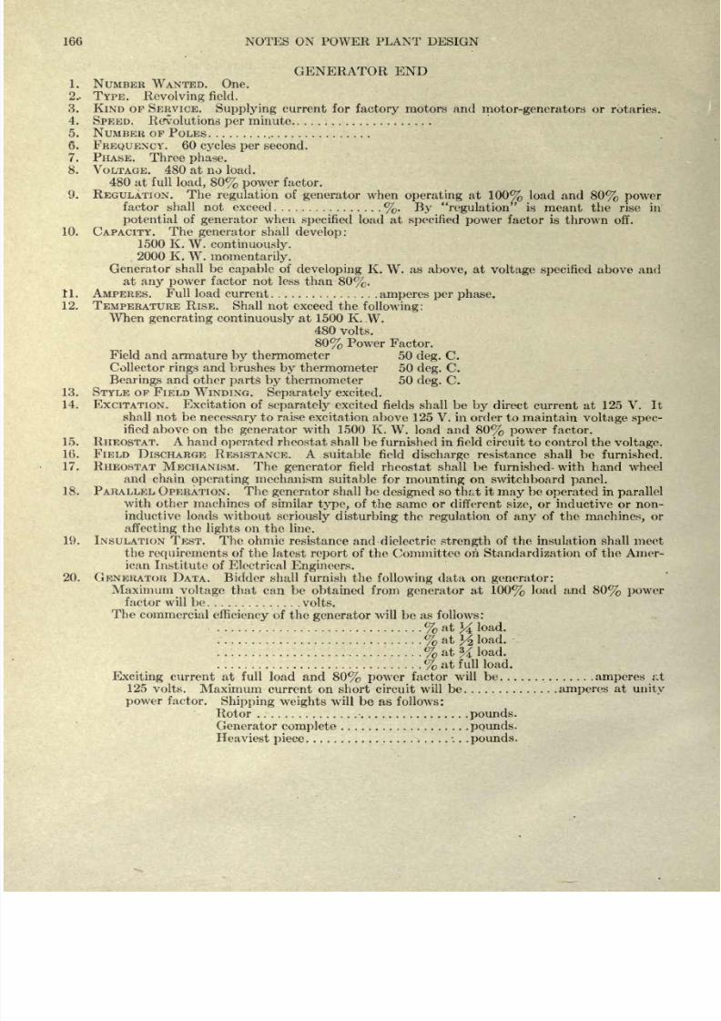
8/20/2019 notes on powerplant.pdf
http://slidepdf.com/reader/full/notes-on-powerplantpdf 172/202
166
NOTES ON POWER
PLANT
DESIGN
GENERATOR END
1. NUMBER
WANTED.
One.
2.-
TYPE.
Revolving
field.
3.
KIND
OF
SERVICE.
Supplying
current
for
factory
motors
and
motor-generators
or
rotaries.
4.
SPEED.
Revolutions
per
minute
5.
NUMBER
OF
POLES
6.
FREQUENCY.
60
cycles
per
second.
7.
PHASE.
Three
phase.
8.
VOLTAGE.
480 at
no load.
480
at
full
load, 80%
power
factor.
9.
REGULATION.
The
regulation
of
generator
when
operating
at
100%
load
and
80%
power
factor
shall not exceed
%. By
regulation
is
meant
the
rise
in
potential
of
generator
when
specified
load
at
specified
power
factor
is
thrown
off.
10.
CAPACITY. The
generator
shall
develop:
1500 K.
W.
continuously.
2000
K.
W.
momentarily.
Generator
shall be
capable
of
developing
K.
W.
as
above,
at
voltage
specified
above
and
at
any power
factor
not
less
than
80%.
11.
AMPERES.
Full load
current
amperes per
phase.
12.
TEMPERATURE
RISE.
Shall
not exceed
the
following:
When
generating
continuously
at
1500
K.
W.
480
volts.
80%
Power Factor.
Field
and
armature
by
thermometer
50
deg.
C.
Collector
rings
and brushes
by
thermometer 50
deg.
C.
Bearings
and
other
parts by
thermometer
50
deg.
C.
13.
STYLE OF FIELD
WINDING.
Separately
excited.
14. EXCITATION.
Excitation
of
separately
excited fields
shall
be
by
direct current
at
125
V.
It
shall
not
be
necessary
to
raise
excitation
above 125
V. in order
to
maintain
voltage
spec-
ified
above
on the
generator
with 1500
K.
W.
load
and
80%
power
factor.
15.
RHEOSTAT.
A hand
operated
rheostat shall
be furnished in field
circuit
to
control
the
voltage.
16.
FIELD
DISCHARGE RESISTANCE. A
suitable
field
discharge
resistance
shall
be
furnished.
17. RHEOSTAT
MECHANISM. The
generator
field
rheostat
shall
be
furnished- with hand
wheel
and
chain
operating
mechanism
suitable
for
mounting
on switchboard
panel.
18. PARALLEL
OPERATION. The
generator
shall
be
designed
so
that
it
may
be
operated
in
parallel
with other machines
of similar
type,
of
the same
or different
size,
or
inductive or
non-
inductive loads
without
seriously
disturbing
the
regulation
of
any
of
the
machines,
or
affecting
the
lights
on
the
line.
19.
INSULATION
TEST. The
ohmic resistance and dielectric
strength
of the
insulation
shall meet
the
requirements
of
the latest
report
of
the
Committee on
Standardization
of
the Amer-
ican
Institute
of
Electrical
Engineers.
20.
GENERATOR
DATA.
Bidder
shall furnish
the
following
data
on
generator:
Maximum
voltage
that
can
be obtained
from
generator
at
100%
load and
80%
power
factor
will
be
volts.
The
commercial
efficiency
of
the
generator
will
be
as follows:
%
at
%
load.
%
at
^
load.
%
at
%
load.
%
at
full
load.
Exciting
current
at
full
load
and
80%
power
factor
will
be
amperes
at
125
volts.
Maximum
current
on
short
circuit
will be
.amperes
at
unity
power
factor.
Shipping
weights
will
be
as
follows:
Rotor
pounds.
Generator
complete
pounds.
Heaviest
piece
.
.
.
pounds.
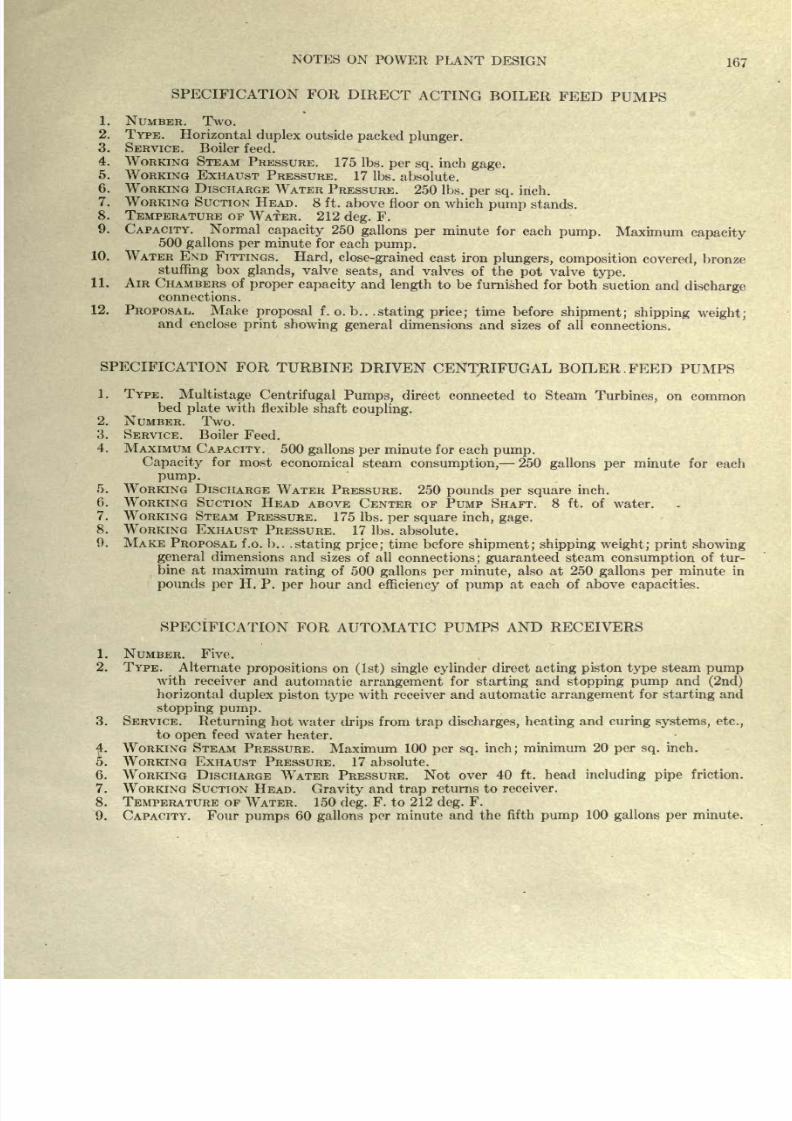
8/20/2019 notes on powerplant.pdf
http://slidepdf.com/reader/full/notes-on-powerplantpdf 173/202
NOTES
ON
POWER
PLANT
DESIGN
167
SPECIFICATION
FOR
DIRECT
ACTING
BOILER
FEED
PUMPS
1.
NUMBER.
Two.
2.
TYPE.
Horizontal
duplex
outside
packed
plunger.
3.
SERVICE. Boiler
feed.
4.
WORKING STEAM
PRESSURE.
175
Ibs.
per
sq.
inch
gage.
5.
WORKING
EXHAUST
PRESSURE.
17 Ibs.
absolute.
6.
WORKING DISCHARGE
WATER
PRESSURE.
250
Ibs.
per
sq.
inch.
7.
WORKING SUCTION
HEAD.
8
ft.
above
floor
on which
pump
stands.
8.
TEMPERATURE
OF
WATER. 212
deg.
F.
9.
CAPACITY.
Normal
capacity
250
gallons
per
minute
for each
pump.
Maximum
capacity
500
gallons
per
minute
for
each
pump.
10. WATER END
FITTINGS.
Hard,
close-grained
cast
iron
plungers, composition
covered,
bronze
stuffing
box
glands,
valve
seats,
and valves
of
the
pot
valve
type.
11.
AIR
CHAMBERS
of
proper
capacity
and
length
to
be
furnished for
both
suction
and
discharge
connections.
12. PROPOSAL.
Make
proposal
f. o.
b..
.stating price;
time
before
shipment;
shipping
weight;
and
enclose
showing
general
dimensions and
sizes
of
all
connections.
SPECIFICATION
FOR
TURBINE
DRIVEN
CENTRIFUGAL BOILER.
FEED
PUMPS
1.
TYPE.
Multistage
Centrifugal
Pumps,
direct connected
to
Steam
Turbines,
on
common
bed
plate
with
flexible
shaft
coupling.
2.
NUMBER.
Two.
3.
SERVICE. Boiler
Feed.
4.
MAXIMUM
CAPACITY.
500
gallons
per
minute for each
pump.
Capacity
for
most
economical
steam
consumption,
250
gallons
per
minute
for each
pump.
5. WORKING
DISCHARGE
WATER
PRESSURE.
250
pounds
per
square
inch.
6.
WORKING
SUCTION
HEAD
ABOVE
CENTER
OP
PUMP
SHAFT.
8 ft.
of
water.
7.
WORKING
STEAM
PRESSURE.
175
Ibs.
per
square
inch,
gage.
8.
WORKING
EXHAUST
PRESSURE. 17
Ibs.
absolute.
9.
MAKE
PROPOSAL
f.o.
b..
.stating price;
time before
shipment;
shipping
weight; print
showing
general
dimensions
and
sizes of all
connections;
guaranteed
steam
consumption
of tur-
bine at
maximum
rating
of 500
gallons
per
minute,
also
at
250
gallons
per
minute
in
pounds
per
H. P.
per
hour
and
efficiency
of
pump
at
each
of
above
capacities.
SPECIFICATION
FOR
AUTOMATIC
PUMPS
AND
RECEIVERS
1.
NUMBER. Five.
2.
TYPE.
Alternate
propositions
on
(1st)
single cylinder
direct
acting piston type
steam
pump
with receiver
and
automatic
arrangement
for
starting
and
stopping pump
and
(2nd)
horizontal
duplex
piston
type
with
receiver
and
automatic
arrangement
for
starting
and
stopping
pump.
3.
SERVICE.
Returning
hot
water
drips
from
trap
discharges,
heating
and
curing systems,
etc.,
to
open
feed
water
heater.
4. WORKING
STEAM
PRESSURE.
Maximum
100
per
sq.
inch;
minimum
20
per
sq.
inch.
5.
WORKING EXHAUST
PRESSURE.
17
absolute.
6.
WORKING
DISCHARGE
WATER PRESSURE.
Not over
40
ft.
head
including
pipe
friction.
7. WORKING
SUCTION
HEAD.
Gravity
and
trap
returns to
receiver.
8.
TEMPERATURE OF
WATER.
150
deg.
F. to
212
deg.
F.
9. CAPACITY. Four
pumps
60
gallons
per
minute and
the fifth
pump
100
gallons
per
minute.
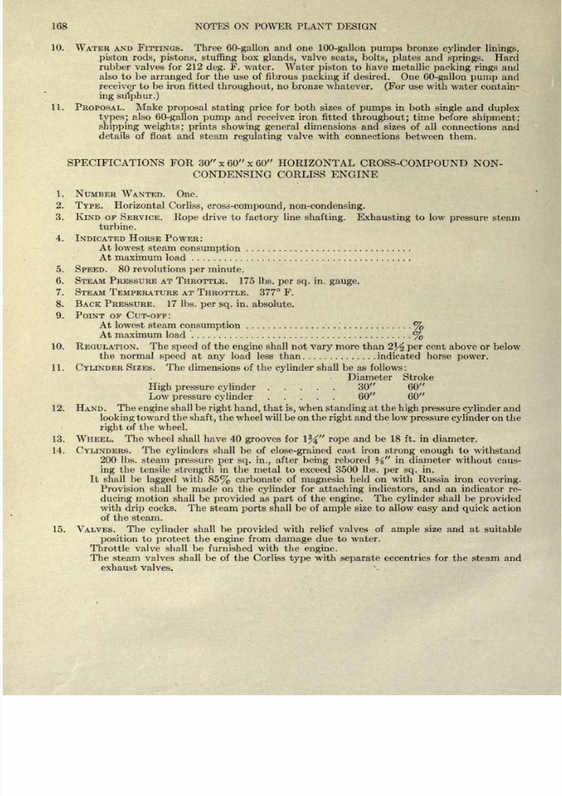
8/20/2019 notes on powerplant.pdf
http://slidepdf.com/reader/full/notes-on-powerplantpdf 174/202
168 NOTES
ON
POWER
PLANT
DESIGN
10.
WATER
AND
FITTINGS.
Three
60-gallon
and
one
100-gallon
pumps
bronze
cylinder linings,
piston rods,
pistons,
stuffing
box
glands,
valve
seats, bolts,
plates
and
springs.
Hard
rubber
valves
for 212
deg.
F.
water.
Water
piston
to
have metallic
packing
rings
and
also
to
be
arranged
for
the use of
fibrous
packing
if
desired.
One
60-gallon
pump
and
receiver
to
be
iron
fitted
throughout,
no
bronze
whatever.
(For
use with
water
contain-
ing sulphur.)
11. PROPOSAL.
Make
proposal
stating price
for
both
sizes
of
pumps
in both
single
and
duplex
types;
also
60-gallon
pump
and receiver:
iron
fitted
throughout;
time
before
shipment;
shipping
weights;
prints showing general
dimensions
and
sizes of all
connections and
details
of float and
steam
regulating
valve
with connections
between
them.
SPECIFICATIONS
FOR
30
x 60
x
60
HORIZONTAL
CROSS-COMPOUND
NON-
CONDENSING CORLISS ENGINE
1.
NUMBER
WANTED.
One.
2.
TYPE. Horizontal
Corliss,
cross-compound,
non-condensing.
3.
KIND
OF
SERVICE.
Rope
drive
to
factory
line
shafting.
Exhausting
to
low
pressure
steam
turbine.
4.
INDICATED
HORSE
POWER:
At
lowest
steam
consumption
At maximum
load
5. SPEED. 80 revolutions
per
minute.
6.
STEAM
PRESSURE AT
THROTTLE.
175
Ibs.
per
sq.
in.
gauge.
7.
STEAM
TEMPERATURE AT
THROTTLE.
377 F.
8.
BACK
PRESSURE. 17
Ibs.
per
sq.
in.
absolute.
9.
POINT OF CUT-OFF:
At
lowest steam
consumption %
At
maximum
load
%
10.
REGULATION. The
speed
of
the
engine
shall
not
vary
more
than
2J^ per
cent above or
below
the
normal
speed
at
any
load
less than
indicated horse
power.
11.
CYLINDER
SIZES.
The
dimensions
of
the
cylinder
shall
be
as
follows
:
Diameter Stroke
High
pressure cylinder
30
60
Low
pressure
cylinder
60 60
12.
HAND.
The
engine
shall
be
right
hand,
that
is,
when
standing
at the
high
pressure
cylinder
and
looking
toward
the
shaft,
the wheel will
be on
the
right
and
the
low
pressure
cylinder
on
the
right
of
the
wheel.
13.
WHEEL.
The wheel
shall have 40
grooves
for
1%
rope
and
be
18
ft.
in
diameter.
14.
CYLINDERS.
The
cylinders
shall
be
of
close-grained
cast iron
strong
enough
to
withstand
200
Ibs.
steam
pressure
per
sq. in.,
after
being
rebored
Z
A
in
diameter
without
caus-
ing
the
tensile
strength
in
the
metal to exceed
3500 Ibs.
per
sq.
in.
It
shall be
lagged
with
85%
carbonate
of
magnesia
held on with
Russia iron
covering.
Provision shall be
made
on
the
cylinder
for
attaching
indicators,
and
an
indicator
re-
ducing
motion
shall
be
provided
as
part
of the
engine.
The
cylinder
shall be
provided
with
drip
cocks.
The steam
ports
shall
be
of
ample
size to allow
easy
and
quick
action
of
the
steam.
15.
VALVES.
The
cylinder
shall be
provided
with
relief valves
of
ample
size and
at
suitable
position
to
protect
the
engine
from
damage
due
to water.
Throttle
valve
shall be furnished
with the
engine.
The
steam
valves shall
be
of
the Corliss
type
with
separate
eccentrics for the steam and
exhaust
valves.
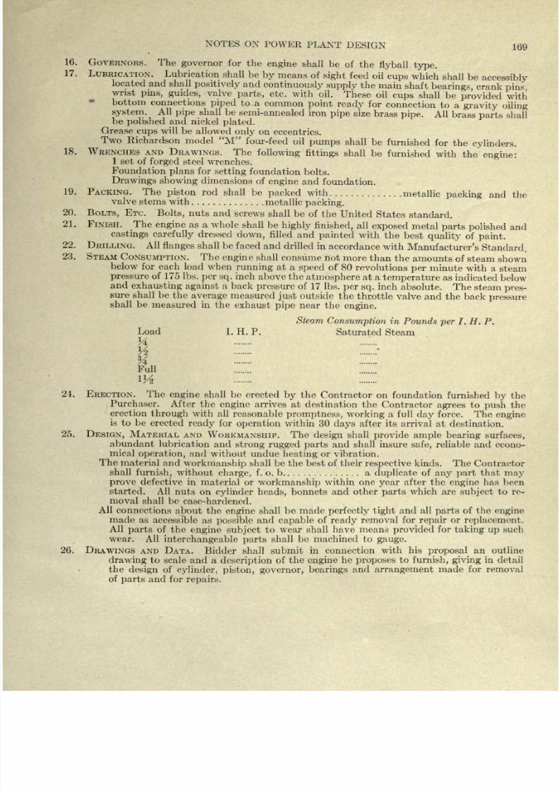
8/20/2019 notes on powerplant.pdf
http://slidepdf.com/reader/full/notes-on-powerplantpdf 175/202
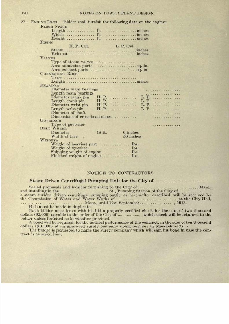
8/20/2019 notes on powerplant.pdf
http://slidepdf.com/reader/full/notes-on-powerplantpdf 176/202
170
NOTES ON POWER PLANT
DESIGN
27.
ENGINE
DATA.
Bidder
shall furnish the
following
data on
the
engine:
FLOOR
SPACE
Length
ft inches
\Yidth
ft.
inches
Height
ft inches
PIPING
H.
P.
Cyl.
L.
P.
Cyl.
Steam
inches
Exhaust
inches
VALVES
Type
of steam valves
Area admission
ports sq.
in.
Area exhaust
ports
.
. .
.sq.
in.
CONNECTING
RODS
Type
Length
inches
BEARINGS
Diameter main
bearings
Length
main
bearings
Diameter
crank
pin
H.
P. .
,
L.
P
Length
crank
pin
H.
P
L.
P
Diameter wrist
pin
H.
P L. P
Length
wrist
pin
H.
P
L.
P
Diameter of
shaft
Dimensions of
cross-head
shoes
GOVERNOR
Type
of
governor
BELT
WHEEL
Diameter
18
ft.
inches
Width of
face
.
56 inches
WEIGHTS
Weight
of
heaviest
part
Ibs.
Weight
of
fly-wheel
Ibs.
Shipping
weight
of
engine
Ibs.
Finished
weight
of
engine
Ibs.
NOTICE TO CONTRACTORS
Steam
Driven
Centrifugal
Pumping
Unit
for
the
City
of.
Sealed
proposals
and
bids for
furnishing
to
the
City
of
Mass.,
and
installing
in
the
St., Pumping
Station of
the
City
of
a
steam
turbine
driven
centrifugal
pumping
outfit,
as
hereinafter
described,
will
be
received
by
the
Commission of Water and
Water
Works
of at
the
City
Hall,
Mass.,
until
12M,
September
,
1913.
Bids
must
be
made
in
duplicate.
Each
bidder
must leave
with his
bid a
properly
certified
check
for the
sum
of
two
thousand
dollars
($2,000)
payable
to
the
order of
the
City
of
,
which
check
will be
returned
to
the
bidder
unless
forfeited
as
hereinafter
provided.
A
bond
will
be
required,
for
the
faithful
performance
of
the
contract,
in the sum of ten
thousand
dollars
($10,000)
of
an
approved surety company
doing
business in Massachusetts.
The
bidder
is
requested
to
name the
surety
company
which
will
sign
his
bond
in
case
the con-
tract
is
awarded
him.
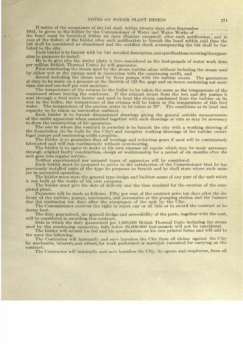
8/20/2019 notes on powerplant.pdf
http://slidepdf.com/reader/full/notes-on-powerplantpdf 177/202
NOTES
ON
POWER
PLANT
DESIGN
171
If
notice of the
acceptance
of
the
bid
shall,
within
twenty days
after
September
,
1913,
be
given
to the
bidder
by
the
Commissioner
of
Water
and
Water
Works
of
*. * ,
the bond
must
be
furnished
within six
days
(Sunday
excepted)
after
such
notification;
and
in
case of
the
failure of the
bidder
after
such
notification to
furnish
the
bond
within
said
time
the
bid
shall be
considered as
abandoned
and
the
certified
check
accompanying
the
bid shall
be
for-
feited
to
the
city.
Each
bidder
is
to
furnish
with
his
bid
detailed
description
and
specifications
covering
the
appar-
atus
he
purposes
to
install.
He is
to
give
also
the
duties
(duty
is
here
considered
as
the
foot-pounds
of
water work
done
per
million British
Thermal
Units)
he
will
guarantee.
First
considering
the
steam
used
by
the
steam
turbine
alone
without
including
the
steam
used
by
either
wet
or
dry
pumps
used in
connection
with
the
condensing
outfit,
and
Second
including
the
steam
used
by
these
pumps
with
the
turbine
steam.
The
guarantees
of
duty
to be
made
on
a
pressure
at
the
throttle
of 125
Ibs.
gage
and
on
steam
containing
not
more
than
one and
one-half
per
cent
moisture.
The
temperature
of
the
returns
to the
boiler to
be
taken
the same
as
the
temperature
of the
condensed steam
leaving
the
condenser.
If
the
exhaust steam
from the
wet
and
dry
pumps
is
sent
through
a feed
water
heater
and used
to
heat
the
steam
condensed from
the
turbine
on
its
way
to
the
boiler,
the
temperature
of
the returns
will
be
taken
as
the
temperature
of
this feed
water.
The
temperature
of
the
suction
water
to
be
taken
at
70.
The
conditions as
to
head
and
capacity
to be taken as
hereinafter
outlined.
Each
^
bidder
is
to
furnish
dimensioned
drawings
giving
the
general
outside measurements
of the entire
apparatus
when
assembled
together
with such
drawings
or
cuts
as
may
be
necessary
to
show the
construction
of
his
apparatus.
The one
to whom
the
contract
is
awarded is
to
furnish the
city
with
a
working
drawing
of
the
foundation
(to
be
built
by
the
City)
and
complete
working
drawings
of
the
turbine centri-
fugal
pumps
and
condensing
outfit
complete.
The
bidder
is
to
guarantee
that all
bearings
and
reduction
gears
if
used
will be
continuously
lubricated
and
will
run
continuously
without
over-heating.
The bidder
is to
agree
to
make at his
own
expense
all
repairs
which
may
be
made
necessary
through
original
faulty
construction,
design
or
workmanship
for a
period
of six months
after the
unit
goes
into
regular
service.
Neither
experimental
nor unusual types
of
apparatus
will
be
considered.
Each
bidder
must
be
prepared
to
prove
to the satisfaction
of the
Commissioner
that
he
has
previously
installed
units
of
the
type
he
purposes
to
furnish
and
he
shall
state
where such
units
are in
successful
operation.
The bidder
must
state
the
general type
design
and builders
name
of
any
part
of the
unit which
is
not
built
at
the
works of
his
own
company.
The
bidder must
give
the
date of
delivery
and
the
time
required
for
the
erection
of
the
com-
pleted
plant.
Payments
will
be
made
as
follows
:
Fifty
per
cent of
the
contract
price
ten
days
after
the
de-
livery
of
the
turbine,
pumps,
condensers,
and accessories
at
the
pumping
station
and the
balance
due
the contractor
ten
days
after the
acceptance
of
the
unit
by
the
City.
The
Commissioner
reserves
the
right
to
reject
any
or
all
bids or to
award the
contract
as
he
deems
best.
The
duty
guaranteed,
the
general
design
and
accessibility
of
the
parts,
together
with
the
cost,
will be
considered
in
awarding
this
contract.
Bids
in
which
the
duty
guaranteed
per
1,000,000
British
Thermal
Units
including
the
steam
used
by
the
condensing apparatus,
falls
below
92,000,000
foot-pounds
will
not
be considered.
The
bidder
will
submit
his bid and his
specifications
on
his own
printed
forms
and
will
add
to
the
same
the
following:
The
Contractor
will
indemnify
and save
harmless
the
City
from
all
claims
against
the
City
by
mechanics, laborers,
and
others,
for
work
performed
or
materials
furnished
for
carrying
on
the
contract.
The
Contractor
will
indemnify
and save
harmless
the
City,
its
agents
and
employees,
from
all
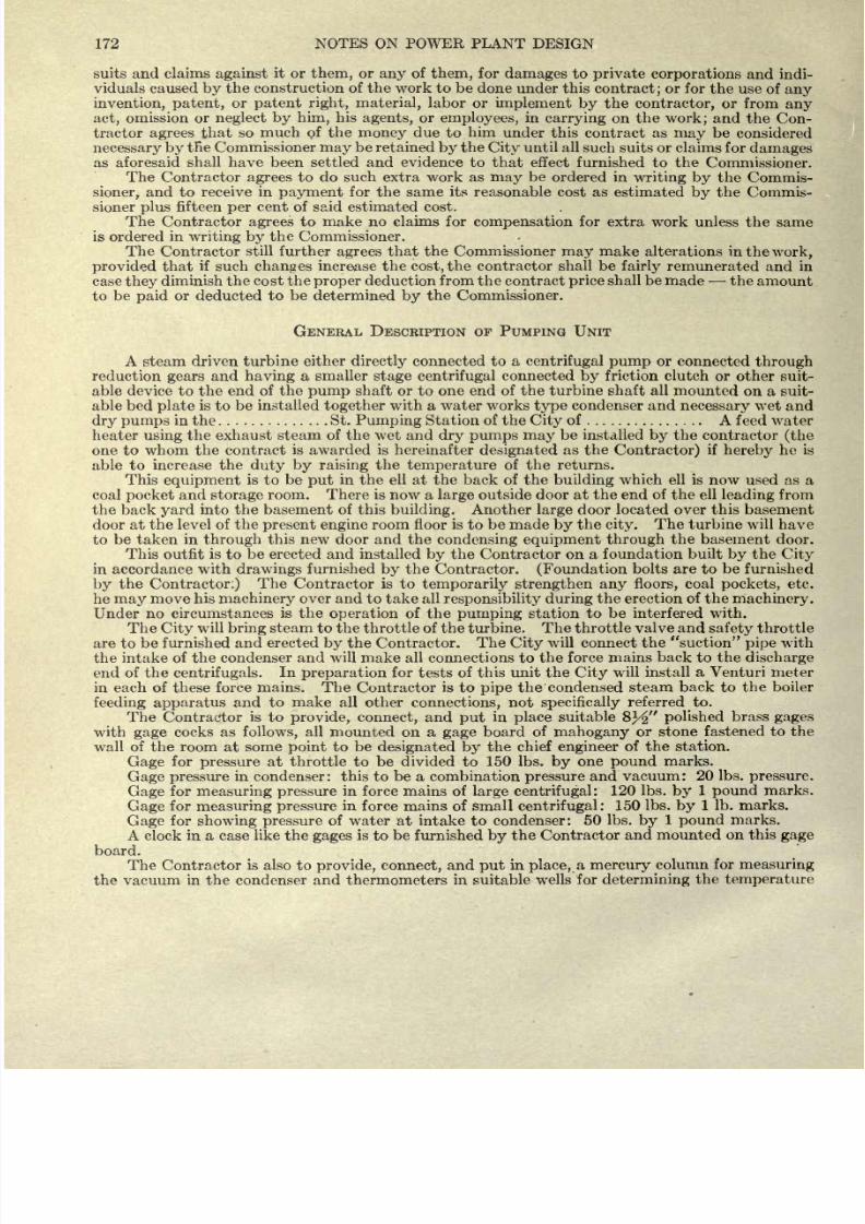
8/20/2019 notes on powerplant.pdf
http://slidepdf.com/reader/full/notes-on-powerplantpdf 178/202
172
NOTES
ON POWER
PLANT
DESIGN
suits and
claims
against
it or
them,
or
any
of
them,
for
damages
to
private corporations
and indi-
viduals caused
by
the
construction of the work to
be
done under
this
contract;
or
for the use
of
any
invention,
patent,
or
patent
right,
material,
labor
or
implement
by
the
contractor,
or from
any
act,
omission
or
neglect by
him,
his
agents,
or
employees,
in
carrying
on
the
work;
and
the Con-
tractor
agrees
that
so
much
of
the
money
due
to
him
under this
contract
as
may
be
considered
necessary
by
tfie
Commissioner
may
be
retained
by
the
City
until all such
suits
or
claims for
damages
as aforesaid
shall have been
settled
and evidence
to
that
effect
furnished
to the
Commissioner.
The
Contractor
agrees
to
do
such
extra
work
as
may
be
ordered
in
writing
by
the
Commis-
sioner,
and
to
receive
in
payment
for
the
same
its
reasonable
cost
as
estimated
by
the
Commis-
sioner
plus
fifteen
per
cent
of said
estimated cost.
The
Contractor
agrees
to
make
no
claims for
compensation
for
extra
work unless
the
same
is ordered
in
writing by
the
Commissioner.
The Contractor
still
further
agrees
that the Commissioner
may
make
alterations
in
the
work,
provided
that
if
such
changes
increase
the
cost,
the
contractor
shall be
fairly
remunerated and
in
case
they
diminish
the cost the
proper
deduction
from
the contract
price
shall
be
made
the
amount
to
be
paid
or
deducted
to be
determined
by
the
Commissioner.
GENERAL
DESCRIPTION
OF PUMPING UNIT
A steam
driven
turbine either
directly
connected
to
a
centrifugal
pump
or
connected
through
reduction
gears
and
having
a
smaller
stage
centrifugal
connected
by
friction
clutch or
other
suit-
able
device
to
the
end
of
the
pump
shaft
or
to one
end of the turbine
shaft
all
mounted on a suit-
able
bed
plate
is
to
be
installed
together
with a water
works
type
condenser
and
necessary
wet and
dry
pumps
in
the
St.
Pumping
Station
of
the
City
of
A
feed
water
heater
using
the
exhaust
steam
of the wet and
dry
pumps
may
be installed
by
the
contractor
(the
one
to
whom
the
contract
is
awarded
is hereinafter
designated
as
the
Contractor)
if
hereby
he
is
able
to
increase the
duty
by
raising
the
temperature
of
the
returns.
This
equipment
is
to
be
put
in
the ell at the back
of
the
building
which
ell is
now
used as
a
coal
and
storage
room.
There
is now a
large
outside
door at the end
of
the
ell
leading
from
the back
yard
into
the basement of this
building.
Another
large
door
located
over
this
basement
door at
the
level of
the
present
engine
room
floor
is
to
be
made
by
the
city.
The
turbine
will
have
to be
taken
in
through
this new door and
the
condensing
equipment
through
the basement
door.
This
outfit
is
to
be erected
and
installed
by
the
Contractor
on
a foundation built
by
the
City
in
accordance
with drawings
furnished
by
the
Contractor.
(Foundation
bolts
are to
be
furnished
by
the
Contractor:)
The
Contractor is
to
temporarily
strengthen any
floors,
coal
pockets,
etc.
he
may
move
his
machinery
over
and to take
all
responsibility
during
the
erection
of
the
machinery.
Under
no circumstances
is
the
operation
of
the
pumping
station
to be
interfered
with.
The
City
will
bring
steam to
the
throttle of the
turbine.
The
throttle
valve
and
safety
throttle
are
to
be
furnished
and
erected
by
the Contractor.
The
City
will
connect the
suction
pipe
with
the
intake of
the
condenser
and
will make
all connections
to the
force mains back to
the
discharge
end of the
centrifugals.
In
preparation
for
tests
of
this
unit
the
City
will
install a
Venturi
meter
in
each
of
these
force
mains.
The
Contractor
is
to
pipe
the condensed
steam
back
to
the
boiler
feeding
apparatus
and
to make
all other
connections,
not
specifically
referred
to.
The
Contractor
is
to
provide,
connect,
and
put
in
place
suitable
&%
polished
brass
gages
with
gage
cocks
as
follows,
all mounted
on a
gage
board
of
mahogany
or stone fastened
to the
wall
of the
room
at
some
point
to be
designated by
the
chief
engineer
of
the
station.
Gage
for
pressure
at
throttle
to
be
divided to
150
Ibs.
by
one
pound
marks.
Gage
pressure
in condenser: this to be a
combination
pressure
and
vacuum:
20 Ibs.
pressure.
Gage
for
measuring
pressure
in force mains
of
large centrifugal:
120
Ibs.
by
1
pound
marks.
Gage
for
measuring
pressure
in
force
mains of small
centrifugal
: 150
Ibs.
by
1
Ib. marks.
Gage
for
showing pressure
of water
at
intake
to
condenser:
50
Ibs.
by
1
pound
marks.
A
clock
in a case
like
the
gages
is
to
be
furnished
by
the Contractor
and
mounted
on
this
gage
board.
The Contractor
is also to
provide,
connect,
and
put
in
place,
a
mercury
column
for
measuring
the
vacuum
in the
condenser and
thermometers
in
suitable
wells
for
determining
the
temperature
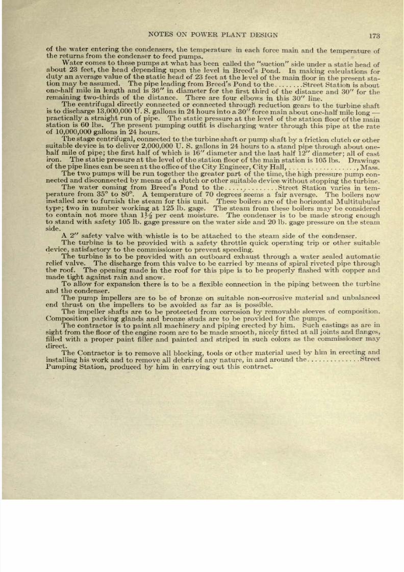
8/20/2019 notes on powerplant.pdf
http://slidepdf.com/reader/full/notes-on-powerplantpdf 179/202
NOTES
ON
POWER
PLANT
DESIGN
173
of
the
water
entering
the
condensers,
the
temperature
in each
force
main
and
the
temperature
of
the returns
from
the
condenser
to feed
pumps.
Water
comes
to these
pumps
at
what
has
been
called
the
suction
side
under a
static
head
of
about
23
feet,
the
head
depending
upon
the
level
in
Breed's
Pond.
In
making
calculations
for
duty
an
average
value
of
the
static head
of 23
feet
at
the level
of the
main
floor
in the
present
sta-
tion
may
be
assumed.
The
pipe
leading
from
Breed's
Pond
to the
Street
Station
is
about
one-half mile in
length
and
is
36 in
diameter
for
the
first third
of
the
distance
and
30
for
the
remaining
two-thirds
of
the
distance.
There
are
four
elbows in this 30
line.
The
centrifugal
directly
connected
or
connected
through
reduction
gears
to
the
turbine
shaft
is
to
discharge 13,000,000
U. S.
gallons
in
24
hours into
a 30
force
main
about
one-half
mile
long
-
practically
a
straight
run of
pipe.
The static
pressure
at
the level
of
the
station
floor of
the
main
station is 60 Ibs.
The
present
pumping
outfit
is
discharging
water
through
this
pipe
at
the
rate
of
10,000,000
gallons
in
24
hours.
The
stage
centrifugal,
connected
to
the
turbine
shaft
or
pump
shaft
by
a
friction clutch
or
other
suitable device
is, to
deliver
2,000,000
U.S.
gallons
in 24
hours
to a
stand
pipe
through
about
one-
half
mile
of
pipe;
the first half
of which
is
16
diameter
and
the
last
half
12
diameter;
all
of
cast
iron.
The
static
pressure
at
the
level
of
the
station floor
of
the
main
station
is
105
Ibs.
Drawings
of
the
pipe
lines can be
seen
at
the
office of
the
City
Engineer,
City Hall,
,
Mass.
The
two
pumps
will
be
run
together
the
greater
part
of
the
time,
the
high
pressure
pump
con-
nected
and
disconnected
by
means
of
a
clutch or other
suitable
device
without
stopping
the
turbine.
The
water
coming
from
Breed's
Pond to the
x
.
Street
Station
varies
in tem-
perature
from
35 to
80.
A
temperature
of
70
degrees
'seems
a
fair
average.
The
boilers now
installed are
to
furnish
the
steam
for
this
unit.
These
boilers are
of the
horizontal
Multitubular
type;
two
in
number
working
at
125
Ib.
gage.
The
steam
from
these
boilers
may
be
considered
to
contain not
more
than
1J^
per
cent
moisture. The condenser is
to be made
strong
enough
to
stand
with
safety
105
Ib.
gage pressure
on the
water
side and 20
Ib.
gage pressure
on
the steam
side.
A
2
safety
valve
with
whistle
is
to
be
attached to
the steam side
of
the
condenser.
The
turbine is
to
be
provided
with a
safety
throttle
quick operating trip
or
other suitable
device,
satisfactory
to
the
commissioner to
prevent
speeding.
The
turbine
is
to be
provided
with
an outboard exhaust
through
a
water sealed
automatic
relief
valve.
The
discharge
from
this
valve
to
be
carried
by
means
of
spiral
riveted
pipe
through
the
roof.
The
opening
made
in the roof
for
this
pipe
is
to
be
properly
flashed
with
copper
and
made
tight
against
rain
and
snow.
To
allow
for
expansion
there is
to
be
a
flexible
connection
in
the
piping
between the
turbine
and the
condenser.
The
pump
impellers
are
to
be
of bronze
on
suitable non-corrosive
material
and unbalanced
end
thrust
on
the
impellers
to
be avoided as
far
as
is
possible.
The
impeller
shafts are
to be
protected
from
corrosion
by
removable
sleeves
of
composition.
Composition
packing
glands
and
bronze
studs
are
to
be
provided
for the
pumps.
The
contractor
is
to
paint
all
machinery
and
piping
erected
by
him.
Such
castings
as are
in
sight
from the floor
of
the
engine
room
are
to
be
made
smooth,
nicely
fitted
at
all
joints
and
flanges,
filled
with
a
proper
paint
filler and
painted
and
striped
in such
colors
as
the
commissioner
may
direct.
The
Contractor
is
to
remove
all
blocking,
tools
or
other
material
used
by him
in
erecting
and
installing
his
work
and
to remove all debris of
any
nature,
in and
around
the
Street
Pumping Station,
produced
by
him
in
carrying
out
this
contract.
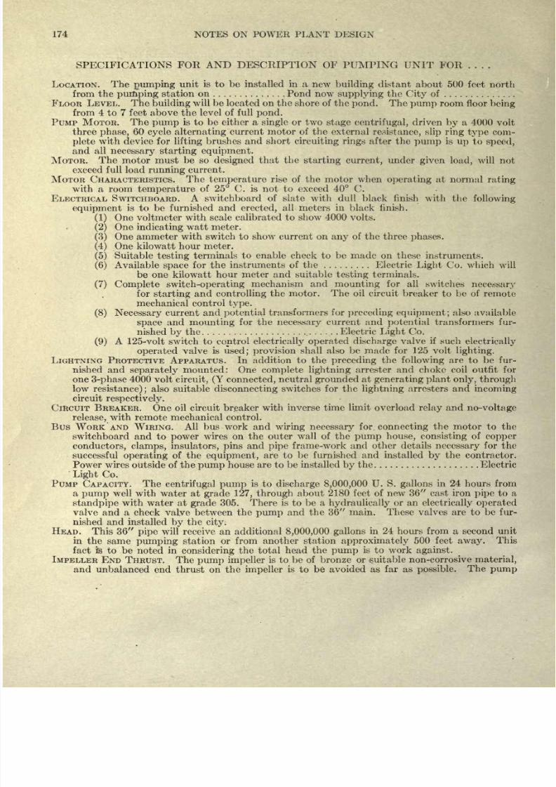
8/20/2019 notes on powerplant.pdf
http://slidepdf.com/reader/full/notes-on-powerplantpdf 180/202
174
NOTES ON POWER
PLANT
DESIGN
SPECIFICATIONS
FOR AND
DESCRIPTION
OF
PUMPING
UNIT
FOR
LOCATION.
The
pumping
unit
is to
be
installed
in a
new
building
distant
about
500
feet
north
from
the
pumping
station
on
Pond
now
supplying
the
City
of
FLOOR
LEVEL.
The
building
will
be
located
on
the
shore
of the
pond.
The
pump
room floor
being
from
4
to
7
feet
above
the
level
of full
pond.
PUMP
MOTOR.
The
pump
is
to
be
either
a
single or
two
stage
centrifugal,
driven
by
a
4000
volt
three
phase,
60
cycle
alternating
current motor
of the external
resistance,
slip
ring
type
com-
plete
with
device
for
lifting
brushes and short
circuiting
rings
after the
pump
is
up
to
speed,
and
all
necessary
starting
equipment.
MOTOR.
The
motor
must
be so
designed
that
the
starting current,
under
given
load,
will
not
exceed
full load
running
current.
MOTOR
CHARACTERISTICS.
The
temperature
rise
of the motor
when
operating
at normal
rating
with
a room
temperature
of
25
C. is not to
exceed
40
C.
ELECTRICAL SWITCHBOARD.
A switchboard
of slate
with
dull
black finish
with the
following
equipment
is
to
be
furnished
and
erected,
all
meters
in black
finish.
(1)
One voltmeter
with
scale
calibrated
to show
4000
volts.
(2)
One
indicating
watt
meter.
(3)
One ammeter with switch
to
show current
on
any
of the three
phases.
(4)
One
kilowatt
hour
meter.
(5)
Suitable
testing
terminals
to
enable
check to
be
made
on
these
instruments.
(6)
Available
space
for
the
instruments
of
the
Electric
Light
Co. which
will
be one
kilowatt
hour
meter and suitable
testing
terminals.
(7)
Complete
switch-operating
mechanism
and
mounting
for
all
switches
necessary
for
starting
and
controlling
the motor.
The oil
circuit
breaker
to
be
of
remote
mechanical
control
type.
(8)
Necessary
current
and
potential
transformers
for
preceding
equipment;
also
available
space
and
mounting
for
the
necessary
current
and
potential
transformers fur-
nished
by
the
Electric
Light
Co.
(9)
A
125-volt switch
to
control
electrically
operated discharge
valve
if
such
electrically
operated
valve is
used;
provision
shall
also
be
made
for
125 volt
lighting.
LIGHTNING
PROTECTIVE APPARATUS.
In
addition
to the
preceding
the
following
are
to be
fur-
nished and
separately
mounted:
One
complete lightning
arrester
and choke
coil outfit
for
one
3-phase
4000
volt
circuit,
(Y connected,
neutral
grounded
at
generating
plant
only,
through
low
resistance);
also
suitable
disconnecting
switches
for
the
lightning
arresters
and
incoming
circuit
respectively.
CIRCUIT
BREAKER.
One
oil
circuit
breaker
with inverse
time
limit
overload
relay
and
no-voltage
release,
with remote
mechanical
control.
Bus
WORK
AND
WIRING.
All
bus work
and
wiring
necessary
for.
connecting
the
motor to
the
switchboard and
to
power
wires
on
the
outer
wall of
the
pump
house,
consisting
of
copper
conductors,
clamps,
insulators, pins
and
pipe
frame-work and
other
details
necessary
for
the
successful
operating
of
the
equipment,
are to
be
furnished
and
installed
by
the
contractor.
Power
wires
outside
of
the
pump
house
are
to be installed
by
the Electric
Light
Co.
PUMP CAPACITY. The
centrifugal
pump
is
to
discharge 8,000,000
U.
S.
gallons
in 24
hours from
a
pump
well
with water at
grade
127,
through
about 2180 feet of
new
36
cast
iron
pipe
to
a
standpipe
with water
at
grade
305.
There is to
be a
hydraulically
or
an
electrically operated
valve
and
a check
valve
between
the
pump
and the
36 main.
These valves
are
to
be
fur-
nished and
installed
by
the
city.
HEAD.
This
36
pipe
will
receive an additional
8,000,000
gallons
in 24
hours from a second
unit
in
the
same
pumping
station
or from another
station
approximately
500 feet
away.
This
fact fe
to
be
noted
in
considering
the
total
head
the
pump
is
to work
against.
IMPELLER END
THRUST.
The
pump
impeller
is
to
be of
bronze
or
suitable non-corrosive
material,
and
unbalanced
end
thrust on
the
impeller
is
to
be
avoided
as
far as
possible.
The
pump
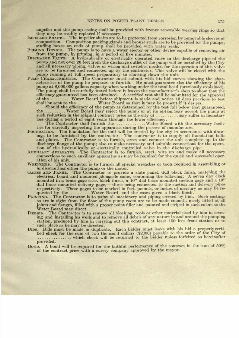
8/20/2019 notes on powerplant.pdf
http://slidepdf.com/reader/full/notes-on-powerplantpdf 181/202
NOTES
ON
POWER PLANT
DESIGN
175
impeller
and the
pump casing
shall
be
provided
with bronze
renewable
wearing
rings
so
that
they may
be
readily
replaced
if
necessary.
IMPELLER
SHAFTS.
The
impeller
shafts
are
to
be
protected
from
corrosion
by
removable
sleeves
of
composition.
Composition
packing
glands
and
bronze
studs
are
to be
provided
for the
pumps;
stuffing
boxes on
ends of
pump
shall
be
provided
with
water
seals.
PRIMING DEVICE.
The
pump
is to have
a water
ejector
or other
device
capable
of
removing
air
from the
pump,
in
priming,
in
a
period
of
five
minutes.
DISCHARGE VALVE.
A
hydraulically
or
electrically
operated
valve
in the
discharge
pipe
of
the
pump
and
not
over
20
feet
from
the
discharge
outlet
of
the
pump
will
be
installed
by
the
City
and
all
necessary
piping,
valves
or
wiring
and
switches
needed
for
the
operation
of
this valve
are
to
be
furnished
and
connected
up
by
the
contractor.
This
valve
will
be
closed
with the
pump
running
at
full
speed
preparatory
to
shutting
down
the unit.
PUMP CHARACTERISTICS.
The
Contractor must
submit with
his
bid
curves
showing
the
char-
acteristics of the
pump
he
proposes
to furnish.
He
must
guarantee
also
the
efficiency
of
his
pump
at
8,000,000
gallons capacity
when
working
under
the
total
head
(previously
explained).
The
pump
shall
be
carefully
tested
before it leaves
the
manufacturer's
shop
to
show that
the
efficiency guaranteed
has
been
obtained. A
certified test
shall
be
submitted
for
the
approval
of
the
Water
Board
before
shipment
is
made
and
notice
10
days
previous
to test
shall
be
sent to
the
Water
Board
so
that
it
may
be
present
if
it
desires.
Should the
efficiency
of the
pump
as
determined
by
the
test fall
below that
guaranteed,
the Water
Board
may
reject
the
pump
or
at its
option
may accept
the
pump
at
such
reduction
in the
original
contract
price
as
the
city
of
niay
suffer
in
monetary
loss
during
a
period
of
eight years
through
the
lower
efficiency.
The
Contractor shall furnish the Water
Board with the
necessary
facili-
ties
for
carefully
inspecting
the
apparatus during
the
process
of manufacture.
FOUNDATION. The
foundation for the
unit
will
be
erected
by
the
city
in accordance with draw-
.
ings
to
be
furnished
by
the contractor. The
contractor
is
to
supply
all
foundation
bolts
and
plates.
The
Contractor
is to
furnish,
erect
and connect the
unit
complete
up
to the
discharge
flange
of
the
pump
;
also to
make
necessary
and suitable
connections
for
the
opera-
tion of
the
hydraulically
or
electrically
controlled valve in
the
discharge
pipe.
AUXILIARY
APPARATUS.
The Contractor
is
to
furnish, erect,
wire
up
and make all
necessary
connections
to
such
auxiliary
apparatus
as
may
be
required
for
the
quick
and
successful
oper-
ation
of his unit.
WRENCHES. The
Contractor is
to
furnish
all
special
wrenches
or
tools
required
in
assembling
or
in
dismantling
either
the
pump
or
the
motor.
GAGES
AND
PANEL.
The
Contractor to
provide
a
slate
panel,
dull
black
finish,
matching
the
electrical
board and
mounted
alongside
same, containing
the
following:
A
seven
day
clock
mounted in
a
brass
gage
case,
black
finish;
a
10
dial
brass
mounted
suction
gage
and
a
10
dial
brass
mounted
delivery gage,
these
being
connected to
the suction
and
delivery
pipes
respectively.
These
gages
to
be marked hi
feet,
pounds,
or inches
of
mercury
as
may
be re-
quested
by
the Water
Board,
and
the
cases
given
a
black finish.
PAINTING. The
Contractor
is
to
paint
all
machinery
and
piping
erected
by
him.
Such
castings
as
are
in
sight
from
the
floor of
the
pump
room
are
to
be
made
smooth,
nicely
fitted
at all
joints
and
flanges,
filled
with a
proper paint
filler and
painted
and
striped
in such colors
as
the
Water
Board
may
direct.
DEBRIS. The
Contractor
is
to remove
all
blocking,
tools
or other
material
used
by
him in
erect-
ing
and
installing
his work and
to
remove
all
debris
of
any
nature
in
and
around the
pumping
.
station,
produced
by
him
in
carrying
out
this
contract,
at least
100 feet from
station
or
to
such
place
as
he
may
be
directed.
BIDS. Bids
must
be
made in
duplicate.
Each
bidder
must
leave
with
his
bid a
properly
certi-
fied
check
for
the sum of
two thousand
dollars
($2000)
payable
to the
order of
the
City
of
,
which
check
will
be returned
to
the
bidder
unless forfeited
as hereinafter
provided.
BOND. A
bond will
be
required
for the
faithful
performance
of the
contract
in
the sum
of
50%
of
the
contract
price
with
a
surety
company
approved
by
the
mayor.
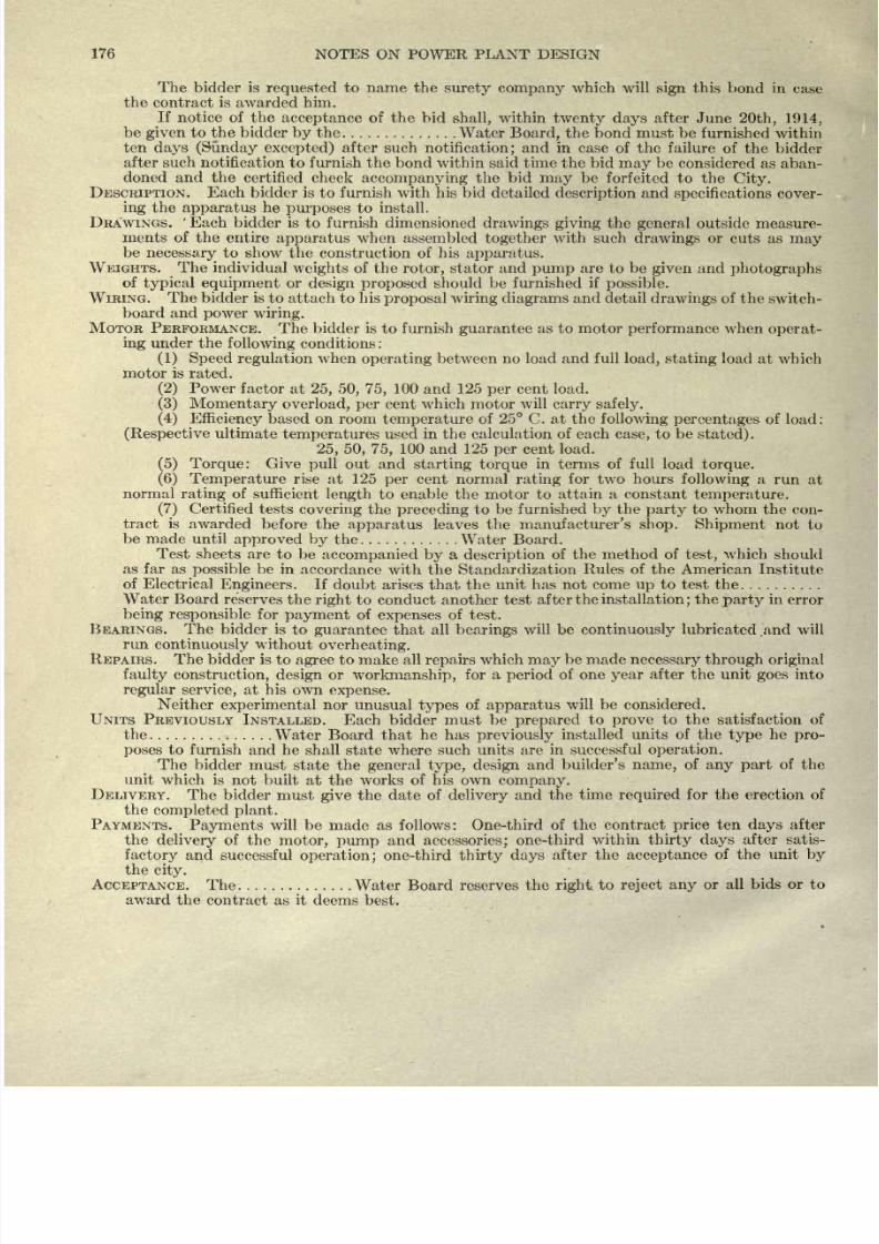
8/20/2019 notes on powerplant.pdf
http://slidepdf.com/reader/full/notes-on-powerplantpdf 182/202
176
NOTES
ON
POWER
PLANT
DESIGN
The
bidder is
requested
to
name
the
surety
company
which
will
sign
this bond
in
case
the
contract is
awarded
him.
If
notice
of
the
acceptance
of
the
bid
shall,
within
twenty days
after
June
20th, 1914,
be
given
to
the
bidder
by
the
Water
Board,
the
bond
must
be
furnished
within
ten
days
(Sunday excepted)
after
such
notification;
and in case
of the
failure
of
the
bidder
after such
notification to furnish the
bond within
said
time the bid
may
be
considered
as
aban-
doned and the
certified check
accompanying
the
bid
may
be
forfeited to
the
City.
DESCRIPTION.
Each
bidder
is
to
furnish
with
his
bid
detailed
description
and
specifications
cover-
ing
the
apparatus
he
purposes
to
install.
DRAWINGS.
'
Each
bidder
is
to
furnish
dimensioned
drawings giving
the
general
outside
measure-
ments of
the entire
apparatus
when
assembled
together
with such
drawings
or
cuts
as
may
be
necessary
to
show
the
construction
of his
apparatus.
WEIGHTS.
The
individual
weights
of the
rotor,
stator
and
pump
are
to
be
given
and
photographs
of
typical
equipment
or
design
proposed
should
be
furnished
if
possible.
WIRING.
The
bidder
is
to
attach
to
his
proposal wiring diagrams
and detail
drawings
of the
switch-
board
and
power
wiring.
MOTOR PERFORMANCE.
The
bidder
is
to
furnish
guarantee
as to
motor
performance
when
operat-
ing
under
the
following
conditions
:
(1) Speed
regulation
when
operating
between no load and
full
load,
stating
load
at
which
motor
is
rated.
(2)
Power
factor
at
25,
50, 75,
100
and
125
per
cent
load.
(3)
Momentary
overload,
per
cent
which
motor
will
carry
safely.
(4)
Efficiency
based on room
temperature
of
25 C.
at
the
following
percentages
of
load:
(Respective
ultimate
temperatures
used in the calculation of each
case,
to
be
stated)
.
25, 50,
75,
100
and
125
per
cent load.
(5)
Torque:
Give
pull
out and
starting
torque
in terms of full load
torque.
(6)
Temperature
rise
at 125
per
cent normal
rating
for two
hours
following
a
run
at
normal
rating
of
sufficient
length
to enable
the motor to
attain a
constant
temperature.
(7)
Certified tests
covering
the
preceding
to
be
furnished
by
the
party
to whom the
con-
tract
is
awarded
before
the
apparatus
leaves
the
manufacturer's
shop. Shipment
not
to
be
made
until
approved
by
the Water
Board.
Test
sheets
are
to
be
accompanied
by
a
description
of
the method
of
test,
which
should
as far
as
possible
be
in
accordance
with the
Standardization
Rules of
the
American
Institute
of Electrical
Engineers.
If
doubt
arises
that
the
unit has not come
up
to
test the
Water Board
reserves
the
right
to
conduct another
test
after
the
installation;
the
party
in
error
being
responsible
for
payment
of
expenses
of
test.
BEARINGS.
The
bidder
is to
guarantee
that
all
bearings
will
be
continuously
lubricated
.and
will
run
continuously
without
overheating.
REPAIRS.
The
bidder
is
to
agree
to make
all
repairs
which
may
be
made
necessary
through original
faulty
construction,
design
or
workmanship,
for
a
period
of
one
year
after
the
unit
goes
into
regular
service,
at
his
own
expense.
Neither
experimental
nor
unusual
types
of
apparatus
will be considered.
UNITS
PREVIOUSLY
INSTALLED.
Each bidder must
be
prepared
to
prove
to the
satisfaction
of
the
Water Board that
he
has
previously
installed
units
of
the
type
he
pro-
poses
to furnish
and
he
shall
state where
such
units are
in
successful
operation.
The
bidder must
state
the
general
type,
design
and
builder's
name,
of
any
part
of the
unit which
is
not
built
at
the
works
of
his own
company.
DELIVERY.
The
bidder
must
give
the
date of
delivery
and
the
time
required
for
the
erection
of
the
completed
plant.
PAYMENTS.
Payments
will
be
made
as
follows:
One-third
of the
contract
price
ten
days
after
the
delivery
of
the
motor,
pump
and
accessories;
one-third
within
thirty days
after
satis-
factory
and
successful
operation;
one-third
thirty
days
after
the
acceptance
of
the
unit
by
the
city.
ACCEPTANCE. The
Water Board
reserves the
right
to
reject
any
or
all
bids
or
to
award the
contract
as
it
deems
best.
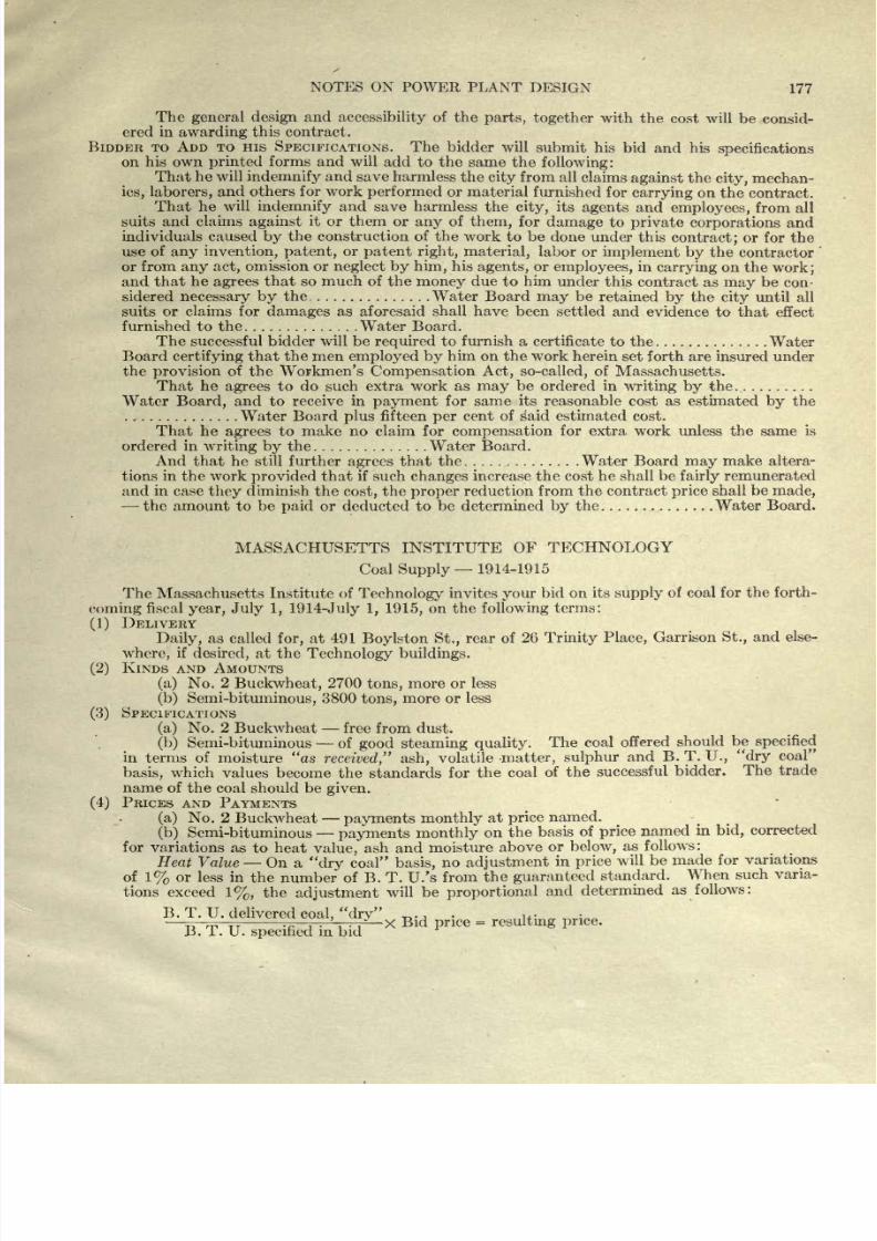
8/20/2019 notes on powerplant.pdf
http://slidepdf.com/reader/full/notes-on-powerplantpdf 183/202
NOTES ON
POWER
PLANT
DESIGN
177
The
general
design
and
accessibility
of
the
parts,
together
with
the
cost
will be
consid-
ered in
awarding
this
contract.
BIDDER
TO ADD
TO
HIS
SPECIFICATIONS.
The
bidder
will
submit his
bid
and his
specifications
on his own
printed
forms
and will
add
to
the
same
the
following:
That he will
indemnify
and
save
harmless
the
city
from
all
claims
against
the
city,
mechan-
ics,
laborers,
and
others
for
work
performed
or
material furnished
for
carrying
on
the
contract.
That
he
will
indemnify
and
save
harmless
the
city,
its
agents
and
employees,
from
all
suits
and
claims
against
it
or
them
or
any
of
them,
for
damage
to
private corporations
and
individuals
caused
by
the
construction of
the
work to be done
under
this
contract;
or for
the
use
of
any
invention,
patent,
or
patent right,
material,
labor
or
implement
by
the
contractor
or
from
any
act,
omission
or
neglect
by him,
his
agents,
or
employees,
in
carrying
on
the
work;
and that
he
agrees
that
so
much
of
the
money
due
to
him
under
this
contract as
may
be
con-
sidered
necessary
by
the
Water
Board
may
be
retained
by
the
city
until
all
suits
or claims for
damages
as
aforesaid
shall have
been
settled
and
evidence to
that effect
furnished to
the
Water Board.
The
successful
bidder will
be
required
to furnish
a
certificate to
the
Water
Board
certifying
that
the
men
employed by
him
on
the
work
herein set forth are
insured
under
the
provision
of
the
Workmen's
Compensation
Act,
so-called,
of
Massachusetts.
That
he agrees
to
do
such
extra
work
as
may
be
ordered
in
writing
by
the
Water
Board,
and to receive
in
payment
for
same
its reasonable
cost as estimated
by
the
.
,
Water
Board
plus
fifteen
per
cent
of
s'aid
estimated
cost.
That
he
agrees
to
make
no
claim for
compensation
for
extra work
unless
the
same is
ordered in
writing
by
the
Water Board.
And
that
he
still
further
agrees
that the
Water
Board
may
make altera-
tions
in
the work
provided
that
if
such
changes
increase
the cost
he
shall
be
fairly
remunerated
and in case
they
diminish
the
cost,
the
proper
reduction from the
contract
price
shall
be
made,
the
amount
to
be
paid
or
deducted
to
be
determined
by
the
Water
Board.
MASSACHUSETTS INSTITUTE
OF
TECHNOLOGY
Coal
Supply
1914-1915
The
Massachusetts
Institute
of
Technology
invites
your
bid on
its
supply
of
coal
for the forth-
coming
fiscal
year, July 1,
1914-July
1,
1915,
on the
following
terms:
(1)
DELIVERY
Daily,
as
called
for,
at
491
Boylston
St.,
rear of
26
Trinity
Place,
Garrison
St.,
and else-
where,
if
desired,
at the
Technology buildings.
(2)
KINDS AND AMOUNTS
(a)
No.
2
Buckwheat,
2700
tons,
more or
less
(b)
Semi-bituminous,
3800
tons,
more or
less
(3)
SPECIFICATIONS
(a)
No.
2
Buckwheat free
from
dust.
(b)
Semi-bituminous
of
good steaming
quality.
The
coal
offered
should
be
specified
in
terms
of
moisture
as
received,
ash,
volatile
-matter,
sulphur
and
B.
T.
U.,
dry
coal
basis,
which
values
become
the standards
for
the
coal
of
the
successful
bidder.
The
trade
name
of
the coal should be
given.
(4)
PRICES AND
PAYMENTS
(a)
No.
2
Buckwheat
payments
monthly
at
price
named.
(b)
Semi-bituminous
payments
monthly
on
the
basis
of
price
named
in
bid,
corrected
for
variations
as
to
heat
value,
ash
and
moisture
above
or
below,
as follows:
Heat
Value
On
a
dry
coal
basis,
no
adjustment
in
price
will
be
made
for
variations
of
1%
or
less in
the number of B. T.
U.'s
from
the
guaranteed
standard.
When
such
varia-
tions
exceed
1%,
the
adjustment
will
be
proportional
and
determined
as
follows:
B. T.
U.
delivered
coal,
dry
r>
^
TT
,
.
'
.
/
X
Bid
price
=
resulting
price.
B.
T.
U.
specified
in bid
8/20/2019 notes on powerplant.pdf
http://slidepdf.com/reader/full/notes-on-powerplantpdf 184/202
178
Ash
On
a
dry
coal
basis,
no
adjustment
in
price
will be made
for
variations
of
1%
or
less
above
or
below
the
per
cent
of
ash
guaranteed.
When
such variation
exceeds
1%,
the
adjustment
in
price
will
be
determined
as
follows:
The
difference
between
the
ash content
of
analysis
and
the
ash content
guaranteed
will
be
divided
by
2
and
the
quotient
multiplied
by
bid
price,
the
result
to
be
added
to
or subsracted
from
the
B.
T.
U.
adjusted
price
or
the bid
price,
if
there
is no
B. T.
U.
adjustment,
according
to
whether the
ash content
by analysis
is
below
or above the
per-
centage
guaranteed.
Moisture
The
price
will
be
further
adjusted
for
moisture content
in excess of amount
guaranteed,
the
deduction
being
determined
by
multiplying
the
price
bid
by
the
percentage
of
moisture
in
excess
of
the
amount
guaranteed.
(5)
SAMPLING
AND
TESTING
The
samples
of
coal shall
be taken
by
the
Institute
or
its
representative
and
no other
sample
will be
recognized.
The
coal
dealer
or
his
representative
may
witness
the
operation
of
the
sampling
if so
desired.
Samples
of
the coal
delivered
will be
taken
by
the
Institute or
its
representative
from
the
wagons
while
being
unloaded.
Two
or
more
shovelfuls
of coal
shall
be
taken
from
each
wagon
load
and
placed
in a
metal
receptacle
under
lock. Not
less
than
three times
in
any
one
month
the
samples,
thus
accumulated,
shall
be thoroughly
mixed
and
quartered
in
the
usual
manner.
The
final
sample
is
to
be
pulverized
and
passed through
an 80-mesh
sieve.
A
part
of
the
final
sample
shall
be
put
aside
in an
air-tight
jar
properly
marked,
for
the coal
dealer,
so
that
he
may
verify
results
if he so desires.
The
coal
shall
be
dried for
one hour
in
dry
air at
a
temperature
between
104
C.
and
105
C.
The
coal
shall
be
tested
by
the
Institute,
a
bomb
calorimeter
being
used.
Should the
coal
dealer
question
the
results,
a
sufficient
quantity
of
the
original sample
is
to
be furnished
him for
testing
if he
so
requests
it.
The
average
of
the results
of
the
tests
made
each
month
shall
be
the
basis
for
determining
the
price
to
be
paid
for
coal
delivered
during
that month.
(6)
LIMITS
Should the
heating
value
per pound
of
dry
coal
fall
below
14,500
B.
T.
U.,
or
should
the
moisture
exceed
3%,
or the
ash
exceed
7%,
or the
sulphur 1%,
or
the
volatile
matter
20%,
the
agreement
may
be
terminated
at
the
option
of
the
Institute.
(7)
THE RIGHT to
reject
any
or all bids
is
reserved
by
the
Institute.
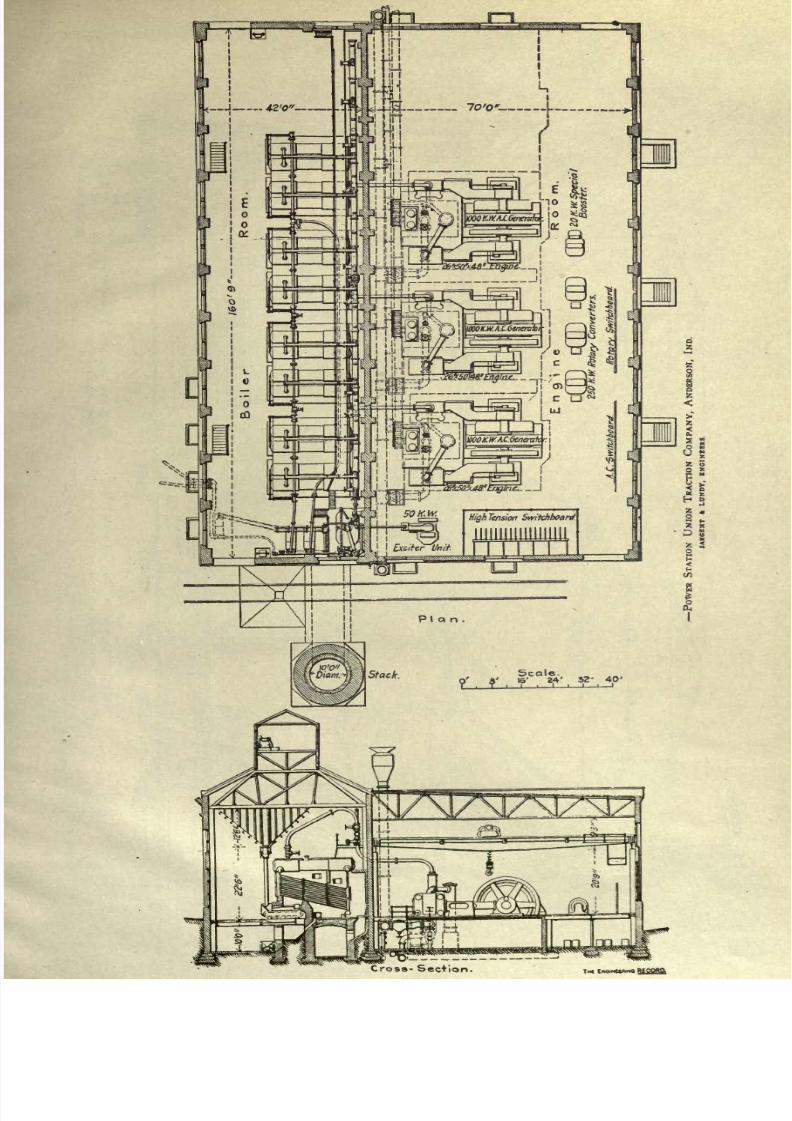
8/20/2019 notes on powerplant.pdf
http://slidepdf.com/reader/full/notes-on-powerplantpdf 185/202Cross-
Section.
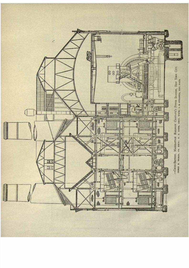
8/20/2019 notes on powerplant.pdf
http://slidepdf.com/reader/full/notes-on-powerplantpdf 186/202
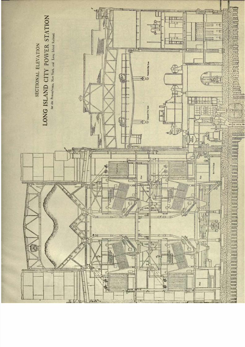
8/20/2019 notes on powerplant.pdf
http://slidepdf.com/reader/full/notes-on-powerplantpdf 187/202
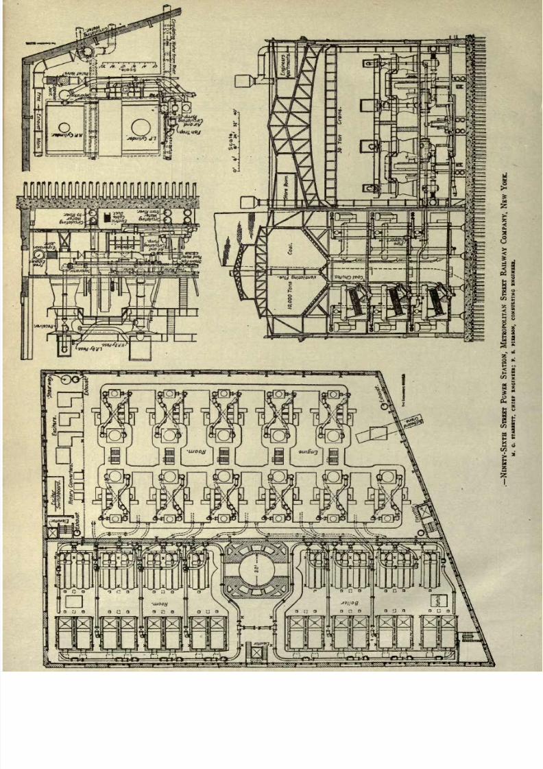
8/20/2019 notes on powerplant.pdf
http://slidepdf.com/reader/full/notes-on-powerplantpdf 188/202
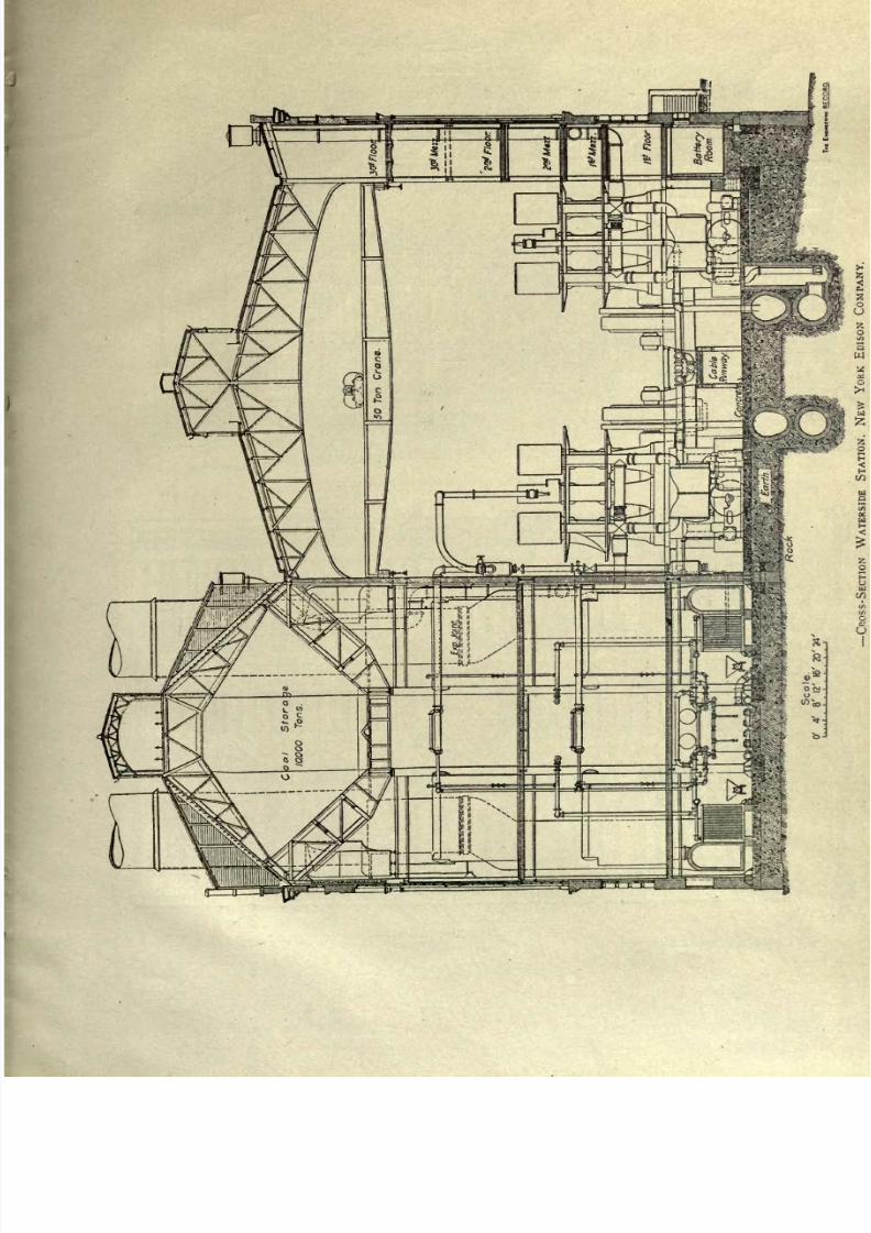
8/20/2019 notes on powerplant.pdf
http://slidepdf.com/reader/full/notes-on-powerplantpdf 189/202
-Jib
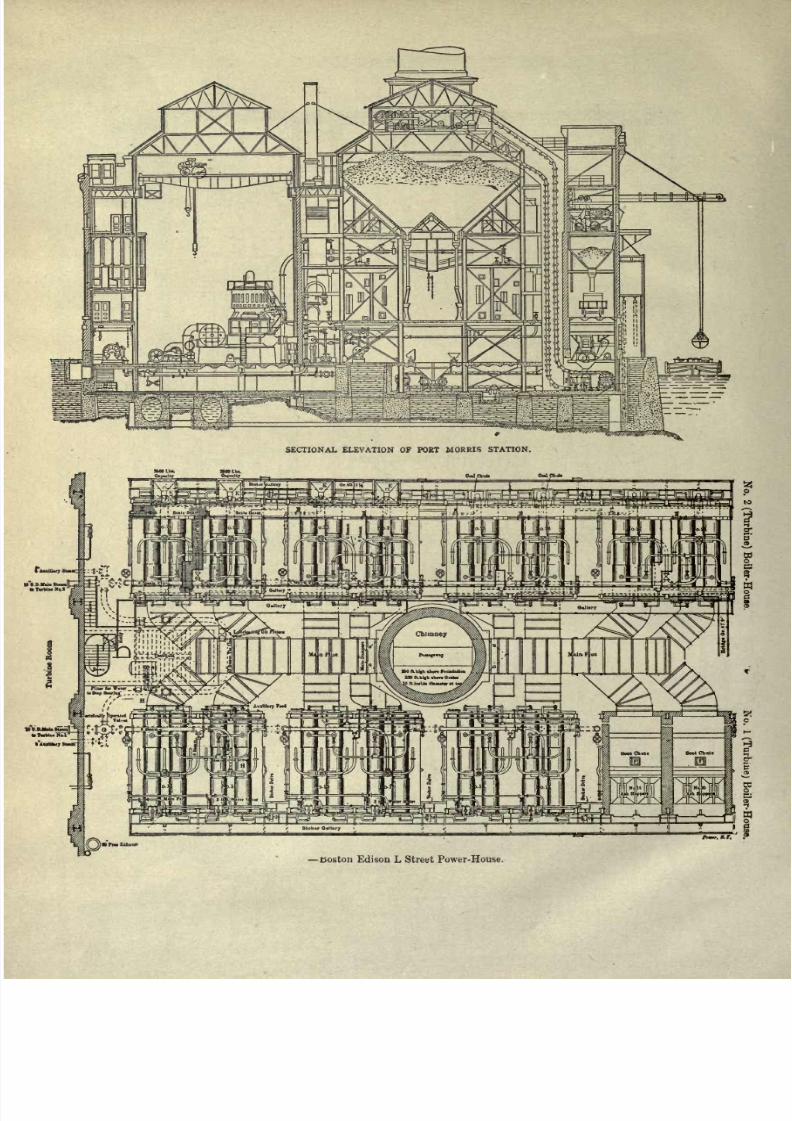
8/20/2019 notes on powerplant.pdf
http://slidepdf.com/reader/full/notes-on-powerplantpdf 190/202
SECTIONAL ELEVATION
OF
PORT
MORRIS
STATION.
Boston
Edison
L Street Power-House.
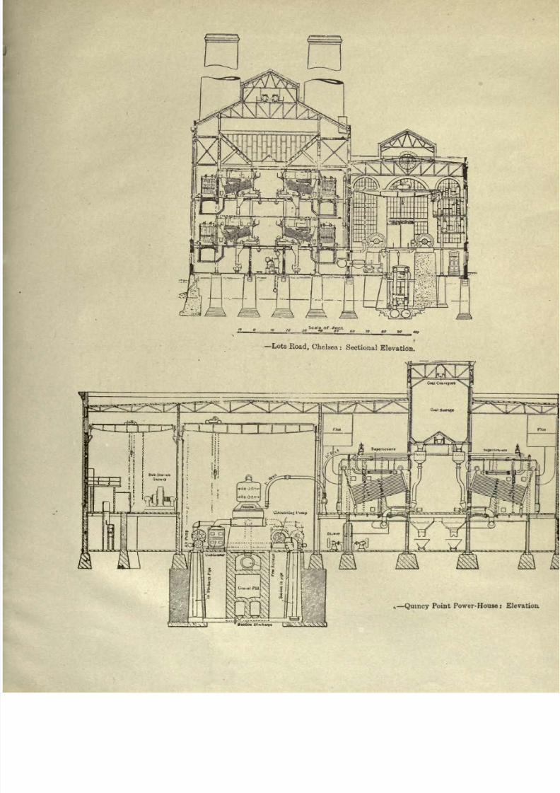
8/20/2019 notes on powerplant.pdf
http://slidepdf.com/reader/full/notes-on-powerplantpdf 191/202
.Lots
Road,
Chelsea:
Sectional
Elevation.
,
Quincy
Point
Power-
House:
Elevation
8/20/2019 notes on powerplant.pdf
http://slidepdf.com/reader/full/notes-on-powerplantpdf 192/202
8/20/2019 notes on powerplant.pdf
http://slidepdf.com/reader/full/notes-on-powerplantpdf 193/202

8/20/2019 notes on powerplant.pdf
http://slidepdf.com/reader/full/notes-on-powerplantpdf 194/202

8/20/2019 notes on powerplant.pdf
http://slidepdf.com/reader/full/notes-on-powerplantpdf 195/202

8/20/2019 notes on powerplant.pdf
http://slidepdf.com/reader/full/notes-on-powerplantpdf 196/202

8/20/2019 notes on powerplant.pdf
http://slidepdf.com/reader/full/notes-on-powerplantpdf 197/202
8/20/2019 notes on powerplant.pdf
http://slidepdf.com/reader/full/notes-on-powerplantpdf 198/202

8/20/2019 notes on powerplant.pdf
http://slidepdf.com/reader/full/notes-on-powerplantpdf 199/202
8/20/2019 notes on powerplant.pdf
http://slidepdf.com/reader/full/notes-on-powerplantpdf 200/202
UNIVERSITY
OF
CALIFORNIA
LIBRARY
BERKELEY
Return
to
desk
from
which
borrowed.
This
book
is DUE
on
the
last date
stamped
below.
19
1S48
LD
21-100m-9,'47(A5702sl6)476
8/20/2019 notes on powerplant.pdf
http://slidepdf.com/reader/full/notes-on-powerplantpdf 201/202
149
UNIVERSITY
OF
CALIFORNIA
LIBRARY

8/20/2019 notes on powerplant.pdf
http://slidepdf.com/reader/full/notes-on-powerplantpdf 202/202