Embed Size (px)
Citation preview
NFS-320
CONVERTIFIRE
converts legacy databases to ONYX databases.
Identifies issues
Converts AFP-300/400 to NFS2-640
Converts AFP-300 to NFS-320
Converts AFP-200 to NFS2-640/320
NFS-320/NFS2-640
2007
Small applications
Integrated power supply, keypad/display, 1 loop, 318 points, 4 NACS
Includes everything but batteries
320 CPU same as CPU2-640 except:
320 only 1 loop
Keypad in different location than 640, cannot mount in CAB-4 box
FIREVOICE 25/50
320 can interface to NFV-25/50Z5 voice evac system to control messages & speakers
Done thru software zone programming
EIA-485 connection
Single channel voice evac systems
ACS programming consists of making address 01 as GROUP M
For more than 8 speaker circuits, it can be expanded with NFV-25/50Z5, distributed audio panels
Provides 24 speaker circuits controlled by serial link
SINGLE CHANNEL
Sends only one message at any one time, multiple messages sent one at a time.
EVAC message sent to threat zone, then alert sent to outside zones
Multiple channel send out multiple messages to multiple speakers/circuits at same time
IPDACT-2 & IPDACT-2UD
October 14/2009 received UL with 320
NFS-320SYS
January 1/2010
Installed in CAB-4 cabinet
Allows retrofit of legacy panels B,C, or D size cabinets
Technical bulletins
TB10-03-01 NFS2-640 Firmware v.12.003.001 March 1/2012
Could affect NFS2-640 using v.12.000.004 thru 12.001.005
Activation of FCM-REL on one SLC loop may interrupt regular SLC communication on the other loop, provided there are NO MODULES on the 2nd loop.
If FCM-1-REL on loop 1 is activated, polling will be inhibited on loop 2 and NO trouble indicated, although a NO DEVICES INSTALLED trouble will come in.
OCCURS WHEN:
2-640 is 2 loops
2-640 firmware V12.000.004 thru 12.001.005
2-640 operating in FLASHSCAN
FCM-1-REL installed on one loop and the other loop does not have any modules.
Usually discovered during VI

Affects Oct/2008 to Feb/2010 products
DOES NOT affect NFS-320 or NFS2-3030
RECOMMENDED UPGRADE to v12.003.001
If all 4 conditions exist, upgrade ASAP
TB-09-12-01 NFS2-640 & NFS-320 FIRMWARE UPGRADE
DECEMBER 7/2009
March 31/2009 – availability of v.12.1.5 to fix AC FAIL conditions on NFS2-640 and NFS-320
REQUIRE upgrade of all NFS2-640 and NFS-320s to v.12.1.5
Failure to do so may result in reduced life expectancy of power supply
Ref. TB09-03-01
TB07-12-01 NFS-320 & NFS2-640 BATTERY TROUBLES
KAPS-24 v.1.0 power supply
Panels shipped before 11/30/07
May cause panel to enter false BATTERY TROUBLE or CHARGER FAULT even tho batteries are ok
Identified on label on U12EPROM
Marked as KAPSV1.00
Version 1.1 fixes issue
Anything after 12/03/07 is ok.
Check following PRIOR to upgrade:
Ensure batteries are 18AH to max 200Ah
Batteries less than 3 years old
If programmed by VERIFIRE TOOLS, make sure battery charger parameters are set

SOFTWARE USED TO RECONFIGURE LEGACY TO ONYX: SPECI-FIRE (??)
TB07-09-01 NFS2-640, NFS-320 RELEASING TYPE CODES W/VERIFIRE TOOLS 5.0
SEPTEMBER 17/2007
Affects modules with releasing type code labels using VFT 5.0
VFT 5.0 released 8/20/07
Affects SLC loop in either FLASHSCAN or CLIP mode
Will default Flashscan to NULL whe using point program serv menu
Affected modules will display as INVALID REPLY
When using Excel v5, will default to RELEASE, will display INVALID REPLY
Specific to nodules with releasing type code labels & programmed with v5.0
Also affects database upgrades w/v5.0 where modules have been edited or added.
Affects v5.0 from PC, laptop, NCS, or ONYXWORKS
Correct by manually programming valid flashscan type, either CONTROL or RELAY
NTSRUNTIMETPL.MDB

NFS2-3030
CONVERTIFIRE – converts 2020, AFP-1010 to NFS2-3030
AMPS-24/E
Primary power supply for 2-3030 (Sept/09)
Additional power available for main & auxillary outputs. Auxillary can be disabled.
Charges 7-200Ah batteries
Selectable charger current
5 point trouble reporting (added charger fault)
USB programmable
DOCUMENT 51907 for Install/Maint
Configured with PK-PPS sorftware
GAS DETECTION
NFS2-3030 interfaces to industry standard 4-20mA devices using FMM-4-20 module
FMM-4-20 connects to 2-3030 via SLC to collect, display, act on data received from gas or flame detectors, etc.
FMM-4-20
User programmed for up to 5 event thresholds, based on concentration level of gas being monitored
Executes appropriate pre-programmed response
Can be labelled as any:
Fire, security, non-fire trouble, pre-alarm, non-fire & critical process

NETWORK DISPLAY MODE
System Release 4 adds Network Display Mode
Allows 2-3030 to act as Network Annunciator for up to 4 DVC nodes and 1 other ONYX control panel
Eliminates expense of adding NCA2 to small networks
Mapping network node to 2-3030 on Network Mapping Menu will allow the 2-3030 to monitor & annunciate events for that node
Drill mapping for 2-3030 can only be changed thru VFT
In network mode, 2-3030 hasa ability to perform network ACK, RESET, SIG SIL, AUTO SILENCE and DRILL
Only on network nodes mapped to 2-3030 will be affected
Initiating AC, RESET, SIG SIL or DRILL on network node mapped to 2-3030 may affect nodes not participating in NETWORK DISPLAY MODE thru logic zone programming
Participating ONYX panel is mapped in the same manner as the NCA-2
3rd panel settings screen has been added to programming menu:
Network Display Mode: ON
Drill Mode: CUSTOM
TB10-07-02 FSB200/FSB-200S BEAM DETECTORS, USE OF ALARM VERIFICATION WITH BEAM DETECTORS AND NFS-3030/NFS2-3030 LCM FIRMWARE UPGRADE NOTICE
JULY 12/2010
FSB-200/200S
20 second alarm verification timer to help with false alarms
ISSUE: detectors programmed for alarm verification in 3030 & 2-3030 operating LCM firmware v.2.8.14 thru 3.3.2 WILL NOT initiate alarms
Detectors NOT programmed for alarm verification are NOT affected & will work.
DEFAULT is NO Alarm Verification
NFS2-640 & NFS-320 are NOT AFFECTED

Issue would be found during VI
Affected LCM-320 loop cards were manufactured May/05 to June/10
LCM firmware v.4.1.3 fixes issue
LCM-320 after 8/1/10 are ok
If more than 20 seconds required, LCM-320 needs upgrade to v.4.1.3
If 20 seconds not needed, DO NOT program it
TB09-09-01 LCM FIRMWARE V.3.2.4 RELEASED ADDRESSES OPEN CIRCUIT CONDITIONS ON XP10-M & FMM-1 MODULES
SEPTEMBER 28/09
XP10-M operating in flashscan or CLIP
If wired Class A, open circuit on initiating device ckt will initially cause open circuit trouble but will change to INVALID REPLY
Once in INVALID REPLY , module will continue to process active events on feed side of the circuit.
Active events on the return side will not be detected.
Specific to Class A with open .
Other Class A circuits on the same card are not affected.
Class B NOT affected.
FMM-1A in Class A or Class B on heavily loaded SLC loops operate in CLIP mode
Event activations from CLIP mode, FMM-1A with open circuit trouble may be delayed to reporting to panel. Delayed reporting depends on total # of detectors on loop.
80+ detectors will affect FMM-1 reporting times
v.3.2.4 corrects issue
NFS2-3030 requires upgrade of LCM and 2-3030 firmware

3030 requires just upgrade of LCM as 3030 firmware has not changed
LCM-320s shipped after 9/28/09 are v.3.2.4
TB-07-08-01 ACCLIMATE DETECTORS
AUGUST 20/07
Acclimate smokes (FAPT751/851) connected to 3030 or 2-3030 running v.2.7.1 thru v.2.11.4 LCM code and programmed for alarm verification may not properly report alarm
v.2.17.1 LCM code released 04/05
Anomoly may cause Acclimate smoke programmed for alarm verification to not report alarm if the following conditions are present
Acclimate detector is programmed for alarm verification
Alarm level reported doesn’t change for verification period
Smoke and/or heat levels remain the same for entire period
Smoke detector portion caused the initial verification & heat portion does not activate during confirmation period
No other device activated during entire verification period
If alarm level changes during confirmation period an alarm will be reported
Detectors NOT programmed for alarm verification will not be affected
LCM v.2.16.3 corrects issue
Label on LCM EEPROM in lower left corner of board marked U22
All systems using v.2.7.1 thru 2.11.4, LCM code should be upgraded

TB07-04-01 STANDOFF INSTALLATION
Standoffs for LEM-320 behind LCM-320 can be installed in wrong location
Standoffs mounted in middle 4 holes

ENCLOSURES
CAB-4, AUDIO DRESS DOORS, EQ EQUIP, BATTERY BOXES
CAB-4 SERIES
ONYX CABINETS (BACKBOX/DOOR)
BACKBOXES FEATURE:
One to four rows for mounting CPU, CHASSIS, AMPS, ETC
Bottom row used for power supply & batteries
CAB-4 – NFS-320SYS, NFS2-640, NFS2-3030
NFS-320 has its own cabinet
SBB – A4 SBB ->SURFACE BACK BOX
A -> # OF EQUIPMENT ROWS (A=1, B=2....)
4 -> CAB 4 SERIES
DOORS
DR-A4-B R DR -> DOOR
A -> # OF EQUIPMENT ROWS (A=1, B=2....)
4 -> CAB 4
B -> STYLE B blank door, nothing means Windows
R -> RED, nothing means Black

AUDIO DRESS DOORS
ADDR-B4 B R ADDR ->AUDIO DRESS DOOR
A -> # OF EQUIPMENT ROWS (A=1, B=2....)
4 -> CAB 4
B -> STYLE B blank door
R -> RED, nothing means Black
EQ CABINETS
Equipment blank mesh doors
Same dimensions as CAB-4
Eliminates space for rows
Back box and door available in B,C,D sizes w/ optional trim ring
CAB-4 hinges mounting – ATTACH BEFORE EQUIPMENT INSTALLED IN CABINET
Lock must installed in lock position when key removed

INTELLIGENT DETECTORS
B224RB RELAY BASE – ONE FORM C relay for control of auxillary functions ie. Door release, etc.
2 modes – SHORT delay – JP1 (1&2) 60-100ms
LONG delay – JP1 (2&3) 6-10 seconds
N/O or N/C
FAPT-851 ACCLIMATE PHOTO/THERMAL detector
Multi-criteria smoke using photo & thermal to increase immunity to false alarms
Internal microprocessor adjusts sensitivity based on environment without programming
Photo sensitivity to smoke increases when rise in heat is sensed.
Capable of heat only mode, enabled by special command from panel.
FSB-200 (S)
Addressable beam detector
Transmitter, receiver, reflector protection range is 16 to 318 feet
Built in isolators
Style 7 operation
FSB-200S
Integrated sensitivity test feature in the way of filter attached to servometer inside optics
Activation of remote test station rotates filter into pathway of light beam (RTS451)
Quick & easy test without accessing device
Servometer needs 24VDC external source

Installation includes completion of coarse and fine alignment procedures, (I56-2544-004R):
Coarse alignment
Fine alignment
Final gain adjustment
Final verification
Specs, wiring, pre-alignment, coarse adjust, fine adjust, final gain, final vi, short circuit isolation, sensitivity selection, reflector test card procedure
D SERIES DUCT SMOKES
DNR – samples air current passing thru duct
Fan shutdown, etc
Low flow technology detects at air speed velocities of 100 to 4000 FPM
Pivoting housing
Remote alarm LED (RA400Z)
Remote test RTS451/RTS451KEY
DNRW- NEMA 4 rating
Watertight enclosure
Not substitute for open area smokes
Not substitute for early warning
Not replacement for regular fire detection system
Tamper signal when cover removed
Standard smoke head (separate)
Cover isolates head from low flow feature for simple maintenance
2 wire loop for connection to smoke and optional relay or control module
Remote test device requires additional 2 wire for power
D SERIES
D2- 2 wire conventional
D4120 – 4 wire conventional
D4120W – 4 wire conventional watertight
DNR – Intelligent, non relay
DNRW Intelligent non-relay, watertight
FSC-851 – INTELLIQUAD MULTI-CRITERIA
4 sensing technologies that work together
Photo, thermal, carbon monoxide, infrared
DOES NOT generate 4 separate signals

ADDRESSABLE MONITOR MODULES
Interface to conventional circuits
Retrofits
Interface to N/O contact alarm devices
Two wire smokes
Non-alarm devices
Manual pull stations
New style H TYPE, same model #, new features
Terminal labelling on the side, Side mounted terminals for easy installation, Re-oriented address switches
Some modules require 24VDC (T11/T10)
Conventional circuits (T8/T9)
Loop connections (T1/T2)
FMM-1 MONITOR MODULE
Used to monitor a zone
Wired as Class B (Style B) or Class A (Style D)
47kohm EOL
No resistor required for Style D
Max IDC loop length is 2500 ft
N/O, dry contact, alarm
4 wire smokes, pulls, flows, SV, heats, non-alarm contact types
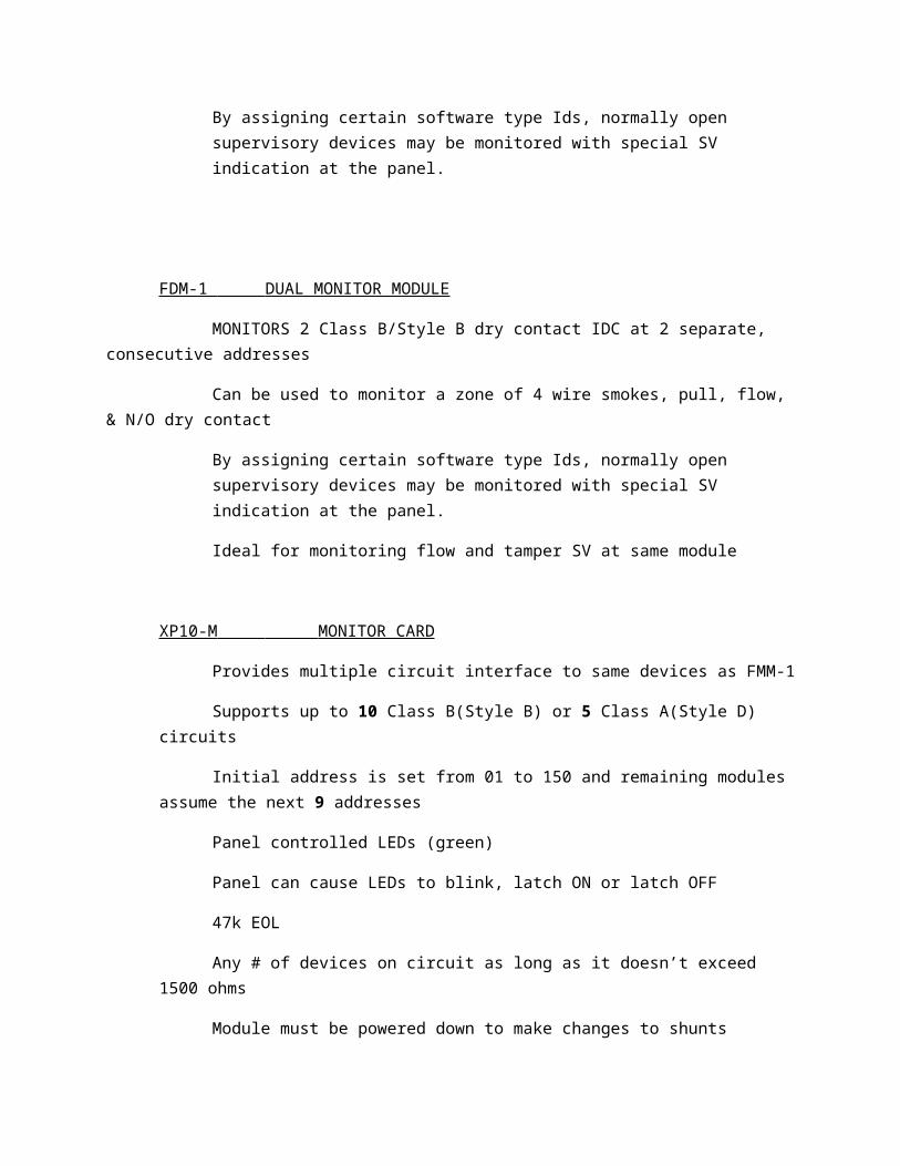
By assigning certain software type Ids, normally open supervisory devices may be monitored with special SV indication at the panel.

FDM-1 DUAL MONITOR MODULE
MONITORS 2 Class B/Style B dry contact IDC at 2 separate, consecutive addresses
Can be used to monitor a zone of 4 wire smokes, pull, flow, & N/O dry contact
By assigning certain software type Ids, normally open supervisory devices may be monitored with special SV indication at the panel.
Ideal for monitoring flow and tamper SV at same module
XP10-M MONITOR CARD
Provides multiple circuit interface to same devices as FMM-1
Supports up to 10 Class B(Style B) or 5 Class A(Style D) circuits
Initial address is set from 01 to 150 and remaining modules assume the next 9 addresses
Panel controlled LEDs (green)
Panel can cause LEDs to blink, latch ON or latch OFF
47k EOL
Any # of devices on circuit as long as it doesn’t exceed 1500 ohms
Module must be powered down to make changes to shunts
DO NOT set base above 150
NEVER mix alarm and tamper devices on same circuit.
To Configure:
For Class A(Style D), remove A/B SLCT shunt
When Class A(Style D), alternate circuits are paired together & addresses are 2,4,6 or 8.
With A/B SLCT shunt in place, module is configured for 10 Class B(Style B) circuits 0-9
It is possible to disable ONE or TWO circuits in Class B or ONE circuit in CLASS A by installing a shunt in DISABLE 1 or DISABLE 2 positions of J1

Modules disabled from highest downward
Can be configured to send signal to NFS-320 or NFS2-640 to activate on board NAC circuits & alarm relay in event of failure of panel’s CPU – Jump CL of J1 enables feature
Degraded Mode
If system enter degraded mode due to failure of CPU:
NFS-320/2-640: General Alarm
Initiation of any inputs puts panel in full GA
NFS2-3030: per each SLC loop, alarm on any input on that loop puts panel in full GA.
FZM-1 FLASHSCAN ZONE MODULE
Used to monitor & supervise a zone of 2 wire, 24VDC smokes on Class A or Class B
Requires separate 24VDC power to power 2 wire detectors
Supervises connection of the power
XP6-MA SIX ZONE MONITOR MODULE
Interface between ONYX and conventional 2 wire smoke detection zones
Common SLC input used for all modules and share common external supervisory supply and ground. Otherwise, they operate individually
Transmits status of zone and supervises zone of detectors and connection of external power supply
Initial address is set from 01 to 154 and remaining modules assume the next 9 addresses
Panel controlled LEDs (green)
Panel can cause LEDs to blink, latch ON or latch OFF
It is possible to disable ONE or TWO circuits in Class B or ONE circuit in CLASS A by installing a shunt in DISABLE 1 or DISABLE 2 positions of J1
Modules disabled from highest downward
Must be powered down to change shunts
DO NOT set base above 154
SHOWN CONFIGURED FOR 3 CLASS A(STYLE D) CKTS WITH ONE CIRCUIT DISABLED
To configure for 3 Class circuits, REMOVE BOTH A/B SELECT shunts
Alternate circuits paired together
Other addresses available for other devices
With A/B SHUNT in place, configured for 6 Class B circuits
Consecutive range of addresses to base address +5
3.9k EOL
2 wire detectors must be listed w/XP6-MA
FMM-4-20 ANALOG INPUT MODULE
Translates 4-20mA signal from 2 or 3 wire sensors and communicates in flashscan
Provides unique non-alarm signal under UL NM listing
Requires 24VDC power supplied to power circuit
Supervises power
Transmits status of sensor (normal, open, alarm) to panel
4mA = 0% signal, 20mA = 100% signal

4mA as 0% allows panel to distinguish between zero signal and open circuits
Allows low powered devices to be directly powered by loop
Developed in 1950s
Only one sensor can be connected to the module
28 – 30 – 32 – 34 – 36
64 – 66 – 68 – 70 - 72
User programmed for up to 5 event thresholds, based on concentration level of gas being monitored
Executes appropriate pre-programmed response
Can be labelled as any: Fire, security, non-fire trouble, pre-alarm, non-fire & critical process

ADDRESSABLE CONTROL MODULES
Redesigned like monitor modules H TYPE
FCM-1 CONTROL MODULE
Notification appliances
Monitor telephone circuits
Activated manually or thru programming
Supports 2A of resistive load
1A of inductive load (mechanical bells or horns)
Can be wired Class A or Class B NACs
Size NAC using voltage drop calc software
47k EOL
Power supervision relay required at end of 24VDC power run
Except if last device on power run is a flashscan module using Type ID that provides built in power supervision
Supports speaker circuits Class A or Class B
Class B – 47k EOL
Class A – 100uf non polarized capacitors are required across terminals 6&9, 7&8
Audio circuit wiring must be twisted pair as minimum
Speakers must be listed for fire protection
Can be used to replace the U Type FCM-1 module in existing fire phone applications
When used for fire phones,
Remove jumper J1, located on back cover of module
MODULE BARRIER
Used in non power limited applications

CB500 module barrier used to separate power limited and non power limited terminals
Must be used in 4x4 box
Power limited wiring placed in isolated side of barrier
XP6-C MULTI CIRCUIT NAC MODULE
Provides 6 supervised Class B/Style Y, or 3 Class A/Style Z circuits for control of NACs
Also used for fire phones
External power must be supplied on command from panel
XP6-C disconnects supervision& connects external power supply across the load devices
Initial address is set 01 to 154, remaining assume next 5 addresses
With A/B SHUNT in place, configured for 6 Class B circuits
With A/B SHUNT removed, configured for 3 Class A circuits
Alternate circuits paired together
Addressed 0,2,4....
Ie. Module set to 28, Style Z – 28,30,32, 29,31,33 available for other devices
It is possible to disable ONE or TWO circuits in Class B or ONE circuit in CLASS A by installing a shunt in DISABLE 1 or DISABLE 2 positions of J1. Extra addresses freed up for other devices
Modules disabled from highest downward
Must be powered down to change shunts
# of modules disabled is affected by A/B Shunt
If configured for Style Z and shunt is installed across DISABLE 1, 3 addresses available under Class A, module would use 2 addresses
Short circuit protection can be enabled to protect external power supplies from shorts on NACs.

Enable short circuit protection when a single power supply is shared by multiple NACs. Short circuit protection can be disabled only when a power supply is not shared by multiple NACs.
There is an active short circuit protection option for each address. The board is shipped with this option disabled for each address represented by six large shunts on the “Disable Short Circuit Protection” area. To enable short circuit protection for an address, remove the correspondingshunts on the “Disable Short Protection” area. When enabled, this option will isolate a short occurring on any active circuit allowing the remaining circuits to continue normal operation.
NOTE: Power supply monitoring should not be used for audioapplications. The short circuit protection feature is alsonot available for audio applications.
NOTE: The XP6-C does not provide ring back when used as a firefighter telephone circuit.
NOTE: Short circuit protection may only be enabled if power supply monitoring is enabled.
NOTE: This feature is not for use with all Fire Alarm ControlPanels. Please consult with Technical Services beforeenabling this feature.
NOTE: Place unused shunts on single pin to store on board forfuture use.
NOTE: Power must not be applied to the unit when changing functionality ofthe shunts.
NOTE: Whether in Class B or Class A wiring, power supply monitoring andshort circuit protection must be enabled on the NAC circuits that are sharinga power supply.
NOTE: Short circuit protection can only be disabled if a power supply is notbeing shared by multiple NACs.
SYNCHRONIZATION
SYNC-1 SYNC CARD Works with System Sensor SpectrAlert & SpectrAlertAdvance series to provide means of sync’n temporal coded horns and timing of strobe flashing
Enables silencing of horns in horn/strobe combos over 2 wire circuit while leaving strobes active
Capable of syncing 6 Class B or 3 Class A circuits

Multi circuit NAC moduleEach set of 6 Class B are wired to term block with 47k EOL
Each of 3 Class A share 2 terminal blocks
XP6-C has provision for connection of external power source if source desired
All NACs can be wired powered by separate external supplies or a single supply can be shared among multiple NACs
FRM-1 RELAY MODULE Dry contact outputs for activating auxiliary devices
Form C
2 sets of contact switch together (DPDT) are rated for 2A resistive or 1A inductive or 0.5A Pilot duty(?)
Activated manually or thru panel
DOES NOT supervise controlled circuits
XP6-R RELAY CARD 6 separately addressed Form C relays
Single isolated set of dry contacts provided for each module. N/O or N/C
Addressed 01 to 154
With A/B SHUNT in place, configured for 6 Class B circuits
With A/B SHUNT removed, configured for 3 Class A circuits
Alternate circuits paired together
Addressed 0,2,4....
Ie. Module set to 28, Style Z – 28,30,32, 29,31,33 available for other devices
It is possible to disable ONE or TWO circuits in Class B or ONE circuit in CLASS A by installing a shunt in DISABLE 1 or DISABLE 2 positions of J1. Extra addresses freed up for other devices
Modules disabled from highest downward
Must be powered down to change shunts

# of modules disabled is affected by A/B Shunt
FCM-1-REL RELEASING MODULE Provides additional safeguards & features specifically designed for suppression releasing
Power for release solenoids runs thru module for full time supervision ensuring minimum voltage to activate
In Style D (Class A) configuration, device will monitor solenoid, even in event of short circuit
NO EOL required
ONE 24VDC or 2 12VDC solenoids per circuit
REQUIRED for all NEW flashscan mode releasing applications withNFS2-3030(V14+)NFS2-640 (V12+)NFS-320 (V12+)
Use FCM-1 for rfeleasing applications on NFS-640, 3030, and ALL CLIP mode panels
When using FCM-1-REL in Class A, remove J1 (inside module)
REDUNDANT PROTOCOLMinimizes likelihood of unintentional release.
MUST be armed first with pair of signalsEnters 3 second window awaiting pair of signals
If no confirmation, module will auto-reset
MODULE MOUNTING
4X4 box
Supplied with plastic cover
Notifier offers SMB500 surface mount box
CB500 Module barrier

MODULE CARD MOUNTING
BB-XP CabinetOne or 2 modulesInternal chassis with offset mounting
CHS-6 chassis supports mounting of up to 6 multi circuit cards
BB-25 back boxHolds one CHS-6
CAB-4 enclosureHolds up to 4 CHS-6
Module cards can be mounted in separate enclosure when used with NFS-320, or inside cabinet on 2-640/2-3030

SMOKE CONTROL MODULES
SCS-8 – smoke control station
SCE-8 – smoke control expander
Provides ONYX with capability to control & display status of AHU fans and dampers
MAX configuration of 32 pairs, system capability to control & display status of up to 512 separate fans/dampers
ADDRESS 1 ADDRESS 2 ADDRESS 3
SCS-82 modes of operation:
Fire fighters smoke control station (FSCS)HVAC
FSCS (2-3030 & NCA-2 ONLY)Helps maintain and enable environment in evacuation routes during time required to evacuate people from areas
Helps restrict movement of smoke from fire area
Helps provide conditions in non-smoke areas that will help fire officials conduct search and rescue
SCS intended to have highest priority over associated fan & damper functions.
REQUIRES CONTROL AND VERIFICATION OF A PARTICULAR DEVICE
NFS-2-640 can only be used if connected to NCA-2 network annunciator
Capability doesn’t exist when NCA-2is being used as primary display for NFS2-640 (Not functioning as network display)
HVAC ModeCapable of monitoring and controlling both HVAC, either separately or by overriding normal building usage

When used for smoke control, HVAC can:Supply outside air to a spaceReturn air to a spaceExhaust air from a space to outside
HVAC DOES NOT require control and verification of a particular device
HVAC mode is not consistent with UL & NFPA standards for smoke control. This mode should be used for fan shutdown and building HVAC and A/C purposes only.
SWITCH GROUPSSCS/SCE-8 has 8 switch groups, each with 2 LEDs and 1 switch
Each annunciator has ACK switch which is also Lamp Test
Green LED means all working in automatic mode
If any switches moved, AMBER ‘Manual’ LED lights
Each fan/damper has one switch group on SCS/SCE
Each group has up to 4 points that could be used to control a fan/damperFAN ON (Damper Open)
FAN OFF (Damper Closed)
MONITOR/VERIFY FAN ON/DAMPER OPEN
MONITOR/VERIFY FAN OFF/DAMPER CLOSEDIf fan/damper requires ALL 4, then 2 control modules must be connected to the device & ONE point would be for each of the 4 functions
AUTO – alarm on panel, module will function per programming
OPEN/ON – overrides auto programming procedure, leaving it in OPEN/ON position

CLOSED/OFF - overrides auto programming procedure, leaving it in CLOSED/OFF position
Modules can be mounted inside CAB-4 using ADP-4 annunciator dress plate. Each plate can hold up to 4 modules & uses 1 row in the cabinet
Can also be mounted in ABS-4D annunciator surface box
ALL SCS/SCE modules configured for FSCS mode MUST be installed in same room as FACP of NCA to which they are connected.
INSTALLATIONSubject to same requirements as ACS annunciators
Filtered, regulated 24VDC power supplied to each module
Connection between SCS & SCE with ribbon cable
SCS DOCUMENTATION (DOC#15712)
CONON/OP – CONtrol module used to turn ON a fan or OPEN a damper
CONOFF/CL – CONtrol module used to turn OFF a fan or CLOSE a damper
VERON/OP – VERify ON fan or OPEN damper
VEROFF/CL – VERify OFF fan or CLOSED damper
VERIFICATIONMonitor ON/OFF state of a fan or OPEN/CLOSED state of damper
Contacts connected to sail switch determine if module is to monitor ON/OPEN or OFF/CLOSED
Verify ON state (N/O contact) T7/T8
Verify OFF state (N/C contact) T7/T8
Normally, addressable control modules are used to activate & deactivate NACs
When used with smoke control, they control ON/OFF, OPEN/CLOSED

CONTROL/VERIFICATIONIe. FCM-1 wired to break power to fan upon activation (CONTROL OFF)
Once fan is turned off, FMM-1 is activated by change in state of fan’s switch (CONTACT CLOSE)VERIFY OFF
TYPE COMBINATIONS
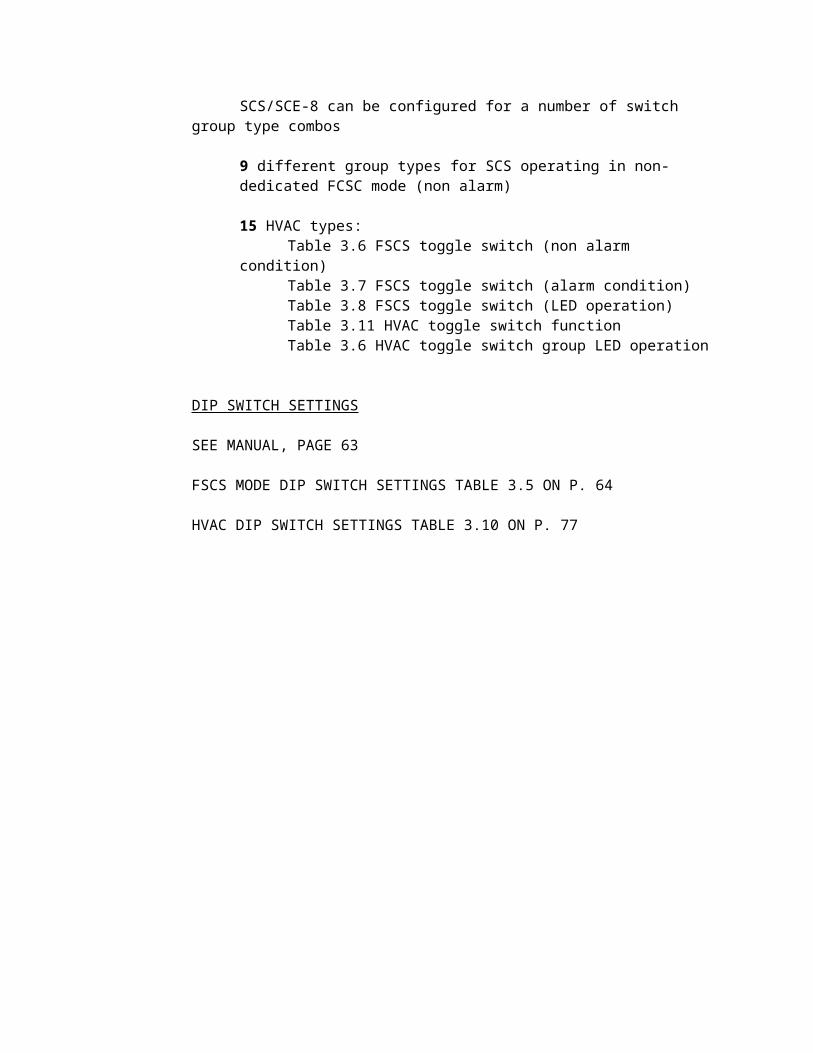
SCS/SCE-8 can be configured for a number of switch group type combos
9 different group types for SCS operating in non-dedicated FCSC mode (non alarm)
15 HVAC types:Table 3.6 FSCS toggle switch (non alarm condition)Table 3.7 FSCS toggle switch (alarm condition)Table 3.8 FSCS toggle switch (LED operation)Table 3.11 HVAC toggle switch functionTable 3.6 HVAC toggle switch group LED operation
DIP SWITCH SETTINGS
SEE MANUAL, PAGE 63
FSCS MODE DIP SWITCH SETTINGS TABLE 3.5 ON P. 64
HVAC DIP SWITCH SETTINGS TABLE 3.10 ON P. 77

PROGRAMMINGSCS special EIA-485 control annunciators
Points must be mapped to control module & monitor module assigned to each switch group
First, define required addresses as FSCS or HVAC
SLC can support up to 32 addresses for ACS, SCS, LDM annunciators & UDACT digital communicators
Each address supports up to 64 points on NFS-320 or NFS2-640
Each address supports up to 96 points on NFS2-3030 or NCA-2 BUT each point MUST be programmed, whether used or not.
POINT: Point 1 or 64 (or 96)
MODE: Control for a control module
SOURCE: SLC loop address of control module
RELAY MODULE: Control
CONTROL MODULE: Control
MONITOR MODULE: Verify
SCS-8L/SCE-8L SMOKE CONTROL LAMP DRIVER/EXPANDER Designed to interface with custom graphic annunciator
Each SCS-8L has capability to CONTROL and MONITOR 8 AHU fans or dampers
Can operate in FSCS or HVAC
Max config of 32 pairs
Can control and display status of up to 512 separate AHU fans or dampers
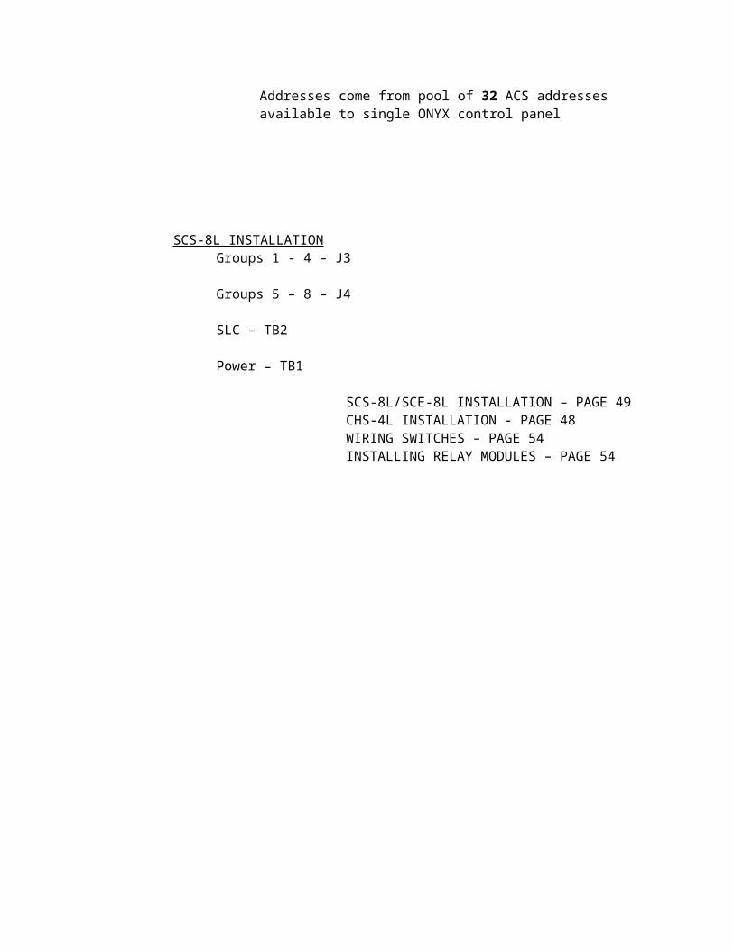
Addresses come from pool of 32 ACS addresses available to single ONYX control panel

SCS-8L INSTALLATIONGroups 1 - 4 – J3
Groups 5 – 8 – J4
SLC – TB2
Power – TB1
SCS-8L/SCE-8L INSTALLATION – PAGE 49CHS-4L INSTALLATION - PAGE 48WIRING SWITCHES – PAGE 54INSTALLING RELAY MODULES – PAGE 54

PROGRAMMMING BASICS
TYPE CODES
Software selections for SLC loop devices
Apply to 3 basic categories of SLC devices:
Detector, monitor, control
TYPE IDs
Do not actually change manner in which device operates
Codes define how control panel is to respond to activation of input device or control functioning of an output device
5 basic threat categories
Alarm, supervisory, security, trouble, other event (2-3030 only)
Codes further define whether a device change in status should be latch or tracked by a point.
MONITOR: LATCHING fire alarm signal
NON-FIRE: MONITOR non-fire alarm devices
PULL STATION: LATCHING without alarm verification
WATERFLOW: LATCHING waterflow
SPRINKLER SYS: NON-LATCHING without verification
DRILLS WITCH: EVAC from remote location
ABORT SWITCH: NON-ALARM abort function
NFS-320/NFS2-640 contain 4 onboard convention NACs which can be programmed with certain codes:
CONTROL
STROBE CKT
HORN CKT

SPEAKER
RELEASE CKT
ALARMS PENDING
NFS2-3030 programming manual contains TYPE CODES Appendix – PAGE 138
BOOLEAN LOGIC
Logic gates. AND, OR, NOT......
Used alone or in combinations
Series or parallel is used to control precedence of operations
OR
Logical disjunction
Results in a TRUE state for output whenever ONE of the inputs is TRUE
AND
Both inputs TRUE
NOT
Output is inverted of input
VENN DIAGRAM
Graphically represents the results of combining basic Boolean operators
XOR
Onyx system’s XOR is called ONLY1
Can be used to GATE activation of a releasing mechanism with an abort switch
If pulled within certain period of time following activation of a detector, switch aborts the pending activation of the releasing device. EXAMPLE ONLY, LOGIC NOT NEEDED IN ONYX.

SOFTWARE EQUATIONS
Written to define relationships between inputs and output devices
Equations help convert human language into format understood by panel
If this detector or this pull is activated, turn on these strobes
LOW (0) – NORMAL, NOT ACTIVATED
HIGH (1) – ALARM, ACTIVATED
OR(L1D01,L1M03)
CBE CONTROL BY EVENT
Method of controlling outputs by activation of specific inputs
Finite limit to # of elements that can be in CBE equation
Software zone can be used to accomplish same programming objective with less effort
LOGIC ZONES
General zones used as an arguement in logic equations, implemented using logic zones
ONYX systems also offer Trouble zones (2-3030), Releasing zones & Special zones
Logic zones defined by logic equations which is CBE equation that employs a logic function
Whenever logic equation becomes TRUE, all outputs mapped to that logic zone will activate.
Logic zone can then be programmed into zone map for each device intended to control
NFS-320 & NHS2-640 have capability of 20 logic zones, ZL1-ZL20
NFS2-3030 has capability of 1000 logic zones, ZL1-ZL1000
KDM-R2 – 80 character display shows E0 to E9 for logic zones 1-10 & L0 to L9 for 11-20
Once logic zone has been added to zone map for an output device, we have CBE solution
TROUBLE ZONES
Defined by equation with logic
When trouble equation becomes true, all outputs mapped will activate
Trouble zone is programmed into zone map for each output device intended to control
NFS-320/NFS2-640 DO NOT HAVE TROUBLE ZONES
NFS2-3030 HAS 100 TROUBLE ZONES, ZT1-ZT100
NFS2-3030 programming manual has system troubles appendix on PAGE 144
RELEASING ZONES
USED TO CONTROL RELEASING OPERATIONS
NFS-320/NFS2-640 have 10 releasing zones, R0-R9
NFS2-3030 has 10 10 releasing zones, R0-R9
DELAY TIME – 60 seconds
SOAK TIME - defines length of time to dump releasing agent on activation.
0= active until reset
DO NOT USE SOFTWARE DISABLES FUNCTIONS AS LOCKOUT
NFS-320/NFS2-640 – DO NOT ENABLE BACKUP OPTION SWITCH FOR ANY OF THE NACs IF USED FOR RELEASING

NFS-320/NFS2-640 – Limit of 73 characters including (,) & commas
NFS2-3030 – 80 characters
Limit of 20 arguements with 10 functions (or one time delay)
LOGICAL CONJUNCTION
2 place logical operation that results in a value of TRUE if both of its operands are true, otherwise value is false
EXCLUSIVE CONJUNCTION
Type of logical disjunction on two operands that results in a value of TRUE if AND only if exactly one of the operands is true
XOR = when more than 2 inputs are used, a HIGH OUTPUT results when there are and ODD # of TRUES (See ONLY1, only one input has t be true

IP COMMUNICATOR
Use existing IP networks (LAN, WAN) & internet connections to transmit alarms
Eliminates cost of phone lines
Increased supervision from once a day to every 30-90 seconds
No change to existing panel configuration, connects directly to panel’s dialer outputs
Works over any type of Ethernet 10/100 base T
DHCP or static IP
Less than 10 second alarm transmission line
Auto register can be pre-configured offsite
Can connect to primary and secondary output of panel’s DACT
Optionally, Secondary DACT can be connected to phone line if required
Communicates contact ID info to compatible TELDAT receiver via internet
UL-864 9th edition listed for signalling type “OT” other transmission technologies
PSDN(?) for both proprietary & commercial central stations
Listing meets all requirements for a single communications line under NFPA72
ANY FAILURE annunciated at supervising station WITHIN 5 MINUTES
If communication failure with supervising station, indicates at panel
If portion of communication path can’t be monitored, redundant communication path shall be provided
Failure of both primary and redundant communication paths shall be shown at supervising station within 24 HOURS. USUALLY DONE WITHIN 90 SECONDS
System units at supervising station shall be restored to service within 30 minutes if failure
IP Communicator simulates standard PSTN analog line
During event, it senses off hook status, counts digits of the dialed phone number, then begins collecting CONTACT ID data

FRAMES the CONTACT ID data using UDP packets (UDP instead of TCP/IP when very small amounts of data need to be sent) with 512bit AES
Receiver decrypts & unpackets data and sends ASCII data to software
Automation software or receiver can provide the “kiss-off” signal to panel
Communicator ships with:
30” telephone cable
2 ferrite rings
2 1k ohm resistors
Manuals/cd
Quick programming guide
P1 – RESET JUMPER – when jumped, will return to factory defaults on power up
TO AP – provides simulated phone line transmission to DACT
Enabled only after IP communicator initially registers with control station receiver
Failure of communication path to receiver will result in disabling this connection – TELCO fault on panel
12V or 24VDC filtered, regulated power
Polarity reverse will damage unit
RJ45 ethernet connector – 10/100 Base T
LEDs 1-power on
2-UDP polling, LED goes out when acknowledgement received, blinking-ready to auto register
3-light when alarm panel seizes phone line, waits for correct # of digits. LED out when acknowledgement received
4-when IP packet of alarm info is sent out. LED out when acknowledgement received
5-bit-directional maint call has been made with alarm panel
6-IP communicator has intercepted phone line & has activated phone relays

MOUNTING
Mounted in separate enclosure P/N-IP-ENC (red or black)
Can be mounted in an HP3000LX power supply
Can draw as much as 98mA in alarm. If panel can’t handle it, the HP3000LX power supply can be used
PPBRKT (bracket) can be installed inside power supply cabinet
PHONE LINE CONNECTION
1. Loop supplied phone cable thru larger ferrite rings twice2. Connect bare ends of cable to terminals ‘TO AP’ or IP communicator3. Plug in phone cable’s RJ45 connector into IPSPLT splitter (separate)4. Connect the two 9” flat phone cables supplied with IPSPLT to primary and secondary
dialer outputs. i. If panel’s DACT doesn’t have RJ45 connectors, simply make 2-wire
connections from IP communicator’s ‘TO AP’ to both primary and secondary DACT outputs
Phone line polarity is not polarity sensitive
POWER CONNECTION
1. Loop cable thu small ferrite ring twice2. Connect to + & -
NETWORK CONNECTION
Plug straight thru CAT5 cable into IP communicator
Plug other end into router
If pre-programmed, will register in a few seconds
Maximum distance is 328 feet (100 meters)
PROGRAMMING
Serial connection or Ethernet connection
Windows PC
9 pin serial com port (requires p/n ALMSC119)
USB to serial converter
Network interface card
ETHERNET CONNECTION
Using network hub with straight thru cables
Or CAT 5 crossover patch cable
IDACT CONFIGURATOR
Windows based
Can use hyperterminal or other serial communication software
Your choice using Ethernet or serial
TELNET programming, has browser function that queries connection
Auto register feature

PROGRAMMING VIA TELNET
Need static IP address on PC in same IP scheme as IP communicator’s default address (192.168.0.100)
Use IP address 192.168.0.XXX (any number between 1-255 except 100)
QUICK INSTALL
Before programming, get all info from central station’s IT dept.
Customer decides DCHP or static IP address
If STATIC, box must be unchecked
Password is required to initially register w/ central station receiver before it can send events
Onsite: results in registration as part of the configuration process when configure button pressed
Offsite: when registration password and complete config process by checking configure button
LED2 will flash. Will auto register when connected.

WEBINAR
VERIFIRE TOOLS
NEW FEATURES
NETWORK DIAGNOSTICS
See panel & software versions
Test network
Port statistics
HELP
Website, product improvement
NFS2-640
Relay configuration
DRILL MODE: STANDARD
CUSTOM (associate zone to participate in DRILL)
FB = F16
F10 = alarm verification
F8 = BELL CODE (connected to 2-640)
New options
NETWORK MAPPING
SOUNDER BASE – NEW BASE B200SHIGH – 86DbLow – 75Db
MODULES – NO CHANGESBELL CIRCUITS – NO CHANGES
GENERAL ZONES – SILENCEABLE CHECK BOX NEW
VALIDATION – cause & effect
SIMULATOR – now can print per each device

NFS2-3030
Adding new node # that already exists will overwrite old one.
Shows node and panel type in toolbar in network mode
GENERAL 1 – NO CHANGE
GENERAL 2 – DRILL MODE added
F16 – DRILL MODE OUTPUT
GENERAL 3 – NO CHANGE
GENERAL 4 – NO CHANGE
GENERAL 5 – override daylight savings time
Sounder base settings
B200S base
Custom tones – new
Temporal, 3 on 3 off, 0.5 seconds
Period ON time and OFF time
Tone OFF period – 1.5s
Pulse ON time – 6 seconds MAX
Period – 6 seconds MAX
` Number of pulses – 255 pulses MAX
ALL SOUNDERS GO ON THIS SETUP
SLC LOOPS – NO CHANGE
OCCUPANCY SCHEDULE – NO CHANGE
ACS MAPPING – NO CHANGE
ACS POINTS – NO CHANGE
REMOTE DISPLAY – LOCAL CONTROL
Allows control on display

NETWORK MAPPING - only active if node is not node 0
Click NETWORK DISPLAY MODE
Current node checked & greyed out
NFS2-3030 CAN BE USED AS NCA ON NETWORK
Will perform function of NCA if boxes checked as long as its one other panel, not legacy
Up to 4 DVC
Can also setup in large network that can take care of certain sections of network
LIMIT OF 25
POINT PROGRAMMING
DETECTOR – intelligent sounder base options
CUSTOM – global setup in SOUNDER BASE section
MODULES – FMM-4-20 MONITOR MODULE
Works with 4-20mA devices, gas detection, etc
Setup thresholds
CBE – 3,4,5,6,7 – BLUE – means special addition function
00 = 320F
1000 = boiling
Ie. 4mA scale 0o = low limit
20mA scale 100o = upper limit
Units = DegC
Hysterisis = 2% (+/-2oC) Response lag
Thresholds button – plug in values for the CBE

Ie
VALUE EVENT TRIGGER TYPECB3 10O NON-FIRE TROUBLE LOWER LIMIT TROUBLE 1CB4 20O CRITICAL PROCESS UPCB5 15O NON-FIRE ACTIVATION SPECIFIC LEVELCB6CB7
CLICK MODULE THEN PUT IN THE CBE ZONES TO ACTIVATE ON THESE CONDITIONS
CRITICAL PROCESS TAKES PRIORITY
GENERAL ZONES - GENERAL ALARM – ZONE 0
Can make zones silenceable
Can make zones re-settable
RELEASING ZONES - NO CHANGE
MODULE THRESHOLDS- 4-20Ma MODULE SETUPS

LOGIC EQUATION BUILDER SERVICE
New features – FIRE, PREALARM, DIS, SUP, SEC
(primarily put in for the 4-20mA module)
SMOKE CONTROL
System programming
ACS MAPPING – FSCS
ACS POINTS – TYPE FSCS
FSCS – 96 POINTS (SCS-8 WITH TOGGLES)
HVAC – 1-64 POINTS
NFS2-640 - SCS-8 ONLY USED IN HVAC MODE
NFS2-3030/NCA – 96 POINT ANNUNCIATOR
1ST FIRE ALARM, DAMPERS ACTIVATED, THEN LOCKED OUT. ALL OTHER ZONES CAN BE MANUALLY USED
SCS-8/SCE-8 TOTAL OF 32 POINTS
8 SWITCHES, 2 CONTROL/2 MONITOR PER SWITCH (64 POINTS TOTAL)
NFS2-3030 - POINTS 65 TO 96 & install programming to make true FSCS operation
NFS2-640 – If networked 2-640s and you have NCA, use ACS bus on NCA
Or setup one 2-640 with NCA to use ACS bus
65-96 monitor points to use FSCS
Monitor module for unused points