Embed Size (px)
Citation preview

NOTICE D'INSTALLATION
INSTALLATION INSTRUCTIONS
INSTALLATIONSHINWEISE
STRUZIONI PER L'INSTALLAZIONE
INSTALLATIE VOORSCHRIFTEN
MANUAL DE INSTALACIÓN
MANUAL DE INSTALAÇÃO
INSTALLATIONSANVISNING
INSTALLATIONSVEJLEDNING
INSTALLASJONSANVISING
ASENNUSOHJEET
INSTRUKCJA INSTALACJI
FELSZERELÉSI ÉS KEZELÉSI ÚTMUTATÓ
àÌÒÚÛ͈Ëfl ÔÓ ÏÓÌÚ‡ÊÛ Ë ˝ÍÒÔÎÛ‡Ú‡ˆËË
DK
PL
H
N
FIN
P
S
R
geprüfte Sicherheit
E
NL
I
D
UK
F
104.05IND1-02
BROY

DESCRIPTION
The macerating system of this unit is installed ina case, specifically designed for horizontal outletspigots. This macerator manufactured in a factorywhich is quality certified to ISO 9001(2000)accredited by AFAQ. Correct operation of yourinit depends on correct installation and usage.Plesase pay particular attention to the following:
" " Possible danger to personnel,
" " Warning of possible electrical hazard,
"ATTENTION" This is a general warning thatfailure to follow instructions could result in poor functioning of the unit.
This equipment benefits from the latest technological innovations concerning soundproofing. To benefit fully from the advantages provided by this new generation of appliances, it is important to comply with theinstallation instructions from onwards. 7
1
INSTALLATION
WARNING: The unit must be connected to WCpan with a horizontal otlet spigot conforming toEN33 or EN 37.The macerator and its connections is integralwith the WC pan itself.The unit should be accessible for possible service.It is supplied with fixing lugs to prevent it frommoving during use. To optimise the latest technical developmentsconcerning soundproofing incorporated into thisunit, it is important to:• position the WC pan so that it is not in contact
with a partition or wall of the room• place the WC pan on a perfectly level surface
to ensure that the resilient mounts are fully efficient
• fix the discharge pipe correctly, with distancesof not more than one metre between the fastenings.
7
WC CONNECTION
• First, put some silicon or liquid soap on theWC spigot
• Fit the collar supplied on the bowl outlet
• Pull the flexible sleeve over the pan spigot
• Position the jubilee clip over the edge of theflexible sleeve, and tighten with a screwdriver
•Once the appliance has been positioned, fixit to the floor using the 2 screws supplied.
If using the two floor fixing lugs, secure themto the floor before positioning the unit.
WARNING !!!There should be no dripping of water from theWC cistern or any other sanitary appliances. If there is, this will cause the unit to activaterepeatedly as it pumps the water away.
CONNECTION OF EXTRA SANITARYAPPLIANCES
See fig. n° et fig. n°(cf. technical data sheet) for such connectionsas may be required for sanitary appliances.
CONNECTION OF DISCHARGE PIPEWORK (cf. technical data sheet fig. ).
• Turn the outlet elbow in the desired directionand then use the rubber hose, making sure it is not kinked and to connect it to the unit. If necessary, use the 23/32 fitting supplied.
TECHNICAL ADVICE FOR DISCHARGEPIPEWORK (cf. technical data sheet fig. ).
• Horizontal pipe runs must have a minimumfall of 1:200 (5mm per metre) to the soilstack,
• If a vertical lift is required, it must be madebefore the horizontal run at the start of thepiperun,
• We would recommend that a drain-off pointis installed to allow the discharge pipeworkto be drained down before any service work,
• If the discharge pipework runs to a levelconsiderably lower than the unit, the resul-tant syphoning effect can suck out the waterseal in the unit. Fitting an air admittancevalve (BBA approved) at the high point of thepipe run will overcome this problem,
• The discharge pipework must be connectedto the soil stack using an appropriate strapon boss,
• Ensure all external pipework is adequatelylagged to avoid the possibility of freezing.
N.B. : Any elbow on the discharge pipe of theunit will create friction loss (roughly 50 cm perelbow to be deducted from the horizontalpumping spec.)
Always use smooth bends (OR 2 X 45 degreebends together) and not 90 degree elbows.
7d
7d
7c
7c
7b27b1
7b
7a
UK
CONNECTION TO THE ELECTRICALSUPPLY
The electrical installation should becarried out by a qualified person,and conform to BS7671 1992 requirements for electrical installation.
The unit requires a 230v/240v single-phaseAC50 HZ supply (UK specification) and shouldbe connected to an unswitched fused wiringconnector protected by a 5 amp fuse or circuitbreaker (30mA).The wires in the mains lead of the Sanipack®are coloured as follows:
Brown = LiveBlue = NeutralGreen/Yellow = Ear
7e
LIST OF ACCESSORIES INCLUDED: See fig. n° (cf. technical data sheet).2
2
DIMENSIONS AND OVERALLMEASUREMENTS:See fig. n° (cf. technical data sheet).3
3
TECHNICAL DATA:
This pump/macerator has been designed topump away the waste from a WC and the sanitary appliances mentioned in fig n°(cf. technical data sheet).This unit is for domestic use only.Installed and used correctly, this unit will giveconsistent and reliable service.You can find the technical data in fig n°(cf. technical data sheet).
8
1
4
PERFORMANCE CURVE:See fig. n° (cf. technical data sheet).5
5
HEIGHT AND LENGTH OF THE DISCHARGE PIPE:
The possible combinations of height and lengthof the discharge pipe are shown in fig. (cf. technical data sheet).
6
6
COMMISSIONING THE UNIT
Once electrical and plumbing connections havebeen made, flush the WC once. The motorshould run from 5 to 10 seconds to clear thewaste (depending on the height of the pipe run).If it runs for more than 20 seconds, check thatthe pipework is clear, and that the dischargehose is not kinked. Flush the WC checking thatall seals, and connections are watertight. Checkboth the discharge pipework from the unit andthe other sanitary appliances connections.
9
NORME• This appliance conforms to EN 12050-3.
Lifting plant for wastewater containing faecalmatter for limited applications and theEuropean directives and standards concerning electrical safety and electromagnetic compatibility.
8

MAINTENANCE
DISCONNECT THE ELECTRICALPOWER SUPPLY, BEFORE ATTEMPTING ANY WORK ON THE UNIT.
No need of any particular maintenance.This unit is fitted with an active carbon filter, andrequires no external venting. This filter has to bechanged every year.
12
USAGE AND WARNING
WARNING !!!If away for a long periods (eg holidays) werecommend that you turn off the watersupply to the WC served by the unit.WCs connected to this unit can be used likeany normal toilet, and requires minimum maintenance. The unit will operate automatically as soon as the required level of water enters the case.This is a domestic unit.For horizontal pipework:• Minimum fall of 1:200 to the soil stack,• Avoid any dips in the discharge pipe.
WARNING !!!Only the disposal of toilet papers, faecalmatter, and waste water will be under guarantee. Any damage due to foreignbodies such as cotton, condoms, sanitarytowels, wet wipes, food, hair, metal, woodor plastic objects, will not be under guarantee. Solvents, acids and other chemicals can also cause damage to theunit, and will invalidate the guarantee.
10
CARE OF YOUR UNIT
In order to remove scale and clean the macerator and the bowl, use a household descalent.
• Disconnect the macerator power,• Pour an amount of descalent in the pan• leave it to stand for 1 or 2 hours,• Re-connect the macerator power,• Rinse by operating the flushing system twice.
Carry out the operation once every 3 months on average, but the frequency may need to bechanged depending on the hardness of thewater.
11
FAULT FINDING / REMEDIES13
REMEDIES
• Ask an approved repair agent tointervene
• Check the installation upstream
• Clean or replace the non-return valve
• Clear the air dispenser
• Check the installation• Otherwise, ask an approved repair
agent to intervene
•Restore the electrical supplyl,
• Repair the plug,• Call a service engineer to check themotor• Otherwise, ask an approved repair
agent to intervene
• Remove the foreign body (see section )
• Otherwise, ask an approved repairagent to intervene
• Check the installation
• Clean the hinged discs (see section )
• Otherwise, ask an approved repairagent to intervene
14
14
PROBABLE CAUSES
• An object is blocking the blades
• The unit has been running for toolong
• The connected sanitary devices areleaking
• The non-return valve is faulty
• The air dispenser is clogged up
• The length or height of the installation is over the specification, or there are too many bends/elbows
• The pump cover plate is occluded
• The electrical power supply is notactive
• The plug is defective• The motor is defective or the control
system
• Foreign object into the box
• Problem with the motor or thecontrol system
• Shower installed too low as compared with the macerator unit
• Hinged side inlet discs clogged up
SYMPTOMS
• The unit stops
• The motor intermittently activates
• The water in the WC pan goes downvery slowly
• The motor operates normally, butcontinues to run for a long time
• The motor does not activate
• The motor emits a rattling or crunching sound, hums, but does not run
• Cloudy water comes up into the shower basin (units with side inlets)
IN ALL CASES, YOU MUST DISCONNECT THE MACERATORFROM THE POWER SUPPLY
REMOVALDISCONNECT THE ELECTRICAL POWER SUPPLY BEFORE ANY SERVICE
REMOVING THE UNIT FROM THE WC SUITE
Disconnect the electrical power supply,Turn off the water feed to the WC cistern. Bail out as much water as possible from the cistern,
Remove discharge hose from elbow,
Disconnect any inlet pipes from the unit,
Unscrew the 2 fastering screws (to the floor) if fitted,
Remove the flexible connector off the WC pan spigot and slide the flexible connector off the WCspigot and slide the unit out from behind the WC.
HINGED SIDE INLET VALVES CLOGGED
Remove the sleeves and use a screwdriver to free or clean the rubber flaps if necessary.
14
GUARANTEE
2 years guarantee as from its date of purchase subject to correct installation and correct use.
15
For the most past, any inconsistencies in the operation of the unit will be minor and easyrectified. Please refer to the chart below.
If the problem cannot be easily remedied in this way, please call our Service organisation.ALL WORK INVOLVING DISMANTLING OF THE APPLIANCEMUST BE CARRIED OUT BY AN APPROVED REPAIR AGENT
A
C
D
B
E
F

SOCIETE FRANÇAISED’ASSAINISSEMENT8, rue d’Aboukir75002 Paris Tél. 01 44 82 39 00Fax 01 44 82 39 01
SANIFLO Ltd.,Howard House, TheRunway South Ruislip (Middx.,)HA4 6 SETel. (0208) 842 0033Fax (0208) 842 1671Telex: 934 335 G SANFLO
GRUPO SFAC/ Cuzco, 4108030 Barcelona Tel. (93) 381 85 97 Fax (93) 462 18 96
ESPAÑA
UNITED KINGDOM
FRANCE
TEL FAXFrance 03 44 94 46 19United Kingdom (08457) 650011 (CALL FROM A LANDLINE) (0208) 8421671Canada +1 800 363 5874 +1 519 824 1143Deutschland 0800 82 27 82 0 (060 74) 30928-90España (93) 381 85 97 (93) 462 18 96Benelux +31 475 487100 +31 475 486515Italia 800 636394 +39 0382 618200Sverige 08-744 15 18 08-717 8686êÓÒÒËfl (095) 921 87 71 (095) 921 87 71Ireland + 353 46 97 33 102 + 353 46 97 33 093Polska (+4822) 732 00 33 (+4822) 751 35 16
SERVICE HELPLINES
1 UT par appel
SFA SANIBROY GmbHWaldstr. 23 Geb. B563128 DietzenbachTel. (060 74) 30928-0Fax (060 74) 30928-90
SFA BENELUX B.V.Voltaweg 46101 XK EchtTel. +31 475 487100Fax +31 475 486515
SFA-SANIFLO INC.1-685 SpeedvaleAvenue WestGuelph ON - N1K 1E6Tel. +1 519 824 1134Fax +1 519 824 1143
SANIFLO ABBOX 86 S-133 22 SaltsjöbadenTel. 08-717 5680Fax 08-717 8686
SVERIGE
CANADA
BENELUX
DEUTSCHLANDSFA ITALIA spa Via del Benessere, 927010 Siziano (PV)Tel. 03 82 61 81Fax 03 82 61 8200
SFA êéëëàü 101000 åÓÒÍ‚‡äÓÎÔ‡˜Ì˚È ÔÂ. 9‡, ÍÓÏ. 103TeÎ. (095) 921 87 71Ù‡ÍÒ (095) 921 87 71
SANIRISH LtdIDA Industrial EstateEdenderry County OffalyTel. + 353 46 9733 102Fax + 353 46 97 33 093
SFA POLANDul. Kolejowa 3305-092 £omianki/WarszawaTel. (+4822) 732 00 32Fax (+4822) 751 35 16
POLSKA
IRELAND
êéëëàü
ITALIA
www.sfa.biz

SANIPRO®
XR
1 m
2 m
3 m
4 m
5 m max
0 m 20 m 40 m 60 m 80 m 90 m 100 m 10 m
1%
6
2
8
7
6
5
4
3
2
1
0
0 10 20 30 40 50 60 70 80 90 100 110
EN 12050-3
5
1
A x 1
E x 2
D x 1
F x 3 G x 3 H x 1
7
7c
ä
100/110
mm22mm 25/28mm 32 mm 40mm
1%
ä
7d
1 2 4 4 5
l/min - Î/ÏËÌ
m -
Ï
103.05
IND1-01
514
1 2
7a
CD G
EF
7b
FERMÉCLOSEDZUCHIUSOVASTDRAAIENCERRADOFECHADO
STÄNGDLUKKETSTENGTKIINNIZAMKNIÉTE RÖGZÍTETT Á‡Í˚ÚÓ
3
2
1
GEF
J
J
B x 1 C x 1
32 x 50 90 x 110
J x 2 K x 2
20 x 32
SR
I x 1
I
K
KH
1
A
Ø 32
I
KK
AH
B
2
M x 4
M
K
A
B
3
SANIPRO®
XR
8
geprüfte Sicherheit
A
G
14
130 mm mini
Ø 28/32/40 mm
Ø 2
2/2
8/32
mm
1%
maxi. 5
m ä
Ø 403%
2ème possibilité de branchement du lavabo2nd possibility for connection of wash basinZweite Möglichkeit eines WaschtischanschlussesPer collegare un lavabo al vostro apparecchio esiste anche questa possibilitàTweede mogelijkheid voor aansluiting van een wastafel2a posibilidad de conexión del lavabo2º possibilidade de ligação do lavatórioYtterligare möjlighet till anslutning av t.ex. tvättställFlere måter for tilkobling av servantAlternativ mulighed for tilslutning at håndvaskDruga moœliwo@ç podlaczenia umywalki
ÇÚÓ‡fl ‚ÓÁÏÓÊÌÓÒÚ¸ ÔÓ‰Íβ˜ÂÌËfl ÛÏ˚‚‡Î¸ÌË͇
7 suite
C
B
D
E
F
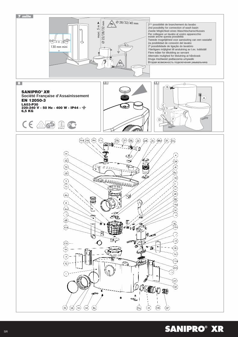
SANIPRO® XR
Société Française d’AssainissementEN 12050-3LA03-P30220-240 V - 50 Hz - 400 W - IP44 - 6,5 KG
12
SR