Embed Size (px)
Citation preview

NOTICE TO CONTRACTORS,
PROPOSAL,
AGREEMENT, &
SPECIAL PROVISIONS
Development Services Department/Engineering Division
Nathan Bray, PE Interim Development Services Director / City Engineer
Proposals shall be delivered to Turlock, California
at or before 2:00 PM on Thursday, February 20, 2020 at the office of the City Engineer,
Development Services: Engineering Division 156 S. Broadway, Suite 150
Turlock, CA 95380
Bid Set January 21, 2020
Contact Person: Adam Hutchings, PE
Phone: (209) 668 5428
FOR CONSTRUCTION ON Project No: 19-50
Sanitary Sewer Lift Stations 9, 42 & 55 Upgrade
IN STANISLAUS COUNTY, TURLOCK, CALIFORNIA.

i
TABLE OF CONTENTS NOTICE TO CONTRACTORS ................................................................................................................. 1
PROPOSAL .................................................................................................................................................. 4 BIDDING FORM ....................................................................................................................................... 5 INFORMATION REQUIRED OF BIDDER ................................................................................................ 9 BIDDER’S BOND .................................................................................................................................... 11
AGREEMENT ............................................................................................................................................. 14 1. Contract Documents .............................................................................................................. 14 2. Term ...................................................................................................................................... 15 3. Scope of Work ....................................................................................................................... 15 4. Contract Price ........................................................................................................................ 15 5. Time for Performance ............................................................................................................ 16 6. Termination ............................................................................................................................ 18 7. Liability for Breach ................................................................................................................. 18 8. Compensation ....................................................................................................................... 19 9. Disputes Pertaining to Payment for Work ............................................................................. 19 10. Permits and Care of Work ..................................................................................................... 20 11. Public Works and Payment of Prevailing Wage .................................................................... 20 12. Superintendence by Contractor............................................................................................. 21 13. Inspection and Testing by City .............................................................................................. 21 14. Conformity with Law and Safety ............................................................................................ 21 15. Other Contracts ..................................................................................................................... 22 16. Bonds .................................................................................................................................... 22 17. Indemnification ...................................................................................................................... 22 18. Contractor's Insurance .......................................................................................................... 22 19. Ownership of Work Product .................................................................................................. 24 20. Taxes ..................................................................................................................................... 25 21. Independent Contractor ......................................................................................................... 25 22. Contractor Not Agent ............................................................................................................. 25 23. Arbitration of Disputes ........................................................................................................... 25 24. Provisions Cumulative ........................................................................................................... 26 25. Notices ................................................................................................................................... 26 26. City Contract Administrator ................................................................................................... 27 27. Interpretation ......................................................................................................................... 27 28. Antitrust Claims ..................................................................................................................... 27 29. Use of City Project Number ................................................................................................... 27 30. No Conflict of Interest ............................................................................................................ 27 31. Confidentiality ........................................................................................................................ 27 32. Modification ........................................................................................................................... 27 33. Waiver ................................................................................................................................... 28 34. Assignment ............................................................................................................................ 28 35. Authority ................................................................................................................................ 28 36. Governing Law ...................................................................................................................... 28 37. Severability ............................................................................................................................ 28 38. Counterparts .......................................................................................................................... 28 39. Mandatory and Permissive .................................................................................................... 28 40. Headings ............................................................................................................................... 28 41. Attorney’s Fees and Costs .................................................................................................... 28 42. Necessary Acts and Further Assurances .............................................................................. 29

ii
SPECIAL PROVISIONS ............................................................................................................................. 41 SECTION 1 - SPECIFICATIONS AND PLANS ...................................................................................... 41
1.01 SPECIFICATIONS: ............................................................................................................... 41 1.02 CONTRACTOR’S RESPONSIBILITY: .................................................................................. 42 1.03 COMPLETENESS AND ACCURACY OF PLANS AND SPECIFICATIONS: ....................... 42
SECTION 2 - PROPOSAL REQUIREMENTS AND CONDITIONS ....................................................... 42 2.01 GENERAL: ............................................................................................................................ 42 2.02 EXISTING UTILITIES, FACILITIES, AND SITE CONDITIONS: ........................................... 43 2.03 ESCROW BID DOCUMENTS ............................................................................................... 43
SECTION 3 - AWARD AND EXECUTION OF CONTRACT .................................................................. 45 3.01 GENERAL: ............................................................................................................................ 45 3.02 BID PROTEST:...................................................................................................................... 46
SECTION 4 - BEGINNING OF WORK, TIME OF COMPLETION AND DELAY DAMAGES ................. 46 SECTION 5 - GENERAL ........................................................................................................................ 46
5.01 LABOR NONDISCRIMINATION: .......................................................................................... 46 5.02 PREVAILING WAGE: ............................................................................................................ 47 5.03 REMOVAL OF ASBESTOS AND HAZARDOUS SUBSTANCES: ....................................... 47 5.04 SUBCONTRACTING: ............................................................................................................ 47 5.05 PROMPT PROGRESS PAYMENT TO SUBCONTRACTORS: ............................................ 48 5.06 PROMPT PAYMENT OF FUNDS WITHHELD TO SUBCONTRACTORS: .......................... 48 5.07 PAYMENTS: .......................................................................................................................... 48 5.08 GUARANTY: .......................................................................................................................... 48 5.09 PUBLIC SAFETY: ................................................................................................................. 48 5.10 SOUND CONTROL REQUIREMENTS: ................................................................................ 49 5.11 WORKING HOURS: .............................................................................................................. 50 5.12 UNDERGROUND SERVICE ALERT REQUIREMENTS: ..................................................... 50 5.13 DUST CONTROL: ................................................................................................................. 50 5.14 WATERING: .......................................................................................................................... 50 5.16 PROGRESS SCHEDULE: .................................................................................................... 50 5.17 PRESERVATION OF PROPERTY: ...................................................................................... 50 5.18 ORDER OF WORK: .............................................................................................................. 51 5.19 AS-BUILTS: ........................................................................................................................... 51 5.20 SURVEYING: ........................................................................................................................ 51 5.21 TESTING: .............................................................................................................................. 51 5.22 SUBMITTALS: ....................................................................................................................... 52 5.23 CLAIMS AND DISPUTES: .................................................................................................... 53 5.24 PRESERVATION OF EXISTING MONUMENTS: ................................................................. 53 5.25 BUSINESS LICENSE: ........................................................................................................... 53 5.26 INTERNET BASED CONSTRUCTION MANAGEMENT SYSTEM: ..................................... 54
SECTION 6 - DESCRIPTION OF WORK ............................................................................................... 56 SECTION 7 - CONSTRUCTION DETAILS ............................................................................................ 56 SECTION 8 - BID ITEM DESCRIPTIONS .............................................................................................. 57
TECHNICAL SPECIFICATIONS ................................................................................................................ 59
DIVISION 01 – GENERAL REQUIREMENTS
011100 COORDINATION OF WORK, PERMITS, AND REGULATIONS 012000 MEASUREMENT AND PAYMENT 013216 CPM CONSTRUCTION SCHEDULE REQUIREMENTS 013233 PRECONSTRUCTION DIGITAL AUDIO-VIDEO DOCUMENTATION 015100 CONSTRUCTION FACILITIES AND TEMPORARY CONTROLS 015526 TRAFFIC REGULATION 015721 STORM WATER RUNOFF CONTROL FOR SITES

iii
017410 CLEANING DURING CONSTRUCTION AND FINAL CLEANING 019310 OPERATION AND MAINTENANCE MANUALS
DIVISION 02 – EXISTING CONDITIONS
020120 PROTECTING EXISTING UNDERGROUND UTILITIES 020130 CONNECTIONS TO EXISTING BURIED PIPELINES 023219 SUBSURFACE UTILITY LOCATING (POTHOLING) 024100 EQUIPMENT, PIPING, AND MATERIALS DEMOLITION
DIVISION 03 – CONCRETE
030500 GENERAL CONCRETE CONSTRUCTION 034220 PRECAST CONCRETE VAULTS 034230 PRECAST CIRCULAR CONCRETE MANHOLES AND WET WELLS
DIVISION 05 – METALS
050520 BOLTS, WASHERS, ANCHORS, AND EYEBOLTS 055300 GRATING, COVER PLATES, AND ACCESS HATCHES
DIVISION 09 – FINISHES
099000 PAINTING AND COATING 099752 COLD-APPLIED WAX TAPE COATING 099754 POLYETHYLENE SHEET ENCASEMENT (AWWA C105) 099761 FUSION-BONDED EPOXY LININGS AND COATINGS
DIVISION 22 – PLUMBING
221329 PUMP CONTROL SYSTEMS
DIVISION 26 – ELECTRICAL
260500 GENERAL ELECTRICAL REQUIREMENTS 260519 WIRES AND CABLES LESS THAN 600 VOLTS 260526 GROUNDING AND BONDING 260534 CONDUITS, BOXES, AND FITTINGS
DIVISION 31 – EARTHWORK
312300 EARTHWORK 312316 TRENCHING, BACKFILLING, AND COMPACTING 312323 FLOWABLE FILL
DIVISION 32 – EXTERIOR IMPROVEMENTS
321216 ASPHALT CONCRETE PAVING 321613 CONCRETE CURBS, GUTTERS, AND SIDEWALKS
DIVISION 33 – UTILITIES
330130 LEAKAGE AND INFILTRATION TESTING 330134 SEWER AND MANHOLE WASTEWATER BYPASS PUMPING 333112 PVC GRAVITY SEWER PIPE
DIVISION 40 – PROCESS INTEGRATION
400500 GENERAL PIPING REQUIREMENTS

iv
400515 PRESSURE TESTING OF PIPING 400520 MANUAL, CHECK, AND PROCESS VALVES 400722 FLEXIBLE PIPE COUPLINGS AND EXPANSION JOINTS 400762 WALL PIPES, SEEP RINGS, AND PENETRATIONS 402040 DUCTILE-IRON PIPE 402092 PVC DISTRIBUTION PIPE (AWWA C900)
DIVISION 43 – PROCESS GAS AND LIQUID HANDLING, PURIFICATION AND STORAGE EQUIPMENT
432140 SUBMERSIBLE RAW WASTEWATER PUMPS

1
CITY OF TURLOCK, CALIFORNIA NOTICE TO CONTRACTORS
Sealed proposals will be received by the City Engineer of the City of Turlock, Development Services/Engineering Division, 156 S. Broadway, Suite 150, Turlock, California 95380, until 2:00 PM on Thursday, February 20, 2020, for:
City Project No. 19-50 Sanitary Sewer Lift Stations 9, 42 & 55 Upgrade
In accordance with and as described and provided in the plans, specifications and the proposed form of contract therefore, all of which are on file in the office of the City Engineer, and to which special reference is hereby made. No verbal, telegraphic, electronic mail, facsimile, or telephone Proposals shall be considered. Proposals are required to be complete and for the entire work, materials and improvements unless the contrary is indicated in the specifications. In accordance with the provisions of California Business and professions Code, Section 7028, Contractor shall possess one of the following Contractor license(s) at the time of bid and for the duration of the contract:
A-General Engineering Contractor Failure to possess the specified license(s) shall render the Bid as non-responsive, shall act as a bar to award of the contract to any Bidder not possessing said license(s) at the time of Bid opening and shall result in the forfeiture of the security of said Bidder. Furthermore, any Bidder or Contractor not so licensed shall be subject to all legal penalties imposed by law, including, but not limited to, any appropriate disciplinary action by the Contractor’s License Board. A mandatory pre-bid meeting will be held on site at the Turlock Regional Water Quality Control Facility at 901 S. Walnut Road at 10:00 AM on Monday, February 10, 2020). Attendance is mandatory for bidders submitting a bid on the project. Each proposal must be accompanied by cash, cashier's check, or check certified by a responsible bank, or by a bid bond, the proposed form of which is on file in the office of the City Engineer of said City and to which special reference is hereby made in a sum not less than ten percent (10%) of the total amount bid, payable to the City of Turlock as liquidated damages in the case the bidder is awarded the contract and fails within ten (10) days after the date of mailing to him by the City Engineer of a notice of award of the contract and that the contract is ready for signature to execute the above-mentioned written contract and file with the City Engineer satisfactory insurance certificates as required by the terms of said contract and satisfactory bonds as required by law for the faithful performance of said contract and for the protection of material, men and laborers. Special reference is hereby made to Sections 5100, et. seq., of the Public Contracts Code of the State of California and to the proposed forms for said bonds now on file in the office of the said City Engineer for further particulars regarding bonds. Pursuant to Section 1773 of the Labor Code, the general prevailing wage rates in the county Stanislaus in which the work is to be done have been determined by the Director of the California Department of Industrial Relations. These wages are set forth in the General Prevailing Wage Rates for this project, available at 156 S. Broadway St, Turlock, CA 95380 and available from the California Department of Industrial Relations’ Internet web site at http://www.dir.ca.gov/DLSR/PWD.

2
Bidders' attention is directed to the insurance requirements in the contract. It is highly recommended that bidders confer with their respective insurance carriers or brokers to determine in advance of bid submission the availability of insurance certificates and endorsements prescribed and provided herein. If an apparent low bidder fails to comply strictly with the insurance requirements, that bidder may be disqualified from award of the contract. No proposal will be considered unless made on forms furnished by the City Engineer of said City at his office of said City. Each proposal must be sealed, and the envelope containing the same must be addressed to the City Engineer of the City of Turlock and must be plainly marked. Each proposal shall clearly identify the bidders name and address on the sealed envelope. Each bid shall separately state in figures the price offered for the approximate quantity of each item set forth and shall also state in words and figures the total contract price. Quantities set forth in the proposal form and in the specifications are approximate only, being given as a basis for comparison of bids, and the City of Turlock does not expressly or implied agree that the actual amount of work or materials will correspond therewith, but reserves the right to increase or decrease the amount of any class or portion of the work or materials as may be deemed necessary by the City Engineer. Proposals may not be withdrawn for a period of sixty (60) days after the time fixed for opening of proposals. The City Council of the City of Turlock reserves the right to reject any and all proposals or any part thereof and to waive any errors or informalities in any proposals and to set and act as sole judge of the merit and qualifications of the equipment, supplies or services offered. At the request and expense of Contractor, pursuant to Division 2, Part 5, Section 22300, et. seq., of the Public Contracts Code, securities equivalent to any funds withheld as retention from progress payments made under this contract may be deposited with the City of Turlock or with a State or Federally chartered bank as escrow agent, who shall pay such moneys to Contractor upon completion of the contract. Copies of the Contract Documents, including Instructions to Bidders, Bid Proposal forms, Plans and Specifications, may be downloaded from the engineering division’s web site or purchased for a non-refundable fee of Sixty Five Dollars ($65.00) at the Office of the City Engineer, 156 S. Broadway, Ste. 150, Turlock, CA 95380, Phone (209) 668-5520. For additional information, go to http://www.CityofTurlock.org/capitalprojects The U.S. Department of Transportation (DOT) provides a toll-free “hotline” service to report bid rigging activities. Bid rigging activities can be reported Mondays through Fridays, between 8:00 a.m. and 5:00 p.m., Eastern Time, Telephone No. 1-800-424-9071. Anyone with knowledge of possible bid rigging, bidder collusion, or other fraudulent activities should use the “hotline” to report these activities. The “hotline” is part of the DOT’s continuing effort to identify and investigate highway construction contract fraud and is operated under the direction of the DOT Inspector General. All information will be treated confidentially and caller anonymity will be respected. No contractor or subcontractor may be listed on a bid proposal for a public works unless registered with the Department of Industrial Relations pursuant to Labor Code Section 1725.5. No contractor or subcontractor may be awarded a contract for public work on a public works unless registered with the Department of Industrial Relations pursuant to Labor Code Section 1725.5. This project is subject to compliance monitoring and enforcement by the Department of Industrial Relations. The contractors and subcontractors must furnish electronic certified payroll records to the Labor Commissioner.
3
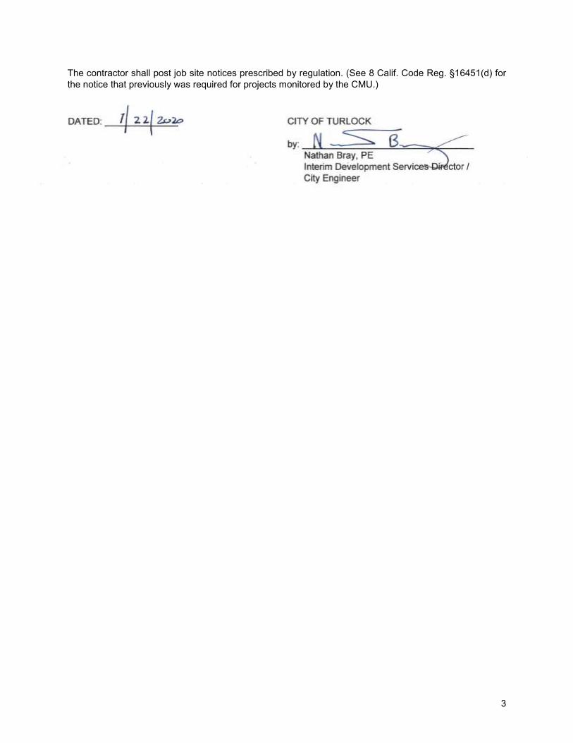
Nathan Bray, PE Interim Development Services Director / City Engineer
The contractor shall post job site notices prescribed by regulation. (See 8 Calif. Code Reg. §16451(d) for the notice that previously was required for projects monitored by the CMU.) DATED: ______________ CITY OF TURLOCK by: _________________________________

4
PROPOSAL
City Project No. 19-50 Sanitary Sewer Lift Stations 9, 42 & 55 Upgrade
City of Turlock, California DATED: to: The Honorable City Council of the City of Turlock, California: NAME OF BIDDER: BUSINESS ADDRESS: PLACE OF RESIDENCE: Bids are to be submitted for the entire work. The amount of the bid for comparison purposes will be the total of all items. The bidder shall set forth for each unit basis item of work a unit price and a total for the item, and for each lump sum item a total for the item, all in clearly legible figures in the respective spaces provided for that purpose. In the case of unit basis items, the amount set forth under the “Item total” column shall be the product of the unit price bid and the estimated quantity for the item. in case of discrepancy between the unit price and the total set forth for a unit basis item, the unit price shall prevail except as provided in (a) or (b), as follows: (a) If the amount set forth as unit price is unreadable or otherwise unclear, or is omitted, or is the same as the amount as the entry in the item total column, then the amount set forth in the item total column for the item shall prevail and shall be divided by the estimated quantity for the item and the price thus obtained shall be the unit price; (b) (Decimal Errors) If the product of the entered unit price and the estimated quantity is exactly off by a factor of ten, one hundred, etc., or one-tenth, or one-hundredth, etc. from the entered total, the discrepancy will be resolved by using the entered unit price or item total, whichever most closely approximates percentage wise the unit price or item total in the Department’s Final Estimate of cost. The Contractor shall submit the following at the time of Bid in order for the Bid to be considered responsive:
• Completed Proposal, pages 4 – 13 . In accordance with the annexed Notice to Contractors, the undersigned, as bidder, declares that he has carefully examined the location of the proposed work, the plans, specifications and technical requirements therefore, and the proposed forms of contract and bonds mentioned or referred to in said Notice and on file in the office of the City Engineer of the City of Turlock, together with the prevailing rate of per diem wages for each craft or type of workmen needed to execute said contract; and he proposes and agrees that if this proposal is accepted, he will furnish all labor, materials, equipment, plant transportation, service, sales taxes, permit fees and other costs necessary to complete the construction in strict conformity to the plans and specifications and he will enter into a written contract with the City of Turlock in the form of contract on file in the Office of the City Engineer for such purposes, and that he will execute and/or provide all bonds and insurance certificates required by law and/or by said contract and/or mentioned in said Notice to Contractors all in accordance with and subject to all applicable laws, and that he will take in full payment therefore the following unit prices, to wit:
5
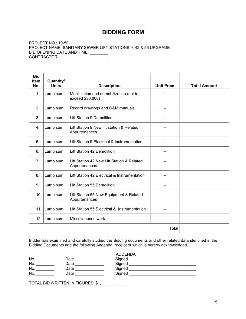
BIDDING FORM PROJECT NO.: 19-50 PROJECT NAME: SANITARY SEWER LIFT STATIONS 9, 42 & 55 UPGRADE BID OPENING DATE AND TIME: ________ CONTRACTOR:______________________
Bid Item No.
Quantity/ Units Description Unit Price Total Amount
1. Lump sum Mobilization and demobilization (not to exceed $30,000)
--
2. Lump sum Record drawings and O&M manuals --
3. Lump sum Lift Station 9 Demolition --
4. Lump sum Lift Station 9 New lift station & Related Appurtenances
--
5. Lump sum Lift Station 9 Electrical & Instrumentation --
6. Lump sum Lift Station 42 Demolition --
7. Lump sum Lift Station 42 New Lift Station & Related Appurtenances
--
8. Lump sum Lift Station 42 Electrical & Instrumentation --
9. Lump sum Lift Station 55 Demolition --
10. Lump sum Lift Station 55 New Equipment & Related Appurtenances
--
11. Lump sum Lift Station 55 Electrical & Instrumentation --
12. Lump sum Miscellaneous work --
Total
Bidder has examined and carefully studied the Bidding documents and other related data identified in the Bidding Documents and the following Addenda, receipt of which is hereby acknowledged.
ADDENDA No. ________ Date _____________ Signed ______________________________ No. ________ Date _____________ Signed ______________________________ No. ________ Date _____________ Signed ______________________________ No. ________ Date _____________ Signed ______________________________ TOTAL BID WRITTEN IN FIGURES: $_, _ _ _ , _ _ _. _ _

6
TOTAL BID WRITTEN IN WORDS: ______________________________________________ COMPANY'S NAME: ______________________________________________________ BY: __________________________________________________________________ ADDRESS: _______________________________________________________________
(Number) (Street)
____________________________________________________________ (City) (State) (ZIP)
CONTRACTOR'S PHONE #:________________________________________________ NOTE: CONTRACTOR WILL BE REQUIRED TO LIST THEIR LICENSE NUMBER, EXPIRATION DATE, AND APPROPRIATE STATEMENT REGARDING PERJURY AND SIGNED BY INDIVIDUAL AUTHORIZED TO DO SO. FAILURE TO INCLUDE THE ABOVE ITEMS MAY CAUSE SAID CONTRACTOR'S BID TO BE REJECTED. , Contractor's License # , Class__ (Company's Name) Expires . DIR #:______________________ This information is true, is provided as per Section 7028.15 of the Business and Professions Code, and is made herein under penalty of perjury. ____________________________________________________________________ (Bidder's Signature) (Date) If the proposal is accepted and the undersigned shall fail to contract as aforesaid and fail to file with the City insurance certificates as required by said contract, within fourteen (14) days after the bidder has received notice from the City Engineer or his representative of the City of Turlock that the contract has been awarded to bidder and is ready for signature, the City of Turlock may, at its option, determine that the bidder has abandoned his contract, and thereupon this proposal and the acceptance thereof shall be null and void. Also accompanying this proposal is an affidavit of noncollusion and questionnaire to general contractors, a statement of proposed subcontractors, if any, the address of mill, shop or office of any subcontractor, and a statement of work to be performed by subcontractors. The names and addresses of persons interested in the foregoing proposal as principals are as follows: (IMPORTANT NOTICE: If bidder or other interested person is a corporation, state legal name of corporation, also names of the president, secretary, treasurer, and manager thereof; if a partnership, state true name of firm, also names of all individual copartners composing firm; if bidder or other interested person is an individual, state first and last name in full.) Licensed in accordance with an act providing for the registration of Contractors, License No. Expiration Date .

7
DATED: , 20 Address: Phone: Signature of Bidder NOTE: If bidder is a corporation, the legal name of the corporation shall be set forth above together with the signature of the officers authorized to sign contracts on behalf of the corporation; if bidder is a co partnership, the true name of the firm shall be set forth above together with the signature of the partner or partners authorized to sign contracts in behalf of the co partnership; and, if bidder is an individual, his signature shall be placed above. If a signature is by an agent other than an officer of a corporation or a member of the partnership, a Power of Attorney must be on file with the City Clerk prior to opening or submitted with the bid; otherwise, the bid will be disregarded as irregular and unauthorized.

8
AFFIDAVIT The undersigned bidder, being first duly sworn, deposes and says that he/she are the party making the foregoing proposal or bid, that this bid is genuine and not collusive or sham, that said bidder has not colluded, conspired, connived or agreed, directly or indirectly, with any other person or bidder, to put in a sham bid, or that said other person shall refrain from bidding, and has not in any manner sought by collusion to secure any advantage against the said City or any person interested in said improvement, for him/herself or any other person. Signature of Bidder Jurat (Government Code Section 8202) State of California County of Subscribed and sworn to (or affirmed) before me on this day of , 20 by proved to me on the basis of satisfactory evidence to be the person(s) who appeared before me. (AFFIX SEAL) NOTARY PUBLIC SIGNATURE NOTARY PUBLIC PRINTED NAME

9
INFORMATION REQUIRED OF BIDDER The bidder is required to provide the following information. Additional sheets may be attached if necessary. Contractor's mailing address: Contractor's telephone number: Number of years’ experience as a contractor in construction work or installation work similar to that required in these specifications: Name of person who inspected the site of the proposed work for your firm: Date of Inspection: List at least four projects of comparable size and scope completed as of recent date: Project No. and Title: ______________________________________________ Class and Type of Work: ______________________________________________ Name, Address, and Phone No. of Owner ______________________________________________ Registered Engineer in Charge of Project: ______________________________________________ Total Contract Amount: ______________________________________________ Contract Amount You Performed: ______________________________________________ Name of Prime Contractor if you were Sub: ______________________________________________ Date Completed: ______________________________________________ Liquidated Damages Assessed: ______________________________________________ Project No. and Title: ______________________________________________ Class and Type of Work: ______________________________________________ Name, Address, and Phone No. of Owner ______________________________________________ Registered Engineer in Charge of Project: ______________________________________________ Total Contract Amount: ______________________________________________ Contract Amount You Performed: ______________________________________________ Name of Prime Contractor if you were Sub: ______________________________________________ Date Completed: ______________________________________________ Liquidated Damages Assessed: ______________________________________________ Project No. and Title: ______________________________________________ Class and Type of Work: ______________________________________________ Name, Address, and Phone No. of Owner ______________________________________________ Registered Engineer in Charge of Project: ______________________________________________ Total Contract Amount: ______________________________________________ Contract Amount You Performed: ______________________________________________ Name of Prime Contractor if you were Sub : _____________________________________________ Date Completed: ______________________________________________

10
Liquidated Damages Assessed: ______________________________________________ Project No. and Title: ______________________________________________ Class and Type of Work: ______________________________________________ Name, Address, and Phone No. of Owner ______________________________________________ Registered Engineer in Charge of Project: ______________________________________________ Total Contract Amount: ______________________________________________ Contract Amount You Performed: ______________________________________________ Name of Prime Contractor if you were Sub : _____________________________________________ Date Completed: ______________________________________________ Liquidated Damages Assessed: ______________________________________________
11
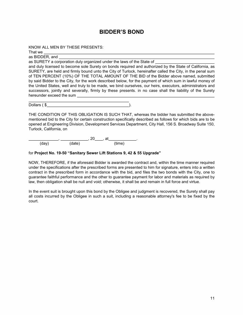
BIDDER’S BOND KNOW ALL MEN BY THESE PRESENTS: That we as BIDDER, and as SURETY a corporation duly organized under the laws of the State of and duly licensed to become sole Surety on bonds required and authorized by the State of California, as SURETY, are held and firmly bound unto the City of Turlock, hereinafter called the City, in the penal sum of TEN PERCENT (10%) OF THE TOTAL AMOUNT OF THE BID of the Bidder above named, submitted by said Bidder to the City, for the work described below, for the payment of which sum in lawful money of the United States, well and truly to be made, we bind ourselves, our heirs, executors, administrators and successors, jointly and severally, firmly by these presents. in no case shall the liability of the Surety hereunder exceed the sum Dollars ( $ ). THE CONDITION OF THIS OBLIGATION IS SUCH THAT, whereas the bidder has submitted the above-mentioned bid to the City for certain construction specifically described as follows for which bids are to be opened at Engineering Division, Development Services Department, City Hall, 156 S. Broadway Suite 150, Turlock, California, on , , 20 , at . (day) (date) (time) for Project No. 19-50 “Sanitary Sewer Lift Stations 9, 42 & 55 Upgrade” NOW, THEREFORE, if the aforesaid Bidder is awarded the contract and, within the time manner required under the specifications after the prescribed forms are presented to him for signature, enters into a written contract in the prescribed form in accordance with the bid, and files the two bonds with the City, one to guarantee faithful performance and the other to guarantee payment for labor and materials as required by law, then obligation shall be null and void; otherwise, it shall be and remain in full force and virtue. In the event suit is brought upon this bond by the Obligee and judgment is recovered, the Surety shall pay all costs incurred by the Obligee in such a suit, including a reasonable attorney's fee to be fixed by the court.

12
IN WITNESS WHEREOF, we have hereunto set our hands and seals on this day of , 201 . BIDDER (SEAL) (Bidder’s Name and Corporate Seal) (Signature) (Print Name and Title) (ATTACH ACKNOWLEDGMENT OF BIDDER) SURETY (SEAL) (Surety’s Name and Corporate Seal) (Signature) (Print Name and Title) (ATTACH ACKNOWLEDGMENT OF SURETY'S ATTORNEY-IN-FACT) NOTE: ATTACH CERTIFIED COPY OF POWER OF ATTORNEY
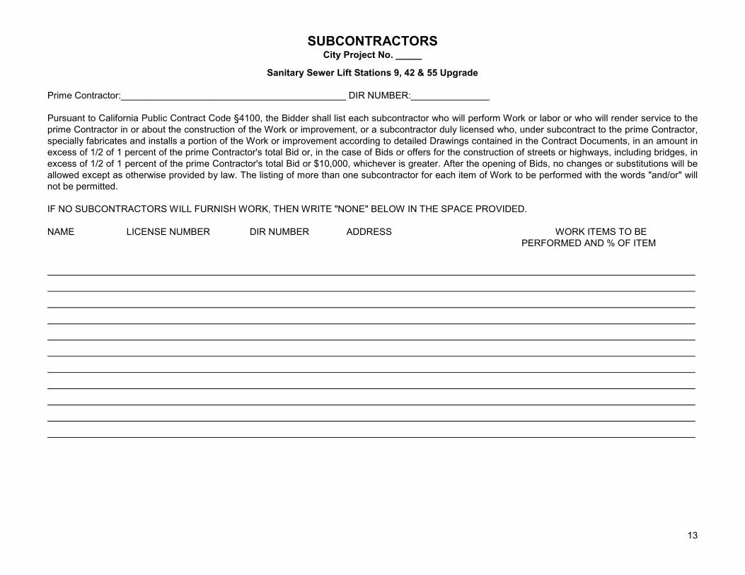
SUBCONTRACTORS City Project No. _____
13
Sanitary Sewer Lift Stations 9, 42 & 55 Upgrade
Prime Contractor:___________________________________________ DIR NUMBER:_______________ Pursuant to California Public Contract Code §4100, the Bidder shall list each subcontractor who will perform Work or labor or who will render service to the prime Contractor in or about the construction of the Work or improvement, or a subcontractor duly licensed who, under subcontract to the prime Contractor, specially fabricates and installs a portion of the Work or improvement according to detailed Drawings contained in the Contract Documents, in an amount in excess of 1/2 of 1 percent of the prime Contractor's total Bid or, in the case of Bids or offers for the construction of streets or highways, including bridges, in excess of 1/2 of 1 percent of the prime Contractor's total Bid or $10,000, whichever is greater. After the opening of Bids, no changes or substitutions will be allowed except as otherwise provided by law. The listing of more than one subcontractor for each item of Work to be performed with the words "and/or" will not be permitted. IF NO SUBCONTRACTORS WILL FURNISH WORK, THEN WRITE "NONE" BELOW IN THE SPACE PROVIDED. NAME LICENSE NUMBER DIR NUMBER ADDRESS WORK ITEMS TO BE PERFORMED AND % OF ITEM

14
AGREEMENT
FOR PUBLIC IMPROVEMENT
City Project No. 19-50
Sanitary Sewer Lift Stations 9, 42 & 55 Upgrade THIS PUBLIC IMPROVEMENT AGREEMENT (the “Agreement”) is entered into by and between the CITY OF TURLOCK, a California municipal corporation (“City”), and ________________, a ______________ (“Contractor”), on this ____ day of _________ 20__ (the “Effective Date”). City and Contractor may be collectively referred to herein as the “Parties” or individually as “Party.” There are no other parties to this Agreement. RECITALS
A. City seeks a duly qualified and licensed firm experienced in the construction of Project No. 19-50, “Sanitary Sewer Lift Stations 9, 42 & 55 Upgrade” (the “Project”).
B. The Project involves the expenditure of funds in excess of $5,000 and constitutes a “public project” pursuant to Public Contract Code section 20161.
C. Contractor has made a proposal to City to provide construction services, a copy of which is attached and incorporated hereto as Exhibit A (the “Services”).
D. City has determined it is necessary and desirable to employ the services of Contractor to perform construction work on the Project.
E. City has taken appropriate proceedings to authorize construction of the Project and execution of this contract pursuant to Public Contract Code section 20160 et seq.; specifically, on _____________, 20___, at a duly noticed meeting of the City Council of the City of Turlock, this contract for the construction of the improvements hereinafter described was awarded to Contractor as the lowest responsive and responsible bidder for said improvements. NOW, THEREFORE, in consideration of the promises and covenants set forth below, the Parties agree as follows:
AGREEMENT 1. Contract Documents
This Agreement, together with the following documents, are collectively referred to herein as the “Contract Documents”:
i. Notice to Bidders; ii. Contractor’s Bid or Proposal accepted by City; iii. General Conditions, Supplementary Conditions, and Special Provisions of the City of Turlock for
Project No. 19-50, “Sanitary Sewer Lift Stations 9, 42 & 55 Upgrade;” iv. Plans and detailed drawings prepared for this Project and approved by City (“Project Plans”); v. All bonds and insurance required by the Contract Documents; vi. Any and all supplemental agreements amending, decreasing, or extending the work contemplated
or which may be required to complete the work in a substantial and acceptable manner; and vii. The current edition of the City of Turlock Standard Specifications and Drawings.
All of the Contract Documents are intended to incorporate the terms of the others so that any work called for in one and not mentioned in the other, or vice versa, is to be executed the same as if mentioned in all said

15
documents. The documents comprising the complete contract will hereinafter be referred to as the “Contract.” In case of any dispute regarding the terms of the Contract, the decision of the City Engineer shall be final. 2. Term
The Contract shall be effective as of the Effective Date first stated above. Contractor shall not commence work on the Project until it has been given notice by City (“Notice to Proceed”). The Contract shall terminate one (1) year after City accepts Contractor’s performance of the Services (the “Term”), unless the Parties mutually agree in writing to terminate the Contract earlier or extend the Term in an agreed writing executed by both Parties. 3. Scope of Work
(a) Services. Contractor shall perform the Services described in Exhibit A, subject to all terms and conditions in the Contract. Contractor shall not receive additional compensation for the performance of any Services not described therein.
(b) Modification. City, at any time, by written order, may make changes within the general scope of the work under this Agreement or issue additional instructions, require additional work or direct deletion of work. Contractor shall not proceed with any change involving an increase or decrease in the Contract Price, as defined in Section 4 of this Agreement, or the Completion Schedule without prior written authorization from City. Contractor shall not be entitled to compensation for the performance of any such unauthorized work. Contractor further waives any and all right or remedy by way of restitution or quantum meruit for any and all extra or changed work performed without express and prior written authorization of City. Notwithstanding the foregoing, Contractor shall promptly commence and diligently complete any change to the work subject to City's written authorization issued pursuant to this Section ; Contractor shall not be relieved or excused from its prompt commencement of diligent completion of any change subject to City's written authorization by virtue of the absence or inability of Contractor and City to agree upon the extent of any adjustment to the Completion Schedule or Contract Price on account of such change. The issuance of a Change Order pursuant to this Section 3 in connection with any change authorized by City shall not be deemed a condition precedent to Contractor's obligation to promptly commence and diligently complete any such change authorized by City hereunder. City's right to make changes shall not invalidate the Contract nor relieve Contractor of any liability or other obligations under the Contract. Any requirement of notice of changes in the scope of work to Contractor’s surety shall be the responsibility of Contractor.
(c) Specific Materials & Performance of Work. Contractor shall furnish all tools, equipment, facilities, labor, and materials necessary to perform and complete, in good workmanlike manner, the work of general construction as called for and in the manner designated in, and in strict conformity with, the plans and specifications for said work entitled, “General Conditions and Special Provisions for Project No. 19-50, Sanitary Sewer Lift Stations 9, 42 & 55 Upgrade.” The equipment, apparatus, facilities, labor, and material shall be furnished, and said work performed and completed as required by the Contract under the direction and supervision, and subject to the approval, of the City Engineer of or City Engineer’s designated agent.
(d) Exhibits. All “Exhibits” referred to below or attached hereto are, by this reference, incorporated into the Contract.
Exhibit Designation Exhibit Title 1. Exhibit A Scope of Services 2. Exhibit B Payment by Force Account 3. Exhibit C Workers’ Compensation Insurance Certification 4. Exhibit D Performance Bond 5. Exhibit E Payment Bond
4. Contract Price
City shall pay, and Contractor shall accept in full payment for the work set forth above in Section 3, Scope of Work, an amount not to exceed _______________________ Dollars ($___________.00) (the “Contract Price”). Said amount shall be paid pursuant to Section 8 of this Agreement. The Contract Price may only be

16
changed by a contract change order. The value of any work covered by a contract change order for an adjustment in the Contract Price will be determined in the sole discretion of City as follows:
(a) If the work performed is on the basis of unit prices contained in the Contract Documents, the change order will be determined in accordance with the provisions in Section 4-1.05, “Changes and Extra Work”, of the Caltrans Standard Specifications, as applicable; or
(b) If the work performed is not included on the engineer’s estimate associated with a unit price, the change order will be by a mutually agreed lump sum; or
(c) If the change order is not determined as described above in either subdivision (a) or (b), the change order will be determined on the basis of force account in accordance with the provisions set forth in Exhibit B, “Payment by Force Account,” attached hereto and incorporated herein by reference. 5. Time for Performance
The time fixed for the commencement of work under the Contract is within ten (10) working days after the Notice to Proceed has been issued. The work on this project, including all punch list items, shall be completed on or before the expiration of one hundred forty five (145) working days (the “Completion Date”) beginning on the first day of work or no later than the tenth day after the Notice to Proceed has been issued.
(a) Right of City to Increase Working Days: If Contractor fails to complete the Services by the Completion Date, the City Engineer shall have the right to increase the number of working days in the amount the City Engineer may determine will best serve the interests of City, and if the City Engineer desires to increase said number of working days, the City Engineer shall have the further right to charge Contractor and deduct from the final payment for the work the actual cost of engineering, inspection, superintendence, and other overhead expenses which are directly chargeable to Contractor, and which accrue during the period of such extension, except that the cost of the final service and preparation of the final estimates shall not be included in such charges. No extension of time for completion of Services under the Contract shall be considered unless requested by Contractor at least twenty (20) calendar days prior to the Completion Date, in writing, to the City Engineer. The Completion Date may only be changed by a contract change order. The value of any work covered by a contract change order for an adjustment in the Completion Date will be determined as follows:
i. Additional working days will be awarded where the amount of time is mutually agreed upon by Contractor and the City Engineer; or
ii. Additional working days will be awarded where Contractor is prevented from completing
any part of the work identified on the critical path and:
1. where the delay is caused by acts of public enemy, fire, floods, tsunamis, earthquakes, epidemics, quarantine restrictions, strikes, labor disputes, shortage of materials and freight embargos, provided that Contractor shall notify Engineer in writing of the causes of delay within fifteen (15) days from the beginning of that delay; or
2. where the delay is caused by actions beyond the control of Contractor; or 3. where the delay is caused by actions or failure to act by the City Engineer.
Contractor shall not be entitled to an adjustment in the Completion Date for delays within the control of Contractor. Delays resulting from and within the control of a subcontractor or supplier of Contractor shall be deemed to be delays within the control of Contractor.
(b) Excusable Delays. Contractor shall not be in breach of the Contract in the event that performance of Services is temporarily interrupted or discontinued due to a “Force Majeure” event which is defined as: riots, wars, sabotage, civil disturbances, insurrections, or explosions; natural disasters, such as floods, earthquakes, landslides, and fires; strikes, lockouts, and other labor disturbances; or other catastrophic

17
events, which are beyond the reasonable control of Contractor. Force Majeure does not include Contractor’s financial inability to perform, Contractor’s failure to obtain any necessary permits or licenses from other governmental agencies, or Contractor’s failure to obtain the right to use the facilities of any public utility where such failure is due solely to the acts or omissions of Contractor. If Contractor’s performance of the Services is delayed by an excusable delay, the Completion Date shall be extended for such reasonable time as determined by the City Engineer. Extensions in time must be requested by Contractor within fifteen (15) calendar days of the excusable delay in order to receive consideration.
(c) Emergency - Additional Time for Performance - Procurement of Materials. If, because of war or other declared national emergency, the federal or state government restricts, regulates, or controls the procurement and allocation of labor or materials, or both, and if solely because of said restrictions, regulations or controls, Contractor is, through no fault of Contractor, unable to perform the Services, or the work is thereby suspended or delayed, any of the following steps may be taken:
i. City may, pursuant to resolution of the City Council, grant Contractor additional time for the performance of the Contract, sufficient to compensate in time, for delay or suspension.
To qualify for such extension in time, Contractor within ten (10) days of Contractor's discovering such inability to perform, shall notify the City Engineer in writing thereof, and give specific reasons therefore; the City Engineer shall thereupon have sixty (60) days within which to procure such needed materials or labor as is specified in this agreement, or permit substitution, or provide for changes in the work in accordance with subdivision (b) of this Section. Substituted materials, or changes in the work, or both, shall be ordered in writing by the City Engineer, and the concurrence of the City Council shall not be necessary. All reasonable expenses of such procurement incurred by the City Engineer shall be defrayed by the Contractor; or
ii. If such materials or labor cannot be procured through legitimate channels within sixty (60) days after the filing of the aforesaid notice, either Party may, upon thirty (30) days' written notice to the other, terminate this agreement. In such event, Contractor shall be compensated for all work executed upon a unit basis in proportion to the amount of the work completed, or upon a cost-plus-ten-percent (10%) basis, whichever is the lesser. Materials on the ground, in process of fabrication or in route upon the date of notice of termination specially ordered for the Project and which cannot be utilized by Contractor, shall be compensated for by City at cost, including freight, provided Contractor shall take all steps possible to minimize this obligation; or
iii. The City Council, by resolution, may suspend the Contract until the cause of inability to perform is
removed for a period of not to exceed sixty (60) days.
If the Contract is not canceled, and the inability of Contractor to perform continues without fault on Contractor's part, beyond the time during which the Contract may have been suspended, as herein above provided, the City Council may further suspend the Contract, or either Party hereto may, without incurring any liability, elect to declare the Contract terminated upon the ground of impossibility of performance. In the event City declares this agreement terminated, such declaration shall be authorized by the City Council by resolution, and Contractor shall be notified in writing thereof within five (5) days after the adoption of such resolution. Upon such termination, Contractor shall be entitled to proportionate compensation at the Contract Price for such portion of the Contract as may have been performed; or
iv. City may terminate the Contract, in which case Contractor shall be entitled to proportionate
compensation at the agreed rate for such portion of the Contract as may have been performed. Such termination shall be authorized by resolution of the City Council. Notice thereof shall be forthwith given in writing to Contractor, and the Contract shall be terminated upon receipt by Contractor of such notice.
In the event of the termination provided in this sub-paragraph (iv), none of the covenants, conditions or provisions hereof shall apply to the Services not performed, and City shall be liable to Contractor for the proportionate compensation last herein mentioned.

18
(a) Option of City to Terminate Contract for Failure to Complete Services. If a Party should fail to perform any of its obligations hereunder within the time and in the manner herein provided, or otherwise violates any of the terms of the Contract (the “Defaulting Party”), the other Party shall give notice to the Defaulting Party and allow the Defaulting Party ten (10) days to correct such deficiency. If the Defaulting Party does not correct such deficiency, the other Party may immediately terminate the Contract by giving written notice of such termination, stating the reason for such termination. In such event, Contractor shall be entitled to receive payment for all Services satisfactorily rendered until such termination, provided, however, there shall be deducted from such amount the amount of damage, if any, sustained by virtue of any breach of the Contract by Contractor, including Delay Damages. If payment under the Contract is based upon a lump sum in total or by individual task, payment for Services satisfactorily rendered shall be an amount which bears the same ratio to the total fees specified in this Agreement as the Services satisfactorily rendered hereunder by Contractor to the total services otherwise required to be performed for such total fee, provided, however, that there shall be deducted from such amount the amount of damage, if any sustained by City by virtue of any breach of the Contract by Contractor. Upon termination, Contractor shall deliver copies of all Work Product, as defined in Section 19 of this Agreement, to City. If District terminates the Contract before Contractor commences any Services hereunder, City shall not be obligated to make any payment to Contractor.
(b) If Contractor should be adjudged bankrupt or if it should make a general assignment for the benefit of its creditors, or if a receiver should be appointed on account of its insolvency, or if it or any of its subcontractors should violate any of the provisions of the Contract, City may serve written notice upon it and its surety of its intention to terminate the Contract. Such notice shall contain the reasons for City’s intention to terminate the Contract, and unless such violations shall cease within five (5) calendar days after serving of such notice, the Contract shall cease and terminate upon the expiration of said five (5) calendar days. In the event of any such termination, City shall immediately serve written notice thereof upon the surety and Contractor, and the surety shall have the right to take over and perform the Contract; provided however, that, if the surety does not give City written notice of its intention to take over and perform the Contract or does not commence performance thereof within thirty (30) calendar days from the date of the service of such notice, City may take over the work and prosecute the same to completion by contract or any other method it may deem advisable, for the account and at the expense of Contractor, and Contractor and its surety shall be jointly liable to City for any excess cost occasioned City thereby, and in such event City may, without liability for so doing, take possession of and utilize in completing the work, such materials, appliances, and other property belonging to Contractor as may be on the Project site and necessary thereof. 7. Liability for Breach
Neither Party waives the right to recover direct damages against the other for breach of the Contract, including any amount necessary to compensate City for all detriment proximately caused by Contractor's failure to perform its obligations hereunder or which in the ordinary course of things would be likely to result therefrom. City reserves the right to offset such damages against any payments owed to Contractor. City shall not, in any manner, be liable for special or consequential damages, including but not limited to Contractor's actual or projected lost profits had Contractor completed the Services required by the Contract. In the event of
(d) Delay Damages. In the event Contractor, for any reason, fails to perform the Services to the satisfaction of the City Engineer by the Completion Date, City may, in accordance with Section 7203 of the Public Contract Code, in lieu of any other of its rights authorized by Section 6 of this agreement, deduct from payments or credits due Contractor after such breach a sum equal to Seven Hundred Dollars ($700.00) for each calendar day beyond the Completion Date. This deduction shall not be considered a penalty but shall be considered as delay damages. The aforementioned rate of deduction is an amount agreed to by the Parties as reasonably representing additional construction engineering costs incurred by City if Contractor fails to complete the Services by the Completion Date. However, any deduction assessed as delay damages shall not relieve Contractor from liability for any damages or costs resulting from delays to other contractors on the project or other projects caused by a failure of the assessed Contractor to complete the Services by the Completion Date. Due account shall be taken of any time extensions granted to Contractor by City. Permitting Contractor to continue work beyond the Completion Date shall not operate as a waiver on the part of City of any of its rights under the Contract nor shall it relieve Contractor from liability for any damages or costs resulting from delays to other contractors on the project or other projects caused by a failure of the assessed Contractor to complete the Services by the Completion Date. 6. Termination

19
termination by either Party, copies of all finished or unfinished Work Product, as defined in Section 19 of this Agreement, shall become the property of City. Notwithstanding the foregoing, in no event shall City be liable, regardless of whether any claim is based on contract or tort, for any special, consequential, indirect or incidental damages, including, but not limited to, lost profits or revenue, arising out of or in connection with the Contract or the Services performed in connection with the Contract. 8. Compensation
City shall make Payments to Contractor in accordance with the provisions of Section 9 of the General Conditions in legally executed and regularly issued warrants of City, drawn on the appropriate fund or funds as required by law and order of the City Council thereof. Contractor shall be administered a progress payment approximately every thirty (30) calendar days from the time work begins according to the payment schedule furnished by the City Engineer at the time work begins. Contractor shall provide access at all reasonable times to all reports, contract records, contract documents, contract files, and personnel necessary to audit and verify Contractor’s charges to City under this Contract. Monthly progress payments in the amount of 95 percent (95%) of the value of the work will be made to Contractor based on the Contractor’s estimate and the schedule of prices contained in the accepted bid. The remaining 5 percent (5%) will be retained by City as partial security for the fulfillment of the Contract except that at any time after 50 percent (50%) of the work has been completed, if the City Engineer finds that satisfactory progress is being made and the Project’s critical path of work are on schedule, City may discontinue any further retention. Such discontinuance will only be made upon the written request of Contractor. City may, at any time the City Engineer finds that satisfactory progress is not being made, again institute retention of 5 percent (5%) as specified above. Payment will be made as soon as possible after the preparation of the Contractor’s estimate. City shall pay the remaining 5 percent (5%) of the value of the Services completed under this Contract, if unencumbered by retentions for claims, not sooner than the expiration of thirty-five (35) calendar days from the date of acceptance of the work completed by Contractor by the City Council and not later than sixty (60) days from the “completion” of the Services as said term is defined in Public Contract Code section 7107(c). No estimate or payment shall be made if, in the judgment of the City Engineer, the work is not proceeding in accordance with the provisions of the Contract, or when, in his judgment, the total value of the work done since the last estimate amounts to less than $1,000. No progress payments will be made if the time allotted for the job is thirty (30) working days or less. Payment of any progress payment, or the acceptance thereof by Contractor, shall not constitute acceptance of the work performed under this Contractor, or any portion thereof, and shall in no way reduce the liability of Contractor to replace unsatisfactory work or materials, though the unsatisfactory character of such work or materials may not have been apparent or detected at the time such payment was made. Additionally, as a precondition to City’s progress payments hereunder, Contractor shall provide to City, prior to payment, unconditional waivers and releases of stop notices pursuant to Civil Code section 8128 et seq. from each subcontractor and materials supplier. The form of said waivers and releases shall be as set forth in Civil Code section 3262(d)(2). Pursuant to Public Contract Code section 22300 et seq., Contractor may request the right to substitute securities for any moneys withheld by City to ensure the performance required of Contractor under the Contract, or that City make payment of retentions earned directly into an escrow account established at the expense of Contractor. 9. Disputes Pertaining to Payment for Work
Should any dispute arise respecting the true value of any work performed, of any work omitted, or of any extra work which Contractor may be required to do, or respecting the size of any payment to Contractor during the performance of the Contract, such dispute shall be decided by the City Engineer, and the decision of the latter shall be final and conclusive. The Parties agree to comply with the claims resolution procedures set forth in Public Contract Code section 9204 when applicable.

20
(a) Claims Processing. Any submission of a claim by Contractor must comply with the requirements of Public Contract Code section 9204. Upon receipt of a claim pursuant to this section, City shall conduct a reasonable review of the claim and, within a period not to exceed forty-five (45) days, shall provide Contractor a written statement identifying what portion of the claim is disputed and what portion is undisputed. Upon receipt of a claim, the Parties may, by mutual agreement, extend the time period provided in this subdivision. Contractor shall furnish reasonable documentation to support the claim. Any payment due on an undisputed portion of the claim shall be processed and made within sixty (60) days after City issues its written statement. If Contractor disputes City’s written response, or if City fails to respond to a claim issued pursuant to this section within the time prescribed, Contractor may demand in writing an informal conference to meet and confer for settlement of the issues in dispute.
(b) Meet-and-Confer Conference. Upon receipt of a demand in writing sent by registered mail or certified mail, return receipt requested, City shall schedule a meet-and-confer conference within thirty (30) days for settlement of the dispute. Within ten (10) business days following the conclusion of the meet-and-confer conference, if the claim or any portion of the claim remains in dispute, City shall provide the claimant a written statement identifying the portion of the claim that remains in dispute and the portion that is undisputed. Any payment due on an undisputed portion of the claim shall be processed and made within sixty (60) days after the City issues its written statement.
(c) Nonbinding Mediation. Any disputed portion of the claim, as identified by Contractor in writing, shall be submitted to nonbinding mediation, with th Parties sharing the associated costs equally. The Parties shall mutually agree to a mediator within ten (10) business days after the disputed portion of the claim has been identified in writing. If the Parties cannot agree upon a mediator, each party shall select a mediator and those mediators shall select a qualified neutral third party to mediate with regard to the disputed portion of the claim. Each Party shall bear the fees and costs charged by its respective mediator in connection with the selection of the neutral mediator. If mediation is unsuccessful, the parts of the claim remaining in dispute shall be subject judicial review pursuant to Section 23 of this Agreement. Notwithstanding any claim, dispute, or other disagreement between the Parties regarding performance under the Contract, the scope of work hereunder, or any other matter arising out of or related to, in any manner, the Contract, Contractor shall proceed diligently with performance of the Services in accordance with City's written direction, pending any final determination or decision regarding any such claim, dispute, or disagreement. 10. Permits and Care of Work
Contractor shall, at Contractor's expense, obtain all necessary permits and licenses for the construction of each improvement, give all necessary notices and pay all fees and taxes required by law, except those City fees set forth in Section 1 of the Special Provisions. Contractor has examined the Project site and is familiar with its topography and condition, location of property lines, easements, building lines, and other physical factors and limitations affecting the performance of the Contract. Contractor, at Contractor's expense, shall obtain any permission necessary for any operations conducted off the property owned or controlled by City. Contractor shall be responsible for the proper care and protection of all materials delivered and work performed until completion and final acceptance. 11. Public Works and Payment of Prevailing Wage
(a) Monitoring and Enforcement. In accordance with the provisions of Sections 1725.5, 1771.1, 1771.3, and 1771.4 of the Labor Code, all work performed under the Contract is subject to compliance monitoring and enforcement by the Department of Industrial Relations (“DIR”). All work performed by Contractor or its subcontractors under the Contract is subject to the requirements of Labor Code section 1720 et seq. It is not a violation of this section for an unregistered contractor to submit a bid that is authorized by Section 7029.1 of the Business and Professions Code or by Section 10164 or 20103.5 of the Public Contract Code, provided the contractor is registered to perform public work pursuant to Section 1725.5 of the Labor Code at the time the contract is awarded. Contractor and its subcontractors shall furnish the records specified in Section 1776 of the Labor Code directly to the Labor Commissioner, at least monthly, in the format prescribed by the Labor Commissioner. In accordance with the provisions of Section 1773.3 of the Labor Code, City shall provide notice to DIR of the award of this Contract within thirty (30) working days of the award. The notice shall be transmitted

21
electronically in a format specified by DIR and shall include the name of Contractor, any subcontractor listed on the successful bid, the bid and contract award dates, the contract amount, the estimated start and completion dates, Project location, and any additional information DIR specifies that aids in the administration and enforcement of Section 1720 et seq. of the Labor Code.
(b) Wages & Hours of Employment: In the performance of the Services under the Contract, eight (8) hours shall be the maximum hours of labor on any calendar day, and the minimum wages of compensation of persons performing labor in the execution of this agreement shall be the current prevailing scale of wages determined by DIR for the community. Contractor shall forfeit as penalty Twenty-five and no/100ths Dollars ($25.00) to be paid to City for each workman employed in the execution of the Contract by Contractor or its subcontractor(s), for each calendar day during which any workman is required or permitted to labor more than eight (8) hours, in violation of provisions of Labor Code section 1810 et seq. Contractor shall post prevailing wage rates at the Project no later than the first day Contractor commences performance of the Services under the Contract. 12. Superintendence by Contractor
Contractor shall give personal superintendence to the work on the Project or have a competent foreman or superintendent satisfactory to the City Engineer on the Project at all times during construction and performance of work under the Contract, with authority to act for Contractor. 13. Inspection and Testing by City
Contractor shall at all times maintain proper facilities and provide safe access for inspection by City to all parts of the work performed on the Project and to the shops wherein the work is in preparation. Contractor shall notify City with sufficient time in advance of the manufacture of production materials to be supplied by Contractor under the Contract in order for City to arrange for mill or factory inspection and testing of same. Any materials shipped by Contractor from factory prior to having satisfactorily passed such testing and inspection by City's representative or prior to the receipt of notice from such representative that such testing and inspection will not be required shall not be incorporated on the Project. Contractor shall also furnish to City, in triplicate, certified copies of all factory and mill test reports upon request. 14. Conformity with Law and Safety
Contractor shall observe and comply with all applicable laws, ordinances, codes, and regulations of governmental agencies, including federal, state, municipal, and local governing bodies having jurisdiction over any or all of the scope of Services, including all provisions of the Occupational Safety and Health Act of 1979 as amended, all California Occupational Safety and Health Regulations, the California Building Code, the American with Disabilities Act, any copyright, patent, or trademark law, and all other applicable federal, state, municipal, and local safety regulations, appropriate trade association safety standards, and appropriate equipment manufacturer instructions. All Services performed by Contractor or its subcontractors must be in accordance with these laws, ordinances, codes, and regulations. Contractor’s failure to comply with any laws, ordinances, codes, or regulations applicable to the performance of the Services hereunder shall constitute a breach of contract. In cases where standards conflict, the standard providing the highest degree of protection shall prevail. If a death, serious personal injury or substantial property damage occurs in connection with the performance of the Contract, Contractor shall immediately notify City's risk manager by telephone. If any accident occurs in connection with the Contract, Contractor shall promptly submit a written report to City, in such form as City may require. This report shall include the following information: (a) name and address of the injured or deceased person(s); (b) name and address of Contractor’s subcontractor, if any; (c) name and address of Contractor’s liability insurance carrier; and (d) a detailed description of the accident, including whether any of City's equipment, tools, or materials were involved. If a release of a hazardous material, substance, or waste occurs in connection with the performance of the Contract, Contractor shall immediately notify City. Contractor shall not store hazardous materials or hazardous waste within City limits without a proper permit from City.

22
15. Other Contracts
City may award other contracts for additional work on the Project, and Contractor shall fully cooperate with such other contractors and carefully fit Contractor's own work to that provided under other contracts as may be directed by the City Engineer. Contractor shall not commit or permit any act which will interfere with the performance of work by any other contractor. 16. Bonds
Concurrently with the execution hereof, Contractor shall furnish, on the forms provided herein as Exhibits D and E, respectively, corporate surety bonds to the benefit of City, issued by a surety company acceptable to City and authorized and admitted to do business in the state of California, as follows:
(a) Faithful Performance Bond. In an amount equal to at least one hundred percent (100%) of the Contract Price as security for the faithful performance of the Contract. The bond shall contain a provision that the surety thereon waives the provisions of Sections 2819 and 2845 of the Civil Code.
(b) Payment Bond. In an amount equal to at least one hundred percent (100%) of the Contract Price as security for the payment of all persons performing labor and furnishing materials in connection with the Contract. The bond shall be in accordance with the provisions of Sections 3225, 3226, and 3247 through 3252, inclusive, of the Civil Code and Section 13020 of the Unemployment Insurance Code of California. Said bond shall also contain a provision that the surety thereon waives the provisions of Sections 2819 and 2845 of the Civil Code. The surety companies shall familiarize themselves with all provisions and conditions of the Contract. It is understood and agreed that the surety or sureties waive the right of special notification of any modification or alterations, omissions or reductions, extra or additional work, extensions of time, or any other act or acts by City or its authorized agents under the terms of this Contract and failure to so notify the surety or sureties of such changes shall in no way relieve the surety or sureties of their obligations under the Contract. 17. Indemnification
(a) Indemnity for Professional Liability. When the law establishes a professional standard of care for Contractor’s Services, to the fullest extent permitted by law, Contractor shall indemnify, protect, defend, and hold harmless City and any and all of its elective and appointive boards, officers, officials, agents, employees or volunteers (“City’s Agents”) from and against any and all losses, liabilities, damages, costs, and expenses, including legal counsel’s fees and costs but only to the extent Contractor or its subcontractors are responsible for such damages, liabilities and costs on a comparative basis of fault between Contractor or its subcontractors and City in the performance of professional services under the Contract. Contractor shall not be obligated to defend or indemnify City for City’s own negligence or for the negligence of others.
(b) Indemnity for other than Professional Liability. Other than in the performance of professional services and to the full extent permitted by law, Contractor shall indemnify, defend, and hold harmless City and any and City’s Agents from and against any liability, including liability for claims, suits, actions, arbitration proceedings, administrative proceedings, regulatory proceedings, losses, expenses or costs of any kind, whether actual, alleged or threatened, including legal counsel’s fees and costs, court costs, interest, defense costs, and expert witness fees, where the same arise out of, are a consequence of, or are in any way attributable to, in whole or in part, the performance of the Contract by Contractor or by any individual or agency for which Contractor is legally liable, including, but not limited to, officers, agents, employees, or subcontractors of Contractor. 18. Contractor's Insurance
Concurrently with the execution hereof, Contractor shall furnish City with satisfactory proof of carriage of the insurance required under this section, and that Contractor shall give City at least sixty (60) days prior notice of the cancellation of any policy during the Term of this contract. Contractor shall not commence work under this Agreement until Contractor has obtained City’s approval regarding all insurance requirements, forms, endorsements, amounts, and carrier ratings, nor shall Contractor allow any subcontractor to commence work on a subcontract until all similar insurance required of the subcontractor shall have been so obtained and

23
approved. Contractor shall procure and maintain for the duration of the Contract insurance against claims for injuries to persons or damages to property which may arise from or in connection with the performance of the Services hereunder by Contractor, its agents, representatives, employees or subcontractors. Failure to maintain or renew coverage or to provide evidence of renewal may constitute a material breach of the Contract. Any available insurance proceeds in excess of the specified minimum limits and coverage shall be available to City.
(a) General Liability Insurance. Contractor shall maintain commercial general liability insurance with coverage at least as broad as Insurance Services Office form CG 00 01, in an amount not less than Two Million Dollars ($2,000,000) per occurrence, Four Million Dollars ($4,000,000) general aggregate, for bodily injury, personal injury, and property damage, including, without limitation, blanket contractual liability and coverage for explosion, collapse, and underground property damage hazards. Contractor’s general liability policies shall be primary and not seek contribution from City’s coverages and be endorsed using Insurance Services Office form CG 20 10 to provide that City and its officers, officials, employees, and agents shall be additional insureds under such policies. For construction contracts, an endorsement providing completed operations to the additional insured, ISO form CG 20 37, is also required. The policy shall contain, or be endorsed to contain, the following provisions: (1) City, its elective and appointive boards, officers, agents, employees, and volunteers are to be covered as additional insureds with respect to liability arising out of work or operations performed by or on behalf of Contractor, including materials, parts or equipment furnished in connection with such work or operations, which coverage shall be maintained in effect for at least three (3) years following the completion of the work specified in the Contract. General liability coverage can be provided in the form of an endorsement to Contractor’s insurance (at least as broad as CG 20 10 for ongoing operations and CG 20 37 for products/completed operations), or as a separate Owners and Contractors Protective Liability policy providing both ongoing operations and completed operations coverage. (2) For any claims related to the Project, Contractor’s insurance coverage shall be primary insurance as respects City and any insurance or self-insurance maintained by City shall be excess of Contractor’s insurance and shall not contribute with it. (3) In the event of cancellation, non-renewal, or material change that reduces or restricts the insurance coverage afforded to City under the Contract, the insurer, broker/producer, or Contractor shall provide City with thirty (30) days’ prior written notice of such cancellation, non-renewal, or material change. (4) Coverage shall not extend to any indemnity coverage for the active negligence of the additional insured in any case where an agreement to indemnify the additional insured would be invalid under Subdivision (b) of Section 2782 of the Civil Code.
(b) Workers’ Compensation Insurance. Contractor shall maintain Workers’ Compensation Insurance (Statutory Limits) and Employer’s Liability Insurance with limits of at least One Million Dollars ($1,000,000). Contractor shall submit to City, along with the certificate of insurance, a Waiver of Subrogation endorsement in favor of City, its officers, agents, employees, and volunteers.
(c) Auto Insurance. Contractor shall provide auto liability coverage for owned, non-owned, and hired autos using ISO Business Auto Coverage form CA 00 01, or the exact equivalent, with a limit of no less than Two Million Dollars ($2,000,000) per accident. If Contractor owns no vehicles, this requirement may be met through a non-owned auto endorsement to the CGL policy.
(d) Builder’s Risk Insurance. Upon commencement of construction and with approval of City, Contractor shall obtain and maintain Builder’s Risk/Course of Construction insurance. The policy shall be provided for replacement value on an "all-risk" basis. City shall be named as Loss Payee on the policy and there shall be no coinsurance penalty provision in any such policy. The policy must include: (1) coverage for removal of debris and insuring the buildings, structures, machinery, equipment, materials, facilities, fixtures, and all other properties constituting a part of the project; (2) coverage with limits sufficient to insure the full replacement value of any property or equipment stored either on or off the project site, whether provided from within a Builder’s Risk policy or through the addition of an Installation Floater. Such insurance shall be on a

24
form acceptable to City to ensure adequacy of terms and limits. Contractor shall not be required to maintain property insurance for any portion of the Project following transfer of control thereof to City.
(e) Contractors Pollution Insurance. Pollution Coverage shall be provided on a Contractors Pollution Liability form, or other form acceptable to City, providing coverage for liability arising out of sudden, accidental, and gradual pollution and remediation. The policy limit shall be no less than One Million Dollars ($1,000,000) per claim. All activities contemplated in the Contract shall be specifically scheduled on the policy as “covered operations.” The policy shall provide coverage for the hauling of waste from the Project site to the final disposal location, including non-owned disposal sites.
(f) Professional Liability Insurance. When applicable, Contractor shall maintain professional liability insurance that insures against professional errors and omissions that may be made in performing the Services to be rendered in connection with the Contract, in the minimum amount of One Million Dollars ($1,000,000) per claim and in the aggregate. Any policy inception date, continuity date, or retroactive date must be before the effective date of this Agreement, and Contractor agrees to maintain continuous coverage through a period no less than three (3) years after completion of the services required by the Contract.
(g) Deductibles and Self-Insured Retentions. Upon request of City, any deductibles or self-insured retentions must be declared to and approved by City. At the option of City, either: (1) the insurer shall reduce or eliminate such deductibles or self-insured retentions as respects City and City’s Agents; or (2) Contractor shall provide a financial guarantee satisfactory to City guaranteeing payment of losses and related investigations, claim administration, and defense expenses.
(h) Acceptability of Insurers. Insurance is to be placed with insurers with a current A.M. Best’s rating of no less than A-:VII or with an insurer to which City has provided prior approval.
(i) Verification of Coverage. Contractor shall furnish City with original certificates and amendatory endorsements or copies of the applicable policy language effecting coverage required by this Section 18. All certificates and endorsements are to be received and approved by City before work commences. However, failure to obtain the required documents prior to the work beginning shall not waive Contractor’s obligation to provide them. City reserves the right, at any time, to require complete, certified copies of all required insurance policies and endorsements.
(j) Waiver of Subrogation. With the exception of professional liability, Contractor hereby agrees to waive subrogation which any insurer of Contractor may acquire from Contractor by virtue of the payment of any loss. The commercial general liability policy and workers’ compensation policy shall be endorsed to contain a waiver of subrogation in favor of City for all work performed by Contractor, its agents, employees, independent contractors and subcontractors. Contractor agrees to obtain any endorsement that may be necessary to affect this waiver of subrogation.
(k) Subcontractors. Contractor shall include all subcontractors as insureds under its policies or shall furnish separate certificates and endorsements for each subcontractor. All coverages for subcontractors shall be subject to all of the requirements stated herein. 19. Ownership of Work Product
Any and all work, artwork, copy, posters, billboards, photographs, videotapes, audiotapes, systems designs, software, reports, designs, specifications, drawings, diagrams, surveys, source codes, professional or technical information or data, photographs, notes, letters, emails, or any original works of authorship created by contractor or its subcontractors or subcontractors in connection with Services performed under the Contract (“Work Product”) shall be works for hire as defined under Title 17 of the United States Code, and all copyrights in such works are the property of City. In the event that it is ever determined that any Work Product created by Contractor or its subcontractors or subcontractors under the Contract are not works for hire under U.S. law, Contractor hereby assigns all copyrights to such Work Product to City. With the prior written approval of the City Engineer, Contractor may retain and use copies of such Work Product for reference and as documentation of its experience and capabilities. All Work Product shall become the property of City irrespective of where located or stored and Contractor agrees to deliver all such documents and information to City, without charge and in whatever form it exists,
25
upon the Completion Date, as may be extended. Contractor shall have no ownership interest in such Work Product. All Work Product of Contractor under the Contract, including written information which City will cause to be distributed for either internal or public circulation, including both preliminary and final drafts, shall be delivered to City in both printed and electronic form, or as may be specific in Exhibit A. When the Contract is terminated, Contractor agrees to return to City all documents, drawings, photographs, and other written or graphic material, however produced, that it received from City or City’s Agents, in connection with the performance of its Services under the Contract. All materials shall be returned in the same condition as received. 20. Taxes
Payment of any taxes, including California sales and use taxes, levied upon the Contract, the transaction, or the Services or goods delivered pursuant hereto, shall be the obligation of Contractor. Contractor shall cooperate with City to the full extent possible to maximize the local allocation of California sales and use tax to City. Such cooperation shall include, but not be limited to:
(a) Use Tax Direct Payment Permits. Contractor shall apply for, obtain, and utilize, to the maximum extent reasonable, a California Use Tax Direct Payment Permit.
(b) Purchases of $500,000 or More. Contractor shall require vendors and suppliers located
outside California from whom Contractor makes purchases of $500,000 or more to allocate the use tax to City. 21. Independent Contractor
At all times during the Term of the Contract, Contractor shall be deemed to be an independent contractor and shall be wholly responsible for the manner in which Contractor performs the Services required under the Contract. Contractor shall be liable for its acts and omissions, and those of its employees, contractors, subcontractors, representatives, volunteers, and its agents. Nothing contained herein shall be construed as creating an employment, agency, or partnership relationship between City and Contractor. City shall have the right to control Contractor only insofar as the result of Contractor’s Services rendered pursuant to the Contract; however, City shall not have the right to control the means by which Contractor accomplishes Services rendered pursuant to the Contract. 22. Contractor Not Agent
Except as City may specify in writing, Contractor shall have no authority, express or implied, to act on behalf of City in any capacity whatsoever as an agent. Contractor shall have no authority, express or implied, pursuant to the Contract to bind City to any obligation whatsoever. 23. Arbitration of Disputes
All claims, disputes, and other matters in question between City and Contractor arising out of, or relating to, this Contract or the breach thereof, including claims of Contractor for extra compensation of Services related to the project, shall be decided by arbitration before a single arbitrator in accordance with the provisions of Sections 1281 through 1284.2 of the Code of Civil Procedure (the “Arbitration Laws”) unless the Parties mutually agree otherwise. The provisions of Section 1283.05 of the Arbitration Laws apply to any arbitration proceeding except as otherwise provided in the Contract. The arbitrator shall have authority to decide all issues between the Parties including, but not limited to, claims for extras, delay, and liquidated damages, if any, provided for the Contract, matters involving defects in the Services performed by Contractor or its subcontractors, rights to payment, and whether the necessary procedures for arbitration have been followed. The award rendered by the arbitrator shall be final and judgment may be entered upon it in accordance with applicable law in any court having competent jurisdiction thereof. Notice of the demand for arbitration shall be filed in writing with the other Party. The demand for arbitration shall be made within a reasonable time after the claim, dispute, or other matter in question has arisen, and in
26
no event shall it be made after the date when institution of legal or equitable proceedings based on such claim, dispute, or other matter in question would be barred by the applicable statute of limitations. The parties shall jointly appoint an arbitrator within fifteen (15) calendar days of the date of giving the notice of the demand for arbitration. If the Parties are unable to jointly agree upon the appointment of an arbitrator within said fifteen (15) calendar day period, and do not agree in writing to extend said period for a fixed period, then either Party may seek to have the arbitrator appointed by the Superior Court of Stanislaus County in accordance with the Arbitration Laws. If any proceeding is brought to contest the right to arbitrate and it is determined that such right exists, the losing Party shall pay all costs and attorney’s fees incurred by the prevailing Party. In addition to the other rules of law which may be applicable to any arbitration hereunder, the following shall apply:
(a) Promptly upon the filing of the arbitration, each Party shall be required to set forth in writing and to serve upon each other Party a detailed statement of its contentions of fact and law.
(b) All Parties to the arbitration shall be entitled to the discovery procedures provided under
Section 1283.05 of the California Code of Civil Procedure. (c) The arbitration shall be commenced and conducted as expeditiously as possible consistent
with affording reasonable discovery as provided herein. (d) These additional rules shall be implemented and applied by the arbitrator.
The costs of arbitration shall be borne by the Parties as determined by the arbitrator, but each Party shall bear its own attorney’s fees associated with the dispute with the other Party and to the arbitration. 24. Provisions Cumulative
The provisions of the Contract are cumulative, and in addition to and not in limitation of, any other rights or remedies available to City. 25. Notices
All notices shall be in writing and delivered in person or transmitted by certified mail, postage prepaid. Any Party hereto may at any time, by giving ten (10) days’ written notice to the other Party hereto, designate any other address in substitution of the address to which such notice or communication shall be given. Such notices or communications shall be given to the Parties at their addresses set forth below. If to City: City of Turlock
Attn: City Engineer 156 S. Broadway, Suite 150 Turlock, CA 95380-5461
With courtesy copies to: Churchwell White LLP
Attn: Douglas L. White, City Attorney 1414 K Street, 3rd Floor Sacramento, CA 95814
If to Contractor: ___________________________
___________________________ ___________________________
27
If to Contractor’s Sureties: ___________________________ ___________________________ ___________________________ ___________________________
26. City Contract Administrator
27. Interpretation
As used herein, any gender includes each other gender, the singular includes the plural and vice versa. 28. Antitrust Claims
Contractor or its subcontractors offer and agree to assign to City all rights, title, and interest to any causes of action under Section Four of the Clayton Act and the Cartwright Act concerning antitrust claims. 29. Use of City Project Number
Contractor or its subcontractors agree to use the aforementioned City project number on all maps, drawings, submittals, billing, and written correspondence that involve City staff or contracted consultants. Nothing in this section shall preclude Contractor or its subcontractors from using their own project numbers for their own internal use. 30. No Conflict of Interest
Contractor represents that no conflict of interest will be created under state or federal law by entering into or in carrying out the Contract. 31. Confidentiality
Contractor understands and agrees that, in the performance of Services under the Contract, or in the contemplation thereof, Contractor may have access to private or confidential information that may be owned or controlled by City and that such information may contain proprietary or confidential details, the disclosure of which to third parties may be damaging to City (“Confidential Information”). Contractor shall not, either during or after the Term, disclose to any third party any Confidential Information without the prior written consent of City. If City gives Contractor written authorization to make any such disclosure, Contractor shall do so only within the limits and to the extent of that authorization. Contractor may be directed or advised by the City Attorney on various matters relating to the performance of Services on the Project or on other matters pertaining to the Project, and in such event, Contractor agrees that it will treat all communications between itself, its employees, and its subcontracts as being communications which are within the attorney-client privilege. 32. Modification
No alteration, amendment, modification, or termination of the Contract shall be valid unless made in writing and executed by all Parties to the Contract.
The City’s contract administrator and contact person for this Agreement is: Adam Hutchings City of Turlock Engineering Division 156 S. Broadway, Suite 150 Turlock, California 95380-5461 Telephone: (209) 668-5428 E-mail: [email protected]

28
33. Waiver
No covenant, term, or condition or the breach thereof shall be deemed waived, except by written consent of the Party against whom the waiver is claimed, and any waiver of the breach of any covenant, term, or condition shall not be deemed to be a waiver of any preceding or succeeding breach of the same or any other covenant, term, or condition. 34. Assignment
No Party to the Contract shall assign, transfer, or otherwise dispose of this Agreement in whole or in party to any individual, firm, or corporation without the prior written consent of the other Party. Subject to the foregoing provisions, the Contract shall be binding upon, and inure to the benefit of, the respective successors and assigns of the Parties hereto. 35. Authority
All Parties to this Agreement warrant and represent that they have the power and authority to enter into this Agreement and the names, titles, and capacities herein stated on behalf of any entities, persons, states, or firms represented or purported to be represented by such entities, person, states, or firms and that all former requirements necessary or required by state or federal law in order to enter into the Contract have been fully complied with. Further, by entering into this Agreement, neither Party hereto shall have breached the terms or conditions of any other contract or agreement to which such Party is obligated, which such breach would have a material effect hereon. 36. Governing Law
The Contract shall be governed and construed in accordance with the laws of the state of California. 37. Severability
If the Contract in its entirety is determined by an arbitrator or a court of competent jurisdiction to be invalid or unenforceable, the Contract shall automatically terminate as of the date of final entry of judgment. If any provision of the Contract shall be determined to be invalid and unenforceable, or if any provision of the Contract is rendered invalid or unenforceable according the terms of any federal or state statute, which becomes effective after the Effective Date of this Agreement, the remaining provisions shall continue in full force and effect and shall be construed to give effect to the intent of this Agreement. 38. Counterparts
This Agreement may be executed simultaneously and in several counterparts, each of which shall be deemed an original but together shall constitute one and the same instrument. 39. Mandatory and Permissive
“Shall” and “will” and “agrees” are mandatory. “May” and “can” are permissive. 40. Headings
Headings used in this Agreement are for reference purposes only and shall not be considered in construing this Agreement. 41. Attorney’s Fees and Costs
Except as expressly provided for in Section 23 of this Agreement, if any action at law or in equity, including action for declaratory relief, is brought to enforce or interpret the provisions of the Contract, the prevailing Party shall be entitled to reasonable attorney’s fees and costs, which may be set by the court in the same action or in a separate action brought for that purpose, in addition to any other relief to which such Party may be entitled.

29
42. Necessary Acts and Further Assurances
The Parties shall, at their own cost and expense, execute and deliver such further documents and instruments and shall take such other actions as may be reasonably required or appropriate to evidence or carry out the intent and purposes of the Contract.
[Signatures on Following Page]

30
IN WITNESS WHEREOF, three identical counterparts of this agreement, consisting of a total of 20 pages, each of which counterparts shall for all purposes be deemed an original of said agreement, have been duly executed by the parties hereinabove named, on the day and year first herein above written. CONTRACTOR CITY OF TURLOCK, a municipal corporation By: ____________________________ By: _____________________________ Robert C. Lawton, City Manager _______________________________ Print Name Date: ____________________________ Address:_________________________ _______________________________ APPROVED AS TO SUFFICIENCY: _______________________________ Phone: __________________________ By: _____________________________ Date: ___________________________ Nathan Bray, Interim Development Services
Director/City Engineer Federal Tax ID or Social Security No: APPROVED AS TO FORM: _______________________________ By: _____________________________ Douglas L. White, City Attorney DIR Registration Number: _______________________________ ATTEST: Attach Contractor’s Seal Here By: _____________________________ Jennifer Land, City Clerk

31
EXHIBIT A SCOPE OF SERVICES

32
EXHIBIT B PAYMENT BY FORCE ACCOUNT
For work paid by force account, the City Engineer compares City’s records to Contractor’s daily force account work report. When the City Engineer and Contractor agree on the contents of the daily force account work reports, the City Engineer accepts the report and City pays for the work. If the records differ, City pays for the work based only on the information shown on City’s records. If a subcontractor performs work at force account, work paid at force account will be accepted at an additional 2 percent (2%) markup to the total cost of that work, including markups, as reimbursement for additional administrative costs. The markups specified in labor, materials, and equipment includes compensation for all delay costs, overhead costs, and profit. If an item's unit price is adjusted for work-character changes, City excludes Contractor’s cost of determining the adjustment. Payment for owner-operated labor and equipment is made at the market-priced invoice submitted. A. Labor Labor payment is full compensation for the cost of labor used in the direct performance of the work plus a 5 percent (5%) markup, as set forth below, and consistent with California Labor Code section 1770 et seq. Force account labor payment consists of:
1. Employer payment to the worker for: 1.1 Basic hourly wage 1.2 Health and welfare 1.3 Pension 1.4 Vacation 1.5 Training 1.6 Other State and federal recognized fringe benefit payments
2. Labor surcharge percentage in Labor Surcharge and Equipment Rental Rates current during
the work paid at force account for: 2.1 Workers' compensation insurance 2.2 Social security 2.3 Medicare 2.4 Federal unemployment insurance 2.5 State unemployment insurance 2.6 State training taxes
3. Subsistence and travel allowances paid to the workers
4. Employer payment to supervisors, if authorized
The 5 percent (5%) markup consists of payment for all overhead costs related to labor but not designated as costs of labor used in the direct performance of the work including:
(a) Home office overhead (b) Field office overhead (c) Bond costs (d) Profit (e) Labor liability insurance (f) Other fixed or administrative costs that are not costs of labor used in the direct performance
of the work B. Materials Material payment is full compensation for materials the Contractor furnishes and uses in the work. The City Engineer determines the cost based on the material purchase price, including delivery charges, except:
1. A 5 percent markup is added;

33
2. Supplier discounts are subtracted whether the Contractor takes them or not;
3. If the City Engineer believes the material purchase prices are excessive, City pays the lowest
current wholesale price for a similar material quantity;
4. If Contractor procured the materials from a source Contractor wholly or partially own, the determined cost is based on the lower of the: 4.1 Price paid by the purchaser for similar materials from that source on Contract items;
and 4.2 Current wholesale price for those materials;
5. If Contractor does not submit a material cost record within thirty (30) days of billing, the
determined cost is based on the lowest wholesale price: 5.1 During that period 5.2 In the quantities used
C. Equipment Rental Equipment rental payment is full compensation for:
1. Rental equipment costs, including moving rental equipment to and from the change order work site using its own power.
2. Transport equipment costs for rental equipment that cannot be transported economically using
its own power. No payment is made during transport for the transported equipment.
3. 5 percent markup. If Contractor wants to return the equipment to a location other than its original location, the payment to move the equipment must not exceed the cost of returning the equipment to its original location. If Contractor uses the equipment for work other than work paid by force account, the transportation cost is included in the other work. Before moving or loading the equipment, Contractor must obtain authorization for the equipment rental's original location. The City Engineer determines rental costs:
1. Using rates in Labor Surcharge and Equipment Rental Rates:
1.1. By classifying equipment using manufacturer's ratings and manufacturer-approved changes.
1.2. Current during the work paid by force account. 1.3. Regardless of equipment ownership but City uses the rental document rates or minimum
rental cost terms if: 1.3.1. Rented from equipment business Contractor does not own. 1.3.2. The Labor Surcharge and Equipment Rental Rates hourly rate is $10.00 per hour
or less.
2. Using rates established by the City Engineer for equipment not listed in Labor Surcharge and Equipment Rental Rates. Contractor may submit cost information that helps the City Engineer establish the rental rate but City uses the rental document rates or minimum rental cost terms if: 2.1. Rented from equipment business Contractor does not own. 2.2. The City Engineer establishes a rate of $10.00 per hour or less.

34
3. Using rates for transport equipment not exceeding the hourly rates charged by established
haulers. Equipment rental rates include the cost of:
1. Fuel 7. Repairs and maintenance 2. Oil 8. Depreciation 3. Lubrication 9. Storage 4. Supplies 10. Insurance 5. Small tools that are not consumed by use 11. Incidentals 6. Necessary attachments
City pays for small tools consumed by use. The City Engineer determines payment for small tools consumed by use based on Contractor-submitted invoices. The City Engineer may authorize rates in excess of those in the Labor Surcharge and Equipment Rental Rates if:
1. Contractor submits a request to use rented equipment 2. Equipment is not available from Contractor’s normal sources or from one of Contractor’s
subcontractors 3. Rented equipment is from an independent rental company 4. Proposed equipment rental rate is reasonable 5. The City Engineer authorizes the equipment source and the rental rate before Contractor uses the
equipment D. Equipment on the Job Site For equipment on the job site at the time required to perform work paid by force account, the time paid is the time:
1. To move the equipment to the location of work paid by force account plus an equal amount of time to move the equipment to another location on the job site when the work paid by force account is completed.
2. To load and unload equipment
3. Equipment is operated to perform work paid by force account and:
3.1. Hourly rates are paid in 1/2-hour increments 3.2. Daily rates are paid in 1/2-day increments
E. Equipment Not on the Job Site Required for Original-Contract Work For equipment not on the job site at the time required to perform work paid by force account and required for original-Contract work, the time paid is the time the equipment is operated to perform work paid by force account and the time to move the equipment to a location on the job site when the work paid by force account is completed. The minimum total time paid is: 1. 1 day if daily rates are paid 2. 8 hours if hourly rates are paid If daily rates are recorded, equipment: 1. Idled is paid as 1/2 day 2. Operated four (4) hours or less is paid as 1/2 day

35
3. Operated four (4) hours or more is paid as one (1) day If the minimum total time exceeds eight (8) hours and if hourly rates are listed, City rounds up hours operated to the nearest 1/2-hour increment and pays based on the hours shown in the following table. The table does not apply when equipment is not operated due to breakdowns, in which case rental hours are the hours the equipment was operated.
Equipment Rental Hours Hours operated Hours paid 0.0 4.00 0.5 4.25 1.0 4.50 1.5 4.75 2.0 5.00 2.5 5.25 3.0 5.50 3.5 5.75 4.0 6.00 4.5 6.25 5.0 6.50 5.5 6.75 6.0 7.00 6.5 7.25 7.0 7.5 7.5 7.75 ≥8.0 hours used
F. Equipment Not on the Job Site Not Required for Original-Contract Work For equipment not on the job site at the time required to perform work paid by force account and not required for original-Contract work, the time paid is the time:
1. To move the equipment to the location of work paid by force account plus an equal amount of time to return the equipment to its source when the work paid by force account is completed
2. To load and unload equipment
3. Equipment is operated to perform work paid by force account
G. Non-Owner-Operated Dump Truck Rental Contractor shall submit the rental rate for non-owner-operated dump truck rental to City. The City Engineer shall determine the payment rate. Payment for non-owner-operated dump truck rental is for the cost of renting a dump truck, including its driver. For the purpose of markup payment only, the non-owner-operated dump truck is rental equipment and the owner is a subcontractor. The above markups shall constitute full compensation for all home office overhead, field office overhead, bond costs, profit, labor liability insurance, and other fixed or administrative costs that are not costs specifically designated as cost or equipment rental as stated above. The total payment made as provided above shall be deemed to be the actual cost of the work and shall constitute full compensation therefor. When extra work to be paid for on a force account basis is performed by a subcontractor, an additional markup of 2 percent (2%) will be added to the total cost of that extra work including all markups specified in this Section. The additional 2 percent (2%) markup shall reimburse Contractor for additional administrative costs, and no other additional payment will be made by reason of performance of the extra work by a subcontractor.

36
EXHIBIT C WORKERS’ COMPENSATION INSURANCE CERTIFICATION
Pursuant to Section 18(b) of the Agreement, Contractor certifies as follows: I am aware of the provisions of Section 3700 of the Labor Code which require every employer to be insured against liability for worker’s compensation or to undertake self-insurance in accordance with the provisions of that code, and I will comply with such provisions before commencing the performance of the work of this contract. Signed: Date: (Typed or Printed Name) Business Address (Street Address, City, State & Zip Code): Business Phone: ( )

37
EXHIBIT D PERFORMANCE BOND
KNOW ALL MEN BY THESE PRESENTS: WHEREAS, the City of Turlock, State of California, has awarded to _________________________, hereinafter designated as the “Principal,” a contract for Project No. 19-50, “Sanitary Sewer Lift Stations 9, 42 & 55 Upgrade”; and, WHEREAS, said Principal is required under the terms of said contract to furnish a bond for the faithful performance of said contract. NOW, THEREFORE, we the Principal, and as Surety, are held and firmly bound unto the City of Turlock in the penal sum of _____________________________________ ($_____________), lawful money of the United States for the payment of which sum well and truly to be made, we bind ourselves, our heirs, executors, administrators, successors, or assigns jointly and severally, firmly by these presents. THE CONDITION OF THIS OBLIGATION IS SUCH, that if the above bounden Principal, or Principal’s heirs, executors, administrators, successors, or assigns, shall in all things stand to and abide by, and well and truly keep and perform the covenants, conditions, and agreements in said contract and any alteration thereof made as therein provided, on the Principal’s part, to be kept and performed at the time and in the manner therein specified and in all respects according to their true intent and meaning; and shall defend, indemnify and save harmless the City of Turlock, its officers and agents as therein stipulated, then this obligation shall become null and void; otherwise it shall be and remain in full force and virtue. And the Surety, for value received hereby stipulates and agrees that, in accordance with the Plans, Standard Specifications, Special Provisions, and other contract documents, no change, extension of time, alteration, or addition to the terms of the contract, or to the work to be performed hereunder, or to the specifications accompanying the same shall in anywise affect its obligations on this bond, and it does hereby waive notice of any such change, extension of time, alteration of additions to the terms of the Contract to the work, or to the specifications. The City of Turlock reserves the right to refuse use of any Contractor assigned by any surety to complete the work.
[Signatures on Following Page]
38
IN WITNESS WHEREOF, the above-bound parties have executed this instrument under their seals this __________ day of _______________, 20__, the name and corporate seals of each corporate party being hereto affixed and these presents duly signed by its undersigned representative, pursuant to authority of its governing body. (Corporate Seal) Principal By Title (Attach Notarial Acknowledgment) (Corporate Seal) Surety Address Phone No.: ( ) Fax No.: ( ) By Attorneys-in-Fact Title (Attach Notarial Acknowledgment) NOTE TO SURETY COMPANY: There must be submitted a certified copy of unrevoked resolution of authority for the attorneys-in-fact. (Seal) Witness Approved as to form: Risk Manager

39
EXHIBIT E PAYMENT BOND
KNOW ALL MEN BY THESE PRESENTS: WHEREAS, the City of Turlock, a municipal corporation, has awarded to ___________________, hereinafter designated as the “Principal”, a contract for Project No. 19-50, “Sanitary Sewer Lift Stations 9, 42 & 55 Upgrade”; and WHEREAS, said Principal is required to furnish a bond in connection with said contract, to secure payment of claims of laborers, mechanics, or materialmen employed on work under said contract, as provided by law. NOW, THEREFORE, we the undersigned Principal and Surety are held and firmly bound unto the City of Turlock in the sum of ____________________________________________ ($_________), said sum being equal to the estimated amount payable by said City of Turlock under the terms of the contract, for which payment well and truly to be made, we bind ourselves, our heirs, executors, administrators, successors, or assigns jointly and severally, firmly by these presents. THE CONDITIONS OF THIS OBLIGATION ARE SUCH that if said Principal, or Principal’s heirs, executors, administrators, successors, or assigns, or subcontractors shall fail to pay for any material, provisions, provender, or other supplies, implements, or machinery used in, upon, for or about the performance of the work contracted to be done, or for any work or labor thereon of any kind, or for amounts due under the Unemployment Insurance Code with respect to such work or labor, or for any amounts required to be deducted, withheld, and paid over to the Franchise Tax Board from these wages of employees of the Contractor and Contractor’s subcontractors pursuant to the Revenue and Taxation Code, with respect to such work and labor, the Surety or Sureties hereon will pay for the same in an amount not exceeding the sum specified in this bond, otherwise the above obligation shall be void. In case suit is brought upon this bond, said Surety will pay a reasonable attorney’s fee to be fixed by the court. This bond shall inure to the benefit of any and all persons, companies, and corporations entitled to file claims under Section 3138 of the Civil Code of the State of California so as to give a right of action to them or their assigns in any suit brought upon this bond. Said Surety, for value received, hereby stipulates and agrees that, in accordance with the Plans, Standard Specifications, Special Provisions, and other Contract Documents, no change, extension of time, alteration or addition to the terms of the contract, or to the work to be performed there under, or to the specifications accompanying the same, shall in anywise affect its obligations on this bond, and it does hereby waive notice of any such change, extension of time, alteration or addition to the terms of the contract, or to the work, or to the specifications.
[Signatures on Following Page]
40
IN WITNESS WHEREOF, the above-bound parties have executed this instrument under their seals this ___________ day of ________________, 20__, the name and corporate seals of each corporate party being hereto affixed and these presents duly signed by its undersigned representative, pursuant to authority of its governing body. (Corporate Seal) Principal By Title (Attach Notarial Acknowledgment) (Corporate Seal) Surety Address Phone No.: ( ) Fax No.: ( ) By Attorneys-in-Fact Title (Attach Notarial Acknowledgment) NOTE TO SURETY COMPANY: There must be submitted a certified copy of unrevoked resolution of authority for the attorneys-in-fact. (Seal) Witness Approved as to form: Risk Manager

41
SPECIAL PROVISIONS
City Project No. 19-50 Sanitary Sewer Lift Stations 9, 42 & 55 Upgrade
SECTION 1 - SPECIFICATIONS AND PLANS
SPECIAL NOTES:
1. Official bid documents including plans and specifications are available online at http://www.CityofTurlock.org/capitalprojects. All bids submitted for this project must conform to the requirements of the official bid documents, including plans and specifications.
2. Contractor’s attention is drawn to Section 5.18 “Order of Work” of these Special Provisions. 3. The City has not secured a staging yard for this project. The Contractor shall secure their own staging
yard if the site work area is insufficient. Prior to occupying property not owned by the Contractor, Contractor shall furnish a signed agreement between property owner and Contractor stating terms of use for property.
1.01 SPECIFICATIONS:
The work described herein shall be done in accordance with the current City of Turlock Standard Specifications and the 2010 Edition of the State of California, Department of Transportation Standard Specifications and Standard Plans (with exception that English units are to be used in place of metric) and in accordance with the following Special Provisions. The Contract Documents are complementary; what is required by one is as binding as if required by all. It is the intent of the Contract Documents to describe a functionally complete project (or part thereof) to be constructed in accordance with the Contract Documents. Any labor, documentation, services, materials, or equipment that may reasonably be inferred from the Contract Documents or from prevailing custom or trade usage as being required to produce the intended result will be provided whether or not specifically called for at no additional cost to City.
Clarifications and interpretations of the Contract Documents shall be issued by Engineer. in case of conflict or discrepancy between any of the Contract Documents, the order of documents listed below shall be the order of precedence, with the first item listed having the highest precedence.
1. Contract Change Order (Modifications or changes last in time are first in precedence). 2. Addenda to Contract Agreement 3. Contract Agreement 4. Permits 5. Special Provisions 6. Notice Inviting Bids and Instructions to Bidders 7. Project Drawings 8. City of Turlock Standard Specifications 9. Caltrans Standard Specifications 10. City of Turlock Standard Drawings 11. Caltrans Standard Plans
With regards to discrepancies or conflicts between written dimensions given on drawings and the scaled measurements, the written dimensions shall govern. With regards to discrepancies or conflicts between large-scale drawings and small-scale drawings, the larger scale shall govern.

42
With regards to discrepancies or conflicts between detailed drawings and referenced standard drawings or plans, the detailed drawings shall govern. In the event where provisions of codes, safety orders, contract documents, referenced manufacturer’s specifications or industry standards are in conflict, the more restrictive and higher quality shall govern. Should it appear that the work to be done or any of the matters relative thereto are not sufficiently detailed or explained in these specifications, the special provisions, or the plans, the Contractor shall apply to the Engineer in writing for such further explanations as may be necessary and shall conform to them as part of the contract. All responses from the Engineer shall also be in writing. In the event of any doubt or question arising respecting the true meaning of these specifications, the special provisions or the plans, reference shall be made to the Engineer, whose decision thereon shall be final. 1.02 CONTRACTOR’S RESPONSIBILITY:
The Contractor shall examine carefully the site of the work and the plans and specifications therefore. The Contractor shall investigate to their satisfaction as to conditions to be encountered, the character, quality and quantity of surface, subsurface materials or obstacles to be encountered, the work to be performed, materials to be furnished, and as to the requirements of the bid, plans and specifications of the contract. 1.03 COMPLETENESS AND ACCURACY OF PLANS AND SPECIFICATIONS:
Pursuant to the California Public Contract Code, the bidder is required to review architectural or engineering plans and specifications prior to submission of a bid, and report any errors and omissions noted by Contractor to the architect, engineer or owner five days prior to the bid opening date.
SECTION 2 - PROPOSAL REQUIREMENTS AND CONDITIONS 2.01 GENERAL:
The Contractor’s attention is directed to the “Notice to Contractor” for the date, time and location of the mandatory Pre-Bid meeting, if applicable. The bidder's attention is directed to the provisions in Proposal for this bid for the requirements and conditions which the bidder must observe in the preparation of and the submission of the bid. The Contractor shall acknowledge on the Bidding Form with signature of all addendums issued. Failure to acknowledge by signature may result in determining the bid unresponsive. The bidder's bond shall conform to the bond form in the Bid book for the project and shall be properly filled out and executed. The bidder’s bond form included in that book must be used. in conformance with Public Contract Code Section 7106, a Noncollusion Affidavit is included in the Bid book. Signing the Bid book shall also constitute signature of the Noncollusion Affidavit. The contractor, sub recipient or subcontractor shall not discriminate on the basis of race, color, national origin, or sex in the performance of this contract. The contractor shall carry out applicable requirements of Title 49 CFR (Code of Federal Regulations) part 26 in the award and administration of US DOT assisted contracts. Failure by the contractor to carry out these requirements is a material breach of this contract, which may result in the termination of this contract or such other remedy, as the recipient deems appropriate. Each subcontract signed by the bidder must include this assurance.
Failure of the bidder to fulfill the requirements of the Special Provisions for submittals required to be furnished after bid opening, including but not limited to escrowed bid documents, where applicable, may subject the bidder to a determination of the bidder's responsibility in the event it is the apparent low bidder on a future public works contracts.
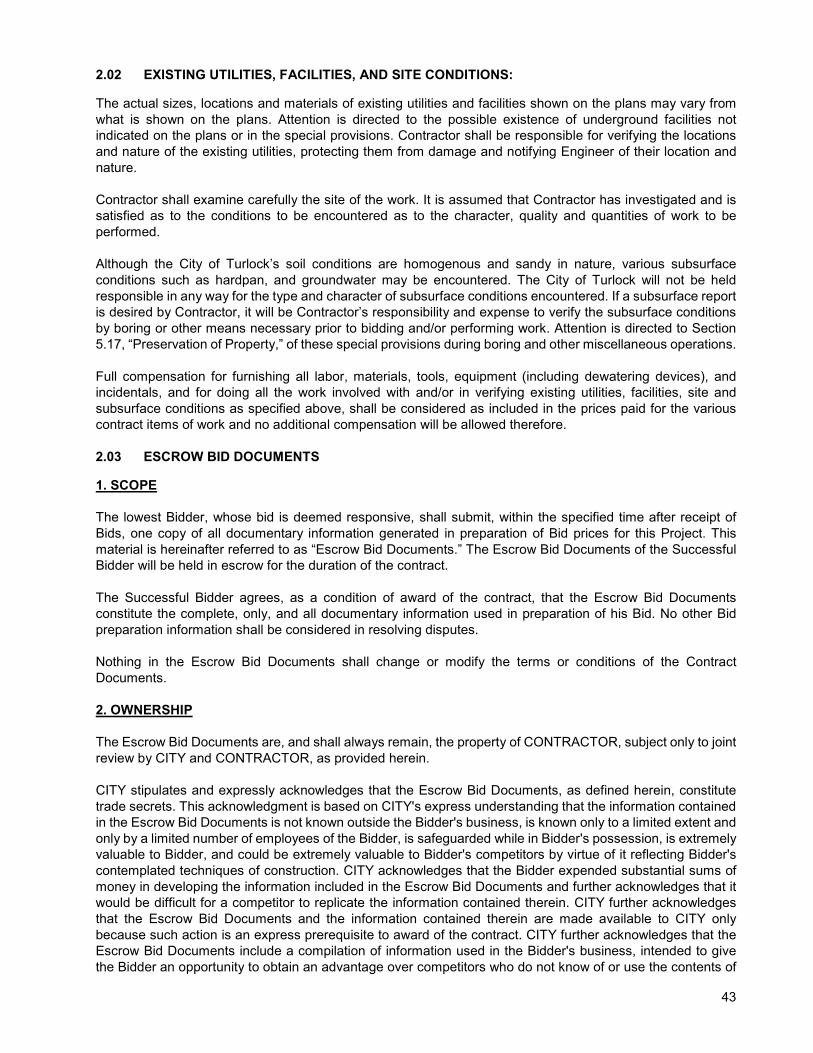
43
2.02 EXISTING UTILITIES, FACILITIES, AND SITE CONDITIONS:
The actual sizes, locations and materials of existing utilities and facilities shown on the plans may vary from what is shown on the plans. Attention is directed to the possible existence of underground facilities not indicated on the plans or in the special provisions. Contractor shall be responsible for verifying the locations and nature of the existing utilities, protecting them from damage and notifying Engineer of their location and nature. Contractor shall examine carefully the site of the work. It is assumed that Contractor has investigated and is satisfied as to the conditions to be encountered as to the character, quality and quantities of work to be performed. Although the City of Turlock’s soil conditions are homogenous and sandy in nature, various subsurface conditions such as hardpan, and groundwater may be encountered. The City of Turlock will not be held responsible in any way for the type and character of subsurface conditions encountered. If a subsurface report is desired by Contractor, it will be Contractor’s responsibility and expense to verify the subsurface conditions by boring or other means necessary prior to bidding and/or performing work. Attention is directed to Section 5.17, “Preservation of Property,” of these special provisions during boring and other miscellaneous operations. Full compensation for furnishing all labor, materials, tools, equipment (including dewatering devices), and incidentals, and for doing all the work involved with and/or in verifying existing utilities, facilities, site and subsurface conditions as specified above, shall be considered as included in the prices paid for the various contract items of work and no additional compensation will be allowed therefore. 2.03 ESCROW BID DOCUMENTS
1. SCOPE
The lowest Bidder, whose bid is deemed responsive, shall submit, within the specified time after receipt of Bids, one copy of all documentary information generated in preparation of Bid prices for this Project. This material is hereinafter referred to as “Escrow Bid Documents.” The Escrow Bid Documents of the Successful Bidder will be held in escrow for the duration of the contract. The Successful Bidder agrees, as a condition of award of the contract, that the Escrow Bid Documents constitute the complete, only, and all documentary information used in preparation of his Bid. No other Bid preparation information shall be considered in resolving disputes. Nothing in the Escrow Bid Documents shall change or modify the terms or conditions of the Contract Documents. 2. OWNERSHIP The Escrow Bid Documents are, and shall always remain, the property of CONTRACTOR, subject only to joint review by CITY and CONTRACTOR, as provided herein. CITY stipulates and expressly acknowledges that the Escrow Bid Documents, as defined herein, constitute trade secrets. This acknowledgment is based on CITY's express understanding that the information contained in the Escrow Bid Documents is not known outside the Bidder's business, is known only to a limited extent and only by a limited number of employees of the Bidder, is safeguarded while in Bidder's possession, is extremely valuable to Bidder, and could be extremely valuable to Bidder's competitors by virtue of it reflecting Bidder's contemplated techniques of construction. CITY acknowledges that the Bidder expended substantial sums of money in developing the information included in the Escrow Bid Documents and further acknowledges that it would be difficult for a competitor to replicate the information contained therein. CITY further acknowledges that the Escrow Bid Documents and the information contained therein are made available to CITY only because such action is an express prerequisite to award of the contract. CITY further acknowledges that the Escrow Bid Documents include a compilation of information used in the Bidder's business, intended to give the Bidder an opportunity to obtain an advantage over competitors who do not know of or use the contents of
44
the documentation. CITY agrees to safeguard the Escrow Bid Documents, and all information contained therein, against disclosure to the fullest extent permitted by law. 3. PROGRAM Escrow Bid Documents will be used to assist in the negotiation of price adjustments and Change Orders and in the settlement of disputes, claims, and other controversies. They will not be used for pre-award evaluation of CONTRACTOR's anticipated methods of construction or to assess CONTRACTOR's qualifications for performing the Work. 4. FORMAT AND CONTENTS Bidders may submit Escrow Bid Documents in their usual cost estimating format. It is not the intention of this section to cause the Bidder extra work during the preparation of the Bid, but to ensure that the Escrow Bid Documents will be adequate to enable complete understanding and proper interpretation for their intended use. The Escrow Bid Documents shall be in the language of the Specifications. The Escrow Bid Documents shall include all quantity takeoffs; crew; equipment; calculations of rates of production and progress; copies of quotations from equipment manufacturers, Subcontractors, and Suppliers; and memoranda, narratives, consultants' reports, add/deduct sheets, and all other information used by the Bidder to arrive at the prices contained in the Bidding Form. Estimated costs should be broken down into the Bidder's usual estimate categories, such as direct labor, repair labor, equipment operation, equipment ownership, expendable materials, permanent materials, and subcontract costs as appropriate. Plant and equipment and indirect costs should be detailed in the Bidder's usual format. CONTRACTOR's allocation of plant and equipment, indirect costs, contingencies, markup, and other items to each Bid item shall be included. Bidding Documents provided by the CITY should not be included in the Escrow Bid Documents unless needed to comply with the requirements of this section. 5. SUBMITTAL The Escrow Bid Documents shall be submitted in a sealed container within five working days, as requested in writing from the City. The container shall be clearly marked on the outside with the Bidder's name, date of submittal, project name, and the words "Escrow Bid Documents." The Escrow Bid Documents shall be accompanied with a certification signed by an individual authorized by the Bidder to execute the Bidding Form, stating that the material in the Escrow Documentation constitutes the complete, only, and all documentary information used in preparation of the Bid and that he has personally examined the contents of the Escrow Bid Documents container and has found that the documents in the container are complete. Prior to award, Escrow Bid Documents of the apparent Contractor will be unsealed, examined, organized, and inventoried by representatives of CITY, together with members of CONTRACTOR's staff who are knowledgeable in how the Bid was prepared. This examination is to ensure that the Escrow Bid Documents are authentic, legible, and complete. It will not include review or approval of proposed construction methods, estimating assumptions or interpretations of Contract Documents. This examination is subject to the condition that, as trade secrets, the Escrow Bid Documents are proprietary and confidential as described in Paragraph 2. Examination will not alter any condition(s) or term(s) of the contract. If all the documentation required in Part 4, "Format and Contents," has not been included in the original submittal, additional documentation shall be submitted, at CITY's discretion, prior to award of the contract. The detailed breakdown of estimated costs shall be reconciled and revised, if appropriate, by agreement between CONTRACTOR and CITY before making the award. If the contract is not awarded to the apparent Successful Bidder, the Escrow Bid Documents of the Bidder next to be considered for award shall be processed as described above.
45
Timely submission of complete Escrow Bid Documents is an essential element of the Bidder's responsibility and a prerequisite to contract award. Failure to provide the necessary Escrow Bid Documents will be sufficient cause for CITY to reject the Bid. If the Bidder's proposal is based on subcontracting any part of the Work, each Subcontractor whose total subcontract price exceeds 5 percent of the total Contract Price proposed by the Bidder shall provide separate Escrow Bid Documents to be included with those of the Bidder. These documents will be opened and examined in the same manner and at the same time as the examination described above for the apparent Successful Bidder. If CONTRACTOR subcontracts any portion of the Work after award, CITY retains the right to require CONTRACTOR to submit Escrow Bid Documents from the Subcontractor before the subcontract is approved. Escrow Bid Documents submitted by unsuccessful Bidders will be returned unopened, unless opened as provided above, as soon as they are no longer needed by CITY and no later than immediately following award of the contract. 6. STORAGE The Escrow Bid Documents of the Contractor will be placed in escrow prior to award of the contract, for the life of the contract, in a mutually agreeable institution. The cost of storage will be paid by CITY. 7. EXAMINATION AFTER AWARD OF CONTRACT The Escrow Bid Documents shall be examined by both CITY and CONTRACTOR, at any time deemed necessary after award of the contract by either CITY or CONTRACTOR, to assist in the negotiation of price adjustments and Change Orders, or the settlement of disputes. Examination of the Escrow Bid Documents after award of the contract is subject to the following conditions:
A. As trade secrets, the Escrow Bid Documents are proprietary and confidential as described in Paragraph 2.
B. CITY and CONTRACTOR shall each designate, in writing to the other party and a minimum of 10 days prior to examination, representatives who are authorized to examine the Escrow Bid Documents. No other person shall have access to the Escrow Bid Documents.
C. Access to the Escrow Bid Documents will take place only in the presence of duly designated representatives of both CITY and CONTRACTOR.
8. FINAL DISPOSITION The Escrow Bid Documents will be returned to CONTRACTOR at such time as the contract has been completed and final settlement has been achieved.
SECTION 3 - AWARD AND EXECUTION OF CONTRACT 3.01 GENERAL:
The Contractor’s attention is directed to the provisions in the Contract for the requirements and conditions concerning award and execution of contract. The contract shall be executed by the successful bidder and shall be returned, together with the contract bonds and insurance, to the City so that it is received within 10 working days after the bidder has received the contract for execution. Failure to do so shall be just cause for forfeiture of the proposal guaranty. The executed contract documents shall be delivered to the following address:
46
Attention: Tania Hernandez City of Turlock, Engineering Division 156 S Broadway, Suite 150 Turlock, CA 95380
3.02 BID PROTEST:
Bid protests are due in writing by the seventh calendar day after the bid opening and are to be delivered to the following address:
Nathan Bray, PE 156 S Broadway Suite 150 Turlock, CA 95380
Bid protest must be submitted with a non-refundable fee of $250.00 to review and respond to the repost. The Low Bidder shall respond to the bid protest upon notification by the Engineer. The award of the contract, if it be awarded, will be to the lowest responsible bidder whose bid complies with all the requirements prescribed.
SECTION 4 - BEGINNING OF WORK, TIME OF COMPLETION AND DELAY DAMAGES
Attention is directed to Section 5 “Time for Performance” of the Agreement. At no time shall construction begin prior to the issuance of the Notice to Proceed. Any work performed prior to the Notice to Proceed shall be done at the Contractor’s own risk and payment will not be made therefor. The Contractor shall follow the sequence of construction and progress of work as specified in Section 5.18, “Order of Work,” of these Special Provisions. Should the Contractor choose to work on a Saturday, Sunday or Legal Holiday as defined in Section 5.11 “Working Hours,” of these Special Provisions, the Contractor shall reimburse the City of Turlock the actual cost of engineering, inspection, testing, superintendent, and/or other overhead expenses which are directly chargeable to the contract. Should such work be undertaken at the request of the City, reimbursement will not be required. Attention is directed to Section 5(d) “Delay Damages” of the Agreement. A pre-construction meeting will be held between Contractor and City prior to the beginning of construction. The exact time and place of this conference will be determined by City after award of the construction contract. City shall furnish to Contractor five hard copies of the Contract Documents and plans. Contractor may produce additional copies as needed at Contractor’s expense.
SECTION 5 - GENERAL 5.01 LABOR NONDISCRIMINATION:
Attention is directed to the following Notice that is required by Chapter 5 of Division 4 of Title 2, California Code of Regulations. NOTICE OF REQUIREMENT FOR NONDISCRIMINATION PROGRAM (GOV. CODE, SECTION 12990)

47
Your attention is called to the "Nondiscrimination Clause", set forth in Section 7 1.01A(4), "Labor Nondiscrimination," of the Caltrans Standard Specifications, which is applicable to all nonexempt state contracts and subcontracts, and to the "Standard California Nondiscrimination Construction Contract Specifications" set forth therein. The Specifications are applicable to all nonexempt state construction contracts and subcontracts of $5,000 or more. 5.02 PREVAILING WAGE:
Attention is directed to Section 7-1.02K "Labor Code," of the Caltrans Standard Specifications. Pursuant to Section 1773 of the Labor Code, the general prevailing wage rates in the county Stanislaus in which the work is to be done have been determined by the Director of the California Department of Industrial Relations. These wages are set forth in the General Prevailing Wage Rates for this project, available at 156 S. Broadway St, Turlock, CA 95380 and available from the California Department of Industrial Relations’ Internet web site at http://www.dir.ca.gov/DLSR/PWD 5.03 REMOVAL OF ASBESTOS AND HAZARDOUS SUBSTANCES:
When the presence of asbestos or hazardous substances are not shown on the plans or indicated in the specifications and the Contractor encounters materials which the Contractor reasonably believes to be asbestos or a hazardous substance as defined in Section 25914.1 of the Health and Safety Code, and the asbestos or hazardous substance has not been rendered harmless, the Contractor may continue work in unaffected areas reasonably believed to be safe. The Contractor shall immediately cease work in the affected area and report the condition to the Engineer in writing. in conformance with Section 25914.1 of the Health and Safety Code, removal of asbestos or hazardous substances including exploratory work to identify and determine the extent of the asbestos or hazardous substance will be performed by separate contract. If delay of work in the area delays the current controlling operation, the delay will be considered a right of way delay and the Contractor will be compensated for the delay in conformance with the provisions in Section 8 1.07, "Delays," of the Caltrans Standard Specifications. 5.04 SUBCONTRACTING:
No subcontract releases the Contractor from the contract or relieves the Contractor of their responsibility for a subcontractor's work. If the Contractor violates Pub Cont Code § 4100 et seq., the City may exercise the remedies provided under Pub Cont Code § 4110. The City may refer the violation to the Contractors State License Board as provided under Pub Cont Code § 4111. Each subcontract must comply with the contract. Each subcontractor must have an active and valid State contractor's license with a classification appropriate for the work to be performed (Bus & Prof Code, § 7000 et seq.). At the pre-construction meeting, prior to starting work, Contractor shall submit a complete listing of subcontractors and the value of the work each subcontractor will perform. This list shall contain all information identified on Exhibit 12-G of the Local Assistance Procedures Manuel. Before subcontracted work starts, submit a Subcontracting Request form. Do not use a debarred contractor; a current list of debarred contractors is available at the Department of Industrial Relations' Web site.

48
Upon request by the Engineer, immediately remove and not again use a subcontractor who fails to prosecute the work satisfactorily. 5.05 PROMPT PROGRESS PAYMENT TO SUBCONTRACTORS:
A prime contractor or subcontractor shall pay any subcontractor not later than 10 days of receipt of each progress payment in accordance with the provision in Section 7108.5 of the California Business and Professions Code concerning prompt payment to subcontractors. The 10 days is applicable unless a longer period is agreed to in writing. Any delay or postponement of payment over 30 days may take place only for good cause and with the agency’s prior written approval. Any violation of Section 7108.5 shall subject the violating contractor or subcontractor to the penalties, sanction and other remedies of that section. This requirement shall not be construed to limit or impair any contractual, administrative, or judicial remedies otherwise available to the contractor or subcontractor in the event of a dispute involving late payment or nonpayment by the prime contractor, deficient subcontract performance, or noncompliance by a subcontractor. 5.06 PROMPT PAYMENT OF FUNDS WITHHELD TO SUBCONTRACTORS:
The agency shall hold retainage from the prime contractor and shall make prompt and regular incremental acceptances of portions, as determined by the agency, of the contract work, and pay retainage to the prime contractor based on these acceptances. The prime contractor, or subcontractor, shall return all monies withheld in retention from a subcontractor within 30 days after receiving payment for work satisfactorily completed and accepted including incremental acceptances of portions of the contract work by the agency. Federal law (49CFR26.29) requires that any delay or postponement of payment over 30 days may take place only for good cause and with the agency’s prior written approval. Any violation of this provision shall subject the violating prime contractor or subcontractor to the penalties, sanctions and other remedies specified in Section 7108.5 of the Business and Professions Code. These requirements shall not be construed to limit or impair any contractual, administrative, or judicial remedies otherwise available to the prime contractor or subcontractor in the event of a dispute involving late payment or nonpayment by the prime contractor, deficient subcontract performance, or noncompliance by a subcontractor. 5.07 PAYMENTS:
Attention is directed to Section 8, “Compensation,” of the Agreement. At the end of each month the Contractor shall submit a proposed progress invoice. The invoice shall delineate each bid item, the amount of work performed for the invoice period (previous month) and the total amount of work performed to date. A sample invoice with all of the required items will be given to the Contractor at the pre-construction meeting. The Engineer will review the progress invoice and after any changes the Engineer makes, will issue an official invoice for the Contractor to sign. The Contractor shall sign the official invoice and return to the Engineer. After the Engineer receives the signed, official invoice, the progress payment will be processed. Retention in the amount of 5% of the progress payment amount shall be held from all progress payments. Retention will be released 35 days after the Notice of Completion has been filed, insofar as no stop notices were filed. 5.08 GUARANTY:
Attention is directed to Section 9-4, “Guaranty,” of the City of Turlock Standard Specifications. 5.09 PUBLIC SAFETY:
in addition to any other measures taken by Contractor pursuant to the provisions of the Standard Specifications and the General Conditions, Contractor shall install temporary precast concrete barrier rail between any lane carrying public traffic and any excavation, obstacle or storage area when the following conditions exist: Excavations: Any excavation, the near edge of which is 12 feet or less from the edge of the lane, except;

49
(a) Excavations covered with sheet steel or concrete covers of adequate thickness to prevent
accidental entry by traffic or the public. (b) Excavations less than one foot deep. (c) Trenches less than one foot wide for irrigation pipe or electrical conduit or excavations less than
one foot in diameter. (d) Excavations parallel to the lane for the purpose of pavement widening or reconstruction. (e) Excavations in side slopes where the slope is steeper than 4:1. (f) Excavations protected by existing barrier or railing.
At the end of each working day, if a difference of 0.50 feet exists between the elevation of the existing pavement and the elevation of any excavation within 2 feet of the traveled way, material shall be placed and compacted against the vertical cuts adjacent to the traveled way. During excavation operations, native material may be used for this purpose, however, once the placing of the structural section commences, structural material shall be used. The material shall be placed to the level of the elevation of the top of the existing pavement and tapered at a slope of 4:1 or flatter to the bottom of the excavation. Treated base shall not be used for the taper. Full compensation for placing the material on a 4:1 slope, regardless of the number of times it is required, and subsequent removing or reshaping of the material to the lines and grades shown on the plans shall be considered as included in the cost for other contract items of work and no additional compensation will be allowed therefore. Personal vehicles of Contractor's employees shall not be parked on the traveled way or shoulders, including any section closed to public traffic. Whenever vehicles or equipment are parked on the shoulder within 6 feet of a traffic lane, the shoulder area shall be closed with traffic cones or portable delineators placed on a taper in advance of the parked vehicles or equipment and along the edge of the pavement at 25 foot intervals to a point not less than 25 feet past the last vehicle or piece of equipment. A minimum of one paved traffic lane, not less than 12 feet wide, shall be open for use by public traffic in each direction of travel. The full width of the traveled way shall be open for use by public traffic on Saturdays, Sundays and designated legal holidays, after 4:00 p.m. on Fridays and the day preceding designated legal holidays and when construction operations are not actively in progress. 5.10 SOUND CONTROL REQUIREMENTS:
Sound control shall be in accordance with Section 7 1.01I, “Sound Control Requirements,” of the Caltrans Standard Specifications and these special provisions. The noise level from Contractor's operations, between the hours of 9:00 p.m. and 6:00 a.m., shall not exceed 86 dba at a distance of 50 feet. This requirement in no way relieves Contractor from responsibility for complying with local ordinances regulating noise level. Said noise level requirements shall apply to all equipment on the job or related to the job, including but not limited to trucks, transit mixers or transient equipment that may or may not be owned by Contractor. The use of loud sound signals shall be avoided in favor of light warnings except those required by safety law for the protection of personnel. Full compensation for conforming to the requirements of this section shall be considered as included in the prices paid for the various contract items of work involved and no additional compensation will be allowed therefore.

50
5.11 WORKING HOURS:
Contractor's working hours shall be between 7:00 a.m. and 5:00 p.m., Monday through Friday, excluding legal holidays. Contractor shall notify Engineer 48 hours prior to beginning work. Contractor shall not work outside the above-mentioned working hours without prior written consent of Engineer. Designated legal holidays are: January 1st, the third Monday in January, the third Monday in February, the last Monday in May, July 4th, the first Monday in September, November 11th, Thanksgiving Day, the day after Thanksgiving, and December 25th. When a designated legal holiday falls on a Sunday, the following Monday shall be a designated legal holiday. When a designated legal holiday falls on a Saturday, the preceding Friday shall be a designated legal holiday. 5.12 UNDERGROUND SERVICE ALERT REQUIREMENTS:
Contractor shall contact Underground Service Alert of Northern California at least 48 hours in advance of any construction activity, will or could damage or affect any underground utility or subsurface improvement, and obtain an inquiry identification number. Contractor shall notify Underground Service Alert in the event of change in the project limits or change in original work previously shown on the plans or indicated in the specifications. Contractor shall not commence construction prior to City Inspector receiving City's notice from USA North regarding this construction activity. 5.13 DUST CONTROL:
Dust Control shall conform to the provisions in Section 10, “Dust Control”, of the Standard Specifications and these special provisions. Full compensation for Dust Control will be considered as included in the various contract items of work requiring Dust Control, as determined by Engineer, and no separate payment will be made therefor. 5.14 WATERING:
Watering shall be in accordance with Section 17, “Watering,” of the Caltrans Standard Specifications. Full compensation for Watering will be considered as included in the various contract items of work requiring Watering, as determined by Engineer, and no separate payment will be made therefor. 5.16 PROGRESS SCHEDULE:
Contractor shall furnish City with a Critical Path Method progress schedule. The progress schedule shall show the construction activities extending for the duration of the working days. Any deviation from the outline must be approved by Engineer. Contractor shall not be allowed to start construction activities until the progress schedule is accepted by Engineer. Contractor shall furnish one copy of scheduling software for use by Engineer. Software shall be MS Project, SureTrak, or equal. Software shall remain with Engineer after completion of contract. 5.17 PRESERVATION OF PROPERTY:
The work performed in connection with various existing facilities shall be in accordance with Section 7-8, “Preservation of Property,” of the Standard Specifications and these special provisions. Due care shall be exercised to avoid injury or damage to existing improvements or facilities, utility facilities, adjacent property, and roadside trees, shrubs and other plants that are to remain in place.

51
Roadside trees, shrubs and other plants that are not to be removed and pole lines, fences, signs, markers and monuments, buildings and structures, conduits, pipelines under or above aground, sewer and water lines, sprinkler systems above or below ground, all roadway facilities, and any other improvements or facilities within or adjacent to the right-of-way shall be protected from injury or damage, and if ordered by Engineer, Contractor shall provide and install suitable safeguards, approved by Engineer, to protect such objects from injury or damage. If such objects are injured or damaged by reason of Contractor's operations they shall be replaced or restored at Contractor's expense. The facilities shall be replaced or restored to a condition as good or better as when Contractor entered upon the work, or as good as required by the specifications accompanying the contract, if any such objects are a part of the work being performed under the contract. Engineer may make or cause to be made such temporary repairs as necessary to restore to service any damaged facility. The cost of such repairs shall be borne by Contractor and may be deducted from any moneys due or to become due to Contractor under the contract. The fact that any underground facility is not shown upon the plans shall not relieve Contractor of his responsibility under Section 2.02, “Existing Utilities and Facilities”, of these provisions. It shall be Contractor's responsibility, pursuant thereto, to ascertain the location of such underground improvements or facilities that may be subject to damage by reason of his operations. Full compensation for furnishing all labor materials, tools, equipment, and incidentals, and for doing all the work involved in protecting or repairing property as specified above, shall be considered as included in the prices paid for the various contract items of work and no additional compensation will be allowed therefor. 5.18 ORDER OF WORK:
The project consists of several loosely connected elements. In general, the Contractor shall determine the schedule of construction for each element. However, impacts to the day-to-day operation of the wastewater collection system should be minimized and coordinated with the City. 5.19 AS-BUILTS:
Provide and maintain on the jobsite one complete set of prints of all drawings which form a part of the contract. Immediately after each portion of the work is installed, indicate all deviations from the original design shown in the drawings either by additional sketches or ink thereon. Upon completion of the job, deliver this record set to the Owner’s Representative. The Contractor shall identify all utilities that are located in the field. The NOC will not be issued until acceptable as-builts have been received by the Engineer. 5.20 SURVEYING:
See Section 015100 of the Technical Specifications. 5.21 TESTING:
Unless otherwise noted, City of Turlock will supply all acceptance testing. Coordination of said testing is the responsibility of Contractor through the project’s inspector. The Contractor shall provide at least 24 hours’ notice to the Engineer in advance of needing acceptance testing. If the Contractor request testing and the Contractor is not ready for the testing to occur, the Contractor shall be back charged the cover the cost of the testing firm. At sites chosen by the project inspector, City’s testing laboratory will conduct all tests. Contractor shall supply any necessary equipment and or labor required to obtain all samples for the completion of the testing process. City of Turlock shall compensate the testing laboratory for all initial tests. Secondary and all other follow-up tests required due to failure of initial testing shall be reimbursed to City of Turlock based on the following schedule:
Water sample test: $300.00 Per Test Compaction test: $100.00 Per Test

52
5.22 SUBMITTALS:
5.22.1. Shop Drawings
A. The use of contract drawing reproductions for shop drawings is subject to rejection.
B. Submit shop drawings in .pdf format compatible with Adobe Acrobat Version 9. Files 5 MB or less may be submitted to the Owner’s Representative via email. Submit files larger than 5 MB by means of an FTP server, USB flash drive, or as approved by Owner’s Representative. Pages shall be scanned at a resolution necessary for readability. Scans shall be in color where appropriate for clarity. Superfluous catalog pages shall be excluded from submittals. Clearly indicate the specification section and drawing number to which each shop drawing is referenced.
C. If the Contractor submits shop drawings of equipment by manufacturers other than those listed in the specifications, provide the following information with the submittal:
1. The name and address of at least three companies or agencies that are currently using the equipment.
2. The name and telephone number of at least one person at each of the above companies or agencies whom the Owner's Representative may contact.
3. A description of the equipment that was installed at the above locations. The description shall be in sufficient detail to allow the Owner's Representative to compare it with the equipment that is proposed to be installed in this project.
D. For materials originating outside of the United States for which tests are required, provide recertification and retesting by an independent domestic testing laboratory.
5.22.2. Submittal Requirements
A. Make submittals promptly in such sequence as to cause no delay in the work. Schedule submission a minimum of 30 calendar days before reviewed submittals will be needed.
B. Submittals shall contain:
1. The date of submission and the dates of any previous submissions.
2. The project title and number.
3. Contract identification.
4. The names of:
a. Contractor.
b. Supplier.
c. Manufacturer.
5. Identification of the product, with the specification section number.
6. Field dimensions, clearly identified as such.
7. Relationship to adjacent or critical features of the work or materials.
8. Identification of deviations from contract documents.
9. Identification of revisions on resubmittals.

53
10. A 5-inch by 5-inch blank space for stamps of the Owner’s Representative.
11. Contractor’s stamp, initialed or signed, shall certify Contractor’s review of submittal, verification of products, field measurements and field construction criteria, and coordination of the information within the submittal that the product meets the requirements of the work and of the contract documents.
5.22.3. Submittal Format
A. Each submittal shall have a transmittal form. A sample transmittal form is included at the end of this section. Every page in a submittal shall be numbered in sequence.
B. Where product data from a manufacturer is submitted, clearly mark which model is proposed, with all pertinent data, capacities, dimensions, clearances, diagrams, controls, connections, anchorage, and supports. Present a sufficient level of detail for assessment of compliance with the contract documents.
C. Each submittal shall be assigned a unique number. Submittals shall be numbered sequentially. The submittal numbers shall be clearly noted on the transmittal. Original submittals shall be assigned a numeric submittal number. Resubmittals shall bear an alphanumeric system which consists of the number assigned to the original submittal for that item followed by a letter of the alphabet to represent that it is a subsequent submittal of the original. For example, if Submittal 25 requires a resubmittal, the first resubmittal will bear the designation “25-A” and the second resubmittal will bear the designation “25-B” and so on.
D. Disorganized submittals that do not meet the requirements above will be returned without review.
5.22.4. Resubmittals
Resubmittal of submittals will be reviewed and returned in the same review period as for the original submittal. It is considered reasonable that the Contractor shall make a complete and acceptable submittal by the second submission of a submittal item. The Owner’s Representative reserves the right to withhold monies due to the Contractor to cover additional costs of any review beyond the second submittal.
5.23 CLAIMS AND DISPUTES:
See Section 9 of Agreement for claims and disputes. 5.24 PRESERVATION OF EXISTING MONUMENTS:
Preservation of existing monuments shall be Contractor’s responsibility. Contractor shall notify Engineer of all monuments that may/will be disturbed by construction operations. Engineer will tie off said monuments and provide Contractor a notice to proceed. Once Contractor is finished with its construction operations, Engineer will relocate the monuments. Contractor shall install a monument will with concrete collar at each location which shall conform to the provisions in Section 22-1 “Survey Monuments” and Drawing M-1 “Monument Detail,” of the Standard Specifications and these special provisions. Full compensation for furnishing all labor, materials, tools, equipment, and incidentals, and for doing all the work involved with protecting existing monuments as specified above, shall be considered as included in the prices paid for the various contract items of work and no additional compensation will be allowed therefore. 5.25 BUSINESS LICENSE:
Contractor shall obtain a City of Turlock business license prior to issuance of the Notice to Proceed. The cost of the business license is fifty cents per thousand dollars in revenue. Business Licenses are obtained through

54
the Finance Division at Turlock City Hall, 156 S. Broadway, Suite 114. Additional information can be found on the City’s website at: http://ci.Turlock.ca.us/doingbusinessinTurlock/businesslicenses/newbusinesslicense.asp Full compensation for obtaining a business license as specified above shall be considered as included in the prices paid for the various contract items of work and no additional compensation will be allowed therefore. 5.26 INTERNET BASED CONSTRUCTION MANAGEMENT SYSTEM:
General The Engineer and Contractor shall utilize Virtual Project Manager (http://www.virtual-pm.com/), herein after called VPM, for submission of all data and documents (unless specified otherwise in this Section) throughout the duration of the Contract. VPM is an electronic project management system accessible through the Internet used to create, share, and review construction management documentation. VPM is provided by the Engineer at no cost to the Contractor. VPM will be made available to all Contractors’ personnel, subcontractor personnel, suppliers, consultants, Engineer, and any of Engineer’s representatives or agents. The joint use of this system is to facilitate electronic exchange of information, automation of key processes, electronic notification of project activity, and overall management of contract documentation. VPM shall be the primary means of project information submission and management. The Engineer will establish the Contractor’s access to VPM by enabling access and assigning user profiles to Contractor personnel, including subcontractors and suppliers, as requested by Contractor. All authorized personnel shall have an individual user profile; no joint-use or shared user profiles will be allowed. Each user profile shall be assigned to a user group and have specific permission settings and privileges based on the user’s need within VPM. Entry of information exchanged and transferred between the Contractor and its subcontractors and suppliers on VPM shall be the responsibility of the Contractor. The Contractor shall use computer hardware and software that meets the requirements of the VPM system. As recommendations are modified by VPM, the Contractor will upgrade their system(s) to meet or exceed the recommendations. Upgrading of the Contractor's computer systems will not be justification for a cost or time modification to the Contract. The Contractor shall ensure its own connectivity to VPM through their internet service provider. The Contractor shall be responsible for the validity of the information they place in VPM, for the training of their personnel to understand and utilize VPM, as well as the provision and accessibility of adequate resources to connect with VPM. Accepted users shall be knowledgeable in the use of computers, including Internet browsers, email programs, and the Portable Document Format (PDF) document type. The Contractor shall utilize the existing forms in VPM to the maximum extent possible. If a form does not exist in VPM the Contractor must include their own form or a form provided by the Engineer as an attachment to a submittal, RFI, or other document within VPM. Note that only the following file types are accepted as attachments to documents within VPM: PDF files, Microsoft Word (DOC) files, Microsoft Excel (XLS) files, picture files (JPG, TIFF, BMP, JPEG, etc.). PDF documents will be created through electronic conversion prior to uploading, such as through a “print to file” feature or “save as pdf” feature, rather than optically scanned whenever possible. Contractor shall provide a list of key VPM personnel for the Engineer’s acceptance. The list shall include the following information: first name, last name, address, title, office phone number, cell phone number, and email address. The Engineer is responsible for adding and removing users from the system and establishing read, write, and approval permission levels. Company Documents This area is reserved for general documentation not related to a specific project. Only the Engineer shall post content in this area. Examples of content found in this area are: the City of Turlock Standard Specifications and Drawings, the 2010 Caltrans Standard Specifications, and the 2010 Caltrans Standard Plans. All files are in PDF format.
55
Project Summary The project summary tab provides an overall summary of the project. It includes the current weather, the working days remaining and a summary of work for the past week. The summary of work is generated from the City’s project inspector and the daily logs. This tab is for information only and the Contractor shall not take any action here. Task Manager The project schedule the Contractor submits is converted into a format that is uploaded by the Engineer into the task manager tab. The Contractor is responsible for providing schedule updates to the Engineer whenever the work progress in a manner different than the approved schedule. Change Order Manager The change order manager tab shall be used to track project change orders. Any potential change orders shall be tracked as a Request for Information (RFI) in the RFI tab. Once the Engineer agrees that a RFI will result in a contract change order, a new contract change order shall be created by the Engineer in the change order manager tab. The Engineer will finalize the contract change order through this tab. Once the change order is finalized, the Engineer will present the contract change order at a City Council meeting. After City Council approval the Engineer will make payment on the contract change order. Transmittals The transmittal tab shall be used to communicate general project information amongst all parties as well as used by the Contractor in the submission of certified payroll reports. The Engineer will upload the project-specific information including: bid documents, conformed plans, conformed specifications and the Notice to Proceed to the transmittal tab. The Contractor shall submit certified payroll reports on a weekly basis through the transmittal tab. Each week shall have a separate transmittal where all the certified payroll reports and statements of non-performance for each contractor shall be posted. Submittals All submittals shall be submitted through the submittal tab. The preferred document type is PDF. Before making submittals, the Contractor shall ensure that products and materials will be available in the quantities and in the time required by the Contract and the approved schedule of activities. Each submittal shall be legible and clearly identify, by highlighting, arrows or other defined and permanent mark, the products and materials proposed for use. All submittals shall be generated from the prime contractor and any submittals that are uploaded by subcontractors or suppliers will not be reviewed. Contractor shall carefully review all subcontractor and suppliers submittals before submitting it to the Engineer for review. If a submittal contains extraneous information, unmarked options or is otherwise incomplete, it will be rejected and the Contractor shall make corrections and upload the resubmittal. Any resubmittal shall be made to the same transmittal item in VPM. Submittals shall be processed by the Engineer within ten working days after upload to VPM. The Engineer will review submittals for general conformance with the Contract Documents and standards. Such review by the Engineer shall not relieve the Contractor of any responsibility for full compliance with the Contract Documents. Unless specifically authorized to do so by the Engineer, the Contractor shall not procure, manufacture, or fabricate any part of the contract work until submittals related to said contract work have been approved by the Engineer. Each submittal shall have a unique title that is comprised of the item followed by a comma and the section of the specifications that reference the item (e.g. Minor Concrete, Section 8.01). The submittal type shall either be project materials or project information. The submittal description shall be used to identify any pertinent information or list a description of the item being submitted. Certificates of compliance shall be submitted through the submittal tab. The submittal type shall be “certificate of compliance”.

56
The Contractor shall submit progress invoices on the last working day of the month through the transmittal tab (select “progress invoice” for the type). The Engineer will review the submitted content and if found acceptable the Engineer will upload an official invoice for the Contractor to sign. The Contractor shall sign in blue ink and upload the signed invoice to the same transmittal where the Engineer will then process for payment. RFIs The RFI tab shall be used to request information from the Contractor to the Engineer. The Contractor shall create a RFI upon recognition of any event or question of fact arising from the contract work. The RFI type for this submittal shall be “Request for Information.” The Engineer will also utilize the RFI tab in a similar manner when there is a question for the Contractor; this RFI type shall be “Response Required.” The Engineer will respond to a RFI submitted by the Contractor within five days. The Contractor shall proceed with the work unless otherwise ordered. Daily Logs The daily log tab is used by the City to document the activities of the work, any correspondence or direction given in the field, safety concerns and general comments about the project. The Contractor may view the contents of this tab for reference purposes. The information entered into the daily log tab is used to populate the project summary tab. WSWD The weekly statement of working days will be posted to the WSWD tab. VPM automatically generates the WSWD from the information entered into the daily log tab. The WSWD shows the working days and non-working days charged for the reporting week, any time adjustments, a work completion date with the remaining working days left in the contract and the controlling activities for the week. The Contractor will be allowed 15 days from the last working day of the weekly statement to protest in writing the correctness of the statement. The Contractor shall submit a transmittal stating what is being protested and the reasons for protest. The Engineer will respond to the protest. The Contractor may protest the Engineer’s response by submitting a claim in accordance with Section 5.23 “Claims and Disputes” of the special provisions.
SECTION 6 - DESCRIPTION OF WORK The work consists, in general, of construction of a Sanitary Sewer Lift Stations 9, 42 & 55 Upgrade 330 feet square (108.900 square feet in area) paved with asphalt, soil cement, subgrade improvements, and drainage. Additional work includes the provision of a concrete washdown area, Vactor dumping structure, recycled water distribution mains, electrical conduit, vaults and street light bases for future lighting and electrical distribution. The new facilities will be served by an improved access road, and surrounded by a perimeter reinforced concrete push wall.
SECTION 7 - CONSTRUCTION DETAILS
Compensation for all work specified to be performed under this contract and shown on the drawings will be made under payment items listed herein and shown on the Bid Schedule. The contract prices for the said payment items shall be full compensation for all of the costs connected therewith including all labor, materials, tools, equipment, and incidentals furnished and doing all the work involved in completing the items of work including final cleanup as specified herein. It is the intent of this contract that the sum of all prices listed in the Bid Schedule shall represent the total lump sum cost of all work shown on the drawings and specified herein. Where items of work are not specifically defined in the schedule or included in the bid items, including mobilization and demobilization, these items shall be included in those bid items which are most closely related to the required work.

57
Separate payment will not be made for any item which is not specifically set forth in the bid items contained in the Proposal. Therefore, the Contractor's entire compensation for doing all work in accordance with the Contract Documents shall be included in the prices stated in the Proposal.
SECTION 8 - BID ITEM DESCRIPTIONS
Compensation for all work specified to be performed under this contract and shown on the drawings will be made under payment items listed in Section 012000 Measurement and Payment and shown on the Bid Schedule. The contract prices for the said payment items shall be full compensation for all of the costs connected therewith including all labor, materials, tools, equipment, and incidentals furnished and doing all the work involved in completing the items of work including final cleanup as specified herein. It is the intent of this contract that the sum of all prices listed in the Bid Schedule shall represent the total lump sum cost of all work shown on the drawings and specified herein. Where items of work are not specifically defined in the schedule or included in the bid items, including mobilization and demobilization, these items shall be included in those bid items which are most closely related to the required work.
Separate payment will not be made for any item which is not specifically set forth in the bid items contained in the Proposal. Therefore, the Contractor’s entire compensation for doing all work in accordance with the Contract Documents shall be included in the prices stated in the Proposal.
Bid Item 1 - Mobilization and Demobilization This item is a lump-sum bid for preparatory work and operations including, but not limited to, those necessary for the movement of personnel, equipment, supplies, and incidentals to the project site; for obtaining permits, bonds, and insurance; and for all other work and operations which must be performed or costs incurred prior to beginning work on the various contract items on the project site. This bid item is limited to a maximum of $30,000. Mobilization payment shall be made at the time of the first monthly pay request and shall be limited to 80 percent of the bid amount. Demobilization and removal of all equipment, supplies, and incidentals at the conclusion of the work is also included and shall be paid in the amount of 20 percent of the bid amount at the last monthly pay request.
Bid Item 2 - Record Drawings and O&M Manuals This is a lump-sum bid item for all costs for furnishing record drawings and operations and maintenance manuals in accordance with Section 019310 of the Technical Specifications. Payment shall be made following acceptance of these documents by the Owner and Owner’s Representative.
Bid Item 3 - Lift Station 9 Demolition This is a lump-sum bid item for all costs for removal and offsite disposal of wet and dry well tops, buried pipe, valves, appurtenances and electrical equipment identified for demolition on the project plans and in accordance with the Technical Specifications. Disposal of demolished material shall be in accordance with all applicable state and federal laws and regulations.
Bid Item 4 - Lift Station 9 New Lift Station and Related Appurtenances This is a lump-sum bid item for all costs for furnishing and installing the new lift station, wet well, piping valves, valve boxes, new manholes, paving repair, concrete slabs, bypass pumping, traffic control, and appurtenances complete in place as shown on the project plans. This bid item also includes all supports and connections necessary for a function system.
Bid Item 5 - Lift Station 9 Electrical and Instrumentation This is a lump-sum bid item for all costs for furnishing and installing all electrical conduits, wires, enclosures, service switchboard, motor control center, automatic transfer switch, wiring devices, grounding system, testing, and start-up as shown on the plans and in accordance with the Technical Specifications to provide a complete and operational system. This item also includes all costs necessary to integrate system inputs and outputs to the Turlock RWQCF SCADA system.
Bid Item 6 - Lift Station 42 Demolition This is a lump-sum bid item for all costs for removal and offsite disposal of wet well, buried pipe, valves, appurtenances and electrical equipment identified for demolition on the project plans and in accordance with
58
the Technical Specifications. Disposal of demolished material shall be in accordance with all applicable state and federal laws and regulations.
Bid Item 7 - Lift Station 42 New Lift Station and Related Appurtenances This is a lump-sum bid item for all costs for furnishing and installing the new lift station, wet well, piping valves, valve boxes, manholes, connection to existing system, paving repair, concrete slabs, bypass pumping, traffic control, and appurtenances complete in place as shown on the project plans. This bid item also includes all supports and connections necessary for a function system.
Bid Item 8 - Lift Station 42 Electrical and Instrumentation This is a lump-sum bid item for all costs for furnishing and installing all electrical conduits, wires, enclosures, service switchboard, motor control center, automatic transfer switch, wiring devices, grounding system, testing, and start-up as shown on the plans and in accordance with the Technical Specifications to provide a complete and operational system. This item also includes all costs necessary to integrate system inputs and outputs to the Turlock RWQCF SCADA system.
Bid Item 9 - Lift Station 55 Demolition This is a lump-sum bid item for all costs for removal and offsite disposal of valve box, buried pipe, valves, LS lid, appurtenances and electrical equipment identified for demolition on the project plans and in accordance with the Technical Specifications. Disposal of demolished material shall be in accordance with all applicable state and federal laws and regulations.
Bid Item 10 - Lift Station 55 New Lift Station and Related Appurtenances This is a lump-sum bid item for all costs for furnishing and installing the new lift station pumps and equipment, piping valves, valve boxes, and appurtenances complete in place as shown on the project plans. This bid item also includes all supports and connections necessary for a function system.
Bid Item 11 - Lift Station 55 Electrical and Instrumentation This is a lump-sum bid item for all costs for furnishing and installing all electrical conduits, wires, enclosures, service switchboard, motor control center, automatic transfer switch, wiring devices, grounding system, testing, and start-up as shown on the plans and in accordance with the Technical Specifications to provide a complete and operational system. This item also includes all costs necessary to integrate system inputs and outputs to the Turlock RWQCF SCADA system.
Bid Item 12 - Miscellaneous Work for Three Lift Stations This is a lump-sum bid item for all costs for furnishing and installing all miscellaneous work including, but not limited to, bollards, fencing, construction surveying, construction lighting and electrical power, labor and equipment for obtaining construction water, cleanup, start-up and testing, project closeout, and all other work not included within previous bid items as shown on the plans and in accordance with the Technical Specifications to provide a complete and operational project.
59
TECHNICAL SPECIFICATIONS

60
This page intentionally left blank
COORDINATION OF WORK, PERMITS, AND REGULATIONS 011100-1 60591029 TO#9 - 8 Jan 2020
SECTION 011100 COORDINATION OF WORK, PERMITS, AND REGULATIONS
1.01 DESCRIPTION
This section generally describes the project and includes work sequence and schedule, Contractor’s use of premises, maintenance and operation of existing facilities, construction survey staking, permits, and regulations.
1.02 GENERAL NATURE OF WORK
The work involves construction of two new lift stations, and abandonment or repurposing of existing facilities. The rehabilitation of one lift station by replacing pumps, piping and valves. Installation and upgrading of electrical and control systems. Associated appurtenances, buried pipelines, and bypass pumping.
1.03 LOCATION OF PROJECT SITE
1. Lift Station 9: Adjacent to railroad, west of Geer Rd. northwest of storm water detention basin.
2. Lift Station 42: East Ave, east of N. Quincey Rd
3. Lift Station 55: E Hawkeye Ave, east of N Daubenberger Rd
1.04 WORK SEQUENCE AND SCHEDULE
Coordinate any disruption to the sewage collection system with the Owner and Owner’s Representative.
1.05 CONTRACTOR’S USE OF PREMISES
In accordance with encroachment permit
1.06 MAINTENANCE AND OPERATION OF EXISTING FACILITIES
Coordinate deliverables to minimize disruption to local residents.
1.07 CONSTRUCTION SURVEY STAKING
Contractors responsibility as required.
1.08 PERMITS
A. The Owner has or will have submitted a Notice of Intent to Discharge, along with appurtenant fee, under the Construction Activities Storm Water General Permit (99-08-DWQ). Under this permit the Contractor must prepare and submit Storm Water Pollution Prevention Plan.

COORDINATION OF WORK, PERMITS, AND REGULATIONS 011100-2 60591029 TO#9 - 8 Jan 2020
B. Obtain and pay the fees for the following permits:
Name or Type of Permit Name, Address,
Telephone Number of Permitting Agency
Encroachment Permit City of Turlock Engineering Division 156 S. Broadway, Suite 150 Turlock, CA 95380 (209) 668-5520 Fax (209) 668-5563
Dust Control Plan San Joaquin Valley Air Pollution Control District Northern Region Office 4800 Enterprise Way Modesto, CA 95356 (209) 557-6400
NPDES dewatering and discharge permit for discharging water for pressure and leakage testing
Regional Water Quality Board, Central Valley Region
1685 “E” Street, Fresno CA 93706-2007
(559) 445-5116
State Water Resources Control Board (SWRCB) – Construction Activities Storm Water General Permit (2009-0009-DWQ) (SWPPP)
State Water Resources Control Board Sacramento, CA (916) 341-5536
Contact the permitting agencies listed above for current fees associated with each permit.
C. The permits contain requirements that affect the cost of project work and some permanent permits require supplementary work permits and fees to execute construction. Comply with the permit requirements and obtain and pay the fees involved with the supplementary work permits.
END OF SECTION

MEASUREMENT AND PAYMENT 012000-1 60591029 TO#9 - 8 Jan 2020
SECTION 012000 MEASUREMENT AND PAYMENT
1.01 WORK LISTED IN THE SCHEDULE OF WORK ITEMS
A. Work under this contract will be paid on a unit price or lump-sum basis as outlined on the Bid Form for the quantity of work installed.
B. The unit prices and lump-sum prices include full compensation for furnishing the labor, materials, tools, and equipment and doing all the work involved to complete the work included in the contract documents.
C. The application for payment will be for a specific item based on the percentage completed or quantity installed. The percentage complete will be based on the value of the partially completed work relative to the value of the item when entirely completed and ready for service.
1.02 WORK NOT LISTED IN THE SCHEDULE OF WORK ITEMS
A. Items in the special provisions, general requirements, and specifications which are not listed in the schedule of work items of the Bid Form are, in general, applicable to more than one listed work item, and no separate work item is provided therefor. Include the cost of work not listed but necessary to complete the project designated in the contract documents in the various listed work items of the Bid Form.
B. The bids for the work are intended to establish a total cost for the work in its entirety. Should the Contractor feel that the cost for the work has not been established by specific items in the Bid Form, include the cost for that work in some related bid item so that the Proposal for the project reflects the total cost for completing the work in its entirety.
1.03 INSURANCE, PERMITS AND TRAFFIC CONTROL
Payment for all insurance, permits and traffic control required for the project will be made at the contract lump-sum bid price and shall be divided equally throughout the length of the contract.
END OF SECTION

MEASUREMENT AND PAYMENT 012000-2 60591029 TO#9 - 8 Jan 2020
THIS PAGE INTENTIONALLY LEFT BLANK

CPM CONSTRUCTION SCHEDULE REQUIREMENTS 013216-1 60591029 TO#9 - 8 Jan 2020
SECTION 013216 CPM CONSTRUCTION SCHEDULE REQUIREMENTS
1.01 GENERAL
A. This section covers the requirements for submittal of a critical path method (CPM) construction schedule and an associated schedule of values.
B. Development of the schedule, the cost loading of the schedule, monthly payment requisitions, and project status reporting requirements of the contract shall employ computerized CPM scheduling. The CPM schedule shall be cost loaded based on the schedule of values or unit bid prices or combination thereof.
1.02 CPM PROGRAM
Use PRIMAVERA (R) P-3 or 4, SURETRAK(R), or MS Project, or an equivalent computer software for the CPM schedule, as approved by the Owner’s Representative.
1.03 SUBMITTALS
A. Within three calendar days of the Notice to Proceed, submit a written statement of CPM capability, verifying that the Contractor has qualified in-house personnel capable of using the CPM technique or that the Contractor employs a qualified CPM consultant. The statement shall identify the individuals who will perform the CPM scheduling and provide those individuals’ detailed resumes. Capability shall be verified by detailed description of construction projects and references on which the individuals have successfully applied computerized CPM and shall include at least two projects of similar nature, scope, and value not less than one-half the total bid price of this project. The statement shall also provide the contact persons for the referenced projects with current telephone and address information.
B. Submit an initial schedule within five days of the date of Notice to Proceed. If revisions are required to this initially submitted schedule, resubmit a revised schedule within seven calendar days after the Contractor receives the returned copy.
C. Submit a copy of the schedule, clearly showing progress made and actual “S” curves, on a monthly basis along with the Application for Payment.
D. Schedule submittals to the Owner’s Representative shall include 3 hard copies and one electronic copy of a CPM-type construction schedule, generally as outlined in the Associated General Contractors publication The Use of CPM in Construction.
E. Submit a preliminary schedule of values for the major components of the work within three days of the Notice to Proceed.
F. Prepare and submit a detailed schedule of values to the Owner’s Representative within 30 days from the date of Notice to Proceed.
1.04 PROJECT INFORMATION
Each network diagram and report tabulation shall be prefaced with the following summary data:
A. Project name.
B. Contractor.
CPM CONSTRUCTION SCHEDULE REQUIREMENTS 013216-2 60591029 TO#9 - 8 Jan 2020
C. Type of tabulation (initial or updated).
D. Project duration.
E. Project contract completion date.
F. Projected completion date.
G. Variance analysis per activity.
1.05 GRAPHIC NETWORK DIAGRAM AND TABULATED SCHEDULES
A. The completed schedule shall include a graphic network and tabulated schedules with the graphic network displayed on a sheet with a minimum size of 11 inches by 17 inches and a maximum size of 24 inches by 36 inches36 inches by 60 inches. The graphic network shall be the precedence diagram method (PDM). It may be divided into two or more sheets, if necessary, provided that all sheets are properly referenced. Notation on each activity arrow shall include a brief work description and an estimate of the time duration of the work. Show a calendar along the full length of each sheet. Plot each activity so that the beginning and completion dates can be readily determined by comparison to the calendar scale. Show activities using symbols and/or color that clearly designate whether it is a critical path or noncritical activity. Noncritical path activities shall show estimated work time and free float time.
B. Float Time:
1. Definition: Unless otherwise provided herein, float as referenced in these documents is total float. Total float is the period of time measured by the number of working days each noncritical path activity may be delayed before it and its succeeding activities become part of the critical path. If a noncritical path activity is delayed beyond its float period, that activity then becomes part of the critical path and controls the end date of the project. Thus, the delay of the noncritical path activity beyond its float period will cause delay to the project itself.
2. Float Ownership: Neither the Owner nor the Contractor owns the float time. The project owns the float time. As such, liability for delay of the project completion date rests with the party actually causing delay to the project completion date. For example, if Party A uses some but not all of the float time and Party B later uses the remainder of the float time as well as additional time beyond the float time, Party B shall be liable for the costs associated with the time that represents a delay to the project’s completion date. Party A would not be responsible for any costs since it did not consume all of the float time and additional float time remained; therefore, the project’s completion date was unaffected.
C. Display time at the top of the schedule, reading left to right, with no greater than weekly divisions.
D. The schedule shall indicate dates for important activities including:
1. A logical succession of work from start to finish. This logical succession, when accepted, is the Contractor’s work plan and is only designated as early start to accommodate standard computerized systems.
2. Detailed definition of each activity.
3. A logical flow of work crews/equipment (crews are to be defined by labor category and labor hours; equipment by type and hours).

CPM CONSTRUCTION SCHEDULE REQUIREMENTS 013216-3 60591029 TO#9 - 8 Jan 2020
4. Shop drawing submittals and reviews.
5. Decisions.
6. Product procurement and delivery.
7. Witnessed factory or field testing.
8. Beginning and completion of each element of construction.
9. Critical coordination dates.
10. Submittal of record drawings and equipment manuals.
11. Cleanup, final inspection, etc.
12. Any project milestones or phases of work that affect important dates, such as other parallel contracts.
E. Submit:
1. Activity sort by early start, organized by related elements.
2. Activity sort by float, organized by related elements.
3. Activity sort by predecessor/successor.
4. Narrative description of the logic and reasoning of the schedule.
5. Resource allocation by activity.
6. List of cost-loaded activities that identifies specific cost amount for each activity in the CPM schedule.
F. Show constraints between interrelated activities.
G. The initial schedule shall include the following minimum data for each activity:
1. Activity numbers.
2. Estimated duration.
3. Activity description.
4. Early start date (calendar dated).
5. Early finish date (calendar dated).
6. Status (whether critical).
7. Float.
8. Cost of activity.

CPM CONSTRUCTION SCHEDULE REQUIREMENTS 013216-4 60591029 TO#9 - 8 Jan 2020
9. Other resources including equipment hours by type, labor by craft or crew, and materials by units.
H. Where float time exists in activities, show the activities with early start/early finish times.
I. The schedule shall include a title block with the project title, the Contractor’s business name, the date of submittal or revision, and the signature of the Contractor’s authorized representative attesting to his review and accuracy of the submittal.
J. The duration indicated for each activity shall be in calendar days and shall represent the single best time considering the scope of the work and resources planned for the activity including time for inclement weather. Except for certain nonlabor activities, such as curing concrete or delivering materials, activity durations shall not exceed 14days, be less than one day, or exceed $50,000 in value unless otherwise accepted by the Owner’s Representative.
1.06 CONSTRUCTION SCHEDULE PROGRESS
If the Contractor’s progress has fallen behind the accepted construction schedule, the Contractor shall take such steps as may be required, including increasing the number of personnel, shifts, overtime operations, days of work, and amount of construction equipment until such time as the work is back on schedule. Increased costs of any accelerated work program shall be paid for by the Contractor. Submit such recovery schedule within 10 days upon written request by Owner’s Representative.
1.07 ACCEPTANCE
A. The finalized schedule will be acceptable to the Owner’s Representative when it provides an orderly progression of the Work to completion in accordance with the contract requirements, adequately defines the Contractor’s work plan, provides a workable arrangement for processing the submittals in accordance with the project specification requirements, and properly allocates resources (labor, equipment, and costs) to each activity (free of unbalances in resources). When the network diagram and tabulated schedule have been accepted, submit to six copies of the time-scaled network diagram; three six copies of a computerized, tabulated schedule in which the activities have been sequenced by activity numbers; and three copies of all reports required by this specification.
B. Also submit a CD that contain the schedule submittal information. The disk shall contain data compatible with the specified CPM program to generate network diagrams and schedule reports identical to the hard copies submitted.
C. Review of the Contractor’s project schedule is for conformance to the requirements of the contract documents only. Review by the Owner’s Representative of the Contractor’s project schedule does not relieve the Contractor of any of its responsibility whatsoever for the accuracy or feasibility of the project schedule, or of the Contractor’s ability to meet the interim milestone date(s) and the contract completion date, nor does such review and acceptance imply or expressly warrant, acknowledge, or admit the reasonableness of the logic, durations, labor, or equipment loading of the Contractor’s project schedule.
1.08 REVISIONS OR UPDATES TO CONSTRUCTION SCHEDULE
A. Submit a revised or updated construction schedule by the third day of each month. The data date shall be the 25th of the preceding month. Revise or update the schedule upon the occurrence of any of the following:

CPM CONSTRUCTION SCHEDULE REQUIREMENTS 013216-5 60591029 TO#9 - 8 Jan 2020
1. When delay in completion of any activity or group of activities indicates an overrun of the contract time or control point requirement by 10 working days or 10% of the remaining duration, whichever is less.
2. Delays in submittals, deliveries, or work stoppage are encountered which make replanning or rescheduling of the work necessary.
3. The schedule does not represent the actual prosecution and progress of the project as being performed in the field and progress for any activity is five working days behind the current schedule.
4. The Contractor will be performing work at an earlier date than is shown on the schedule and the work will require additional inspection and/or testing personnel.
B. In the event of any change to the contract, submit a time analysis of the effect on the critical path. If the Contractor maintains there is no impact, submit a statement to that effect.
C. The cost of revisions to the construction schedule resulting from Owner-initiated contract changes shall be included in the cost for the change in the work and shall be paid as part of the total cost of the change through the contract allowable percentages for changed work.
D. The cost of revisions to the construction schedule not resulting from authorized changes in the work shall be the responsibility of the Contractor.
E. Submittal of the updated construction shall be a condition for approval of the progress payment.
END OF SECTION

CPM CONSTRUCTION SCHEDULE REQUIREMENTS 013216-6 60591029 TO#9 - 8 Jan 2020
THIS PAGE INTENTIONALLY LEFT BLANK
PRECONSTRUCTION DIGITAL AUDIO-VIDEO DOCUMENTATION 013233-1 60591029 TO#9 - 8 Jan 2020
SECTION 013233 PRECONSTRUCTION DIGITAL AUDIO-VIDEO DOCUMENTATION
PART 1 - GENERAL
1.01 DESCRIPTION
This section includes materials and performance for preconstruction digital audio-video documentation and generally defines Contractor’s responsibilities, unless otherwise stated, for the following:
A. Equipment.
B. Submittals.
C. Technique.
D. Quality assurance.
1.02 VIDEO AND AUDIO QUALITY
A. Documentation shall be performed by a responsible commercial firm skilled and regularly engaged in the preparation of preconstruction color audio-video DVD documentation acceptable to the Owner.
B. Completed documentation shall reproduce bright, sharp pictures with accurate colors and shall be free from distortion or any other significant picture imperfection. The audio portion of the recording shall reproduce the commentary of the camera operator with proper volume, clarity, and be free of distortion.
C. The Owner’s Representative will accompany the commercial firm in performing the audio-video documentation. The accompanying personnel may direct the commercial firm to record certain features observed. Notify the Owner’s Representative seven days in advance so that the accompanying personnel can be scheduled.
D. Construction shall not proceed until the Owner and Owner’s Representative have reviewed the documentation and notified the Contractor of its acceptability. It is anticipated that such review will be completed within 10 days after submittal.
1.03 MEASUREMENT AND PAYMENT
No separate payment item is provided for this work. The cost of performing this work shall be incorporated into the bid item for mobilization.
PART 2 - MATERIALS
2.01 RECORDING EQUIPMENT
Utilize a high-resolution digital video camera with extended still frame capability.
2.02 RECORDING MEDIA
Utilize new, color DVD having:

PRECONSTRUCTION DIGITAL AUDIO-VIDEO DOCUMENTATION 013233-2 60591029 TO#9 - 8 Jan 2020
A. High resolution.
B. Extended still frame capability.
C. American TV Standard DVD playback capability.
PART 3 - EXECUTION
3.01 COVERAGE
A. Record coverage of surface features located in the construction’s zone of influence including, but not limited to:
1. Roadways, driveways, sidewalks, bicycle paths, and railroads.
2. Buildings, walls, and retaining walls.
3. Ponds, culvert ends, and drainage structures.
4. Landscaping, trees, shrubbery, fences, and irrigation heads.
B. Record the individual features of each item with particular attention being focused upon the existence of any existing faults, fractures, or defects.
C. Control pan rate, rate of travel, camera height, and zoom rate to maintain a steady clear view.
D. Limit recorded coverage to one side of any street at any one time.
E. Create a single, continuous, unedited recording which begins and ends within each portion of a particular construction area. The recording shall proceed in the direction of ascending baseline stationing.
3.02 AUDIO CONTENT
A. Simultaneously record audio content during videotaping.
B. Audio recording shall assist in viewer orientation and in any needed identification, clarification, or description of features being recorded.
C. Audio recording shall only consist of camera operator commentary.
3.03 INDEXING
A. Permanently label each DVD with a sequential number and the project name.
B. Index each DVD with a digital record of the time and date of the recording which is continuously displayed as the DVD is played.
C. Prepare a written log which describes the contents of each DVD including:
1. Names of streets or easements.
2. Coverage begin/end station and location.

PRECONSTRUCTION DIGITAL AUDIO-VIDEO DOCUMENTATION 013233-3 60591029 TO#9 - 8 Jan 2020
3. Recording date.
3.04 CONDITIONS
A. Record coverage during dry, clear weather and during daylight hours only.
B. Record coverage when the area is free of debris or obstructions.
C. Record coverage no more than 21 days prior to mobilization at the site.
END OF SECTION

PRECONSTRUCTION DIGITAL AUDIO-VIDEO DOCUMENTATION 013233-4 60591029 TO#9 - 8 Jan 2020
THIS PAGE INTENTIONALLY LEFT BLANK

CONSTRUCTION FACILITIES AND TEMPORARY CONTROLS 015100-1 60591029 TO#9 - 8 Jan 2020
SECTION 015100 CONSTRUCTION FACILITIES AND TEMPORARY CONTROLS
1.01 CONSTRUCTION WATER
A. Related Work Specified Elsewhere:
General Concrete Construction: 030500.
B. The use of potable water and location of the source shall be coordinated with the Municipal Services Department by calling (209) 668-3590. A backflow prevention device that is acceptable to the Municipal Services Department shall be provided by the Contractor.
C. Include the cost of construction water in the appropriate bid item to which it is appurtenant. The cost shall include full compensation for furnishing all labor, materials, tools, and equipment and doing all the work necessary to develop a sufficient water supply and furnishing the necessary equipment for applying the water as described in these specifications.
1.02 ELECTRICAL POWER--CONSTRUCTION PHASE
Provide for the purchase of power or provide portable power for the construction of the project where existing outlets are not available. Provide for the extension of utility lines to the point of usage. The cost of power shall be included in the appropriate bid items to which it is appurtenant and shall include full compensation for furnishing all labor, materials, tools, and equipment required to obtain and distribute power for construction purposes.
1.03 DUST CONTROL
Perform dust control operations to prevent construction operations from producing dust in amounts harmful to persons or causing a nuisance to persons living nearby or occupying buildings in the vicinity of the work. Use water or dust preventative to control dust.
1.04 FIRE DANGER
Minimize fire danger in the vicinity of and adjacent to the construction site. Provide labor and equipment to protect the surrounding private property from fire damage resulting from construction operations.
1.05 TRAFFIC REGULATION
See Section 011100, City of Turlock Encroachment Permit, and Section 15526.
1.06 ACCESS ROADS AND PARKING AREAS
A. Obtain access to project site through the existing gate on S. Walnut Road. Keep access roads clear at all times so that the Owner’s vehicles have access to the operational areas of the RWQCF.
B. The Contractor and his employees will not be permitted to park their vehicles in the Owner's parking lot.
END OF SECTION

CONSTRUCTION FACILITIES AND TEMPORARY CONTROLS 015100-2 60591029 TO#9 - 8 Jan 2020
THIS PAGE INTENTIONALLY LEFT BLANK

TRAFFIC REGULATION 015526-1 60591029 TO#9 - 8 Jan 2020
SECTION 015526 TRAFFIC REGULATION
1.01 DESCRIPTION
This section describes procedures for traffic regulation and temporary steel plate bridging during construction in public streets and highways.
1.02 STANDARD SPECIFICATIONS
Wherever reference is made to the State Specifications and Plans, such reference shall mean the State of California, Business, Transportation, and Housing Agency, Department of Transportation latest edition.
1.03 SUBMITTALS
The traffic control plan not less than 14 working days prior to start of construction operations, an alternate plan, prepared, signed, and sealed by a California licensed civil or traffic engineer to the for approval. Preparation of any additional traffic control plans or detail that may be required by the City of Turlock during the course of the work shall be the Contractor's responsibility. No work shall begin involving or requiring alternate traffic control until a traffic control plan is approved by the City.
1.04 GENERAL
A. Provide safe and continuous passage for pedestrian and vehicular traffic at all times.
B. Control traffic at those locations indicated and in conformance with the approved traffic control plans and specifications.
C. Furnish, construct, maintain, and remove detours, road closures, traffic signal equipment, lights, signs, barricades, fences, K-rail, flares, solar-powered flashing arrow signs, miscellaneous traffic devices, flagmen, drainage facilities, paving, and such other items and services as are necessary to adequately safeguard the public from hazard and inconvenience. All such work shall comply with the ordinances, directives, and regulations of authorities with jurisdiction over the public roads in which the construction takes place and over which detoured traffic is routed by the Contractor. After devices have been installed, maintain and keep them in good repair and working order until no longer required. Replace such devices that are lost or damaged, to such an extent as to require replacement, regardless of the cause of such loss or damage.
D. Prior to the start of construction operations, notify the police and fire department in whose jurisdiction the project lies, giving the expected starting date, completion date, and the names and telephone numbers of two responsible persons who may be contacted at any hour in the event of a condition requiring immediate emergency service to remove, install, relocate, and maintain warning devices. In the event these persons do not promptly respond or the authority deems it necessary to call out other forces to accomplish emergency service, the Contractor will be held responsible for the cost of such emergency service.
E. Provide a minimum of 48 hours' notice to the City of Turlock for any work which may affect signal loops, equipment, or devices. In the event that any underground utilities, traffic devices, pipes, or conduits are damaged and require emergency repair by the City of Turlock, all costs incurred by the City in making such repairs, plus 15% for administration costs, shall be paid by the Contractor.

TRAFFIC REGULATION 015526-2 60591029 TO#9 - 8 Jan 2020
F. Post temporary "No Parking - Tow Away" signs 48 hours prior to work in areas where parking is normally permitted. The City of Turlock Police Department shall be notified 48 hours prior to the posting of any temporary parking restrictions along the pipeline route.
G. Coordinate the relocation of public bus and school bus routes, bus stops, and trash collection services with the agencies listed on the plans in advance of construction activity.
H. Notify each postal address at least two working days prior to restricting parking along the project route via first class United States mail of the nature and duration of the parking restriction.
1.05 TRAFFIC CONTROL DEVICES AND SIGNS
A. Traffic control devices and temporary striping shall conform to the latest 2009 edition of the Manual of Uniform Traffic Control Devices (MUTCD. Construction signs shall conform to the latest edition of the FHA publication “Standard Highway Signs”
B. The placement of construction signing, striping, barricades, and other traffic control devices used for handling traffic and public convenience shall conform to the MUTCD.
C. Signs shall be reflectorized when they are used during hours of darkness. Cones and portable delineators used for night lane closures shall have reflective sleeves. Equip barricades used in the diversion of traffic with flashers if in place during hours of darkness.
D. During the duration of a detour, cover existing signs not in accordance with the traffic control plan. Relocate existing signs that are in force to provide visibility from all relocated traffic lanes.
1.06 TEMPORARY STEEL PLATE BRIDGING
A. When backfilling operations of an excavation in the traveled way, whether transverse or longitudinal, cannot be properly completed within a workday, provide steel plate bridging with a nonskid surface and shoring to preserve unobstructed traffic flow. In such cases, the following conditions shall apply:
1. Steel plates used for bridging shall extend a minimum of 12 inches beyond the edges of the trench.
2. Install steel plate bridging to operate with minimum noise.
3. Shore the trench to support the bridging and traffic loads.
4. Use temporary paving with cold asphalt concrete to feather the edges of the plates if plate installation by Method 2 is used.
5. Secure bridging against displacement by using adjustable cleats, shims, or other devices.
B. Install steel plate bridging and shoring using either Method 1 or 2:
1. Method 1 (For Speeds More Than 45 mph): The pavement shall be cold planed to a depth equal to the thickness of the plate and to a width and length equal to the dimensions of the plate.
2. Method 2 (For Speeds 45 mph or Less): Attach approach plate(s) and ending plate (if longitudinal placement) to the roadway by a minimum of two dowels predrilled into the corners of the plate and drilled 2 inches into the pavement. Butt subsequent plates to each other. Compact fine graded asphalt concrete to form ramps, maximum slope 8.5%

TRAFFIC REGULATION 015526-3 60591029 TO#9 - 8 Jan 2020
with a minimum 12-inch taper to cover all edges of the steel plates. When steel plates are removed, backfill the dowel holes in the pavement with either graded fines of asphalt concrete mix or concrete slurry.
C. Maintain the steel plates, shoring, and asphalt concrete ramps.
D. The following table shows the required thickness of steel plate bridging required for a given trench width:
Trench Width (feet)
Minimum Plate Thickness (inches)
1 1/2
1 1/2 3/4
2 7/8
3 1
4 1 1/4
E. For spans greater than 4 feet, prepare a structural design by a registered civil engineer and submit to the Owner's Representative for review.
F. Design steel plate bridging for HS20-44 truck loading. Maintain on the steel plate a nonskid surface having a minimum coefficient of friction equivalent to 0.35as determined by California Test Method No. 342. The Contractor may use standard steel plate with known coefficient of friction equal to or exceeding 0.35.
1.07 VEHICULAR TRAFFIC CONTROL
A. Accomplish construction in phases by detouring traffic from its normal patterns along the route in approximately intervals between major cross streets to form the construction zone.
B. Shoring members, beams, or other obstructions shall not be permitted within a 2-foot clearance between the edge of excavation and the edge of any traffic lane. At construction areas where an open trench exists and/or where traffic detour will be in existence during night hours, replace delineators with barricades or K-rail.
C. Accomplish construction in phases by detouring traffic from its normal patterns. Restore traffic to normal patterns in each phase before proceeding to the next phase.
D. Transition traffic lane transitions from permanent lanes to construction zone patterns in accordance with the requirements for the normal posted speed limit and as shown in the drawings.
1.08 PEDESTRIAN TRAFFIC CONTROL
A. Maintain and delineate a minimum of one 4-foot-wide pedestrian walkway along each public street at all times during construction. Maintain existing pedestrian accesses at intersections at all times. When existing crosswalks are blocked by construction activity, install signs directing pedestrian traffic to the nearest alternative crosswalk.
B. Erect a fence or provide other means of securement to preclude unauthorized entry to any excavation during all nonworking hours on a 24-hour basis including weekends and holidays. Said fence shall be a minimum of 7 feet high around the entire excavation, consisting of a minimum 9-gauge chain-link type fence fabric and shall be sturdy enough to prohibit toppling by
TRAFFIC REGULATION 015526-4 60591029 TO#9 - 8 Jan 2020
children or adults. There shall be no openings under the wire large enough for any child to crawl through. Lock any gates if no adult is in attendance. Place warning signs spaced on 50-foot centers on the outside of the fence with the statement "DEEP HOLE DANGER."
1.09 ACCESS TO ADJACENT PROPERTIES
A. Maintain reasonable access from public streets to adjacent properties at all times during construction. Prior to restricting normal access from public streets to adjacent properties, notify each property owner or responsible person, informing him of the nature of the access restriction, the approximate duration of the restriction, and the best alternate access route for that particular property.
1.10 PERMANENT TRAFFIC CONTROL DEVICES
A. Restriping of Streets: Permanent restriping shall be in accordance with the requirements of the agencies having jurisdiction. Place and remove temporary striping required for traffic control during construction by sandblasting. Temporary striping includes any striping required on any pavement replaced prior to the final surface course. Replace any damaged or obliterated raised pavement markers in accordance with the standards of the agency having jurisdiction.
END OF SECTION

STORM WATER RUNOFF CONTROL FOR SITES 015721-1 60591029 TO#9 - 8 Jan 2020
SECTION 015721 STORM WATER RUNOFF CONTROL FOR SITES
PART 1 - GENERAL
1.01 DESCRIPTION
A. This section describes work necessary by the Contractor to allow the Owner to comply with the California State Water Resources Control Board (SWRCB) Construction Activities Storm Water General Permit No. 2009-0009-DWQ (NPDES No. CAS000002) for discharges of storm water associated with construction activities for specific construction sites. Specifically, this includes the development and implementation of a Storm Water Pollution Prevention Plan (SWPPP). The work shall reflect the Contractor's experience, resources, and capabilities in determining and meeting the requirements of the General Permit.
B. Disposal of construction water from operations such as groundwater dewatering and water used for backfilling trenches for pipelines is not part of the work under this section. Refer to Sections 312300, 312316 and for permit requirements for those discharges.
1.02 RELATED WORK DESCRIBED ELSEWHERE
A. Coordination of Work and Permits: 011100.
B. Submittals: Special Provisions.
C. Construction Facilities and Temporary Controls: 015100.
D. Earthwork: 312300.
1.03 SUBMITTALS
A. Submit the SWPPP in electronic format following the procedure described for shop drawings in the Special Provisions.
B. Prepare and submit a hazardous materials business plan prior to equipment use on the site. The approved plan shall be followed for project construction. The plan shall include:
1. Specific bermed equipment maintenance and refueling areas.
2. Bermed and lined hazardous material storage areas on site that are covered during the rainy season.
3. Hazardous material spill cleanup equipment on site (e.g., sorbent pads, shovels, and bags to place contaminated soil in).
4. Workers trained in location and use of cleanup equipment.
1.04 SUMMARY OF PROCEDURE FOR SITES
A. Perform the risk determination per Section VIII of the General Permit No. 2009-0009-DWQ and the Division of Water Quality Fact Sheet Part II, “Rationale”; Section J, “Risk Determination”; paragraph 1, “Traditional Projects.”
B. For Risk Level 1 requirements, follow the requirements of Attachment C:

STORM WATER RUNOFF CONTROL FOR SITES 015721-2 60591029 TO#9 - 8 Jan 2020
1. Good site management housekeeping.
2. Nonstorm water management.
3. Erosion control.
4. Sediment controls.
5. Runoff and runoff controls.
6. Inspection, maintenance, and repair.
C. For Risk Level 2 requirements, follow the requirements of Attachment D:
1. Good site management housekeeping.
2. Nonstorm water management.
3. Erosion control.
4. Sediment controls.
5. Runoff and runoff controls.
6. Inspection, maintenance, and repair.
7. Rain event action plan.
D. For Risk Level 3 requirements, follow the requirements of Attachment E:
1. Good site management housekeeping.
2. Nonstorm water management.
3. Erosion control.
4. Sediment controls.
5. Runoff and runoff controls.
6. Inspection, maintenance, and repair.
7. Rain event action plan.
1.05 GENERAL CONSTRUCTION ACTIVITY STORM WATER PERMIT
A. Prepare and submit the SWPPP to the Owner for inclusion in the PRDs. For information regarding preparation of the SWPPP, see www.waterboards.ca.gov. The Owner will submit permit registration documents (PRDs) along with appurtenant fee, under the Construction Activities Storm Water General Permit (2009-0009-DWQ).
B. No work on the project site shall commence prior to the Owner submitting the PRDs. Allow no less than seven days after submitting the SWPPP to the Owner for receipt of notice from the Owner that the PRDs have been filed.

STORM WATER RUNOFF CONTROL FOR SITES 015721-3 60591029 TO#9 - 8 Jan 2020
C. The qualified SWPPP developer and qualified SWPPP practitioners responsible for creating, revising, overseeing, and implementing the SWPPP shall attend a State Water Board-sponsored or -approved qualified SWPPP developer and qualified SWPPP practitioner training course.
D. The SWPPP shall be appropriate for the type and complexity of the project and shall be developed and implemented to address project-specific conditions. The project SWPPP shall identify specific BMPs needed to address all possible generated pollutants.
E. Read and be familiar with the requirements contained in the General Permit necessary to develop an SWPPP. Attention is directed to the publication entitled Construction General Permit Fact Sheet (2009-0009-DWQ) which has been prepared by the state and should assist the Contractor in the development of the SWPPP. Copies of the Fact Sheet may be purchased by writing the SWRCB, Division of Water Quality, 1001 I Street, Sacramento, CA 95814, telephone 916-341-5455, www.waterbooks.ca.gov. In addition, see the California Storm Water Quality Association Storm Water Best Management Practice Handbook 2003, www.cabmphanbdbooks.com.
F. Compliance with the requirements contained in the General Permit may require the use of erosion and sedimentation control procedures outside the limits of immediate construction activity.
1.06 NOTICE OF INTENT (NOI)
The General Permit requires the Owner to file an NOI with the SWRCB. A copy of this NOI must be included in the SWPPP. The Owner will file the NOI with the SWRCB and provide a copy to the Contractor for inclusion in the SWPPP.
1.07 EROSION CONTROL PROTOCOL
A. Prior to start of any work, prepare an SWPPP for construction in compliance with the SWRCB’s Construction Activities Storm Water General Permit No. 2009-0009-DWQ. The General Permit became effective on July 1, 2010 and superseded order No. 99-008-DWQ. This plan shall be designed for no less than a 10-year, eight-hour duration storm event. Where possible, erosion control measures shall be installed prior to work beginning. Erosion and sediment control features shall be utilized during and immediately after grading to minimize impacts associated with erosion and off-site siltation.
B. Prior to construction-related discharges, construct energy dissipation measures at groundwater dewatering discharge points to prevent erosion.
C. Construct sedimentation basins for dewatering discharge points to prevent excess downstream sedimentation. These basins shall be constructed prior to dewatering and regularly maintained during construction, including after storm events, to remain in good working order.
D. Construct straw bale/filter fabric barriers, backed by wire fencing for strength, around spoil piles to contain sediment from runoff. Install these barriers prior to any stockpiling during the rainy season and immediately after stockpiling during the dry season and shall be regularly maintained, including during major rainfall events, until the stockpiles are completely removed.
E. After construction, place erosion control matting on disturbed slopes greater than 5:1 (20%), over seeding and mulching.
F. Construct straw bale or filter fabric barriers at the base of disturbed slopes, for a minimum of two months following slope completion (or until the end of the rainy season, whichever is longer), to reduce short-term erosion impacts prior to plant growth.

STORM WATER RUNOFF CONTROL FOR SITES 015721-4 60591029 TO#9 - 8 Jan 2020
G. Construct water bars, filter fabric fencing, or rice wattles at 50-foot (15-meter) intervals on slopes greater than 5:1 (20%).
1.08 HAZARDS AND HAZARDOUS MATERIALS
A. The project-specific SWPPP shall be prepared in compliance with the Statewide Construction Activities Storm Water General Permit No. 2009-0009-DWQ to prevent adverse impacts to nearby areas associated with construction-related incidental spills. This plan shall include a description of BMPs, spill prevention measures, spill containment equipment, and monitoring requirements.
B. The following pollution prevention measures shall be followed in association with pipeline construction:
1. If rain occurs during or within three days after concrete is placed for any structures, spread and secure plastic sheets or tarps over the concrete in such a manner to prevent rain from coming in contact with the concrete.
2. Wash out concrete trucks in a designated area where the material cannot run off into the stream or percolate into the groundwater. This area shall be specified on all applicable construction plans and be in place before any concrete is poured.
3. Upon entering the site and regularly thereafter, inspect and maintain equipment prior to working. Repair any leaks or hoses/fittings in poor condition before the equipment begins work.
1.09 MEASUREMENT AND PAYMENT
A. Costs to the Contractor for preparing and implementing the SWPPP shall be included as part of the lump-sum bid amount stated in the Proposal.
B. In addition, the Contractor shall be responsible for all of its costs associated with the implementation of the SWPPP and coordination with the Owner for the Owner's implementation of the MP, including the installation, maintenance, and removal of erosion control practices described in the SWPPP upon completion of the project or as requested by the Owner's Representative. These costs shall be included in the prices shown for the other related bid items.
PART 2 - MATERIALS
Not used.
PART 3 - EXECUTION
3.01 GENERAL
A. Develop and submit the SWPPP as required by the SWRCB Fact Sheet and the General Permit for acceptance by the Owner prior to commencement of construction activities. Refer to "Time for Completion" in Section 007300.
B. Comply with the conditions identified in the General Permit that apply to the work under this contract.
C. The Contractor’s personnel and subcontractors shall comply with the SWPPP.
STORM WATER RUNOFF CONTROL FOR SITES 015721-5 60591029 TO#9 - 8 Jan 2020
D. Keep the SWPPP on site during construction activity. Make available upon request of a representative of the RWQCB and/or other regulatory agency.
E. Amend the SWPPP whenever there is a change in construction or operations which may affect the discharge of significant quantities of pollutants to surface waters, groundwaters, or a municipal storm sewer system.
3.02 STORM WATER POLLUTION PREVENTION PLAN
The SWPPP shall provide a description of potential sources which are likely to add significant quantities of pollutants to storm water discharges or which may result in nonstorm water discharges from the construction site. A description of the items required to be included in the SWPPP is included in the General Permit.
3.03 IMPLEMENTATION FOR SITE PROJECTS
A. The SWPPP shall be implemented at the appropriate level to protect water quality at all times throughout the life of the project. The SWPPP shall remain on the site during construction activities, commencing with the initial mobilization and ending with the termination of coverage under the General Permit. The discharger shall make the SWPPP available at the construction site during working hours while construction is occurring and shall be made available upon request by a state or municipal inspector. When the original SWPPP is retained by a crew member in a construction vehicle and is not currently at the construction site, current copies of the BMPs and map/drawing shall be left with the field crew and the original SWPPP shall be made available via a request by radio or telephone. Once construction activities are complete, until stabilization is achieved, the SWPPP shall be available from the SWPPP contact listed in the PRDs.
B. Comply with Part II, Section I of the Division of Water Quality Fact Sheet regarding sampling, monitoring, reporting, and recordkeeping and Section XVI of the General Permit. Comply with the monitoring and reporting requirements for the previously established risk level.
3.04 DUTY TO COMPLY
A. Comply with the conditions identified in the General Permit and the SWPPP. Nonadherence with the conditions specified in the General Permit may constitute a violation of the Clean Water Act and the Porter-Cologne Water Quality Control Act and may be grounds for enforcement action by the RWQCB.
B. Take all reasonable steps to minimize or prevent any discharge in violation of the General Permit.
3.05 COMPLIANCE CERTIFICATION
A. An officer or other authorized representative of the Contractor shall certify in writing to the Owner annually and at the completion of construction, if it occurs before the next annual report, that its construction activity is and has been in compliance or has been modified to comply with the requirements of the General Permit and the SWPPP.

STORM WATER RUNOFF CONTROL FOR SITES 015721-6 60591029 TO#9 - 8 Jan 2020
B. If compliance with any of the General Permit and SWPPP requirements cannot be certified, notify the Owner immediately. The notification shall identify the type of noncompliance, describe the actions necessary to achieve compliance, and include a time schedule when compliance will be achieved. Submit each noncompliance notification to the Owner within 15 days of identification of the event.
END OF SECTION

CLEANING DURING CONSTRUCTION AND FINAL CLEANING 017410-1 60591029 TO#9 - 8 Jan 2020
SECTION 017410 CLEANING DURING CONSTRUCTION AND FINAL CLEANING
1.01 GENERAL
A. This section includes cleaning during construction and final cleaning on completion of the work.
B. At all times maintain areas covered by the contract and adjacent properties and public access roads free from accumulations of waste, debris, and rubbish caused by construction operations.
C. Conduct cleaning and disposal operations to comply with local ordinances and antipollution laws. Do not burn or bury rubbish or waste materials on project site. Do not dispose of volatile wastes, such as mineral spirits, oil, or paint thinner, in storm or sanitary drains. Do not dispose of wastes into streams or waterways.
D. Use only cleaning materials recommended by manufacturer of surface to be cleaned.
1.02 CLEANING DURING CONSTRUCTION
A. During execution of work, clean site, adjacent properties, and public access roads and dispose of waste materials, debris, and rubbish to assure that buildings, grounds, and public properties are maintained free from accumulations of waste materials and rubbish.
B. Wet down dry materials and rubbish to lay dust and prevent blowing dust.
C. Provide containers for collection and disposal of waste materials, debris, and rubbish.
D. Cover or wet excavated material leaving and arriving at the site to prevent blowing dust. Clean the public access roads to the site of any material falling from the haul trucks.
1.03 FINAL CLEANING
A. At the completion of work and immediately prior to final inspection, clean the entire project site as follows.
B. Clean, sweep, wash, and polish all work and equipment including finishes.
C. Remove grease, dust, dirt, stains, labels, fingerprints, and other foreign materials from sight-exposed interior and exterior finished surfaces; polish surfaces.
D. Repair, patch, and touch up marred surfaces to match adjacent surfaces.
E. Broom clean paved surfaces; rake clean landscaped areas.
F. Remove from the site temporary structures and materials, equipment, and appurtenances not required as a part of, or appurtenant to, the completed work.
END OF SECTION

CLEANING DURING CONSTRUCTION AND FINAL CLEANING 017410-2 60591029 TO#9 - 8 Jan 2020
THIS PAGE INTENTIONALLY LEFT BLANK

OPERATION AND MAINTENANCE MANUALS 019310-1 60591029 TO#9 - 8 Jan 2020
SECTION 019310 OPERATION AND MAINTENANCE MANUALS
1.01 GENERAL
Submit six copies of all manufacturer’s operation and maintenance manuals and data pertinent to equipment supplied for the project. Prepare and organize the material in three-ring binders with divider tabs and labels. Include a table of contents. Include a CD of all catalog data in pdf format and all drawings in both pdf and CADD formats. All pdf files shall be formatted to allow word search.
1.02 SUBMITTALS
A. Submittals shall include:
1. List of equipment furnished for project with name, address, and telephone number of each vendor.
2. List of serial numbers of equipment furnished.
3. A copy of shop drawings for mechanical, electrical, and instrument equipment in final form.
4. Manufacturer’s operation and maintenance instructions and parts lists.
5. Tabulation of motor nameplate horsepower, nameplate current, field-measured current, overload relay setting, and catalog number for polyphase motors.
6. List of fuses, lamps, seals, and other expendable equipment and devices. Specify size, type, and ordering description. List name, address, e-mail address, website address, fax number, and telephone number of vendor.
B. Provide manuals for each piece of equipment including individual components and subsystems of complete assemblies. Line out nonapplicable text and illustrations. The section of the manual on operation shall describe the functions and limitations of each component and its relationship to the system of which it is a part. Where several models, options, or styles are described, the manual shall identify the items actually provided.
C. Each manual shall contain the following:
1. Manufacturer’s identification, including order number, model, and serial number.
2. Blue line prints or reviewed shop drawings and diagrams of all systems, .
3. Certified equipment drawings or reviewed shop drawing data clearly marked for equipment furnished.
4. Complete operating and maintenance instructions for each and every item of equipment, setting forth in detail and step-by-step the procedure for starting, stopping, operating, and maintaining the entire system as installed. Include a schedule of recommended maintenance intervals.
5. Complete parts list of replaceable parts, their part numbers, and the name and address of their nearest vendor.
OPERATION AND MAINTENANCE MANUALS 019310-2 60591029 TO#9 - 8 Jan 2020
6. A complete valve tag list including the name and function of the pipe in which the valve is mounted.
7. Any special emergency operating instruction and a list of service organizations (including addresses and telephone numbers) capable of rendering emergency service to the various parts of the system.
8. Copy of manufacturer’s equipment guarantees and warranties.
D. Brochures shall be loose leaf with durable plastic or fiberboard covers. Each sheet shall be reinforced to prevent tearing from continued use, and each brochure shall have the following information clearly printed on its cover:
1. Project name, name of Owner, and address.
2. Name and address of Owner’s Representative.
3. Name and addresses of contractors and subcontractors and department to contact.
4. Telephone number of contractors, including night and emergency numbers.
5. Major equipment vendors’ names and telephone numbers.
E. Submit complete manuals at least four weeks before the date of the instructions required by the subsections on “Manufacturer’s Services” in the various specification sections.
F. Operation and maintenance manuals specified herein are in addition to any operation, maintenance, or installation instructions required by the Contractor to install, test, and start up equipment.
1.03 EQUIPMENT DATA SHEETS
Provide six sets of equipment data sheets, bound in three-ring binders, summarizing the equipment manufacturer’s maintenance instructions and recommendations. A blank data sheet and a sample data sheet are attached.

OPERATION AND MAINTENANCE MANUALS 019310-3 60591029 TO#9 - 8 Jan 2020
Preventive Maintenance and Operating Requirement Sheets
Preventive Maintenance Program Equipment Record Number
EQUIPMENT DESCRIPTION ELECTRICAL OR MECHANICAL DATA
Name:
Size:
Serial No.: Model:
Vendor:
Vendor Address:
Type:
Mfr.:
Vendor Rep: Voltage: Amps:
Phone: Phase: rpm:
Maintenance Work to be Done Frequency*
OPERATING REQUIREMENTS AND REFERENCE
*D - Daily; W - Weekly; B - Biweekly; M - Monthly; Q - Quarterly;
S - Semiannually; A - Annually.

OPERATION AND MAINTENANCE MANUALS 019310-4 60591029 TO#9 - 8 Jan 2020
SAMPLE
Preventive Maintenance and Operating Requirement Sheets
Preventive Maintenance Program Equipment Record Number
EQUIPMENT DESCRIPTION ELECTRICAL OR MECHANICAL DATA
Name: Influent Pump No. 1
Tag No.: P01-1
Size: 15 hp
Serial No.: 123456ABC
Vendor: ABC Pump Co.
Model: 140T Frame
Serial No. 987654ZY
Class F Insulation
W/Space Heater
Vendor Address: Type:
1111 Pump Circle
Newport Beach, CA 92663
Mfr.: DEF Motors, Inc.
Vendor Rep: XYZ Equipment, Inc. Voltage: 460 Amps: 20
Phone: 714/752-0505 Phase: 3 rpm: 1,800
Maintenance Work to be Done Frequency*
1. Operate all valves and check such things as a) bearing temperature, b) changes
in running sound, c) suction and discharge gauge readings, d) pump discharge
rate, and e) general condition of the drive equipment.
2. Check packing.
3. Checking pumping unit for any dust, dirt, or debris.
(Continued on attached sheet)
D
D
W
OPERATING REQUIREMENTS AND REFERENCE
For manufacturer’s instructions regarding installation, operation, maintenance, and trouble shooting of this
equipment, see Volume ____, Section ______.
*D - Daily; W - Weekly; B - Biweekly; M - Monthly; Q - Quarterly;
S - Semiannually; A - Annually.
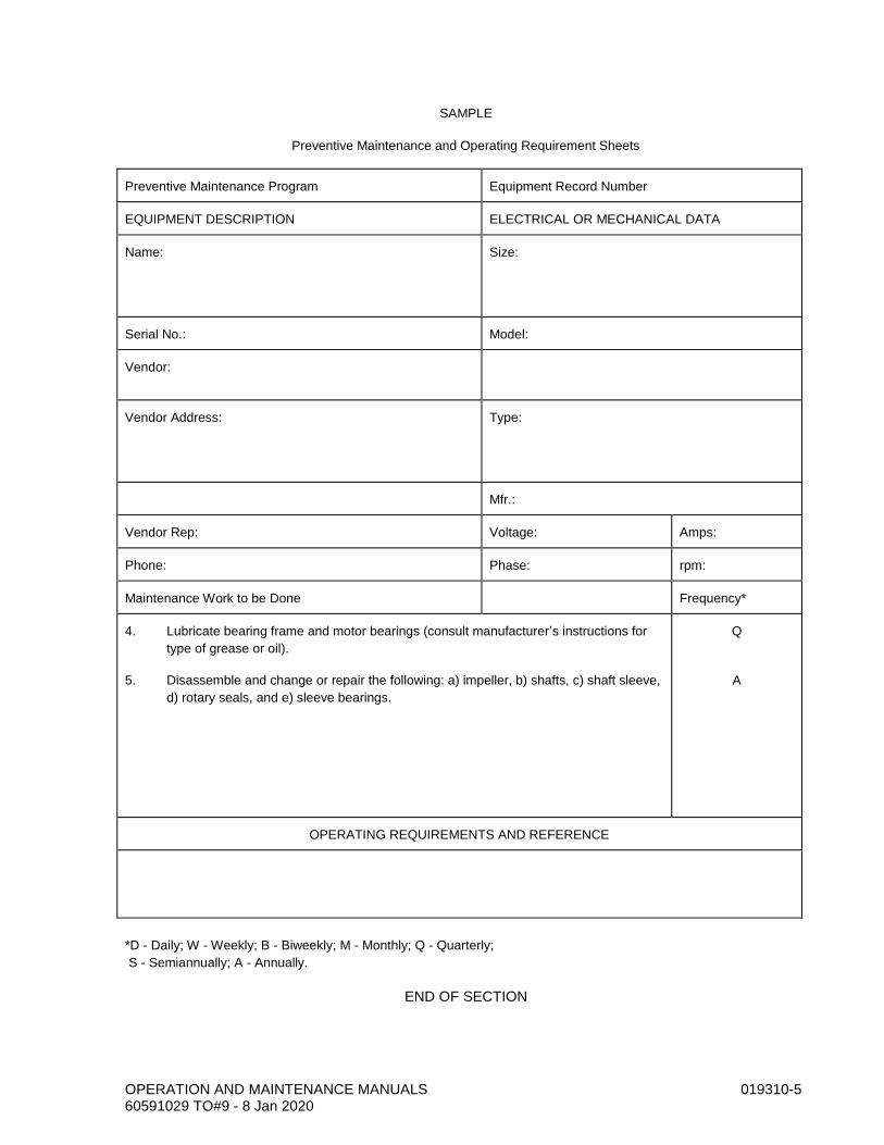
OPERATION AND MAINTENANCE MANUALS 019310-5 60591029 TO#9 - 8 Jan 2020
SAMPLE
Preventive Maintenance and Operating Requirement Sheets
Preventive Maintenance Program Equipment Record Number
EQUIPMENT DESCRIPTION ELECTRICAL OR MECHANICAL DATA
Name:
Size:
Serial No.: Model:
Vendor:
Vendor Address:
Type:
Mfr.:
Vendor Rep: Voltage: Amps:
Phone: Phase: rpm:
Maintenance Work to be Done Frequency*
4. Lubricate bearing frame and motor bearings (consult manufacturer’s instructions for
type of grease or oil).
5. Disassemble and change or repair the following: a) impeller, b) shafts, c) shaft sleeve,
d) rotary seals, and e) sleeve bearings.
Q
A
OPERATING REQUIREMENTS AND REFERENCE
*D - Daily; W - Weekly; B - Biweekly; M - Monthly; Q - Quarterly;
S - Semiannually; A - Annually.
END OF SECTION

OPERATION AND MAINTENANCE MANUALS 019310-6 60591029 TO#9 - 8 Jan 2020
THIS PAGE INTENTIONALLY LEFT BLANK
PROTECTING EXISTING UNDERGROUND UTILITIES 020120-1 60591029 TO#9 - 8 Jan 2020
SECTION 020120 PROTECTING EXISTING UNDERGROUND UTILITIES
PART 1 - GENERAL
1.01 DESCRIPTION
This section includes materials and procedures for protecting existing underground utilities.
1.02 RELATED WORK SPECIFIED ELSEWHERE
A. Connections to Existing Buried Pipelines: 020130.
B. Trenching, Backfilling, and Compacting: 312316.
C. Subsurface Utility Locating (Potholing): 023219.
PART 2 - MATERIALS
2.01 REPLACEMENT IN KIND
Except as indicated below or as specifically authorized by the Owner’s Representative, reconstruct utilities with new material of the same size, type, and quality as that removed.
2.02 VITRIFIED CLAY SEWER PIPE AND COUPLINGS
For sewer pipe 8 inches and less in diameter, replacement shall consist of plain-end pipe conforming to ASTM C700. Compression couplings shall conform to ASTM C594, band seal couplings or equal. Use at least two lengths of pipe in crossing the trench section.
PART 3 - EXECUTION
3.01 GENERAL
A. Replace in kind street improvements, such as curbs and gutters, barricades, traffic islands, signalization, fences, signs, etc., that are cut, removed, damaged, or otherwise disturbed by the construction.
B. Where utilities are parallel to or cross the construction but do not conflict with the permanent work to be constructed, follow the procedures given below. Notify the utility owner 48 hours in advance of the crossing construction and coordinate the construction schedule with the utility owner ’s requirements. For utility crossings not shown in the drawings, refer to the General Conditions and the instructions of the Owner’s Representative for guidance.
C. Determine the true location and depth of utilities and service connections which may be affected by or affect the work. Determine the type, material, and condition of these utilities. In order to provide sufficient lead-time to resolve unforeseen conflicts, order materials and take appropriate measures to ensure that there is no delay in work.
D. Expose utilities in advance of the pipeline construction.

PROTECTING EXISTING UNDERGROUND UTILITIES 020120-2 60591029 TO#9 - 8 Jan 2020
3.02 PROCEDURES
A. Protect in Place: Protect utilities in place, unless abandoned, and maintain the utility in service, unless otherwise specified in the drawings or in the specifications.
B. Cut and Plug Ends: Cut abandoned utility lines and plug the ends. Plug storm drains and sewers with an 8-inch wall of brick and mortar. Cap waterlines with a cast-iron cap or install a 3-foot-long concrete plug. Dispose of the cut pipe as unsuitable material.
C. Remove and Reconstruct: Where so indicated in the drawings or as required by the Owner’s Representative, remove the utility and, after passage, reconstruct it with new materials. Provide temporary service for the disconnected utility.
3.03 COMPACTION
A. Utilities Protected in Place: Backfill and compact under and around the utility so that no voids are left.
B. Utilities Reconstructed: Prior to replacement of the utility, backfill the trench and compact to an elevation 1 foot above the top of the ends of the utility. Excavate a cross trench of the proper width for the utility and lay, backfill, and compact.
C. Alternative Construction-Sand-Cement Slurry: Sand-cement slurry consisting of one sack (94 pounds) of portland cement per cubic yard of sand and sufficient moisture for workability may be substituted for other backfill materials to aid in reducing compaction difficulties. Submit specific methods and procedures for the review of the Owner’s Representative prior to construction.
3.04 SPECIAL CONSTRUCTION
A. Reinforced Concrete Beam: Where indicated in the drawings or as determined by the Owner’s Representative, support utilities by a reinforced concrete beam as shown on the utility support details in the drawings. The primary purpose of the beam is to prevent settlement of the utility line after construction. The Contractor is responsible for the protection of the utility during construction and shall incorporate the beam as part of the protection.
B. Concrete Support Wall: Where indicated in the drawings or as determined by the Owner’s Representative, support the utilities by a concrete support wall as shown on the utility support details in the drawings. The purpose of the concrete support wall is to prevent settlement of the utility line after construction. The Contractor is responsible for the protection of the utility during construction.
3.05 THRUST BLOCKS ON WATERLINES
A. The Contractor’s attention is called to thrust blocks for waterlines throughout the project whose thrust is in the direction of the new excavation and, therefore, may be affected by the construction. These waterlines are owned and operated by the Owner. Protect thrust blocks in place or shore to resist the thrust by a means approved by the Owner’s water division superintendent and reconstruct. If the thrust blocks are exposed or rendered to be ineffective in the opinion of the Owner’s Representative, reconstruct them to bear against firm unexcavated or backfill material.

PROTECTING EXISTING UNDERGROUND UTILITIES 020120-3 60591029 TO#9 - 8 Jan 2020
B. Provide firm support by backfilling that portion of the trench for a distance of 2 feet on each side of the thrust block to be reconstructed from the pipe bedding to the pavement subgrade, with either:
1. Sand-cement slurry (94 pounds of cement per cubic yard).
2. The native material compacted to a relative compaction of 95%.
C. Then excavate the backfill material for construction of the thrust block.
D. Test compaction of the backfill material before pouring any concrete thrust block. Use Class C concrete per Section 030500 for reconstruction.
3.06 ADJACENT PARALLEL UTILITIES
A. The Contractor’s attention is called to the following utilities: None were identified. Contractor shall perform his own investigation prior to installation of pipelines and facilities.
END OF SECTION

PROTECTING EXISTING UNDERGROUND UTILITIES 020120-4 60591029 TO#9 - 8 Jan 2020
THIS PAGE INTENTIONALLY LEFT BLANK

CONNECTIONS TO EXISTING BURIED PIPELINES 020130-1 60591029 TO#9 - 8 Jan 2020
SECTION 020130 CONNECTIONS TO EXISTING BURIED PIPELINES
PART 1 - GENERAL
1.01 DESCRIPTION
This section includes materials and installation of ductile-iron, steel and PVC (cast-iron outside diameter) pipeline line stopping and replacement of existing piping.
1.02 RELATED WORK SPECIFIED ELSEWHERE
A. Protecting Existing Underground Utilities: 020120.
B. Painting and Coating: 099000.
C. Cold-Applied Wax Tape Coating: 099752.
D. Polyethylene Sheet Encasement: 099754.
E. Fusion-Bonded Epoxy Linings and Coatings: 099761.
F. Manual, Check, and Process Valves: 400520.
1.03 SUBMITTALS
A. Submit shop drawings in accordance with the Special Provisions.
B. Submit manufacturer’s catalog data for tapping sleeves. Show coatings.
PART 2 - MATERIALS
2.01 LINE STOPPING FOR EXISTING FORCE MAIN
A. Before beginning line stop installation, the Contractor shall coordinate work with the City of Turlock Utilities Department.
B. The outside and inside diameters of the existing pipeline are required prior to ordering the tapping fitting and line stopper. Using the exposed portion of the pipeline, determine the outside diameter and inside diameter of the existing main for providing to the line stopping equipment manufacturer. Determine the pipe wall thickness by ultrasonic testing.
C. The line stop tapping fitting shall be a full encirclement split tee, Type 304 stainless steel, assembled with either a bolted or clamped connection. Bolts shall be steel, ASTM A325 heavy hex. Seal the line stop tapping fitting to the existing main with a nonasbestos synthetic rubber gasket. Construct the gasket from the following materials: Buna-N, Teflon, Kevlar aramid fiber, or acrylic fiber bound by nitrile. The split tee outlet flange shall be Class 125 per AWWA C115. Bolts and nuts for the flange shall be carbon steel, ASTM A307, Grade B. The Contractor has the option of either using a fully expandable rubber stopper rated to a minimum of 100 psi or carbon steel pivoting head with Buna-N sealing element rated to a minimum of 100 psi as the line stopping head mechanism. The temporary removable valve shall be a resilient wedge gate valve rated at 150 psi. The line stop and accessories shall be HYDRA-STOP, IPSCO, or equal.

CONNECTIONS TO EXISTING BURIED PIPELINES 020130-2 60591029 TO#9 - 8 Jan 2020
PART 3 - EXECUTION
3.01 VERIFICATION OF PIPE OUTSIDE DIAMETER PRIOR TO INSTALLATION
Excavate the points of connection prior to submittal of shop drawings. Verify outside diameter prior to ordering materials.
3.02 INSTALLING CONNECTIONS TO EXISTING STEEL PIPES
A. Remove any existing coating to a point 3 inches beyond the area of the pipe that will be covered by the collar or wrapper.
B. Weld the collar to the pipe shell. Weld the entire circumference of the collar.
C. After installation wrap the entire connection and tapping valve with cold-applied wax tape per Section 099752 and polyethylene sheet wrap per Section 099754.
3.03 LINE STOPPING PROCEDURE
A. Install concrete and support thrust blocking before installing the temporary pressure tapping machinery and valve. After tapping and line stopping operations have been completed, seal the tee fitting with an ASTM A36 steel pin-locked completion plug with Buna-N O-ring seal. After the completion plug has been successfully installed, close the fitting with a blind flange meeting the requirements of AWWA C110.
B. Any damage that occurs due to the Contractor’s work to the line stop fitting, accessories, or existing main shall be repaired at Contractor’s expense.
END OF SECTION

SUBSURFACE UTILITY LOCATING (POTHOLING) 023219-1 60591029 TO#9 - 8 Jan 2020
SECTION 023219 SUBSURFACE UTILITY LOCATING (POTHOLING)
PART 1 - GENERAL
1.01 DESCRIPTION
This section includes materials and procedures for performing pothole operations to locate existing underground utilities.
1.02 SUBMITTALS
A. Submit request for premarking of pothole locations at least five calendar days prior to the commencement of field activities.
B. Submit a traffic control/protection plan at least seven calendar days prior to the commencement of field activities.
C. Submit proposed method of potholing, including description of equipment to be used, and schedule for potholing for approval at least seven calendar days prior to the commencement of field activities. Obtain Owner’s approval of pothole locations prior to commencement of field activities.
D. Submit field logs to the Owner within two working days after the completion of pothole excavations in each area. Include dates of potholing operations and any additional discovered information or pertinent data. Include for each pothole excavation field log:
1. Pothole number.
2. Date of pothole.
3. Depths to top and bottom of utility (measured from existing grade over utility at pothole).
4. Miscellaneous Contractor’s notes.
E. Submit temporary steel cap and/or steel plate bridging shop drawings at least seven calendar days prior to the commencement of field activities.
F. Submit sand-cement slurry mix design at least seven calendar days prior to the commencement of field activities.
G. Submit asphalt concrete mix design at least seven calendar days prior to the commencement of field activities.
1.03 PROCEDURES
A. Subsurface utility-locating (potholing) services shall conform to CI/ASCE 38-02. For the purpose of this scope, “locate” means to obtain the horizontal and vertical position of the utility line by excavating a circular test hole or narrow trench (where approved of and/or requested by the Owner). Construct test holes using vacuum excavation or comparable nondestructive equipment in a manner that will cause no damage to the utility.

SUBSURFACE UTILITY LOCATING (POTHOLING) 023219-2 60591029 TO#9 - 8 Jan 2020
B. Subsurface utility locating shall consist of test hole excavations at locations indicated on the pothole plans as approved by the Owner. Narrow trench excavations (slot potholes) may be required at locations approved by the Owner or to locate multiple parallel utilities.
C. The Owner will premark up to 20 pothole excavation locations.
1.04 TIME OF COMPLETION/SCHEDULE
The Contractor shall diligently prosecute the work to completion before the expiration of 15 working days immediately following the date of the project kick-off meeting.
1.05 STANDARD SPECIFICATIONS
Wherever reference is made to the State Specifications such reference shall mean the State of California Department of Transportation Standard Specifications latest edition.
1.06 MEASUREMENT AND PAYMENT
A. Measurement for subsurface utility locating by circular test hole will be based on a unit cost basis for each utility located. Payment shall be made on a unit cost basis. The unit cost shall constitute full compensation for furnishing labor, materials, tools, and equipment associated with performing the work involved for each utility located.
B. Measurement for subsurface utility locating by narrow trench excavation will be based on a unit cost basis for each utility located. Payment shall be made on a unit cost basis. The unit cost shall constitute full compensation for furnishing all labor, materials, tools, and equipment associated with performing all work involved for each utility located.
PART 2 - MATERIALS
2.01 SAND-CEMENT SLURRY BACKFILL AT TEST HOLES AND AT EXPLORATORY TRENCHES
Sand-cement slurry backfill shall consist of two sacks of Type I or II portland cement added per cubic yard of imported sand and sufficient water for workability.
2.02 ASPHALT CONCRETE PAVEMENT REPAIR AT EXPLORATORY TRENCHES AND AT TEST HOLES
A. Asphalt concrete paving shall conform to A or B in Section 39 of the State Specifications.
B. Asphalt shall be Performance Grade PG 64-10 or PG 64-16 per Section 92 in the State Specifications. Asphalt content in the pavement shall be 5.5% to 6.0%.
C. Areas to be paved shall receive prime coat. Prime coat shall be per Section 39-4.02 in the State Specifications.
D. Aggregate shall be Type A or B per Section 39-2.02 in the State Specifications.
E. Paving thickness shall match existing plus 1 inch.
SUBSURFACE UTILITY LOCATING (POTHOLING) 023219-3 60591029 TO#9 - 8 Jan 2020
PART 3 - EXECUTION
3.01 POTHOLING OPERATIONS
A. Backfill and repair test hole excavations immediately after obtaining the measurement data. Backfill and repair trench excavations requiring use of temporary steel plate bridging within four working days. Promptly provide notice to the Owner for scheduling field survey activities. Advise Owner of number of pothole excavations completed and number remaining.
B. Underground Service Alert Requirements: Comply with Underground Service Alert requirements for notification prior to excavation. Contact Underground Service Alert at -800-642-2444 (or dial 811) no less than two and no more than ten days prior to the start of exploratory excavation. Verify whether or not a representative of each utility or agency will be present during excavation, and coordinate with said individual(s). Take any precautions required by the utility owner.
C. Conduct potholing operations in a manner that minimizes the damage potential to existing underground utilities in order to ensure that the existing facilities will remain in operation without interruption.
D. Coordinate and cooperate with and facilitate field data collection by Owner’s surveyor. Pothole excavations shall sufficiently expose subsurface utilities to allow surveyor to easily determine and measure the following data:
1. Elevation at top and bottom of utility.
2. Elevation of existing grade over utility at pothole.
3. Coordinates at surface.
4. Outside diameter of utility or width of duct banks.
5. Utility material and condition.
E. Location and Depiction of Existing Utilities: Pothole maps for subsurface utility locating shall be present and utilized during potholing activities. The plans shall be compared to utility/agency paint markings following Underground Service Alert notification as well as locations premarked by the Owner’s surveyor. If discrepancies are found between the plans and paint markings, promptly notify the Owner prior to commencement of any excavation
3.02 TRAFFIC CONTROL
Furnish, install, maintain, and remove necessary traffic signs, barricades, lights, signals, cones, pavement markings, and other traffic control devices. Perform traffic control in accordance with OSHA Regulations for Construction Projects.
3.03 EXCAVATION
A. Protect utilities or underground structures from damage during potholing. Immediately report any damaged utilities to the affected utility’s owner and the Owner. Repair immediately any damaged utilities in accordance with the respective utility owner’s requirements. Neatly cut and remove existing pavement. Excavate test holes in such a manner as to prevent any damage to wrappings, coatings, or other protective coverings, utilizing vacuum excavation or hand digging.
B. Methods: Backhoe excavation is not permitted except for trench excavations. Use the following methods for pothole excavations:
SUBSURFACE UTILITY LOCATING (POTHOLING) 023219-4 60591029 TO#9 - 8 Jan 2020
1. Hand Digging: Hand digging is the method of excavating a pothole by manual means with hand-held, nonmechanical equipment such as a shovel.
2. Vacuum Excavation: Vacuum excavation shall consist of air or water pressure to break up the soil and a vacuum device to collect the spoil. Determine if air or water vacuum excavation shall be used depending upon specific site and environmental characteristics. Soil type such as heavy clay may require water vacuum excavation. Utilize air vacuum excavators if mud from water vacuum excavators cannot be disposed properly. Use air vacuum excavators if damage to utilities, such as cutting through cables, will occur with the use of water vacuum excavators.
a. Air: Air vacuum excavators shall utilize a high velocity air stream to penetrate, expand, and break up the soil. Remove the loosened particles of soil and rock from the excavation through the use of a vacuum.
b. Water: Water vacuum excavation systems shall excavate the pothole using high-pressure water to reduce and loosen the soil. Remove the wet soil and mud slurry to a spoil tank using a vacuum.
C. Size of Test Hole Excavation: Maximum test hole size shall be 8 inches in diameter at surface, unless indicated otherwise by Owner.
D. Size of Exploratory Trench Excavation: Trench width and length shall be as approved by the Owner. Trench depth shall be as required to accurately locate subsurface utilities.
3.04 TEMPORARY STEEL PLATE BRIDGING, WITH A NONSKID SURFACE (WHERE REQUIRED FOR APPROVED TRENCHES)
A. Provide steel plate bridging with a nonskid surface and shoring to preserve unobstructed traffic flow. In such cases, the following conditions shall apply:
1. Steel plates used for bridging shall extend a minimum of 12 inches beyond the edges of the trench.
2. Install steel plate bridging to operate with minimum noise.
3. Shore the trench to support the bridging and traffic loads.
4. Use temporary paving with cold asphalt concrete to feather the edges of the plates if plate installation by Method 2 is used.
5. Secure bridging against displacement by using adjustable cleats, shims, or other devices.
B. Install steel plate bridging and shoring using the following method:
Attach approach plate(s) and ending plate (if longitudinal placement) to the roadway by a minimum of two dowels predrilled into the corners of the plate and drilled 2 inches into the pavement. Butt subsequent plates to each other. Compact fine graded asphalt concrete to form ramps, maximum slope 8.5% with a minimum 12-inch taper to cover all edges of the steel plates. When steel plates are removed, backfill the dowel holes in the pavement with either graded fines of asphalt concrete mix or concrete slurry.
C. Maintain the steel plates, shoring, and asphalt concrete ramps.

SUBSURFACE UTILITY LOCATING (POTHOLING) 023219-5 60591029 TO#9 - 8 Jan 2020
D. Unless specified, use of steel plate bridging at any given location shall not exceed four consecutive working days in any given week. Cover backfilling of excavation with a minimum of 3 inches of temporary layer of cold mix asphalt concrete.
E. The following table shows the required minimal thickness of steel plate bridging required for a given trench width:
Trench Width (feet)
Minimum Plate Thickness (inches)
1 1/2
1 1/2 3/4
F. The Contractor may use standard steel plate with known coefficient of friction equal or exceeding 0.35.
G. Use a “Rough Road” sign (W8-8) with black lettering on an orange background in advanced of steel plate bridging. This is to be used along with any other required construction signing.
3.05 POTHOLE REPAIR
A. After excavating a test hole or trench, provide and install a temporary steel cap (over test hole) or temporary steel plate bridging (over trench) to facilitate data gathering by Owner’s surveyor.
B. Following data gathering by surveyor, remove temporary steel caps and/or steel plate bridging, and backfill excavation with approved material as follows:
1. Test Hole Excavations: Sand-cement slurry backfill per Part 2 of this section. Bring to grade with asphalt cement pavement per Part 2 of this section. Match existing pavement thickness plus 1 inch.
2. Exploratory Trenches: Backfill per Part 2 of this section. Match existing pavement thickness plus 1 inch.
C. The finished surface of the repair shall be of like material and constructed to the same finished grade as the adjacent pavement. The finished surface shall be such that it does not allow water to pond. There shall be no discernable difference in surface level at the joint between the existing pavement and the completed repair.
3.06 DISPOSAL OF CUTTINGS
Dispose of cuttings off-site.
END OF SECTION

SUBSURFACE UTILITY LOCATING (POTHOLING) 023219-6 60591029 TO#9 - 8 Jan 2020
THIS PAGE INTENTIONALLY LEFT BLANK

EQUIPMENT, PIPING, AND MATERIALS DEMOLITION 024100-1 60591029 TO#9 - 8 Jan 2020
SECTION 024100 EQUIPMENT, PIPING, AND MATERIALS DEMOLITION
PART 1 - GENERAL
1.01 DESCRIPTION
This section describes demolition and removal, replacement, and abandonment, of existing mechanical and electrical equipment and piping.
1.02 RELATED WORK SPECIFIED ELSEWHERE
A. Protecting Existing Underground Utilities: 020120.
B. Earthwork: 312300.
PART 2 - MATERIALS
Refer to other sections of these specifications for material to be used as replacements for removal or abandoned equipment.
PART 3 - EXECUTION
3.01 GENERAL
Perform removal, replacement, abandonment, and demolition work specified and indicated in the drawings. Prepare remaining surfaces to receive new scheduled and specified materials and finishes or finish to match adjacent surfaces if no additional work is scheduled or indicated.
3.02 REMOVAL AND REPLACEMENT
A. Remove equipment indicated in the drawings. Deliver the removed equipment to the Owner at. Unload the removed equipment and store it in the location designated by the Owner.
B. Replace equipment indicated in the drawings. Install the new equipment in locations as indicated in the drawings.
3.03 ABANDONMENT
Abandon in place equipment indicated in the drawing or listed herein.
Equipment Description Location
Dry Well Lift Station 9
Wet Well Lift Station 9
3.04 SALVAGE
Equipment salvaged from the premises is the property of the Owner. Carefully remove and handle the equipment. Deliver the equipment to the Owner at 701 S. Walnut Road, Turlock, CA. Unload the equipment and store it in the location designated by the Owner. Leave the property free of debris and material.

EQUIPMENT, PIPING, AND MATERIALS DEMOLITION 024100-2 60591029 TO#9 - 8 Jan 2020
3.05 SHUTDOWNS OF EXISTING PIPING AND ELECTRICAL UTILITIES
Shut off or disconnect utilities affecting demolition work. Schedule shutdowns with the Owner; notify the Owner five working days in advance of any shutdown that is required to perform the work. The Owner will open/close valves on piping, slide and sluice gates in channels, and electrical disconnects required for the shutdowns.
3.06 TEMPORARY SUPPORT OF EXISTING EXPOSED PIPING
A. Provide temporary supports for existing piping that must be kept in service during demolition of adjacent piping or other existing work in the project. Do not block access to the adjacent valves, equipment, or access door and stairways with the temporary supports.
B. If multiple pipes or piping systems are supported on common or shared pipe supports or suspension units, provide temporary support of piping while the common or shared supports or suspension units are demolished and replaced.
3.07 PLUGGING ABANDONED PIPING
Plug buried pipes 6 inches and larger to be abandoned. Plug pipes of all sizes to be abandoned under structures. Plug by placing a 3-foot-long concrete plug in the open ends.
3.08 REMOVAL OR RELOCATION OF ELECTRICAL MATERIALS AND EQUIPMENT
A. Unless otherwise noted, remove existing electrical materials and equipment from areas indicated for demolition or where equipment is to be relocated. Disconnect circuits at their source. Remove materials no longer used, such as studs, straps, and conduits. Remove or cut off concealed or embedded conduit, boxes, or other materials and equipment to a point at least 3/4 inch below the final finished surface. Remove existing unused wires.
B. Repair affected surfaces to conform to the type, quality, and finish of the surrounding surface.
3.09 PATCHING
A. Patching shall mean the restoration of a surface or item to a condition as near as practicable to match the existing adjoining surfaces unless otherwise noted, detailed, or specified.
B. When patching involves painting, special coating, vinyl fabric, or other applied finish, refinish the entire surface plane (i.e., wall or ceiling), unless complete refinishing of the entire space is scheduled or specified.
C. Patching includes cleaning of soiled surfaces.
3.10 DEMOLITION
A. Existing buildings, structures, boxes, pipes, pavements, curbs, and other items are to be removed, altered, salvaged, and disposed of as specified herein or indicated in the drawings. Remove and dispose of all portions of these items that interfere with project construction.
B. Remove and dispose offsite facilities to be demolished in their entirety including belowground footings, foundations, and other associated appurtenances, as shown in the drawings or as specified herein. Backfill and compact all site areas disturbed by demolition work with or material in accordance with Section 312300.

EQUIPMENT, PIPING, AND MATERIALS DEMOLITION 024100-3 60591029 TO#9 - 8 Jan 2020
C. Perform the work in a manner that will not damage parts of the structure not intended to be removed or to be salvaged for the Owner. If, in the opinion of the Owner's Representative, the method of demolition used may endanger or damage parts of the structure or affect the satisfactory operation of the facilities, promptly change the method when so notified by the Owner's Representative. No blasting will be permitted.
D. Equipment, material, and piping, except as specified to be salvaged for the Owner, or removed by others, within the limits of the demolition, excavations, and backfills, will become the property of the Contractor and shall be removed from the project site. The salvage value of this equipment, materials, and piping shall be reflected in the contract price of the demolition work.
E. Do not reuse material salvaged from demolition work on this project, except as specifically shown.
END OF SECTION

EQUIPMENT, PIPING, AND MATERIALS DEMOLITION 024100-4 60591029 TO#9 - 8 Jan 2020
THIS PAGE INTENTIONALLY LEFT BLANK

GENERAL CONCRETE CONSTRUCTION 030500-1 60591029 TO#9 - 8 Jan 2020
SECTION 030500 GENERAL CONCRETE CONSTRUCTION
PART 1 - GENERAL
1.01 DESCRIPTION
This section includes materials, installation, and testing of formwork, reinforcing steel, joints, concrete, and finishing and curing for general concrete construction.
1.02 RELATED WORK SPECIFIED ELSEWHERE
A. Painting and Coating: 099000.
B. Concrete Curbs, Gutters, and Sidewalks: 321613.
C. Wall Pipes, Seep Rings, and Penetrations: 400762.
1.03 SUBMITTALS
A. Submit shop drawings in accordance with the Special Provisions.
B. Prepare concrete and mortar mix designs and laboratory 7-day and 28-day compressive tests, or submit test reports of 7- and 28-day compressive tests of the mix where the same mix has been used on two previous projects. Submit mix design in writing for review by the Owner at least 15 days before placing of any concrete.
C. Submit manufacturer’s catalog data and descriptive literature for form coatings and curing compound, joint sealant, backing rod, joint filler, control joints, epoxy anchor adhesive.
D. Submit mill test certificates identifying chemical and physical analyses of each load of reinforcing steel delivered. If mill test reports are unavailable and the quantity of steel for a structure exceeds 5 tons, provide a laboratory test to prove conformance with the specified ASTM standard.
E. Submit reinforcing bending lists and placing drawings for all reinforcing. Placing drawings shall indicate all openings (mechanical, electrical, equipment, and architectural) including additional reinforcing at openings and corner bar arrangements at intersecting beams, walls, and footings indicated in the typical detail and structural drawings. Placing drawings shall be coordinated with the concrete placing schedule. Each bending list and placing drawing submitted shall be complete for each major element of a structure (grade slabs, footings, walls, deck, floor, or roof slabs) including dowels and corner bars. Furnishing such lists shall not be construed that the lists will be reviewed for accuracy. The Contractor shall be wholly and completely responsible for the accuracy of the lists and for furnishing and placing reinforcing steel in accordance with the details shown in the drawings and as specified. Placing drawings shall be prepared by the Contractor and shall not incorporate photocopies of the contract drawings.
PART 2 - MATERIALS
2.01 NONDOMESTIC CEMENT AND ADDITIVES
A. The use of nondomestic cement and additives in concrete may be permitted only after review of a written request to use such materials. The request to use nondomestic materials shall include a

GENERAL CONCRETE CONSTRUCTION 030500-2 60591029 TO#9 - 8 Jan 2020
chemical analysis that indicates the material meets the project specifications. Certifications that state the nondomestic materials meet the project requirements will not be accepted.
B. Test reports for concrete materials shall be current to within three months of inclusion into the project and shall be identifiable to the materials supplied.
2.02 FORMWORK
A. Design forms according to ACI 347.
B. Class I Forms: Use steel forms, ply form, or smooth-surface plywood 3/4-inch minimum thickness for straight surfaces and 1/2-inch minimum thickness for curved surfaces.
C. Class II Forms: Use plywood in good condition, metal, or smooth-planed boards free from large or loose knots with tongue and groove or ship lap joints.
D. Class II forms may be used for exterior concrete surfaces that are 1 foot or more below finished grade. Use Class I forms for all other surfaces.
E. Coat forms with form release agent.
2.03 BOND BREAKER
Bond breaker shall be a nonstaining type which will provide a positive bond prevention, such as Williams Tilt-Up Compound, as manufactured by Williams Distributors, Inc., Seattle, Washington; Silcoseal 77, as manufactured by SCA Construction Supply Division, Superior Concrete Accessories, Franklin Park, Illinois; or equal.
2.04 FORM RELEASE AGENT
A. Form release agent shall effectively prevent absorption of moisture and prevent bond with the concrete. Agent shall be nonstaining and nontoxic after 30 days.
B. For steel forms, release agent shall prevent discoloration of the concrete due to rust.
2.05 REINFORCING STEEL
A. Reinforcement shall conform to ASTM A615 or A706, Grade 60.
B. Fabricate reinforcing in accordance with the current edition of the Manual of Standard Practice, published by the Concrete Reinforcing Steel Institute. Bend reinforcing steel cold.
C. Deliver reinforcing steel to the site bundled and with identifying tags.
2.06 WELDED WIRE REINFORCEMENT
Welded wire reinforcement shall conform to ASTM A185.
2.07 TIE WIRE
Tie wire shall be 16 gauge minimum, black, soft annealed.

GENERAL CONCRETE CONSTRUCTION 030500-3 60591029 TO#9 - 8 Jan 2020
2.08 BAR SUPPORTS
Bar supports in beams and slabs exposed to view after form stripping shall be galvanized and plastic coated. Use concrete supports for reinforcing in concrete placed on grade.
2.09 BAR COUPLERS
Reinforcing steel bar splicing couplers shall be a mechanical type as manufactured by Dayton Barsplice Inc. or equal. Use couplers that do not reduce tensile or ultimate strength of bars.
2.10 JOINT SEALANT FOR CONCRETE STRUCTURES
A. Joint sealant shall be a multipart, gray, nonstaining, nonsagging, gun grade polyurethane sealant, which cures at ambient temperature to a firm, flexible, resilient, tear-resistant rubber. Sealant shall comply with ASTM C920, Type M, Grade P, Class 25 for horizontal joints and Grade NS, Class 25 for vertical joints and be recommended by the manufacturer for continuous immersion in water.
Characteristic or Parameter Technical Requirements
Pot life 1 to 3 hours
Hardness 35 Shore A, ±5, ASTM D2240
Elongation 650%, ASTM D412
Tensile strength 200 psi, ASTM D412
Peel strength on concrete No adhesion loss at 25 pounds
Temperature service range 40°F to 167°F
Immersion in water Continuous
B. Sealant shall be Tremco Vulkem 227 or Sikaflex-2CNS (for Grade NS, Class 25), Sikaflex-2CSL of Sika Corporation or Vulkem 245 (for Type M, Grade P, Class 25), or equal. Troweling of sealants into joints will not be permitted.
2.11 BACKING ROD FOR EXPANSION JOINTS
Backing rod shall be an extruded closed-cell polyethylene foam rod, such as Minicel backer rod, manufactured by Industrial Systems Department, Plastic Products Group of Hercules, Inc., Middletown, Delaware; Ethafoam SB, as manufactured by Dow Chemical Company, Midland, Michigan; or equal. The rod shall be 1/4 inch larger in diameter than the joint width. Where possible, provide full-length sections for the joint; minimize splices. Apply backup rod and bond breaker tape in expansion joints.
2.12 BOND BREAKER TAPE
Bond breaker tape shall be an adhesive-backed glazed butyl or polyethylene tape that will adhere to the premolded joint material or concrete surface. The tape shall be the same width as the joint. The tape shall be compatible with the sealant.
2.13 PREFORMED CONTROL JOINT
Preformed control joint shall be a one-piece, flexible, PVC joint former, such as Kold-Seal Zip-Per Strip KSF-150-50-50, manufactured by Vinylex Corp., Knoxville, Tennessee, or a one-piece steel strip with preformed groove, such as Keyed Kold Retained Kap, manufactured by Burke Concrete

GENERAL CONCRETE CONSTRUCTION 030500-4 60591029 TO#9 - 8 Jan 2020
Accessories, Inc., San Mateo, California, or equal. Provide the preformed control joint material in full-length unspliced pieces.
2.14 PREMOLDED JOINT FILLER
Joint filler shall be preformed, nonextruded type constructed of closed-cell neoprene conforming to ASTM D1752, Type I, as manufactured by W. R. Grace Company of Cambridge, Massachusetts; W. R. Meadows, Inc., Elgin, Illinois; or equal or bituminous-type preformed expansion joint filler conforming to ASTM D994.
2.15 STEEL EXPANSION JOINT DOWELS
A. Steel expansion joint dowels shall conform to one of the following:
1. Steel bar dowels with a 12-mil-thick epoxy coating. Steel bar dowels shall conform to ASTM A36 or ASTM 615, plain rounds, Grade 40. Epoxy coating shall be in conformance with ASTM A775.
2. Stainless steel bar dowels conforming to ASTM A276, Type 302.
B. Exposed portion of expansion joint dowels shall be thoroughly greased prior to casting of adjoining wall or slab.
2.16 CEMENT
A. Use domestic portland cement that conforms to ASTM C150 Type I, or Type II Use only one brand of cement in any individual structure. Use no cement that has become damaged, partially set, lumpy, or caked. Reject the entire contents of the sack or container that contains such cement. Use no salvaged or reclaimed cement.
B. Maximum tricalcium aluminate shall not exceed 8%. The maximum percent alkalies shall not exceed 0.6%.
2.17 AGGREGATES
Aggregates shall be natural rock, sand, or crushed natural rock and shall comply with ASTM C33, and shall contain less than 1% asbestos by weight or volume. Aggregates shall be free from any substances that will react with the cement alkalies, as determined by Appendix X-1 of ASTM C33.
2.18 WATER AND ICE
Use water and ice that is clean and free from objectionable quantities of organic matter, alkali, salts, and other impurities that might reduce the strength, durability, or otherwise adversely affect the quality of the concrete. Water shall not contain more than 500 mg/L of chlorides or more than 500 mg/L of sulfate.
2.19 COLOR ADDITIVE FOR EXTERIOR ELECTRICAL DUCT ENCASEMENT
For exterior electrical duct concrete encasements, use a color additive for identification purposes: brick red “Colorfull” as manufactured by Owl Manufacturing Company, Arcadia, California; coral red “Chromix C-22” as manufactured by L. M. Scofield Company, Los Angeles, California; or equal. Add the color additive while the concrete is being mixed using the quantity per cubic yard of concrete recommended by the manufacturer for the class of concrete indicated.

GENERAL CONCRETE CONSTRUCTION 030500-5 60591029 TO#9 - 8 Jan 2020
2.20 CONCRETE ADMIXTURES
A. Do not use any admixture that contains chlorides or other corrosive elements in any concrete. Admixtures shall be nontoxic after 30 days.
2.21 GROUT
A. Nonshrink grout shall conform to ASTM C1107 and to these specifications. Use a nongas-liberating type, cement base, premixed product requiring only the addition of water for the required consistency. Grout shall be UPCON High Flow, Master Flow 928, or equal. Components shall be inorganic.
B. Ordinary type grout (dry pack) shall consist of one part portland cement to two parts sand (100% passing a No. 8 sieve). Add sufficient water to form a damp formable consistency.
C. Expansive Grout: Premixed, cementitious mixture with a minimum 28-day strength of 3,500 psi. Provide air-entraining admixture as recommended by the manufacturer.
D. Epoxy Grout:
1. Mix the two components of epoxy bonding compound in compliance with the manufacturer’s instructions.
2. Use sand that is oven dry and meets the following gradation requirements for epoxy grout:
Sieve Size No. 8 No. 50 No. 100
% Passing 100 30 ±15 5 ±5
2.22 GROUT BEDDING FOR HORIZONTAL JOINTS
The grout placed on horizontal construction joints shall be a mixture of cement, sand, and water in the same proportions and strength used in the overplaced concrete with coarse aggregate omitted.
2.23 REPAIR MORTAR
A. Mortar used for repair of concrete voids shall be made of the same materials as used for concrete, except that the coarse aggregate shall be omitted or the mortar shall consist of not more than one part cement to two and one-half parts sand by damp loose volume. The quantity of mixing water shall be no more than necessary for handling and placing.
B. Materials for repair of major defects or cracks shall be in accordance with “Repair of Defects and Cracks” specified in Part 3.
2.24 BONDING COMPOUND
A. Epoxy bonding compound shall be Sikadur 32 Hi-Mod, Sika Chemical Corporation, Lyndhurst, New Jersey; Concresive by BASF; Euco Epoxy 452 by Euclid Chemical Company; or equal.
B. Nonepoxy bonding compound shall be Weldcrete by Larsen Products Corp., Link by Sta-Dry Manufacturing Corp., Euco Weld by Euclid Chemical Co., or equivalent. The compound shall be rewettable for up to two weeks.

GENERAL CONCRETE CONSTRUCTION 030500-6 60591029 TO#9 - 8 Jan 2020
2.25 CONCRETE MIX DESIGN
A. Conform to ASTM C94, except as modified by these specifications.
B. Air content as determined by ASTM C231 shall be 4% ±1%.
C. Maximum water-cement ratio for Class A concrete = 0.45 by weight.
D. Use classes of concrete as described in the following table:
Class
Type of Work
28-Day Compressive
Strength (in psi)
Minimum
Cement Content (in lbs per C.Y.)
A Concrete for all structures and concrete not otherwise specified. Concrete fill at structure foundations, cradle, supports across pipe trenches, and reinforced pipe encasement.
4,000 564
B Pavement 3,000 500
C Floor grout and miscellaneous unreinforced concrete.
2,000 376
E. Measure slump in accordance with ASTM C143. Slump shall be as follows:
Slab on grade or heavy sections wider (in plan view) than 3 feet 3 inches maximum
Footings, walls, suspended slabs, beams, and columns 4 inches maximum
Pavement 2 inches maximum
Floor grout 4 inches maximum
Proportion and produce the concrete to have a maximum slump as shown. A tolerance of up to 1 inch above the indicated maximum shall be allowed for individual batches provided the average for all batches or the most recent 10 batches tested, whichever is fewer, does not exceed the maximum limit. Concrete of lower than usual slump may be used provided it is properly placed and consolidated.
F. Aggregate size shall be 3/4 inch maximum for slabs and sections 8 inches thick and less. Aggregate size shall be 1 inch maximum for slabs and sections greater than 8 inches and less than 17 inches. Aggregate size shall be 1 1/2 inches maximum for all larger slabs and sections. Aggregate size for floor grout shall be maximum 3/8 inch.
G. Combined aggregate grading shall be as shown in the following table:

GENERAL CONCRETE CONSTRUCTION 030500-7 60591029 TO#9 - 8 Jan 2020
Sieve Sizes
Maximum Aggregate Size
1 1/2” 1” 3/4”
Percent Passing
2” 100 --- ---
1 1/2” 90 - 100 100 ---
1” 50 - 86 90 - 100 100
3/4” 45 - 75 55 - 100 90 - 100
3/8” 38 - 55 45 - 75 60 - 80
No. 4 30 - 45 35 - 60 40 - 60
No. 8 23 - 38 27 - 45 30 - 45
No. 16 17 - 33 20 - 35 20 - 35
No. 30 10 - 22 12 - 25 13 - 23
No. 50 4 - 10 5 - 15 5 - 15
No. 100 1 - 3 1 - 5 0 - 5
No. 200 0 - 2 0 - 2 0 - 2
H. Mix design for pumped concrete shall produce a plastic and workable mix. The percentage of sand in the mix shall be based on the void content of the coarse aggregate.
2.26 SLURRY CEMENT BACKFILL
A. Slurry cement backfill shall consist of a fluid, workable mixture of aggregate, cement, and water.
B. Aggregate shall be either:
1. Material selected from excavation, imported material, or a combination thereof, free from organic matter and other deleterious materials and meeting the following gradation:
Sieve Sieves Percentage Passing
1 1/2 inches 100
1 inch 80 to 100
3/4 inch 60 to 100
3/8 inch 50 to 100
No. 4 40 to 80
No. 100 10 to 40
2. Commercial quality concrete sand.
C. Proportion the aggregate, cement, and water by either weight or volume. Include at least 188 pounds of cement per cubic yard produced. The water content shall be sufficient to produce a fluid, workable mix that will flow and can be pumped without segregation of the aggregate while being placed.
D. Thoroughly machine-mix the materials for the slurry cement backfill in pugmill, rotary drum, or other mixer. Continue the mixing until the cement and water are thoroughly dispersed throughout the material. Place slurry cement backfill within one hour after mixing.
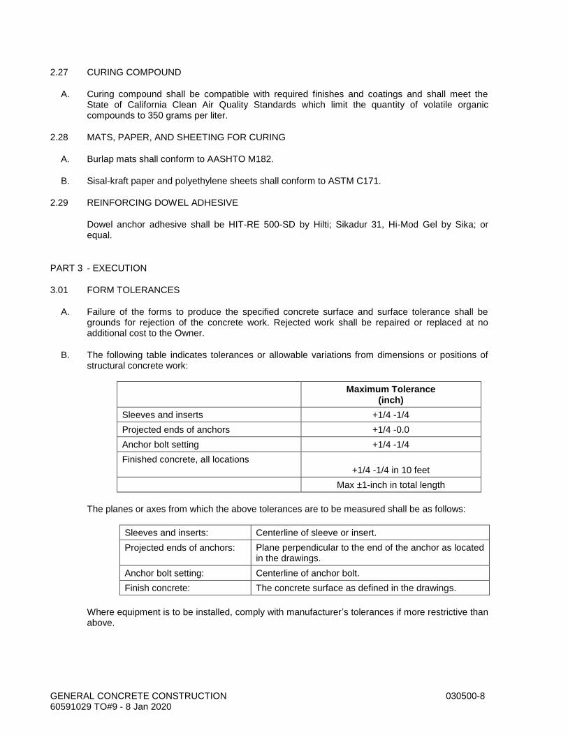
GENERAL CONCRETE CONSTRUCTION 030500-8 60591029 TO#9 - 8 Jan 2020
2.27 CURING COMPOUND
A. Curing compound shall be compatible with required finishes and coatings and shall meet the State of California Clean Air Quality Standards which limit the quantity of volatile organic compounds to 350 grams per liter.
2.28 MATS, PAPER, AND SHEETING FOR CURING
A. Burlap mats shall conform to AASHTO M182.
B. Sisal-kraft paper and polyethylene sheets shall conform to ASTM C171.
2.29 REINFORCING DOWEL ADHESIVE
Dowel anchor adhesive shall be HIT-RE 500-SD by Hilti; Sikadur 31, Hi-Mod Gel by Sika; or equal.
PART 3 - EXECUTION
3.01 FORM TOLERANCES
A. Failure of the forms to produce the specified concrete surface and surface tolerance shall be grounds for rejection of the concrete work. Rejected work shall be repaired or replaced at no additional cost to the Owner.
B. The following table indicates tolerances or allowable variations from dimensions or positions of structural concrete work:
Maximum Tolerance (inch)
Sleeves and inserts +1/4 -1/4
Projected ends of anchors +1/4 -0.0
Anchor bolt setting +1/4 -1/4
Finished concrete, all locations +1/4 -1/4 in 10 feet
Max ±1-inch in total length
The planes or axes from which the above tolerances are to be measured shall be as follows:
Sleeves and inserts: Centerline of sleeve or insert.
Projected ends of anchors: Plane perpendicular to the end of the anchor as located in the drawings.
Anchor bolt setting: Centerline of anchor bolt.
Finish concrete: The concrete surface as defined in the drawings.
Where equipment is to be installed, comply with manufacturer’s tolerances if more restrictive than above.
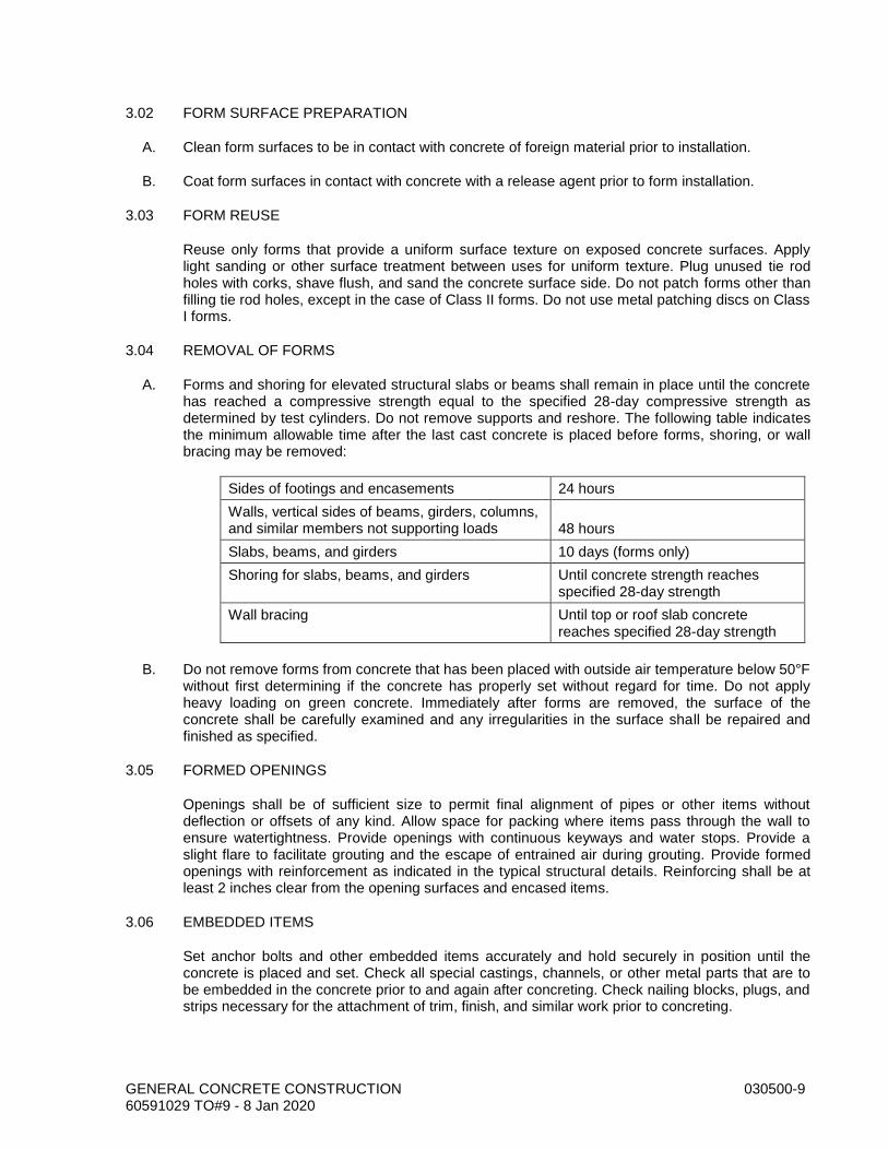
GENERAL CONCRETE CONSTRUCTION 030500-9 60591029 TO#9 - 8 Jan 2020
3.02 FORM SURFACE PREPARATION
A. Clean form surfaces to be in contact with concrete of foreign material prior to installation.
B. Coat form surfaces in contact with concrete with a release agent prior to form installation.
3.03 FORM REUSE
Reuse only forms that provide a uniform surface texture on exposed concrete surfaces. Apply light sanding or other surface treatment between uses for uniform texture. Plug unused tie rod holes with corks, shave flush, and sand the concrete surface side. Do not patch forms other than filling tie rod holes, except in the case of Class II forms. Do not use metal patching discs on Class I forms.
3.04 REMOVAL OF FORMS
A. Forms and shoring for elevated structural slabs or beams shall remain in place until the concrete has reached a compressive strength equal to the specified 28-day compressive strength as determined by test cylinders. Do not remove supports and reshore. The following table indicates the minimum allowable time after the last cast concrete is placed before forms, shoring, or wall bracing may be removed:
Sides of footings and encasements 24 hours
Walls, vertical sides of beams, girders, columns, and similar members not supporting loads 48 hours
Slabs, beams, and girders 10 days (forms only)
Shoring for slabs, beams, and girders Until concrete strength reaches specified 28-day strength
Wall bracing Until top or roof slab concrete reaches specified 28-day strength
B. Do not remove forms from concrete that has been placed with outside air temperature below 50°F without first determining if the concrete has properly set without regard for time. Do not apply heavy loading on green concrete. Immediately after forms are removed, the surface of the concrete shall be carefully examined and any irregularities in the surface shall be repaired and finished as specified.
3.05 FORMED OPENINGS
Openings shall be of sufficient size to permit final alignment of pipes or other items without deflection or offsets of any kind. Allow space for packing where items pass through the wall to ensure watertightness. Provide openings with continuous keyways and water stops. Provide a slight flare to facilitate grouting and the escape of entrained air during grouting. Provide formed openings with reinforcement as indicated in the typical structural details. Reinforcing shall be at least 2 inches clear from the opening surfaces and encased items.
3.06 EMBEDDED ITEMS
Set anchor bolts and other embedded items accurately and hold securely in position until the concrete is placed and set. Check all special castings, channels, or other metal parts that are to be embedded in the concrete prior to and again after concreting. Check nailing blocks, plugs, and strips necessary for the attachment of trim, finish, and similar work prior to concreting.

GENERAL CONCRETE CONSTRUCTION 030500-10 60591029 TO#9 - 8 Jan 2020
3.07 BEVELED EDGES (CHAMFER)
Form 3/4-inch beveled edges on exposed concrete edges and corners, beam soffit corners, and where indicated in the drawings. Reentrant corners in concrete members shall not have fillets, unless otherwise shown in the drawings. The top edges of slabs, walkways, beams, and walls may be beveled with an edging trowel in lieu of using chamfer strips.
3.08 CONSTRUCTION JOINTS
A. Provide construction joints in accordance with the following:
1. Slabs: Maximum spacing of 20 feet on center in each direction in plan.
For purposes of maximum spacing requirements, expansion joints are considered to be construction joints.
The foregoing applies unless otherwise indicated in the drawings.
B. For slabs-on-grade that are not subject to hydraulic loading, use formed construction joints. Maximum size of pour shall be 30 feet each way for slabs with wire mesh reinforcement and 75 feet each way for slabs with bar reinforcement. Allow 24 hours between pours of adjacent slabs. Provide joints as specified or shown. Set continuous expansion joint strips between slabs and abutting vertical surfaces as indicated in the drawings.
C. Place expansion joint fillers every 30 feet in straight runs of walks, at right-angle turns, and wherever concrete walks butt into vertical surfaces. ints shall be keyed, unless otherwise detailed. Form keyways by beveled strips or boards placed at right angles to the direction of shear. Except where otherwise shown in the drawings or specified, keyways shall be at least 1 1/2 inches in depth over at least 25% of the area of the section.
D. When it is necessary to make a joint because of an emergency, furnish and place reinforcing dowels across the joint normal to the face of joint created if not normal to specified reinforcement and at the centerline of the concrete section being terminated. Carefully remove set concrete to a plane but rough surface near normal to adjacent formed or finish surfaces. Embed and extend dowels 48 bar diameters each side of the joint. Size and spacing of dowels shall match the largest reinforcing in the member but no closer than 6 inches on center. Furnishing and placing such reinforcing steel shall be at the Contractor’s expense.
E. After a concrete placement pour has been completed to the construction joint and the concrete has hardened, thoroughly clean the entire surface of the joint of surface laitance, loose or defective concrete, and foreign material. Expose clean aggregate by sandblasting and thoroughly cleaning the surface of construction joints before placing the new concrete. Cover horizontal construction joints with grout bedding. Spread uniformly and work thoroughly into all irregularities of the surface. The consistency of the mortar shall be suitable for placing and working and shall be placed immediately prior to placing new concrete.
F. In case of emergency, place additional construction joints. (An interval of 45 minutes constitutes cause for an emergency construction joint.)
3.09 EXPANSION JOINTS
Provide expansion joints with continuous edge reservoirs, which shall be filled with a joint sealant. Leave the material used for forming the reservoirs in place until immediately before the grooves are cleaned and filled with joint sealant. After removing edge forms from the reservoir, remove grout, loose concrete, and fins; then sandblast the slots. Allow the reservoirs to become

GENERAL CONCRETE CONSTRUCTION 030500-11 60591029 TO#9 - 8 Jan 2020
thoroughly dry; then blow out the reservoirs and immediately prime and fill with the expansion joint sealant and backup materials. The primer used shall be supplied by the same manufacturer supplying the joint sealant.
3.10 TIME BETWEEN POURS
At least two hours shall elapse after depositing concrete in the columns or walls before depositing in beams, girders, or slabs supported thereon. Place beams, girders, brackets, column capitals, and haunches monolithically as part of the floor or roof system, unless otherwise indicated in the drawings.
3.11 INSTALLATION OF PREMOLDED JOINT FILLER
Install in joint accurately as shown. Attach to concrete with a bonding agent recommended by the joint sealant and joint filler manufacturer for compatibility.
3.12 INSTALLATION OF JOINT SEALANTS
A. Immediately before installing the joint sealant, clean the joint cavity by sandblasting or power wire brushing. Install bond breaker tape per manufacturer’s instructions.
B. After the joints have been prepared as described above, apply the joint sealant. Apply the primer, if required, and joint sealant only with the equipment and methods recommended by the joint sealant manufacturer. Application criteria for the sealant materials, such as temperature and moisture requirements and primer cure time, shall be in accordance with the recommendations of the sealant manufacturer.
C. Apply masking tape along the edges of the exposed surface of the exposed joints. Trowel the joints smooth with a tuck pointing tool wiped with a solvent recommended by the sealant manufacturer.
D. After the sealant has been applied, remove the masking tape and any sealant spillage.
3.13 PLACING REINFORCEMENT
A. Place reinforcing steel in accordance with the current edition of Recommended Practice for Placing Reinforcing Bars, published by the Concrete Reinforcing Steel Institute.
B. Place reinforcing in accordance with the following, unless otherwise indicated:
1. Reinforcement indicated in the drawings is continuous through the structure to the farthest extent possible. Terminate bars and hooks 2 inches clear from faces of concrete.
2. Splices may be used to provide continuity due to bar length limitations. Minimum length of bars spliced for this reason is 30. Splicing of reinforcement that is detailed to be continuous in the drawings is not permitted.
C. Reinforcing steel, before being positioned and just prior to placing concrete, shall be free from loose mill and rust scale and from any coatings that may destroy or reduce the bond. Clean reinforcing steel by sandblasting or wire brushing and remove mortar, oil, or dirt to remove materials that may reduce the bond.
D. Do not straighten or rebend reinforcing steel in the field. rage. Bars, in addition to those shown in the drawings, which may be found necessary or desirable by the Contractor for the purpose of securing reinforcement in position shall be provided by the Contractor at his own expense.

GENERAL CONCRETE CONSTRUCTION 030500-12 60591029 TO#9 - 8 Jan 2020
E. Place reinforcement a minimum of 2 inches clear of any metal pipe or fittings.
F. Secure reinforcing dowels in place prior to placing concrete. Do not press dowels into the concrete after the concrete has been placed.
G. Roll wire mesh used for reinforcement flat before placing concrete. Support and tie wire mesh to prevent movement during concrete placement.
H. Position dowels for masonry walls to occur at reinforced block cells.
3.14 SITE-MIXED CONCRETE
Conform to ACI 304.
3.15 READY-MIXED CONCRETE
Conform to ASTM C94.
3.16 PLACING CONCRETE
Conform to ACI 304.
3.17 PUMPING CONCRETE
Conform to ACI 304.2R-91.
3.18 WEATHER REQUIREMENTS
A. Conform to ACI 305 for placing during hot weather.
B. Conform to ACI 306 for placing during cold weather.
3.19 BONDING TO OLD CONCRETE
Coat the contact surfaces of structural sections with epoxy bonding compound when noted in the drawings. The method of preparation and application of the bonding compound shall conform to the manufacturer’s printed instructions and recommendations for specific application for this project.
3.20 GROUTING MACHINERY FOUNDATIONS
Block out the original concrete or finish off a sufficient distance below the bottom of the machinery base to provide for the thickness of grout shown in the drawings. After the machinery has been set in position and placed at the proper elevation by steel wedges, fill the space between the bottom of the machinery base and the original pour of concrete with a pourable nonshrink grout. Grout and grouting procedure shall be in accordance with API 686, Chapter 4, paragraphs 3.6 and 3.7, and Chapter 5.
3.21 BACKFILL AGAINST WALLS
A. Do not place backfill against walls until the concrete has obtained a compressive strength equal to the specified 28-day compressive strength. Where backfill is to be placed on both sides of the wall, place the backfill uniformly on both sides.

GENERAL CONCRETE CONSTRUCTION 030500-13 60591029 TO#9 - 8 Jan 2020
B. Do not backfill the walls of structures that are laterally restrained or supported by suspended slabs or slabs on grade until the slab is poured and the concrete has reached the specified compressive strength.
3.22 PLACING SLURRY CEMENT BACKFILL
Place slurry cement backfill in a uniform manner that will prevent voids in, or segregation of, the backfill. Remove foreign material that falls into the excavation or trench. Do not commence backfilling over or place any material over the slurry cement backfill until at least four hours after placing the slurry cement backfill, except that when concrete sand is used for the aggregate and the in-place material is free draining, backfilling may commence as soon as the surface water is gone.
3.23 CONCRETE FINISHES
A. Complete concrete surfaces in accordance with the following schedule:
Finish Designation Area Applied
F-1 Beams, columns, and exterior walls not exposed to view.
F-3 Beams, columns, and walls of structures or buildings exposed to view. Underside of formed floors or slabs.
F-4 Exterior and interior surfaces to be coated.
S-1 Slabs and floors to be covered with concrete or grout.
S-4 Slabs and floors of structures or buildings exposed to view.
S-5 Slabs and floors at slopes greater than 10% and stairs.
E-1 Exposed edges. EXCEPTION: edges normally covered with earth.
E-2 Top of walls, beams, and similar unformed surfaces.
B. Finish F-1: Repair defective concrete, fill depressions deeper than 1/2 inch, and fill tie holes.
Finish F-3: In addition to Finish F-1, remove fins, fill depressions 1/4 inch or deeper, fill depressions and airholes with mortar. Dampen surfaces and then spread a slurry consisting of one part cement and one and one-half parts sand by damp loose volume, over the surface with clean burlap pads or sponge rubber floats. Remove any surplus by scraping and then rubbing with clean burlap.
Finish F-4: Repair defective concrete, remove fins, fill depressions 1/16 inch or deeper, fill tie holes, remove mortar spatter, and remove bulges higher than 1/16 inch.
Finish S-1: Screed to grade without special finish.
Finish S-4: Steel trowel finish without local depressions or high points and apply a light hair-broom finish. Do not use stiff bristle brooms or brushes. Leave hair-broom lines parallel to the direction of slab drainage.
Finish S-5: Steel trowel finish without local depressions or high points. Apply a stiff bristle broom finish. Leave broom lines parallel to the direction of slope drainage.
Finish E-1: Provide chamfer or beveled edges.
Finish E-2: Strike smooth and float to an F-3 or F-4 finish.
GENERAL CONCRETE CONSTRUCTION 030500-14 60591029 TO#9 - 8 Jan 2020
3.24 CURING CONCRETE
A. Conform to ACI 308.
B. Water cure with burlap mats unless optional curing methods are permitted.
C. It is the responsibility of the Contractor to select the appropriate curing method in response to climatical and/or site conditions occurring at the time of concrete placement. Take appropriate measures as described in ACI 305 and 306 for protecting and curing concrete during hot and cold weather.
3.25 REPAIR OF DEFECTS AND CRACKS
A. Do not repair defects until concrete has been evaluated by the Owner’s Representative.
B. Surface Defects:
1. Repair surface defects that are smaller than 1 foot across in any direction and are less than 1/2 inch in depth.
2. Repair by removing the honeycombed and other defective concrete down to sound concrete, cut or grind edges perpendicular to the surface and at least 3/8 inch deep, abrasive clean and thoroughly dampen the surface, work into the surface an epoxy bonding agent, and fill the hole with one part cement to one part fine sand. Match the finish on the adjacent concrete, and cure as specified.
C. Severe Defects:
1. Repair severe defects that are larger than surface defects but do not appear to affect the structural integrity of the structure.
2. Repair by removing the honeycombed and other defective concrete down to sound concrete, make edges of the repair area perpendicular to the surface, as required above, sandblast the sound concrete surface, coat the exposed surfaces with epoxy bonding compound, place nonshrink grout, match the finish on the adjacent concrete, and cure as specified.
D. Repair minor cracks in concrete structures that are wider than 1/10 inch by cutting out a square edged and uniformly aligned joint 3/8 inch wide by 3/4 inch deep, preparing exposed surfaces of the joint, priming the joint, and applying polyurethane joint sealant.
E. If the cracks are major or affect the hydraulic capacity or function of the element, the Owner’s Representative may require the concrete to be repaired by epoxy injection.
F. Major Defects and Cracks: If the defects affect the structural integrity of the structure or if patching does not satisfactorily restore quality and appearance to the surface, the Owner’s Representative may require the concrete to be removed and replaced, complete.
G. Apply hardener to the surfaces designated in the drawings.
3.26 ALUMINUM SURFACES IN CONTACT WITH CONCRETE
Coat aluminum surfaces in contact with concrete per Section 099000, System No. 51 or 54.
GENERAL CONCRETE CONSTRUCTION 030500-15 60591029 TO#9 - 8 Jan 2020
3.27 CONCRETE TESTS
A. Concrete quality testing will be performed on the concrete by the Owner as follows:
1. Frequency of Sampling: Cast four concrete test cylinders from each 50 cubic yards, or fraction thereof, of each class of concrete placed in any one day. Sampling and curing of cylinders shall conform to ASTM C31.
2. Strength Testing: Test cylinders in accordance with ASTM C39. Test one cylinder at 7 days for information; test two cylinders at 28 days for acceptance; and hold one cylinder for verification. Strength acceptance will be based on the average of the strengths of the two cylinders tested at 28 days. If one cylinder of a 28-day test manifests evidence of improper sampling, molding, or testing, other than low strength, discard it and use the fourth cylinder for the test result.
3. Determine concrete slump by ASTM C143 with each strength test sampling and as required to establish consistency.
4. Determine air content of the concrete using ASTM C231 to verify the percentage of air in the concrete immediately prior to depositing in forms.
B. To facilitate concrete sampling and testing, the Contractor shall:
1. Furnish labor to assist the Owner in obtaining and handling samples at the project site.
2. Advise the Owner in advance of concrete placing operations to allow for scheduling and completion of quality testing.
3. Provide and maintain facilities for safe storage and proper curing of concrete test specimens on the project site, as required by ASTM C31.
END OF SECTION

GENERAL CONCRETE CONSTRUCTION 030500-16 60591029 TO#9 - 8 Jan 2020
THIS PAGE INTENTIONALLY LEFT BLANK

PRECAST CONCRETE VAULTS 034220-1 60591029 TO#9 - 8 Jan 2020
SECTION 034220 PRECAST CONCRETE VAULTS
PART 1 - GENERAL
1.01 DESCRIPTION
This section includes materials, design, and installation of precast concrete vaults and structures.
1.02 RELATED WORK SPECIFIED ELSEWHERE
A. General Concrete Construction: 030500.
B. Precast Circular Concrete Manholes: 034230.
C. Grating, Cover Plates, and Access Hatches: 055300.
D. Earthwork: 312300.
1.03 SUBMITTALS
A. Submit shop drawings in accordance with the Special Provisions.
B. Submit manufacturer's catalog data on precast concrete items. Show dimensions of vaults and thicknesses of walls, floors, and top slabs. Show reinforcing wire and steel. Show materials of construction by ASTM reference and grade.
PART 2 - MATERIALS
2.01 MANUFACTURERS
Precast concrete vaults shall be manufactured by Brooks Products Inc., Utility Vault Company, or equal.
2.02 PRECAST CONCRETE VAULTS
A. Precast concrete vaults shall comply with ASTM C858 except as modified herein.
B. Design loads shall be in accordance with ASTM C857, except as modified herein. Traffic loads, unless otherwise stated, shall conform to Load Designation A-16 per Table 1. Soil lateral loads shall be as determined by ASTM C857 or loadings specified in the project soils report, whichever is greater. Alternate design by the strength design method shall include a load factor of 1.7 times the lateral earth or hydrostatic pressures.
C. Include the following load conditions in the design:
1. Vault roof removed while structure is backfilled to grade and subject to live and dead loads.
2. Vault roof in place and walls subject to simultaneous vertical and horizontal application of all live, impact, and dead loads. Include the case of an A-16 designated load placed directly above the wall.

PRECAST CONCRETE VAULTS 034220-2 60591029 TO#9 - 8 Jan 2020
D. Design shall also comply with the following restrictions:
1. The maximum reinforcement ratio allowed is one-half the reinforcement ratio that would produce a balanced strain condition.
2. Earth pressure shall be converted to a horizontal pressure using a coefficient of earth pressure at rest of 0.5 and not a coefficient of active earth pressure.
3. Include a live load surcharge of 2 feet of soil in the design of the walls.
E. Design all vaults to receive the specified traffic loading.
F. Precast vault construction shall be in the form of monolithic walls or horizontal wall sections; do not use panel walls.
G. Minimum wall thickness shall be 6 inches. Design knockout wall panels to accommodate loading pressures defined above.
H. Floor slab shall be precast concrete as shown in the drawings. Design joints using a butyl rubber sealant per ASTM C990.
2.03 SEALANTS AND MORTAR
Butyl rubber sealing compound shall comply with ASTM C990. Mortar shall comply with ASTM C387, Type S or use grout complying with Section 030500.
2.04 ACCESS HATCHES
A. Provide traffic-rated access hatches per Section 055300.
2.05 CEMENT
Cement shall be ASTM C150, Type II.
2.06 ADMIXTURES
Provide air-entraining and water-reducing concrete admixtures as specified in Section 030500
2.07 CRUSHED ROCK BASE
Crushed rock base material shall comply with Section 312323.
PART 3 - EXECUTION
3.01 VAULT BASE
A. Excavate for the vault and install a crushed rock base per Section 312323, 12 inches thick.
B. Crushed rock base material shall extend 1 foot beyond the outside edge of the concrete vault base. Compact to 90% relative density.
3.02 SEALING AND GROUTING
Fill joints between precast sections with either a butyl rubber sealing compound or mortar.

PRECAST CONCRETE VAULTS 034220-3 60591029 TO#9 - 8 Jan 2020
3.03 INSTALLING VAULTS
A. After the excavation has been completed, level the area where the base section is to be installed. Fill and compact the base material and provide a level and solid foundation. Set the base such that water will drain toward the sumps.
B. Assemble the vault sections by lowering onto the preceding base or section. Set level and firmly position the base or preceding section before placing additional sections.
C. Set each precast concrete vault section plumb on a bed of sealant or cement mortar at least 1/2-inch thick to make a watertight joint with the concrete base and with the preceding unit. Remove foreign materials such as dirt, mud, and stones from joint surfaces. Apply grout or sealant such that no voids occur. Point the inside joint and wipe off the excess mortar or sealant.
D. If a misalignment of sections occurs during the installation, remove and reinstall the section. Do not reinstall damaged sections. If the sealing material is damaged, clean the joint surfaces before repairing or placing new sealing material.
E. Install the concrete roof such that it slopes at least 1/8 inch per foot.
3.04 BACKFILL AROUND VAULTS
Backfill and compact around the vaults using fill as specified in Section 312300. Compact to 90% relative compaction.
END OF SECTION

PRECAST CONCRETE VAULTS 034220-4 60591029 TO#9 - 8 Jan 2020
THIS PAGE INTENTIONALLY LEFT BLANK

PRECAST CIRCULAR CONCRETE MANHOLES AND WET WELLS 034230-1 60591029 TO#9 - 8 Jan 2020
SECTION 034230 PRECAST CIRCULAR CONCRETE MANHOLES AND WET WELLS
PART 1 - GENERAL
1.01 DESCRIPTION
This section includes design, materials, testing, and installation of precast circular concrete wet wells.
1.02 RELATED WORK SPECIFIED ELSEWHERE
A. General Concrete Construction: 030500.
B. Grating, Cover Plates, and Access Hatches: 055300.
C. Earthwork: 312300.
D. Trenching, Backfilling, and Compacting: 312316.
E. Gravel and Crushed Rock Base for Structures: 312323.
1.03 SUBMITTALS
A. Submit shop drawings in accordance with the Special Provisions.
B. Submit manufacturer's catalog data for precast concrete wet wells, frames, and covers. Show dimensions and materials of construction by ASTM reference and grade. Show lettering on manhole covers.
PART 2 - MATERIALS
2.01 PRECAST CIRCULAR CONCRETE WET WELLS
A. Precast circular concrete wet wells shall comply with ASTM C76. Design wet wells for the depths shown in the drawings, assuming a soil density of 130 pounds per cubic foot. Design wet well to resist flotation under the conditions of empty wet well and groundwater level from the wet well base to finish grade.
B. Wet well material:
1. Concrete shall add Xypex Bio-San C500 admixture or equal
2. 1 (one) percent by weight or as specified by the manufacturer.
C. Minimum wall thickness and minimum allowable steel shall be in accordance with ASTM C76, Class III, Wall “A” with double circular cage reinforcing.
D. Precast top sections shall be as shown on the drawings.
E. Provide precast, reinforced base with a rubber gasket connection to the lower wet well section.
F. Manufacturers: Jensen Precast, Concrete Pipe Division; Oldcastle Infrastructure or equal.

PRECAST CIRCULAR CONCRETE MANHOLES AND WET WELLS 034230-2 60591029 TO#9 - 8 Jan 2020
2.02 STEPS OR RUNGS
Cast wet wells without steps (ladder rungs).
2.03 DESIGN OF TOP SECTION AND PRECAST BASE
Design loads shall be in accordance with ASTM C857, except as modified herein. Traffic loads, unless otherwise stated, shall conform to Load Designation A-16 per Table 1.
2.04 FRAMES AND COVERS
A. Frames and covers shall be made of cast iron conforming to ASTM A48, Class 30. Castings shall be smooth, clean, and free from blisters, blowholes, and shrinkage Design frames and covers access hatches for H20-44 traffic loads. The cover shall seat firmly into the frame without rocking. Cast the frame into the top slab.
B. Finish each cover and access hatch so that it will fit in its frame without rocking. Modify word cast on cover in paragraph below to suit project. Show a detail in the drawings for any special lettering.
C. Covers shall have the word “SEWER” and the letters as indicated in the drawings cast thereon. Do not apply any other lettering.
2.05 ACCESS HATCH
A. When shown on the drawings, provide access hatch per Section 055300.
2.06 SECTIONS OR RISER JOINTS
Joints shall be of the rubber-gasket type, requiring no field-applied sealant. Gaskets and joints shall comply with ASTM C443.
2.07 PIPE CONNECTIONS FOR INLET PIPING
Provide resilient watertight connectors between the wet well or manhole and inlet piping in accordance with ASTM C923. Connections shall consist of a chemically resistant neoprene EPDM flexible boot, locking ring, and pipe clamp(s). The locking ring shall be stainless steel and shall lock the boot into the preformed opening in the manhole. The pipe clamp shall be stainless steel. Alternatively, cast the flexible boot in the wet well and eliminate the locking ring. Pipe connections shall be Kor-N-Seal (Dukor Corporation), Z-Lok-XP (A-Lok Products, Inc.), or equal.
2.08 CRUSHED ROCK FOR WET WELL BASE
Crushed rock shall comply with Section 312323.
2.09 CONCRETE
Concrete for wet wells and precast bases shall be Type I per ASTM C150 and C595.
PART 3 - EXECUTION
3.01 WET WELL BASE
Excavate for the wet well and install a crushed rock base per Section 312323.
PRECAST CIRCULAR CONCRETE MANHOLES AND WET WELLS 034230-3 60591029 TO#9 - 8 Jan 2020
3.02 INSTALLING WET WELLS
A. Set each precast concrete wet well sectional unit plumb to make a watertight joint with the precast concrete base or with the preceding sectional unit. Backfill, compact, and replace pavement.
B. Assemble sectional units so that the top slab conforms to the elevation determined by the wet well location as follows:
1. In Paved Areas: Top of slab shall be flush with the paving surface.
2. In Shoulder Areas: Top of slab shall be flush with existing surface where it is in traveled way of shoulder and 0.1 foot above existing surface where it is outside limits of traveled way but not in unpaved open areas.
3. In Unpaved Open Areas: Top of slab shall be 12 inches above the ground surface.
3.03 LEAKAGE TESTING
Perform testing before backfilling the wet well. Plug the pipes connected to the wet well. Fill the wet well with water to a point 1 foot below the top slab soffit or a maximum water depth of 30 feet. Allow the wet well to absorb water for four hours, then refill to the original water level. Allowable leakage shall be zero, except that moisture or beads of water appearing on the surface of the joint will not be considered leakage. Duration of leakage test shall be four hours. If the allowable leakage rate is exceeded, repair or replace the wet well and retest.
3.04 BACKFILL AROUND WET WELLS
Backfill and compact around the wet wells using native material, per Section 312300.
END OF SECTION

PRECAST CIRCULAR CONCRETE MANHOLES AND WET WELLS 034230-4 60591029 TO#9 - 8 Jan 2020
THIS PAGE INTENTIONALLY LEFT BLANK

BOLTS, WASHERS, ANCHORS, AND EYEBOLTS 050520-1 60591029 TO#9 - 8 Jan 2020
SECTION 050520 BOLTS, WASHERS, ANCHORS, AND EYEBOLTS
PART 1 - GENERAL
1.01 DESCRIPTION
This section describes materials and installation of anchor bolts, connecting bolts, washers, drilled anchors, epoxy anchors, screw anchors, eyebolts, and stainless steel fasteners.
1.02 RELATED WORK SPECIFIED ELSEWHERE
A. General Concrete Construction: 030500.
B. General Piping Requirements: 400500.
1.03 DESIGN CRITERIA
Structural Connections: AISC Specification for Structural Steel Buildings (March 9, 2005), except connection details are shown in the contract drawings.
1.04 SUBMITTALS
A. Submit shop drawings in accordance with the Special Provisions.
B. Submit manufacturer's catalog data and ICC reports for bolts, washers, and concrete anchors. Show dimensions and reference materials of construction by ASTM designation and grade.
PART 2 - MATERIALS
2.01 ANCHOR BOLTS
Steel anchor bolts shall conform to ASTM A307, Grade A, B, or C.
2.02 CONNECTION BOLTS
A. Steel connection bolts shall conform to ASTM A307.
B. Provide galvanized bolts where shown in drawings. Galvanizing of bolts, nuts, and washers shall be in accordance with ASTM F2329.
2.03 STAINLESS STEEL BOLTS
Stainless steel bolts shall be ASTM A193, Grade B8 or ASTM F593, Type 316. Nuts shall be ASTM A194, Grade 8 or ASTM F594, Type 316. Use ASTM A194 nuts with ASTM A193 bolts; use ASTM F594 nuts with ASTM F593 bolts. Provide washer for each nut and bolthead. Washers shall be of the same material as the nuts.
2.04 LUBRICANT FOR STAINLESS STEEL BOLTS AND NUTS
Lubricant shall be chloride free and shall be RAMCO TG-50, Anti-Seize by RAMCO, Specialty
Lubricants Corporation Husky Lube O'Seal, or equal.
BOLTS, WASHERS, ANCHORS, AND EYEBOLTS 050520-2 60591029 TO#9 - 8 Jan 2020
2.05 PLAIN UNHARDENED STEEL AND STAINLESS STEEL WASHERS
Washers shall comply with ASTM F844. Stainless steel washers shall be Type 316. Provide clipped washers where space limitations necessitate.
2.06 DRILLED ANCHORS
A. Unless otherwise indicated in the drawings, drilled anchors shall be 316 stainless steel wedge anchors as manufactured by ITW Ramset/Redhead, Kwik Bolt TZ by Hilti, or equal.
2.07 EPOXY ANCHORS
A. Epoxy anchors in concrete shall be 316 stainless steel threaded rod adhesive anchors. Adhesive shall be Rawl Power-Fast, Hilti HIT RE 500-SD, Simpson SET-XP, or equal.
PART 3 - EXECUTION
3.01 STORAGE OF MATERIALS
Store material, either plain or fabricated, above ground on platforms, skids, or other supports. Keep material free from dirt, grease, and other foreign matter and protect from corrosion.
3.02 GALVANIZING
Zinc coating for bolts, anchor bolts, and threaded parts shall be in accordance with ASTM F2329.
3.03 INSTALLING CONNECTION BOLTS
A. Use steel bolts to connect structural steel members. Use stainless steel bolts to connect structural aluminum members.
B. Install washers per AISC Specification for ASD.
C. Bolt holes in structural members shall be 1/16 inch in diameter larger than bolt size. Measure cast-in-place bolt locations in the field before drilling companion holes in structural steel beam or assembly.
D. Bolts shall be of the length that will extend entirely through but not more than 1/4 inch beyond the nuts.
3.04 INSTALLING ANCHOR BOLTS
A. Preset bolts and anchors by the use of templates. For mechanical equipment (pumps, compressors, and blowers), do not use concrete anchors set in holes drilled in the concrete after the concrete is placed.
B. After anchor bolts have been embedded, protect projecting threads by applying grease and having the nuts installed until the time of installation of the equipment or metalwork.
C. Minimum depth of embedment of drilled mechanical anchors shall be as recommended by the manufacturer.
D. Minimum depth of embedment of epoxy anchors shall be as recommended by the manufacturer, but no less than that shown in the drawings.

BOLTS, WASHERS, ANCHORS, AND EYEBOLTS 050520-3 60591029 TO#9 - 8 Jan 2020
E. Prepare holes for drilled and epoxy anchors in accordance with the anchor manufacturer’s recommendations prior to installation.
3.05 INSTALLATION OF STAINLESS STEEL BOLTS AND NUTS
Prior to assembly, coat threaded portions of stainless steel bolts and nuts with lubricant.
END OF SECTION

BOLTS, WASHERS, ANCHORS, AND EYEBOLTS 050520-4 60591029 TO#9 - 8 Jan 2020
THIS PAGE INTENTIONALLY LEFT BLANK

GRATING, COVER PLATES, AND ACCESS HATCHES 055300-1 60591029 TO#9 - 8 Jan 2020
SECTION 055300 GRATING, COVER PLATES, AND ACCESS HATCHES
PART 1 - GENERAL
1.01 DESCRIPTION
This section describes materials, fabrication, and installation of steel and aluminum grating, cover and floor plates, and access hatches.
1.02 RELATED WORK SPECIFIED ELSEWHERE
A. General Concrete Construction: 030500
B. Painting and Coating: 099000.
1.03 DESIGN CRITERIA
A. Access Hatches:
1. LS 9 and LS 55: 300 psf
2. LS 42 AASHTO H20 loading. As noted in the drawings.
1.04 SUBMITTALS
A. Submit shop drawings in accordance with the Special Provisions.
B. Submit drawings of grating, cover plates, and access hatches. Show dimensions and reference materials of construction by ASTM designation and grade. Show design criteria.
PART 2 - MATERIALS
2.01 ALUMINUM STEEL ACCESS HATCHES
A. Access hatches shall be Bilco Type JAL of the size and configuration shown in the drawings. Latch and lifting mechanism assemblies, hold-open arms and guides, and brackets, hinges, pins, and fasteners shall be Type 316 stainless steel.
B. Locking and Latching Devices: Recessed hasp covered by a hinged lid flush with the exterior surface.
2.02 STEEL ACCESS HATCH (LS 42 ONLY)
A. Access hatches shall be steel Bilco Type JAL of the size and configuration shown in the drawings. Steel doors and frames shall be hot-dipped galvanized per ASTM A123. Latch and lifting mechanism assemblies, hold-open arms and guides, and brackets, hinges, pins, and fasteners shall be Type 316 stainless steel.
B. Locking and Latching Devices:
1. Recessed hasp covered by a hinged lid flush with the exterior surface.

GRATING, COVER PLATES, AND ACCESS HATCHES 055300-2 60591029 TO#9 - 8 Jan 2020
2.03 PROTECTIVE GRATE FOR ACCESS HATCHES AND EXISTING ACCESS HATCH OPENINGS
Provide hinged grating panel to cover each access hatch opening and existing access hatch opening. The grating panel shall fit beneath the access hatch cover. Provide Type 316 stainless steel hold-open arm with aluminum latch, Type 316 stainless steel hardware including mounting hardware and supports and aluminum grating with OSHA Safety Orange fusion-bonded coating. Provide spring-loaded lifting handle.
2.04 GRATING
Grating shall be fiberglass reinforced plastic.
1. Grating shall be a minimum of 1-1/2-inches thick with a square grid pattern.
2. Support 200 psf load with a maximum deflection of 0.25-inch
2.05 WELDING ELECTRODES
A. Welding electrodes for structural steel shall conform to AWS A5.5. Use electrodes in the E-70 series.
B. Welding electrode for aluminum shall be ER4043 filler metal.
C. Welding electrodes for stainless steel shall conform to AWS A5.4. Use electrodes as follows:
Stainless Steel Material Welding Electrode Material
Type 304 E 308
Type 304L E 347
Type 316 E 316
Type 316L E 318
PART 3 - EXECUTION
3.01 STORAGE OF MATERIALS
Store structural material, either plain or fabricated, above ground on platforms, skids, or other supports. Keep material free from dirt, grease, and other foreign matter and protect from corrosion.
3.02 INSTALLATION AND ERECTION
A. Clean the surfaces of metalwork to be in contact with concrete of rust, dirt, grease, and other foreign substances before placing concrete.
B. Set grating seats and frames and checkered plate frames and supports accurately in position when concrete is placed and support it rigidly to prevent displacement or undue vibration during or after the placement of concrete. Unless otherwise specified, where metalwork is to be installed in recesses in formed concrete, said recesses shall be made, metalwork installed, and recesses filled with dry-pack mortar in conformance with Section 030500.

GRATING, COVER PLATES, AND ACCESS HATCHES 055300-3 60591029 TO#9 - 8 Jan 2020
3.03 GALVANIZING
Zinc coating for plates, bolts, anchor bolts, and threaded parts shall be in accordance with ASTM A153 and F2329.
3.04 WELDING
A. Perform welding on steel by the SMAW process. Welding shall conform to AWS D1.1-2006, except as modified in AISC Section J2.
B. Perform welding on aluminum by the gas metal arc (MIG) or gas tungsten arc (TIG) process. Welding shall conform to AWS D1.2-2003.
C. Perform welding on stainless steel by the gas tungsten arc (TIG) process. Welds shall be full penetration and smooth. Provide inert gas on the inside of pipe during welding to reduce oxidation.
D. Provide a minimum of two passes for metal in excess of 5/16-inch thickness.
E. Produce weld uniform in width and size throughout its length with each layer of weldment smooth; free of slag, cracks, pinholes, and undercuttings; and completely fused to the adjacent weld beads and base metal. Avoid irregular surface, nonuniform bead pattern, and high crown. Form fillet welds of the indicated size of uniform height and fully penetrating. Accomplish repair, chipping, and grinding of welds in manner that will not gouge, groove, or reduce the base metal thickness.
3.05 REPAIR OF GALVANIZED SURFACES
Repair or replace metal with damaged galvanized surfaces at no additional cost to the Owner. Repair galvanized surfaces per Section 099000, System No. 55.
3.06 CORROSION PROTECTION OF ALUMINUM SURFACES
A. Coat aluminum surfaces to be embedded or which will be in contact with concrete or masonry per Section 099000, System No. 51 or 54 before installation. Allow the coating to dry before the aluminum is placed in contact with the concrete.
B. Where aluminum surfaces come in contact with dissimilar metals, keep the dissimilar metallic surfaces from direct contact by use of neoprene gaskets or washers.
END OF SECTION

GRATING, COVER PLATES, AND ACCESS HATCHES 055300-4 60591029 TO#9 - 8 Jan 2020
THIS PAGE INTENTIONALLY LEFT BLANK
PAINTING AND COATING 099000-1 60591029 TO#9 - 8 Jan 2020
SECTION 099000 PAINTING AND COATING
PART 1 - GENERAL
1.01 DESCRIPTION
A. Submerged metal.
B. Exposed metal.
C. Buried metal.
D. PVC.
E. Metal in contact with concrete.
F. Fusion-bonded epoxy coated steel.
1.02 RELATED WORK SPECIFIED ELSEWHERE
A. General Concrete Construction: 030500.
B. Cold-Applied Wax Tape Coating: 099752.
C. Fusion-Bonded Epoxy Linings and Coatings: 099761.
1.03 SUBMITTALS
A. Submit shop drawings in accordance with the Special Provisions.
B. Submit manufacturer’s data sheets showing the following information:
1. Percent solids by volume.
2. Minimum and maximum recommended dry-film thickness per coat for prime, intermediate, and finish coats.
3. Recommended surface preparation.
4. Recommended thinners.
5. Statement verifying that the specified prime coat is recommended by the manufacturer for use with the specified intermediate and finish coats.
6. Application instructions including recommended equipment and temperature limitations.
7. Curing requirements and instructions.
C. Submit color swatches.
D. Submit certificate identifying the type and gradation of abrasives used for surface preparation.
E. Submit material safety data sheets for each coating.

PAINTING AND COATING 099000-2 60591029 TO#9 - 8 Jan 2020
PART 2 - MATERIALS
2.01 PAINTING AND COATING SYSTEMS
The following index lists the various painting and coating systems by service and generic type:
PAINT COATINGS SYSTEM INDEX
No. Title Generic Coating
Submerged Metal Coating Systems
7. Submerged Metal, Potable or Nonpotable Water Epoxy
Exposed Metal Coating Systems
10. Exposed Metal, Corrosive Environment High-build epoxy (two-coat system)
Buried Metal Coating Systems
21. Buried Metal Epoxy
24. Buried Metal Corrosion-resisting grease
Coating Systems for Nonferrous Metals
51. Aluminum Insulation from Concrete and Carbon Steel
Bituminous
54. Aluminum Insulation from Concrete and Carbon Steel
Epoxy
These systems are specified in detail in the following paragraphs. For each coating, the required surface preparation, prime coat, intermediate coat (if required), topcoat, and coating thicknesses are described. Mil thicknesses shown are minimum dry-film thicknesses.
A. System No. 7--Submerged Metal, Potable or Nonpotable Water:
Type: Epoxy.
Service Conditions: For use with structures, valves, piping, or equipment immersed in potable or nonpotable water.
Surface Preparation: SSPC SP-10.
Coating System: Apply the manufacturer’s recommended number of coats to attain the specified minimum coating thickness. Products: Devoe Bar-Rust 233H, Tnemec N140 or 100, Sherwin-Williams Tank Clad HS B62-80,Carboline Carboguard 891, or equal; 20 mils total. Color of topcoat: white. Each coat shall be different color than the one preceding it.
2.02 EXPOSED METAL COATING SYSTEMS
A. System No. 10--Exposed Metal, Corrosive Environment:
Type: High-build epoxy intermediate coat having a minimum volume solids of 60%, with an inorganic zinc prime coat and a pigmented polyurethane finish coat having a minimum volume solids of 52%.
Service Conditions: For use with metal structures or pipes subjected to water condensation; chemical fumes, such as hydrogen sulfide; salt spray; and chemical contact.

PAINTING AND COATING 099000-3 60591029 TO#9 - 8 Jan 2020
Surface Preparation: SSPC SP-10.
Prime Coat: Self-curing, two-component inorganic zinc-rich coating recommended by the manufacturer for overcoating with a high-build epoxy finish coat. Minimum zinc content shall be 12 pounds per gallon. Apply to a thickness of 3 mils. Products: Tnemec 90E-92, Devoe Catha-Coat 304 or 304V, International Interzinc 22HS, Ameron 9HS, Carboline Carbozinc 11HS, Sherwin-Williams Zinc-Clad II Plus, PPG METALHIDE® 28 Inorganic Zinc-Rich Primer 97-672, or equal.
Intermediate Coat: Tnemec 104, ICI Devoe Devran 224HS or 231, International Interseal 670HS, Ameron 385, Carboline Carboguard 890, Sherwin-Williams Macropoxy 646 B58-600, PPG PITT-GUARD® Direct-to-Rust Epoxy Mastic Coating 97-145 series, or equal; 5 mils.
Finish Coat: Two-component pigmented acrylic or aliphatic polyurethane recommended by the manufacturer for overcoating a high-build epoxy coating. Apply to a thickness of at least 2 mils. Products: Tnemec Series 1075, ICI Devoe Devthane 379, International Interline 990HS, Ameron 450HS, Carboline 133HB or 134HG, Sherwin-Williams Hi-Solids Polyurethane B65-300, PPG PITTHANE® Ultra Gloss Urethane Enamel 95-812 series, or equal.
2.03 BURIED METAL COATING SYSTEMS
A. System No. 21--Buried Metal:
Type: High solids epoxy or phenolic epoxy having a minimum volume solids of 80% (ASTM D2697).
Service Conditions: Buried metal, such as valves, flanges, bolts, nuts, structural steel, and fittings.
Surface Preparation: SSPC SP-10.
Coating System: Apply three or more coats of Ameron 400, Tnemec 104HS or 80, ICI Devoe Bar-Rust 233H, Carboline 890LT, Sherwin-Williams Tank Clad HS B62-80 series, or equal; 30 mils total. Maximum thickness of an individual coating shall not exceed the manufacturer’s recommendation.
B. System No. 24--Buried Metal:
Type: Corrosion-resisting grease.
Service Conditions: Buried metal, such as bolts, bolt threads, tie rods, and nuts.
Surface Preparation: SSPC SP-3 or SP-6.
Coating: NO-OX-ID GG-2 as manufactured by Sanchem, Inc. Apply to a minimum thickness of 1/4 inch.
2.04 COATING SYSTEMS FOR NONFERROUS METALS
A. System No. 51--Aluminum Insulation from Concrete and Carbon Steel:
Type: Bituminous paint having a minimum volume solids of 68% coal-tar pitch based.
Service Conditions: Coat areas of aluminum grating, stairs, structural members or aluminum fabrications, in contact with concrete or carbon steel with this system.

PAINTING AND COATING 099000-4 60591029 TO#9 - 8 Jan 2020
Surface Preparation: Solvent or steam cleaning per SSPC SP-1; do not use alkali cleaning. Then dust blast.
Prime Coat: Apply synthetic resin or epoxy primer to metal surface before finish coats. Products: International Intervinux VTA528/529, or equal. No primer required for Carboline or Tnemec.
Finish Coat: Carboline Bitumastic 50, Tnemec 46-465, International Intertuf 100, or equal. Apply two coats to a minimum dry-film thickness of 12 mils each.
B. System No. 54--Aluminum Insulation from Concrete and Carbon Steel:
Type: High solids epoxy or phenolic epoxy having a minimum volume solids of 80% (ASTM D2697).
Service Conditions: Coat areas of aluminum grating, stairs, structural members or aluminum fabrications, in contact with concrete or carbon steel with this system.
Surface Preparation: Solvent or steam cleaning per SSPC SP-1; do not use alkali cleaning. Then dust blast.
Coating System: Apply three or more coats of Ameron 400, Tnemec Series 135, ICI Devoe Bar-Rust 233H, Sherwin-Williams Macropoxy B58-600, PPG PITT-GUARD® Direct-to-Rust Epoxy Mastic Coating 97-145 series, or equal; 30 mils total. Maximum thickness of an individual coating shall not exceed the manufacturer’s recommendation.
2.05 ABRASIVES FOR SURFACE PREPARATION
A. Abrasives used for preparation of ferrous (excluding stainless steel) surfaces shall be one of the following:
1. 16 to 30 or 16 to 40 mesh silica sand or mineral grit.
2. 20 to 40 mesh garnet.
3. Crushed iron slag, 100% retained on No. 80 mesh.
4. SAE Grade G-40 or G-50 iron or steel grit.
B. Abrasives used for preparation of stainless steel surfaces shall be 20 to 40 mesh silicon carbide or aluminum oxide.
C. In the above gradations, 100% of the material shall pass through the first stated sieve size and 100% shall be retained on the second stated sieve size.
2.06 ORGANIC ZINC PRIMER FOR FIELD TOUCH-UP AND SHOP COATING
Where shop-applied inorganic zinc primers cannot be used because of volatile organic compound (VOC) regulations, the organic zinc primer described in System No. 18 may be substituted for the specified inorganic zinc primers.

PAINTING AND COATING 099000-5 60591029 TO#9 - 8 Jan 2020
PART 3 - EXECUTION
3.01 WEATHER CONDITIONS
A. Do not paint in the rain, wind, snow, mist, and fog or when steel or metal surface temperatures are less than 5°F above the dew point.
B. Do not apply paint when the relative humidity is above 85%.
C. Do not paint when temperature of metal to be painted is above 120°F.
D. Do not apply alkyd, inorganic zinc, silicone aluminum, or silicone acrylic paints if air or surface temperature is below 40°F or expected to be below 40°F within 24 hours.
E. Do not apply epoxy, acrylic latex, and polyurethane paints on an exterior or interior surface if air or surface temperature is below 60°F or expected to drop below 60°F in 24 hours.
3.02 SURFACE PREPARATION PROCEDURES
A. Remove oil and grease from metal surfaces in accordance with SSPC SP-1. Use clean cloths and cleaning solvents and wipe dry with clean cloths. Do not leave a film or greasy residue on the cleaned surfaces before abrasive blasting.
B. Remove weld spatter and weld slag from metal surfaces and grind smoothly rough welds, beads, peaked corners, and sharp edges including erection lugs in accordance with SSPC SP-2 and SSPC SP-3. Grind 0.020 inch (minimum) off the weld caps on pipe weld seams. Grind outside sharp corners, such as the outside edges of flanges, to a minimum radius of 1/4 inch.
C. Do not abrasive blast or prepare more surface area in one day than can be coated in one day; prepare surfaces and apply coatings the same day. Remove sharp edges, burrs, and weld spatter.
D. Do not abrasive blast PVC, CPVC, or FRP piping or equipment. Do not abrasive blast epoxy- or enamel-coated pipe that has already been factory coated, except to repair scratched or damaged coatings.
E. For carbon steel, do not touch the surface between the time of abrasive blasting and the time the coating is applied. Apply coatings within two hours of blasting or before any rust bloom forms.
F. Surface preparation shall conform with the SSPC specifications as follows:
Solvent Cleaning SP-1
Hand Tool Cleaning SP-2
Power Tool Cleaning SP-3
White Metal Blast Cleaning SP-5
Commercial Blast Cleaning SP-6
Brush-Off Blast Cleaning SP-7
Pickling SP-8
Near-White Blast Cleaning SP-10

PAINTING AND COATING 099000-6 60591029 TO#9 - 8 Jan 2020
Power Tool Cleaning to Bare Metal SP-11
Surface Preparation and Cleaning of Steel and Other Hard Materials by High- and Ultrahigh-Pressure Water Jetting Prior to Recoating
SP-12
Surface Preparation of Concrete SP-13
G. Wherever the words “solvent cleaning,” “hand tool cleaning,” “wire brushing,” or “blast cleaning” or similar words are used in these specifications or in paint manufacturer’s specifications, they shall be understood to refer to the applicable SSPC (Society for Protective Coatings), surface preparation specifications listed above.
H. For carbon steel surfaces, after abrasive blast cleaning, the height of the surface profile shall be 2 to 3 mils. Verify the surface profile by measuring with an impresser tape acceptable to the Owner’s Representative. Perform a minimum of one test per 100 square feet of surface area. Testing shall be witnessed by the Owner’s Representative. The impresser tape used in the test shall be permanently marked with the date, time, and locations where the test was made. Test results shall be promptly presented to the Owner’s Representative.
I. Do not apply any part of a coating system before the Owner’s Representative has reviewed the surface preparation. If coating has been applied without this review, if directed by the Owner’s Representative, remove the applied coating by abrasive blasting and reapply the coat in accordance with this specification.
3.03 ABRASIVE BLAST CLEANING
A. Use dry abrasive blast cleaning for metal surfaces. Do not use abrasives in automatic equipment that have become contaminated. When shop or field blast cleaning with handheld nozzles, do not recycle or reuse blast particles.
B. After abrasive blast cleaning and prior to application of coating, dry clean surfaces to be coated by dusting, sweeping, and vacuuming to remove residue from blasting. Apply the specified primer or touch-up coating within the period of an eight-hour working day. Do not apply coating over damp or moist surfaces. Reclean prior to application of primer or touch-up coating any blast cleaned surface not coated within said eight-hour period.
C. Keep the area of the work in a clean condition and do not permit blasting particles to accumulate and constitute a nuisance or hazard.
D. During abrasive blast cleaning, prevent damage to adjacent coatings. Schedule blast cleaning and coating such that dust, dirt, blast particles, old coatings, rust, mill scale, etc., will not damage or fall upon wet or newly coated surfaces.
3.04 COATING STAINLESS STEEL
A. Solvent clean per SSPC SP-1. Solvents and cleaning solutions shall contain less than 200 mg/L of halogens. Then abrasive blast to give a surface profile of 2.0 to 3.0 mils.
B. Do not apply inorganic zinc primers to stainless steel if such primers are specified in the painting system required. Apply only the intermediate and finish coats in such cases.
3.05 PROCEDURES FOR ITEMS HAVING SHOP-APPLIED PRIME COATS
A. After application of primer to surfaces, allow coating to cure for a minimum of two hours before handling to minimize damage.
PAINTING AND COATING 099000-7 60591029 TO#9 - 8 Jan 2020
B. When loading for shipment to the project site, use spacers and other protective devices to separate items to prevent damaging the shop-primed surfaces during transit and unloading. If wood spacers are used, remove wood splinters and particles from the shop-primed surfaces after separation. Use padded chains or ribbon binders to secure the loaded items and minimize damage to the shop-primed surfaces.
C. Cover shop-primed items 100% with protective coverings or tarpaulins to prevent deposition of road salts, fuel residue, and other contaminants in transit.
D. Handle shop-primed items with care during unloading, installation, and erection operations to minimize damage. Do not place or store shop-primed items on the ground or on top of other work unless ground or work is covered with a protective covering or tarpaulin. Place shop-primed items above the ground upon platforms, skids, or other supports.
3.06 FIELD TOUCH-UP OF SHOP-APPLIED PRIME COATS
A. Remove oil and grease surface contaminants on metal surfaces in accordance with SSPC SP-1. Use clean rags wetted with a degreasing solution, rinse with clean water, and wipe dry.
B. Remove dust, dirt, salts, moisture, chalking primers, or other surface contaminants that will affect the adhesion or durability of the coating system. Use a high-pressure water blaster or scrub surfaces with a broom or brush wetted with a solution of trisodium phosphate, detergent, and water. Rinse scrubbed surfaces with clean water.
C. Remove loose or peeling primer and other surface contaminants not easily removed by the previous cleaning methods in accordance with SSPC SP-7. Take care that remaining primers are not damaged by the blast cleaning operation. Remaining primers shall be firmly bonded to the steel surfaces with blast cleaned edges feathered.
D. Remove rust, scaling, or primer damaged by welding or during shipment, storage, and erection in accordance with SSPC SP-10. Take care that remaining primers are not damaged by the blast cleaning operation. Areas smaller than 1 square inch may be prepared per SSPC SP-11. Remaining primers shall be firmly bonded to the steel surfaces with cleaned edges feathered.
E. Use repair procedures on damaged primer that protects adjacent primer. Blast cleaning may require the use of lower air pressure, smaller nozzles, and abrasive particle sizes, short blast nozzle distance from surface, shielding, and/or masking.
F. After abrasive blast cleaning of damaged and defective areas, remove dust, blast particles, and other debris by dusting, sweeping, and vacuuming; then apply the specified touch-up coating.
G. Surfaces that are shop primed with inorganic zinc primers shall receive a field touch-up of organic zinc primer per System No. 18 to cover scratches or abraded areas.
H. Other surfaces that are shop primed shall receive a field touch-up of the same primer used in the original prime coat.
3.07 PAINTING SYSTEMS
A. All materials of a specified painting system, including primer, intermediate, and finish coats, shall be produced by the same manufacturer. Thinners, cleaners, driers, and other additives shall be as recommended by the paint manufacturer for the particular coating system.
B. Deliver paints to the jobsite in the original, unopened containers.
PAINTING AND COATING 099000-8 60591029 TO#9 - 8 Jan 2020
3.08 PAINT STORAGE AND MIXING
A. Store and mix materials only in areas designated for that purpose by the Owner’s Representative. The area shall be well-ventilated, with precautionary measures taken to prevent fire hazards. Post “No Smoking” signs. Storage and mixing areas shall be clean and free of rags, waste, and scrapings. Tightly close containers after each use. Store paint at an ambient temperature from 50°F to 100°F.
B. Prepare multiple-component coatings using all of the contents of the container for each component as packaged by the paint manufacturer. Do not use partial batches. Do not use multiple-component coatings that have been mixed beyond their pot life. Provide small quantity kits for touch-up painting and for painting other small areas. Mix only the components specified and furnished by the paint manufacturer. Do not intermix additional components for reasons of color or otherwise, even within the same generic type of coating.
3.09 PROCEDURES FOR THE APPLICATION OF COATINGS
A. Conform to the requirements of SSPC PA-1. Follow the recommendations of the coating manufacturer including the selection of spray equipment, brushes, rollers, cleaners, thinners, mixing, drying time, temperature and humidity of application, and safety precautions.
B. Stir, strain, and keep coating materials at a uniform consistency during application. Power mix components. For multiple component materials, premix each component before combining. Apply each coating evenly, free of brush marks, sags, runs, and other evidence of poor workmanship. Use a different shade or tint on succeeding coating applications to indicate coverage where possible. Finished surfaces shall be free from defects or blemishes.
C. Do not use thinners unless recommended by the coating manufacturer. If thinning is allowed, do not exceed the maximum allowable amount of thinner per gallon of coating material. Stir coating materials at all times when adding thinner. Do not flood the coating material surface with thinner prior to mixing. Do not reduce coating materials more than is absolutely necessary to obtain the proper application characteristics and to obtain the specified dry-film thicknesses.
D. Remove dust, blast particles, and other debris from blast cleaned surfaces by dusting, sweeping, and vacuuming. Allow ventilator fans to clean airborne dust to provide good visibility of working area prior to coating applications. Remove dust from coated surfaces by dusting, sweeping, and vacuuming prior to applying succeeding coats.
E. Apply coating systems to the specified minimum dry-film thicknesses as determined per SSPC PA-2.
F. Apply primer immediately after blast cleaning and before any surface rusting occurs, or any dust, dirt, or any foreign matter has accumulated. Reclean surfaces by blast cleaning that have surface colored or become moist prior to coating application.
G. Apply a brush coat of primer on welds, sharp edges, nuts, bolts, and irregular surfaces prior to the application of the primer and finish coat. Apply the brush coat prior to and in conjunction with the spray coat application. Apply the spray coat over the brush coat.
H. Before applying subsequent coats, allow the primer and intermediate coats to dry for the minimum curing time recommended by the manufacturer. In no case shall the time between coats exceed the manufacturer’s recommendation.
I. Each coat shall cover the surface of the preceding coat completely, and there shall be a visually perceptible difference in applied shade or tint of colors.
PAINTING AND COATING 099000-9 60591029 TO#9 - 8 Jan 2020
J. Applied coating systems shall be cured at 75°F or higher for 48 hours. If temperature is lower than 75°F, curing time shall be in accordance with printed recommendations of the manufacturer, unless otherwise allowed by the Owner’s Representative.
K. Assembled parts shall be disassembled sufficiently before painting or coating to ensure complete coverage by the required coating.
3.10 SURFACES NOT TO BE COATED
Do not paint the following surfaces unless otherwise noted in the drawings or in other specification sections. Protect during the painting of adjacent areas:
A. Metal letters.
B. Nameplates.
C. Grease fittings.
D. Brass and copper, submerged.
E. Buried pipe, unless specifically required in the piping specifications.
3.11 PROTECTION OF SURFACES NOT TO BE PAINTED
Remove, mask, or otherwise protect hardware, lighting fixtures, switch plates, aluminum surfaces, machined surfaces, couplings, shafts, bearings, nameplates on machinery, and other surfaces not intended to be painted. Provide drop cloths to prevent paint materials from falling on or marring adjacent surfaces. Protect working parts of mechanical and electrical equipment from damage during surface preparation and painting process. Mask openings in motors to prevent paint and other materials from entering the motors.
3.12 SURFACES TO BE COATED
The exact coating to be applied in any location is not designated by the descriptive phrases in the coating system titles such as “corrosive environment,” “buried metal,” or “submerged metal.” Coat surfaces with the specific coating systems as described below:
A. Coat mechanical equipment, such as pumps, blowers, clarifier mechanisms, as described in the various mechanical equipment specifications. Color of finish coat shall match the color of the connecting piping.
B. Coat aboveground and exposed piping or piping in vaults and structures as described in the various piping specifications.
C. Coat valves as described in the various valve specifications. Aboveground valves, or valves in vaults and structures, shall match the color of the connecting piping.
D. Coat buried flanges, nuts and bolts, valves, flexible pipe couplings, exposed rebar in thrust blocks, and valve boxes per System No. 21 and as specified in the particular specifications for the above items. Coat buried bolt threads, tie bolt threads, and nuts per System No. 24.
3.13 DRY-FILM THICKNESS TESTING
A. Measure coating thickness specified for carbon steel surfaces with a magnetic-type dry-film thickness gauge in accordance with SSPC PA-2. Measure coating thickness specified for
PAINTING AND COATING 099000-10 60591029 TO#9 - 8 Jan 2020
stainless steel, aluminum, and copper surfaces with an eddy-current type thickness gauge per ASTM D1400. Provide certification that the gauge has been calibrated by a certified laboratory within the past six months. Provide dry-film thickness gauge as manufactured by Mikrotest or Elcometer.
B. Test the finish coat of metal surfaces (except zinc primer and galvanizing) for holidays and discontinuities with an electrical holiday detector, low-voltage, wet-sponge type. Provide measuring equipment. Provide certification that the gauge has been calibrated by a certified laboratory within the past six months. Provide detector as manufactured by Tinker and Rasor or K-D Bird Dog.
C. Check each coat for the correct dry-film thickness. Do not measure within eight hours after application of the coating.
D. Perform tests in the presence of the Owner’s Representative.
3.14 REPAIR OF IMPROPERLY COATED SURFACES
If the item has an improper finish color or insufficient film thickness, clean and topcoat the surface with the specified paint material to obtain the specified color and coverage. Sandblast or power-sand visible areas of chipped, peeled, or abraded paint, feathering the edges. Then prime and finish coat in accordance with the specifications. Work shall be free of runs, bridges, shiners, laps, or other imperfections.
3.15 CLEANING
A. During the progress of the work, remove discarded materials, rubbish, cans, and rags at the end of each day’s work.
B. Thoroughly clean brushes and other application equipment at the end of each period of use and when changing to another paint or color.
C. Upon completion of painting work, remove masking tape, tarps, and other protective materials, using care not to damage finished surfaces.
END OF SECTION

COLD-APPLIED WAX TAPE COATING 099752-1 60591029 TO#9 - 8 Jan 2020
SECTION 099752 COLD-APPLIED WAX TAPE COATING
PART 1 - GENERAL
1.01 DESCRIPTION
This section includes materials and application of a three-part, cold-applied wax tape coating system for buried piping per NACE RP0375-2006, Section 4 except as modified herein.
1.02 RELATED WORK SPECIFIED ELSEWHERE
Polyethylene Sheet Encasement (AWWA C105): 099754.
1.03 SUBMITTALS
A. Submit shop drawings in accordance with the Special Provisions.
B. Submit manufacturer's catalog data sheets and application instructions.
PART 2 - MATERIALS
2.01 PRIMER
A. Primer shall be a blend of petrolatums, plasticizers, and corrosion inhibitors having a paste-like consistency. The primer shall comply with NACE RP0375-2006 and shall have the following properties:
1. Pour Point: 100°F to 110°F.
2. Flash Point: 350°F.
3. Coverage: 1 gallon per 100 square feet.
B. Primer shall be Trenton Wax Tape Primer, Denso Paste Primer, or equal.
2.02 WAX TAPE
A. Wax tape shall consist of a synthetic-fiber felt, saturated with a blend of microcrystalline wax, petrolatums, plasticizers, and corrosion inhibitors, forming a tape coating that is easily formable over irregular surfaces. The tape shall comply with NACE RP0375-2006 and shall have the following properties:
1. Saturant Pour Point: 115°F to 120°F.
2. Thickness: 50 to 70 mils.
3. Tape Width: 6 inches.
B. Wax tapes used for pipe soil-to-air transitions shall be UV light stable so as not to degrade in the presence of sunlight.
C. Wax tape shall be Trenton No. 1 Wax Tape, Denso "Densyl Tape," or equal.

COLD-APPLIED WAX TAPE COATING 099752-2 60591029 TO#9 - 8 Jan 2020
2.03 PLASTIC WRAPPER
A. Wrapper shall be a polyvinylidene chloride plastic with three 50-gauge plies wound together as a single sheet. The wrapper shall have the following properties:
1. Color: Clear.
2. Thickness: 1.5 mils.
3. Tape Width: 6 inches.
B. Plastic wrapper shall be Trenton Poly-Ply, Denso Tape PVC Self-Adhesive, or equal.
2.04 POLYETHYLENE SHEET COATING
See Section 099754.
PART 3 - EXECUTION
3.01 WAX TAPE COATING APPLICATION
A. Surfaces shall be clean and free of dirt, grease, water, and other foreign material prior to the application of the primer and wax tape.
B. Apply primer by hand or brush to fitting surfaces. Work the primer into crevices and completely cover exposed metal surfaces.
C. Apply the wax tape immediately after the primer application. Work the tape into the crevices around fittings. Apply the wax tape by pressing and molding the tape into conformity with the surface so that it does not bridge over irregular surfaces configurations. Begin wrapping approximately 3 inches behind the area to be wrapped. If starting at a straight edge, wrap the tape spirally around the pipe while touching the end edge before starting the angle to begin the spiral. If the previous roll is headed in a downward direction, tuck the next roll under the previous roll. Stretch each roll tight as wrapping continues to avoid air bubbles.
D. Wrap the wax tape spirally around the pipe and across the fitting. Use a minimum overlap of 50% of the tape width. Apply tape to flanges, mechanical and restrained joint bolts, nuts and glands, and grooved-end couplings to 6 inches beyond each side of the item.
E. Work the tape into the crevices and contours of irregularly shaped surfaces and smooth out so that there is a continuous protective layer with no voids or spaces under the tape.
F. After application, seal the overlap seams of the tape by hand by tapering and pressing the seam, attempting to create a continuous surface. There shall be no air pockets underneath the tape. The tape shall have direct intimate contact with the pipe surface.
G. On vertical sections of the piping, such as at pipe-to-soil transitions, wrap the pipe starting from the bottom and proceeding upward so that downward flowing water and backfill do not catch in a seam.
H. Overwrap the completed wax tape installation with the plastic wrapping material. Wrap spirally around the pipe and across the fitting. Use a minimum overlap of 55% of the tape width and apply two layers or applications of overwrap. Secure plastic wrapper to pipe with adhesive tape.
COLD-APPLIED WAX TAPE COATING 099752-3 60591029 TO#9 - 8 Jan 2020
3.02 APPLICATION OF POLYETHYLENE SHEET COATING TO BURIED PIPING
Wrap completed wax tape coating system with polyethylene film per Section 099754 and secure around the adjacent pipe circumference with adhesive tape.
3.03 HANDLING AND INSTALLING WAX-TAPE COATED PIPE
A. Handle pipe in a manner to minimize damage to the coating. Equipment used for the handling of coated pipe shall be designed and constructed to avoid damaging the protective coating system. Inspect supported areas of the pipe prior to installation. Repair damaged areas before installation.
B. The pipeline trench shall be free of rocks, foreign matter, and projections that could damage the coating system.
END OF SECTION

COLD-APPLIED WAX TAPE COATING 099752-4 60591029 TO#9 - 8 Jan 2020
THIS PAGE INTENTIONALLY LEFT BLANK
POLYETHYLENE SHEET ENCASEMENT (AWWA C105) 099754-1 60591029 TO#9 - 8 Jan 2020
SECTION 099754 POLYETHYLENE SHEET ENCASEMENT (AWWA C105)
PART 1 - GENERAL
1.01 DESCRIPTION
This section includes materials and installation of a polyethylene sheet encasement for buried iron pipe, fittings, and valves.
1.02 RELATED WORK SPECIFIED ELSEWHERE
A. Cold-Applied Wax Tape Coating: 099752.
B. Trenching, Backfilling, and Compacting: 312316.
C. General Piping Requirements: 400500.
D. Flexible Pipe Couplings and Expansion Joints: 400722.
E. Ductile-Iron Pipe: 402040.
F. PVC Distribution Pipe (AWWA C900): 402092.
1.03 SUBMITTALS
A. Submit shop drawings in accordance with the Special Provisions.
B. Submit manufacturer's catalog literature and product data sheets describing the physical, chemical, and electrical properties of the encasement material.
PART 2 - MATERIALS
2.01 POLYETHYLENE WRAP
A. The encasement shall consist of low-density polyethylene wrap of at least 8-mil thickness conforming to AWWA C105.
B. Polyethylene encasement for ductile-iron pipe shall be supplied as a flat tube meeting the dimensions of Table 1 in AWWA C105 and shall be supplied by the ductile-iron pipe manufacturer.
2.02 PLASTIC ADHESIVE TAPE
A. Tape shall consist of polyolefin backing and adhesive which bonds to common pipeline coatings including polyethylene.
B. Minimum Width: 2 inches.
C. Products: Canusa Wrapid Tape; Tapecoat 35; Polyken 934; AA Thread Seal Tape, Inc.; or equal.

POLYETHYLENE SHEET ENCASEMENT (AWWA C105) 099754-2 60591029 TO#9 - 8 Jan 2020
PART 3 - EXECUTION
3.01 APPLICATION OF MOLDABLE MASTIC FILLER TO IRREGULAR ADJACENT SURFACES
When the adjacent joints are bell-and-spigot or mechanical joints and any associated welding specifications do not require an external full fillet weld, apply a moldable mastic filler (per Section 400500) at the step-down area prior to the application of the sheet encasement and tape.
3.02 APPLYING SHEET COATING TO BURIED PIPING AND FITTINGS
A. Apply wrapping per AWWA C105 as modified herein.
B. Apply a single wrapping.
C. Install the polyethylene to completely encase the pipe and fittings to provide a watertight corrosion barrier. Continuously secure overlaps and ends of sheet and tube with polyethylene tape. Make circumferential seams with two complete wraps, with no exposed edges. Tape longitudinal seams and longitudinal overlaps, extending tape beyond and beneath circumferential seams.
D. Wrap bell-spigot interfaces, restrained joint components, and other irregular surfaces with wax tape or moldable sealant prior to placing polyethylene encasement.
E. Minimize voids beneath polyethylene. Place circumferential or spiral wraps of polyethylene tape at 2-foot intervals along the barrel of the pipe to minimize the space between the pipe and the polyethylene.
F. Overlap adjoining polyethylene tube coatings a minimum of 1 foot and wrap prior to placing concrete anchors, collars, supports, or thrust blocks. Hand wrap the polyethylene sheet, apply two complete wraps with no exposed edges to provide a watertight corrosion barrier, and secure in place with 2-inch-wide plastic adhesive tape.
3.03 APPLYING SHEET COATING TO BURIED VALVES
A. Wrap flanges and other irregular surfaces with wax tape or moldable sealant. Press tightly into place leaving no voids underneath and a smooth surface under coating for polyethylene sheet.
B. Wrap with a flat sheet of polyethylene. Place the sheet under the valve and the flanges or joints with the connecting pipe and fold in half. Extend the sheet to the valve stem and secure the sheet in place with 2-inch-wide plastic adhesive tape. Apply a second layer and secure with tape. Make two complete wraps, with no exposed edges, to provide a watertight corrosion barrier. Secure the sheets with tape around the valve stem below the operating nut and around the barrel of the connecting pipe to prevent the entrance of water and soil. Place concrete anchor and support blocks after the wrap has been installed.
3.04 APPLYING SHEET COATING TO BURIED FLEXIBLE PIPE COUPLINGS
A. Wrap irregular surfaces with wax tape or moldable sealant. Press tightly into place leaving no voids underneath and a smooth surface under coating for polyethylene sheet.
B. Apply two layers or wraps around the coupling. Overlap the adjoining pipe or fitting a minimum of 1 foot and secure in place with tape. Provide sufficient slack in polyethylene to allow backfill to be placed around fitting without tearing polyethylene. Apply tape around the entire circumference of the overlapped section on the adjoining pipe or fitting in two complete wraps, with no exposed edges, to provide a watertight corrosion barrier.

POLYETHYLENE SHEET ENCASEMENT (AWWA C105) 099754-3 60591029 TO#9 - 8 Jan 2020
3.05 REPAIR OF POLYETHYLENE MATERIAL
Repair polyethylene material that is damaged during installation. Use polyethylene sheet, place over damaged or torn area, and secure in place with 2-inch-wide plastic adhesive tape.
3.06 APPLYING SHEET COATING TO EXISTING BURIED PIPING
When connecting polyethylene-encased pipe or fittings to existing pipe, expose existing pipe, thoroughly clean the surface, and securely tape the end of the polyethylene to the existing as specified above. When the existing pipe is polyethylene encased, wrap new polyethylene encasement over the existing, with overlap of at least 2 feet. Tape securely as specified above.
3.07 BACKFILL FOR POLYETHYLENE-WRAPPED PIPE, VALVES, AND FITTINGS
Place sand backfill within 1 foot of the pipe, valves, and fittings wrapped with polyethylene encasement per Section 312316.
3.08 INSTALLATION AND REPAIR OF POLYETHYLENE AT SERVICE TAPS
A. Wrap two or three layers of polyethylene adhesive tape completely around the pipe to cover the area where the tapping machine and chain will be mounted.
B. Mount the tapping machine on the pipe area covered by the polyethylene tape. Then make the tap and install the corporation stop directly through the tape and polyethylene.
C. After making the direct service connection, inspect the entire circumferential area for damage and make repairs.
D. To minimize the possibility of dissimilar metal corrosion at service connections, wrap the corporation stop a minimum clear distance of 3 feet of copper service pipes with polyethylene or dielectric tape.
END OF SECTION

POLYETHYLENE SHEET ENCASEMENT (AWWA C105) 099754-4 60591029 TO#9 - 8 Jan 2020
THIS PAGE INTENTIONALLY LEFT BLANK
FUSION-BONDED EPOXY LININGS AND COATINGS 099761-1 60591029 TO#9 - 8 Jan 2020
SECTION 099761 FUSION-BONDED EPOXY LININGS AND COATINGS
PART 1 - GENERAL
1.01 DESCRIPTION
This section includes materials, application, and testing of one-part, fusion-bonded, heat-cured, thermosetting, 100% solids epoxy linings and coatings on steel, cast-iron, and ductile-iron equipment, such as valves, and flexible pipe couplings, slide gates.
1.02 RELATED WORK SPECIFIED ELSEWHERE
A. Painting and Coating: 099000.
B. Flexible Pipe Couplings and Expansion Joints: 400722.
C. Ductile Iron Pipe: 402040.
1.03 SUBMITTALS
A. Submit shop drawings in accordance with the Special Provisions.
B. Submit manufacturer's catalog literature and product data sheets, describing the physical and chemical properties of the epoxy coating. Describe application and curing procedure.
C. Submit coating application test records for measuring coating thickness and holiday detection for each item or pipe section and fitting. Describe repair procedures used.
PART 2 - MATERIALS
2.01 PIPING AND EQUIPMENT SURFACES
A. The Contractor shall require the equipment suppliers to provide equipment that is free of salts, oil, and grease to the coating applicator.
B. The Contractor shall require pipe suppliers to provide bare pipe that is free of salts, oil, and grease to the coating applicator.
2.02 SHOP-APPLIED EPOXY LINING AND COATING
Lining and coating shall be a 100% solids, thermosetting, fusion-bonded, dry powder epoxy resin: Scotchkote 134 or 206N, Valspar "Pipeclad 1500 Red," or equal. Epoxy lining and coating shall meet or exceed the following requirements:
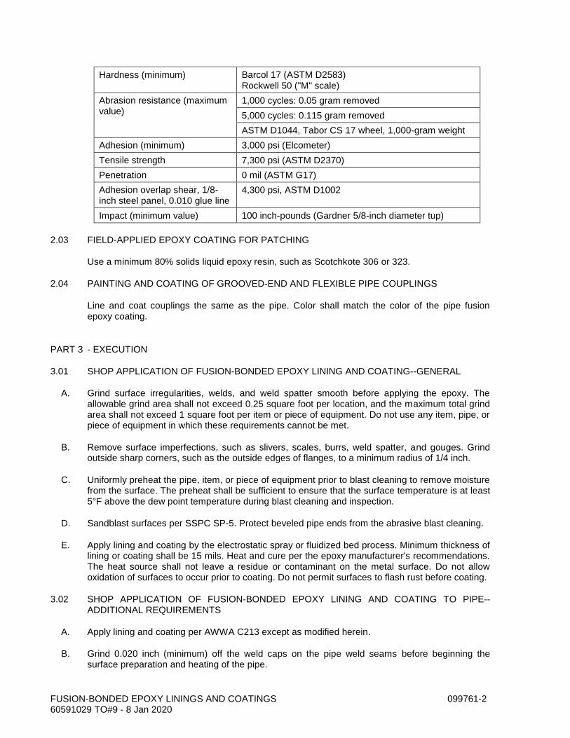
FUSION-BONDED EPOXY LININGS AND COATINGS 099761-2 60591029 TO#9 - 8 Jan 2020
Hardness (minimum) Barcol 17 (ASTM D2583) Rockwell 50 ("M" scale)
Abrasion resistance (maximum value)
1,000 cycles: 0.05 gram removed
5,000 cycles: 0.115 gram removed
ASTM D1044, Tabor CS 17 wheel, 1,000-gram weight
Adhesion (minimum) 3,000 psi (Elcometer)
Tensile strength 7,300 psi (ASTM D2370)
Penetration 0 mil (ASTM G17)
Adhesion overlap shear, 1/8-inch steel panel, 0.010 glue line
4,300 psi, ASTM D1002
Impact (minimum value) 100 inch-pounds (Gardner 5/8-inch diameter tup)
2.03 FIELD-APPLIED EPOXY COATING FOR PATCHING
Use a minimum 80% solids liquid epoxy resin, such as Scotchkote 306 or 323.
2.04 PAINTING AND COATING OF GROOVED-END AND FLEXIBLE PIPE COUPLINGS
Line and coat couplings the same as the pipe. Color shall match the color of the pipe fusion epoxy coating.
PART 3 - EXECUTION
3.01 SHOP APPLICATION OF FUSION-BONDED EPOXY LINING AND COATING--GENERAL
A. Grind surface irregularities, welds, and weld spatter smooth before applying the epoxy. The allowable grind area shall not exceed 0.25 square foot per location, and the maximum total grind area shall not exceed 1 square foot per item or piece of equipment. Do not use any item, pipe, or piece of equipment in which these requirements cannot be met.
B. Remove surface imperfections, such as slivers, scales, burrs, weld spatter, and gouges. Grind outside sharp corners, such as the outside edges of flanges, to a minimum radius of 1/4 inch.
C. Uniformly preheat the pipe, item, or piece of equipment prior to blast cleaning to remove moisture from the surface. The preheat shall be sufficient to ensure that the surface temperature is at least 5°F above the dew point temperature during blast cleaning and inspection.
D. Sandblast surfaces per SSPC SP-5. Protect beveled pipe ends from the abrasive blast cleaning.
E. Apply lining and coating by the electrostatic spray or fluidized bed process. Minimum thickness of lining or coating shall be 15 mils. Heat and cure per the epoxy manufacturer's recommendations. The heat source shall not leave a residue or contaminant on the metal surface. Do not allow oxidation of surfaces to occur prior to coating. Do not permit surfaces to flash rust before coating.
3.02 SHOP APPLICATION OF FUSION-BONDED EPOXY LINING AND COATING TO PIPE--ADDITIONAL REQUIREMENTS
A. Apply lining and coating per AWWA C213 except as modified herein.
B. Grind 0.020 inch (minimum) off the weld caps on the pipe weld seams before beginning the surface preparation and heating of the pipe.

FUSION-BONDED EPOXY LININGS AND COATINGS 099761-3 60591029 TO#9 - 8 Jan 2020
3.03 SHOP APPLICATION OF FUSION-BONDED EPOXY LINING AND COATING TO JOINT AREAS OF DUCTILE-IRON AND CAST-IRON FITTINGS--ADDITIONAL REQUIREMENTS
Limit the protective coating thickness in the joints of ductile-iron and cast-iron fittings to maintain a leak-proof joint. However, the coating thickness in the joint area shall not be less than 4 mils.
3.04 QUALITY OF LINING AND COATING APPLICATIONS
The cured lining or coating shall be smooth and glossy, with no graininess or roughness. The lining or coating shall have no blisters, cracks, bubbles, underfilm voids, mechanical damage, discontinuities, or holidays.
3.05 FACTORY TESTING OF COATING--GENERAL
A. Test linings and coatings with a low-voltage wet sponge holiday detector. Test pipe linings and coatings per AWWA C213, Section 5.3.3. If the number of holidays or pinholes is fewer than one per 20 square feet of coating surface, repair the holidays and pinholes by applying the coating manufacturer's recommended patching compound to each holiday or pinhole and retest. If the number of pinholes and holidays exceeds one per 20 square feet of coating surface, remove the entire lining or coating and recoat the item or pipe.
B. Measure the coating thickness at three locations on each item or piece of equipment or pipe section using a coating thickness gauge calibrated at least once per eight-hour shift. Record each measured thickness value. Where individual measured thickness values are less than the specified minimum thickness, measure the coating thickness at three additional points around the defective area. The average of these measurements shall exceed the specified minimum thickness value, and no individual thickness value shall be more than 2 mils below or 3 mils above the specified minimum value. If a section of the pipe, item, or piece of equipment does not meet these criteria, remove the entire lining or coating and recoat the entire item or piece of equipment.
3.06 FACTORY INSPECTION OF LINING AND COATING OF PIPE--ADDITIONAL REQUIREMENTS
Check for coating defects on the weld seam centerlines. There shall be no porous blisters, craters, or pimples lying along the peak of the weld crown.
3.07 SHIPPING, STORAGE, AND HANDLING
A. When loading piping, fittings, couplings, or other coated items for shipment to the project site, use spacers and other protective devices to separate pipes or other coated items to prevent damaging the coated surfaces during transit and unloading. If wood spacers are used, remove wood splinters and particles from the coated surfaces after separation. Use padded chains or ribbon binders to secure the loaded pipe or other coated items and minimize damage.
B. Do not load or unload pipe, fittings, couplings, or other coated items by inserting forklift tines or lifting chains inside the pipe or item. Use nonmetallic slings, padded chains, or padded forklift tines to lift pipe or other coated items.
C. Cover piping or other coated items 100% with protective coverings or tarpaulins to prevent deposition of road salts, fuel residue, and other contaminants in transit.
D. Provide stulls, braces, and supports for piping during shipping and storage such that out-of-roundness or deflection does not exceed 0.5% of the pipe diameter.

FUSION-BONDED EPOXY LININGS AND COATINGS 099761-4 60591029 TO#9 - 8 Jan 2020
E. Handle piping and other coated items with care during the unloading, installation, and erection operations to minimize damage. Do not place or store pipe or other coated items on the ground or on top of other work unless ground or work is covered with a protective covering or tarpaulin. Place pipe or other coated items above the ground upon platforms, skids, or other supports.
F. Store piping or other coated items at the site on pallets to prevent direct contact with ground or floor. Cover pipe or coated items during storage with protective coverings or tarpaulins to prevent deposition of rainwater, salt air, dirt, dust, and other contaminants.
G. Do not allow piping or other coated items to contact metal, concrete, or other surfaces during storage, handling, or installation and erection at the site that could damage or scratch the coating.
3.08 FIELD REPAIRS
Patch scratches and damaged areas incurred while installing fusion-bonded epoxy coated items with a two-component, 80% solids (minimum), liquid epoxy resin. Wire brush or sandblast the damaged areas per SSPC SP-10. Lightly abrade or sandblast the coating or lining on the sides of the damaged area before applying the liquid epoxy coating. Apply an epoxy coating to defective linings and coatings to areas smaller than 20 square inches. Patched areas shall overlap the parent or base coating a minimum of 0.5 inch. If a defective area exceeds 20 square inches, remove the entire lining and coating and recoat the entire item or piece of equipment. Apply the liquid epoxy coating to a minimum dry-film thickness of 15 mils.
END OF SECTION
PUMP CONTROL SYSTEMS 221329-1 60591029 TO#9 - 8 Jan 2020
SECTION 221329 PUMP CONTROL SYSTEMS
PART 1 GENERAL
1.01 SCOPE
A. Provide complete Pump Control Systems for wastewater pump stations by monitoring liquid level in wet well using pressure sensing-type level input. For integration with the present Turlock system, the controller shall be Mercoid MPC-JR-RC unit. The controller along with all electric power, level controls, and power converters shall be located inside the Pump Control Panel.
B. The Pump Control Panel with all associated appurtenances constitutes the Pump Controls System.
C. The major Pump Control Panel components include: well level controller, Variable Frequency Drives (for 1ø stations, VFD will be used to convert to 3ø), motor starters, protective relays, intrinsically safe relay, control relays, pushbuttons, 12-Volt DC power supply/battery charger, battery, control power transformer, terminals, circuit breakers, fuses, surge protective device, enclosure, wiring, wire-ways, and all other necessary appurtenances.
D. Major components required in the complete pump control system are specified herein. Other components are not directly specified but are nonetheless required and shall be provided by the pump control panel fabricator as shown on the pump control panel drawings. The panel fabricator shall provide a completely operational, prewired, pretested pump control system.
E. The Pump Control System supplier shall purchase and install new, good quality materials to provide a completely functioning UL 698 or 698A listed system, as intended. Any requirements in the specification or drawings that could possibly jeopardize the panel’s UL listing shall be substituted by the Pump Control Panel supplier/fabricator with UL acceptable products. The Contractor is responsible to immediately notify the Engineer of any and all changes to the materials list as a result of this requirement. Detailed justification shall be provided for each substituted part. Owner and Engineer retain the right to reject or require other components be used per specifications at no additional cost to Owner. Schedule delays caused by review of substituted parts in the Pump Control Panel are the responsibility of the Contractor.
1.02 SUBMITTALS
A. Section 01300 - Submittals.
B. Shop Drawings: Comply with NEMA ICS 1 and indicate control panel layouts, wiring connections and diagrams, dimensions, and support points. The layout shall exactly match Owner’ control panel drawing. Only Owner-approved, justified changes are allowed and written approval is required prior to deviation from Owner’ control panel drawings. The Engineer will require 21 calendar days to review design deviations. Schedule for submittal review is the Contractor’s responsibility.
C. The Pump Controls System supplier/fabricator shall provide to Owner and the Engineer a completely “As-Built” set of drawings in ACAD format and in PDF format. Complete materials list, with manufacturer and part numbers shall be included. Drawings and Materials Lists shall be provided on read/write CDs, three (3) copies are required.
D. Product Data: Submit catalog data for each component showing electrical characteristics, physical dimensions and connection requirements. Product Data for components may be provided as PDF catalog cut-sheets on CD, or neatly bound and tabbed in 3-ring binders with

PUMP CONTROL SYSTEMS 221329-2 60591029 TO#9 - 8 Jan 2020
table of contents. All component selections shall be highlighted or otherwise outlined to indicate to the Engineer and Owner which components are selected. If proper marking has not been done, the submittal will be returned to the Contractor without comments and will be unequivocally rejected.
E. Materials used shall be as per the attached material lists at the back of this specification section. “Or-equal” substituted components shall be noted in the panel fabricator’s submittal with complete information required in paragraph C above. Only pre-approved substitute parts will be allowed. Any parts substituted that are unapproved will result in panel rejection at the Contractors’ expense. However, the Pump Controls System provider is encouraged to submit better-performing products and/or improved design ideas for review at the proper time.
PART 2 PRODUCTS
2.01 PUMP CONTROL SYSTEM OVERVIEW
A. System Requirements: The duplex pump controllers to be provided for this project shall be the MPC Junior microprocessor based pump controller, no exception. Standardization of pump control panel design and interchangeability of parts necessitate this requirement. The following major equipment items compatible components shall be used:
1. Level Controller: MPC-JR-RC.
2. Level Sensor/Transmitter: Pressure type, 4-20mA output.
B. The Pump Control Panels shall be provided with a main circuit breaker with handle operator. All circuit breaker handle operators shall properly fit respective circuit breakers and shall not impede swing-out door operation. Improperly fitted circuit breaker extension handles, or any problems caused by the circuit breaker handles shall be repaired by the Contractor at his expense and at no additional cost to Owner.
C. Motor protection:
1. The pump controller shall be used to provide advanced motor protection and data analysis of the system performance as well as signal a SCADA system. The SCADA system is existing.
2. Individual motor starters shall be supplied with a properly sized, line-side, thermal magnetic-type circuit breaker to provide short circuit and ground fault overcurrent protection and act as a disconnecting means. Refer to paragraph 2.8, Motor Starters, below. In pump control panel, auxiliary contact on circuit breaker disconnecting means generates alarm to the pump controller when in the OFF position. Each motor shall be provided with an isolation contactor sized per motor nameplate FLA, meeting requirements of NEC 430.32 and these specifications. Reset Push Buttons shall be located on the on the inner door and will reset the overload relay.
3. Each pump motor shall be wired to an electrode relay providing high probe potential for the leak detection system built into the oil filled motor shaft housing. The electrodes will activate if moisture content in the oil sealed area reaches abnormal levels. Electrode activation shall open the control circuit to the pump motor starter preventing possible damage to the pump motor from water ingestion. Pump will be placed out of service until maintenance is performed on the unit and control system reset.
PUMP CONTROL SYSTEMS 221329-3 60591029 TO#9 - 8 Jan 2020
D. Enclosure: All required equipment shall be installed inside a stainless steel enclosure equipped with a subpanel and interior swing open dead front door. The Enclosure is located in a non-hazardous but corrosive location, outdoors exposed to weather. Circuits originating from enclosure extend into an NFPA-820 and NEC rated C1 D2 Group D hazardous (classified) area. Separate all wiring for intrinsically safe circuitry in accordance with NEC Article 504.
E. System Voltage Protection: Surge Protective Device (SPD) shall be provided, prewired inside the enclosure. The UL 1449 SPD shall provide 4-mode, line- voltage surge protection for the control panel incoming power supply. The SPD shall have a minimum surge rating of 200kA/phase, with each phase having its own status indicator. Surge current modes are Line to Neutral, Line to Ground, Neutral to Ground, and Line to Line, and each mode shall have a minimum of 100kA/phase protection. The SPD shall be provided with a line-side, manual disconnecting switch inside the panel to simultaneously disconnect all ungrounded conductors for maintenance. Lead lengths shall be as short as possible
F. Remote Alarm Reporting - The Pump Control Panel shall report alarms remotely via the SCADA system. Alarms shall be reported through SCADA for any of the following reasons:
1. High water level in wet well.
2. The moisture detection system indicates moisture in the oil chamber between the motor seals.
3. The motor winding temp switches indicate high motor temperature caused by improper motor cooling or motor overload.
4. Overload protective devices in motor controls circuit indicate motor overload.
5. Electrical failure detected by the power failure control relay, or by the phase monitor.
6. VFD failure.
7. Motor branch circuit breaker disconnecting device left in “off” position.
8. Other alarm events.
G. Wiring:
1. Control wire shall be MTW, 90 degree C, #14 AWG, stranded copper. Signal wiring may be #16 AWG.
2. All wiring should be neatly grouped in plastic wire trough except wiring from the backplate to the door shall be done in separate bundled harnesses.
3. All wires shall have a wraparound wire identification number as shown in the wiring diagram at both ends.
4. All components shall be identified with the same number as shown in the control panel schematic drawings.
2.02 CONTROL SWITCHES AND STATIONS
A. Manufacturers:
1. ABB.

PUMP CONTROL SYSTEMS 221329-4 60591029 TO#9 - 8 Jan 2020
2. Siemens
3. Eaton/Cutler-Hammer.
4. Square D.
5. Substitutions: Permitted if approved by Owner
B. Product Description: NEMA ICS 5, heavy-duty, corrosion resistant devices.
C. Contacts: Form C, or as required by control panel drawings.
D. Contact Ratings: Class A600.
E. Pushbutton Operator: Non-illuminated, momentary contact, flush type. Use pushbuttons listed as suitable for outdoors, weather-exposed applications.
2.03 MAGNETIC CONTROL RELAYS
A. Manufacturers:
1. ABB.
2. Siemens
3. Eaton/Cutler-Hammer.
4. Square D.
5. GE.
6. Substitutions: Permitted if approved by Owner
B. Product Description: NEMA ICS 5, Class A300 magnetic control relay. Relays shall have industry standard wiring and pin arrangements. Control relay coils shall be equipped with appropriate voltage-transient protection.
C. Contacts: Form C, or as selected by panel fabricator.
D. Contact Ratings: Class A150, minimum.
E. Coil Voltage: 120V, 60 Hz, AC; or 12 Volts DC, or as required on drawings.
F. Enclosure: NEMA ICS 6, Type to meet conditions of installation.
2.04 SOLID-STATE CONTROL RELAYS
A. Manufacturers:
1. ABB.
2. Siemens
3. Eaton/Cutler-Hammer.

PUMP CONTROL SYSTEMS 221329-5 60591029 TO#9 - 8 Jan 2020
4. Square D.
5. GE.
6. Substitutions: Permitted if approved by Owner
B. Product Description: NEMA ICS 5, solid-state electronic relay.
C. Contacts: Form C, or as selected by panel fabricator.
D. Contact Ratings: Class A150, minimum.
E. Coil Voltage: 120V, 60 Hz, AC, or 12 Volts DC, or as required on drawings.
F. Listing: UL Listed.
2.05 TIME DELAY RELAYS
A. Manufacturers:
1. Diversified electronics.
2. Artisan.
3. Siemens.
4. Eaton/Cutler-Hammer.
5. Square D.
6. Idec.
7. Substitutions: Permitted if approved by Owner.
B. Product Description: NEMA ICS 5, solid state, sealed switch timing relay. Unit is an initiate switch controlled, delay-on-break timer operating a set of contacts. Select optional timer settings as indicated on drawings.
C. Contacts: NEMA B600, 600VAC, 5 Amps.
D. Coil Voltage: 120 Volts, 60 Hz AC, or 12 Volts DC, as required on drawings.
E. Listing: UL Listed.
2.06 LEVEL TRANSMITTER
A. Manufacturers:
1. Mercoid
2. Substitutions: Permitted if approved by Owner.
B. Level transmitter shall be 0 to 10.0 psi, bird cage submersible level transmitter, with 4 to 20 mA output to continuously indicated depth of water above probe. Power to transmitter will be 13 to 30V DC. Transmitter wetted materials shall be 316 stainless steel, 316L SS, and Buna-N
PUMP CONTROL SYSTEMS 221329-6 60591029 TO#9 - 8 Jan 2020
gasketed. Accuracy shall be +/- 0.25% of full scale. Transmitter shall be Mercoid, Model No.PBLT2-10-40, or approved equal.
C. Mounting Kit: provide and install matching integral cleaning and mounting bracket with all appurtenances. Hardware shall be stainless steel.
2.07 LEVEL SWITCHES
A. Manufacturer:
1. Anchor Scientific
2. Substitutions: Permitted if approved by Owner.
B. Level switches shall be provided for each lift station, for Low-Low and High-High alarms and control. Level switch shall be mercury free, suspended cable type, suitable for wastewater sump level control. Contacts shall be rated for 120V AC and 48V DC applications. Switches shall be provided with 40 foot cable. Switches shall be Anchor Scientific, Model No. GSI40NONC, or approved equal. Mounting Kit: provide and install mounting bracket with all appurtenances. Hardware shall be stainless steel.
2.08 VFD
A. Manufacturers:
1. Altavar
2. Substitutions: Permitted if approved by Owner.
B. VFD (Variable Frequency Drive) Required for single phase to three phase conversions, for pump stations #42 and 55, two VFDs required at each of two pump stations.
1. All programming/configuration devices, display units, and field control wiring terminals shall be accessible on the front of the control module. Exposure to control circuit boards or electrical power devices during routine adjustments is prohibited.
2. Digital indication shall provide status on the VFD, faults, and the motor.
3. VFD shall have factory preset operational features for normal conditions. Parameters shall be field adjustable through the digital keypad. Motor FLA, starting current limits, linear acceleration ramps, torque adjustments, torque limits, starting time, voltage boost for starting, braking selections, deceleration ramps, braking torque and overload class selections shall be included as field adjustable parameters, as a minimum.
4. Output relays shall include one (1) NO contact for fault indication, one (1) NO contact for indication that acceleration ramp is complete and current is below 130% of motor FLA, for end-of-start, and one (1) programmable NO contact.
5. Additional I/O shall be provided as required on the project design drawings as a minimum. Provide two assignable control inputs for the force to freewheel stop, external fault input, disable serial link control, external motor overload reset or general fault reset. Include two assignable logic-level signal outputs for motor thermal overload alarm, motor powered signal, motor overcurrent alarm, or motor underload alarm. Include one analog output for 4 to 20 milliamp indication of motor speed or motor current.

PUMP CONTROL SYSTEMS 221329-7 60591029 TO#9 - 8 Jan 2020
6. Protection – A microprocessor-based motor thermal protection system shall be included which continuously calculates the temperature-rise of the motor and VFD and provides a motor overload pre-alarm that indicates by relay contact or logic output that the motor windings have exceeded 130% of its rated temperature rise. This function shall be for alarm only. A motor overload fault will stop the motor if the windings have exceeded 140% of temperature-rise. The VFD shall provide line and motor phase loss, phase reversal, underload, stall, and jam protection. The integral protective features shall be active even when the shorting contactor is used to bypass the SCRs during steady state operation.
7. Communications – To directly connect the VFD to Modbus, the VFD shall have to include a serial link. The VFD shall be able to be connected to Ethernet and other networks, with connection to the communication bus as an option. The communication shall be able to provide access to the control, to the adjustment and to the supervision of the VFD.
8. Cabinets containing a VFD will require a stainless steel air conditioning unit.
2.09 CONTROL POWER TRANSFORMER
A. Manufacturers:
1. ABB.
2. Siemens
3. Eaton/Cutler-Hammer.
4. Square D.
5. GE.
6. Substitutions: Permitted if approved by Owner
B. Product Description: NEMA ST 1, machine tool transformer with isolated secondary winding, UL listed.
C. Power Rating: 500 VA, or less to reduce heat load.
D. Voltage Rating: 240 Volts primary; 120 Volts secondary.
2.10 CONTROL PANEL ENCLOSURES
A. Manufacturers:
1. Saginaw.
2. B-Line.
3. Hoffman. – Design basis Enclosure and Air Conditioning unit.
4. EMF.
5. Substitutions: per Section 01300.
B. Product Description: Cabinet conforming to NEMA Type 3R, steel, powder coated enamel, white interior. The NEMA rating includes the installation of the Air Conditioner unit and the 3-point, 90
PUMP CONTROL SYSTEMS 221329-8 60591029 TO#9 - 8 Jan 2020
degree turn lockable latch kits that are required on this panel. Panel shall have a hinged blank outer door, hinged interior door to provide mounting surface for controller displays, labels, and other required components, and panel backplane.
C. Pump Control Panel Minimum Size: Pump control panel shall be wall mounted, with the panel firmly secured to supports. The minimum allowed enclosure size shall be 36x36x12 (inches).
D. Box Size: as required to meet project requirements. Ensure adequate wiring space is provided, and thermal/air flow needs of various components are considered in sizing of enclosure. VFD usage will require a stainless steel air conditioner.
E. Fronts: steel, fully gasketed, dead-front, surface mounted type with 3-point, quarter-turn latching, lockable door handle with concealed hinge. Hinges shall be completely rust-free under all circumstances. Enclosures, hinges or hardware that rusts, including “surface” rust where pitting is evident, shall cause the entire panel be replaced and any and all associated repair work and materials shall be at the Contractors’ expense and at no additional costs to Owner. Finish: manufacturer’s standard.
F. Knockouts: performed by field Contractor.
G. Furnish grounded metallic or other acceptable barriers to form separate compartments for wiring of different systems and voltages. Isolate Intrinsically Safe equipment per NEC Art. 504.
2.11 TERMINAL BLOCKS
A. Manufacturers:
1. ABB.
2. Cooper.
3. Eaton/Cutler-Hammer.
4. Square D.
5. GE.
6. Substitutions: Permitted with Owner approval
B. Product Description: NEMA ICS 4, terminal blocks.
C. Power Terminals: Unit construction type with closed back and tubular pressure screw connectors, rated 600 Volts. Suitable for use with copper wire.
D. Signal and Control Terminals: Modular construction type, suitable for channel mounting, with tubular pressure screw connectors, rated 600 Volts. Suitable for use with copper wire.
E. Include ground bus terminal block, with each connector bonded to enclosure.
F. Terminals shall be properly secured to sub-panel or din rails. If conductors are causing terminals to become stressed by over tension, or improper bending space or any other reasons causing the terminals to bend, deform, or become over-burdened, the Contractor shall make repairs at his expense, at no additional cost to Owner.

PUMP CONTROL SYSTEMS 221329-9 60591029 TO#9 - 8 Jan 2020
2.12 PLASTIC RACEWAY
A. Manufacturers:
1. ABB.
2. Panduit.
3. Hoffman.
4. Thomas&Betts.
5. Substitutions: Permitted as required by panel fabricator.
B. Product Description: Plastic channel with hinged or snap-on cover.
C. SCADA Communications Equipment Required Equipment: None, Owner will provide or reconnect radio equipment to connect to the Contractor-provided Mercoid MPC-JR-RC controller in each pump station.
D. System Description:
1. All control signals, status signals, alarm and or process variable data generated by the pump controls shall be transmitted and received between the central location and the remote site via the SCADA radio communication system. Ensure that Radio Communication of Charleston performs a path study between remote pump station locations and repeaters or master stations as required.
2. The Pump Controller is a Mercoid Junior with DNP3, flow calculation, logic engine, and I/O. The controller provides signal input to the radio. Power input to the radio comes from the 12 VDC power supply unit that is in the Pump Control Panel described in 2.1, G, above.
3. Any additional components, testing, or required equipment for a completely operational SCADA radio communications shall be provided by the Owner.
PART 3 EXECUTION
3.01 EXISTING WORK
A. Where necessary, disconnect and remove abandoned controls and relays remaining at job site. Maintain station electrical service and control at all times except for switchover to new controls. Coordinate with Owner prior to switchover.
B. Where existing equipment is present, dispose of equipment / materials as directed by Owner.
C. Owner may elect to salvage certain equipment. If Owner decides to salvage any equipment, wiring or materials, it shall be returned to Owner cleaned and in an undamaged condition. Coordinate with Owner for a location to store or stage salvaged materials.
3.02 INSTALLATION
A. Install the assembled and pre-tested pump control panel on the electrical equipment rack, or bolt down to the concrete pad if free-standing, as shown on the project design drawings.
PUMP CONTROL SYSTEMS 221329-10 60591029 TO#9 - 8 Jan 2020
B. Install enclosures and boxes plumb.
C. Install level transmitter, level switches, and make all electrical wiring interconnections as required by the equipment, as provided and as indicated on the Contract Drawings, and as otherwise required for a completely functional control system.
D. Install engraved plastic nameplates.
E. Ground and bond control panels, raceway, and Intrinsically Safe barriers and relays.
F. Conduits entering the control panel from the wet well must be sealed in accordance with NEC Article 500, Class 1, Group D Specifications Separate wiring for intrinsically safe circuits for the level probe per NEC 504.
G. Clean the enclosure completely, vacuum out any wire strippings, clippings or metallic filings that may be found. Use manufacturer recommended cleaning agents. Improperly cleaned cabinets are cause for rejection of construction work.
H. Digital I/O will be located in accordance to the vendor standard and the Owner standard input diagram for all pump station configurations.
I. Pump Station I/O List

PUMP CONTROL SYSTEMS 221329-11 60591029 TO#9 - 8 Jan 2020
INPUT NAME* INPUT NAME TERMINAL
Pump 1 Thermal Flygt Seal DI 12
ABS Seal DI 13
Thermal Overload Pump 1 TOL DI 14
Pump 2 Thermal Flygt Seal DI 15
ABS Seal DI 16
Thermal Overload Pump 2 TOL DI 17
High-High Level Alarm DI 18
Low-Low Level Alarm DI 19
DI 20
Wetwell Level Level Signal AI1
Flowmeter Rate AI2
Main Breaker Tripped/Off DI 0
Generator Run DI 1
Generator Fail DI 2
Pump 1 VFD/SSS Fault DI 3
Pump 2 VFD/SSS Fault DI 4
DI 5
Utility Power Fail DI 6
DI 7
DI 8
DI 9
Flowmeter DI 10
Rain Gauge DI 11
* - SPARE if not designated.
END OF SECTION

PUMP CONTROL SYSTEMS 221329-12 60591029 TO#9 - 8 Jan 2020
THIS PAGE INTENTIONALLY LEFT BLANK

GENERAL ELECTRICAL REQUIREMENTS 260500-1 60591029 TO#9 - 8 Jan 2020
SECTION 260500 GENERAL ELECTRICAL REQUIREMENTS
PART 1 - GENERAL
1.01 DESCRIPTION
This section includes materials, installation, and testing of the electrical system.
1.02 SUBMITTALS
A. Submit manufacturer cut sheets for all materials and complete shop drawings in accordance with the Special Provisions.
B. In submitted catalog cuts, cross out items shown that are not pertinent to this project. Where catalog cuts list manufacturer’s standard options, cross out those options not intended to be provided and clearly highlight those options that are to be provided.
1.03 REGULATORY AGENCIES AND STANDARDS
A. See Special Provisions.
B. Electrical work shall comply with the NEC as amended by the CEC and local city code where applicable.
1.04 QUALITY CONTROL
Materials, appliances, equipment, and devices shall conform to the applicable UL standards. The label of, or listing by, UL is required for all electrical equipment.
1.05 POWER FOR CONSTRUCTION
Provide for or purchase power for construction in accordance with Section 015100.
1.06 LOCATIONS
A. General: Use equipment, materials, and wiring methods suitable for the types of locations in which they are located as defined below.
B. Definitions of Types of Locations:
1. Dry Locations: Indoor areas which do not fall within the definitions below for wet, damp, hazardous, or corrosive locations and which are not otherwise designated in the drawings.
2. Wet Locations: Locations exposed to the weather, whether under a roof or not, unless otherwise designated in the drawings.
3. Corrosive Locations: Areas identified in drawings.
GENERAL ELECTRICAL REQUIREMENTS 260500-2 60591029 TO#9 - 8 Jan 2020
PART 2 - MATERIALS
2.01 GENERAL
A. Similar materials and equipment shall be the product of a single manufacturer.
B. Provide only products which are new, undamaged, and in the original cartons or containers.
C. Materials and equipment shall be the standard products of manufacturers regularly engaged in the production of such material and shall be the manufacturer's current design.
D. Materials and equipment shall be suitable for storage, installation, and operation at an ambient temperature of 0°C to 40°C except where more stringent conditions are stated in individual equipment specifications.
E. Electrical equipment and panels shall be factory finished with manufacturer's standard primer and enamel topcoats, unless stated otherwise in the individual equipment specifications. Provide 1 pint of the equipment manufacturer's touchup paint per 500 square feet of painted surface for repair of damaged enamel topcoats.
PART 3 - EXECUTION
3.01 INSTALLATION
A. The drawings indicate connections for typical equipment only. If the equipment furnished is different from what is shown, provide the modifications necessary for a safe and properly operating installation in accordance with the equipment manufacturer's recommendations.
B. The drawings diagrammatically indicate the desired location and arrangement of outlets, conduit runs, equipment, and other items. Field determine exact location based on physical size and arrangement of equipment, finished elevations, and obstructions.
C. Work or equipment not indicated or specified which is necessary for the complete and proper operation of the electrical systems shall be accomplished without additional cost to the Owner.
D. Seal weathertight equipment or components exposed to the weather.
E. Protect equipment outlets and conduit openings with factory-made plugs or caps whenever work is not in progress at that point.
3.02 REMOVAL OF MATERIALS AND EQUIPMENT
Unless otherwise noted, remove existing electrical materials and equipment from areas indicated for demolition. Remove materials no longer used. Remove existing unused wires.
END OF SECTION
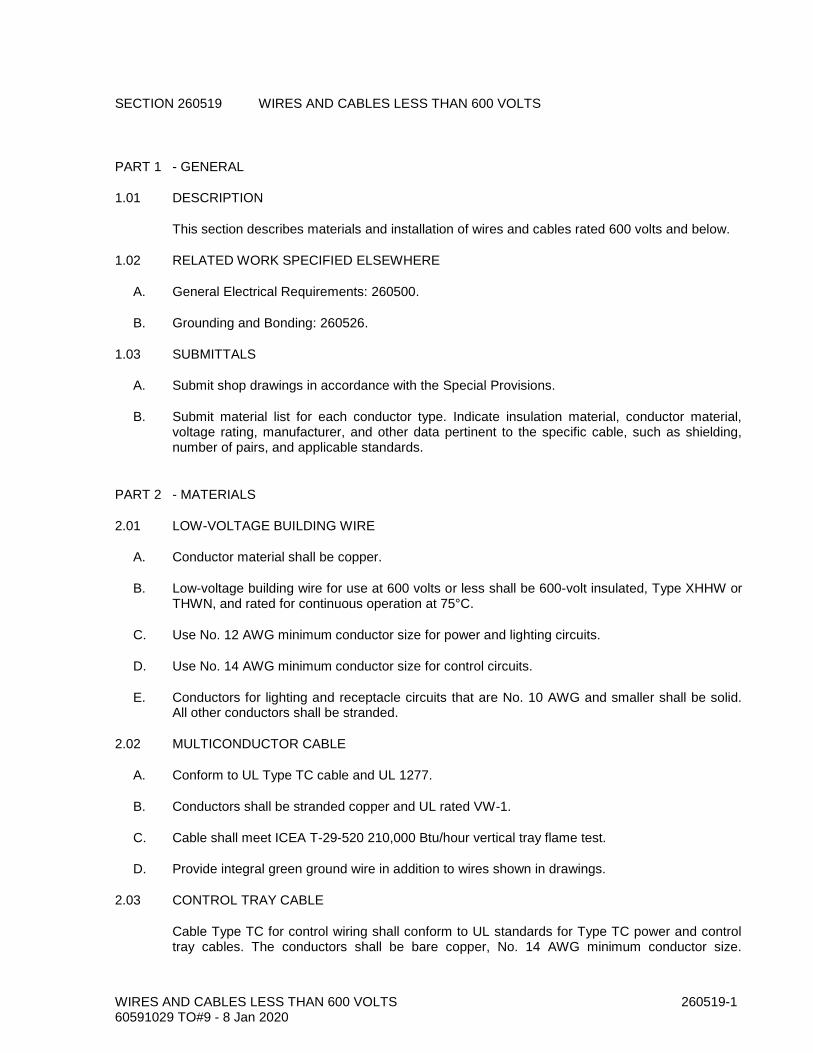
WIRES AND CABLES LESS THAN 600 VOLTS 260519-1 60591029 TO#9 - 8 Jan 2020
SECTION 260519 WIRES AND CABLES LESS THAN 600 VOLTS
PART 1 - GENERAL
1.01 DESCRIPTION
This section describes materials and installation of wires and cables rated 600 volts and below.
1.02 RELATED WORK SPECIFIED ELSEWHERE
A. General Electrical Requirements: 260500.
B. Grounding and Bonding: 260526.
1.03 SUBMITTALS
A. Submit shop drawings in accordance with the Special Provisions.
B. Submit material list for each conductor type. Indicate insulation material, conductor material, voltage rating, manufacturer, and other data pertinent to the specific cable, such as shielding, number of pairs, and applicable standards.
PART 2 - MATERIALS
2.01 LOW-VOLTAGE BUILDING WIRE
A. Conductor material shall be copper.
B. Low-voltage building wire for use at 600 volts or less shall be 600-volt insulated, Type XHHW or THWN, and rated for continuous operation at 75°C.
C. Use No. 12 AWG minimum conductor size for power and lighting circuits.
D. Use No. 14 AWG minimum conductor size for control circuits.
E. Conductors for lighting and receptacle circuits that are No. 10 AWG and smaller shall be solid. All other conductors shall be stranded.
2.02 MULTICONDUCTOR CABLE
A. Conform to UL Type TC cable and UL 1277.
B. Conductors shall be stranded copper and UL rated VW-1.
C. Cable shall meet ICEA T-29-520 210,000 Btu/hour vertical tray flame test.
D. Provide integral green ground wire in addition to wires shown in drawings.
2.03 CONTROL TRAY CABLE
Cable Type TC for control wiring shall conform to UL standards for Type TC power and control tray cables. The conductors shall be bare copper, No. 14 AWG minimum conductor size.
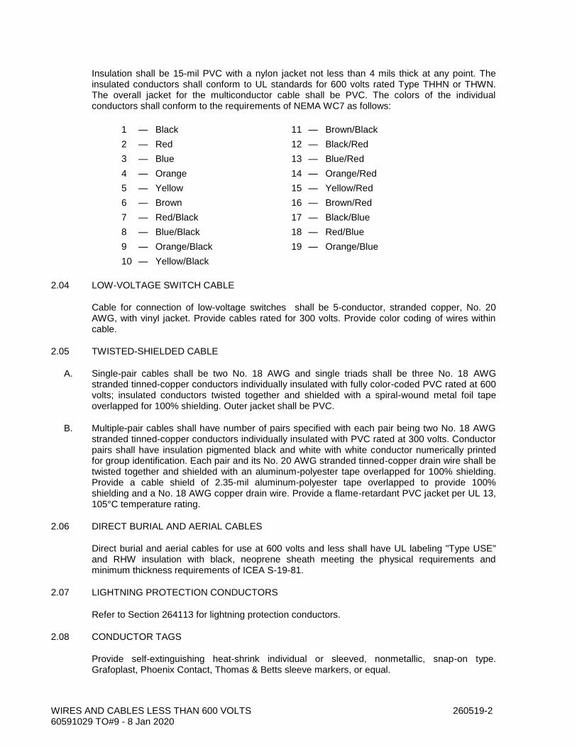
WIRES AND CABLES LESS THAN 600 VOLTS 260519-2 60591029 TO#9 - 8 Jan 2020
Insulation shall be 15-mil PVC with a nylon jacket not less than 4 mils thick at any point. The insulated conductors shall conform to UL standards for 600 volts rated Type THHN or THWN. The overall jacket for the multiconductor cable shall be PVC. The colors of the individual conductors shall conform to the requirements of NEMA WC7 as follows:
1 — Black 11 — Brown/Black
2 — Red 12 — Black/Red
3 — Blue 13 — Blue/Red
4 — Orange 14 — Orange/Red
5 — Yellow 15 — Yellow/Red
6 — Brown 16 — Brown/Red
7 — Red/Black 17 — Black/Blue
8 — Blue/Black 18 — Red/Blue
9 — Orange/Black 19 — Orange/Blue
10 — Yellow/Black
2.04 LOW-VOLTAGE SWITCH CABLE
Cable for connection of low-voltage switches shall be 5-conductor, stranded copper, No. 20 AWG, with vinyl jacket. Provide cables rated for 300 volts. Provide color coding of wires within cable.
2.05 TWISTED-SHIELDED CABLE
A. Single-pair cables shall be two No. 18 AWG and single triads shall be three No. 18 AWG stranded tinned-copper conductors individually insulated with fully color-coded PVC rated at 600 volts; insulated conductors twisted together and shielded with a spiral-wound metal foil tape overlapped for 100% shielding. Outer jacket shall be PVC.
B. Multiple-pair cables shall have number of pairs specified with each pair being two No. 18 AWG stranded tinned-copper conductors individually insulated with PVC rated at 300 volts. Conductor pairs shall have insulation pigmented black and white with white conductor numerically printed for group identification. Each pair and its No. 20 AWG stranded tinned-copper drain wire shall be twisted together and shielded with an aluminum-polyester tape overlapped for 100% shielding. Provide a cable shield of 2.35-mil aluminum-polyester tape overlapped to provide 100% shielding and a No. 18 AWG copper drain wire. Provide a flame-retardant PVC jacket per UL 13, 105°C temperature rating.
2.06 DIRECT BURIAL AND AERIAL CABLES
Direct burial and aerial cables for use at 600 volts and less shall have UL labeling "Type USE" and RHW insulation with black, neoprene sheath meeting the physical requirements and minimum thickness requirements of ICEA S-19-81.
2.07 LIGHTNING PROTECTION CONDUCTORS
Refer to Section 264113 for lightning protection conductors.
2.08 CONDUCTOR TAGS
Provide self-extinguishing heat-shrink individual or sleeved, nonmetallic, snap-on type. Grafoplast, Phoenix Contact, Thomas & Betts sleeve markers, or equal.

WIRES AND CABLES LESS THAN 600 VOLTS 260519-3 60591029 TO#9 - 8 Jan 2020
Provide adhesive-type markers. Brady, Thomas & Betts, or equal.
2.09 PLASTIC ADHESIVES
Plastic adhesives for color coding shall be 7-mil minimum thick, flame-retardant, weather-resistant tape, resisting abrasion, UL rays, moisture, alkalies, solvents, and acids. Adhesives shall meet the requirements of UL 510 and CSA C22.2.
PART 3 - EXECUTION
3.01 LOW-VOLTAGE BUILDING WIRE INSTALLATION
A. Install wiring and cable in conduit and terminate unless otherwise noted.
B. To reduce pulling tension in long runs, coat cables with pulling compound recommended by the cable manufacturer before being pulled into conduits.
C. Remove debris and moisture from the conduits, boxes, and cabinets prior to cable installation.
D. Group conductors No. 1/0 and smaller in panelboards, cabinets, pull boxes, motor control centers, and switchboard wireways; tie with plastic ties; and fan out to terminals. Lace conductors No. 2/0 and larger with marline.
3.02 IDENTIFICATION
A. Color Coding of Low-Voltage Building Wire: Provide color coding throughout the entire network of feeders and circuits as follows:
Phase 240/120 Volts 208/120 Volts 240 Volts 480/277 Volts
Phase A Black Black Black Brown
Phase B Red Red Red Orange
Phase C --- Blue Blue Yellow
Neutral White White White Gray
Ground Green Green Green Green
B. Phase conductors No. 10 AWG and smaller and neutral/ground conductors No. 6 and smaller shall have factory color coding with solid color insulation. Do not use onsite coloring of ends of conductors or apply colored plastic adhesives in lieu of factory color coding. Larger conductors may have onsite application of colored plastic adhesives at ends of conductors and at each splice.
C. Control wires shall have colored insulation. Separate color codes for each wire shall be provided in each conduit that has up to seven wires. Conduits with more than seven wires shall have at least seven types of colored insulation.
D. Tagging of Conductors: Tag control wires and instrument cables in panels, pull boxes, wireways, and at control device. Tag control wires and instrument cables with same wire numbers as on the shop drawing submittals. Tag power wires in pull boxes and wireways where there is more than one circuit. Tag power conductors with motor control center or panelboard number and circuit numbers.
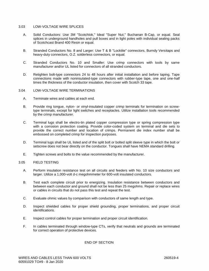
WIRES AND CABLES LESS THAN 600 VOLTS 260519-4 60591029 TO#9 - 8 Jan 2020
3.03 LOW-VOLTAGE WIRE SPLICES
A. Solid Conductors: Use 3M "Scotchlok," Ideal "Super Nut," Buchanan B-Cap, or equal. Seal splices in underground handholes and pull boxes and in light poles with individual sealing packs of Scotchcast Brand 400 Resin or equal.
B. Stranded Conductors No. 8 and Larger: Use T & B "Locktite" connectors, Burndy Versitaps and heavy-duty connectors, O.Z. solderless connectors, or equal.
C. Stranded Conductors No. 10 and Smaller: Use crimp connectors with tools by same manufacturer and/or UL listed for connectors of all stranded conductors.
D. Retighten bolt-type connectors 24 to 48 hours after initial installation and before taping. Tape connections made with noninsulated-type connectors with rubber-type tape, one and one-half times the thickness of the conductor insulation, then cover with Scotch 33 tape.
3.04 LOW-VOLTAGE WIRE TERMINATIONS
A. Terminate wires and cables at each end.
B. Provide ring tongue, nylon- or vinyl-insulated copper crimp terminals for termination on screw-type terminals, except for light switches and receptacles. Utilize installation tools recommended by the crimp manufacturer.
C. Terminal lugs shall be electro-tin plated copper compression type or spring compression type with a corrosion protection coating. Provide color-coded system on terminal and die sets to provide the correct number and location of crimps. Permanent die index number shall be embossed on completed crimp for inspection purposes.
D. Terminal lugs shall be UL listed and of the split bolt or bolted split sleeve type in which the bolt or setscrew does not bear directly on the conductor. Tongues shall have NEMA standard drilling.
E. Tighten screws and bolts to the value recommended by the manufacturer.
3.05 FIELD TESTING
A. Perform insulation resistance test on all circuits and feeders with No. 10 size conductors and larger. Utilize a 1,000-volt d-c megohmmeter for 600-volt insulated conductors.
B. Test each complete circuit prior to energizing. Insulation resistance between conductors and between each conductor and ground shall not be less than 25 megohms. Repair or replace wires or cables in circuits that do not pass this test and repeat the test.
C. Evaluate ohmic values by comparison with conductors of same length and type.
D. Inspect shielded cables for proper shield grounding, proper terminations, and proper circuit identifications.
E. Inspect control cables for proper termination and proper circuit identification.
F. In cables terminated through window-type CTs, verify that neutrals and grounds are terminated for correct operation of protective devices.
END OF SECTION

GROUNDING AND BONDING 260526-1 60591029 TO#9 - 8 Jan 2020
SECTION 260526 GROUNDING AND BONDING
PART 1 - GENERAL
1.01 DESCRIPTION
This section includes materials, testing, and installation of electrical grounding.
1.02 RELATED WORK SPECIFIED ELSEWHERE
A. General Electrical Requirements: 260500.
B. Wires and Cables Less Than 600 Volts: 260519.
1.03 SUBMITTALS
A. Submit shop drawings in accordance with the Special Provisions.
B. Submit material list for all grounding materials and equipment. Indicate size, material, and manufacturer.
C. Submit test results. Indicate overall resistance to ground and resistance of each electrode.
1.04 PERFORMANCE REQUIREMENTS
A. Grounding System Resistance:
1. Separately Derived Sources (as Defined by NEC 250) Grounding Electrode: 25 ohms.
2. Grounds Not Covered Above: 25 ohms.
PART 2 - MATERIALS
2.01 GROUND RODS
Ground rods shall be copper-clad steel, 3/4 inch in diameter, minimum 10 feet long, with hardened steel points.
2.02 CONNECTIONS
A. Ground Clamps: Clamps for connection of ground wire to ground rod shall be bronze.
B. Exothermic Connections: Provide Cadweld or equal.
2.03 CONDUCTORS
A. Equipment Ground: Conductors shall be low-voltage building-wire type as specified in Section 260519.
B. Bare Copper Conductors: Annealed bare copper, conforming to ASTM B3 and B8.
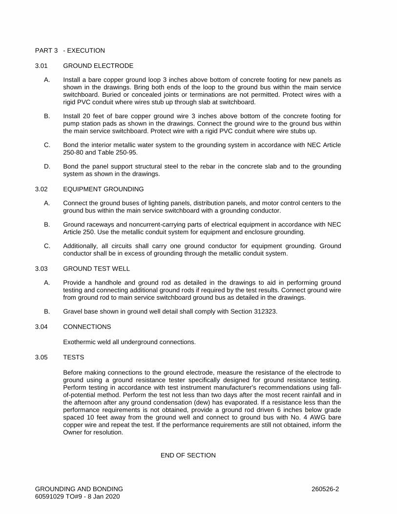
GROUNDING AND BONDING 260526-2 60591029 TO#9 - 8 Jan 2020
PART 3 - EXECUTION
3.01 GROUND ELECTRODE
A. Install a bare copper ground loop 3 inches above bottom of concrete footing for new panels as shown in the drawings. Bring both ends of the loop to the ground bus within the main service switchboard. Buried or concealed joints or terminations are not permitted. Protect wires with a rigid PVC conduit where wires stub up through slab at switchboard.
B. Install 20 feet of bare copper ground wire 3 inches above bottom of the concrete footing for pump station pads as shown in the drawings. Connect the ground wire to the ground bus within the main service switchboard. Protect wire with a rigid PVC conduit where wire stubs up.
C. Bond the interior metallic water system to the grounding system in accordance with NEC Article 250-80 and Table 250-95.
D. Bond the panel support structural steel to the rebar in the concrete slab and to the grounding system as shown in the drawings.
3.02 EQUIPMENT GROUNDING
A. Connect the ground buses of lighting panels, distribution panels, and motor control centers to the ground bus within the main service switchboard with a grounding conductor.
B. Ground raceways and noncurrent-carrying parts of electrical equipment in accordance with NEC Article 250. Use the metallic conduit system for equipment and enclosure grounding.
C. Additionally, all circuits shall carry one ground conductor for equipment grounding. Ground conductor shall be in excess of grounding through the metallic conduit system.
3.03 GROUND TEST WELL
A. Provide a handhole and ground rod as detailed in the drawings to aid in performing ground testing and connecting additional ground rods if required by the test results. Connect ground wire from ground rod to main service switchboard ground bus as detailed in the drawings.
B. Gravel base shown in ground well detail shall comply with Section 312323.
3.04 CONNECTIONS
Exothermic weld all underground connections.
3.05 TESTS
Before making connections to the ground electrode, measure the resistance of the electrode to ground using a ground resistance tester specifically designed for ground resistance testing. Perform testing in accordance with test instrument manufacturer's recommendations using fall-of-potential method. Perform the test not less than two days after the most recent rainfall and in the afternoon after any ground condensation (dew) has evaporated. If a resistance less than the performance requirements is not obtained, provide a ground rod driven 6 inches below grade spaced 10 feet away from the ground well and connect to ground bus with No. 4 AWG bare copper wire and repeat the test. If the performance requirements are still not obtained, inform the Owner for resolution.
END OF SECTION

CONDUITS, BOXES, AND FITTINGS 260534-1 60591029 TO#9 - 8 Jan 2020
SECTION 260534 CONDUITS, BOXES, AND FITTINGS
PART 1 - GENERAL
1.01 DESCRIPTION
This section includes material, installation, and testing for conduit, boxes, fittings, wireways, terminal boxes, and cabinets.
1.02 RELATED WORK SPECIFIED ELSEWHERE
A. Painting and Coating: 099000.
B. General Electrical Requirements: 260500.
C. Grounding and Bonding: 260526.
1.03 SUBMITTALS
A. Submit shop drawings in accordance with the Special Provisions.
B. Submit product data for the following:
1. Wireway and fittings.
2. Conduit and fittings for each type specified.
3. Boxes and cabinets.
1.04 QUALITY CONTROL
A. NEMA Compliance: Comply with NEMA standards pertaining to conduits and components.
B. UL Compliance and Labeling: Comply with requirements of UL standards pertaining to electrical conduits and components. Provide conduits and components listed and labeled by UL.
PART 2 - MATERIALS
2.01 RIGID STEEL CONDUIT AND FITTINGS
A. Rigid Steel Conduit and Fittings: Conform to ASME C80.1, NEMA RN2, and UL 6, hot-dipped galvanized after threading. The zinc coating shall be flexible and not crack during bending.
B. Fittings:
1. Locknuts: Steel or malleable iron.
2. Bushings: Threaded type, steel or malleable iron, with 105°C rated plastic insulated throat. Plastic bushings with a temperature rating of 105°C may be used for conduits 1 inch and smaller.

CONDUITS, BOXES, AND FITTINGS 260534-2 60591029 TO#9 - 8 Jan 2020
3. Box Connectors for Damp and Wet Locations: Provide a watertight threaded hub on enclosure consisting of sealing fitting with tapered conduit thread, neoprene O-ring, and 105°C rated insulating throat with grounding and bonding lug.
4. Couplings: Threaded, hot-dipped galvanized after fabrication.
C. Long-Radius Elbows (90 Degrees):
Conduit Size (inches)
Minimum Radius (inches)
3/4 through 1 1/4 12
2 and 2 1/2 15
3 and 3 1/2 18
4 30
2.02 PVC-COATED RIGID STEEL CONDUIT AND FITTINGS
A. Conduit:
1. All conduits, prior to coating, shall conform to ASME C80.1 and UL 6. Conduits shall be hot-dipped galvanized inside and out with hot galvanized threads.
2. The zinc surface shall be treated prior to coating to enhance the bond between metal and plastic.
3. Both interior and exterior of the conduit shall be coated with an epoxy acrylic primer of approximately 0.5-mil thickness.
4. The exterior coating shall be applied by dipping in liquid plastisol or other equal method that will produce a finished product conforming to NEMA 5-19-1986.
5. The thickness of the PVC coating shall be a minimum of 40 mils the full length of the conduit except the threads.
6. The bond between the PVC coating and the conduit surface shall be greater than the tensile strength of the plastic.
7. Apply a chemically cured urethane coating of a thickness of 2 mils to the interior of conduit.
8. The conduit shall be bendable without damage to the PVC or urethane coatings.
9. Threads shall have an added protection of a 2-mil clear urethane coating.
10. The PVC-coated rigid galvanized steel conduit shall be certified and authorized to apply the ETL verification mark “ETL Verified to PVC-001.” ETL certified to Intertek ETL SEMKO High Temperature H2O PVC Coating Adhesion Test Procedure.
11. Test results shall be available to confirm coating adhesion under the following conditions:
a. Conduit immersed in boiling water with a minimum mean time to adhesion failure of 24 hours (ASTM D870).
CONDUITS, BOXES, AND FITTINGS 260534-3 60591029 TO#9 - 8 Jan 2020
b. Conduit and conduit bodies’ exposure to 150°F and 95% relative humidity with a minimum mean time failure of seven days (ASTM D1151).
B. Fittings:
1. Coat fittings similar to the conduits.
2. Provide a loose coupling with each length of conduit. A PVC coating shall be bonded to the outer surface of the coupling, and a PVC sleeve equal to the outside diameter of the uncoated conduit shall extend beyond both ends of the coupling approximately one pipe diameter or 2 inches whichever is smaller. The wall thickness of the sleeve shall be the same as the plastic coating on the pipe.
3. The PVC coating on the coupling shall be ribbed to enhance installation.
4. Hubs shall have PVC sleeves equal to those on the couplings.
5. Screws on Form 8 fittings shall be of stainless steel with encapsulated plastic heads.
6. Size U bolts and RA clamps to fit conduit, and encapsulate the nuts in plastic.
7. Fittings shall otherwise be same as specified for rigid steel.
8. Elbows or bends exceeding 45 degrees shall be PVC coated and shall be of the same dimensions as specified for rigid steel long-radius elbows.
9. Conduit bodies, where applicable, shall be Form 8 with a tongue-in-groove (V-seal) gasket to effectively seal out corrosive elements.
C. Conduits and fittings shall conform to NEMA RN-1 and shall be manufactured by Robroy, Perma-coat, KorKap, or equal.
2.03 INTERMEDIATE METAL CONDUIT (IMC) AND FITTINGS
A. Conduit: Hot-dipped galvanized IMC manufactured in accordance with UL 1242.
B. Fittings: Same as specified for rigid steel conduit.
2.04 ELECTRICAL METALLIC TUBING (EMT) AND FITTINGS
A. Conduit: Steel with corrosion-resistant coating, ASME C80.3.
B. Couplings: Compression type.
C. Box Connectors: Compression type with 105°C rated insulated throat.
2.05 RIGID NONMETALLIC CONDUIT (PVC) AND FITTINGS
A. Conduit: PVC Schedule 40, 90°C rise rating, conforming to NEMA TC-2 Type EC-40 and UL 651.
B. Long-Radius Elbows (90 Degrees): Rigid PVC-coated conduit or PVC Schedule 80 conduit of the same dimension as specified for steel conduit.
CONDUITS, BOXES, AND FITTINGS 260534-4 60591029 TO#9 - 8 Jan 2020
C. Couplings, Adapters, End Bells, Expansion Couplings, Elbows, and Turns of 30 Degrees: Factory-made in accordance with NEMA TC-2 and TC-3.
D. Joint Cement: As recommended by manufacturer as suitable for the climate, furnished with instructions to achieve watertight joints.
E. Manufacturers: Carlon, Condux, or equal.
2.06 RIGID ALUMINUM CONDUIT AND FITTINGS
A. Conduit:
1. Extruded from 6063 alloy in Temper Designation T-1 with maximum 0.1% copper content and conforming to ASME C80.5 and UL 6.
2. PVC Externally Coated Rigid Aluminum Conduit and Fittings: ASME C80.5.
B. Fittings:
1. Locknuts: Copper-free (less than 0.5% copper) aluminum.
2. Bushings: Threaded type, of copper-free (less than 0.5% copper) aluminum, with 105°C rated plastic insulated throat. Plastic bushings with a temperature rating of 105°C may be used for conduits 1 inch and smaller.
3. Box Connectors for Damp and Wet Locations: Provide a watertight cast aluminum threaded hub on enclosure consisting of sealing fitting with tapered conduit thread, neoprene O-ring, and 105°C rated insulating throat with grounding and bonding lug.
4. Couplings: Threaded, made of conduit material.
5. Conduit Bodies: Use copper-free (0.4% maximum) cast aluminum conduit bodies equipped with threaded covers or gasketed covers secured with at least two captive screws.
C. Long-Radius Elbows (90 Degrees): Same as for rigid steel conduit.
2.07 FLEXIBLE METALLIC CONDUIT AND FITTINGS
A. Conduit: Zinc-coated steel, conforming to ASME C33.92 and UL 1, UL listed for grounding without a bonding conductor.
B. Fittings:
1. Conform to ASME C33.92, UL listed for grounding.
2. Material: Steel or malleable iron, zinc plated, with 105°C insulated throat and grounding and bonding lugs.
2.08 LIQUID-TIGHT FLEXIBLE METAL CONDUIT AND FITTINGS
A. Conduit: Steel, UL 360 listed, PVC jacketed.

CONDUITS, BOXES, AND FITTINGS 260534-5 60591029 TO#9 - 8 Jan 2020
B. Fittings:
1. Conform to ASME C33.84, UL listed for use with the conduit.
2. In sizes 1 1/4 inches and less, UL listed for grounding.
3. Made of steel or malleable iron, zinc plated, 105°C insulated throat, grounding and bonding lug.
2.09 FLEXIBLE CONDUIT, HAZARDOUS LOCATIONS
Conduit shall be suitable for Class I, Division 1 locations and shall be liquid tight. Fabricate conduit from stainless steel with a flexible PVC protective coating. Conduit shall be Crouse Hinds EC coupling-S516-S758 or equal.
2.10 CONDUIT BODIES
A. Provide types, shapes, and sizes to suit individual applications. Provide matching gasketed covers, secured with at least two captive corrosion-resistant screws.
B. Bodies connecting to rigid conduit shall be of the same material and material coating as the conduit, with metal threaded hubs. Provide with threaded covers or gasketed covers secured with at least two corrosion-resistant captive screws.
C. Connect bodies to electrical metallic tubing with compression-type EMT connectors.
D. Bodies connecting to nonmetallic conduit shall be nonmetallic conduit bodies conforming to UL 514B.
2.11 SPECIALTY CONDUIT FITTINGS
A. Expansion/Deflection Fittings for Rigid Metal Conduit: Weatherproof with an internal bonding arrangement. Provide for 3/4-inch movement in all directions. Where used for angular movement, allow for a 30-degree deflection from normal in any direction.
B. Cable Supports for Conductors in Vertical Conduit Risers: Cable support plugs in special conduit fitting, O-Z/Gedney Type S, Crouse Hinds CGBS series, or equal.
C. Expansion Fittings for Rigid Nonmetallic Conduit: O-ring type with at least two rings, allowing for a minimum conduit movement of 6 inches.
2.12 WIREWAYS
A. Provide electrical wireways of types, sizes, and number of channels as indicated. Fittings and accessories, including but not limited to couplings, offsets, elbows, expansion joints, adapters, holddown straps, covers, and end caps, shall match and mate with wireway for complete system. Where features are not indicated, select to fulfill wiring requirements, plus 25% spares, and comply with provisions of NEC.
B. When installed outdoors, provide NEMA 3R wireways.
2.13 OUTLET BOXES
A. Concealed and Flush-Mounted Boxes:

CONDUITS, BOXES, AND FITTINGS 260534-6 60591029 TO#9 - 8 Jan 2020
1. Galvanized steel of gang sizes and as required by code. Do not use sectional boxes for multigang applications.
2. Receptacle Device Boxes: 4 by 4 by 1.5 inches with:
a. Plaster ring for plaster and drywall construction.
b. Square-cornered tile-type rings for exposed masonry wall construction.
c. Square-cornered tile-type covers with ribs or extensions for casting in concrete.
B. Exposed Boxes:
1. Cast iron or aluminum, with threaded hubs.
2. Conduit bodies may be used instead of boxes except where boxes contain devices.
3. Outlet boxes connecting to PVC-coated rigid conduit shall be of the same material and material coating as the conduit, with metal threaded hubs. Provide with gasketed covers secured with at least two corrosion-resistant capture screws.
2.14 JUNCTION AND PULL BOXES
A. Provide factory-made standard sizes, and shop fabricate when nonstandard size boxes are shown or are required. Comply with UL and NEMA standards.
B. NEMA 1: Sheet steel, hot-dipped galvanized after fabrication. Finish with one coat of metal primer and one coat of primer sealer.
C. NEMA 1 AL: Type 5052 H-32 aluminum. Provide continuous hinges and clamp covers of Type 304 stainless steel.
D. NEMA Type 4X: Type 304 stainless steel or fiberglass, with gasketed covers and Type 316 stainless steel bolts or screws.
E. NEMA 4: Code gauge steel, hot-dipped galvanized after fabrication. Provide cover with Type 303 stainless steel bolts.
F. NEMA 3R: Sheet steel, hot-dipped galvanized after fabrication. Factory painted with corrosion-resistant coatings.
G. NEMA 12: Code gauge steel, hot-dipped galvanized after fabrication. Provide continuous hinged cover and three-point latch or Type 303 stainless steel bolts and clamps.
H. Provide terminal junction boxes with terminal strips or terminal blocks with a separate connection point for each conductor entering or leaving the box. Provide 25% spare terminal points.
I. Junction boxes shall be manufactured by Hoffman, Wiegmann, or equal.
2.15 HAZARDOUS LOCATIONS
A. Conform to NEC Articles 501 and 502 for areas identified as "Hazardous Areas."

CONDUITS, BOXES, AND FITTINGS 260534-7 60591029 TO#9 - 8 Jan 2020
B. Provide threaded cast boxes and fittings for junction boxes and pull boxes in Class I areas. Unless otherwise indicated, boxes and fittings shall be UL listed for installation in Class I, Groups A, B, C, and D.
C. Use EYS-type sealing fittings suitable for Class I, Division 1 areas. Use EYD-type drain sealing fittings suitable for Class I, Division 1 areas where shown in the drawings. Use sealing fiber and compound approved for Class I, Division 1 areas.
D. Fixture hangers for pendant-mounted lighting fixtures shall conform to Class I, Division 1 requirements.
2.16 CONDUIT SEALANT
A. Moisture Barrier Types: Sealant shall be a nontoxic, nonshrink, nonhardening, putty-type hand-applied material providing an effective barrier under submerged conditions.
B. Fire-Retardant Types: Fire stop material shall be a reusable, nontoxic, asbestos-free, expanding, putty-type material with a three-hour rating in accordance with UL 35L4.
PART 3 - EXECUTION
3.01 CONDUIT USAGE SCHEDULE
Install the following types of conduits and fittings in locations listed, unless otherwise noted in the drawings. Definitions and requirements of NEC apply unless specifically modified below. Refer to Section 260500 for definitions of locations.
A. Exterior, Exposed:
1. Material: Rigid steel conduit.
2. Minimum Size: 3/4 inch.
B. Exposed, Where Area is Indicated as Corrosive Location:
1. Material: PVC-coated rigid steel conduit.
2. Minimum Size: 3/4 inch.
C. Interior, Exposed, Dry, Wet, and Damp Locations:
1. Material: Rigid steel conduit.
2. Minimum Size: 1/2 inch.
D. Interior, Concealed, Dry Locations: Typical for spaces above suspended ceilings, concealed in interior stud and masonry partitions:
1. Material: Electrical metallic tubing, rigid steel conduit, or intermediate metal conduit.
2. Minimum Size: 1/2 inch.
E. Interior, Concealed, Damp Locations: Typical for exterior masonry walls:
CONDUITS, BOXES, AND FITTINGS 260534-8 60591029 TO#9 - 8 Jan 2020
1. Material: Rigid steel conduit or intermediate metal conduit.
2. Minimum Size: 1/2 inch.
F. Embedded in Concrete:
1. Material: Rigid or intermediate galvanized steel conduit.
2. Minimum Size: 1 inch.
G. In Earth, Below Concrete Slabs or Underground:
1. Material: Rigid nonmetallic conduit (PVC).
2. Minimum Size: 1 inch.
3. Conduit Stub-Ups: Provide PVC-coated rigid steel conduit long-radius elbows for stub-ups which connect to underground rigid PVC conduit. Extensions from elbows above grade shall be PVC-coated rigid steel for a minimum of 6 inches above grade. Stub-ups into free-standing electrical gear, such as motor control centers, free-standing VFDs, or switchboards, may be Schedule 80 rigid PVC conduit, in which case terminate the conduits with appropriate end bells.
H. Final Connections to Motors, Transformers, Vibrating Equipment, or Instruments:
1. Material: Liquid-tight flexible conduit.
2. Minimum Size: 1/2 inch.
3. Length of liquid-tight flexible conduit shall be 5 feet or less, unless field conditions require longer lengths.
I. Final Connections to Motors, Transformers, Vibrating Equipment, or Instruments in Hazardous locations:
1. Material: Liquid-tight conduit suitable for hazardous locations.
2. Minimum Allowable Size: 1/2 inch.
J. Connections to Recessed Lighting Fixtures:
1. Material: Flexible conduit.
2. Minimum Size: 1/2 inch.
3.02 JUNCTION AND PULL BOXES--USAGE SCHEDULE
Install the following type of boxes in locations listed, unless otherwise noted in the drawings. Refer to Section 260500 for definitions of locations:
A. Exterior: NEMA 3R, 4, or 4X.
B. Interior, Dry: NEMA 1 or 12.
C. Interior, Damp: NEMA 4 or 4X.

CONDUITS, BOXES, AND FITTINGS 260534-9 60591029 TO#9 - 8 Jan 2020
D. Corrosive: NEMA 4X.
3.03 CONDUIT FILL
For runs that are not sized in drawings, compute the maximum conduit fill using NEC requirements for Type THW conductors (larger if applicable), although the actual wiring may be with types of conductors having smaller cross-sections.
3.04 CONDUIT INSTALLATION, GENERAL
A. Install conduit concealed unless specifically noted otherwise.
B. Conduits, fittings, and junction boxes for lighting, receptacles, and outlets are not shown for clarity. Provide as required by NEC.
C. Run exposed conduits parallel and perpendicular to surface or exposed structural members and follow surface contours as much as practicable to provide a neat appearance.
D. Make right-angle bends in conduit runs with long-radius elbows or conduits bent to radii not less than those specified for long-radius elbows.
E. Make bends and offsets so that the inside diameter of conduit is not effectively reduced. Unless otherwise indicated, keep the legs of a bend in the same plane and the straight legs of offsets parallel.
F. Cap all conduits immediately after installation to prevent entrance of foreign matter.
G. Do not use diagonal runs except when specifically noted in the drawings.
H. Route exposed conduit to preserve headroom, access space, and work space.
I. Treat threaded joints of rigid steel conduit with T&B "Kopr-Shield" before installing fittings where conduit is in slabs and other damp or corrosive areas.
J. For PVC-coated rigid conduits, use manufacturer's recommended installation tools and recommendations. The manufacturer shall certify the installer before installation can proceed.
K. Conduit Terminations:
1. Terminate conduits with locknuts and bushings except where threaded hubs are specified.
2. Install conduits squarely to the box and provide one locknut outside the box and one locknut and bushing inside the box.
3. Install locknuts with dished side against the box.
4. When terminating in threaded hubs, screw the conduit or fitting tight into the hub so that the end bears against the fire protection shoulder.
5. When chase nipples are used, install conduits and coupling square to the box and tighten the chase nipple leaving no exposed threads.
L. Install exposed, parallel, or banked conduits together. Make bends in parallel or banked runs from the same centerline so that the bends are parallel. Factory elbows may be used in banked runs only where they can be installed parallel.
CONDUITS, BOXES, AND FITTINGS 260534-10 60591029 TO#9 - 8 Jan 2020
M. Provide expansion fittings for conduits crossing expansion joints in structures and in exposed straight runs exceeding 100 feet.
N. Conduit runs are shown schematically. Supports, pull boxes, junction boxes, and other ancillary equipment are not usually shown in drawings. If not shown, provide as required by NEC except that there shall not be more than the equivalent of three quarter bends (270 degrees) total between underground pull points. Provide additional boxes to permit pulling of wires without damage to the conductors or insulation.
O. The distance between pull boxes shall not exceed 150 feet.
P. Locations of conduit stub-ups shown in the drawings are schematic. Coordinate these locations with conduit entries of actual equipment served.
3.05 REQUIREMENTS FOR RIGID NONMETALLIC (PVC) CONDUIT
A. Comply with the installation provisions of NEMA TC-2, except as modified below.
B. Make cuts with a fine tooth handsaw. For sizes 2 inches and larger, use a miter box or similar saw guide to assure a square cut.
C. Use factory-made couplings for joining conduit.
D. Cementing and joining operation shall not exceed 20 seconds. Do not disturb joint for 5 minutes, longer (up to 10 minutes) at lower temperatures. Make joints watertight. Joining procedure shall conform to the procedures of ASTM D2855.
E. Install expansion fittings. Expansion fittings are required when the conduit is left exposed in trenches for a period of time during which the conduit's temperature can vary more than 2 degrees. Install expansion fittings near the fixed end of the run and 100 feet on center.
F. Where PVC conduit is installed above ground, provide expansion fittings and nylon or Type 316 stainless steel supports at spacings recommended by the raceway manufacturer.
3.06 CONDUIT SEALING
A. Seal conduit entries with conduit sealant as follows:
1. When conduit leaves an area identified as corrosive.
2. Conduits exiting buildings and underground structures.
3. In clean rooms, seal the conduit at each end.
4. Where indicated in the drawings.
3.07 GROUNDING
A. Provide grounding in accordance with Section 260526.
B. Use grounding bushings for all conduits carrying a grounding conductor.
C. Provide a grounding conductor in flexible conduit, size conforming to NEC Article 250.

CONDUITS, BOXES, AND FITTINGS 260534-11 60591029 TO#9 - 8 Jan 2020
3.08 CONDUITS EMBEDDED IN CONCRETE AND BELOW SLABS
A. Install conduits and sleeves passing through slabs, walls, columns, or beams so as not to impair the strength of construction. Secure conduit to prevent sagging or shifting during concrete pour.
B. Conduits larger than 1 1/2 inches in diameter may be embedded in structural concrete only after submittal and review of location and reinforcement details.
C. Conduits and sleeves may be installed without specific permission, provided:
1. They are 1 1/2 inches or less in diameter, are spaced not less than three diameters on centers, and conform to paragraph 2 or 3 below.
2. Conduits, including fittings, which are embedded within a column, do not displace more than 4% of the cross-sectional area on which structural strength is calculated.
3. Conduits and sleeves, embedded within a wall, slab, or beam, are not larger in the outside dimension than one-third the overall thickness of wall, slab, or beam in which they are embedded.
4. There is a minimum of 1 1/2 inches between the conduit and reinforcement for slab and wall penetrations.
D. Install conduits in slabs other than slabs-on-grade as close to the middle of the slabs as practical without disturbing the reinforcement. Outside diameter of the conduit shall not exceed one-third times the slab thickness. Do not space parallel runs of conduit closer than three diameters on centers, except at cabinet and outlet box locations.
E. Conduits shown in or under slab-on-grade construction shall be installed below the floor slab and under curing or damp-proofing membranes. An exception may be made for conduit with an outside diameter not larger than 25% of the slab thickness, in which case, standards applying to slabs other than slab-on-grade may be used.
F. Install expansion fittings at expansion joints.
3.09 CONDUITS UNDERGROUND
A. Where PVC conduit is installed underground in locations other than under concrete slab, provide 24-inch minimum cover. Provide 3-inch minimum sand above and below conduits as specified in Section 312316. Maintain a 12-inch minimum separation between conduit and other systems. Pitch conduit to drain away from buildings.
B. Provide 3-inch-thick concrete planks with red stain or dye on top with red color additive per Section above sand or sand-cement slurry extending 3 inches on top and sides of conduits.
C. Provide 6-inch-wide warning tape 12 inches above planks or top of slurry.
3.10 CONDUIT SUPPORTS
A. Support conduit at intervals and at locations as required by the NEC. Do not use perforated strap or plumber’s tape for conduit supports.
B. Concealed Conduit on Wood: Use two-hole galvanized steel straps nailed to the wood or hammer-driven supports of the stamped galvanized type having serrated or sawtooth edges on the driven portion and designed specifically for the size and type of conduit being supported.
CONDUITS, BOXES, AND FITTINGS 260534-12 60591029 TO#9 - 8 Jan 2020
Drive these latter supports so that the conduit is tightly and rigidly supported. Replace dented or damaged conduit.
C. In Steel Stud Construction: Tie conduit with 16-gauge galvanized annealed wire.
D. Conduit on Concrete or Masonry: Use one-hole malleable iron clamps with pipe spacers (clamp backs) or preformed galvanized steel channels. Anchor with metallic expansion anchors and screws or from preset inserts. Use preset inserts in prestressed concrete. On plaster or stucco, use one-hole malleable iron straps with toggle bolts.
E. Conduit on Concrete or Masonry: Use one-hole aluminum clamps with pipe spacers (clamp backs) or 6063-T3 extruded aluminum preformed channels. Coat aluminum surfaces which are in contact with concrete or masonry per Section 099000 before installation. Anchor with Type 304 stainless steel expansion anchors and screws or Type 304 stainless steel preset inserts. Use preset inserts in prestressed concrete.
F. Conduit on Wood: Use two-hole galvanized steel straps and wood screws.
G. Suspended Conduit, Concealed Locations: Use malleable iron, factory-made, split-hinged pipe rings with threaded suspension rods sized for the weight to be carried (minimum 3/8-inch diameter); Anvil, Cooper B-Line, Unistrut, Superstrut, or equal. For grouped conduits, construct racks with threaded rods and tiered angle-iron or preformed channel cross members. Construct channel to limit deflection to 1/200 of span. Clamp each conduit individually to a cross member. Where rods are more than 2 feet long, provide rigid sway bracing.
H. Suspended Conduit, Exposed Locations: Use Type 304 stainless steel pipe hangers with Type 304 stainless steel threaded suspension rods sized for the weight to be carried (minimum 3/8-inch diameter); Unistrut, Kin-Line, or equal. For grouped conduits, construct racks with Type 304 stainless steel rods and 6063-T6 extruded aluminum preformed channel cross members. Construct channel to limit deflection to 1/200 of span. Conduit clamps shall be aluminum. Provide Type 304 stainless steel bolts and nuts.
I. Supports at Structural Steel Members: Use Type 304 stainless steel beam clamps in exposed locations and electrogalvanized steel beam clamps in concealed locations. Drilling or welding may be used only where indicated in the drawings.
J. Where area or room is identified as "Corrosive Location," supports, hangers, preformed channels, and clamps shall be Type 304 stainless steel, PVC-coated steel, or fiberglass. Fiberglass support system shall be as manufactured by Omnistrut, Click, or equal. Bolts and nuts for stainless steel and PVC-coated support systems shall be Type 304 stainless steel.
3.11 CONDUIT PENETRATIONS
A. Unless otherwise indicated, dry-pack around conduits which penetrate concrete walls, floors, or ceilings.
B. Conduits passing vertically through concrete slabs and through structural beams shall be sleeved, except where sealing and expansion/deflection fittings are required. Pack sleeves through floors and fire-rated walls with fire-rated packing. Nonrated penetrations may be packed with nonshrink grout.
C. Where underground conduits penetrate a structure through a concrete roof or a membrane waterproofed wall or floor, provide a malleable iron, watertight, entrance sealing device. When there is no raceway concrete encasement, provide the device with sealing assembly at each end
CONDUITS, BOXES, AND FITTINGS 260534-13 60591029 TO#9 - 8 Jan 2020
with pressure bushings that may be tightened at any time. For concrete-encased raceway penetrations, provide with pressure bushing on the accessible side.
D. Install conduits passing through building sidewalls or through beams below grade with expansion/deflection fittings.
E. Maintain the integrity of damp-proofing and waterproofing membranes that are penetrated by conduits and boxes.
F. Buried conduit shall penetrate surface at right angle.
G. Conduits transitioning from underground to an existing building shall stub up adjacent to the building, run exposed vertically to ceiling height and penetrate wall using an LB fitting. Conduits may penetrate at a lesser height when entering wireways.
3.12 DAMAGED CONDUIT
A. Repair or replace conduit damaged during or after installation.
B. Replace crushed or clogged conduit or any conduit whose inner surface is damaged or not smooth.
C. Repair cuts, nicks, or abrasions in the zinc coating of galvanized conduit with galvanizing repair stick, Enterprise Galvanizing "Galvabra" or equal.
D. Repair cuts, nicks, or abrasions in the PVC coating of PVC-coated conduit with the manufacturer's recommended PVC material and build up surface thickness to match the factory coating thickness and color.
3.13 EMPTY CONDUIT
A. Provide 200-pound strength pull cord in all empty conduits or cord of higher strength if so required by the utility for which the conduit is intended.
B. Provide a waterproof label on each end of the pull cords to indicate the destination of the other end.
3.14 OUTLETS FOR GENERAL WIRING
A. Use multigang boxes and device plates where several devices are located in the same general area. Obtain back box requirements for systems provided under other sections and provide them per those requirements.
B. Mount outlets for different conduit systems shown in the same wall area not more than 6 inches on center.
C. Locate switch boxes 4 inches from doorjamb. Verify rough-in dimensions for outlets occurring above counters, cabinets, mirrors, etc., to ensure that finished outlet clears all trim.
D. Rigidly support boxes for wall and ceiling outlets and finish flush and straight. Front edge shall be within 1/8 inch of finished surface and plumb within 1/8 inch.
E. Install outlets in exposed masonry and tile walls, with square corner boxes or standard boxes with square corner extensions that are sufficiently deep so that conduit offsets are not required. Saw cut openings in exposed masonry and tile walls with an opening tolerance of 1/8 inch on all

CONDUITS, BOXES, AND FITTINGS 260534-14 60591029 TO#9 - 8 Jan 2020
sides, placing bottom of box at nearest masonry joint to specified mounting height. For other wall finishes, install with plaster or other rings. Do not activate any outlet unless these installation requirements are met.
F. No outlets shall be back-to-back. Place outlets in stud walls so that adjacent boxes facing opposite sides are separated by a stud.
G. Install outlets and boxes securely and support them substantially. In stud walls, use rigid bar hangers, attached to hanger with stud and nut. In ceilings, attach to building structure. Anchor boxes into masonry construction with one or more integral flanges.
H. Install floor outlets within 1/8 inch of finished hard surface of floor, and adjust to be flush before carpet installation. When applicable, provide carpet-saving feature of specified floor box.
3.15 EQUIPMENT SUPPORTS
Support wall-mounted junction boxes, pull box enclosures, and panels in damp, wet, and corrosive locations with Type 304 stainless steel preformed channels and Type 304 stainless steel concrete anchors.
3.16 HAZARDOUS LOCATIONS
A. Provide conduit sealing fittings in Class I, Divisions 1 and 2 locations within 18 inches of each conduit entering an enclosure containing electrical devices, except for hermetically sealed switches and receptacles which are UL labeled for the purpose.
B. Provide a conduit sealing fitting for each conduit leaving the hazardous location.
C. Flexible connections to motors and other vibrating equipment in Class I, Division 1 locations shall be made with flexible fittings approved for Class I locations.
3.17 ADJUSTING AND CLEANING
Upon completion of installation of conduits and boxes, inspect interiors of conduits and boxes; clear blockages; and remove burrs, dirt, and construction debris.
3.18 CONDUIT IDENTIFICATION
Identify each conduit using the conduit number shown in the drawings by means of a stamped brass tag at each end and at junction boxes, pull boxes, manholes, handholes, etc. Stencil exposed conduits for identification at least once in each room.
3.19 JUNCTION AND PULL BOX IDENTIFICATION
A. Identify exposed junction and pull boxes in mechanical rooms, wire closets, and janitor closets by installing labels on their covers from outside. Identify recessed junction boxes and pull boxes by installing labels in their cover from inside. Identification shall include voltage and system type.
B. Identify exit/emergency lighting and fire alarm system junction boxes by painting the covers red and attaching labels that identify the systems contained in the box and their operating voltage.
END OF SECTION
EARTHWORK 312300-1 60591029 TO#9 - 8 Jan 2020
SECTION 312300 EARTHWORK
PART 1 - GENERAL
1.01 DESCRIPTION
This section includes materials, testing, and installation of earthwork for excavations, fills, and embankments for roadways, structures.
1.02 RELATED WORK SPECIFIED ELSEWHERE
A. Protecting Existing Underground Utilities: 020120.
B. General Concrete Construction: 030500.
C. Trenching, Backfilling, and Compacting: 312316.
D. Gravel and Crushed Rock Base for Structures: 312323.
E. Submittals
F. Submit excavation and shoring drawings for worker protection in accordance with the Special Provisions.
G. Submit report from a testing laboratory verifying that the material conforms to the gradation specified. Submit asbestos test results with the submittals for materials gradation. Material gradation reports without the accompanying asbestos test results will be rejected as incomplete.
H. Submit dewatering plan including disposition of groundwater.
1.03 TESTING FOR COMPACTION
A. The Owner will test for compaction and relative density as described below.
B. Determine the density of soil in place by the sand cone method, ASTM D1556 or by nuclear methods, ASTM D6938. Additional sand cones and densities will be required if the backfill material is visually variable. The minimum depth for the sand cone test hole shall be 12 inches. The minimum size shall be 8 inches, and size 16/30 or 10/20 silica sand shall be used. Compaction tests will be performed for each lift or layer.
C. Determine laboratory moisture-density relations of soils per ASTM D1557. If nuclear methods are used for in-place density determination, the compaction test results for maximum dry density and optimum water content shall be adjusted in accordance with ASTM D4718. This will be required for determination of percent relative compaction and moisture variation from optimum.
D. Determine the relative density of cohesionless soils per ASTM D4253 and D4254.
E. Sample materials per ASTM D75.
F. "Relative compaction" is the ratio, expressed as a percentage, of the inplace dry density to the laboratory maximum dry density.

EARTHWORK 312300-2 60591029 TO#9 - 8 Jan 2020
G. Compaction shall be deemed to comply with the specifications when no more than one test of any three consecutive tests falls below the specified relative compaction. The one test shall be no more than three percentage points below the specified compaction. The Contractor shall pay the costs of any retesting of work not conforming to the specifications.
1.04 DISPOSAL OF EXCESS MATERIALS
Excess site excavated or wasted material shall be disposed of offsite by the Contractor at his expense. No prearranged disposal site or related permits have been determined or secured by the Owner.
1.05 MEASUREMENT AND PAYMENT
Payment for all the work in this section, exclusive of authorized overexcavation and fill and surcharge fill, shall be included as part of the lump-sum bid amount stated in the Proposal.
PART 2 - MATERIALS
2.01 STRUCTURAL FILL
Structural fill is material that is to be placed beneath structures to the limits indicated in the drawings. Material shall be excavated material that is free from organic matter, roots, debris, and rocks larger than 3 inches in the greatest dimension.
2.02 STRUCTURAL BACKFILL
A. Structural backfill is material that is to be placed adjacent to and around piping and structures.
B. Material shall be free from deleterious material and shall have the following gradation:
Sieve Size Percent Passing By Weight
3/4 inch 100
1/2 inch 95 to 100
3/8 inch 50 to 100
No. 4 20 to 65
No. 8 10 to 40
No. 40 0 to 20
No. 200 0 to 5
C. Excavated onsite material may not be used for Type 2 structural backfill.
2.03 FILL
Fill material is material that is to be placed in locations that are not to be constructed as structural fill or structural backfill. Fill material shall be native material same as structural backfill.
2.04 SAND, INCLUDING IMPORTED SAND FOR PIPE ZONE AND PIPE BASE IN PIPE TRENCHES
A. Granular material free from clay balls, organic matter, and other deleterious substances and conforming to the following gradations:

EARTHWORK 312300-3 60591029 TO#9 - 8 Jan 2020
Sieve Size Percent Passing By Weight
3/8 inch 100
No. 4 75 to 100
No. 30 12 to 50
No. 100 5 to 20
No. 200 0 to 10
B. Sand shall have a minimum sand equivalent of 30 per ASTM D2419.
2.05 SAND-CEMENT SLURRY BACKFILL
Sand-cement slurry backfill shall consist of one sack (94 pounds) sacks of Type I or II portland cement added per cubic yard of imported sand and sufficient water for workability.
2.06 WATER FOR COMPACTION
Water shall be free of organic materials and shall have a pH of 7.0 to 9.0, a maximum chloride concentration of 500 mg/L, and a maximum sulfate concentration of 500 mg/L. Provide all water needed for earthwork. Provide temporary piping and valves to convey water from the source to the point of use. Provide any meters if the water is taken from a city, water district, or agency pipeline.
2.07 AGGREGATE BASE FOR HYDRAULIC STRUCTURES
A. Aggregate base shall be free from clay balls, organic matter, and other deleterious substances and shall conform to the following gradation:
Sieve Size Percent Passing By Weight
1 inch 100
3/4 inch 90 to 100
No. 4 35 to 55
No. 30 10 to 30
No. 200 0 to 9
B. The coarse aggregate (material retained by the No. 4 sieve) shall consist of material of which at least 25% by mass shall be fractured or crushed particles as determined per ASTM D5821.
C. Aggregate base material shall meet the following requirements:
Parameter Minimum Value Test Standard
Durability index 40 ASTM D3744
Resistance (R value) 80 ASTM D2844
Sand equivalent 25 ASTM D2419
2.08 DRAIN ROCK
Drain rock, or crushed rock, shall consist of hard, durable particles of stone, crushed to the required gradation below per AASHTO T-27 or ASTM C136, and shall be free from vegetable matter, lumps of clay, and other deleterious matter size:

EARTHWORK 312300-4 60591029 TO#9 - 8 Jan 2020
Sieve Size Percent Passing by Weight
1 inch 100
3/4 inch 90 to 100
1/2 inch 30 to 60
3/8 inch 0 to 20
No. 4 0 to 5
PART 3 - EXECUTION
3.01 DEWATERING
Provide and operate equipment adequate to keep excavations and trenches free of water. Dewater subgrade to a minimum of feet below bottom of excavation. Remove water during period when concrete is being deposited, when pipe is being laid, and during the placing of backfill. Avoid settlement or damage to adjacent property. Dispose of water in a manner that will not damage adjacent property. When dewatering open excavations, dewater from outside the structural limits and from a point below the bottom of the excavation. Obtain and comply with discharge permit from Region 5, Regional Water Quality Control Board, California.
3.02 EXCAVATION
A. Excavations shall have sloping, sheeting, shoring, and bracing conforming with 29CFR1926 Subpart P-Excavations, CAL/OSHA requirements, and the Special Provisions.
B. Excavation is unclassified. Perform excavation regardless of the type, nature, or condition of the material encountered to accomplish the construction. Do not operate excavation equipment within 5 feet of existing structures or newly completed construction. Excavate with hand tools in these areas.
C. After the required excavation has been completed, the Owner will observe the exposed subgrade to determine the need for any additional excavation. It is the intent that additional excavation is to be conducted in all areas within the influence of the structure where unacceptable subgrade materials exist at the exposed subgrade. Overexcavation shall include the removal of all such unacceptable material that exists directly beneath the structure or within a zone outside and below the structure defined by a line sloping at 1-horizontal to 1-vertical from 1 foot outside the edge of the footing. Refill the overexcavated areas with structural backfill material.
D. The Contractor will not receive any additional payment for refill material used for his convenience.
3.03 LIMITS OF FOUNDATION EXCAVATION
Excavate to the depths and widths needed to accomplish the construction. Allow for forms, working space, structural backfill, and site grading. Do not excavate for footings, slabs, or conduits below elevations indicated. Unless unacceptable material is encountered and overexcavation is authorized by the Owner, backfill overexcavations with compacted structural backfill material. Correct cuts below grade by trimming adjoining areas and creating a smooth transition. The Contractor shall bear all costs for correcting unauthorized overexcavated areas.

EARTHWORK 312300-5 60591029 TO#9 - 8 Jan 2020
3.04 PREPARATION OF FOUNDATION SUBGRADE
A. The finished subgrade shall be within a tolerance of ±0.08 of a foot of the grade and cross section indicated, shall be smooth and free from irregularities, and shall be at the specified relative compaction. The subgrade shall extend over the full width and extend 1 foot beyond the edge of the foundations.
B. Compact the top 12 inches of the subgrade to 90% relative compaction. Recompaction will not be required if rock is exposed at final subgrade.
C. Remove soft material encountered and replace with structural backfill. Fill holes and depressions to the required line, grade, and cross sections with structural backfill.
D. If rock is encountered at final grade, overexcavate to a depth of 6 inches and place structural backfill to establish final grade.
3.05 PREPARATION FOR PLACING FILL OR BACKFILL
A. After excavation of existing material or removal of unacceptable material at the exposed subgrade, scarify the final subgrade surface to a depth of 12 inches and compact to 90% relative compaction.
B. Remove foreign materials and trash from the excavation before placing any fill material. Obtain the specified compressive strength and finish of concrete work per Sections 030500 before backfilling.
3.06 PLACING AND COMPACTING FILL AND STRUCTURAL FILL
A. Excavated material may be used for fill and structural fill providing all deleterious materials have been removed from the stockpiled material.
B. Place in maximum 8-inch lifts and compact each lift to 95% relative compaction.
C. Where fill is to be constructed on slopes steeper than 5:1, bench the fill into competent undisturbed materials as the fill progresses up the slope. Benches shall be sloped at least 2% into the slope and shall be of a width at least equal to the height of fill lift.
3.07 PLACING AND COMPACTING STRUCTURAL BACKFILL
A. Place structural backfill material around piping, structures, channels, and other areas, including authorized overexcavation areas, to the lines and grades shown or specified. Do not exceed loose lifts of 8 inches.
B. Limits of Structural Backfill: Limits of structural backfill shall be 1.0 feet from edge of footing and shall extend at a 1:1 slope to the final excavation depth.
C. Compact each lift to 90% relative compaction, unless otherwise shown in the drawings. Stop structural backfill at least 6 inches below finished grade in all areas where topsoil is to be placed.
D. Backfill around concrete structures as specified in Section 030500.
E. Do not operate earthmoving equipment within 5 feet of walls of concrete structures. Place and compact backfill adjacent to concrete walls with hand-operated tampers or other equipment that will not damage the structure.

EARTHWORK 312300-6 60591029 TO#9 - 8 Jan 2020
3.08 MOISTURE CONTROL
During the compacting operations, maintain optimum practicable moisture content required for compaction purposes in each lift of the material. Maintain uniform moisture content throughout the lift. Insofar as practicable, add water to the material at the site of excavation. Supplement by sprinkling the material. At the time of compaction, the water content of the material shall be at optimum water content or within 2 percentage points above optimum. Aerate material containing excessive moisture by blading, discing, or harrowing to hasten the drying process.
3.09 SITE GRADING
Perform earthwork to the lines and grades shown in the drawings. Shape, trim, and finish slopes of channels to conform to the lines, grades, and cross sections as shown. Remove exposed roots and loose rocks exceeding 3 inches in diameter. Round tops of banks to circular curves of not less than a 6-foot radius. Neatly and smoothly trim rounded surfaces. Do not overexcavate and backfill to achieve the proper grade.
3.10 PLACING DRAIN ROCK
Place drain rock and compact to 95%relative compaction.
END OF SECTION
TRENCHING, BACKFILLING, AND COMPACTING 312316-1 60591029 TO#9 - 8 Jan 2020
SECTION 312316 TRENCHING, BACKFILLING, AND COMPACTING
PART 1 - GENERAL
1.01 DESCRIPTION
This section includes materials, testing, and installation for pipeline trench excavation, backfilling, and compacting.
1.02 RELATED WORK SPECIFIED ELSEWHERE
A. Existing Conditions: General Provisions.
B. Protecting Existing Underground Utilities: 020120.
C. General Concrete Construction: 030500.
D. Earthwork: 312300.
E. Gravel and Crushed Rock Base for Structures: 312323.
F. Asphalt Concrete Paving (California): 321216.
G. Concrete Curbs, Gutters, and Sidewalks: 321613.
H. Pressure Testing of Piping: 400515.
1.03 SUBMITTALS
A. Submit reports and shop drawings in accordance with the Special Provisions.
B. Submit a report from a testing laboratory verifying that material conforms to the specified gradations or characteristics for pea gravel, granular material, imported sand, rock refill for foundation stabilization, and water. Submit asbestos test results with the submittals for materials gradation. Material gradation reports without the accompanying asbestos test results will be rejected as incomplete.
C. Submit method(s) of compaction including removal sequence of shoring where used.
D. Submit mix design for controlled low-strength material (CLSM).
1.04 TESTING FOR COMPACTION
A. The Owner will test for compaction as described in Section 312300.
B. Determine laboratory moisture-density relations of soils by ASTM D1557. If nuclear methods are used for in-place density determination, the compaction test results for maximum dry density and optimum water content shall be adjusted in accordance with ASTM D4718. This will be required for determination of percent relative compaction and moisture variation from optimum.
C. Determine the relative density of cohesionless soils by ASTM D4253 and D4254.
D. Sample backfill materials per ASTM D75.
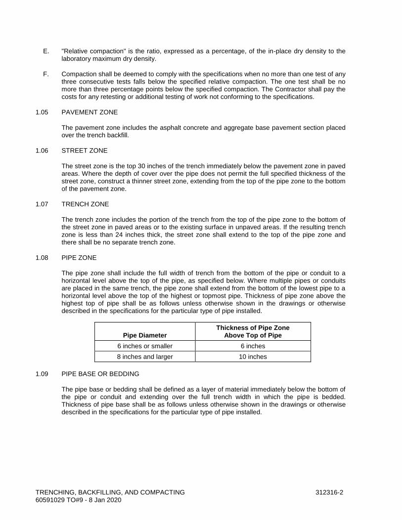
TRENCHING, BACKFILLING, AND COMPACTING 312316-2 60591029 TO#9 - 8 Jan 2020
E. "Relative compaction" is the ratio, expressed as a percentage, of the in-place dry density to the laboratory maximum dry density.
F. Compaction shall be deemed to comply with the specifications when no more than one test of any three consecutive tests falls below the specified relative compaction. The one test shall be no more than three percentage points below the specified compaction. The Contractor shall pay the costs for any retesting or additional testing of work not conforming to the specifications.
1.05 PAVEMENT ZONE
The pavement zone includes the asphalt concrete and aggregate base pavement section placed over the trench backfill.
1.06 STREET ZONE
The street zone is the top 30 inches of the trench immediately below the pavement zone in paved areas. Where the depth of cover over the pipe does not permit the full specified thickness of the street zone, construct a thinner street zone, extending from the top of the pipe zone to the bottom of the pavement zone.
1.07 TRENCH ZONE
The trench zone includes the portion of the trench from the top of the pipe zone to the bottom of the street zone in paved areas or to the existing surface in unpaved areas. If the resulting trench zone is less than 24 inches thick, the street zone shall extend to the top of the pipe zone and there shall be no separate trench zone.
1.08 PIPE ZONE
The pipe zone shall include the full width of trench from the bottom of the pipe or conduit to a horizontal level above the top of the pipe, as specified below. Where multiple pipes or conduits are placed in the same trench, the pipe zone shall extend from the bottom of the lowest pipe to a horizontal level above the top of the highest or topmost pipe. Thickness of pipe zone above the highest top of pipe shall be as follows unless otherwise shown in the drawings or otherwise described in the specifications for the particular type of pipe installed.
Pipe Diameter
Thickness of Pipe Zone Above Top of Pipe
6 inches or smaller 6 inches
8 inches and larger 10 inches
1.09 PIPE BASE OR BEDDING
The pipe base or bedding shall be defined as a layer of material immediately below the bottom of the pipe or conduit and extending over the full trench width in which the pipe is bedded. Thickness of pipe base shall be as follows unless otherwise shown in the drawings or otherwise described in the specifications for the particular type of pipe installed.
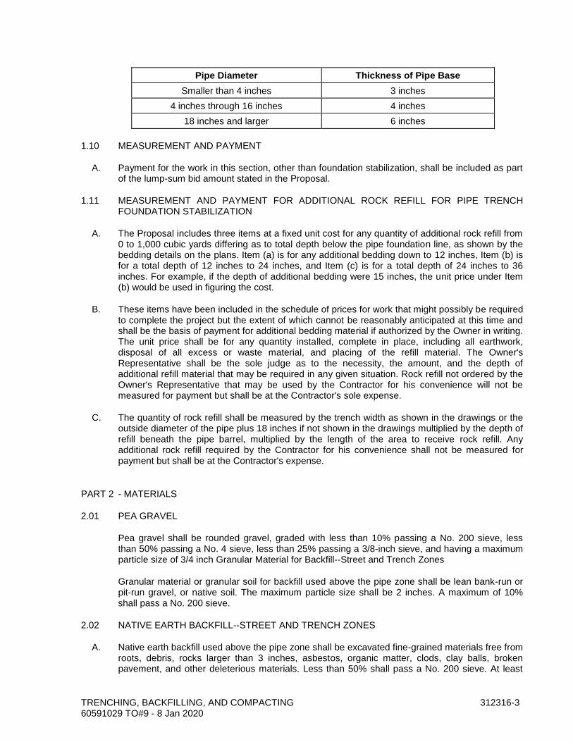
TRENCHING, BACKFILLING, AND COMPACTING 312316-3 60591029 TO#9 - 8 Jan 2020
Pipe Diameter Thickness of Pipe Base
Smaller than 4 inches 3 inches
4 inches through 16 inches 4 inches
18 inches and larger 6 inches
1.10 MEASUREMENT AND PAYMENT
A. Payment for the work in this section, other than foundation stabilization, shall be included as part of the lump-sum bid amount stated in the Proposal.
1.11 MEASUREMENT AND PAYMENT FOR ADDITIONAL ROCK REFILL FOR PIPE TRENCH FOUNDATION STABILIZATION
A. The Proposal includes three items at a fixed unit cost for any quantity of additional rock refill from 0 to 1,000 cubic yards differing as to total depth below the pipe foundation line, as shown by the bedding details on the plans. Item (a) is for any additional bedding down to 12 inches, Item (b) is for a total depth of 12 inches to 24 inches, and Item (c) is for a total depth of 24 inches to 36 inches. For example, if the depth of additional bedding were 15 inches, the unit price under Item (b) would be used in figuring the cost.
B. These items have been included in the schedule of prices for work that might possibly be required to complete the project but the extent of which cannot be reasonably anticipated at this time and shall be the basis of payment for additional bedding material if authorized by the Owner in writing. The unit price shall be for any quantity installed, complete in place, including all earthwork, disposal of all excess or waste material, and placing of the refill material. The Owner's Representative shall be the sole judge as to the necessity, the amount, and the depth of additional refill material that may be required in any given situation. Rock refill not ordered by the Owner's Representative that may be used by the Contractor for his convenience will not be measured for payment but shall be at the Contractor's sole expense.
C. The quantity of rock refill shall be measured by the trench width as shown in the drawings or the outside diameter of the pipe plus 18 inches if not shown in the drawings multiplied by the depth of refill beneath the pipe barrel, multiplied by the length of the area to receive rock refill. Any additional rock refill required by the Contractor for his convenience shall not be measured for payment but shall be at the Contractor's expense.
PART 2 - MATERIALS
2.01 PEA GRAVEL
Pea gravel shall be rounded gravel, graded with less than 10% passing a No. 200 sieve, less than 50% passing a No. 4 sieve, less than 25% passing a 3/8-inch sieve, and having a maximum particle size of 3/4 inch Granular Material for Backfill--Street and Trench Zones
Granular material or granular soil for backfill used above the pipe zone shall be lean bank-run or pit-run gravel, or native soil. The maximum particle size shall be 2 inches. A maximum of 10% shall pass a No. 200 sieve.
2.02 NATIVE EARTH BACKFILL--STREET AND TRENCH ZONES
A. Native earth backfill used above the pipe zone shall be excavated fine-grained materials free from roots, debris, rocks larger than 3 inches, asbestos, organic matter, clods, clay balls, broken pavement, and other deleterious materials. Less than 50% shall pass a No. 200 sieve. At least
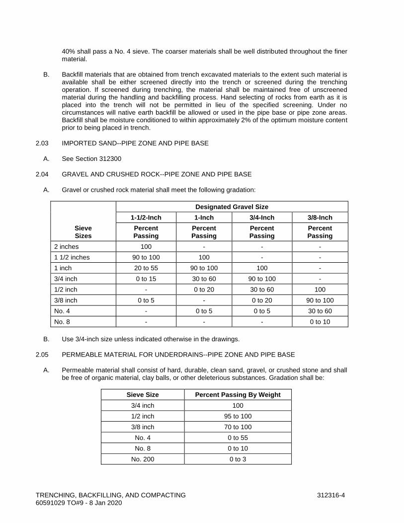
TRENCHING, BACKFILLING, AND COMPACTING 312316-4 60591029 TO#9 - 8 Jan 2020
40% shall pass a No. 4 sieve. The coarser materials shall be well distributed throughout the finer material.
B. Backfill materials that are obtained from trench excavated materials to the extent such material is available shall be either screened directly into the trench or screened during the trenching operation. If screened during trenching, the material shall be maintained free of unscreened material during the handling and backfilling process. Hand selecting of rocks from earth as it is placed into the trench will not be permitted in lieu of the specified screening. Under no circumstances will native earth backfill be allowed or used in the pipe base or pipe zone areas. Backfill shall be moisture conditioned to within approximately 2% of the optimum moisture content prior to being placed in trench.
2.03 IMPORTED SAND--PIPE ZONE AND PIPE BASE
A. See Section 312300
2.04 GRAVEL AND CRUSHED ROCK--PIPE ZONE AND PIPE BASE
A. Gravel or crushed rock material shall meet the following gradation:
Sieve Sizes
Designated Gravel Size
1-1/2-Inch 1-Inch 3/4-Inch 3/8-Inch
Percent Passing
Percent Passing
Percent Passing
Percent Passing
2 inches 100 - - -
1 1/2 inches 90 to 100 100 - -
1 inch 20 to 55 90 to 100 100 -
3/4 inch 0 to 15 30 to 60 90 to 100 -
1/2 inch - 0 to 20 30 to 60 100
3/8 inch 0 to 5 - 0 to 20 90 to 100
No. 4 - 0 to 5 0 to 5 30 to 60
No. 8 - - - 0 to 10
B. Use 3/4-inch size unless indicated otherwise in the drawings.
2.05 PERMEABLE MATERIAL FOR UNDERDRAINS--PIPE ZONE AND PIPE BASE
A. Permeable material shall consist of hard, durable, clean sand, gravel, or crushed stone and shall be free of organic material, clay balls, or other deleterious substances. Gradation shall be:
Sieve Size Percent Passing By Weight
3/4 inch 100
1/2 inch 95 to 100
3/8 inch 70 to 100
No. 4 0 to 55
No. 8 0 to 10
No. 200 0 to 3
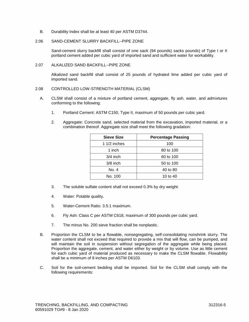
TRENCHING, BACKFILLING, AND COMPACTING 312316-5 60591029 TO#9 - 8 Jan 2020
B. Durability Index shall be at least 40 per ASTM D3744.
2.06 SAND-CEMENT SLURRY BACKFILL--PIPE ZONE
Sand-cement slurry backfill shall consist of one sack (94 pounds) sacks pounds) of Type I or II portland cement added per cubic yard of imported sand and sufficient water for workability.
2.07 ALKALIZED SAND BACKFILL--PIPE ZONE
Alkalized sand backfill shall consist of 25 pounds of hydrated lime added per cubic yard of imported sand.
2.08 CONTROLLED LOW-STRENGTH MATERIAL (CLSM)
A. CLSM shall consist of a mixture of portland cement, aggregate, fly ash, water, and admixtures conforming to the following:
1. Portland Cement: ASTM C150, Type II, maximum of 50 pounds per cubic yard.
2. Aggregate: Concrete sand, selected material from the excavation, imported material, or a combination thereof. Aggregate size shall meet the following gradation:
Sieve Size Percentage Passing
1 1/2 inches 100
1 inch 80 to 100
3/4 inch 60 to 100
3/8 inch 50 to 100
No. 4 40 to 80
No. 100 10 to 40
3. The soluble sulfate content shall not exceed 0.3% by dry weight.
4. Water: Potable quality.
5. Water-Cement Ratio: 3.5:1 maximum.
6. Fly Ash: Class C per ASTM C618, maximum of 300 pounds per cubic yard.
7. The minus No. 200 sieve fraction shall be nonplastic.
B. Proportion the CLSM to be a flowable, nonsegregating, self-consolidating nonshrink slurry. The water content shall not exceed that required to provide a mix that will flow, can be pumped, and will maintain the soil in suspension without segregation of the aggregate while being placed. Proportion the aggregate, cement, and water either by weight or by volume. Use as little cement for each cubic yard of material produced as necessary to make the CLSM flowable. Flowability shall be a minimum of 8 inches per ASTM D6103.
C. Soil for the soil-cement bedding shall be imported. Soil for the CLSM shall comply with the following requirements:
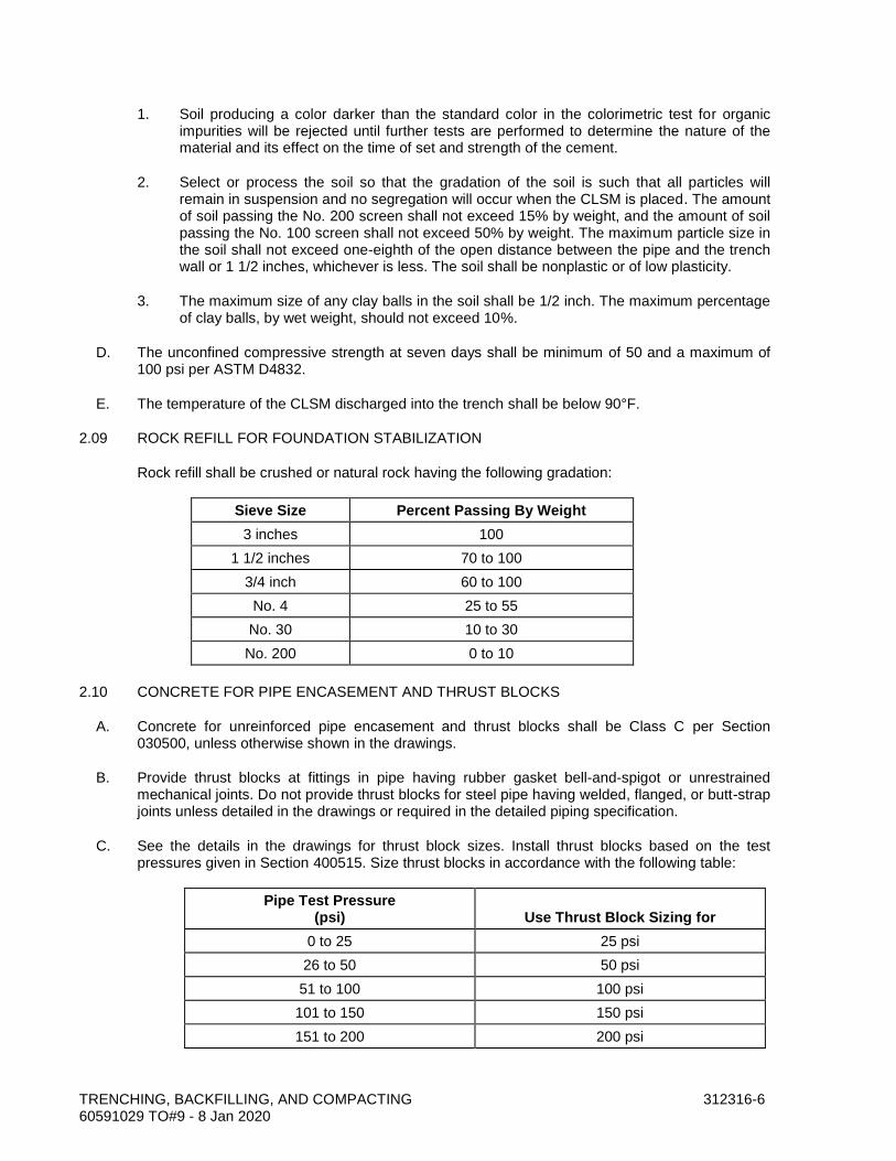
TRENCHING, BACKFILLING, AND COMPACTING 312316-6 60591029 TO#9 - 8 Jan 2020
1. Soil producing a color darker than the standard color in the colorimetric test for organic impurities will be rejected until further tests are performed to determine the nature of the material and its effect on the time of set and strength of the cement.
2. Select or process the soil so that the gradation of the soil is such that all particles will remain in suspension and no segregation will occur when the CLSM is placed. The amount of soil passing the No. 200 screen shall not exceed 15% by weight, and the amount of soil passing the No. 100 screen shall not exceed 50% by weight. The maximum particle size in the soil shall not exceed one-eighth of the open distance between the pipe and the trench wall or 1 1/2 inches, whichever is less. The soil shall be nonplastic or of low plasticity.
3. The maximum size of any clay balls in the soil shall be 1/2 inch. The maximum percentage of clay balls, by wet weight, should not exceed 10%.
D. The unconfined compressive strength at seven days shall be minimum of 50 and a maximum of 100 psi per ASTM D4832.
E. The temperature of the CLSM discharged into the trench shall be below 90°F.
2.09 ROCK REFILL FOR FOUNDATION STABILIZATION
Rock refill shall be crushed or natural rock having the following gradation:
Sieve Size Percent Passing By Weight
3 inches 100
1 1/2 inches 70 to 100
3/4 inch 60 to 100
No. 4 25 to 55
No. 30 10 to 30
No. 200 0 to 10
2.10 CONCRETE FOR PIPE ENCASEMENT AND THRUST BLOCKS
A. Concrete for unreinforced pipe encasement and thrust blocks shall be Class C per Section 030500, unless otherwise shown in the drawings.
B. Provide thrust blocks at fittings in pipe having rubber gasket bell-and-spigot or unrestrained mechanical joints. Do not provide thrust blocks for steel pipe having welded, flanged, or butt-strap joints unless detailed in the drawings or required in the detailed piping specification.
C. See the details in the drawings for thrust block sizes. Install thrust blocks based on the test pressures given in Section 400515. Size thrust blocks in accordance with the following table:
Pipe Test Pressure (psi)
Use Thrust Block Sizing for
0 to 25 25 psi
26 to 50 50 psi
51 to 100 100 psi
101 to 150 150 psi
151 to 200 200 psi

TRENCHING, BACKFILLING, AND COMPACTING 312316-7 60591029 TO#9 - 8 Jan 2020
D. Dimensions of thrust blocks for pipes smaller than 6 inches shall be the same as the dimensions shown for 6-inch pipe, unless specific dimensions are shown in the drawings.
2.11 WATER FOR COMPACTION
See Section 312300. Water shall be free of organic materials injurious to the pipe coatings.
2.12 UNDERGROUND PLASTIC WARNING TAPE FOR METAL PIPE
See Section 400775.
2.13 UNDERGROUND DETECTABLE METALLIC PIPE WARNING TAPE
See Section 400775.
PART 3 - EXECUTION
3.01 SLOPING, SHEETING, SHORING, AND BRACING OF TRENCHES
Trenches shall have sloping, sheeting, shoring, and bracing conforming with 29CFR1926, Subpart P--Excavations, CAL/OSHA requirements, and the Special Provisions.
3.02 SIDEWALK, PAVEMENT, AND CURB REMOVAL
Cut bituminous and concrete pavements regardless of the thickness and curbs and sidewalks prior to excavation of the trenches with a pavement saw or pavement cutter. Width of the pavement cut shall be at least equal to the required width of the trench at ground surface. Haul pavement and concrete materials from the site. Do not use for trench backfill.
3.03 TRENCH EXCAVATION
A. Excavate the trench to the lines and grades shown in the drawings with allowance for pipe thickness, sheeting and shoring if used, and for pipe base or special bedding. If the trench is excavated below the required grade, refill any part of the trench excavated below the grade at no additional cost to the Owner with pea gravel of the type specified for the type of pipe granular material foundation stabilization material. Place the refilling material over the full width of trench in compacted layers not exceeding 6 inches deep to the established grade with allowance for the pipe base or special bedding.
B. Trench widths in the pipe zone shall be as shown in the drawings. If no details are shown, maximum width shall be 18 inches greater than the pipe outside diameter. Comply with 29CFR Part 1926 Subpart P--Excavations. Trench width at the top of the trench will not be limited except where width of excavation would undercut adjacent structures and footings. In such case, width of trench shall be such that there is at least 2 feet between the top edge of the trench and the structure or footing.
3.04 TRENCH EXCAVATION IN BACKFILL AND EMBANKMENT AREAS
A. Construct and compact the embankment to an elevation of 1-foot minimum over the top of the largest pipe or conduit to be installed.
B. Excavate trench in the compacted backfill or embankment.
TRENCHING, BACKFILLING, AND COMPACTING 312316-8 60591029 TO#9 - 8 Jan 2020
3.05 LOCATION OF EXCAVATED MATERIAL
A. During trench excavation, place the excavated material only within the working area. Do not obstruct any roadways or streets. Do not place trench spoil over pipe, buried utilities, manholes, or vaults. Conform to federal, state, and local codes governing the safe loading of trenches with excavated material.
3.06 DEWATERING
Provide and maintain means and devices to remove and dispose of water entering the trench excavation during the time the trench is being prepared for the pipe laying, during the laying of the pipe, and until the backfill at the pipe zone has been completed. These provisions shall apply during both working and nonworking hours, including lunchtime, evenings, weekends, and holidays. Dispose of the water in a manner to prevent damage to adjacent property and in accordance with regulatory agency requirements. Do not drain trench water through the pipeline under construction. Do not allow groundwater to rise around the pipe until jointing compound has set hard.
3.07 FOUNDATION STABILIZATION
A. After the required excavation has been completed, the Owner will inspect the exposed subgrade to determine the need for any additional excavation. It is the intent that additional excavation be conducted in all areas within the influence of the pipeline where unacceptable materials exist at the exposed subgrade. Overexcavation shall include the removal of all such unacceptable material that exist directly beneath the pipeline to a width 24 inches greater than the pipe outside diameter and to the depth required.
B. Place filter fabric on the bottom of the trench and up the sides a sufficient height to retain rock refill material. Backfill the trench to subgrade of pipe base with rock refill material for foundation stabilization. Place the foundation stabilization material over the full width of the trench and compact in layers not exceeding 8inches deep to the required grade. Foundation stabilization work shall be executed in accordance with a change order.
C. Rock refill used by the Contractor for his convenience will not be cause for any additional payment.
3.08 INSTALLING BURIED PIPING
A. Grade the bottom of the trench to the line and grade to which the pipe is to be laid, with allowance for pipe thickness. Remove hard spots that would prevent a uniform thickness of bedding. Place the specified thickness of pipe base material over the full width of trench. Grade the top of the pipe base ahead of the pipe laying to provide firm, continuous, uniform support along the full length of pipe, and compact to the relative compaction specified herein. Before laying each section of the pipe, check the grade and correct any irregularities.
B. Excavate bell holes at each joint to permit proper assembly and inspection of the entire joint. Fill the area excavated for the joints with the bedding material specified or indicated in the drawings for use in the pipe zone. If no bedding material is specified or indicated, use imported sand.
C. Inspect each pipe and fitting before lowering the buried pipe or fitting into the trench. Inspect the interior and exterior protective coatings. Patch damaged areas in the field with material recommended by the protective coating manufacturer. Clean ends of pipe thoroughly. Remove foreign matter and dirt from inside of pipe and keep clean during and after installation.

TRENCHING, BACKFILLING, AND COMPACTING 312316-9 60591029 TO#9 - 8 Jan 2020
D. Handle pipe in such a manner as to avoid damage to the pipe. Do not drop or dump pipe into trenches under any circumstances.
E. When installing pipe, do not deviate more than 1 inch from line ¼ inch from grade. Measure elevation at the pipe invert.
F. After pipe has been bedded, place pipe zone material simultaneously on both sides of the pipe, in maximum 6-inch lifts, keeping the level of backfill the same on each side. If no pipe zone material is specified or indicated, use imported sand. Carefully place the material around the pipe so that the pipe barrel is completely supported and no voids or uncompacted areas are left beneath the pipe. Use particular care in placing material on the underside of the pipe to prevent lateral movement during subsequent backfilling.
G. Compact each lift to the relative compaction specified herein.
H. Push the backfill material carefully onto the backfill previously placed in the pipe zone. If no backfill material is otherwise specified or indicated, use granular material for backfill. Do not permit free-fall of the material until at least 2 feet of cover is provided over the top of the pipe. Do not drop sharp, heavy pieces of material directly onto the pipe or the tamped material around the pipe. Do not operate heavy equipment or a sheepsfoot wheel mounted on a backhoe over the pipe until at least 3 feet or one-half of the internal diameter, whichever is greater, of backfill has been placed and compacted over the pipe.
I. When the pipe laying is not in progress, including the noon hours, close the open ends of pipe. Do not allow trench water, animals, or foreign material to enter the pipe.
J. Keep the trench dry until the pipe laying and jointing are completed.
3.09 BACKFILL COMPACTION
A. Unless otherwise shown in the drawings or otherwise described in the specifications for the particular type of pipe installed, relative compaction in pipe trenches shall be as follows:
1. Pipe Zone: 90% relative compaction.
2. Backfill in Trench Zone Not Beneath Paving: 90%relative compact ion. Compact backfill within embankment above the pipe zone to the same relative compaction as the adjacent embankment as specified in Section 312300.
3. Backfill in Trench Zone to Street Zone in Paved Areas: 90% relative compaction.
4. Backfill in Street Zone in Paved Areas: 95% relative compaction.
5. Rock Refill for Foundation Stabilization: 80% relative density.
6. Refill for Overexcavation: 80% relative density.
B. Compact trench backfill to the specified relative compaction. Compact by using mechanical compaction or hand tamping. Do not use high-impact hammer-type equipment except where the pipe manufacturer warrants in writing that such use will not damage the pipe.
C. Compact material placed within 12 inches of the outer surface of the pipe by hand tamping only.
D. Do not use any axle-driven or tractor-drawn compaction equipment within 5 feet of building walls, foundations, and other structures.
TRENCHING, BACKFILLING, AND COMPACTING 312316-10 60591029 TO#9 - 8 Jan 2020
3.10 MATERIAL REPLACEMENT
Remove and replace any trenching and backfilling material that does not meet the specifications, at the Contractor's expense.
3.11 PLACING SAND-CEMENT SLURRY BACKFILL
Place sand-cement slurry backfill in a uniform manner that will prevent voids in or segregation of the material. Remove foreign material that falls into the excavation or trench. Do not commence backfilling over or place any material over the slurry cement backfill until at least four hours after placing the sand-cement slurry.
3.12 PLACEMENT OF CLSM
A. Provide batching equipment to obtain the proper weights of soil, cement, water, and admixtures. Measuring devices shall be sensitive to a 2% variation above or below the actual weights required. Volumetric batching may be used, provided the same accuracy required for weight batching is maintained.
B. Design and operate the mixers used for mixing the CLSM so that the CLSM as discharged from the mixer is uniform in composition and consistency throughout each batch.
C. Place the CLSM such that it flows easily into all openings between the pipe and the excavated trench. In some cases, such as trenches on a slope, a stiffer mix may be required to prevent it from flowing down the trench. In this case, use vibration to ensure that the CLSM completely fills all spaces.
D. Lay the pipe on the soil pads and place the CLSM bedding as shown in the drawings. Place bedding under pipe from one side and vibrate so that it flows under the pipe until it appears on the other side. Then add CLSM to both sides of the pipe and vibrate until it completely fills the space between the pipe and the excavated trench bottom. This operation shall follow as closely behind pipe laying operations as possible. Place CLSM in such a way as to prevent uplift or buckling of the pipe. Deposit CLSM as nearly as practicable in its final position. Do not disturb the pipe trench or cause foreign material to become mixed with the cement slurry.
E. Do not place backfill above the pipe until the CLSM has reached the initial set. Place and maintain a 6-inch cover of moist backfill cover until additional backfill is placed. If the ambient temperature is 50°F or less, place an additional 6-inch cover of backfill over the 6-inch moist backfill cover prior to the end of the working day.
F. Whenever freezing temperatures are imminent, maintain the CLSM at a temperature of not less than 50°F for 24 hours after placement. The temperature of the mix shall be 50°F or greater at the time of placement. Monitor the temperature by placing a thermometer in the CLSM immediately after sampling at the placement site. When freezing weather appears imminent, make ready at the placement site materials that may be required for protection of the CLSM. Delay placement of CLSM until adequate provisions for protection against weather are made. Do not place CLSM bedding in pipe trenches when the trench bottom or walls are frozen or contain frozen material. Backfill placed as cover over the CLSM is prohibited from containing any frozen material.
END OF SECTION

FLOWABLE FILL 312323-1 60591029 TO#9 - 8 Jan 2020
SECTION 312323 FLOWABLE FILL
PART 1 GENERAL
1.01 SECTION INCLUDES
A. CONTRACTOR shall furnish and place controlled low strength material (CLSM) backfill bedding where shown in the DRAWINGS.
1.02 RELATED SECTIONS
A. The following is a list of specifications which may be related to this section:
1. Section 024100 Equipment, Piping, and Material Demolition
1.03 REFERENCES
A. Submit reports and shop drawings in accordance with the Special Provisions.
B. The following is a list of standards which may be referenced in this section:
1. ASTM International (ASTM):
a. C33, Standard Specification for Concrete Aggregates.
b. C94, Standard Specification for Ready-Mixed Concrete.
c. C143/C143M, Standard Test Method for Slump of Hydraulic-Cement Concrete.
d. C150, Standard Specification for Portland Cement.
e. C494/C494M Rev A, Standard Specification for Chemical Admixtures for Concrete.
f. C618, Standard Specification for Coal Fly Ash and Raw or Calcined Natural Pozzolan for Use in Concrete.
g. D4832, Standard Test Method for Preparation and Testing of Controlled Low Strength (CLSM) Test Cylinders.
h. D5971, Standard Practice for Sampling Freshly Mixed Controlled Low-Strength Material.
i. D6023, Standard Test Method for Density (Unit Weight), Yield, Cement Content, and Air Content (Gravimetric) of Controlled Low-Strength Material (CLSM).
j. D6024, Standard Test Method for Ball Drop on Controlled Low-Strength Material (CLSM) to Determine Suitability for Load Application.
k. D6103, Standard Test Method for Flow Consistency of Controlled Low-Strength Material (CLSM).

FLOWABLE FILL 312323-2 60591029 TO#9 - 8 Jan 2020
1.04 SUBMITTALS
A. A minimum of five (5) days prior to starting CLSM WORK. Provide product data on the following:
1. CLSM mix design
2. Fly Ash
3. Admixtures
PART 2 PRODUCTS
2.01 MATERIALS
A. General:
1. The CLSM shall consist of a mixture of sand, coarse aggregate, cement and water.
2. Fly ash and approved admixtures may be used to obtain the required properties of the mix.
3. The mix shall have good workability and flowability with self-compacting and self-leveling characteristics.
4. No changes shall be made in the amounts or sources of the approved mix ingredients without the approval of ENGINEER.
5. Product inspection and field-testing of the approved mix may be made by, or on behalf of, OWNER.
B. Cement: All cement used shall be Type II Portland cement which shall conform to the requirements of ASTM C150.
C. Fly Ash: Fly ash may be either Class C or Class F. The fly ash shall conform to ASTM C618.
D. Aggregates:
1. Fine Aggregate: All fine aggregate shall conform to the grading and quality requirements of ASTM C33.
2. Coarse Aggregate: Coarse aggregate shall conform to the grading and quality requirements of ASTM C33 for size No. 476, No. 57, or No. 67.
E. Water: The batch mixing water and mixer washout water shall conform to the requirements of ASTM C94.
F. Admixtures:
1. Chemical admixtures that do not contain calcium chloride and conform to ASTM C494/C494M for concrete may be used in the CLSM mix.
2. All chemical admixtures shall be compatible with the cement and all other admixtures in the batch.

FLOWABLE FILL 312323-3 60591029 TO#9 - 8 Jan 2020
G. CLSM Proportions:
1. Strength: CLSM shall have a minimum twenty-eight (28) day compressive strength of one hundred (100) psi when molded and cured as in conformance with ASTM D4832.
2. The CLSM shall have a minimum cement content of fifty (50) pounds per cubic yard. The water-cementitious materials ratio of the mix shall not exceed three and one-half to one (3.5:1).
3. Air-Entrainment: All CLSM shall be air entrained to a total air content of approximately five percent (5%).
4. Slump: The minimum slump shall be six (6) inches and the maximum slump shall be eight (8) inches when tested in accordance with ASTM D6103.
5. Aggregate: Fine aggregate shall be between fifty percent (50%) and sixty percent (60%) by volume of the total aggregates in the CLSM mix.
6. Consistency:
a. The consistency of the CLSM slurry shall be such that the material flows easily into all openings between the pipe and the lower portion of the trench.
b. When trenches are on a steep slope, a stiffer mix of slurry may be required to prevent CLSM from flowing down the trench.
c. When a stiffer mix is used, vibration shall be performed to ensure that the CLSM slurry completely fills all spaces between the pipe and the lower portion of the trench.
PART 3 EXECUTION
3.01 GENERAL
A. CLSM shall not be placed when the air temperature is below forty degrees Fahrenheit (40°F) unless the air temperature is thirty five degrees Fahrenheit (35°F) or more and the temperature is rising.
3.02 PLACEMENT
A. Pipe shall be placed in a minimum of 4 lifts.
B. Contractor shall assure the Lift Station 9 dry well dome is completely filled by venting the top as necessary. Observation pipe shall be installed in the peak of the dome to confirm the dry is completely filled.
END OF SECTION

FLOWABLE FILL 312323-4 60591029 TO#9 - 8 Jan 2020
THIS PAGE INTENTIONALLY LEFT BLANK
ASPHALT CONCRETE PAVING 321216-1 60591029 TO#9 - 8 Jan 2020
SECTION 321216 ASPHALT CONCRETE PAVING
PART 1 - GENERAL
1.01 DESCRIPTION
This section includes materials, testing, and installation of asphalt concrete pavement, aggregate base course, herbicide, prime coat, tack coat, seal coat, striping paint, and pavement markers.
1.02 RELATED WORK SPECIFIED ELSEWHERE
A. Earthwork: 312300.
B. Concrete Curbs, Gutters, and Sidewalks: 321613.
1.03 SUBMITTALS
A. Submit reports and shop drawings in accordance with the Special Provisions.
B. Submit a report from a testing laboratory verifying that aggregate material conforms to the specified gradations or characteristics.
C. Submit manufacturer's certificate of compliance or product literature for the following materials:
1. Aggregate: Gradation.
2. Asphalt for Binder: Type and grade.
3. Prime Coat: Type and grade of asphalt.
4. Tack Coat: Type and grade of asphalt.
5. Seal Coat: Type and grade of asphalt.
6. Mixes: Conforms to job-mix formula.
7. Herbicide.
8. Paint for traffic and parking lot striping.
9. Pavement markers.
1.04 TESTING FOR COMPACTION
A. The Owner will test for compaction as described in Section 312300.
B. Determine the density of soil in place by the sand cone method, ASTM D1556 Compaction tests will be performed for each lift or layer.
C. Determine laboratory moisture-density relations of soils by ASTM D1557. If nuclear methods are used for in-place density determination, adjust the compaction test results for maximum dry density and optimum water content in accordance with ASTM D4718. This will be required for determination of percent relative compaction and moisture variation from optimum.

ASPHALT CONCRETE PAVING 321216-2 60591029 TO#9 - 8 Jan 2020
D. Determine the relative density of cohesionless soils by ASTM D4253 and D4254.
E. Sample backfill materials by ASTM D75.
F. "Relative compaction" is the ratio, expressed as a percentage, of the inplace dry density to the laboratory maximum dry density.
G. Compaction shall be deemed to comply with the specifications when no more than one test of any three consecutive tests falls below the specified relative compaction. The one test shall be no more than three percentage points below the specified compaction. The Contractor shall pay the costs of any retesting of work not conforming to the specifications.
1.05 STANDARD SPECIFICATIONS
Wherever reference is made to the Caltrans Standard Specifications such reference shall mean the State of California, Business, Transportation, and Housing Agency, Department of Transportation Standard Specifications, latest edition.
1.06 MEASUREMENT AND PAYMENT
A. Include allowances for pavement removal in the lump sum or unit prices bid for the work. No extra compensation will be made should the existing pavement sections vary from the conditions as listed or described.
PART 2 - MATERIALS
2.01 ASPHALT CONCRETE PAVING
Asphalt concrete paving shall conform to Type A or B in Section 39 of the Caltrans Standard Specifications, having 1/2-inch-maximum medium grading PG 64-10 asphalt per Section 92 in the Caltrans Standard Specifications.
2.02 AGGREGATE BASE COURSE
Aggregate base shall be Class 2 aggregate base, 3/4-inch-maximum size per Section 26 of the Caltrans Standard Specifications.
2.03 PRIME COAT
All areas to be paved shall receive prime coat. Prime coat shall be per Section 39-4.02 in the Caltrans Standard Specifications.
2.04 TACK COAT
Tack coat shall conform with Section 94, Grade SS1hin the Caltrans Standard Specifications.
2.05 ASPHALT
Asphalt shall be Performance Grade PG 64-10 per Section 92 in the Caltrans Standard Specifications. Asphalt content in the pavement shall be 5.5% to 6.0%.
2.06 AGGREGATE FOR ASPHALT CONCRETE
Aggregate shall be Type A or B per Section 39-2.02 in the Caltrans Standard Specifications
ASPHALT CONCRETE PAVING 321216-3 60591029 TO#9 - 8 Jan 2020
2.07 SEAL COAT
Seal coat shall be Type II slurry seal per Section 37 of the Caltrans Standard Specifications fog type per Section 37 of the Caltrans Standard Specifications SS1 asphaltic emulsion per Section 94 of the Caltrans Standard Specifications.
2.08 WOOD HEADERS
Size of wood headers shall be 2 inches by the depth of the asphalt concrete paving; minimum size shall be 2 inches by 4 inches. Wood shall be Douglas fir No. 1. Wood shall comply with Section 57 of the Caltrans Standard Specifications.
2.09 HERBICIDE OR WEED KILLER
Use Gallery (Isoxaben) or Surflan (Oryzalin) by Dow AgroSciences, Pre-M (Pendimethalin) by American Cyanamid Co., or equal.
2.10 PAINT FOR TRAFFIC AND PARKING LOT STRIPING AND MARKING
Provide rapid-dry or fast-dry paint per Section 84 of the Caltrans Standard Specifications.
PART 3 - EXECUTION
3.01 PAVEMENT REMOVAL
A. Initially cut asphalt concrete pavement with pneumatic pavement cutter or other equipment at the limits of the excavation and remove the pavement. After backfilling the excavation, saw cut asphalt concrete pavement to a minimum depth of 2 inches at a point not less than 9 inches outside the limits of the excavation or the previous pavement cut, whichever is greater, and remove the additional pavement.
B. Saw cut concrete pavement, including cross gutters, curbs and gutters, sidewalks, and driveways, to a minimum depth of 1 1/2 inches at a point 1 foot beyond the edge of the excavation and remove the pavement. The concrete pavement may initially be cut at the limits of the excavation by other methods prior to removal and the saw cut made after backfilling the excavation. If the saw cut falls within 3 feet of a concrete joint or pavement edge, remove the concrete to the joint or edge.
C. Make arrangements for and dispose of the removed pavement.
D. Final pavement saw cuts shall be straight along both sides of trenches, parallel to the pipeline alignment, and provide clean, solid, vertical faces free from loose material. Saw cut and remove damaged or disturbed adjoining pavement. Saw cuts shall be parallel to the pipeline alignment or the roadway centerline or perpendicular to same.
E. The Owner's Representative has reviewed existing street improvement data along the route of the project to try to determine the type and depth of the existing pavement sections within the trench prism. The Owner does not guarantee the accuracy of this determination of the pavement sections.

ASPHALT CONCRETE PAVING 321216-4 60591029 TO#9 - 8 Jan 2020
3.02 NSTALLATION
Producing, hauling, placing, compacting, and finishing of asphalt concrete shall conform to Section 39 of the Caltrans Standard Specifications. Apply seal coat to all paving except open asphalt concrete.
3.03 CONNECTIONS WITH EXISTING PAVEMENT
Where new paving joins existing paving, chip the existing surfaces 12 inches back from the joint line so that there will be sufficient depth to provide a minimum of 1 inch of asphalt concrete. Dispose of waste material offsite. Tack chipped areas prior to placing the asphalt concrete. Meet lines shall be straight and the edges vertical. Paint the edges of meet line cuts with liquid asphalt or emulsified asphalt prior to placing asphalt concrete. After placing the asphalt concrete, seal the meet line by painting with a liquid asphalt or emulsified asphalt and then immediately cover with clean, dry sand.
3.04 PREPARATION OF SUBGRADE
A. Excavate and shape subgrade to line, grade, and cross section shown in the drawings. The subgrade shall be considered to extend over the full width of the base course.
B. Scarify and cultivate the top 6 inches of subgrade when the subgrade consists of dry soils which are impervious to the penetration of water, soils which contain excessive amounts of moisture which may result in unstable foundations, soils which are nonuniform in character which may result in nonuniform relative compactions and subsequent differential settlements of finished surfaces, or when pavement is to be placed directly on the roadbed material.
C. After rough grading has been completed, when scarifying and cultivating are required, loosen the roadbed to a depth of at least 6 inches. Work the loosened material to a finely divided condition and remove rocks larger than 2nches in diameter. Bring the moisture content to optimum by the addition of water, by the addition and blending of dry material, or by the drying of existing material. Compact the material to the specified relative compaction.
D. Uniform pervious soils that allow the immediate penetration of water or uniform impervious soils which will allow the penetration of water to a depth of at least 6 inches after the addition of a suitable wetting agent will not require scarifying and cultivating. When scarifying and cultivating are not required, bring the moisture content of the top 6 inches of the subgrade material to optimum by the addition of water at the surface, and compact the material to the specified relative compaction.
E. Remove soft material disclosed by the subgrade preparation, replace with structural backfill material per Section 312300 or aggregate base course material, and recompact.
F. Compact the top 6 inches of subgrade to 90% relative compaction.
G. The finished subgrade shall be within a tolerance of ±0.08 of a foot of the grade and cross-section shown and shall be smooth and free from irregularities and at the specified relative compaction.
3.05 INSTALLING WOOD HEADERS
Provide wood header at edges of paving except where paving is adjacent to concrete slabs, gutters, walks, existing paving, or structures.

ASPHALT CONCRETE PAVING 321216-5 60591029 TO#9 - 8 Jan 2020
3.06 PLACING AGGREGATE BASE COURSE
Place aggregate base course to a minimum thickness of 6 inches, unless shown otherwise in the drawings. Compact to 95% relative compaction. Install in accordance with Section 26 of the Caltrans Standard Specifications.
3.07 COMPACTION OF AGGREGATE BASE AND LEVELING COURSES
Compaction and rolling shall begin at the outer edges of the surfacing and continue toward the center. Apply water uniformly throughout the material to provide moisture for obtaining the specified compaction. Compact each layer to the specified relative compaction before placing the next layer.
3.08 APPLYING HERBICIDE OR WEED KILLER
Apply weed killer or herbicide on base prior to placing pavement. Apply herbicide along with water at the rate recommended by the manufacturer to control dawny brome grass, puncture vine, and plaintain. Apply from outside of curb to opposite outside of curb and for the full width of roadways and parking areas.
3.09 PLACING PRIME COAT
Apply prime coat to the surface of the leveling course of aggregate base at the rate of 0.25 gallon per square yard per Section 39-4.02 in the Caltrans Standard Specifications.
3.10 PLACING TACK COAT
Apply tack coat on surfaces to receive finish pavement per Section 39-4.02 in the Caltrans Standard Specifications. Apply tack coat to metal or concrete surfaces that will be in contact with the asphalt concrete paving.
3.11 PLACING ASPHALT PAVING
Place asphalt paving to a minimum thickness of 3 inches unless otherwise shown in the drawings. Install in accordance with Section 39-6 in the Caltrans Standard Specifications.
3.12 COMPACTION OF ASPHALT CONCRETE PAVING
Compact until roller marks are eliminated and a density of 92% minimum to 98% maximum has been attained per ASTM D2041.
3.13 APPLYING SEAL COAT
Apply fog-type seal coat at the rate of 0.05 to 0.10 gallon per square yard SS1 asphaltic emulsion per Section 94 of the Caltrans Standard Specifications.
3.14 SURFACE TOLERANCE
A. Finished grade shall not deviate more than 0.02 foot in elevation from the grade indicated in the drawings. Slopes shall not vary more than 1/4 inch in 10 feet from the slopes shown in the drawings.
B. After paving has been installed and compacted, spray water over the entire paved area. Correct any areas where water collects and does not drain away.

ASPHALT CONCRETE PAVING 321216-6 60591029 TO#9 - 8 Jan 2020
C. Apply in accordance with Section 84 of the Caltrans Standard Specifications.
END OF SECTION
CONCRETE CURBS, GUTTERS, AND SIDEWALKS 321613-1 60591029 TO#9 - 8 Jan 2020
SECTION 321613 CONCRETE CURBS, GUTTERS, AND SIDEWALKS
PART 1 - GENERAL
1.01 DESCRIPTION
This section includes materials and installation of concrete curbs, gutters, and sidewalks.
1.02 RELATED WORK SPECIFIED ELSEWHERE
A. General Concrete Construction: 030500.
B. Earthwork: 312300.
1.03 SUBMITTALS
Submit a report from a testing laboratory verifying that crushed rock and aggregate material conforms to the specified gradations or characteristics.
1.04 TESTING FOR COMPACTION
A. The Owner will test for compaction as described in Section 312300.
B. Determine the relative density of cohesionless soils by ASTM D4253 and D4254.
C. Sample backfill materials by ASTM D75.
D. "Relative compaction" is the ratio, expressed as a percentage, of the inplace dry density to the laboratory maximum dry density.
E. Compaction shall be deemed to comply with the specifications when no more than one test of any three consecutive tests falls below the specified relative compaction. The one test shall be no more than three percentage points below the specified compaction. The Contractor shall pay the costs of any retesting of work not conforming to the specifications.
1.05 STANDARD SPECIFICATIONS
Wherever reference is made in this section to the State Specifications, such reference shall be understood to mean the State of California, Business, Transportation, and Housing Agency, Department of Transportation Standard Specifications, latest edition
1.06 MEASUREMENT AND PAYMENT
Measurement and payment provisions and sharing of costs provisions described in the state of California ("Caltrans") specifications are not applicable to this project. Payment for all work described herein and for all work included by reference to the specifications shall be considered as being included in the lump-sum bid amount stated in the project Bid Proposal and no additional payment will be made therefor.

CONCRETE CURBS, GUTTERS, AND SIDEWALKS 321613-2 60591029 TO#9 - 8 Jan 2020
PART 2 - MATERIALS
2.01 FORMS
A. Forms shall conform to the requirements of Section 030500. Provide stakes and bracing materials to hold forms securely in place.
B. Materials for sidewalk forms shall be 2-inch dressed lumber straight and free from defects, or standard metal forms. Where short-radius forms are required, 1-inch dressed lumber or plywood may be used. Provide stakes and bracing materials to hold forms securely in place.
2.02 CRUSHED ROCK BASE
Clean 3/4-inch and smaller crushed rock or crushed gravel, free from foreign material, and conforming to Class 2 aggregate base per Section 26, State of California Standard Specifications.
2.03 EXPANSION JOINT FILLER
Expansion joint filler shall be 1/2 inch thick for curbs and 1/4 inch thick for sidewalks and shall conform to premolded joint filler in Section 030500.
2.04 CONCRETE
Concrete shall be Class A per Section 030500, except that the maximum water-cement ratio for concrete in curbs and gutters shall be 0.55.
2.05 REINFORCING STEEL
Conform to Section 030500.
2.06 CURING COMPOUND
Curing compound shall be as specified in Section 030500.
2.07 EXCAVATION AND BACKFILL
Conform to Section 312300.
PART 3 - EXECUTION
3.01 PREPARATION OF SUBGRADE
Excavate and shape subgrade to line, grade, and cross-section. Compact subgrade until the top 12 inches are compacted to 90% relative compaction. Remove all soft material disclosed by compacting and replace with crushed rock base. The finished subgrade shall be within a tolerance of ±0.08 feet of the grade and cross-section shown and shall be smooth and free from irregularities at the specified relative compaction. The subgrade shall be considered to extend over the full width of the base course.
3.02 PLACING CRUSHED ROCK BASE
After the subgrade for curbs, sidewalks, and roadway slabs is compacted and at the proper grade, spread crushed rock base material. Sprinkle with water and compact. Top of the compacted gravel shall be at the proper level to receive the concrete. Compact crushed rock

CONCRETE CURBS, GUTTERS, AND SIDEWALKS 321613-3 60591029 TO#9 - 8 Jan 2020
base to 90% relative density. Curbs and sidewalks shall receive 4 inches or more of compacted crushed rock base material.
3.03 SETTING FORMS
A. Conform to Section 030500.
B. Forms on the face of the curb shall not have any horizontal joints within 7 inches of the top of the curb. Brace forms to prevent change of shape of movement in any direction resulting from the weight of the concrete during placement. Construct short-radius curved forms to exact radius. Tops of forms shall not depart from gradeline more than 1/8 inch when checked with a 10-foot straightedge. Alignment of straight sections shall not vary more than 1/8 inch in 10 feet.
3.04 CURB CONSTRUCTION
A. Construct curbs to line and grade shown. Curbs shall conform to the details shown.
B. Construct ramps in accordance with the details and locations as shown in the drawings.
C. Place preformed asphalt-impregnated expansion joints at intervals not exceeding 45 feet or less than 15 feet, at the beginning and end of curved portions of the curb, at each change in thickness in section, at the end of curbs at buildings and other structures, and at connections to existing curbs.
D. Place contraction joints in the curb at uniform intervals not exceeding 15 feet.
E. As soon as the concrete has set sufficiently to support its own weight, remove the front form and finish exposed surfaces. Finish formed face by rubbing with a burlap sack or similar device that will produce a uniformly textured surface, free of form marks, honeycomb, and other defects. Remove and replace defective concrete at the Contractor’s expense. Upon completion of the finishing, apply curing compound to exposed surfaces of the curb. Curing shall continue for a minimum of five days.
F. Upon completion of the curing period, but not before seven days have elapsed since pouring the concrete, backfill the curb with earth free from rocks 2 inches and larger and other foreign material. Tamp backfill firmly in place.
G. Finished curb shall present a uniform appearance for both grade and alignment. Remove any section of curb showing abrupt changes in alignment or grade or that is more than 1/4 inch away from its location as staked and construct new curb in its place at no additional cost to the Owner.
3.05 SIDEWALK CONSTRUCTION
A. Sidewalks shall be 4 inches thick in walk areas and 6-inches thick in driveway areas, unless otherwise shown in the drawings. Walks shall slope 1/4 inch per foot away from structures, unless otherwise shown in the drawings.
B. At locations where the new sidewalk is to abut existing concrete, saw concrete for a depth of 2 inches, chip the old concrete down to sound material and a plane surface, clean the surface, and apply a neat cement paste just prior to pouring the new sidewalk.
C. Place preformed asphalt expansion joints at intervals not exceeding 45 feet or less than 15 feet, where the sidewalk ends at a curb, and around posts, poles, or other objects protruding through the sidewalk. Place expansion joints between sidewalks and buildings or other structures.

CONCRETE CURBS, GUTTERS, AND SIDEWALKS 321613-4 60591029 TO#9 - 8 Jan 2020
D. Place preformed asphalt expansion joint material between back of curbs and sidewalks.
E. Provide contraction joints transversely to the walks at locations opposite the contraction joints in the curb and at intervals along the sidewalk such that the distance between contraction joints does not exceed 1.5 times the sidewalk width. These joints shall be 3/16 inch by one-fourth of the slab thickness weakened plane joints. They shall be straight and at right angles to the surface of the walk.
F. Place, process, finish, and cure concrete in conformance with Section 030500.
G. Broom the surface with a fine-hair broom at right angles to the length of the walk and tool at all edges, joints, and markings. Mark the walks transversely at 5-foot intervals with a jointing tool. Upon completion of the finishing, apply a curing compound to exposed surfaces. Protect the sidewalk from damage.
H. Finished sidewalk shall present a uniform appearance for both grade and alignment. Remove any section of sidewalk showing abrupt changes in alignment or grade or that is more than 2 inches away from its location as shown in the drawings and construct new sidewalk in its place at no additional cost to the Owner.
END OF SECTION

LEAKAGE AND INFILTRATION TESTING 330130-1 60591029 TO#9 - 8 Jan 2020
SECTION 330130 LEAKAGE AND INFILTRATION TESTING
PART 1 - GENERAL
1.01 DESCRIPTION
This section includes testing of gravity pipelines, sewers, culverts, drains, and manholes not intended to be pressurized in excess of 5 psi or 12 feet head of water. Leakage test is by internal air pressure or water. Infiltration test is by measurement of rate of flow of water.
PART 2 - MATERIALS
2.01 TEST PLUGS
Inflatable and expandable type, braced to contain 5 psi over the pipe cross-section area.
2.02 PRESSURE-RELIEF VALVE
Set to limit the internal pipe test pressure to 5 psi.
PART 3 - EXECUTION
3.01 SELECTION OF ALTERNATE TEST CRITERIA
A. If the entire test section is submerged in groundwater, test for infiltration only.
3.02 PREPARATION OF THE PIPELINE
A. Prior to testing, flush and clean the pipeline to wet the pipe surface and clean out debris.
B. Plug pipe outlets, including stoppers in laterals, to resist the leakage test pressure.
3.03 LEAKAGE TEST
A. Test for leakage or for infiltration by means of an air test or a water test. Test each section of pipe between manholes, along with the manholes. Use the air test where the difference in elevation between the invert of the upper structure and the invert of the lower structure is more than 10 feet.
B. Test each section of pipe subsequent to the last backfill compacting operation.
3.04 WATER TEST
A. Test each section of pipe between two successive structures by closing the lower end of the pipe to be tested and the inlet pipe of the upper structure with plugs or stoppers. Fill the pipe and structure with water to a point 4 feet above the invert of the open pipe in the upper structure or to a height of 10 feet above the invert of the sewer in the lower structure, whichever gives the least hydrostatic pressure on the lower structure.

LEAKAGE AND INFILTRATION TESTING 330130-2 60591029 TO#9 - 8 Jan 2020
B. The total leakage shall be the decrease in volume of water in the upper structure. The leakage shall not exceed 0.025 gpm per inch of nominal diameter of pipe per 1,000 feet of pipe being tested. Do not use the length of lateral connections in computing the length of pipe being tested.
C. If the leakage is greater than allowed, overhaul the pipe and, if necessary, replace and re-lay until the joints and pipe comply with this test. Complete tests before trench is paved.
3.05 AIR TEST
A. Conduct air tests per the following standards:
Pipe Material
Specification Section
ASTM Specification
PVC 333112 F1417, Table 1
B. Test each section of pipe between two successive manholes by plugging pipe outlets with test plugs. Add air slowly until the internal pressure is raised to 4.0 psig. The compressor used to add air to the pipe shall have a blowoff valve set at 5 psig so that the internal pressure in the pipe never exceeds 5 psig. Maintain the internal pressure of 4 psig for at least two minutes to allow the air temperature to stabilize, then disconnect the air supply and allow the pressure to decrease to 3.5 psig. Measure the time in minutes that is required for the internal air pressure to drop from 3.5 psig to 2.5 psig. Compare the results with the values tabulated in the referenced ASTM specifications in paragraph A above.
C. If the pressure drop from 3.5 psig to 2.5 psig occurs in less time than the specified values, overhaul the pipe and, if necessary, replace and re-lay the pipe until the joints and pipe hold satisfactorily under this test.
D. Guard against the sudden expulsion of a poorly installed plug or a plug that is partially deflated.
3.06 TEST FOR INFILTRATION
A. If, in the construction of a section of the sewer between structures, excessive groundwater is encountered, close the end of the pipe at the upper structure sufficiently to prevent the entrance of water. Discontinue pumping groundwater for at least three days. Then test the section for infiltration. The infiltration shall not exceed 0.025 gpm per inch of diameter per 1,000 feet of main line pipe being tested as measured at the downstream structure. Do not include the length of house laterals entering that section. Test period shall be at least eight hours.
B. Where infiltration exceeds the maximum acceptable, immediately uncover the pipe and reduce the infiltration to within the maximum acceptable by replacing, re-laying, or encasing the pipe in concrete.
3.07 MANHOLE TEST
A. Watertightness of manholes may be tested in connection with hydrostatic tests of the pipeline or at the time the manhole is completed and backfilled. Repair any leakage as a result of testing.
B. Fill the manhole with water to an elevation 1 foot below the bottom of the cone section with a maximum water depth of 20 feet. Where the manholes are tested with the pipeline, no additional leakage will be allowed above that for the main line pipe.
C. Where a separate manhole leakage test is performed or requested by the Owner's Representative, plug inlets and outlets with stoppers or plugs and fill the manhole to the limits

LEAKAGE AND INFILTRATION TESTING 330130-3 60591029 TO#9 - 8 Jan 2020
indicated above. The maximum allowable drop in the water surface shall be 1/2 inch for each 15-minute period of testing.
3.08 CORRECTION OF OBSERVED LEAKS
Even though the infiltration is less than the maximum acceptable, stop any individual leaks that may be observed.
3.09 INSPECTION BY CONTRACTOR FOR DAMAGED OR DEFECTIVE PIPE IN PLACE
A. After backfilling and pavement replacement is complete and upon completion of the air test or infiltration test, inspect the pipe for damage and other defects with the aid of mirrors.
B. Schedule the inspection in advance with the Owner's Representative.
C. If the "mirroring" inspection indicates any defects, excavate and repair or replace the faulty materials and construction and restore the work and the damage to work of others.
END OF SECTION

LEAKAGE AND INFILTRATION TESTING 330130-4 60591029 TO#9 - 8 Jan 2020
THIS PAGE INTENTIONALLY LEFT BLANK

SEWER AND MANHOLE WASTEWATER BYPASS PUMPING 330134-1 60591029 TO#9 - 8 Jan 2020
SECTION 330134 SEWER AND MANHOLE WASTEWATER BYPASS PUMPING
PART 1 - GENERAL
1.01 DESCRIPTION
This section includes materials, equipment, and operational requirements for temporarily bypassing wastewater around a manhole or wastewater piping section in which work is to be performed.
A. Submit shop drawings in accordance with the Special Provisions.
B. Submit a written plan describing discharge location and type of pump(s) or pumping and transporting vehicles to be used for bypass pumping at least 14 days before the application.
C. Provide description of procedures and list of equipment for flow control to ensure wastewater overflow prevention.
PART 2 - MATERIALS
2.01 PUMPS AND OTHER EQUIPMENT
A. Any sump pumps, bypass pumps, trash pumps, or other type of pump which pumps sewage/water or any type of material out of the manhole or wastewater main shall discharge this material into another manhole or appropriate vehicle or container. Under no circumstances shall this material be discharged, stored, or deposited on the ground, swale, or open environment.
B. Provide the necessary pumps, conduits, and other equipment to divert the flow of sewage around the pipe section in which work is to be performed. The bypass system shall be of sufficient capacity to handle existing flows plus additional flow that might occur during periods of rainstorms. The required pumping flows are shown on the drawings.
C. Furnish the necessary labor and supervision to set up and operate the pumping and bypassing system. A “setup” consists of the necessary pumps, conduits, and other equipment to divert the flow of wastewater around a pipe section, from the start to finish of work performed in the section. Pumps and equipment shall be continuously monitored by a Contractor-supplied equipment maintenance person capable of starting, stopping, refueling, and maintaining these pumps during the bypass operation.
D. Engines and pumps shall be sound insulated and placed on elastic skids, pads, or tires to absorb ground vibrations.
PART 3 - EXECUTION
3.01 METHOD
A. Bypass the wastewater around pipe section (between two manholes) being repaired. Plug each end of the sewer being isolated and pump wastewater flow into the downstream manhole or to an appropriate vehicle (pumper or vacuum truck) or container. Provide a pumper/vacuum truck ready to operate during bypassing. Provide pumps, piping, and other equipment to accomplish this task.

SEWER AND MANHOLE WASTEWATER BYPASS PUMPING 330134-2 60591029 TO#9 - 8 Jan 2020
Provide 100% backup pumping and electrical capabilities for the duration of the pumping operation.
B. Obtain all permits.
C. Perform complete restoration of existing facilities to equal or better condition.
3.02 SURCHARGING WASTEWATER MAINS
A. Make arrangements with the Owner a minimum of 24 hours in advance to shut down pumps at lift stations as some systems may be surcharged.
B. Where the raw sewage flow is blocked or plugged, take sufficient precautions to protect the public health. Protect the existing wastewater mains and sewers from damage. The following occurrences will not be allowed:
1. No sewage shall be allowed to back up into any homes or buildings.
2. No sewage shall overflow any manholes, cleanouts, or any other access to the wastewater mains.
3. Users upstream of the repair area shall be able to use all plumbing facilities without interruption.
C. If any of the above occur or are expected to occur, the Contractor shall bypass pump to alleviate one or all of the conditions. Additionally, the Contractor is required to observe the conditions upstream of the plug and be prepared to immediately start bypass pumping, if needed.
3.03 TRAFFIC CONTROL
Ensure that pumps, piping, and hoses that carry raw sewage are protected from traffic. Traffic control shall be performed in accordance with Section 015526.
3.04 SEWAGE SPILLS
In the event, during any form of sewage flow control, that raw sewage is spilled, discharged, leaked, or otherwise deposited in the open environment, due to the Contractor’s work, the Contractor shall clean up solids and disinfect the area affected. This work shall be performed at the Contractor’s expense at no additional cost to the Owner. Notify the Owner’s maintenance personnel immediately regardless of the quantity of spill. Comply with regulatory requirements regarding the quantity of spill at no additional cost to the Owner.
END OF SECTION

PVC GRAVITY SEWER PIPE 333112-1 60591029 TO#9 - 8 Jan 2020
SECTION 333112 PVC GRAVITY SEWER PIPE
PART 1 - GENERAL
1.01 DESCRIPTION
This section includes materials, installation, and testing of PVC gravity sewer pipe conforming to ASTM D3034. Sizes are 4 through 15 inches.
1.02 RELATED WORK SPECIFIED ELSEWHERE
A. Precast Circular Concrete Wet Wells: 034230.
B. Trenching, Backfilling, and Compacting: 312316.
1.03 SUBMITTALS
A. Submit shop drawings in accordance with the Special Provisions.
B. Submit reports on testing per ASTM D3034 (pipes 3 inches through 15 inches).
1.04 MEASUREMENT AND PAYMENT
PART 2 - MATERIALS
2.01 PVC MATERIAL
Additives and fillers, including stabilizers, antioxidants, lubricants, colorants, etc., shall not exceed 10 parts by weight per 100 of PVC resin in the compound.
2.02 PIPE
A. Pipe 4 through 15 inches shall conform to ASTM D3034, SDR 26.
2.03 JOINTS
Provide elastomeric gasket joints of the push-on type, conforming to ASTM D3212.
2.04 GASKETS
Gaskets for push-on joints shall conform to ASTM F477.
2.05 FITTINGS
A. Fittings for pipe 4 through 15 inches shall conform to ASTM D3034, SDR 26.
2.06 MANDREL FOR FIELD TESTING OF PIPE DEFLECTION
The mandrel shall:
A. Be a rigid, nonadjustable, odd-numbering-leg (nine legs minimum) mandrel having an effective length not less than its nominal diameter.
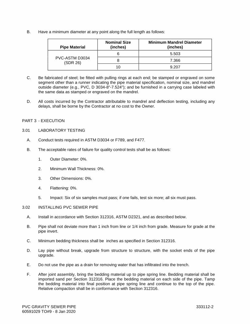
PVC GRAVITY SEWER PIPE 333112-2 60591029 TO#9 - 8 Jan 2020
B. Have a minimum diameter at any point along the full length as follows:
Pipe Material Nominal Size
(inches) Minimum Mandrel Diameter
(inches)
PVC-ASTM D3034 (SDR 26)
6 5.503
8 7.366
10 9.207
C. Be fabricated of steel; be fitted with pulling rings at each end; be stamped or engraved on some segment other than a runner indicating the pipe material specification, nominal size, and mandrel outside diameter (e.g., PVC, D 3034-8"-7.524"); and be furnished in a carrying case labeled with the same data as stamped or engraved on the mandrel.
D. All costs incurred by the Contractor attributable to mandrel and deflection testing, including any delays, shall be borne by the Contractor at no cost to the Owner.
PART 3 - EXECUTION
3.01 LABORATORY TESTING
A. Conduct tests required in ASTM D3034 or F789, and F477.
B. The acceptable rates of failure for quality control tests shall be as follows:
1. Outer Diameter: 0%.
2. Minimum Wall Thickness: 0%.
3. Other Dimensions: 0%.
4. Flattening: 0%.
5. Impact: Six of six samples must pass; if one fails, test six more; all six must pass.
3.02 INSTALLING PVC SEWER PIPE
A. Install in accordance with Section 312316, ASTM D2321, and as described below.
B. Pipe shall not deviate more than 1 inch from line or 1/4 inch from grade. Measure for grade at the pipe invert.
C. Minimum bedding thickness shall be inches as specified in Section 312316.
D. Lay pipe without break, upgrade from structure to structure, with the socket ends of the pipe upgrade.
E. Do not use the pipe as a drain for removing water that has infiltrated into the trench.
F. After joint assembly, bring the bedding material up to pipe spring line. Bedding material shall be imported sand per Section 312316. Place the bedding material on each side of the pipe. Tamp the bedding material into final position at pipe spring line and continue to the top of the pipe. Relative compaction shall be in conformance with Section 312316.

PVC GRAVITY SEWER PIPE 333112-3 60591029 TO#9 - 8 Jan 2020
G. Then place bedding material to 1 foot above the top of the pipe and compact to the same relative compaction as in the pipe zone per Section 312316. The remainder of the trench backfill shall be native material, installed per Section 312316.
H. Do not use hydro-hammers to compact bedding or backfill.
3.03 INSTALLING LATERALS
A. Each wye branch fitting shall have its barrel diameter equal to the diameter of the sanitary sewer main and the spur (or branch) diameter as indicated in the drawings. Do not place wye branches within 5 feet of any structure.
B. Install wye fittings so that the outlet branch is inclined upward at an angle of 45 degrees. Plug wye branch fittings that are to be left unconnected with a stopper or plug. Join laterals to wye branch fittings at the sanitary sewer main by eighth bends. Eighth bends and quarter bends are a part of lateral sewer line.
C. End of the lateral shall be at least 3 feet below the existing or proposed grade of the ground at existing structure to be served or as called for in the drawings.
D. Bed laterals the same as the sewer main into which they connect.
E. Plug laterals with stopper in the socket of the last joint. Seal stopper in place so that it will withstand the internal pressure during the test for leakage and so that it may be removed without damage to the socket.
F. Mark the location of each lateral by chiseling a letter "S" 1 1/2 inches high on the top of the curb. If the terminal point of the lateral is more than 8 feet beyond the curb line or curb improvements do not exist, provide and install a 4-inch by 4-inch by 3-foot 0-inch stake extending 2 inches above the ground and placed at the end of the connection.
3.04 INSTALLING PIPE AT MANHOLES AND STRUCTURES
A. Place a 2-foot PVC length of pipe of the same inside diameter as the adjoining pipe at the inlet and outlet to each manhole or structure. Use one of the following methods:
1. Directly cast a manhole coupling into the manhole base. Provide rubber-ring gasket in the coupling.
2. Stretch a rubber-ring gasket around the pipe to serve as a water stop when cast into the structure wall.
B. Do not cast pipe bells into manholes or structures. Cut off the bell so that no recess or offset appears on the exposed face from the inside wall of the pipe to the outside wall of the pipe. The pipe shall have a plain end, flush with the inside wall of the manhole or structure, or as shown in the drawings.
3.05 TESTING FOR DEFECTS OF INSTALLED PIPE
Following placement and compaction of backfill and prior to placing permanent pavement, ball and mandrel the pipe to measure for obstructions (excessive deflections, joint offsets, and lateral pipe intrusions).
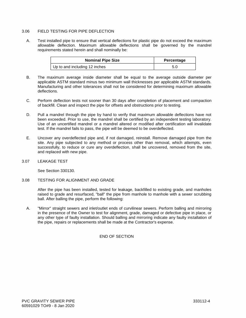
PVC GRAVITY SEWER PIPE 333112-4 60591029 TO#9 - 8 Jan 2020
3.06 FIELD TESTING FOR PIPE DEFLECTION
A. Test installed pipe to ensure that vertical deflections for plastic pipe do not exceed the maximum allowable deflection. Maximum allowable deflections shall be governed by the mandrel requirements stated herein and shall nominally be:
Nominal Pipe Size Percentage
Up to and including 12 inches 5.0
B. The maximum average inside diameter shall be equal to the average outside diameter per applicable ASTM standard minus two minimum wall thicknesses per applicable ASTM standards. Manufacturing and other tolerances shall not be considered for determining maximum allowable deflections.
C. Perform deflection tests not sooner than 30 days after completion of placement and compaction of backfill. Clean and inspect the pipe for offsets and obstructions prior to testing.
D. Pull a mandrel through the pipe by hand to verify that maximum allowable deflections have not been exceeded. Prior to use, the mandrel shall be certified by an independent testing laboratory. Use of an uncertified mandrel or a mandrel altered or modified after certification will invalidate test. If the mandrel fails to pass, the pipe will be deemed to be overdeflected.
E. Uncover any overdeflected pipe and, if not damaged, reinstall. Remove damaged pipe from the site. Any pipe subjected to any method or process other than removal, which attempts, even successfully, to reduce or cure any overdeflection, shall be uncovered, removed from the site, and replaced with new pipe.
3.07 LEAKAGE TEST
See Section 330130.
3.08 TESTING FOR ALIGNMENT AND GRADE
After the pipe has been installed, tested for leakage, backfilled to existing grade, and manholes raised to grade and resurfaced, "ball" the pipe from manhole to manhole with a sewer scrubbing ball. After balling the pipe, perform the following:
A. "Mirror" straight sewers and inlet/outlet ends of curvilinear sewers. Perform balling and mirroring in the presence of the Owner to test for alignment, grade, damaged or defective pipe in place, or any other type of faulty installation. Should balling and mirroring indicate any faulty installation of the pipe, repairs or replacements shall be made at the Contractor's expense.
END OF SECTION

GENERAL PIPING REQUIREMENTS 400500-1 60591029 TO#9 - 8 Jan 2020
SECTION 400500 GENERAL PIPING REQUIREMENTS
PART 1 - GENERAL
1.01 DESCRIPTION
This section describes general requirements for selecting piping materials; selecting the associated bolts, nuts, and gaskets for flanges for the various piping services in the project; and miscellaneous piping items.
1.02 SUBMITTALS
A. Submit shop drawings in accordance with the Special Provisions.
B. Submit affidavit of compliance with referenced standards (e.g., AWWA, ANSI, ASTM, etc.).
C. Submit certified copies of mill test reports for bolts and nuts, including coatings if specified. Provide recertification by an independent domestic testing laboratory for materials originating outside of the United States.
D. Submit manufacturer's data sheet for gaskets supplied showing dimensions and bolting recommendations.
1.03 DEFINITIONS OF BURIED AND EXPOSED PIPING
A. Buried piping is piping buried in the soil, commencing at the wall or beneath the slab of a structure. Where a coating is specified, provide the coating up to the structure wall. Unless detailed otherwise, coating shall penetrate wall no less than 1 inch. Piping encased in concrete is considered to be buried. Do not coat encased pipe.
B. Exposed piping is piping in any of the following conditions or locations:
1. Above ground.
2. Inside buildings, vaults, or other structures.
3. In underground concrete trenches or galleries.
1.04 PIPING SERVICE
Piping service is determined by the fluid conveyed, regardless of the pipe designation. For example, pipes designated "Air Low Pressure," "Air High Pressure," and "Air" are all considered to be in air service.
PART 2 - MATERIALS
2.01 THREAD FORMING FOR STAINLESS STEEL BOLTS
Form threads by means of rolling, not cutting or grinding.
GENERAL PIPING REQUIREMENTS 400500-2 60591029 TO#9 - 8 Jan 2020
2.02 BOLTS AND NUTS FOR FLANGES FOR STEEL AND DUCTILE-IRON PIPING (SPECIFICATION SECTION 402040)
A. Bolts and nuts for Class 125 or 150 flanges (including AWWA C207, Class D) located indoors and in vaults and structures shall be carbon steel, ASTM A307, Grade B, hot-dipped galvanized per ASTM F2329.
B. Bolts and nuts for buried or submerged Class 125 or 150 flanges shall be Type 316 stainless steel conforming to ASTM A193, Grade B8M for bolts and ASTM A194, Grade 8M for nuts.
C. Fit shall be Classes 2A and 2B per ASME B1.1 when connecting to cast-iron valves having body bolt holes.
D. Bolts used in flange insulation kits shall conform to ASTM A193 (Grade B7). Nuts shall conform to ASTM A194 (Grade 2H).
E. Provide washers for each nut. Washers shall be of the same material as the nuts.
2.03 BOLTS AND NUTS FOR FLANGES FOR PVC PIPE (SPECIFICATION SECTION 402092)
A. Bolts and nuts for flanges located indoors, outdoors above ground, and in vaults and structures shall be carbon steel, ASTM A307, Grade B, hot-dipped galvanized per ASTM F2329.
B. Bolts and nuts for buried and submerged flanges and flanges located outdoors above ground or in vaults and structures shall be Type 316 stainless steel conforming to ASTM A193, Grade B8M for bolts and ASTM A194, Grade 8M for nuts.
2.04 MOLDABLE FILLER TAPE FOR PIPE SURFACE TRANSITION AREAS
A. Filler tape shall be a 100% solids mastic-like butyl-rubber filler designed to fill and smooth the transition areas between adjacent coating surfaces such as step-down weld areas, surface irregularities beneath heat-shrink sleeves, pipefittings, and exothermic welds for cathodic protection bonding wire connections. Characteristics:
1. Thickness per ASTM D1000: 1/8 inch minimum.
2. Peel adhesion to primed pipe: 300 ounces per inch minimum.
3. Elongation: 600% minimum.
B. Products: Tapecoat “Moldable Sealant,” Polyken No. 939 Filler Tape, or equal.
PART 3 - EXECUTION
3.01 INSTALLING PIPE SPOOLS IN CONCRETE
Install pipes in walls and slabs before placing concrete. See Sections 030500 and 400762.
3.02 RAISED FACE AND FLAT FACE FLANGES
Where a raised face flange connects to a flat-faced flange, remove the raised face of the flange.
GENERAL PIPING REQUIREMENTS 400500-3 60591029 TO#9 - 8 Jan 2020
3.03 INSTALLING ABOVEGROUND OR EXPOSED PIPING
A. Provide pipe hangers and supports as detailed in the drawings.
B. Install pipe without springing, forcing, or stressing the pipe or any adjacent connecting valves or equipment.
3.04 INSTALLING FLANGED PIPING
A. Set pipe with the flange bolt holes straddling the pipe horizontal and vertical centerline. Install pipe without springing, forcing, or stressing the pipe or any adjacent connecting valves or equipment. Before bolting up, align flange faces to the design plane within 1/16 inch per foot measured across any diameter. Align flange bolt holes within 1/8-inch maximum offset.
B. Inspect each gasket to verify that it is the correct size, material, and type for the specified service and that it is clean and undamaged. Examine bolts or studs, nuts, and washers for defects such as burrs or cracks and rust and replace as needed.
C. Clean flanges by wire brushing before installing flanged fittings. Clean flange bolts and nuts by wire brushing, lubricate carbon steel bolts with oil and graphite, and tighten nuts uniformly and progressively.
D. Bolt lengths shall extend completely through their nuts. Any that fail to do so shall be considered acceptably engaged if the lack of complete engagement is not more than one thread.
E. Do not use more than one gasket between contact faces in assembling a flanged joint.
F. Tighten the bolts to the manufacturer’s specifications, using the recommended cross bolt pattern in multiple steps of increasing torque, until the final torque requirements are achieved. Do not over torque.
G. If flanges leak under pressure testing, loosen or remove the nuts and bolts, reset or replace the gasket, reinstall or retighten the bolts and nuts, and retest the joints. Joints shall be watertight.
3.05 INSTALLATION OF STAINLESS STEEL BOLTS AND NUTS
Prior to assembly, coat threaded portions of stainless steel bolts and nuts with lubricant.
END OF SECTION

GENERAL PIPING REQUIREMENTS 400500-4 60591029 TO#9 - 8 Jan 2020
THIS PAGE INTENTIONALLY LEFT BLANK
PRESSURE TESTING OF PIPING 400515-1 60591029 TO#9 - 8 Jan 2020
SECTION 400515 PRESSURE TESTING OF PIPING
PART 1 - GENERAL
1.01 DESCRIPTION
This section specifies the cleaning and hydrostatic and leakage testing of pressure piping for pumping stations, and raw sewage force mains.
1.02 RELATED WORK SPECIFIED ELSEWHERE
A. Manual, Check, and Process Valves: 400520.
1.03 SUBMITTALS
A. Submit shop drawings in accordance with the Special Provisions.
B. Submit test bulkhead locations and design calculations, pipe attachment details, and methods to prevent excessive pipe wall stresses.
C. Submit the test records to the Owner's Representative upon completion of the testing.
1.04 TEST PRESSURES
Test pressures are shown in Paragraph 3.08 A.
1.05 TESTING RECORDS
Provide records of each piping installation during the testing. These records shall include:
A. Date and times of test.
B. Identification of pipeline, or pipeline section tested or retested.
C. Identification of pipeline material.
D. Identification of pipe specification.
E. Test fluid.
F. Test pressure at low point in pipeline or pipeline section.
G. Remarks: Leaks identified (type and location), types of repairs, or corrections made.
H. Certification by Contractor that the leakage rate measured conformed to the specifications.

PRESSURE TESTING OF PIPING 400515-2 60591029 TO#9 - 8 Jan 2020
PART 2 - MATERIALS
2.01 MANUAL AIR-RELEASE VALVES FOR BURIED PIPING
Provide temporary manual air-release valves for pipeline test. Construct the pipe outlet in the same manner as for a permanent air valve and after use, seal with a blind flange, pipe cap, or plug and coat the same as the adjacent pipe.
2.02 TEST BULKHEADS
Design and fabricate test bulkheads per Section VIII of the ASME Boiler and Pressure Vessel Code. Materials shall comply with Part UCS of said code. Design pressure shall be at least 2.0 times the specified test pressure for the section of pipe containing the bulkhead. Limit stresses to 70% of yield strength of the bulkhead material at the bulkhead design pressure. Include air-release and water drainage connections.
2.03 TESTING FLUID
A. Testing fluid shall be water shown in the following subsections.
B. For potable water pipelines, obtain and use only potable water for hydrostatic testing.
C. Submit request for use of water from waterlines of Owner 48 hours in advance.
D. The Contractor may obtain the water from the Owner at no charge.
2.04 TESTING EQUIPMENT
Provide calibrated pressure gauges, pipes, bulkheads, pumps, chart recorder, and meters to perform the hydrostatic testing.
PART 3 - EXECUTION
3.01 TESTING PREPARATION
A. Pipes shall be in place, backfilled, and anchored before commencing pressure testing.
B. Conduct pressure tests on exposed and aboveground piping after the piping has been installed and attached to the pipe supports, hangers, anchors, expansion joints, valves, and meters.
C. For buried piping, the pipe may be partially backfilled and the joints left exposed for inspection during an initial leakage test. Perform the final pressure test, however, after completely backfilling and compacting the trench.
D. Provide any temporary piping needed to carry the test fluid to the piping that is to be tested. After the test has been completed and demonstrated to comply with the specifications, disconnect and remove temporary piping. Do not remove exposed vent and drain valves at the high and low points in the tested piping; remove any temporary buried valves and cap the associated outlets. Plug taps or connections to the existing piping from which the test fluid was obtained.
E. Provide temporary drain lines needed to carry testing fluid away from the pipe being tested. Remove such temporary drain lines after completing the pressure testing.
F. Prior to starting the test, the Contractor shall notify the Owner's Representative.

PRESSURE TESTING OF PIPING 400515-3 60591029 TO#9 - 8 Jan 2020
3.02 INITIAL PIPELINE FILLING FOR HYDROSTATIC TESTING
Maximum rate of filling shall not cause water velocity in pipeline to exceed 1 fps. Filling may be facilitated by removing automatic air valves and releasing air manually.
3.03 TESTING NEW PIPE WHICH CONNECTS TO EXISTING PIPE
Prior to testing new pipelines that are to be connected to existing pipelines, isolate the new line from the existing line by means of test bulkheads, spectacle flanges, or blind flanges. After successfully testing the new line, remove test bulkheads or flanges and connect to the existing piping.
3.04 HYDROSTATIC TESTING OF ABOVEGROUND OR EXPOSED PIPING
A. Open vents at high points of the piping system to purge air while filling the pipe with water. Venting during system filling may also be provided by temporarily loosening flanges.
B. Subject the piping system to the test pressure indicated. Maintain the test pressure for a minimum of four hours. Examine joints, fittings, valves, and connections for leaks. The piping system shall show zero leakage or weeping. Correct leaks and retest until zero leakage is obtained.
3.05 HYDROSTATIC TESTING OF BURIED PIPING
A. Where any section of the piping contains concrete thrust blocks or encasement, do not perform the pressure test until at least 10 days after placing the concrete. When testing mortar-lined or PVC piping, fill the pipe to be tested with water and allow it to soak for at least 48 hours to absorb water before conducting the pressure test.
B. Apply and maintain the test pressure by means of a positive displacement hydraulic force pump.
C. Maintain the test pressure for the following duration by restoring it whenever it falls an amount of 5 psi:
Pipe Diameter (inches)
Hours
18 and less 4
20 to 36 8
Greater than 36 24
D. After the test pressure is reached, use a meter to measure the additional water added to maintain the pressure. This amount of water is the loss due to leakage in the piping system. The allowable leakage volume is defined by the formula
L = HND(P)1/2
C
in which:
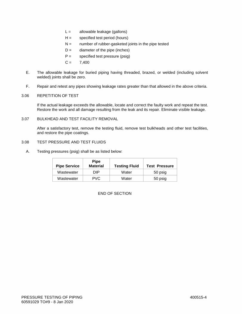
PRESSURE TESTING OF PIPING 400515-4 60591029 TO#9 - 8 Jan 2020
L = allowable leakage (gallons)
H = specified test period (hours)
N = number of rubber-gasketed joints in the pipe tested
D = diameter of the pipe (inches)
P = specified test pressure (psig)
C = 7,400
E. The allowable leakage for buried piping having threaded, brazed, or welded (including solvent welded) joints shall be zero.
F. Repair and retest any pipes showing leakage rates greater than that allowed in the above criteria.
3.06 REPETITION OF TEST
If the actual leakage exceeds the allowable, locate and correct the faulty work and repeat the test. Restore the work and all damage resulting from the leak and its repair. Eliminate visible leakage.
3.07 BULKHEAD AND TEST FACILITY REMOVAL
After a satisfactory test, remove the testing fluid, remove test bulkheads and other test facilities, and restore the pipe coatings.
3.08 TEST PRESSURE AND TEST FLUIDS
A. Testing pressures (psig) shall be as listed below:
Pipe Service Pipe
Material Testing Fluid Test Pressure
Wastewater DIP Water 50 psig
Wastewater PVC Water 50 psig
END OF SECTION
MANUAL, CHECK, AND PROCESS VALVES 400520-1 60591029 TO#9 - 8 Jan 2020
SECTION 400520 MANUAL, CHECK, AND PROCESS VALVES
PART 1 - GENERAL
1.01 DESCRIPTION
This section includes materials, testing, and installation of manually operated valves, check valves, and process valves including gate, knife gate, butterfly, ball, hose bibbs, globe, angle, needle, eccentric plug, lubricated plug, nonlubricated plug, diaphragm, check, pinch, solenoid, pet cocks, mud valves, vacuum breakers, deluge valves, flap valves, balancing valves, gauge valves, instrument valve manifolds, and telescoping valves.
1.02 RELATED WORK SPECIFIED ELSEWHERE
A. Connections to Existing Buried Pipelines: 020130.
B. Painting and Coating: 099000.
C. Cold-Applied Wax Tape Coating: 099752.
D. Polyethylene Sheet Encasement (AWWA C105): 099754.
E. Fusion-Bonded Epoxy Linings and Coatings: 099761.
F. General Piping Requirements: 400500.
G. Pressure Testing of Piping: 400515.
1.03 SUBMITTALS
A. Submit shop drawings in accordance with the Special Provisions.
B. Submit manufacturer's catalog data and detail construction sheets showing all valve parts. Describe each part by material of construction, specification (such as AISI, ASTM, SAE, or CDA), and grade or type.
C. Show valve dimensions including laying lengths. Show port sizes. Show dimensions and orientation of valve actuators, as installed on the valves. Show location of internal stops for gear actuators. State differential pressure and fluid velocity used to size actuators. For worm-gear actuators, state the radius of the gear sector in contact with the worm and state the handwheel diameter.
D. Show valve linings and coatings. Submit manufacturer's catalog data and descriptive literature.
E. Submit a report verifying that the valve interior linings and exterior coatings have been tested for holidays and lining thickness. Describe test results and repair procedures for each valve. Do not ship valves to project site until the reports have been returned by the Owner's Representative and marked "Resubmittal not required."
F. For butterfly and eccentric plug valves, show the clear diameter or size of the port. Show the actual area of the port as a percentage of the area as calculated for the nominal valve size.
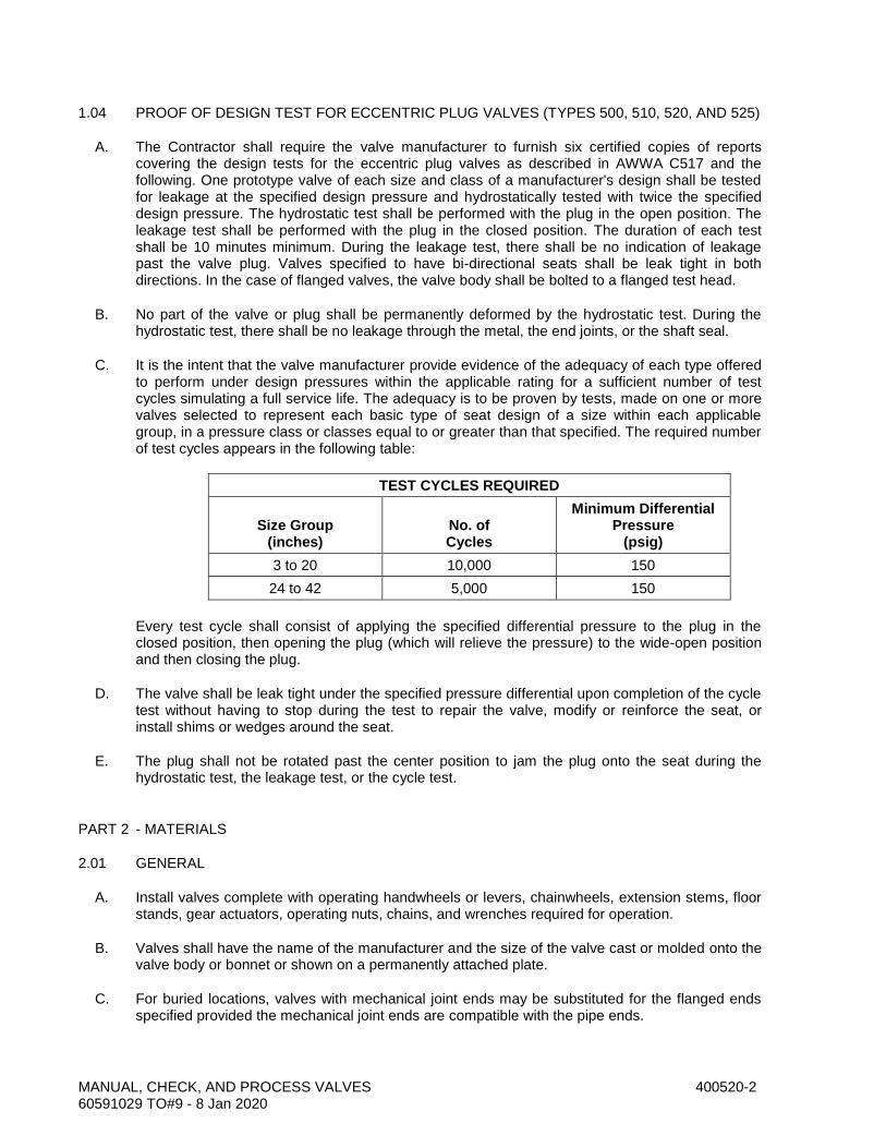
MANUAL, CHECK, AND PROCESS VALVES 400520-2 60591029 TO#9 - 8 Jan 2020
1.04 PROOF OF DESIGN TEST FOR ECCENTRIC PLUG VALVES (TYPES 500, 510, 520, AND 525)
A. The Contractor shall require the valve manufacturer to furnish six certified copies of reports covering the design tests for the eccentric plug valves as described in AWWA C517 and the following. One prototype valve of each size and class of a manufacturer's design shall be tested for leakage at the specified design pressure and hydrostatically tested with twice the specified design pressure. The hydrostatic test shall be performed with the plug in the open position. The leakage test shall be performed with the plug in the closed position. The duration of each test shall be 10 minutes minimum. During the leakage test, there shall be no indication of leakage past the valve plug. Valves specified to have bi-directional seats shall be leak tight in both directions. In the case of flanged valves, the valve body shall be bolted to a flanged test head.
B. No part of the valve or plug shall be permanently deformed by the hydrostatic test. During the hydrostatic test, there shall be no leakage through the metal, the end joints, or the shaft seal.
C. It is the intent that the valve manufacturer provide evidence of the adequacy of each type offered to perform under design pressures within the applicable rating for a sufficient number of test cycles simulating a full service life. The adequacy is to be proven by tests, made on one or more valves selected to represent each basic type of seat design of a size within each applicable group, in a pressure class or classes equal to or greater than that specified. The required number of test cycles appears in the following table:
TEST CYCLES REQUIRED
Size Group
(inches)
No. of Cycles
Minimum Differential Pressure
(psig)
3 to 20 10,000 150
24 to 42 5,000 150
Every test cycle shall consist of applying the specified differential pressure to the plug in the closed position, then opening the plug (which will relieve the pressure) to the wide-open position and then closing the plug.
D. The valve shall be leak tight under the specified pressure differential upon completion of the cycle test without having to stop during the test to repair the valve, modify or reinforce the seat, or install shims or wedges around the seat.
E. The plug shall not be rotated past the center position to jam the plug onto the seat during the hydrostatic test, the leakage test, or the cycle test.
PART 2 - MATERIALS
2.01 GENERAL
A. Install valves complete with operating handwheels or levers, chainwheels, extension stems, floor stands, gear actuators, operating nuts, chains, and wrenches required for operation.
B. Valves shall have the name of the manufacturer and the size of the valve cast or molded onto the valve body or bonnet or shown on a permanently attached plate.
C. For buried locations, valves with mechanical joint ends may be substituted for the flanged ends specified provided the mechanical joint ends are compatible with the pipe ends.
MANUAL, CHECK, AND PROCESS VALVES 400520-3 60591029 TO#9 - 8 Jan 2020
2.02 VALVE ACTUATORS
A. Provide lever or wrench actuators for exposed valves 8 inches and smaller. For larger valves, provide handwheels.
B. Where manually operated valves (size 4 inches and larger) are installed with their centerlines more than 6 feet 9 inches above the floor, provide chainwheel and guide actuators.
C. Provide 2-inch AWWA operating nuts for buried and submerged valves. Check with client on which size range gear actuators should be provided. Some have preferences.
D. Provide enclosed gear actuators on butterfly, ball, and plug valves 6 inches and larger. Gear actuators for valves 8 through 20 inches shall be of the worm and gear, or of the traveling nut type.
E. Design gear actuators assuming that the differential pressure across the plug, gate, or disc is equal to the test pressure of the connecting piping unless otherwise required in the detailed valve specifications. Size actuators using a minimum safety factor of 1.5 for valves in open/close service and 2.0 in modulating service.
F. Gear actuators shall be enclosed, oil lubricated, with seals provided on shafts to prevent entry of dirt and water into the actuator. Gear actuators for valves located above ground or in vaults and structures shall have handwheels. The actuators for valves in exposed service shall contain a dial indicating the position of the valve disc or plug. Gear actuators for buried or submerged valves shall have 2-inch-square AWWA operating nuts.
G. For buried or submerged service or valves installed in buried vaults, provide watertight shaft seals and watertight valve and actuator cover gaskets. Provide totally enclosed actuators designed for buried or submerged service.
H. Traveling nut and worm and gear actuators shall be of the totally enclosed design so proportioned as to permit operation of the valve under full differential pressure rating of the valve with a maximum pull of 80 pounds on the handwheel or crank. Provide stop limiting devices in the actuators in the open and closed positions. Actuators shall be of the self-locking type to prevent the disc or plug from creeping. Design actuator components between the input and the stop-limiting devices to withstand without damage a pull of 200 pounds for handwheel or chainwheel actuators and an input torque of 300 foot-pounds for operating nuts when operating against the stops.
I. Handwheel diameters for traveling nut actuators shall not exceed 8 inches for valves 12 inches and smaller.
J. Self-locking worm gear shall be a one-piece design of gear bronze material (ASTM B427; or ASTM B84, Alloy C86200), accurately machine cut. Actuators for eccentric and lubricated plug valves may use ductile-iron gears provided the gearing is totally enclosed with spring-loaded rubber lip seals on the shafts. The worm shall be hardened alloy steel (ASTM A322, Grade G41500 or G41400; or ASTM A148, Grade 105-85), with thread ground and polished. Support worm-gear shaft at each end by ball or tapered roller bearings. The reduction gearing shall run in a proper lubricant. The handwheel diameter shall be no more than twice the radius of the gear sector in contact with the worm. Worm-gear actuators shall be Limitorque Model HBC, EIM Series W, or equal.
K. Design actuators on buried valves to produce the required torque on the operating nut with a maximum input of 150 foot-pounds.
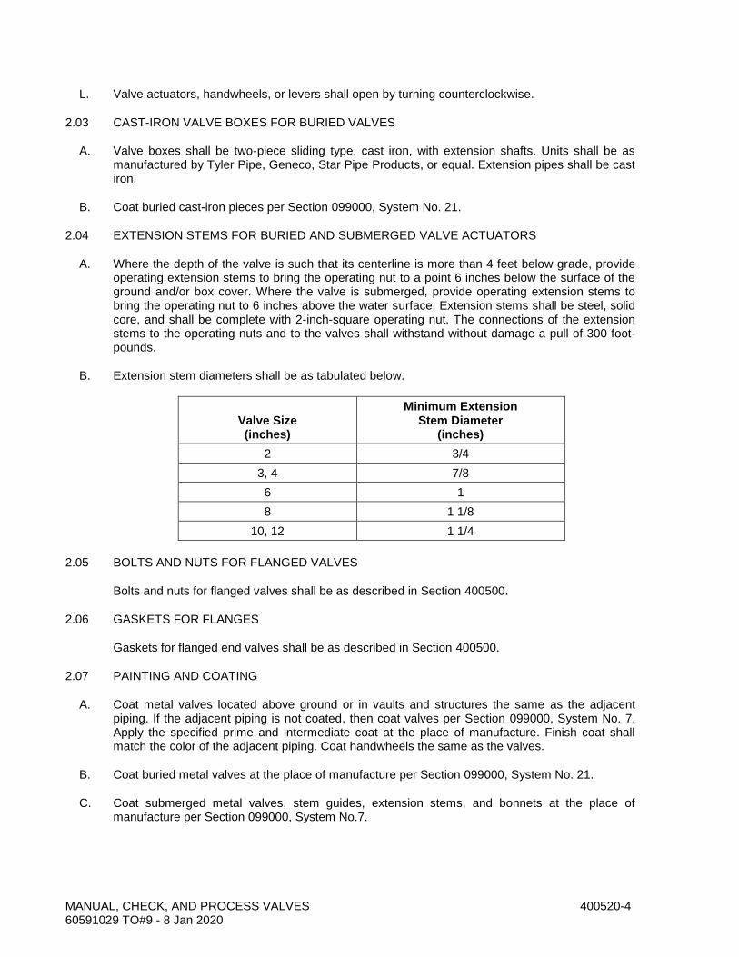
MANUAL, CHECK, AND PROCESS VALVES 400520-4 60591029 TO#9 - 8 Jan 2020
L. Valve actuators, handwheels, or levers shall open by turning counterclockwise.
2.03 CAST-IRON VALVE BOXES FOR BURIED VALVES
A. Valve boxes shall be two-piece sliding type, cast iron, with extension shafts. Units shall be as manufactured by Tyler Pipe, Geneco, Star Pipe Products, or equal. Extension pipes shall be cast iron.
B. Coat buried cast-iron pieces per Section 099000, System No. 21.
2.04 EXTENSION STEMS FOR BURIED AND SUBMERGED VALVE ACTUATORS
A. Where the depth of the valve is such that its centerline is more than 4 feet below grade, provide operating extension stems to bring the operating nut to a point 6 inches below the surface of the ground and/or box cover. Where the valve is submerged, provide operating extension stems to bring the operating nut to 6 inches above the water surface. Extension stems shall be steel, solid core, and shall be complete with 2-inch-square operating nut. The connections of the extension stems to the operating nuts and to the valves shall withstand without damage a pull of 300 foot-pounds.
B. Extension stem diameters shall be as tabulated below:
Valve Size (inches)
Minimum Extension Stem Diameter
(inches)
2 3/4
3, 4 7/8
6 1
8 1 1/8
10, 12 1 1/4
2.05 BOLTS AND NUTS FOR FLANGED VALVES
Bolts and nuts for flanged valves shall be as described in Section 400500.
2.06 GASKETS FOR FLANGES
Gaskets for flanged end valves shall be as described in Section 400500.
2.07 PAINTING AND COATING
A. Coat metal valves located above ground or in vaults and structures the same as the adjacent piping. If the adjacent piping is not coated, then coat valves per Section 099000, System No. 7. Apply the specified prime and intermediate coat at the place of manufacture. Finish coat shall match the color of the adjacent piping. Coat handwheels the same as the valves.
B. Coat buried metal valves at the place of manufacture per Section 099000, System No. 21.
C. Coat submerged metal valves, stem guides, extension stems, and bonnets at the place of manufacture per Section 099000, System No.7.

MANUAL, CHECK, AND PROCESS VALVES 400520-5 60591029 TO#9 - 8 Jan 2020
D. Line the interior metal parts of metal valves 4 inches and larger, excluding seating areas and bronze and stainless steel pieces, per Section 099000, System No. 7. Apply lining at the place of manufacture.
E. Test the valve interior linings and exterior coatings at the factory with a low-voltage (22.5 to 80 volts, with approximately 80,000-ohm resistance) holiday detector, using a sponge saturated with a 0.5% sodium chloride solution. The lining shall be holiday free.
F. Measure the thickness of the valve interior linings per Section 099000. Repair areas having insufficient film thickness per Section 099000.
2.08 PACKING, O-RINGS, AND GASKETS
Unless otherwise stated in the detailed valve specifications, packing, O-rings, and gaskets shall be one of the following non asbestos materials:
A. Teflon.
B. Kevlar aramid fiber.
C. Acrylic or aramid fiber bound by nitrile. Products: Garlock "Bluegard," Klinger "Klingersil C4400," or equal.
D. Buna-N (nitrile).
2.09 RUBBER SEATS
Rubber seats shall be made of a rubber compound that is resistant to free chlorine and monochloramine concentrations up to 10 mg/L in the fluid conveyed.
2.10 VALVES
A. Plug Valves:
1. Plug and Seating Design for Eccentric Plug Valves (Types 500, 510, 515, 520, and 525):
Eccentric plug valves shall comply with AWWA C517 and the following. Provide a rectangular or circular plug design, with an associated rectangular or round seat. Provide bidirectional seating design. The valve shall seat with the rated pressure both upstream and downstream of the closed plug. Provide geared actuators sized for bidirectional operation.
2. For Types 500, 510, 515, 520, and 525 eccentric plug valves, the metallic portion of the plug shall be one-piece design and shall be without external reinforcing ribs which result in there being a space between the rib and the main body of the plug through which water can pass. Valves shall be repackable without any disassembly of valve or actuator. The valve shall be capable of being repacked while under the design pressure in the open position. Nowhere in the valve or actuators shall the valve shaft be exposed to iron on iron contact. Sleeve bearings shall be stainless steel in valve sizes 20 inches and smaller and bronze or stainless steel in valve sizes 24 inches and larger. Provide enclosed worm-gear actuators for valves 6 inches and larger.
3. Rubber compounds shall have less than 2% volume increase when tested in accordance with ASTM D471 after being immersed in distilled water at a temperature of 73.4°F ±2°F for 70 hours.

MANUAL, CHECK, AND PROCESS VALVES 400520-6 60591029 TO#9 - 8 Jan 2020
4. Type 510—Eccentric Plug Valves 2 Through 12 Inches:
Eccentric plug valves, 4 through 12 inches, shall be nonlubricated type. Minimum pressure rating shall be 175 psi. Bodies shall be cast iron per ASTM A126, Class B. Ends shall be flanged, Class 125 per ASME B16.1. Plugs shall be cast iron (ASTM A126, Class B), or ductile iron (ASTM A536, Grade 65-45-12) with Buna-N facing. Design plugs to seat over a pressure range of 5 to 25 psi0 to 5 psi. Valve body seats shall be Type 304 or 316 stainless steel or have a raised welded-in overlay at least 1/8-inch thick of not less than 90% nickel. Body cap screws and bolts and nuts shall be Type 316 stainless steel. Packing shall be butadiene-filled Teflon. Provide 100% port area. Valves shall be DeZurik Figure 118 PEC, Clow F-5412, Val-Matic “Cam-Centric,” or equal.
B. Check Valves:
1. Type 750—Rubber Flapper Swing Check Valves (3 Through 24 Inches):
Valves shall consist of body, flapper, and bolted cover. Operating pressure shall be at least 175 psi at a temperature of 212°F. Valve seat shall be set at an angle of 35 to 45 degrees to the centerline of the pipe. Ends shall be flanged, ASME B16.1, Class 125. Body and cover shall be cast iron (ASTM A48, Class 30, or ASTM A126, Class B). Flapper shall consist of a steel disk insert and a steel bar hinge covered with EPDM bonded to the metal pieces. Provide O-ring seal bonded onto the disk. Provide 1/8-inch-thick EPDM lining in valve body. Lining shall have a hardness of 50 to 60 durometer, Shore A. Cover bolts shall be Type 316 stainless steel. Products: APCO Series 100R, Val-Matic Series 500, or equal.
C. Tideflex Check Valve:
1. Series TF-2
a. Match pipe size shown on drawings
b. Elastomeric construction
c. Material EPDM
d. 316 Stainless steel mounting band
2. 2-inch maximum cracking pressure.
PART 3 - EXECUTION
3.01 VALVE SHIPMENT AND STORAGE
A. Provide flanged openings with metal closures at least 3/16-inch thick, with elastomer gaskets and at least four full-diameter bolts. Install closures at the place of valve manufacture prior to shipping. For studded openings, use all the nuts needed for the intended service to secure closures. Alternatively, ship flanged valves 3 inches and smaller in separate sealed cartons or boxes.
B. Provide threaded openings with steel caps or solid-shank steel plugs. Do not use nonmetallic (such as plastic) plugs or caps. Install caps or plugs at the place of valve manufacture prior to

MANUAL, CHECK, AND PROCESS VALVES 400520-7 60591029 TO#9 - 8 Jan 2020
shipping. Alternatively, ship valves having threaded openings or end connections in separate sealed cartons or boxes.
C. Store resilient seated valves in sealed polyethylene plastic enclosures with a minimum of one package of desiccant inside. Store resilient seated valves in the open or unseated position. Valves with adjustable packing glands shall have the packing gland loosened prior to storage. Inspect valves at least once per week, replace desiccant if required and repair damaged storage enclosures. Do not store valves with resilient seats near electric motors or other electrical equipment.
D. Inspect valves on receipt for damage in shipment and conformance with quantity and description on the shipping notice and order. Unload valves carefully to the ground without dropping. Use forklifts or slings under skids. Do not lift valves with slings or chain around operating shaft, actuator, or through waterway. Lift valves with eyebolts or rods through flange holes or chain hooks at ends of valve parts.
E. Protect the valve and actuators from weather and the accumulation of dirt, rocks, and debris. Do not expose rubber seats to sunlight or ozone for more than 30 days. Also, see the manufacturer’s specific storage instructions.
F. Make sure flange faces, joint sealing surfaces, body seats, and disc seats are clean. Check the bolting attaching the actuator to the valve for loosening in transit and handling. If loose, tighten firmly. Open and close valves having manual or power actuators to make sure the valve operates properly and that stops or limit switches are correctly set so that the valve seats fully. Close valve before installing.
3.02 FACTORY PRESSURE TESTING
A. Hydrostatically test the valve pressure-containing parts at the factory per the valve specification or per the referenced standard. If no testing requirement is otherwise specified or described in the referenced standards, then test with water for 30 minutes minimum at a pressure of 1.5 times the rated pressure but not less than 20 psig. Test shall show zero leakage. If leaks are observed, repair the valve and retest. If dismantling is necessary to correct valve deficiencies, then provide an additional operational test and verify that the valve components function.
B. The chloride content of liquids used to test austenitic stainless steel materials shall not exceed 50 ppm. To prevent deposition of chlorides as a result of evaporative drying, remove residual liquid from tested parts at the conclusion of the test.
3.03 INSTALLING VALVES—GENERAL
A. Remove covers over flanged openings and plugs from threaded openings, after valves have been placed at the point to which the valves will be connected to the adjacent piping. Do not remove valves from storage cartons or boxes until they are ready to be installed.
B. Handle valves carefully when positioning, avoiding contact or impact with other equipment, vault or building walls, or trench walls.
C. Clean valve interiors and adjacent piping of foreign material prior to making up valve to pipe joint connection. Prepare pipe ends and install valves in accordance with the pipe manufacturer’s instructions for the joint used. Do not deflect pipe-valve joint. Do not use a valve as a jack to pull pipe into alignment. The installation procedure shall not result in bending of the valve/pipe connection with pipe loading.
MANUAL, CHECK, AND PROCESS VALVES 400520-8 60591029 TO#9 - 8 Jan 2020
D. Make sure valve ends and seats are clean. Check exposed bolting for loosening in transit and handling and tighten to manufacturer’s recommendations. Open and close the valve to make sure it operates properly and that stops or limit switches are correctly set so that the vane, ball, gate, needle, diaphragm, disc, plug, or other seating element seats fully. Close the valve before installing. Check coatings for damage and repair. Handle valves carefully when positioning, avoiding contact or impact with other equipment or structures.
E. Prior to assembly, coat threaded portions of stainless steel bolts and nuts with lubricant.
3.04 INSTALLING EXPOSED VALVES
A. Unless otherwise indicated in the drawings, install valves in horizontal runs of pipe having centerline elevations 4 feet 6 inches or less above the floor with their operating stems vertical. Install valves in horizontal runs of pipe having centerline elevations between 4 feet 6 inches and 6 feet 9 inches above the floor with their operating stems horizontal.
B. Install valves on vertical runs of pipe that are next to walls with their stems horizontal, away from the wall. Valves on vertical runs of pipe that are not located next to walls shall be installed with their stems horizontal, oriented to facilitate valve operation.
3.05 INSTALLING BURIED VALVES
A. Connect the valve, coat the flanges, apply tape wrapping or polyethylene encasement, and place and compact the backfill to the height of the valve stem.
B. Place block pads under the extension pipe to maintain the valve box vertical during backfilling and repaving and to prevent the extension pipe from contacting the valve bonnet.
C. Mount the upper slip pipe of the extension in midposition and secure with backfill around the extension pipe. Pour the concrete ring allowing a depression so the valve box cap will be flush with the pavement surface.
3.06 FIELD COATING BURIED VALVES
A. Coat flanges of buried valves and the flanges of the adjacent piping, and the bolts and nuts of flanges and mechanical joints, per Section 099000, System No. 24.
B. Wrap buried metal valves smaller than 6 inches with cold-applied wax tape per Section 099752.
C. Wrap buried metal valves 6 inches and larger with polyethylene sheet per Section 099754in two layers of polyethylene conforming to AWWA C105, 8 mils in thickness each. Pass the two sheets of polyethylene under the valve and the coated flanges or joints with the connecting pipe and draw the sheets around the valve body, the valve bonnet, and the connecting pipe. Secure the sheets with plastic adhesive tape about the valve stem below the operating nut and about the barrel of the connecting pipe to prevent the entrance of soil. Fold overlaps twice and tape. Backfill the valve with care to avoid damaging the polyethylene.
3.07 ASSEMBLING JOINTS
A. Bolt holes of flanged valves shall straddle the horizontal and vertical centerlines of the pipe run to which the valves are attached. Clean flanges by wire brushing before installing flanged valves. Clean flange bolts and nuts by wire brushing, lubricate threads with oil and graphite, and tighten nuts uniformly and progressively. If flanges leak under pressure testing, loosen or remove the nuts and bolts, reseat or replace the gasket, reinstall or retighten the bolts and nuts, and retest the joints. Joints shall be watertight.

MANUAL, CHECK, AND PROCESS VALVES 400520-9 60591029 TO#9 - 8 Jan 2020
B. Clean threaded joints by wire brushing or swabbing. Apply Teflon joint compound or Teflon tape to pipe threads before installing threaded valves. Joints shall be watertight.
C. Install lug-type valves with separate hex head machine bolts at each bolt hole and each flange (two bolts per valve bolt hole).
D. Install grooved-end couplings for valves in accordance with Section 400500.
3.08 INSTALLING EXTENSION STEM GUIDE BRACKETS
Install at 6- to 8-foot centers. Provide at least two support brackets for stems longer than 10 feet, with one support near the bottom of the stem and one near the top.
3.09 FIELD INSTALLATION OF GEAR ACTUATOR
Provide the actuator manufacturer's recommended lubricating oil in each actuator before commencing the field testing.
3.10 VALVE FIELD TESTING
A. Test valves for leakage at the same time that the connecting pipelines are hydrostatically tested. See Section 400515 for pressure testing requirements. Protect or isolate any parts of valves, actuators, or control and instrumentation systems whose pressure rating is less than the pressure test. Valves shall show zero leakage. Repair or replace any leaking valves and retest.
B. Operate manual valves through three full cycles of opening and closing. Valves shall operate from full open to full close without sticking or binding. Do not backfill buried valves until after verifying that valves operate from full open to full closed. If valves stick or bind, or do not operate from full open to full closed, repair or replace the valve and repeat the tests.
C. Gear actuators shall operate valves from full open to full close through three cycles without binding or sticking. The pull required to operate handwheel- or chainwheel-operated valves shall not exceed 80 pounds. The torque required to operate valves having 2-inch AWWA nuts shall not exceed 150 ft-lbs. If actuators stick or bind or if pulling forces and torques exceed the values stated previously, repair or replace the actuators and repeat the tests. Operators shall be fully lubricated in accordance with the manufacturer's recommendations prior to operating.
END OF SECTION

MANUAL, CHECK, AND PROCESS VALVES 400520-10 60591029 TO#9 - 8 Jan 2020
THIS PAGE INTENTIONALLY LEFT BLANK

FLEXIBLE PIPE COUPLINGS AND EXPANSION JOINTS 400722-1 60591029 TO#9 - 8 Jan 2020
SECTION 400722 FLEXIBLE PIPE COUPLINGS AND EXPANSION JOINTS
PART 1 - GENERAL
1.01 DESCRIPTION
This section includes materials and installation of flexible gasketed sleeve-type compression pipe couplings for ductile-iron pipe; and expansion joints 4 inches in diameter and smaller for PVC, flexible expansion joints; and couplings for connecting different pipe materials.
1.02 RELATED WORK SPECIFIED ELSEWHERE
A. Painting and Coating: 099000.
B. Cold-Applied Wax Tape Coating: 099752.
C. Polyethylene Sheet Encasement (AWWA C105): 099754.
D. Fusion-Bonded Epoxy Linings and Coatings: 099761.
E. General Piping Requirements: 400500.
F. Pressure Testing of Piping: 400515.
G. Wall Pipes, Seep Rings, and Penetrations: 400762.
1.03 SUBMITTALS
A. Submit shop drawings in accordance with the Special Provisions.
B. Submit manufacturer's catalog data on flexible pipe couplings and expansion joints. Show manufacturer's model or figure number for each type of coupling or joint for each type of pipe material for which couplings and joints are used. Show coatings.
C. Submit manufacturer's recommended torques to which the coupling bolts shall be tightened for the flexible gasketed sleeve-type compression pipe couplings.
D. Show materials of construction by ASTM reference and grade. Show dimensions.
E. Show number, size, and material of construction of tie rods and lugs for each thrust harness on the project.
PART 2 - MATERIALS
2.01 COUPLING SYSTEM DESIGN AND COMPONENT UNIT RESPONSIBILITY
The coupling manufacturer shall furnish the gaskets, bolts, nuts, glands, end rings, and hardware for pipe couplings of all types and shall design these components as an integral system. Design the gaskets for the coupling and appropriately size to provide a watertight seal at the design pressure and temperature. Ship gaskets, bolts, nuts, glands, end rings, and hardware for pipe couplings with the pipe coupling and clearly label indicating the origin of the material, including

FLEXIBLE PIPE COUPLINGS AND EXPANSION JOINTS 400722-2 60591029 TO#9 - 8 Jan 2020
place and date of manufacture. Package the manufacturer's printed installation instructions with each pipe coupling.
2.02 DUCTILE-IRON FLEXIBLE PIPE COUPLINGS
A. Couplings shall have center sleeves and end rings made of ductile iron conforming to AWWA C219, Section 4.
B. Sleeve bolts in exposed service shall be 316 stainless steel per AWWA C219, Section 4.
2.03 FLEXIBLE PIPE COUPLINGS FOR PLAIN-END DUCTILE-IRON PIPE
A. Couplings for pipe 12 inches and smaller shall be cast iron, Dresser Style 253 or 253 long sleeve, Smith-Blair Type 441, Baker Series 228, or equal.
B. Couplings for pipe larger than 12 inches shall be cast iron or steel, Dresser Style 38 or 253, Smith-Blair Style 411, Baker Series 228, or equal.
2.04 TRANSITION COUPLINGS
Couplings for connecting different pipes having different outside diameters shall be steel: Dresser Style 62 or 162, Smith-Blair Series 413, Baker Series 212 or 220, or equal. Couplings shall have an internal full circumference ring pipe stop at the midpoint of the coupling. Inside diameter of coupling pipe stop shall equal inside diameter of smaller diameter pipe.
2.05 FLANGED COUPLING ADAPTERS FOR CAST- AND DUCTILE-IRON PIPE
A. Adapters for cast- and ductile-iron pipe 12 inches and smaller shall be cast iron: Dresser Style 127, Smith-Blair Series 912, or equal.
B. Adapters for cast- and ductile-iron pipe larger than 12 inches shall be steel: Dresser Style 128, Smith-Blair Type 913, or equal.
C. Flange ends shall match the flange of the connecting pipe; see detail piping specifications.
2.06 BOLTS AND NUTS FOR FLANGES
See Section 400500.
PART 3 - EXECUTION
3.01 SHIPMENT AND STORAGE OF FLEXIBLE PIPE COUPLINGS, DISMANTLING JOINTS, EXPANSION JOINTS, AND FLEXIBLE HOSE CONNECTORS
A. Inspect on receipt for damage in shipment and conformance with quantity and description on the shipping notice and order. Unload carefully to the ground without dropping. Do not load or unload by inserting forklift tines or lifting chains inside the waterway. Use nonmetallic slings, padded chains, or padded forklift tines to lift items. Lift with eyebolts or rods through flange holes or chain hooks at ends.
B. Protect from weather and the accumulation of dirt, rocks, and debris. Do not expose rubber seats to sunlight or ozone for more than 30 days. Also, see the manufacturer’s specific storage instructions.
FLEXIBLE PIPE COUPLINGS AND EXPANSION JOINTS 400722-3 60591029 TO#9 - 8 Jan 2020
C. Make sure flange faces, joint sealing surfaces, body seats, and disc seats are clean.
3.02 INSTALLATION OF FLEXIBLE PIPE COUPLINGS, SEGMENTED SLEEVE COUPLINGS, DISMANTLING JOINTS, AND EXPANSION JOINTS
A. Clean oil, scale, rust, and dirt from pipe ends. Clean gaskets in flexible pipe couplings before installing.
B. Do not spring flanges or ends of connecting piping into position. Separately work connecting piping system into position to bring the piping flanges or ends into alignment with the matching coupling flanges or joints. Do not move couplings to achieve piping alignment.
C. Line up pipe flange bolt holes with coupling or joint flange bolt holes within 1/16 inch maximum offset from the center of the bolt hole to permit insertion of bolts without applying any external force to the piping.
D. Flange face separation shall be within the gasket spacing ±1/16 inch. Use only one gasket per flanged connection.
E. Lubricate bolt threads with graphite and oil prior to installation.
F. Thoroughly clean contact surfaces of gaskets and pipe ends of flexible pipe couplings just prior to assembly for a distance equal to center-sleeve length plus 2 inches. Install flexible pipe couplings such that the center sleeves are centered over the gap between the ends of the pipes being joined. Install centerline gaps per AWWA C219, Table 5 unless otherwise indicated. Install harnessed flexible pipe couplings in straight-run piping such that 50% of the total travel of the center sleeve or permissible centerline gap is available for expansion and 50% of the travel is available for contraction. In assembling the bolted or studded harnesses of flexible pipe couplings, tighten the nuts gradually and equally at diametrically opposite sides until snug. Do not misalign the harness bolts or studs. Tighten such that bolts or studs carry equal loads. Do not use wrenches or power fastening tools to tighten the nuts.
3.03 PAINTING AND COATING
A. Coat buried flexible pipe couplings (including joint harness assemblies), transition couplings, segmented sleeve couplings, and flanged coupling adapters per Section 099000, System No. 21 Coat buried bolt threads, tie bolt threads, and nuts per Section 099000, System No. 24 Then wrap the couplings with cold-applied wax tape per Section 099752 and with polyethylene wrap per Section 099754.
B. Coat flexible pipe couplings (including joint harness assemblies), transition couplings, segmented sleeve couplings, and flanged coupling adapters located indoors, in vaults and structures, and above ground with the same coating system as specified for the adjacent pipe. If the adjacent pipe is not coated, coat couplings per Section 099000, System No. 10 per Section 099000. Apply prime coat at factory.
C. Line carbon steel and iron flexible pipe couplings and segmented sleeve couplings per Section 099000, System No. 7.
D. Alternatively, line and coat carbon steel and iron flexible pipe couplings and segmented sleeve couplings with fusion-bonded epoxy per Section 099761.
FLEXIBLE PIPE COUPLINGS AND EXPANSION JOINTS 400722-4 60591029 TO#9 - 8 Jan 2020
3.04 HYDROSTATIC TESTING
Hydrostatically test flexible pipe couplings, expansion joints, segmented sleeve couplings, and expansion compensators in place with the pipe being tested. Test in accordance with Section 400515.
END OF SECTION

WALL PIPES, SEEP RINGS, AND PENETRATIONS 400762-1 60591029 TO#9 - 8 Jan 2020
SECTION 400762 WALL PIPES, SEEP RINGS, AND PENETRATIONS
PART 1 - GENERAL
1.01 DESCRIPTION
This section includes materials, installation, and testing of steel, cast-iron, and ductile-iron wall pipes and sleeves (including wall collars and seepage rings) and penetrations.
1.02 RELATED WORK SPECIFIED ELSEWHERE
A. General Concrete Construction: 030500.
B. Painting and Coating: 099000.
C. Fusion-Bonded Epoxy Linings and Coatings: 099761.
D. General Piping Requirements: 400500.
1.03 SUBMITTALS
A. Submit shop drawings in accordance with the Special Provisions.
B. Submit detail drawings for fabricated steel or cast-iron wall and floor pipes and sleeves, wall flanges, seep rings, and sealing materials. Show dimensions and wall thicknesses.
C. Show flange sizes and the appropriate ANSI or AWWA flange dimensional standard where flanged end wall pipes or penetrations are used.
D. Show grooved-end dimensions and AWWA grooved-end dimensional standard where grooved-end wall pipes or penetrations are used.
E. List coating systems to be applied, manufacturer, and dry thickness of coatings. Call out coatings where coatings are to be applied.
F. List materials of construction, with ASTM material reference and grade.
G. Submit manufacturer’s instructions for installing rubber annular hydrostatic sealing devices.
PART 2 - MATERIALS
2.01 GENERAL
A. Use cast-iron, ductile-iron, or fabricated steel wall sleeves when containing rubber annular hydrostatic sealing devices through which piping passes.
B. Use only cast-iron or ductile-iron wall pipes when connecting to cast-iron and ductile-iron pipe.
C. Cast-iron flanges shall conform to ASME B16.1, Class 125 or 250, to match the flange on the connecting pipe.
D. See Section 400500 for flange bolts and gaskets.

WALL PIPES, SEEP RINGS, AND PENETRATIONS 400762-2 60591029 TO#9 - 8 Jan 2020
2.02 CAST-IRON OR DUCTILE-IRON WALL PIPES AND SLEEVES
A. Provide cast- or ductile-iron wall pipes with ends as shown in the drawings for connection to adjacent cast-iron and ductile-iron pipe or for containing pipes where they pass through concrete walls, ceilings, and floor slabs. Provide seepage ring on wall pipes and sleeves passing through concrete walls and slabs that are to be watertight. Locate collars such that the collar is at the center of the wall or floor slab, unless otherwise shown in the drawings.
B. Wall pipes and sleeves shall be of the following types:
1. Pipe or sleeve with integrally cast seep ring.
2. Pipe or sleeve with shrink-fit steel collar attached.
3. Pipe or sleeve with steel collar halves bottomed in a groove provided in the pipe or sleeve.
C. Minimum wall thickness for pipes and sleeves having integrally cast seep rings shall be as shown in the following table:
Pipe or Sleeve Size (inches)
Minimum Wall Thickness (inches)
3 0.48
4 0.52
6 0.55
8 0.60
10 0.68
D. Minimum wall thickness of pipes or sleeves having shrink-fit collars shall be special Class 52. Cut shrink-fit collars from a 1/4-inch-thick steel ring. Attach the collar to a cast-iron or ductile-iron pipe or sleeve by heating the steel collar and allowing it to shrink over the pipe at the necessary location. Provide an epoxy bond (Keysite 740 or 742 or Scotchkote 302) between the pipe and collar. Sandblast the area of the pipe to be epoxy coated per SSPC SP-10.
E. Wall pipes or sleeves having steel collar halves bottomed in a groove shall be ductile iron Special Class 54 minimum unless otherwise shown. Wall flanges shall consist of 1/4-inch-thick steel seep ring halves for pipes through 24-inch and 3/8-inch-thick halves for pipe 30 inches and larger, bottomed in a groove provided on the pipe. The pipe groove shall be machine cut to a depth of 1/16 to 5/64 inch to provide a press fit for the seep ring. Seep ring halves shall be welded together after fit into groove but shall not be welded to pipe. Seep rings shall be sealed completely around the pipe with silicon sealant manufactured by Dow-Corning No. 790, General Electric Silpruf, or equal.
F. The material used in cast- or ductile-iron wall flanges, wall sleeves, and wall penetrations shall conform to ASTM A395, A436, A536, A48 (Class 35), or A126 (Class B).
2.03 RUBBER ANNULAR HYDROSTATIC SEALING DEVICES
A. Rubber annular hydrostatic sealing devices shall be of the modular mechanical type, utilizing interlocking synthetic rubber links shaped to continuously fill the annular space between the pipe sleeve and the passing pipe. Assemble links to form a continuous rubber belt around the pipe, with a pressure plate under each bolthead and nut.
B. Materials of construction shall be as follows:

WALL PIPES, SEEP RINGS, AND PENETRATIONS 400762-3 60591029 TO#9 - 8 Jan 2020
Compound Material
Pressure plate Delrin plastic or reinforced nylon polymer carbon steel
Bolts and nuts for links Type 303 or 316 stainless steel
Sealing element EPDM rubber
C. The size of the wall sleeve needed to accommodate the passing pipe shall be as recommended by the rubber annular seal manufacturer.
D. Provide centering blocks in 25% of the sealing elements on pipelines larger than 12 inches in diameter.
E. The rubber annular hydrostatic sealing devices shall be Link Seal as manufactured by Thunderline Corporation; Innerlynx as manufactured by Advance Products & Systems, Inc.; or equal.
2.04 BOLTS, NUTS, AND GASKETS FOR FLANGED-END WALL PIPES
See Section 400500.
2.05 POLYETHYLENE FOAM FILLER FOR PIPE PENETRATIONS
Packing foam shall be an extruded closed-cell polyethylene foam rod, such as Minicel backer rod, manufactured by Industrial Systems Department, Plastic Products Group of Hercules, Inc., Middletown, Delaware; Ethafoam, as manufactured by Dow Chemical Company, Midland, Michigan; or equal. The rod shall be 1/2 inch larger in diameter than the annular space.
2.06 POLYURETHANE SEALANT FOR PIPE PENETRATIONS
Sealant shall be multipart, polyurethane sealant, to cure at ambient temperature, for continuous immersion in water. Install as recommended by the manufacturer. Products: SIKA Sikaflex 2C or equal.
2.07 PAINTING AND COATING
A. Line and coat sleeves and pipes with fusion-bonded epoxy per Section 099761
B. Coat penetrations and sleeves exposed, above ground, or in vaults and structures in accordance with Section 099000, System No. 10 unless fusion-bonded epoxy coatings are shown in the drawings or specified elsewhere.
C. Coat buried sleeves and penetrations per Section 099000, System No. 21 with fusion-bonded epoxy per Section 099761.
PART 3 - EXECUTION
3.01 LOCATION OF PIPES AND SLEEVES
A. Provide a wall or floor pipe where shown in the drawings and wherever piping passes through walls or floors of tanks or channels in which the water surface is above the pipe penetration.

WALL PIPES, SEEP RINGS, AND PENETRATIONS 400762-4 60591029 TO#9 - 8 Jan 2020
B. Provide a floor sleeve where shown in the drawings and wherever plastic pipe, steel, or stainless steel pipe 3 inches and smaller or stainless steel or copper tubing passes through a floor or slab. Provide a rubber annular sealing device in the annular space between the sleeve and the passing pipe or tubing.
C. Where wall sleeves are installed in which water or soil is on one or both sides of the channel or wall, provide two rubber annular seals (one at each end of the sleeve).
D. Where pipes pass through walls or slabs and no sleeves or wall or floor pipe with seep ring is provided, pack the annular space with polyethylene foam filler and fill the ends of the penetration with 2 inches of elastomeric sealant on both sides of the structure.
3.02 INSTALLATION IN EXISTING CONCRETE WALLS AND SLABS
Core drill holes 1 to 2 inches larger in diameter than the outside diameter of the wall flange or collar. Install wall pipe and collar assembly axially aligned with the piping to which it will be connected or will contain. Pack the void space between the sleeve and concrete with grout. See Section 030500 for grouting specification.
3.03 INSTALLATION IN NEW CONCRETE WALLS AND SLABS
Install wall pipes and sleeves in walls before placing concrete. Do not allow any portion of the pipe or sleeve to touch any of the reinforcing steel. Install wall pipe or sleeve and collar assembly axially aligned with the piping to which it will be attached or will contain. Provide supports to prevent the pipe or sleeve from displacing or deforming while the concrete is being poured and is curing.
3.04 INSTALLATION OF WALL PIPES HAVING FLANGED END CONNECTIONS
A. Check alignment before grouting in place or pouring concrete. Realign if the sleeve is not properly aligned.
B. Install flanged end wall sleeves or penetrations with bolt holes of the end flanges straddling the horizontal and vertical centerlines of the sleeve.
3.05 QUALIFICATIONS OF WELDERS
Welder qualifications shall be in accordance with AWS D1.1.
3.06 INSTALLATION OF RUBBER ANNULAR HYDROSTATIC SEALING DEVICES
Install in accordance with the manufacturer’s instructions.
3.07 FIELD TESTING
Check each wall penetration for leakage at the time the hydraulic structure is tested for leakage. Penetrations shall show zero leakage.
END OF SECTION

DUCTILE-IRON PIPE 402040-1 60591029 TO#9 - 8 Jan 2020
SECTION 402040 DUCTILE-IRON PIPE
PART 1 - GENERAL
1.01 DESCRIPTION
This section describes materials, testing, and installation of ductile-iron pipe and fittings.
1.02 RELATED WORK SPECIFIED ELSEWHERE
A. Painting and Coating: 099000.
B. Cold-Applied Wax Tape Coating: 099752.
C. Polyethylene Sheet Encasement (AWWA C105): 099754.
D. Fusion-Bonded Epoxy Linings and Coatings: 099761.
E. Trenching, Backfilling, and Compacting: 312316.
F. General Piping Requirements: 400500.
G. Pressure Testing of Piping: 400515.
H. Wall Flanges, Seep Rings, and Penetrations: 400762.
I. Flexible Pipe Couplings and Expansion Joints: 400722.
1.03 SUBMITTALS
A. Submit shop drawings in accordance with the Special Provisions.
B. Provide an affidavit of compliance with standards referenced in this specification, e.g., AWWA C151. Submit copy of report of pressure tests for qualifying the designs of all sizes and types of AWWA C153 fittings that are being used in the project. The pressure test shall demonstrate that the minimum safety factor described in AWWA C153, Section 5.5 is met.
C. Provide the following information:
1. Lining thickness.
2. Wall thickness.
3. Show deflections at push-on and mechanical joints.
4. Submit joint and fitting details and manufacturer’s data sheets.
D. Submit calculations and test data proving that the proposed restrained joint arrangement can transmit the required forces with a minimum safety factor of 1.5.
E. Submit certificate that cement for mortar lining complies with ASTM C150, designating type.
F. Submit test report on physical properties of rubber compound used in the gaskets.

DUCTILE-IRON PIPE 402040-2 60591029 TO#9 - 8 Jan 2020
G. Submit drawing or manufacturer's data sheet showing flange facing, including design of facing serrations.
H. Submit weld procedure specification, procedure qualification record, and welder's qualifications prior to any welding to ductile-iron pipe.
PART 2 - MATERIALS
2.01 PIPE
Pipe shall be cast ductile (nodular) iron, conforming to AWWA C151.
2.02 PIPE MARKING
Plainly mark each length of straight pipe. Mark the spigot end of restrained joint pipe to show clearly the required depth of insertion into the bell.
2.03 PIPE WALL THICKNESS
A. Minimum wall thickness for pipe having push-on or mechanical joints, restrained joints, plain ends, or cast flange ends shall be Special Class 50, unless otherwise shown in the drawings.
B. Minimum wall thickness for pipe having threaded flanges shall be Special Class 53 or Pressure Class 350.
C. Minimum pipe wall thickness required for corporation stops and tapped outlets shall be in accordance with Table A.1 of AWWA C151 for three full threads for design pressures up to 250 psi and four full threads for design pressures over 250 to 350 psi.
2.04 FITTINGS
A. Fittings 48 inches and smaller shall conform to AWWA C110 with a minimum pressure rating of 250 psi. Material shall be ductile iron. Flanges shall be flat faced.
B. Mechanical joint fittings conforming to AWWA C153 may be used in lieu of AWWA C110 fittings. Mechanical joint ductile-iron fittings 18 through 48 inches conforming to AWWA C110 (except for laying length) with a minimum pressure rating of 250 psi may also be used.
C. Material for fittings with welded-on bosses shall have a Charpy notch impact value of minimum 10 ft-lbs under the conditions defined in AWWA C151. Test completed welds by the liquid penetrant method per ASTM E165.
2.05 FLANGES
A. Flanges shall be solid back, Class 125 per AWWA C115. Flanges on pipe shall be either cast or threaded. Material shall be ductile iron.
B. Flanged pipe and fittings shall be shop fabricated, not field fabricated. Threaded flanges shall comply with AWWA C115. Flanges shall be individually fitted and machine tightened in the shop, then machined flat and perpendicular to the pipe barrel. Flanges shall be backfaced parallel to the face of flange. Prior to assembly of the flange onto the pipe, apply a thread compound to the threads to provide a leak-free connection. There shall be zero leakage through the threads at a hydrostatic test pressure of 250 psi without the use of the gasket.

DUCTILE-IRON PIPE 402040-3 60591029 TO#9 - 8 Jan 2020
2.06 PIPE LINING AND COATING
A. Pipe and fittings shall be lined and coated with fusion-bonded epoxy per Section 099761.
B. Maintain a moist environment inside the lined pipe and fittings by sealing the ends with polyethylene sheet.
C. Loose areas of cement-mortar lining are not acceptable. Remove and reconstruct lining in areas where quality is defective, such as sand pockets, voids over sanded areas, blisters, drummy areas, cracked areas, and thin spots. Repair longitudinal cracks in excess of 1/32 inch in width or where crack extends to metal with epoxy. Repair all cracks larger than 1/16 inch with epoxy.
2.07 GASKETS FOR FLANGES
See Section 400500.
2.08 GASKETS FOR MECHANICAL, PUSH-ON, AND RESTRAINED JOINTS
Synthetic rubber in accordance with AWWA C111.
2.09 BOLTS AND NUTS FOR FLANGES
See Section 400500.
2.10 JOINTS
A. Joints in buried piping shall be of the restrained type per AWWA C111 except where flanged joints are required to connect to valves, meters, and other equipment. AWWA C110 fittings for these restrained joints 12 inches and smaller are not available.
B. Restrained joints for piping 6 inches and larger shall be American Cast Iron Pipe "Lok-Ring" or "Flex-Ring," U.S. Pipe "TR-Flex," or equal. Weldments for restrained joints shall be tested by the liquid penetrant method per ASTM E165. Restrained joints for field closures shall be “Megalug” by EBAA Iron.
C. Restrained joints in 4-inch-diameter buried piping shall be American Cast Iron Pipe Company “Fast-Grip,” U.S. Pipe Field-lok gasket within Tyton joint pipe and fittings, or equal. Joint restraint shall be certified to four times rated pressure of 200 psi by Factory Mutual.
D. Where thrust restraint is called for in the drawings, provide pipe with restrained joints capable of transmitting 1.5 times the thrust, as calculated by the following equation:
T = 1.5 * (0.785 * P * D2)
where:
P = Pressure class of pipe in psi. D = Outside diameter of pipe in inches. T = Thrust in pounds.

DUCTILE-IRON PIPE 402040-4 60591029 TO#9 - 8 Jan 2020
PART 3 - EXECUTION
3.01 DELIVERY, UNLOADING, AND TEMPORARY STORAGE OF PIPE AT SITE
A. Limit onsite pipe storage to a maximum of one week.
B. Use unloading and installation procedures that avoid cracking of the lining. If necessary, use plastic sheet bulkheads to close pipe ends and keep cement-mortar lining moist.
C. Deliver the pipe alongside the pipelaying access road over which the pipe trailer-tractors can travel under their own power. Place the pipe in the order in which it is to be installed and secure it from rolling.
D. Do not move pipe by inserting any devices or pieces of equipment into the pipe barrel. Field repair linings damaged by unloading or installation procedures.
3.02 SANITATION OF PIPE INTERIOR
A. During laying operations, do not place tools, clothing, or other materials in the pipe.
B. When pipelaying is not in progress, close the ends of the installed pipe by a child- and vermin-proof plug.
3.03 INSTALLING FLANGED PIPE AND FITTINGS
Install in accordance with Sections 400500. Cut the bore of the gaskets such that the gaskets do not protrude into the pipe when the flange bolts are tightened.
3.04 INSTALLING GROOVED-END PIPE AND FITTINGS
See Section 400500.
3.05 INSTALLING BURIED PIPING
A. Install in accordance with AWWA C600, Section 312316, and as follows.
B. Provide thrust blocks at fittings per Section 312316.
C. Assemble restrained joints per manufacturer's instructions.
3.06 JOINT DEFLECTIONS FOR BURIED PIPE
A. Do not exceed the following deflection angles for unrestrained buried pipe joints:
Pipe Size (inches)
Maximum Deflection (degrees)
Push-On Joint Mechanical Joint
4 4 6 1/2
6 4 5 1/2
8 4 4
10 4 4
B. For restrained joints, do not exceed 80% of the manufacturer's recommended maximum deflections.

DUCTILE-IRON PIPE 402040-5 60591029 TO#9 - 8 Jan 2020
C. Assemble joints in accordance with AWWA C600 and the manufacturer's recommendations.
3.07 INSTALLING ABOVEGROUND OR EXPOSED PIPING
See Section 400500 .
3.08 PAINTING AND COATING
A. Coat pipe located above ground and in vaults and structures per Section 099000, System No. 10 Apply prime coat in the shop before transporting pipe to the jobsite. Apply intermediate and finish coats in the field before installing the pipe, then touch up after installation.
B. Coat buried flanges and buried mechanical and restrained joint bolts, nuts, and glands per Section 099000, System No. 21.
3.09 POLYETHYLENE ENCASEMENT OF BURIED PIPE AND FITTINGS
Wrap buried pipe, fittings, and joints with polyethylene per Section 099754.
3.10 CLEANING PIPE
After interior joints have been pointed and mortar has hardened, sweep pipe clean of all dirt and debris. If hardened mud exists in the pipe, remove with the use of pressurized water hoses.
3.11 FIELD HYDROSTATIC TESTING
Test pressures are shown in Section 400515. Test in accordance with Section 400515.
END OF SECTION

DUCTILE-IRON PIPE 402040-6 60591029 TO#9 - 8 Jan 2020
THIS PAGE INTENTIONALLY LEFT BLANK
PVC DISTRIBUTION PIPE (AWWA C900 AND C909) 402092-1 60591029 TO#9 - 8 Jan 2020
SECTION 402092 PVC DISTRIBUTION PIPE (AWWA C900)
PART 1 - GENERAL
1.01 DESCRIPTION
This section includes materials, installation, and testing of PVC distribution pipe conforming to AWWA C900. Size range is 4 through 12 inches.
1.02 RELATED WORK SPECIFIED ELSEWHERE
A. Painting and Coating: 099000.
B. Cold-Applied Wax Tape Coating: 099752.
C. Polyethylene Sheet Encasement (AWWA C105): 099754.
D. Fusion-Bonded Epoxy Linings and Coatings: 099761.
E. Trenching, Backfilling, and Compacting: 312316.
F. General Piping Requirements: 400500.
G. Pressure Testing of Piping: 400515.
H. Flexible Pipe Couplings and Expansion Joints: 400722.
1.03 SUBMITTALS
A. Submit shop drawings in accordance with the Special Provisions.
B. Provide affidavit of compliance with AWWA C900.
C. Submit fully dimensioned cross-he bell and barrel of the pipe. Show the bell maximum outside diameter in the pressurized area and its minimum wall thickness at the same location.
D. Submit copies of the following manufacturer-required tests conducted on project pipe:
1. Quick-burst strength of pipe and couplings.
2. Flattening resistance of pipe.
3. Record of additional tests after test sample failure.
E. Submit manufacturer's literature of gray iron and ductile-iron fittings including dimensions, thickness, weight, coating, lining, and a statement of inspection and compliance with the acceptance tests of AWWA C110 or C153. Submit copy of report of pressure tests for qualifying the designs of all sizes and types of AWWA C153 fittings that are being used in the project. The pressure test shall demonstrate that the minimum safety factor described in AWWA C153, Section 53-15 is met.
F. Submit outline drawings and materials description of service connection saddles, corporation stops, and pipe plugs.
PVC DISTRIBUTION PIPE (AWWA C900 AND C909) 402092-2 60591029 TO#9 - 8 Jan 2020
PART 2 - MATERIALS
2.01 IPE
AWWA C900, rubber-ring gasket bell end or plain end with elastomeric gasket coupling, DR 18, cast iron equivalent outside diameter, material cell classification 12454-B per ASTM D1784.
2.02 FITTINGS
A. Fittings shall conform to AWWA C110 with a minimum pressure rating of 250 psi. Size bells specifically for outside diameter of cast-iron equivalent PVC pipe including rubber-ring retaining groove.
B. Mechanical joint fittings conforming to AWWA C153 may be used in lieu of AWWA C110 fittings.
2.03 LINING AND COATING FOR FITTINGS
A. Line and coat fittings with fusion-bonded epoxy per Section 099761.
2.04 FLANGES
Flanges on outlets of fittings shall be Class 125 per ASME B16.1.
2.05 GASKETS FOR FLANGES
See Section 400500.
2.06 BOLTS AND NUTS FOR FLANGES
See Section 400500.
2.07 RESTRAINED JOINTS
Provide restrained joints where indicated in the drawings. Restrained joints shall be provided by restraining systems that incorporate a series of machined serrations on the inside diameter of a restraint ring to provide positive restraint. Restraining systems shall meet or exceed the requirements of UNI-B-13-94 and ASTM F1674 and the following:
A. Restraint devices for bell-and-spigot joints shall consist of a split restraint ring installed on the spigot, connected to a solid backup ring seated behind the bell.
B. Restraint devices for connection to ductile-iron mechanical joints shall consist of a split restraint ring installed behind the ductile-iron fitting follower gland and gasket and shall retain the full deflection capability of the joint.
C. The split restraint ring shall be machined to match the outside diameter of the pipe, provide full 360-degree support around the barrel of the pipe, and shall incorporate a series of machined serrations for gripping the outside surface of the pipe. The serrations shall be uniform and extend the full circumference of the clamp. The ring shall also incorporate a positive means of avoiding applying excessive clamping force to the pipe.
D. Materials used in the restraint device shall be ductile iron conforming to ASTM A536, Grade 60-42-12 or 65-45-12.

PVC DISTRIBUTION PIPE (AWWA C900 AND C909) 402092-3 60591029 TO#9 - 8 Jan 2020
E. T-bolts, studs, and connecting hardware shall be high-strength, low alloy material in accordance with AWWA C111.
F. Design restraining devices to have a 2:1 safety factor based on the design strength of the pipe.
G. Restraining devices shall be UNI-Flange Block Buster Series 1300 or 1500, EBAA Iron Series 1600, or equal.
2.08 FLANGED COUPLING ADAPTERS
See Section 400722.
PART 3 - EXECUTION
3.01 PRODUCT MARKING
Legibly mark pipe at 5-foot intervals and each coupling to identify the nominal diameter, the outside diameter base, that is, cast-iron or steel pipe (IPS), the material code for pipe and couplings, the dimension ratio number, AWWA C900, and the seal of the testing agency that verified the suitability of the material for potable water service (NSF in the United States).
3.02 DELIVERY AND TEMPORARY STORAGE OF PIPE
A. Ship, store, and place pipe at the installation site, supporting the pipe uniformly. Avoid scratching the pipe surface. Do not stack higher than 4 feet or with weight on bells. Cover to protect from sunlight.
B. Do not install pipe that is gouged or scratched forming a clear depression.
3.03 PIPE LAYOUT FOR CURVED ALIGNMENT
Pipe lengths may be bent for curved alignment but to no smaller radius curve than the following:
Pipe Diameter (inches)
Minimum Curve Radius (feet)
4 400
6 600
8 800
10 1,000
12 1,200
3.04 HANDLING PIPE
Hoist pipe with mechanical equipment using a cloth belt sling or a continuous fiber rope that avoids scratching the pipe. Do not use a chain. Pipes up to 12 inches in diameter may be lowered by rolling on two ropes controlled by snubbing. Pipes up to 6 inches in diameter may be lifted by hand.
3.05 INSTALLING BURIED PIPING
A. Install in accordance with AWWA C605, Section 312316, and as follows.

PVC DISTRIBUTION PIPE (AWWA C900 AND C909) 402092-4 60591029 TO#9 - 8 Jan 2020
B. When installing pipe in trenches, do not deviate more than 1 inch from line or 1/4 inch from grade. Measure for grade at the pipe invert.
C. Backfill materials in the pipe zone shall be imported sand per Section 312316. Do not add successive layers unless the previous layer is compacted to 90% relative compaction per ASTM D1557.
D. Compact material placed within 12 inches of the outer surface of the pipe by hand tamping only.
E. Compact trench backfill to the specified relative compaction. Do not float pipe. Do not use high-impact hammer-type equipment except where the pipe manufacturer warrants in writing that such use will not damage the pipe.
3.06 ASSEMBLY OF PIPE JOINT
A. The spigot and bell or bell coupling shall be dirt free and slide together without displacing the rubber ring. Lay the pipe section with the bell coupling facing the direction of laying.
B. Insert the rubber ring into the groove in the bell in the trench just before joining the pipes. First clean the groove. Observe the correct direction of the shaped ring. Feel that the ring is completely seated.
C. Lubricate the spigot over the taper and up to the full insertion mark with the lubricant supplied by the pipe manufacturer. If the lubricated pipe end touches dirt, clean the pipe end and reapply lubricant.
D. Insert the spigot into the bell and force it slowly into position.
E. Check that the rubber ring has not left the groove during assembly by passing a feeler gauge around the completed joint.
3.07 WRAPPING FITTINGS AND RESTRAINED JOINT DEVICES
Wrap buried cast-iron fittings and restrained joint devices with wax tape per Section 099752.
3.08 FIELD HYDROSTATIC TESTING
Test pressures are shown in Section 400515. Test in accordance with Section 400515.
END OF SECTION

SUBMERSIBLE RAW WASTEWATER PUMPS 432140-1 60591029 TO#9 - 8 Jan 2020
SECTION 432140 SUBMERSIBLE RAW WASTEWATER PUMPS
PART 1 - GENERAL
1.01 DESCRIPTION
This section includes materials, installation, and testing of submersible raw wastewater pumps designed to operate in a wet well under submerged conditions.
1.02 RELATED WORK SPECIFIED ELSEWHERE
A. Painting and Coating: 099000.
B. Pump Controls: 221329.
1.03 SUBMITTALS
A. Submit shop drawings in accordance with the Special Provisions.
B. Submit dimensional drawings.
C. Submit manufacturer's catalog data and detail drawings showing all pump parts and describe by material of construction, specification (such as AISI, ASTM, SAE, or CDA), and grade or type. Show linings and coatings. Show outline dimensions and weights of pumps, bases, and motors. Submit pump curves from manufacturer's catalog data on which the specified operating points are marked. Show efficiency, brake horsepower, and NPSH required for the selected pump curve for each specified operating point. Show maximum operating speed.
D. Show impeller diameter, eye area, sphere size, and number of vanes.
E. Submit setting drawings. Show anchor bolt layout and anchor bolt dimensions.
F. Submit manufacturer's reports on hydrostatic tests and performance tests.
G. Submit manufacturer's sample form for reporting the performance test results. Submit at least two weeks before the tests. The test form shall contain the data presented in the sample form in Section 6 of ASME PTC 8.2 or ANSI/HI 1.6.
H. Submit manufacturer's certified performance curves for review at least two weeks prior to shipping the units from the factory.
1.04 DEFINITIONS
Terms shall be as defined in ANSI/HI 11.6-2001 and ASME PTC 8.2. If there is a discrepancy in definitions between the two publications, the definitions given in ANSI/HI 11.6-2001 shall govern.
1.05 MANUFACTURER'S SERVICES
Provide equipment manufacturer's services at the jobsite for the minimum labor days listed below, travel time excluded:
A. One labor day for each service listed in the subsection on “Service Conditions” to check the installation and advise during start-up, testing, and adjustment of the pumps.

SUBMERSIBLE RAW WASTEWATER PUMPS 432140-2 60591029 TO#9 - 8 Jan 2020
B. One labor day to instruct the Owner's personnel in the operation and maintenance of the pumps.
PART 2 - MATERIALS
2.01 PUMP DESIGN
A. The Contractor shall assign unit responsibility to the pump supplier for the complete pump system, including motors and cooling system control assembly.
B. Each pump shall be of the vertical, nonclog, single-suction, centrifugal type and shall be suitable for pumping unscreened raw sewage.
C. The pump, with its appurtenances and electric cable, shall be capable of continuous submergence under water without loss of watertight integrity to a minimum depth of 65 feet.
D. Design the casing to withstand a hydrostatic test of at least 150% of the pump discharge pressure (suction pressure plus pump differential pressure) at shutoff.
E. Each pump shall be capable of at least a 5% head increase at normal operating conditions by installing a larger impeller or an impeller of different hydraulic design.
F. Pump curve shall be continuously rising and shall be free of dips and valleys from the design point to the shutoff head. The shutoff head shall be at least of the head that occurs at the design point.
G. The NPSH required shall be at least 5 feet less than the minimum NPSH available at all points on the pump curve up to 120% of the flow at the BEP.
H. Design the pump and its components to operate continuously over a flow range of 50% to 120% of the flow at the BEP.
2.02 DISCHARGE CONNECTIONS
A. Suction and discharge connections shall be flanged, ASME B16.1, Class 125. Flanges shall be flat faced. Bolt holes shall straddle the horizontal and vertical centerlines.
B. The pump shall be automatically connected to the discharge connection elbow when lowered into place and shall be easily removed for inspection or service. Sealing of the pumping unit to the discharge elbow shall be accomplished by a simple linear downward motion of the pump. A sliding guide bracket shall be an integral part of the pump unit. The entire weight of the pump unit shall be guided by no less than two stainless steel guide bars or stainless steel guide wire pressed tightly against the discharge connection elbow. No portion of pump shall bear directly on the floor of the sump.
2.03 POWER SUPPLY
Power supply will be as noted on the drawings.
2.04 VIBRATION AND RESIDUAL UNBALANCE
A. The maximum vibration level shall not exceed that shown in Figure 11.6.16B in ANSI/HI 11.6-2001.

SUBMERSIBLE RAW WASTEWATER PUMPS 432140-3 60591029 TO#9 - 8 Jan 2020
B. Maximum residual unbalance in impellers shall not exceed that shown in Figure 9.6.4.15B in ANSI/HI 9.6.4.
2.05 VOLUTE CASING
Volute casing shall be of a single piece, nonconcentric design with smooth fluid passages at all points to pass any size solids which can pass through the impeller. Casing shall be accurately machined to fit the mechanical seal and suction cover assemblies. Fit the bottom of the volute with a Type 316 or 420 stainless steel or rubber-lined carbon steel replacement wear ring. The volute shall have a discharge nozzle. Provide a 3/4-inch drain with plug in the volute.
2.06 IMPELLER
A. Impeller shall be enclosed type with a maximum of two impeller shall be cast in one piece and shall be statically and dynamically balanced, double-shrouded thrulet with smooth water passage to prevent clogging by stringy or fibrous materials and other matter found in normal raw wastewater applications.
B. Each impeller shall be keyed to the shaft, and the fastening of the impeller to the shaft shall be made by a locking device. The locking device shall be sealed from the liquid by means of an O-ring and covered and secured to the end face of the shaft by a single bolt.
C. Fit each impeller with a replaceable wear ring for pump horsepower and larger to provide sealing between the volute and impeller.
2.07 SHAFTS
A. Pump shaft diameter shall be such that it will not deflect more than 0.002-inch at the mechanical seal face with the largest impeller installed while operating at the maximum pump speed. Tolerance on the shaft diameter shall not exceed 0.002 inch. Dynamic shaft deflection at the stuffing box face shall not exceed 0.002 inch.
B. The first lateral critical speed of the rotating assembly shall be at least 120% of the maximum pump operating speed.
C. Surface finish of the shafts or sleeves through the mechanical seal and at the rubbing contact-bearing housing seals shall not exceed a roughness of 32 microinches.
D. If a carbon steel shaft is used, provide Type 420 stainless steel shaft sleeves having a minimum hardness of 450 Brinell.
2.08 PUMP SEAL
A. Provide each pump with a tandem mechanical shaft seal system. The upper of the tandem set of seals shall operate in an oil chamber located just below the stator housing. This set shall contain one stationary tungsten carbide or cast chromium ring and one positively driven rotating carbon ring functioning as an independent secondary barrier between the pumped liquid and the stator housing. The lower of the tandem set of seals shall function as the primary barrier between the pumped liquid and the stator housing. This set shall consist of a stationary ring and a positively driven rotating ring, both of which shall be tungsten carbide.
B. Each interface shall be held in contact by its own spring system supplemented by external liquid pressures. The seals shall require neither maintenance nor adjustment but shall be easily inspected and replaceable.
SUBMERSIBLE RAW WASTEWATER PUMPS 432140-4 60591029 TO#9 - 8 Jan 2020
C. Shaft seals without positively driven rotating members or conventional double mechanical seals with a common single or double spring acting between the upper and lower units requiring a substantial pressure differential to offset external pressure and effect sealing shall not be considered acceptable or equal to the dual independent seal system specified.
D. The shaft sealing system shall be capable of operating submerged to depths of or pressures equivalent to a minimum of 65 feet. No seal damage shall result from operating the pumping unit out of its liquid environment. The seal system shall not rely upon the pumped media for lubrication.
2.09 OIL CHAMBER
Provide each pump with an oil chamber for the shaft sealing system. Design the oil chamber to assure that air is left in the oil chamber to absorb the expansion of the oil due to temperature variations. The drain and inspection plug, with positive anti-leak seal, shall be easily accessible from the outside.
2.10 BEARINGS
A. Each pump shaft shall rotate on two permanently lubricated bearings. The upper bearing, providing for radial thrust, shall be a single row, roller bearing. The lower bearing shall consist of one double row or two single row angular contact bearing(s) for combined axial and radial loads.
B. Pump bearings shall be of the antifriction type designed to give 40,000 hours minimum life by L-10 calculations at maximum speed and operating load in continuous operation.
2.11 CABLE ENTRY
Each cable entry shall be comprised of a single cylindrical elastomer grommet, flanked by stainless steel washers, all having a close tolerance fit against the cable outside diameter and the entry inside diameter and compressed by the entry body containing a strain relief function, separate from the function of sealing the cable. The assembly shall bear against a shoulder in the pump top. The cable entry system shall utilize one of the two designs specified below.
A. The cable entry junction chamber and motor shall be separated by two terminal boards, which shall isolate the motor interior from foreign material gaining access through the pump top. Both the terminal boards shall be bolted to the interior of the motor housing and sealed by O-rings.
B. Provide cast-iron, pressure-tight cable entry gland, which shall be sealed by a nitrile rubber ring and compression gland. Design the compression gland to conform to the allowable bending radius of the power cable. In addition, cast each individual conductor wire in resin in such a manner to avoid any water leakage into the motor through capillary action, because of external cable damage or other causes.
2.12 MATING SURFACES
A. Machine and fit mating surfaces of major parts with nitrile O-rings where watertight sealing is required. Machining and fitting shall be such that sealing is accomplished by automatic compression in two planes and O-ring contact made on four surfaces, without the requirement of a specific torque limit. Rectangular cross-sectioned gaskets requiring specific torque limits to achieve compression shall not be considered adequate or equal.
B. Tolerances of parts shall be such that they allow replacement of any part without additional machining required to ensure sealing as described above. No secondary sealing compounds, greases, or other devices shall be used.

SUBMERSIBLE RAW WASTEWATER PUMPS 432140-5 60591029 TO#9 - 8 Jan 2020
2.13 COOLING SYSTEM
A. The motor cooling system shall consist of ambient cooling by radiation and convection to the surrounding space and conduction through the pump volute to the pumped fluid. Paragraph below describes the cooling system utilized in Flygt pumps.
B. Pumps equipped with water-cooling system consisting of a water jacket are also acceptable. The water-cooling jacket system shall encircle the stator housing. Provide the water jacket with a separate circulation of the pumped liquid. Cooling water shall enter the cooling jacket by way of the pumping vanes, integral with the impeller design, and exit with the pumping media. Cooling media channels and ports shall be nonclogging by virtue of their dimensions. Provide a separate, clear, external water source for motor cooling as well as lower seal flushing. Alternatively, ambient cooling of the motor may be utilized.
C. Pumps equipped with integral cooling consisting of a pumped ethylene-glycol coolant circulated by means of an impeller on the pump shaft are also acceptable. Provide a cooling jacket and internal pump impeller to circulate the coolant to cool the pump by conduction through the pump volute to the pumped fluid and by radiation and convection to the surrounding space. Alternatively, ambient cooling of the motor may be used when the pump size and duty permits.
2.14 ELECTRIC MOTORS
A. Each pump shall be driven by a vertical, submersible squirrel cage induction motor, shell type design, housed in an air-filled, watertight chamber. The stator winding and stator leads shall be insulated with moisture-resistant Class F insulation which will resist a temperature of 155°C, 40°C ambient plus 115°C rise, and designed for continuous duty, capable of sustaining a minimum of 10 starts per hour.
B. The stator shall be dipped and baked three times in Class F varnish and shall be shrink-fitted into the stator housing. The use of bolts, pins, or other fastening devices requiring penetration of the stator housing shall be rejected.
C. The motor shall be sized to be nonoverloading when the pump is operated at any point on the pump performance characteristic curve drawn through the design point and shall have a minimum service factor of 1.10. Motor service factor shall not be used in satisfying pumping requirement.
D. Equip the stator with three sensors or thermistors embedded in the end coils of the stator winding to monitor stator temperature. Provide one sensor or thermistor in each stator phase, to switch off the unit if a winding temperature of 285°F is exceeded.
E. If the pump manufacturer uses thermistors in the motor windings, the pump manufacturer shall provide the motor winding thermistor relay and any motor bearing thermistor relays and shall arrange for their installation in the pump motor starter. Both relays shall operate in a 120-volt control circuit and have contacts as shown in the electrical drawings. Adjust and arrange relays to properly respond to the thermistors mounted within the pump-motor housing.
F. Each pump motor shall have a sensor system to monitor moisture in the stator cavity and temperature sensors within the motor stator windings. Provide a supervision relay for installation in the pump motor starter to trip an alarm if moisture content indicates a failure of the outer mechanical seal or if high temperature is detected in the stator. Supervision relay system shall be Flygt MiniCAS II or equal.
G. Connect sensors and thermistor relays to the pump motor starter in such a manner that their signal can actuate an alarm or provide for immediate shutdown or both.

SUBMERSIBLE RAW WASTEWATER PUMPS 432140-6 60591029 TO#9 - 8 Jan 2020
2.15 MOTOR CABLES
Pump motor power cables installed shall be made of a Hypalon or Protolon synthetic rubber-jacketed, Type SPC multiconductor cable, suitable for submersible pump applications and heavy mechanical stresses. The power cable shall also be sized according to NEC and ICEA standards and also meet with P-MSHA approval or equivalent. Use a separate Hypalon or Protolon synthetic rubber-jacketed, Type SPC cable for temperature and moisture pilot protection signals. The total length of each cable shall be a minimum of 40 feet.
2.16 MATERIALS OF CONSTRUCTION
A. Materials of construction shall be as listed below:
Component Material Specification
Casing, volute, suction and discharge elbows
Cast iron ASTM A48 Class 35B
Impeller Cast Iron ASTM A48 Class 35B
Shaft Stainless steel AISI 431
Impeller wear ring Cast Iron ASTM A48 Class 35B
Drain and vent plugs Malleable iron ASTM A197
Cap screws, bolts, and nuts Stainless steel AISI Type 316
Any bronze components in contact with water
See paragraph C below
B. Do not construct the impeller wear ring and case wear ring of the same material. Impeller and bowl wear ring materials shall have a minimum Brinell hardness difference of 50 unless both the stationary and the rotating wear surfaces have Brinell hardness numbers of at least 50.
C. Bronze shall have the following chemical characteristics:
Constituent Content
Zinc 7% maximum
Aluminum 2% maximum
Lead 8% maximum
Copper + Nickel + Silicon 83% minimum
2.17 ANCHOR BOLTS, NUTS, AND WASHERS
A. Anchor bolts, nuts, and washers for pumps installed in dry wells shall be stainless steel per Section 050520.
B. Anchor bolts, nuts, and washers for pumps installed in wet wells shall be stainless steel per Section 050520.
2.18 SPARE PARTS
A. Provide the following spare parts for each model or size of pump:
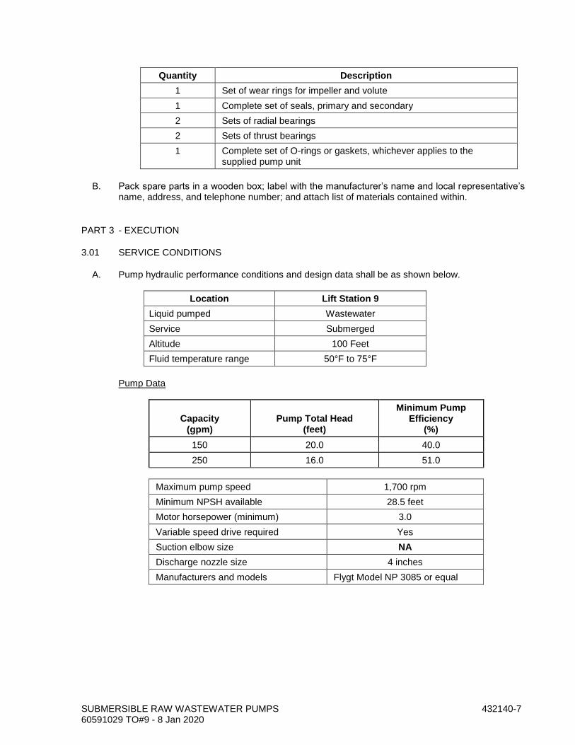
SUBMERSIBLE RAW WASTEWATER PUMPS 432140-7 60591029 TO#9 - 8 Jan 2020
Quantity Description
1 Set of wear rings for impeller and volute
1 Complete set of seals, primary and secondary
2 Sets of radial bearings
2 Sets of thrust bearings
1 Complete set of O-rings or gaskets, whichever applies to the supplied pump unit
B. Pack spare parts in a wooden box; label with the manufacturer’s name and local representative’s name, address, and telephone number; and attach list of materials contained within.
PART 3 - EXECUTION
3.01 SERVICE CONDITIONS
A. Pump hydraulic performance conditions and design data shall be as shown below.
Location Lift Station 9
Liquid pumped Wastewater
Service Submerged
Altitude 100 Feet
Fluid temperature range 50°F to 75°F
Pump Data
Capacity (gpm)
Pump Total Head (feet)
Minimum Pump Efficiency
(%)
150 20.0 40.0
250 16.0 51.0
Maximum pump speed 1,700 rpm
Minimum NPSH available 28.5 feet
Motor horsepower (minimum) 3.0
Variable speed drive required Yes
Suction elbow size NA
Discharge nozzle size 4 inches
Manufacturers and models Flygt Model NP 3085 or equal

SUBMERSIBLE RAW WASTEWATER PUMPS 432140-8 60591029 TO#9 - 8 Jan 2020
Location Lift Station 42
Liquid pumped Wastewater
Service Submerged
Altitude 100 Feet
Fluid temperature range 50°F to 75°F
Pump Data
Capacity (gpm)
Pump Total Head (feet)
Minimum Pump Efficiency
(%)
150 20.0 40%
250 16.0 51%
Maximum pump speed 1,700 rpm
Minimum NPSH available 24.0 feet
Motor horsepower (minimum) 3
Variable speed drive required Yes
Suction elbow size NA
Discharge nozzle size 4 inches
Manufacturers and models Flygt Model NP 3085 or equal
Location Lift Station 55
Liquid pumped Wastewater
Service Submerged
Altitude 100 Feet
Fluid temperature range 50°F to 70°F
Pump Data
Capacity (gpm)
Pump Total Head (feet)
Minimum Pump Efficiency
(%)
120 11.0 55.0
140 8.0 50.0

SUBMERSIBLE RAW WASTEWATER PUMPS 432140-9 60591029 TO#9 - 8 Jan 2020
Maximum pump speed 1,700 rpm
Minimum NPSH available 28 feet
Motor horsepower (minimum) 3 hp
Variable speed drive required Yes
Suction elbow size NA
Discharge nozzle size 4 inches
Manufacturers and models Flygt Model NP 3085 or equal
B. The specified impeller shall be capable of passing a 1-inch sphere.
3.02 FACTORY PERFORMANCE TESTING
A. Each pumping unit shall be subjected to a non-witnessed laboratory performance test. Conduct tests in accordance with the ASME PTC 8.2 or ANSI/HI 1.6, using the actual job driver. The performance test shall be equivalent to Level "A" per ANSI/HI 1.6.
B. No motor overload above nameplate rating will be allowed at any flow up to 120% of the flow at the BEP.
C. Deviations and fluctuations of test readings shall conform to ASME PTC 8.2, 1.11 (Type A), or ANSI/HI 1.6, paragraph 1.6.5.4.2.
D. Measure flow by the "Capacity Measurement by Weight," the "Capacity Measurement by Volume," or the "Capacity Measurement by Venturi Meter, Nozzle, or Thin Plate Orifice" methods in ASME PTC 8.2 or ANSI/HI 1.6.
E. For pumps in variable speed service, conduct a test at each operating speed necessary to attain the design points described in the subsection on “Service Conditions.”
F. Perform tests and record data, including head, flow rate, speed, and power, at a minimum of seven points. These points shall include shutoff, minimum flow, midway between minimum flow and design flow, design flow, 120% of design flow, and maximum flow.
G. Perform a hydrostatic test on pump pressure-containing components per ANSI/HI 1.6, paragraph 1.6.4.
3.03 PAINTING AND COATING
A. Coat pump and motor systems installed in dry wells the same as the adjacent piping. If the adjacent piping is not coated, then coat per Section 099000, System No. 10. Apply the specified prime, intermediate and finish coats at the place of manufacture. Finish coat shall match the color of the adjacent piping.
3.04 SHIPMENT AND STORAGE
A. Prepare equipment for shipment including blocking of the rotor when necessary. Identify blocked rotors by means of corrosion-resistant tags attached with stainless steel wire. The preparation shall make the equipment suitable for six months of outdoor storage from the time of shipment, with no disassembly required before operation, except for inspection of bearings and seals.
B. Identify the equipment with item and serial numbers. Material shipped separately shall be identified with securely affixed, corrosion-resistant metal tags indicating the item and serial

SUBMERSIBLE RAW WASTEWATER PUMPS 432140-10 60591029 TO#9 - 8 Jan 2020
number of the equipment for which it is intended. In addition, ship crated equipment with duplicate packing lists, one inside and one on the outside of the shipping container.
C. Pack and ship one copy of the manufacturer’s standard installation instructions with the equipment. Provide the instructions necessary to preserve the integrity of the storage preparation after the equipment arrives at the jobsite and before start-up.
D. Store and protect pumps per API 686 (first edition), Chapter 3, paragraphs 1.4 through 1.9, 1.15, 1.16, 1.20, and 1.21 and as described below.
E. Coat exterior machined surfaces with a rust preventative.
F. The interior of the equipment shall be clean and free from scale, welding spatter, and foreign objects.
G. Provide flanged openings with metal closures at least 3/16-inch thick, with elastomer gaskets and at least four full-diameter bolts. Provide closures at the place of pump manufacture prior to shipping. For studded openings, use all the nuts needed for the intended service to secure closures.
H. Provide threaded openings with steel caps or solid-shank steel plugs. Do not use nonmetallic (such as plastic) plugs or caps. Provide caps or plugs at the place of pump manufacture prior to shipping.
I. Clearly identify lifting points and lifting lugs on the equipment or equipment package. Identify the recommended lifting arrangement on boxed equipment.
J. Wrap exposed shafts and shaft couplings with waterproof, moldable waxed cloth or volatile-corrosion-inhibitor paper. Seal the seams with oil-proof adhesive tape.
K. If electric motors are stored or installed outside or in areas subject to temperatures below 40°F or are exposed to the weather prior to permanent installation, provide the manufacturer’s recommended procedures for extended storage. Provide temporary covers over the motor electrical components. Provide temporary conduits, wiring, and electrical supply to space heaters. Inspect electrical contacts before start-up.
3.05 INSTALLING TENSIONING SYSTEM
A. Attach cable bracket to the lip of the equipment opening. Use cast-in stainless steel bolts.
B. Attach the flange discharge elbow to the floor of the wet well using cast-in stainless steel anchor bolts.
C. Install the guide cable/rail per manufacturer's recommendations.
D. Provide and attach the stainless steel lift chain or cable.
3.06 FIELD TESTING
A. Bump motor to ensure that motor has been connected for proper rotation.
B. Perform field tests for 4 consecutive hours on each pump at each setpoint. Measure flows at the following head points:
1. Location: Each of three locations shown on plans.

SUBMERSIBLE RAW WASTEWATER PUMPS 432140-11 60591029 TO#9 - 8 Jan 2020
2. Service: Wastewater.
3. Maximum rpm: 1,700
4. Test Points at each Lift Station (Feet):
a. Setpoint 1: high-level alarm elevation
b. Setpoint 2: 0.5 feet above pump-off elevation.
C. If the measured flows at the above-tabulated pump heads are more than 5% below the flows obtained on the laboratory or factory test, adjust the impellers or provide new impellers or otherwise repair or replace the pumps or calibrate meters or pressure gauges.
D. Operate each pump one at a time. Manually adjust the speed for each pump (one at a time) via the respective speed control unit such that the pump output is 30%, 40%, 50%, 60%, 80%, and 100% of the maximum capacity specified. The duration at each flow rate shall be at least one hour.
E. Flow rate shall be set by observing the downstream discharge to assure the down stream manholes to not surcharge.
F. Assure that in the automatic mode each pump responds to its water level and pressure signal. Assure that each pump operates at a steady rate (±5% of set point) at any given water level for 30%, 40%, 50%, 60%, 80%, and 100% of the maximum capacity specified.
G. Demonstrate that the pumping units, motors, and control system meet the following requirements:
1. The pumping units operate as specified without excessive noise, cavitation, vibration, and without overheating of the bearings.
2. Automatic and manual controls function in accordance with the specified requirements.
3. Drive equipment operates without being overloaded.
END OF SECTION

SUBMERSIBLE RAW WASTEWATER PUMPS 432140-12 60591029 TO#9 - 8 Jan 2020
THIS PAGE INTENTIONALLY LEFT BLANK