Embed Size (px)
Citation preview

NOVA 3000 TM WOODLATHE
Publication No. 92-0106-017
Last updated 01 March, 2005
INS
TR
UC
TIO
N M
AN
UA
L

2 92-0106-017
Nova 3000 Lathe Features at a glance
Add on Bed System A lathe that meets your woodturning needs, your workshop space, or your pocket! Each segment is 20" in length. The feature appeals for many different reasons:
As a compact lathe (standard configuration) it is great for small turning workshop spaces. As an extended lathe for those wanting to do extra long spindles (beyond the traditional between centre of most lathes) the Nova 3000 delivers big turning capacity. Illustrated left.
As a bowl lathe for those just wanting to turn bowls.
Sophisticated Swivel Head Swivel head lathes have many advantages:
• Space saving
• Allows the turner (not the machine!) to decide the most comfortable position for your turning (saving you from backstrain)
• Elimination of lefthand ‘outboard’ turning techniques and no extra outboard chucks and faceplates are necessary.
There are a number of swivel head lathes available, but the Nova 3000 has by far the most sophisticated, accurate and easy to use swivel head on the market. The Nova 3000 lathe can be easily and quickly swiveled to any position (360 degrees). It can be solidly locked in any position plus it has the added security of a detent pin lock at 0, 22.5,45,90 plus 315 (for left hand use). The swivel head turns, locks easily and has a very accurate detent position, to lock the spindle in line with the tailstock. Then for super accuracy the adjustable tailstock can be finely tuned for pin point alignment (this is factory set but can be adjusted in the field). This combination of detent pin and adjustable tailstock delivers superb accuracy and is unique to the Nova 3000.
Speed Range The Nova 3000 lathe has an eight speed range, one of the very best available. From very low speeds for large and out of balance work through to very high speeds for small and finishing work. Some markets also have the added advantage of a variable speed motor option (check with your reseller).
Solid Construction
Well proven design, the Nova 3000 is made from Cast Iron components for strength and rigidity. Added features like the heavy duty twin bearing system, and special webbed bed design makes the lathe well equipped to take heavy turning stresses. The bed has been designed with vibration dampening qualities - a solid 1/2" cross rib is positioned long the bed unit, quickly dissipating any vibration as it travels down the bed.
92-0106-017 3
Welcome
Thank you for choosing our Nova 3000 Woodlathe and welcome to theTeknatool product family. Your choice shows you want the best for your
woodturning and recognise the superior and unique features the Nova3000 lathe offers.We strive to achieve the best value for your money - providing qualitywhere it counts, innovative features, a wide variety of accessories (someof them unique to Teknatool) - plus comprehensive, ongoing support
(latest manuals downloadable from our website, free newsletters,projects etc). We are only a phone call or email away with technicaladvice or assistance on the operation of your lathe or your woodturningqueries.Please feel free to contact us about any aspect of our products or service- we regard our customers as our best development and improvement
team - we'd love to hear from you!Once again, welcome to the "Teknatool Family". We hope you enjoy ourproducts and hope they enhance the pleasure you experience from thewonderful craft of woodturning!
Brian LatimerMarketing DirectorTeknatool International Ltd.
Best Regards

4 92-0106-017
Contact Teknatool
United States Teknatool International
Free Phone: 1-866-748-3025 Free Fax: 1-866-748-4193 Email: [email protected] Website: www.teknatool.com
Woodcraft Supply Corp
Technical Service: 1-800-535-4486 Orders: 1-800-225-1153 Website: www.woodcraft.com Contact them for a copy of their catalogue, or for a list of their stores throughout the USA.
Australia Teknatool International
Free Phone: 1-800-140-761 Free Fax: 1-800-140-755 Email: [email protected] Website: www.teknatool.com Contact us for a free catalogue and a list of stores throughout Australia.
Canada KMS Tools and Equipment Ltd Phone: (+1) 604-522-5599 Free Phone: 1-800-567-8979 Fax: (+1) 604-522-0638 Email: [email protected] Website: www.kmstools.com
United Kingdom Robert Sorby Phone: (+44) 114 225 0700 Fax: (+44) 114 225 0710 Email: [email protected] Website: www.robert-sorby.co.uk
France
Philbois Machines & Outils Pour Le Bois Phone: (+33) 4-94-68- 82-32 Fax: (+33) 4-94-68-81-89 Email: [email protected]
Iceland Gylfi Sigurlinnason Phone: (+354) 555-1212 Fax: (+354) 555-2652 Email: [email protected]
Norway T. Stueland A/S Storgata Phone: (+47) 51-778-190 Fax: (+47) 51-778-180 Email: [email protected] Website: www.stueland.as
Japan Ikeda Inc Phone: (+81) 555-726-860 Fax: (+81) 555-726-865 Email: [email protected]
South Africa The Hardware Centre Phone: (27) 011 791 0844 Fax: (27) 011 791 0850
This is the list of Countries/Resellers that currently stock and sell the Nova 3000 Woodlathe. In addition, Teknatool sells a more limited range into many other countries. Contact us for details, or see our website.
Teknatool International Ltd
P.O.Box 180034 Luckens Point
Henderson, Auckland 1008
New Zealand
℡Phone: (+64) 9 837 6900
Fax: (+64) 9 837 6901
Email: [email protected] Website: www.teknatool.com

92-0106-017 5
Table of Contents General Safety Rules .................................................................................................... 6 Additional Safety Rules for Woodlathes ........................................................................ 7 Nova 3000 Specifications.............................................................................................. 8 Setting Up Your Workshop............................................................................................ 9
Workshop Requirements ......................................................................................... 9 Lathe Stand Recommendations .............................................................................. 9 Motor Recommendations ........................................................................................ 10
Assembling the Nova 3000............................................................................................ 11 Adding an Extension Bed ........................................................................................ 14 Mounting the Lathe to a Support Surface................................................................ 15 Connecting to Power ............................................................................................... 15
Using the Nova 3000..................................................................................................... 16 Parts of the Nova 3000 Woodlathe.......................................................................... 16 Recommended Turning Speeds.............................................................................. 16 Changing Speeds .................................................................................................... 17 Swiveling the Headstock ......................................................................................... 17 Spindle Index........................................................................................................... 18 Headstock................................................................................................................ 18 Toolrest.................................................................................................................... 19 Tailstock .................................................................................................................. 20 Learning Turning ..................................................................................................... 20
Maintaining the Nova 3000............................................................................................ 21 General Maintenance .............................................................................................. 21 Cleaning the Toolslide ............................................................................................. 21 Cleaning the Tailstock ............................................................................................. 22 Aligning the Tailstock............................................................................................... 22
Troubleshooting Guide .................................................................................................. 23 Nova 3000 Woodlathe Parts List ................................................................................... 25 Accessories ................................................................................................................... 27 Index.............................................................................................................................. 29 Warranty........................................................................................................................ 30
© Copyright 1999 by Teknatool International; All Rights Reserved. Nova 3000 is a registered trademark of Teknatool International and Latalex Ltd.
The information and specifications contained herein are subject to change. Teknatool is not responsible for errors or omissions herein or for incidental damages in connection with the furnishing or use of this information.

6 92-0106-017
GENERAL SAFETY RULES ! Warning! Failure to follow these rules may result in serious personal injury.
1. FOR YOUR OWN SAFETY, READ THE MANUAL BEFORE OPERATING THE TOOL. Learn the machine’s application and limitations plus the specific hazards peculiar to it.
2. ALWAYS USE A FULL FACE SHIELD (must comply with ANSI STANDARD Z87.1 -USA) Everyday eye-glasses usually are only impact resistant and safety glasses only protect eyes. A full face shield fill protect the eyes and face. Also use face or dust mask if cutting operation is dusty.
3. WEAR PROPER APPAREL. Do not wear loose clothing, gloves, neckties, rings, bracelets or other jewelry which may get caught in moving parts. Non slip footwear is recommended. Wear protective hair covering to contain long hair.
4. USE EAR PROTECTORS. Use ear muffs for extended period of operation. Use muffs rated to 103 DBA LEQ (8 hour).
5. DON’T USE IN A DANGEROUS ENVIRONMENT. Don’t use power tools in damp or wet locations, or expose them to rain. Keep work area well lighted. The Nova 3000 Lathe is intended for indoor use only. Failure to do so may void the warranty.
6. KEEP WORK AREA CLEAN. Cluttered areas and benches invite accidents. Build up of sawdust is a fire hazard.
7. KEEP CHILDREN AND VISITORS AWAY. All children and visitors should be kept a safe distance from work area.
8. MAKE WORKSHOP CHILDPROOF with locks, master switches, or by removing starter keys.
9. GROUND ALL TOOLS. If the tool is equipped with a three prong plug, it should be plugged into a three-hole electrical receptacle. If an adapter is used to accommodate a two prong receptacle, the adapter lug must be attached to a known ground. Never remove the third prong.
10. MAKE SURE TOOL IS DISCONNECTED FROM POWER SUPPLY while the motor is being mounted, connected, or reconnected.
11. DISCONNECT TOOLS before servicing and when changing accessories such as blades, bits cutters, etc.
12. AVOID ACCIDENTAL STARTING. Make sure switch is in the Off position before plugging in power cord.
13. NEVER LEAVE MACHINE RUNNING UNATTENDED. Do not leave tool unless it is turned off and has come to a complete stop.
14. KEEP GUARDS IN PLACE and in working order.
15. USE RIGHT TOOL. Do not use a tool or attachment to do a job for which it was not designed.
16. USE RECOMMENDED ACCESSORIES. The use of improper accessories may cause hazards.
17. DON’T FORCE TOOL. It will do the job better and be safer at the rate for which it was designed.
18. MAINTAIN TOOLS IN TOP CONDITION. Keep tools sharp and clean for best and safest performance. Follow instructions for lubricating and changing accessories.
19. NEVER STAND ON TOOL. Serious injury could occur if the tool is tipped or if the cutting tool is accidentally contacted.
20. REMOVE ADJUSTING KEYS AND WRENCHES. Form a habit of checking to see that keys and adjusting wrenches are removed from tool before turning it on.
21. DON’T OVERREACH. Keep proper footing and balance at all times.
22. DIRECTION OF FEED. Feed work into a blade or cutter against the direction of rotation of the blade or cutter only.
23. ATTENTION TO WORK. Concentrate on your work. If you become tired or frustrated, leave it for awhile and rest.
24. SECURE WORK. Use clamps or a vice to hold work when practical. It’s safer than using your hand and frees both hands to operate tool.
25. CHECK DAMAGED PARTS. Before further use of the tool, any part that is damaged should be carefully checked to ensure that it will operate properly and perform its intended function. Check for alignment of moving parts, binding of moving parts, mounting, and any other conditions that may affect its operation. Any damaged part should be properly repaired or replaced.
26. DRUGS, ALCOHOL, MEDICATION. Do not operate tool while under the influence of drugs, alcohol, or any medication.
27. DUST WARNING. The dust generated by certain woods and wood products can be injurious to your health. Always operate machinery in well ventilated areas and provide for proper dust removal. Use wood dust collection systems whenever possible.

92-0106-017 7
ADDITIONAL SAFETY RULES FOR WOODLATHES ! Warning! Failure to follow these rules may result in serious personal injury.
1. DO NOT MODIFY OR USE LATHE FOR USES OTHER THAN FOR WHICH IT WAS DESIGNED.
2. SEEK INSTRUCTION. If you are not thoroughly familiar with the operation of woodlathes, obtain advice from your supervisor, instructor, or other qualified person. Instruction from a qualified person is strongly recommended.
3. DO NOT OPERATE LATHE until it is completely assembled and installed.
4. FOLLOW ELECTRICAL CODES. Make sure wiring codes and recommended electrical connections are followed and that the machine is properly grounded.
5. KEEP WORK AREA CLEAN. Do not turn the lathe On before clearing the lathe of all objects (tools, scraps of wood, etc.). Keep the nearby area and floor clear of debris.
6. CHECK SET-UP with power Off. Examine the set-up carefully and rotate the work piece by hand to check clearance before turning on power.
7. DO NOT MAKE ADJUSTMENTS when the lathe or work piece is turning. Make all adjustments with power Off.
8. TIGHTEN ALL CLAMP HANDLES on the headstock, tailstock, and toolrest before operating lathe.
9. EXAMINE WORK PIECE and glue joints before turning to make sure it has no defects that would cause it to break when turning.
10. USE LOWEST SPEED when turning a new or unbalanced work piece.
11. TURN AT RECOMMENDED SPEED. Always operate the lathe at the recommended speeds. Consult this manual for suggested speeds.
12. ADJUST TOOLREST close to the work piece. Before turning, revolve the stock by hand to make sure it clears the rest. At intervals, stop the lathe and readjust the toolrest.
13. KEEP TOOL ON TOOLREST. The lathe tool or chisel should be on the toolrest before the lathe is turned On. Tools should remain on the toolrest whenever the tool is engaged in contact with the work piece.
14. REMOVE TOOLREST when sanding or polishing so fingers do not get pinched.
15. USE CORRECT LATHE TOOLS. Do not use spindle turning chisels for faceplace mounted work, and vice versa. Spindle turning tools used for faceplate turning may grab the work piece and pull the chisel from your control.
16. WHEN ROUGHING STOCK do not jam the lathe tool or chisel into work piece or take too big a cut.
17. DO NOT POUND WORK PIECE into headstock drive (spur) center when turning between centers. Pound the drive center into the work piece with a soft mallet before installing it between centers in the lathe.
18. DO NOT USE TAILSTOCK to drive work piece into the drive (spur) center when turning between centers. Secure work between centers with light pressure from the tailstock quill action.
19. FASTEN STOCK SECURELY BETWEEN CENTERS. Make sure the tailstock is locked before turning on the power.
20. NEVER LOOSEN TAILSTOCK spindle or tailstock while work piece is turning.
21. COORECTLY USE FACEPLATE. When faceplate turning, make sure work piece is securely fastened to the faceplate and that appropriate size faceplate is used to support the work piece. Any screw fasteners must not interfere with the turning tool at the finished dimension of the work piece. Rough-cut the work piece as close as possible to finished shape before installing on faceplate.
22. DO NOT OPERATE LATHE IF DAMAGED OR FAULTY. If any part of your lathe is missing, damaged or broken, in any way, or any electrical component fails, shut off the lathe and disconnect the lathe from the power supply. Replace missing, damaged, or failed parts before resuming operation.
23. ADDITIONAL SAFETY INFORMATION regarding the safe and proper operation of this product is available from the National Safety Council, 444 N. Michigan Avenue, Chicago, IL 60611 in the Accident Prevention Manual of Industrial Operations and also in the Safety Data Sheets provided by the NSC. Also refer to the American National Standards Institute ANSI 01.1 Safety Requirements for Woodworking Machines and the U.S Department of Labor OSHA 1910.213 Regulation.
Guidelines to symbols used in this manual:
! Warning Symbol. Pay close attention!
Note/Information Symbol. Please read - important information for you.

8 92-0106-017
Nova 3000 Woodlathe Specifications
Size: see drawing below. Weight: 66 kg (145 lb) (without motor) Swing Over Bed: 400 mm (16 in.) Distance Between Centers: 600 mm (24 in.);
expandable in 510 mm (20 in.) units with add-on Bed sections.
Swing Outboard: 740 mm (29 in.) with headstock at 90° with outrigger toolrest.
Headstock: Spindle Thread: M30 x 3.5 RH (1) or 1-1/4 x 8 TPI RH (2)
M33 x 3.5 RH (3) Headstock Bore: No. 2 Morse Taper (#2 MT) Headstock Swivel: 0 to 360 degrees, with detents at 0, 22.5, 45, and 90 degrees. Outboard End Internal Thread: M20 x 1.5 LH Spindle Index: 24 divisions (every 15 degrees)
Tailstock: Tailstock Bore: No. 2 Morse Taper (#2 MT) Quill Travel: 85 mm (3-1/4 in.) Hole Through Tailstock: 15 mm (9/16 in.)
Toolrest: Length: 300 mm (12 in.) Shaft Diameter: 25.4 mm (1 in.)
Motor Options (Recommended): AC Motor, 1 HP, 1425 rpm, 50 Hz (1) AC Motor, 1 HP, 1725 rpm, 60 Hz (2)
AC Motor, 1.5 HP, Dual Voltage 1720 rpm 50Hz (4) DC Motor, 1 HP, 0-1750 rpm, 50-60 Hz(2)
Speeds (rpm): 8-step motor pulley 178, 300, 570, 850, 1200, 1800, 2400, 3000 (1) 215, 360, 690, 1030, 1450, 2180, 2900, 3630 (2)
Standard Equipment: 300 mm (12 in.) Toolrest, Poly Vee Drive Belt, Motor Pulley, Motor Mounting Kit, 150 mm (6 in.) Faceplate (Not all countries, see notes below), Spur Center, and Live Center
Nova 3000 Bowl Lathe Version: Specifically for bowl turning, does not include bed extension, tailstock, and centers.
Optional Accessories: Nova Chuck System SuperNova Chuck System Faceplates: 80 mm (3 in.), 150 mm (6 in.) Vacuum Faceplate Toolrest: 100 mm (4 in.) Bowl Toolrest Outrigger Toolrest Unit Handwheel Vacuum Coupler Revolving Center System
Notes: (1) Applicable to New Zealand, Australia, and South
Africa. (2) Applicable to United States, Canada, and UK. (3) Applicable to Europe (4) Applicable to United States and Canada.
Note: Standard equipment varies from country to country. In the USA, the 150mm (6") faceplate is included with the lathe as standard equipment. In other markets, the motor and the faceplate are optional equipment. Check with your reseller if you are unsure.

92-0106-017 9
Setting Up Your Workshop Workshop Requirements
Consideration Recommendation
Lathe Location
Locate the Nova 3000 close to a power source in an area with good lighting. Leave clearance to all sides of the lathe; allow for motor clearance when the headstock is swiveled. Other machines in your shop should not interfere with the operation of the lathe.
Lighting Your shop should have adequate lighting. The work area of the lathe should be well lit; there should not be shadows cast on your work. If possible, locate near a window. A movable spotlight may be helpful.
Electrical The Nova 3000 requires the appropriate outlet nearby to power the motor. Wiring and outlets should adhere to local electrical codes. If in doubt, seek advice from an electrician. Minimize use of extension cords.
Ventilation Your shop should be adequately ventilated. The degree of ventilation will vary based on the size of the shop and the amount of work done. The use of dust collectors and filters will minimize risks to your health.
Lathe Stand Recommendations A sturdy and rigid stand is required so that the Nova 3000 Woodlathe can deliver optimum performance. A common flaw with many woodlathe installations is an inadequate stand for the lathe. The larger the size of your turnings, the greater the importance of the lathe stand design.
Consideration Recommendation
Lathe Height from floor
The height of the stand should locate the centerline of the lathe spindle at the elbow height of the turner.
Stand Top The stand top should be flat so the lathe does not twist when it is bolted down. Check for any gaps between lathe feet and stand top before bolting down. Shim and prepare stand as necessary.
Stand Weight The stand should have enough weight and mass so it doesn't move when turning large work pieces, and so that the stand can absorb vibrations. A lathe stand's stability can be improved by weighing it down with sand bags on a lower shelf.
Stand Legs The stand should sit level on the floor and not rock.

10 92-0106-017
Example of Shop-made Lathe Stand
297 mm(11-11/16 in.)
to suitturner
Top43 x 16 x 2 in.
plywood bottom(compartment for sand)
Lower Rail (2)1-1/2 x 7-1/2 x 33 in.
Leg (4)1-1/2 x 3-1/2 in. xheight to suit turner
Upper Leg Brace (2)1-1/2 x 3-1/2 x 13 in.
Lower Leg Brace (2)1-1/2 x 7-1/2 x 13 in.
Upper Rail (2)1-1/2 x 3-1/2 x 33 in.
Glue and screw leg pieces
Recessed Hole,drill hole and chisel oneside square for nut.
MachineBolt (12)
Motor Recommendations The Nova 3000 can be purchased with or without a motor. There are several Motors that can be used on the Nova 3000 Lathe, each of them differing mainly in power rating. If you are providing your own motor, adhere to the recommendations below. A variable speed DC motor may also be used; recommendations are similar to those for AC motors. Motors are all flange face mounted.
AC Motor Recommendations
Country Motor Recommendations
United States, Canada
1 Hp or 1.5 Hp totally enclosed fan cooled (TEFC), continuous duty, 1725 rpm, single phase, 60 Hz, with a keyed shaft (we prefer to use 3/4" shaft diameter), NEMA 56 frame C face flange mount.
New Zealand, Australia, UK, Europe, South Africa
1 Hp or 1.5 Hp, totally enclosed fan cooled (TEFC), continuous duty, 1425 rpm, single phase, 50 Hz, with a keyed 19 mm shaft, D80 Metric flange frame B14 face mount.

92-0106-017 11
Assembling the Nova 3000 1. Unpack the lathe and components from the shipping container.
! Warning! Have other people help when moving or lifting the Nova 3000 Woodlathe; it weighs about 66 kg (145 lb) without a motor.
2. Clean any parts coated with rust preventative with a cloth moistened with a petroleum-based solvent or cleanser, such as paint thinner. Coat the lathe bed with paste wax.
Nova 3000 Components after Unpacking
Toolslide
Belt
Tailstock
Headstock
BedMotorPulley
Motor MountHardware
Toolrest
Motor Mount Plate
Handles andCover Screws
Headstock Guard Faceplate
Spur Centerand Live Center
Spindle
Operating Bar
Note: The Faceplate is not standard equipment in all countries (see notes on P8)
3. Remove the plastic shipping tubing from headstock base. Screw the Headstock Lockpin into the threaded hole at the bottom of the headstock. Insert the operating bar into the hole in the Lockpin and firmly tighten the Lockpin to lock the headstock in position; then remove the operating bar. NOTE: When the pin is fully engaged the groove machined into the pin furthest from the thread should line up with the edge of the hole in the casting. By doing this the pin will be engaged in the hole of the swivel pin.
4. Push the Headstock Release Handle down and rotate the Headstock so the spindle points to the tailstock and lines up parallel to the lathe bed.
Note: Do not use excessive force when tightening the Lockpin.
Installing the Headstock Lockpin
HeadstockLockpin
HeadstockRelease Handle
Headstock
Threaded Hole
Operating Bar
Ensure tapered hole in pin is positioned correctly to accept taper of headstock lock pin

12 92-0106-017
5. For Flange Mounted Motor Only. Screw the motor mount plate to the motor using four flathead Allen screws (M6x20 Metric or 3/8 x 1 for USA/Canada). If the motor has an integral on/off switch, make sure the motor is oriented for access to the switch. Note: In the USA, the Motor is sometimes supplied with the lathe - the motor needs to be mounted so that the switch is on the top for easy access.
Flange Mounted Motor
Motor
MotorMount Plate
FlatheadScrews (4)
Note: The foot mounting rail kit is an option not included with the standard lathe.
6. For Foot Mounted Motor Only. Screw the mounting rails to the motor mount plate using four M8 bolts and washers. Then attach the motor to the rails using four M8 bolts, nuts, and washers.
Adjust the position of the motor on the rails after the pulley is attached (steps 7-10). Then tighten the bolts to firmly secure the motor to the rails.
Foot Mounted Motor Motor
MotorMount Plate
Bolts (4)
Rails
Bolts (4)
FootMountingRail Kit(optional)
7. Fit the key into the motor shaft keyway.
Align the keyway in the motor pulley to the motor shaft and slide the pulley onto the motor shaft. Leave about 13 mm (1/2-inch) between the pulley and motor. Loosely secure the pulley to the shaft with an M8x10 set screw with an Allen wrench.
Note: The motor pulley is available with a 3/4-inch bore (US, Canada) or a 19 mm bore (NZ, Australia, Europe, South Africa). Make sure the motor pulley bore is correct for the motor shaft. (The 19 mm pulley has a ring on the boss at the key end to aid identification).
Installing the Motor Pulley
Set Screw
Key
Motor ShaftMotor Pulley
AllenWrench
8. Place the extra M12 washer (not illustrated) supplied in the Flange kit over the rear Headstock stud.
9. Place the motor mount plate with attached motor over both the Headstock studs.
10. Place the headstock guard on the headstock; part of it slips between the motor mount plate and the motor pulley. The extra M12 washer mentioned in step 8 should be on the Flange side on the guard. Attach the guard to the headstock with five M5x10 screws. Tighten the screws after the guard has been correctly positioned.
11. Install a M12 washer and M12 Nyloc nut on the lower (pivoting) headstock stud. Tighten the nut until the motor mount plate is secure, but movable.
12. Place the motor mount cam over the upper (cam) headstock stud. Install a M12 washer and M12 Nyloc nut. Tighten the nut until smooth sliding action is achieved. Screw the Teebar into the cam.

92-0106-017 13
Installing the Motor and Guard
Headstock Guard
Headstock
MotorMount Plate
Teebar
Motor Mount Cam
MotorPulley
Nyloc Nut
Screw Knob Belt
HeadstockStuds
Screws (5)
12. Fit the belt over both pulleys. Adjust the position of the motor pulley on the motor shaft so the belt is aligned square between the pulleys. Tighten the M8 set screw on the motor pulley.
Note: The drive belts correct positioning is with the belt overhanging the outside of the pulley by one rib. It is only on the bottom (smallest step) that all six ribs are used.
13. Push the Teebar away from the lathe to increase the belt tension. Tighten the Teebar to lock the motor in place. Close the guard lid and secure the lid with the screw knob.
14. Assemble the handles:
Note: Some handles may come pre-assembled.
Toolrest Clamp Handle - insert the rod through the handle and screw the ball knobs onto each end of the rod.
Toolslide Clamp Handle - screw the rod into the toolslide.
Tailstock Clamp Handle - screw the rod into the tailstock.

14 92-0106-017
Adding an Extension Bed Each cast iron extension bed adds 510 mm (20 in.) to the lathe's capacity to turn between centers.
1. Clean the joining ends of both bed sections with a petroleum-based solvent. Make sure there are no dents or burrs on either mating surface. Remove burrs and high spots with a smooth file.
2. Gently tap the two dowel pins into the non-threaded holes of one of the bed sections, until they are flush with the holes inside the casting.
Dowel Pin (2)
Capscrew (2)
Extension Bed
mating surface
! Warning! Do not use a metal hammer to pound directly on to the extension bed. This may damage the bed, affect accuracy and tailstock action, and may prevent you from adding another extension bed. When using a metal hammer, always add a block of wood to the contact surface, to cushion the blow and prevent impact damage.
3. Line up the dowel pin holes of the add-on extension to the dowels and gently tap the end of the add-on bed with a rubber or wooden mallet (or using a metal hammer but with wood to cushion as noted above under the warning) until the two beds come together.
Note: Due to tight tolerances between the Dowel Pins and the holes, some users may experience difficulties in adding a bed extension. This is covered in the trouble shooting guide at back of the manual.
4. Secure the bed sections together with two M12x30 capscrews using a 10 mm Allen wrench. It may be necessary to move the lathe so the capscrews can be reached with the wrench from the bottom of the bed.
5. Check that the toolslide and tailstock move freely over the mating joint and also over the full length of the add-on extension. If there is ridge between the two mating surfaces use a smooth file to file the surfaces flush.
6. Follow the suggestions under "Mounting the Lathe to a Support Surface".

92-0106-017 15
Mounting the Lathe to a Support Surface
1st
Maximum of 25 mm (1 in.)(Required only for mounting theOutrigger Unit option.)
Mounting Holes (6)
The lathe must be fastened to asupport surface, such as a lathestand or bench.
2nd
3rd
Bolt tightening sequence
!
1. Place the lathe on the stand top. Locate the front and left corner of the lathe approximately 25 mm (1 in.) from the corner edge of the stand top. This provides a comfortable reach when turning and allows the optional outrigger unit to be easily installed.
2. If necessary, mark the six hole locations on the top and drill M12 (1/2-inch) holes.
3. Place a spirit level along the top of the lathe bed. Any movement of the bubble as the lathe is secured, indicates a twist on the bed. For the lathe to operate correctly the bed must not twist; if necessary, use shims between the bed and stand top.
4. Use bolts of suitable length (not included) to secure the lathe. Tighten the two headstock bolts first, then the two tailstock bolts, and finally tighten the two middle bolts.
5. The two 12mm threaded holes underneath the outrigger end of headstock can be optionally used (making a total of 8 bolt positions) ensure that the bolt is a metric M12 x 1.75 mm pitch and that the length is correct to ensure that the bolt doesn't bottom in the threaded hole and potentially damage casting.
Connecting to Power Follow any instructions that came with the electric motor and switch. The motor should be wired so it rotates in a counter-clockwise direction (when facing the output shaft of the motor). A properly rated on/off switch should be used. DC motor electronic controls may require adjustment for correct operation.
The power cord should be 3-wire, having a grounding conductor and a grounding plug. The plug must be plugged into a matching outlet that is properly installed and grounded in accordance with local electrical codes.
! Warning! Improper connection of the motor can result in a risk of electrical shock.
If it is necessary to use an extension cord, the cord should be grounded. Use the proper wire size for the extension cord, for a given cord length, to avoid power loss and over-heating.
Recommended Extension Cord Size for 1 HP and 1.5 HP Motors
Cord Length Wire Size (American Wire Gauge) 0-25 ft (0-7.5 m) 16 AWG 26-50 ft (8-15 m) 14 AWG (preferred) 51-100 ft (16-30 m) 12 AWG
16 92-0106-017
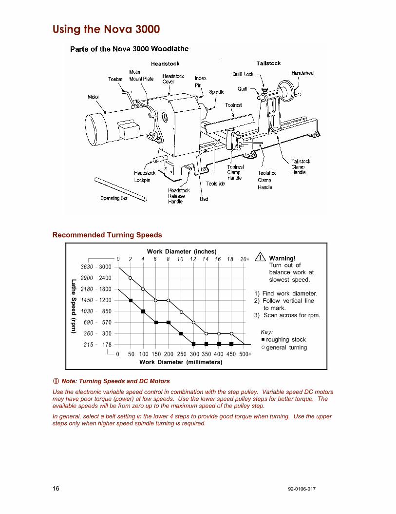
Using the Nova 3000
Recommended Turning Speeds
3630
2900
2180
1450
1030
690
360
215
3000
2400
1800
1200
850
570
300
1780 50 100 150 200 250 300 350 400 450 500+
0 2 4 6 8 10 12 14 16 18 20+Work Diameter (inches)
Work Diameter (millimeters)
1) Find work diameter.2) Follow vertical line to mark.3) Scan across for rpm.
Lathe Speed (rpm)
Warning!Turn out ofbalance work atslowest speed.
!
roughing stockgeneral turning
Key:
Note: Turning Speeds and DC Motors
Use the electronic variable speed control in combination with the step pulley. Variable speed DC motors may have poor torque (power) at low speeds. Use the lower speed pulley steps for better torque. The available speeds will be from zero up to the maximum speed of the pulley step.
In general, select a belt setting in the lower 4 steps to provide good torque when turning. Use the upper steps only when higher speed spindle turning is required.

92-0106-017 17
Changing Speeds Change speeds by moving the belt position on the two 8-step pulleys. The speeds vary due to the rpm's of the motor. Speed position can be checked by viewing the belt through the window at the front of the headstock.
Lathe Speed Selection
Country Motor rpm Lathe Speeds (rpm) United States, Canada 1725 215, 360, 904, 1030, 1450, 2180, 2900, 3630 Australia, New Zealand, UK, Europe, South Africa
1425
178, 300, 570, 850, 1200, 1800, 2400, 3000
! Warning! Don't apply excess tension to the belt. You should be able to push the belt down at the center point between the pulleys from 8-12 mm (5/16 – 1/2 inch) with your thumb. Excess belt tension can cause increased vibration, bearing wear, belt wear, and damage to the motor shaft.
1. Stop the lathe.
2. Loosen the screw knob and open the headstock guard.
3. Loosen the Teebar and pull the lever toward the front of the lathe to loosen the belt. Tighten the teebar to hold the motor while the belt position is changed.
4. Position the belt on the selected set of pulleys.
5. Push the Teebar away from the lathe to tension the belt and tighten the teebar.
6. Close the headstock guard and tighten the screw knob.
Teebar HeadstockGuard
ScrewKnob
Belt
more
lesstension
MotorPulley
BeltPositionWindow
! Tighten beltonly as muchas needed.
Swiveling the Headstock 1. Stop the lathe. Insert the operating
bar into a hole in the Headstock Lockpin. Loosen the Lockpin half a turn.
1. Slide the Headstock Release Handle towards Inboard end of lathe, and rotate the headstock to a detent position. Do not push down on the handle.
! Warning! Use the detent latch positions to prevent headstock movement during turning.
4. Firmly tighten the Headstock Lockpin with the operating bar; but do not use excessive force. Remove the operating bar.
HeadstockLockpin
HeadstockRelease Handle
Headstock
Operating Bar
90°
180°
45°22.5°
337.5°0°
Detent Positions
Right-Hand Turners Left-Hand Turners Detent Positions 0, 22.5, 45, 90 degrees 180, 337.5 degrees

18 92-0106-017
Spindle Index The spindle index pin locks the headstock spindle. It is selectable in 15 degree increments (24 divisions). There is sight hole to read index numbers (0 through 23).
1. Stop the lathe.
2. Pull the index knob and turn it left until the pin drops into the hole. To lock the spindle it must engage into a hole in the headstock pulley.
! Warning! Make sure the index pin is out before operating the lathe. The pin should drop into the indentation in the headstock to prevent it from engaging while the spindle is turning.
Pin
Sight HoleIndex Knob
HeadstockSpindle
Index pin shownin safe (operation)position
Divisions Index Number Degrees 2 0,12 180 3 0,8,16 (every 8th) 120 4 0,6,12,18 (every 6th) 90 6 0,4,8,12,16,20 (every 4th) 60 8 0,3,6,9,12,15,18,21 (every 3rd) 45 12 0,2,4,6,8…22 (every 2nd) 30 24 every hole 15
Headstock The headstock houses the motor pulley, headstock pulley, bearings, and the spindle. The headstock spindle accepts centers and accessories with no. 2 Morse taper (#2 MT), plus threaded faceplates and chucks.
Spindle Thread Size
Country Threads United States, Canada, UK 1-1/4 x 8 TPI RH Europe M33 x 3.5 RH
Australia, New Zealand, South Africa M30 x 3.5 RH
Mounting a faceplate or chuck 1. Use the spindle Index Pin to lock
the headstock spindle.
2. Screw the faceplate or chuck onto the spindle threads. A spindle washer in-between may be used to make removal easier.
! Warning! The faceplate or chuck body must contact the shoulder on the spindle bearing.
3. Pull and turn the Index Pin and place it in the "safe" indentation in the headstock.
Faceplate
Index Pin
HeadstockSpindle
Faceplate or chuck bodymust contact shoulder onthe spindle bearing.
!

92-0106-017 19
Using a spur center Mount the spur center to the work piece as shown and then insert the spur center and work piece into the headstock spindle.
! Warning! Do not pound work piece into headstock drive center when turning between centers or you may damage the headstock.
To remove the center, insert a 10 mm (3/8-inch) diameter wooden dowel or steel rod through the headstock spindle hole. While holding the center so it doesn’t fall, tap it out.
Mark stock centers For softwoods -punch centers
For hardwoods -drill centers and sawdiagonals for spur center Set spur center with mallet
Toolrest To move the toolslide along the bed, loosen the Toolslide Clamp Handle, move the slide to the desired position, and tighten the clamp handle.
To adjust the toolrest, loosen the Toolrest Clamp Handle, position the toolrest, and tighten the clamp handle.
Adjust the toolrest close to the work piece. Exact positioning may be varied to suit the turner. Before turning, revolve the stock by hand to make sure it clears the rest. At intervals, stop the lathe and readjust the toolrest.
! Warning! Lathe tools and chisels should remain on the toolrest whenever the tool is in contact with the work piece. Remove the toolrest when sanding or polishing so fingers do not get pinched.

20 92-0106-017
Tailstock
! Warning! Never loosen the tailstock quill or tailstock while the work piece is turning.
To move the tailstock along the bed, loosen the Tailstock Clamp Handle, slide the tailstock to the desired position, and tighten the clamp handle.
To move the tailstock quill in or out, loosen the Quill Lock and turn the Handwheel. Lock the quill in place with the Quill Lock.
The tailstock quill accepts centers and accessories with no. 2 Morse taper (#2 MT). To install a taper use a quick, firm action by hand. Do not pound the taper in.
To remove a taper, insert the operating bar through the tailstock quill hole. While holding the taper so it doesn’t fall, tap it out.
The tailstock quill is hollow, allowing you to bore holes through turnings if a hollow center is used.
Adjusting the Tailstock for Turning Between Centers 1. Mount the spur center to the work piece and insert the spur center into the headstock spindle, as
previously described under "Using a Spur Center".
! Warning! Do not use the tailstock quill action to drive the work piece into the spur center. This can create an unsafe and loose work piece.
2. Mount the live center into the tailstock quill using a quick, firm action by hand. 3. While holding the work piece, slide the tailstock to meet it and lock the tailstock in place. Turn the
Handwheel to apply light holding pressure to the work piece; it should turn easily by hand, yet not be loose. Tighten the Quill Lock.
Learning Turning The art and technique of turning is a subject beyond the scope of this instruction manual. It is recommended that you receive hands-on instruction on lathe turning and/or refer to books and videos on the subject. For reference, some woodturning books are:
Woodturning A Foundation Course by Keith Rowley
Turning Wood With Richard Raffan by Richard Raffan
Creative Woodturning by Dale Nish
The Fundamentals of Woodturning by Mike Darlow
92-0106-017 21
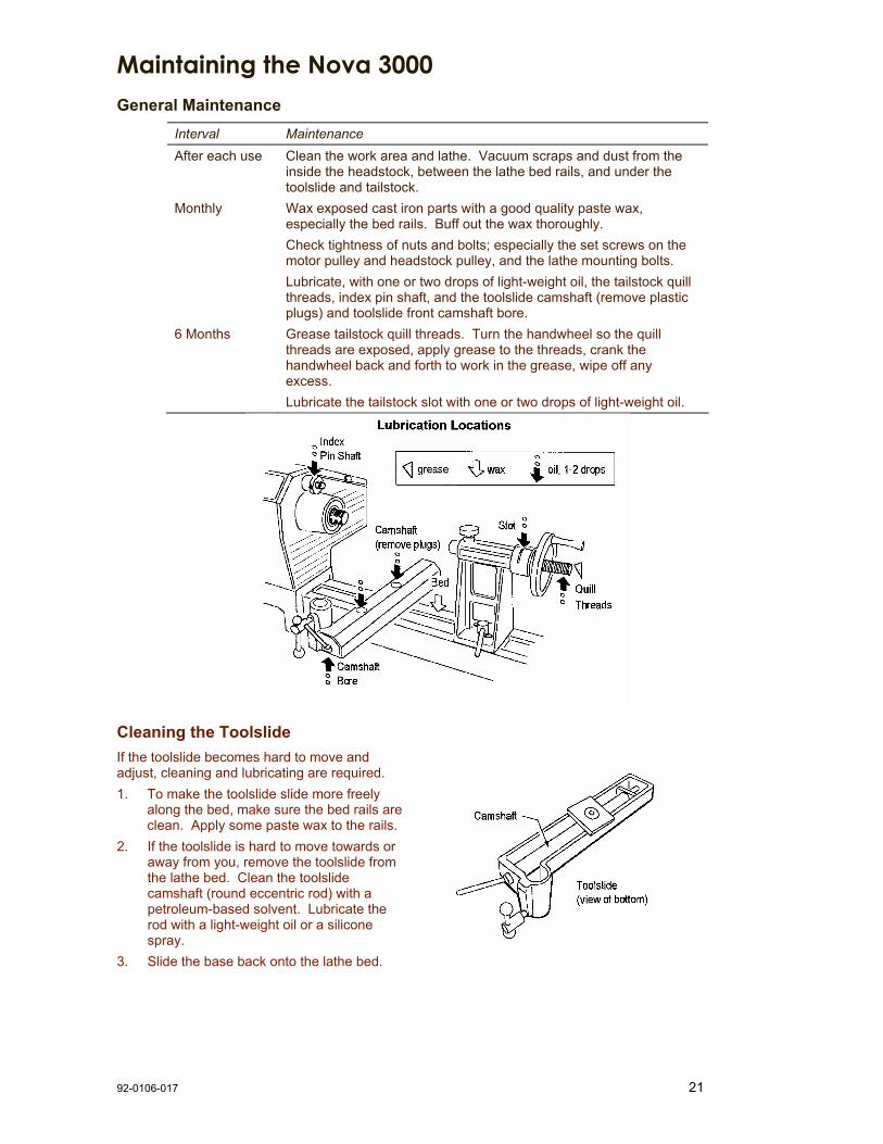
Maintaining the Nova 3000 General Maintenance
Interval Maintenance After each use Clean the work area and lathe. Vacuum scraps and dust from the
inside the headstock, between the lathe bed rails, and under the toolslide and tailstock.
Monthly Wax exposed cast iron parts with a good quality paste wax, especially the bed rails. Buff out the wax thoroughly. Check tightness of nuts and bolts; especially the set screws on the motor pulley and headstock pulley, and the lathe mounting bolts. Lubricate, with one or two drops of light-weight oil, the tailstock quill threads, index pin shaft, and the toolslide camshaft (remove plastic plugs) and toolslide front camshaft bore.
6 Months Grease tailstock quill threads. Turn the handwheel so the quill threads are exposed, apply grease to the threads, crank the handwheel back and forth to work in the grease, wipe off any excess. Lubricate the tailstock slot with one or two drops of light-weight oil.
Cleaning the Toolslide If the toolslide becomes hard to move and adjust, cleaning and lubricating are required. 1. To make the toolslide slide more freely
along the bed, make sure the bed rails are clean. Apply some paste wax to the rails.
2. If the toolslide is hard to move towards or away from you, remove the toolslide from the lathe bed. Clean the toolslide camshaft (round eccentric rod) with a petroleum-based solvent. Lubricate the rod with a light-weight oil or a silicone spray.
3. Slide the base back onto the lathe bed.

22 92-0106-017
Cleaning the Tailstock If the tailstock quill becomes hard to use or the Handwheel is hard to turn, cleaning and lubricating are required. 1. Remove the 6 mm set screw from the
tailstock. If necessary, turn the Handwheel to expose the set screw.
2. Using a screwdriver, remove the keeper plate from the tailstock body.
3. Remove the quill and Handwheel from the tailstock body.
4. Wipe clean all parts including the inside of the tailstock.
5. Lubricate the quill and tailstock slot with a light-weight oil and apply a small amount of grease to the quill threads.
6. Reassemble.
Aligning the Tailstock 1. Crank the Handwheel back so the quill is all the way in. 2. Place any #2 MT accessory you have that has a sharp point like a spur center, or live center in the tailstock quill and another center in the headstock spindle.
Note: Tailstock alignment can be made easier by using the Teknatool Acruline Accessory Center in place of the centers. 3. Move the tailstock close to the headstock so the two centers nearly touch; check the alignment of the center points. Move the tailstock away from the headstock and extend and lock the quill. The points of the centers should align when the quill is halfway extended, fully extended, and fully retracted. If the centers are aligned at all three locations no adjustment is necessary.
4. The tailstock does not meet the conditions in step 3, follow the steps below. This indicates that the tailstock is not parallel to the lathe bed and you will need to realign the tailstock. 5. First make sure the tailstock alignment plate is not binding inside the bed. If the tailstock doesn't move freely then remove the tailstock and look for burrs or high spots on the bed rails or the alignment plate. Using a smooth file remove any burrs or high spots. When done replace the tailstock on the bed. 6. Slightly loosen the two tailstock capscrews with a 5mm Allen wrench. Tap the tailstock with a wooden mallet in the appropriate direction to align the centers. Check and adjust the positioning of the tailstock. The centers should align when the quill is halfway extended, fully extended, and fully retracted, as previously described in step 3. 7. Lock the tailstock in place with the Tailstock Clamp Handle and fully tighten the two capscrews. The capscrews must be fully tightened in order to avoid slippage during work. 8. Check the alignment of the Tailstock by bringing it together with the Headstock with the Live center and Spur center in each spindle. The Points on the centers should be within 0.50mm (0.020") height and width of each other

92-0106-017 23
Troubleshooting Guide Problem Possible Cause and Solution
Excessive vibration. Out of balance, or large work piece. Reduce lathe speed to the lowest speed possible and turn the work piece to a true circle. Work piece is not held in the center. Check work piece mounting and correct. Work piece is not secure or held tight enough. Check work piece mounting and correct. Lathe incorrectly bolted to stand or bench. Refer to this manual for lathe stand recommendations. Stand or bench not well constructed, too light, or standing incorrectly on the floor. Make sure the stand is solidly constructed. Use sand bags to weigh down the stand. Over tensioning of belt is a primary cause of vibration. The drive belt is running badly, over tensioned, or damaged. Apply a spray-on belt dressing on the belt grooves, readjust belt tension, or replace the belt. Motor pulley is not in correct alignment with the headstock pulley. Loosen the motor pulley set screw and align the pulleys. Headstock is loose. Tighten the Headstock Lockpin. Headstock pulley or motor pulley is loose. Check that the pulley set screws are tight. The headstock guard is loose or rattling. Check that the guard screws are tight. Movement in motor mount plate. Check that the nyloc nuts on the headstock studs are tight, and that the Teebar is tight. Motor vibrates. Many single phase motors due to their design produce minor noise or vibrations; these usually cannot be altered.
Faceplate or chuck running out of true.
Dirt build up on the rear of the faceplates or chuck. Clean off all build up and dirt. Faceplates and chucks must mount securely against the inner bearing ring surface of the spindle.
Turning tools not sliding smoothly across Toolrest.
Damaged surface on toolrest face caused by sharp edged tools. File the toolrest using a fine smooth file and polish with extra fine sandpaper. Also remove the sharp edges from the corners of turning tools.
Spur drive center or live center not holding into the spindle taper or quill taper when turning.
Small end of Morse taper is damaged due to dropping or hitting. File or polish away any damage. Check that inside of tapers have not been scored. Grease or oil inside of Morse tapers. Wipe clean the inside of the tapers. Insufficient pressure when installing the center. Use a quick, firm action by hand to install a taper. Do not knock in using any solid object.
Note: Can't find the answer in this Troubleshooting guide?
Visit the Lathe Support Section on our website - this is packed with Frequently Asked Questions.
Or
Contact us (details are at the front of this manual)

24 92-0106-017
Troubleshooting Guide Problem Possible Cause and Solution
Difficulty in Adding Bed Extensions.
The alignment pins for the bed extension can be a very tight fit - to help ensure accurate bed/tailstock alignment. Try putting the pins in the freezer overnight, and heating up the bed segments with a hot air gun or dryer. This slightly shrinks the pins and expands the holes they go into.
Tailstock and headstock center not lining up correctly.
Tailstock not aligned to headstock; adjust as described under "Aligning the Tailstock". Bed incorrectly bolted to stand causing twist. Ensure stand and lathe are correctly installed. Headstock not returned to detent position after it has been rotated. Ensure that the headstock is locked into a detent position. Headstock Lockpin not fully seated. Twist the headstock back and forth to make sure it is properly seated and then tighten the Lockpin. Dirt or wood dust accumulated in the headstock swivel pin hole. Remove the Headstock Lockpin and clean out hole.
Clicking noise in headstock when lathe is operating.
Headstock pulley or motor pulley loose. Securely tighten the pulley set screws.
Tailstock handwheel hard to turn or will not turn.
Quill lock is locked; unlock the quill lock. If necessary, lightly tap a block of wood against the handwheel handle; tap the handle in a clockwise direction as viewed from the tailstock end. Build up of dust and wood resin on the quill or inside of the handwheel thread. Remove, clean, and lubricate the quill and tailstock as described under "Cleaning the Tailstock". The quill has been extended too far and is locked against the handwheel. Push the quill back into the tailstock when turning the handwheel.
Tailstock quill hard to move.
Quill lock is locked; unlock the quill lock. The quill is damaged; turn the handle to expose the quill and check for marks along the quill, especially on the edges of the slotted keyway. Remove the high spots with a smooth file and test the quill travel. Replace the quill if necessary.
Tailstock not locking correctly onto bed, or tailstock not sliding smoothly on bed ways.
Tailstock adjustment plate not adjusted correctly; adjust as described under "Aligning the Tailstock". Dirty bed ways and underside of tailstock body. Clean bed ways and underside of tailstock body with a petroleum-based solvent.
Tailstock binds. The inside of the bed has a high spot. File the area with a smooth flat file until the tailstock moves freely. The tailstock adjustment plate has a rough spot or a burr. Remove the tailstock and file the plate with a smooth flat file.
Tailstock jumps where bed sections join.
The machined flat surfaces are not flush. File the area with a smooth flat file until the tailstock moves freely.

92-0106-017 25
Nova 3000 Woodlathe Parts List See the parts list on page 26.

26 92-9907-016
Nova 3000 Woodlathe Parts List Most items are applicable to all countries; items listed with a "Y" are applicable to United States and Canada; items listed with "Q" are applicable to New Zealand, Australia, UK, Europe, and South Africa.
Item Qty Part No. Description
1 1 24000 Main Lathe Bed 2 3 NN12 Nut Hex Nyloc M12 ZP 3 1 24023 Detent Pin D12 G/F #19 4 2 24060 Compression Spring 5 1 24088 Detent Pin Handle 6 1 24001 Bed Extension Unit 7 2 24041 Dowel Pin M12 x 36 8 2 24011 Capscrew M12 x 30 9 1 24002 Headstock 10 (Y) 1 24045 Spindle Headstock
1-1/4 x 8 TPI 10 (Q)
1 24024 Spindle Headstock M30 x 3.5
10 (4) 1 24103 Spindle Headstock M33 x 3.5
11 1 6306LLB (Rear) NTN 6306 Bearing 11Y 1 6207LLB (Front) SKF 6207-2RSI
Bearing 11Q 1 6306LLB (Front) NTN 6306 Bearing 12 1 EC30 Circlip External 30mm
(1.5 mm wide) 13 1 24080 Wire Form Circlip 14 1 24025 Pulley Headstock 15 1 24061 3/16 in. SQ Key in
M/S x 30 mm 16 1 2MTSPUR Spur Center #2MT 17 1 24062 Spindle Index Knob 18 1 TP131658 Bissel / Tension Pin
3/16 in. x 5/8 19 1 24063 Spindle Index Pin 20 1 DNNO8 M8 Brass Dome Nut 21 2 G0810 Set Screw M8 x 10
Knurled Point 22 2 865913 Ball Knob 3/4 in. DIA
with M6 thread 23 1 25001 TeeLock Arm M10 DIA x 85
with M6 threads 24 1 55048 Headstock Lockpin 25 1 24031 Swivel Pin Headstock 26 1 24039 Tailstock Adjustable Type 27 1 24064 Quill Tailstock 1 in. DIA
with M10 LH thread 28 1 24043 Handwheel, Tailstock 29 1 24087 Operating Bar 30 1 27001 Key Quill Lock 31 1 24019 Quill Lock Knob 32 1 24040 Keeper Plate -
Hardened Steel 33 2 G06010 Set Screw M6 x 10
Knurled Point 34 1 27000 Lock Stud Tailstock 35 2 55153 Lock Arms 36 1 24047 Plate, Adjustable Alignment
Item Qty Part No. Description
37 2 BHC08020 Capscrew Button Head M8 x 20
38 2 FW8 Washer Flat M8 x 16 ZP 39 7 FW12 Washer Flat M12 ZP
1.6 mm Thick 40 1 24008 Lockplate Tailstock
M12 ZP 1.6 mm Thick 42 1 2MTLC Live Center #2MT 44 1 24009 Toolslide Casting 45 1 24048 Cam Nut Toolslide 46 1 BNMZ12090 M12 x 90 Eng Bolt 47 1 K1225 M12 x 25 Allen Head
Flathead Screw 48 1 27002 Plate Toolslide Lock 49 1 24020 Camshaft Toolslide 50 1 24026 Teelock Body 51 2 HP-16 Plughole M16 Black 52 1 24066 Guard Headstock 53 1 24122 Flange, Motor Mount
combined Metric & NEMA 54 1 24050 Stud M12 x 60 Motor Mount 55 1 24051 Stud M12 x 75 Motor Mount 56 1 24046 Cam Casting for Motor Mount 57 1 24049 Teebar - Motor Mount 58 1 24015 Speed Indicator Label 62 Motor 63Y 1 MPWL19.05 Motor Pulley 8 step
3/4 in. Shaft 63Q 1 MPWL19 Motor Pulley 8 step
19mm Shaft 65 1 584J6 Belt Poly Vee 66 1 24055 M5 x 10 Knob (guard cover) 67 5 MP05010 Screw Pan Head Pozi
M5 x 10 ZP 69 1 TR300/1 Toolrest 300 mm with
1 in. DIA post 70Y 1 FP150Y Faceplate 150 mm
with 1-1/4 x 8 TPI 70Q 1 FP150Q Faceplate 150 mm
with M30 x 3.5 71Y 4 KC0608 3/8 x 1 UNC Allen Head
Flathead Screws 71Q 4 CM5010192 M6 x 20 Allen Head
Flathead Screws

Accessories Add On Bed Extension Extend the bed of your Nova 3000 Woodlathe for greater capacity for turning between centers. Each bed unit adds 510 mm (20 in.)
Lathe Stand The stand pieces are cast from a high grade of Cast iron with extremely good section thickness and CAD generated internal gussets at all critical points to withstand extremely high stresses with practically no distortion. Cast iron has always been the material of choice for wood lathe construction because of its inherent mass and excellent modulus of vibration dampening. The cast iron stand has been purposely designed to be heavy, solid and robust keeping this in mind. SuperNova Chuck A next-generation, self-centering chuck to securely hold round and square work pieces for centerless turning. The special Tuff Lock gearing delivers amazing holding power in both the contraction and expansion mode. It has an open-back for easy cleaning and can be tightened one-handed with an articulated key. It includes a screw chuck. A wide variety of optional jaws are available to hold almost any work piece.
SuperNovaChuck
Small Toolrest A small 100 mm (4 in.) toolrest (not shown) for turning small work pieces or reaching into recessed areas. Bowl Toolrest A curved toolrest which gives you better chisel support on both the outside and inside of a bowl. Because of the curve you are able to position your chisel support closer to the bowl.
Revolving Center System A multi-function live center system to expand your options when turning between centers. It includes quick change tapers: a hollow cup center point, threaded center, cone center, and an extension center. Made with three bearings and precision machined for a high quality finish.
RevolvingCenterSystem
Handwheel Unit The handwheel is mounted on the outboard end of the headstock spindle so you can manually position work or to slow it down. The vacuum coupler can also be added to this unit to make a vacuum holding option.
HandwheelUnit

28 92-0106-017
Accessories Faceplates Faceplates are used to mount the work piece when faceplate turning bowls or platters. Faceplates are available in 80 mm (3 in.) and 150 mm (6 in.) diameters. A vacuum faceplate is also available. The 80 mm (3 in.) faceplate is made of solid steel. This faceplate has a small contact area to allow maximum freedom while shaping. The 150 mm (6 in.) faceplate is made of light-weight aluminum and has a unique indexing feature. It can handle large work pieces up to 740 mm (29 in.) in diameter.
Vacuum Coupler The Vacuum Coupler (not shown) fits onto the Handwheel Unit. It provides a secure attachment for your vacuum cleaner hose. For those turners who are interested in vacuum chucking, this is a simple system.
Outrigger Unit Extend the bowl turning capacity of the Nova 3000 Woodlathe to up to 740 mm (29 in.) in diameter. This unit is made from cast iron, is easy to position and control, and mounts to the headstock end of the lathe.
For further details about Teknatool's lathe accessories please contact your local retailer for more information, or contact us for a free product catalogue. This catalogue can also be downloaded from our website - at www.teknatool.com.

92-0106-017 29
Index AC Motors, 8,10 Accessories, 27,28 Aligning the Tailstock, 22 Assembling, 11
Bed, Lathe, 14,27 Belt Tension, 17 Bowl version, 8
Camshaft, 21 Centerless Turning, 19 Centers, 11, 19, 20 Changing Speeds, 17 Chuck, 18, 27 Cleaning, 21,22 Components, 11, 16 Connecting to Power, 15 Contents, 4
DC Motors, 8,10,16 Distance between Centers, 8
Electrical, 15 Extension Bed, 14, 27 Extension Cords, 15
Faceplate, 11, 18, 28
Handles, 11, 13, 16 Handwheel, 27 Headstock Lockpin, 11, 16, 17 Headstock, 8, 16, 18
Lathe Stand Requirements, 9,15 Live Center, 20 Lubrication, 21
Maintenance, 21 Motor Mounting, 12 Motors, 8, 10 Mounting Faceplate or Chuck, 18 Mounting, Lathe, 8,15
Names of Components, 16 Nova 3000 Parts, 16 Nova 3000 Specifications, 8
Oil, 21 Operating, 17-21 Operating Bar, 16, 17, 19
Outrigger Unit, 28
Parts List, 25,26 Parts of the Nova 3000, 11, 16, 25, 26 Power, 15 Problems, 23
Quill, 8, 16, 22
Removing Centers and Tapers, 20 Revolving Center System, 27 Rpm, 17
Safety, 6,7 Sanding, 19 Shop Requirements, 9 Specifications, 8 Speed, 16,17 Spindle Index, 18 Spindle Threads, 8,18 Spur Center, 11,19 Stand, 9, 15, 27 Standard Equipment, 8 SuperNova Chuck, 18,27 Swing, 8 Swiveling the Headstock, 17
Tailstock parts list, 26 Tailstock, 8, 16, 20,22 Teebar, 12,13,16, 17 Teknatool, 4 Toolrest Options, 27 Toolrest Parts List, 26 Toolrest, 8, 16,19, 21 Troubleshooting, 23 Turning between Centers, 20 Turning Speeds, 16 Turning the Headstock, 17 Turning, 20
Unpacking, 11
Vacuum Coupler, 28 Vibration, 23
Warranty, 30 Website, 4 Work Diameters, 8,16 Workshop Requirements, 9
Teknatool Warranty

30 92-0106-017
Teknatool Five Year Limited Warranty This Teknatool product is backed by a FIVE YEAR warranty from the date of purchase. Teknatool International Ltd will repair or replace, at its expense and option, this Teknatool product which in normal use has proven to be defective in workmanship or material, provided that the customer returns the product prepaid to an authorized Teknatool service center with proof of purchase of the product within TWO YEARS and provides Teknatool with reasonable opportunity to verify the alleged defect by inspection. Furthermore, Teknatool International Ltd. extends this two year period for three additional years, excluding labor costs and drive belts, provided the aforementioned conditions are met. Motors and electronic controls are not covered under this warranty; these are warranted by their respective manufacturer.
Teknatool will not be responsible for any asserted defect which has resulted from normal wear, misuse, abuse, or repair or alteration made by anyone other than an authorized service facility or representative. Under no circumstances will Teknatool International Ltd. be liable for incidental, special, indirect, and consequential damages or expenses, including loss of profits or loss of operations. This warranty is Teknatool International Ltd. sole warranty. There are no other warranties, whether written or verbal, whether expressed or implied by law, trade, custom, or otherwise, whether of merchantability, fitness for purpose, or otherwise, except for remedies available to customers under the Consumer Guarantees Act or other legislation.
OVERSEAS CUSTOMERS: Our Teknatool Distributors and agents will issue their own warranty to cover this product. Terms may vary from those stated above; please check with your dealer. In North America warranty covers Continental USA only. For Alaska and Hawaii and other areas, warranty covers replacement of parts only and excludes transport costs.
Note: Did you know you can register your warranty with Teknatool online? Visit our website on www.teknatool.com to register your warranty faster today! Or you can fill out the card below, cut, fold, seal and post.
Teknatool Warranty Card
Return this card to validate your warranty, or register online at www.teknatool.com.
To help us provide services and products that are better tailored to your needs, please answer the following:
Name: ________________________________________
Address: ______________________________________
______________________________________________
______________________________________________
Email Address: _________________________________
Teknatool Product Model __________________________
Serial Number (under headstock cover)_________________
Date of Purchase ________________________________
Reseller _______________________________________
Would you like to be on our mailing list and receive complimentary copies of our Teknatool Newsletter? (Personal information is kept confidential.)
Yes, by normal mail Yes, by email No
1. Where did you purchase the product? (check one) Local Woodturning Specialty Manufacturer Local General Woodworking Mailorder Catalog
Other (specify) _____________________________________ 2. Did you receive all information you required and expected?
Yes No
If no, explain: ________________________________________ 3. What other products did you buy along with lathe purchase?
Lathe Chuck Finishes Power Tools Lathe Chisels Abrasives Other Products
Lathe Accessories (list) ______________________________ 4. Why did you buy the Nova Lathe?
Features Quality Warranty Store Advice Price NZ Made Accessories Product Support Recommended Reputation of Brand
5. Rate your woodturning and woodworking experience: Beginner Intermediate Advanced
Comments _____________________________________________
Note: To locate your unique lathe serial number, lift the guard on the headstock. The serial number is stamped
on the edge of the casting.

92-0106-017 31
Steps to registering your Warranty by Mail:
1. Fill out the information on page 30, duplicate your serial number here for your future reference:
Serial Number:________________________
2. Cut along the dotted line as indicated by the scissors icon.
3. Take the cut out, and fold along dotted line as shown.
4. Seal edges with sellotape/glue/tape etc.
5. Affix appropriate Postage Stamps for postage to New Zealand and post.
6. Optional: List your return address details in the event of mishandled post.
Affi
x Po
stag
e
Fold
H
ere
Fold
H
ere
Seal
Alo
ng E
dge
Seal
Alo
ng E
dge
Post
To:
TEK
NA
TOO
L IN
TER
NA
TIO
NA
L
War
rant
y R
egis
trat
ion
PO
Box
180
034
Luck
ens
Poi
nt
Hen
ders
on
Auc
klan
d 10
08
NE
W Z
EA
LAN
D
Ret
urn
Addr
ess:
____
____
____
____
____
____
__
____
____
____
____
____
____
__
____
____
____
____
____
____
__
____
____
____
____
____
____
__

32 92-0106-017
Nova 3000 Woodlathe Manual
Publication Code: 92-0106-017
© Teknatool International 2004