Embed Size (px)
Citation preview

Novel Options and Limitations of Methanol Based Production andStorage for Mobile ApplicationsD. Poetzsch,1& T. Bach,1§ J.E. Zerpa Unda,1¶ E. Roduner,1,2*
1 Institute of Physical Chemistry, University of Stuttgart, Pfaffenwaldring 55, D-70569 Stuttgart, Germany2 Chemistry Department, University of Pretoria, Pretoria 0002, Republic of South Africa
Received
[*] Corresponding author, [email protected][§] Present address: Fraunhofer Institute for Silicate Research, Neunerplatz 2, D-97082 Würzburg, Germany[&] Present address: Max-Planck-Institute for Solid State Research, Heisenbergstraße 1, D-70569 Stuttgart, Germany[¶] Present address: BASF SE, GCN/EP - M311, D-67056 Ludwigshafen, Germany
AbstractMethanol is considered a promising liquid fuel in context with electrochemical energy conversion and storage formobile applications. It is shown here that a direct methanol fuel cell can be used for spontaneous charging anddischarging a supercapacitor for intermediate storage of chemical energy. Thereby, protons and electrons of themethanol-derived hydrogen are stored separately in the electrical double layer of the supercapacitor electrode. Thecharging and discharging of this fuel cell-supercapacitor hybride device is investigated in experiments of spontaneousconditions (closed circuit) and also under externally enforced constant voltage sweep rate (cyclic voltammetry) andunder constant current conditions. Alternatively, gas phase hydrogen is generated from methanol in an electro-reforming process. When more efficient anode electrocatalysts become available this may become the method of choicefor on-board and on demand hydrogen production in mobile applications.
Keywords: Electrochemical Hydrogen Storage, DMFC-Supercapacitor Hybrid Device, Methanol Electro-Reforming,Charging of Porous Electrode
1 Introduction The prospects of the consequences of the increasing world energy demand, the continuing rise of the carbon dioxide
and other greenhouse gas content in the earth atmosphere and the impact of major accidents with fossil fuel handlingand nuclear energy production plants have led to tremendous support in the opinion that there is a need for alternativeenergy resources and new general energy technology. A significant problem arises because of the strongly cyclicdemand of energy on various timescales, depending on the application; at the same time many of the alternative energyresources depend on day-night or annual periodicity or on weather and are thus also cyclic, but uncorrelated withdemand. Therefore, energy storage on timescales of milliseconds to months is just as important an issue as energyconversion. Large scale storage is best done as chemical energy. The successful strategy under conditions of cyclic demand is often based on hybrid operation of more than onepower source. The base power can be covered by a sluggish source, while peak power is provided flexibly by a fastconverter or a storage medium which is recharged in times of low need. Fuel cells, for example, are best operated in arelatively narrow current-voltage range in order to minimize degradation processes which affect membrane andelectrodes. They can be complemented with batteries which in the past decade have made significant progress regardingenergy density. If a fast response is needed a supercapacitor may be a better solution, but with limited energy density.The complementary devices are often wired up in parallel. Here we show that a more integrated design is basically alsopossible.
Hydrogen is the chemical energy carrier with the highest gravimetric energy density, but since it is a gas, storageand transport are inconvenient for mobile applications. Various ways of hydrogen storage are being investigated, amongthem liquefaction at 20 K, compression in pressure tanks at up to 700 bar, physisorption on large surface area carbon ormolecular framework materials (MOFs), chemical storage in metal hydrides or in alanates, aminoborane, or theiramidoborane derivatives, or borohydrides [1,2]. Recently, H2 physisorption on lithium dodecahydro-dodeca-closo-borane, Li2B12H12 was suggested as a novel option for hydrogen storage [3]. It was shown that the entropy associatedwith volume compression to an adsorbed, condensed or simply compacted state requires energy corresponding to on theorder of 15% of the hydrogen lower heating value. This entropy term thus represents a fundamental barrier hinderingreversible storage. Recent work has explored a novel concept of hydrogen storage in which protons and electrons are electrochemicallyseparated on a polymer electrolyte membrane fuel cell-type electrode and then stored in the electrical double layer(EDL) of a supercapacitor-type electrode [4]. This is a spontaneous process at 1 bar H2 pressure and ambient
1
temperature. The hydrogen was recovered and directly converted to water at the same electrode, after the hydrogenatmosphere had been replaced by oxygen. This is also a spontaneous and energy producing process. In essence, thedevice is a hybrid of a hydrogen fuel cell with an integrated hydrogen buffer. The present work extends this concept tousing methanol as a fuel in place of hydrogen, and it has two separate fuel cell-type electrodes which permitsimultaneous or sequential operation of the anode and cathode, depending on demand. The EDL supercapacitor islocated between and wired up in series with anode and cathode. As a potential practical application one might envisagethe operation of a laptop which for much of its time has a low energy demand that is well covered by the sluggish anodereaction of methanol, allowing at the same time the buffer to be filled. At times of peak demand, for example duringwriting of a CD, the additional power is retrieved from the buffer. Instead of storing hydrogen, it may be prepared on-board from methanol or gasoline by a thermal steam reformingprocess. This requires a chemical reactor at a temperature of 250-360° and a pressure of ca. 20 bar, which poses specialstart-up procedures. Furthermore, the formation of CO has to be kept below ca. 50 ppm. These complications haveprompted some research organizations to disregard thermal reforming for automotive power trains [5]. Nevertheless,several Reformed Methanol Fuel cells (RMFC) designs have reached commercial status in niche applications. Here weevaluate further a recently reported alternative [6] that has not received much attention in literature so far. It consists inthe electrochemical conversion of aqueous methanol to H2 and CO2, which is the reaction that in principle occurs whenthe oxygen at the cathode of a direct methanol fuel cell is replaced by an inert gas so that the reaction stops at the stageof H2 without reacting further to water. With DG° = -15 kJ mol-1 the reaction is slightly exergonic and would occurspontaneously if it were not highly activated. A suitable catalyst can reduce the activation energy of a homogeneousreaction, but if conducted in a fuel cell type setup the reaction can be promoted further by application of an externalvoltage. It is therefore called electro-reforming. As for thermal steam reforming, methanol is carried along as a liquidfuel in mobile applications. The process of electro-reforming, however, should allow for much simpler constructiondesigns and operation.
2 Carbon Based Supercapacitor, Spontaneously Charged and Discharged by a DMFC2.1 The Concept With the exception of the metal hydrides, hydrogen is stored as a molecular entity, or as H atoms which are engagedin covalent chemical bonds. These reactions are far from being reversible. However, the standard hydrogen electrodetells us that gas phase hydrogen can be in equilibrium with solvated protons and compensating anions in water.Equilibration is fast and reversible at ambient temperature and pressure. We have therefore explored the possibility to separate protons and electrons on a fuel cell type anode and store thetwo particles separately on an electrical double layer (EDL) supercapacitor, i.e. the electrons on large surface areacarbon in contact with water where the solvated protons form the second half of the electrical double layer [4]. Thedischarge occurs at the cathode side of the fuel cell. The previous work used H2 as a fuel [4], but here we explore usinga direct methanol fuel cell (DMFC) with an EDL supercapacitor integrated in a split membrane.
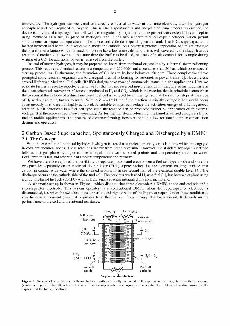
A schematic set-up is shown in Figure 1 which distinguishes three electrodes: a DMFC anode and cathode and asupercapacitor electrode. This system operates as a conventional DMFC when the supercapacitor electrode isdisconnected, i.e. when the switches of the upper left and right circuits of the Figure are open. Under these conditions aspecific constant current (IFC) that originates from the fuel cell flows through the lower circuit. It depends on theperformance of the cell and the internal resistance.
Figure 1: Scheme of hydrogen or methanol fuel cell with electrically contacted EDL supercapacitor integrated into the membrane(center of Figure). The left side of this hybrid device represents the charging at the anode, the right side the discharging of thecapacitor at the fuel cell cathode.
2
Specifically, protons and electrons are produced at the anode from the electrochemical oxidation of methanol duringthe charging process. The protons migrate from the anode through a Nafion® membrane towards the aqueous side ofthe supercapacitor electrode. At the same time the electrons flow through left half of the external circuit, producingelectrical work. In the charged state protons are stored in the aqueous electrolyte side and electrons in the carbonmaterial, thereby forming the double layer. During the discharging process the protons diffuse from the supercapacitorelectrode through a second Nafion® membrane towards the cathode, where they react with oxygen and electrons toproduce water and heat. Electrical work can be obtained during both processes.
It is important to highlight that the charging and discharging of this system is performed without the application ofany external electrical current or voltage. The system is much like a battery where an open circuit voltage (OCV) can bemeasured between the anode and the supercapacitor electrode just before charging and between the cathode and thelatter after charging (just before discharging). The origin of this OCV, which is the driving force for the charging-discharging process, is related to thermodynamic reasons and also to the presence of electroactive functionalities at thecarbon surface such as phenol, carbonyl, carboxyl, lactone, and the redox couple quinone/hydroquinone (Q/HQ) [7].These surface functionalities are associated to the pseudocapacitive behavior exhibited by carbon electrodes [8]. As aconsequence the total capacitive current measured during the charging-discharging process has two main contributions:a non-Faradaic, which involves the charging of the double layer, and a Faradaic associated to the potential dependentpseudocapacitive behavior of the carbon electrode.
Basically two charging-discharging processes are considered:· One related to the capacitance: MeOH + 7 H2O + {C} ¾ 6 H3O+ + {C}-6 + CO2 (Charging) (1) 6 H3O+ + {C}-6 + 3/2 O2 ¾ {C} + 9 H2O (Discharging) (2)· and a reaction related to the pseudocapacitance: MeOH + H2O + 6 >C=O ¾ 6 >C-OH + CO2 (Charging) (3) 6 >C-OH + 3/2 O2 ¾ 6 >C=O + 3 H2O (Discharging) (4)
Here, the redox reactions of pseudocapacitive functional groups are represented by >C=O and >C-O which in thiscase is associated to the Q/HQ pair. The symbol {C} refers to the carbon black electrode surface at which the doublelayer is formed.
2.2 Experimental Details2.2.1 Preparation of the Cell
For all measurements we used a homemade, acrylic cell. The cathode side was actively supplied by pure oxygen; theanode side passively by an aqueous methanol solution in a tank. Therefore, we call this DMFC semi-passive.
On both sides of the supercapacitor (SC) part a membrane electrode assembly (MEA) with the electrode on only oneside of the membrane was fixed. For the MEAs a gas diffusion layer (hydrophobic carbon paper from Freudenberg) waspainted with a catalyst ink in thin layers at 80 °C. The ink for the cathode contains carbon supported Pt (Alfa Aesar, 20wt.%), water and Nafion® ionomer suspension (Sigma-Aldrich, 10 wt.%). The anode ink used supported Pt/Ru (AlfaAesar, 40 wt.% Pt, 20 wt.% Ru) instead and additionally ethylene glycol for better adhesion [9]. The final metalloadings were 4.3 mg cm-2 and 1.8 mg cm-2 for the anode and cathode, respectively. These gas diffusion electrodes(GDE) were directly mounted together with Nafion® 117 membranes in the cell without hot pressing [10-13].
The SC consists of a graphite substrate (20×20 mm) with 100 holes (1 mm diameter) as current collector. This platewas coated with a paste of carbon black (Black Pearls 2000, CABOT Corporation) and water. The measured BETsurface area and micropore volume are 1155 m2 g−1 and 0.23 cm3 g−1, respectively [4]. The coatings differed from 2.7 to5.1 mg cm−2 carbon black. The holes were filled with sulfuric acid of various concentrations as electrolyte.
2.2.2 Electrochemical MeasurementsAll three parts of the cell were tightly mounted. Oxygen was supplied to the cathode at a flow rate of 22 mL min−1 at
ambient pressure and the anode tank was filled with 4 M aqueous methanol solution.Current-voltage characteristics were measured simply by connecting anode and cathode with a voltmeter in parallel
and an ampere meter in series with a variable resistance.All supercapacitor measurements were performed with a potentiostat/galvanostat 7050 from AMEL Instruments.
The SC was charged by three different methods: through a constant resistance, at constant current (galvanostatic) and atconstant voltage sweep rate (cyclic voltammetry). For charging the fuel cell anode, for discharging the fuel cell cathodewas electrically connected to the SC.
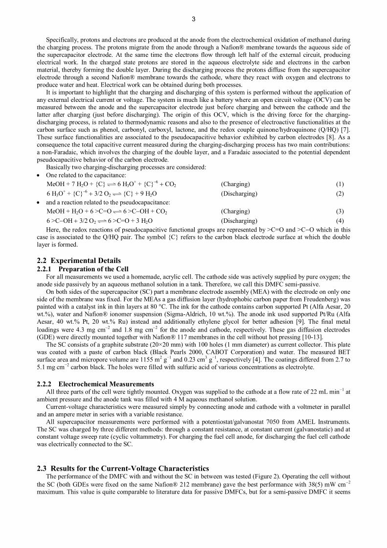
2.3 Results for the Current-Voltage CharacteristicsThe performance of the DMFC with and without the SC in between was tested (Figure 2). Operating the cell without
the SC (both GDEs were fixed on the same Nafion® 212 membrane) gave the best performance with 38(5) mW cm-2
maximum. This value is quite comparable to literature data for passive DMFCs, but for a semi-passive DMFC it seems
3
to be worse [10, 14-17]. A reason for this might be that the GDE was not hot-pressed with the membrane and thereforethe contact between them is not at its optimum. Another reason is that for each measurement under new conditions inthe SC the cell needed to be opened. This led to mechanical stress on the catalyst layer and decreased its performance.
Adding the SC between the two fuel cell electrodes decreased the performance of the DMFC rapidly as aconsequence of the higher internal resistance. 10 M sulfuric acid as electrolyte gave the best performance (4.3(1) mWcm-2) and was therefore used as electrolyte for all measurements.
Figure 2: Voltage polarization and power curves of the semi-passive DMFC with different electrolytes in the inserted supercapacitor.Circles: 85% H3PO4, squares: 1 M H2SO4, triangles up: 5 M H2SO4, triangles down: 10 M H2SO4, grey: DMFC in the absence ofinserted supercapacitor material; the corresponding power performance curve is not shown.
2.4 Resulting Supercapacitor Properties2.4.1 Charging through a constant resistance
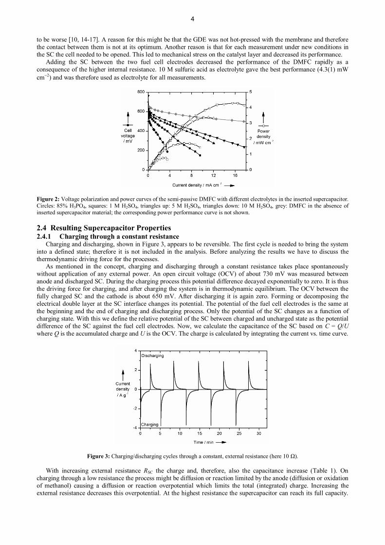
Charging and discharging, shown in Figure 3, appears to be reversible. The first cycle is needed to bring the systeminto a defined state; therefore it is not included in the analysis. Before analyzing the results we have to discuss thethermodynamic driving force for the processes.
As mentioned in the concept, charging and discharging through a constant resistance takes place spontaneouslywithout application of any external power. An open circuit voltage (OCV) of about 730 mV was measured betweenanode and discharged SC. During the charging process this potential difference decayed exponentially to zero. It is thusthe driving force for charging, and after charging the system is in thermodynamic equilibrium. The OCV between thefully charged SC and the cathode is about 650 mV. After discharging it is again zero. Forming or decomposing theelectrical double layer at the SC interface changes its potential. The potential of the fuel cell electrodes is the same atthe beginning and the end of charging and discharging process. Only the potential of the SC changes as a function ofcharging state. With this we define the relative potential of the SC between charged and uncharged state as the potentialdifference of the SC against the fuel cell electrodes. Now, we calculate the capacitance of the SC based on C = Q/Uwhere Q is the accumulated charge and U is the OCV. The charge is calculated by integrating the current vs. time curve.
Figure 3: Charging/discharging cycles through a constant, external resistance (here 10 Ω).
With increasing external resistance RSC the charge and, therefore, also the capacitance increase (Table 1). Oncharging through a low resistance the process might be diffusion or reaction limited by the anode (diffusion or oxidationof methanol) causing a diffusion or reaction overpotential which limits the total (integrated) charge. Increasing theexternal resistance decreases this overpotential. At the highest resistance the supercapacitor can reach its full capacity.
4
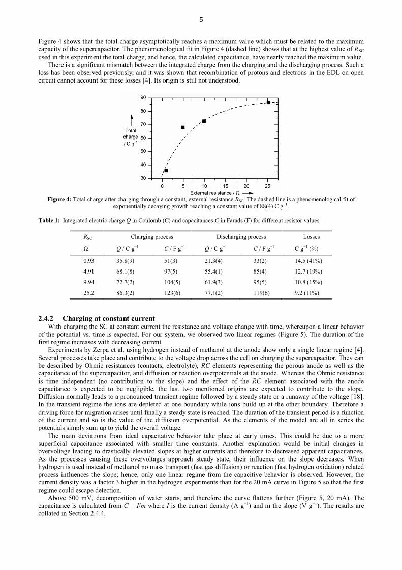
Figure 4 shows that the total charge asymptotically reaches a maximum value which must be related to the maximumcapacity of the supercapacitor. The phenomenological fit in Figure 4 (dashed line) shows that at the highest value of RSCused in this experiment the total charge, and hence, the calculated capacitance, have nearly reached the maximum value. There is a significant mismatch between the integrated charge from the charging and the discharging process. Such aloss has been observed previously, and it was shown that recombination of protons and electrons in the EDL on opencircuit cannot account for these losses [4]. Its origin is still not understood.
Figure 4: Total charge after charging through a constant, external resistance RSC. The dashed line is a phenomenological fit ofexponentially decaying growth reaching a constant value of 88(4) C g−1.
Table 1: Integrated electric charge Q in Coulomb (C) and capacitances C in Farads (F) for different resistor values
RSC Charging process Discharging process Losses
Ω Q / C g−1 C / F g−1 Q / C g−1 C / F g−1 C g−1 (%)
0.93 35.8(9) 51(3) 21.3(4) 33(2) 14.5 (41%)
4.91 68.1(8) 97(5) 55.4(1) 85(4) 12.7 (19%)
9.94 72.7(2) 104(5) 61.9(3) 95(5) 10.8 (15%)
25.2 86.3(2) 123(6) 77.1(2) 119(6) 9.2 (11%)
2.4.2 Charging at constant currentWith charging the SC at constant current the resistance and voltage change with time, whereupon a linear behavior
of the potential vs. time is expected. For our system, we observed two linear regimes (Figure 5). The duration of thefirst regime increases with decreasing current.
Experiments by Zerpa et al. using hydrogen instead of methanol at the anode show only a single linear regime [4].Several processes take place and contribute to the voltage drop across the cell on charging the supercapacitor. They canbe described by Ohmic resistances (contacts, electrolyte), RC elements representing the porous anode as well as thecapacitance of the supercapacitor, and diffusion or reaction overpotentials at the anode. Whereas the Ohmic resistanceis time independent (no contribution to the slope) and the effect of the RC element associated with the anodecapacitance is expected to be negligible, the last two mentioned origins are expected to contribute to the slope.Diffusion normally leads to a pronounced transient regime followed by a steady state or a runaway of the voltage [18].In the transient regime the ions are depleted at one boundary while ions build up at the other boundary. Therefore adriving force for migration arises until finally a steady state is reached. The duration of the transient period is a functionof the current and so is the value of the diffusion overpotential. As the elements of the model are all in series thepotentials simply sum up to yield the overall voltage.
The main deviations from ideal capacitative behavior take place at early times. This could be due to a moresuperficial capacitance associated with smaller time constants. Another explanation would be initial changes inovervoltage leading to drastically elevated slopes at higher currents and therefore to decreased apparent capacitances.As the processes causing these overvoltages approach steady state, their influence on the slope decreases. Whenhydrogen is used instead of methanol no mass transport (fast gas diffusion) or reaction (fast hydrogen oxidation) relatedprocess influences the slope; hence, only one linear regime from the capacitive behavior is observed. However, thecurrent density was a factor 3 higher in the hydrogen experiments than for the 20 mA curve in Figure 5 so that the firstregime could escape detection.
Above 500 mV, decomposition of water starts, and therefore the curve flattens further (Figure 5, 20 mA). Thecapacitance is calculated from C = I/m where I is the current density (A g−1) and m the slope (V g−1). The results arecollated in Section 2.4.4.
5

An alternative explanation of the two slopes will be derived based on the cyclic voltammetry experiments in Section2.4.3 and compared in Section 2.4.4.
Figure 5: Galvanostatic charging curves at various constant currents.
2.4.3 Charging at constant voltage sweep rateIn cyclic voltammetry (CV) the potential is controlled by a potentiostat. While the potential decreases exponentially
in the fully spontaneous process, it decays linearly in CV. An exemplary cyclovoltammogram at 50 mV s−1 sweep rateis shown in Figure 6. The first cycle differs considerably from the following ones. For this first cycle the SC is fullydischarged at the beginning. For the following cycles the SC stays partly charged and the system is in a more definedand stable state which leads to more reproducible cycles. The capacitance at different sweep rates is calculated fromC = IC/v, with IC being the capacitive current which equals the positive minimum of the CV, and v the sweep rate. Theresults are discussed in the next chapter.
Biesheuvel et. al. have investigated in detail the special effects occurring on capacitive charging of porous electrodes[19]. Measuring CV at different sweep rates provides different pieces of information. The formation of the double layerat the surface of a porous material can be separated into two processes which occur at different rates. The charging ofthe outer surface is quite fast as the ions do not have to migrate over a large distance. In contrast, charging the poresseems to take longer as the ions need to migrate inside, which might be inhibited by Coulomb repulsion. The sweep ratev provides access to this time regime. At very fast sweep rates mainly the surface is charged as the ions do not haveenough time to migrate into the pores. At very low sweep rates the ions can migrate into the pores and saturate the SC.Ardizzone et al. suggested convenient linear relations between the derived charge and the sweep rate for each of the twodiffusion processes (equations (5) and (6)) [20]. An inverse proportional dependence of the sweep rate to the diffusiontime is assumed. With a semi-infinite linear diffusion this leads to equation (5). As Q is proportional to v-1/2 Q-1 must beproportional to v1/2 (equation (6)). Nevertheless, a further discussion of the equations is not reasonable as they are morephenomenological. More details can be found in reference [20]. The constants k and k’ are of no experimental interest.With v extrapolating to infinite sweep rates near infinite k/v1/2 becomes zero and Qsurface can be calculated from theordinate intercept (equation (5), Figure 7, left). In the same way, Qtot is obtained from the ordinate intercept of equation(6) by extrapolating v to zero (Figure 7, right). The results are discussed in the following chapter.
surfacekQ Qv
= + (5)
'
tot
1 1 k vQ Q
= + (6)
6
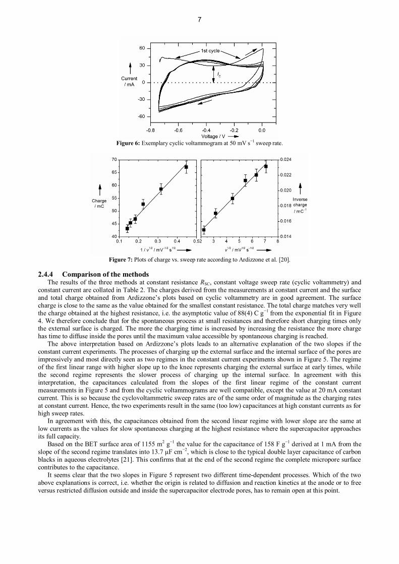
Figure 6: Exemplary cyclic voltammogram at 50 mV s−1 sweep rate.
Figure 7: Plots of charge vs. sweep rate according to Ardizzone et al. [20].
2.4.4 Comparison of the methodsThe results of the three methods at constant resistance RSC, constant voltage sweep rate (cyclic voltammetry) and
constant current are collated in Table 2. The charges derived from the measurements at constant current and the surfaceand total charge obtained from Ardizzone’s plots based on cyclic voltammetry are in good agreement. The surfacecharge is close to the same as the value obtained for the smallest constant resistance. The total charge matches very wellthe charge obtained at the highest resistance, i.e. the asymptotic value of 88(4) C g−1 from the exponential fit in Figure4. We therefore conclude that for the spontaneous process at small resistances and therefore short charging times onlythe external surface is charged. The more the charging time is increased by increasing the resistance the more chargehas time to diffuse inside the pores until the maximum value accessible by spontaneous charging is reached.
The above interpretation based on Ardizzone’s plots leads to an alternative explanation of the two slopes if theconstant current experiments. The processes of charging up the external surface and the internal surface of the pores areimpressively and most directly seen as two regimes in the constant current experiments shown in Figure 5. The regimeof the first linear range with higher slope up to the knee represents charging the external surface at early times, whilethe second regime represents the slower process of charging up the internal surface. In agreement with thisinterpretation, the capacitances calculated from the slopes of the first linear regime of the constant currentmeasurements in Figure 5 and from the cyclic voltammograms are well compatible, except the value at 20 mA constantcurrent. This is so because the cyclovoltammetric sweep rates are of the same order of magnitude as the charging ratesat constant current. Hence, the two experiments result in the same (too low) capacitances at high constant currents as forhigh sweep rates.
In agreement with this, the capacitances obtained from the second linear regime with lower slope are the same atlow currents as the values for slow spontaneous charging at the highest resistance where the supercapacitor approachesits full capacity.
Based on the BET surface area of 1155 m2 g−1 the value for the capacitance of 158 F g−1 derived at 1 mA from theslope of the second regime translates into 13.7 µF cm−2, which is close to the typical double layer capacitance of carbonblacks in aqueous electrolytes [21]. This confirms that at the end of the second regime the complete micropore surfacecontributes to the capacitance.
It seems clear that the two slopes in Figure 5 represent two different time-dependent processes. Which of the twoabove explanations is correct, i.e. whether the origin is related to diffusion and reaction kinetics at the anode or to freeversus restricted diffusion outside and inside the supercapacitor electrode pores, has to remain open at this point.
7
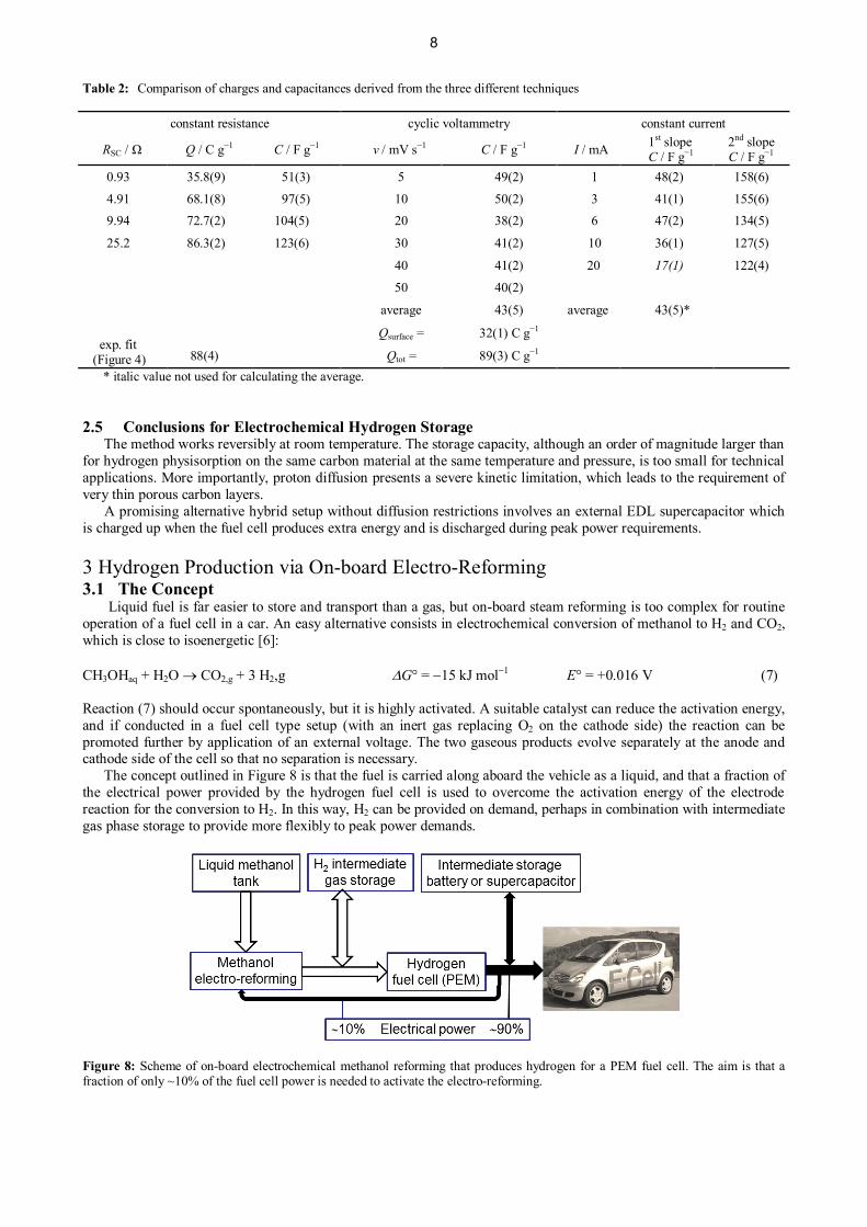
Table 2: Comparison of charges and capacitances derived from the three different techniques
constant resistance cyclic voltammetry constant current
RSC / Ω Q / C g−1 C / F g−1 v / mV s−1 C / F g−1 I / mA 1st slopeC / F g−1
2nd slopeC / F g−1
0.93 35.8(9) 51(3) 5 49(2) 1 48(2) 158(6)
4.91 68.1(8) 97(5) 10 50(2) 3 41(1) 155(6)9.94 72.7(2) 104(5) 20 38(2) 6 47(2) 134(5)
25.2 86.3(2) 123(6) 30 41(2) 10 36(1) 127(5)
40 41(2) 20 17(1) 122(4)
50 40(2)
average 43(5) average 43(5)*
exp. fit (Figure 4)
Qsurface = 32(1) C g−1
88(4) Qtot = 89(3) C g−1
* italic value not used for calculating the average.
2.5 Conclusions for Electrochemical Hydrogen Storage The method works reversibly at room temperature. The storage capacity, although an order of magnitude larger thanfor hydrogen physisorption on the same carbon material at the same temperature and pressure, is too small for technicalapplications. More importantly, proton diffusion presents a severe kinetic limitation, which leads to the requirement ofvery thin porous carbon layers. A promising alternative hybrid setup without diffusion restrictions involves an external EDL supercapacitor whichis charged up when the fuel cell produces extra energy and is discharged during peak power requirements.
3 Hydrogen Production via On-board Electro-Reforming3.1 The Concept
Liquid fuel is far easier to store and transport than a gas, but on-board steam reforming is too complex for routineoperation of a fuel cell in a car. An easy alternative consists in electrochemical conversion of methanol to H2 and CO2,which is close to isoenergetic [6]:
CH3OHaq + H2O ® CO2,g + 3 H2,g DG° = -15 kJ mol-1 E° = +0.016 V (7)
Reaction (7) should occur spontaneously, but it is highly activated. A suitable catalyst can reduce the activation energy,and if conducted in a fuel cell type setup (with an inert gas replacing O2 on the cathode side) the reaction can bepromoted further by application of an external voltage. The two gaseous products evolve separately at the anode andcathode side of the cell so that no separation is necessary. The concept outlined in Figure 8 is that the fuel is carried along aboard the vehicle as a liquid, and that a fraction ofthe electrical power provided by the hydrogen fuel cell is used to overcome the activation energy of the electrodereaction for the conversion to H2. In this way, H2 can be provided on demand, perhaps in combination with intermediategas phase storage to provide more flexibly to peak power demands.
Figure 8: Scheme of on-board electrochemical methanol reforming that produces hydrogen for a PEM fuel cell. The aim is that afraction of only ~10% of the fuel cell power is needed to activate the electro-reforming.
8
3.2 Experimental detailsA commercial demonstrator DMFC from h-tec, unfortunately with undisclosed membrane and electrode
composition, was used to investigate the electrochemical reforming. According to the manufacturer power densities ofup to 3 mW cm-2 can be reached when the demonstrator is run in the intended DMFC mode. All experiments wereperformed in galvanostatic mode using an Amel 7050 bipotentiostat, and the voltages were measured using a Fluke 189True RMS Multimeter. Both devices were interfaced to a PC using Win XP. A Plexiglas® cap was machined and mounted on the cathode side to collect the evolving gas and measure it bymeans of an inverted burette that was initially filled with water and connected to a compensating pressure reservoir. Thecathode compartment was prefilled with hydrogen gas at ambient pressure. 0.5 M, 1.0 M and 2.0 M aqueous methanol solutions were prepared using LiChrosolv methanol in bidistilled water.Faradaic efficiencies were calculated by relating the amount of evolved hydrogen to the time-integrated current. Thisfuel was recirculated through the cell by means of an electrical pump and regularly replaced to avoid any depletion ofconcentration.
3.3 Results and Discussion The maximum efficiency of a direct methanol fuel cell operated with 2 M aqueous methanol is temperaturedependent and amounts to 19% at a temperature of 313 K and a current density of 150 mA cm-2 [22]. This efficiency isto be compared with that of a PEM fuel cell operated with hydrogen from an autothermal methanol reformer. Geissler etal. found that only 4% of the methanol’s energy content is lost during the reforming and gas clean-up process(preferential CO oxidation) [23]. Only about 50% of the hydrogen energy is converted to electrical energy, and about20% of the generated electric power is used for driving auxiliary equipment (compressors, pumps). This reduces the netelectrical energy that is available for the vehicle to 33% of the energy content in the methanol feed. Both the DMFC andin particular the autothermal reformer combined with hydrogen PEM thus compare favorably with the 17% fuel cycleefficiency of current state-of-art internal combustion engines [24].
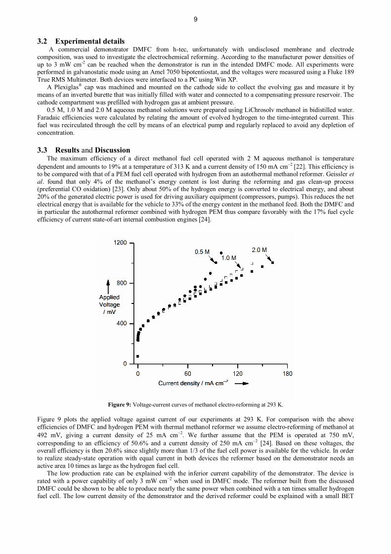
Figure 9: Voltage-current curves of methanol electro-reforming at 293 K.
Figure 9 plots the applied voltage against current of our experiments at 293 K. For comparison with the aboveefficiencies of DMFC and hydrogen PEM with thermal methanol reformer we assume electro-reforming of methanol at492 mV, giving a current density of 25 mA cm-2. We further assume that the PEM is operated at 750 mV,corresponding to an efficiency of 50.6% and a current density of 250 mA cm-2 [24]. Based on these voltages, theoverall efficiency is then 20.6% since slightly more than 1/3 of the fuel cell power is available for the vehicle. In orderto realize steady-state operation with equal current in both devices the reformer based on the demonstrator needs anactive area 10 times as large as the hydrogen fuel cell. The low production rate can be explained with the inferior current capability of the demonstrator. The device israted with a power capability of only 3 mW cm−2 when used in DMFC mode. The reformer built from the discussedDMFC could be shown to be able to produce nearly the same power when combined with a ten times smaller hydrogenfuel cell. The low current density of the demonstrator and the derived reformer could be explained with a small BET
9

surface and low catalyst loadings on the anode. Anyway, the discussed setup with the improvised electrochemicalreformer was almost able to reach the power densities promised for DMFC mode. Good efficiencies were also obtainedfor a constant load. If the applied voltage could be reduced even more this would change the picture dramatically,considering that electro-reforming is far less complex than steam reforming. Recently, promising novel, efficienthomogeneous ruthenium complex catalysts have been developed for aqueous phase methanol dehydrogenation tohydrogen and carbon dioxide [25, 26]. It remains to be seen whether they can also be used as electrocatalysts in theabove electro-reforming process, marking the next step towards a methanol economy.
4 Conclusions We have analyzed two options for the use of methanol in electrochemical energy conversion and storage. In amodified DMFC with integrated large surface area supercapacitor protons and electrons can be stored reversibly in anelectrical double layer. This can be viewed as an alternative way of hydrogen storage which provides a buffer to adaptflexibly to cyclic energy demand. Because it involves diffusion of protons the method is limited to thin layers ofsupercapacitor materials. A set-up in which a conventional supercapacitor is wired up in parallel rather than in serieswith the DMFC electrodes is preferred since it would respond faster and avoid extra resistance in the DMFC. Secondly, we have analyzed electro-reforming of methanol for providing hydrogen flexibly. The concept isattractive because of its simplicity compared with thermal steam reforming. However, with conventional anodeelectrocatalysts the activation of the reaction is still high and leads to severe losses for the process which according tothermodynamic criteria is spontaneous. Nevertheless, it was shown that the current densities reached are comparable tothose of an equivalent DMFC with the same catalyst loading and membrane electrode assembly. This can easily beunderstood as it is know that hydrogen reduction and oxidation are very facile in comparison to methanol oxidation [27-29]. Therefore the additional step comes with virtually no efficiency penalty. Furthermore, in a typical applicationscenario, the reformer makes decoupling of the sluggish methanol from load peaks possible. As hydrogen fuel cellsprovide superior efficiencies at high power densities and the reformer could stay in its sweet spot, the overall setupwould attain higher efficiencies than a comparable DMFC and necessitate less catalyst and therefore less preciousmetal.
References1 U. Eberle, M. Felderhoff, F. Schüth, Angew. Chem. Int. Ed., 2009, 48, 6608.2 W. I. F. David, Faraday Discuss. 2011, 151, 399.3 L. Dienberg, R. Haug, G. Rauhut, E. Roduner, Phys. Chem. Chem. Phys. 2013, 15, 5836.4 J. E. Zerpa Unda, E., Roduner, 2012, Phys. Chem. Chem. Phys., vol. 14, pp. 3816-3824.5 Department of Energy - United States of America, On-board fuel processing go/no-go decision: DOE Decision
Team Committee Report, 2004. http://www1.eere.energy.gov/hydrogenandfuelcells/pdfs/committee_report.pdf.6 C. R. Cloutier, D.P. Wilkinson, Int. J. Hydrogen Energy, 2010, 35, 3967.7 K. Kinoshita, in Carbon: Electrochemical and physicochemical properties, John Wiley & Sons, New York, 1988,
93.8 V. V. Panic, R. M. Stevanovic, V. M. Jovanovic, A. B. Dekanski, J. Power Sources 2008, 181, 186.9 K.-A. Starz, R. Zuber, A. Krämer, K. Fehl, J. Köhler, S. Wittpahl, in European Patent Specification, Vol. EP 1176
652 B1, Germany, 2002.10 J. G. Liu, T. S. Zhao, R. Chen, C. W. Wong, Electrochem. Commun., 2005, 7, 288.11 J. G. Liu, T. S. Zhao, Z. X. Liang, R. Chen, J. Power Sources, 2006, 153, 61.12 K.-W. Park, H.-J. Ahn, Y.-E. Sung, J. Power Sources, 2002, 109, 500.13 T. Yuan, Z. Q. Zou, M. Chen, Z. L. Li, B. J. Xia, H. Yang, J. Power Sources, 2009, 192, 423.14 D. J. Kim, E. A. Cho, S. A. Hong, I. H. Oh, H. Y. Ha, J. Power Sources, 2004, 130, 172.15 Q. Z. Lai, G. P. Yin, Z. B. Wang, Int. J. Energy Research, 2009, 33, 719.16 J. G. Liu, G. Q. Sun, F. L. Zhao, G. X. Wang, G. Zhao, L. K. Chen, B. L. Yi, Q. Xin, J. Power Sources,
2004, 133, 175.17 17 X. G. Wang, J. H. Liao, C. P. Liu, W. Xing, T. H. Lu, Electrochem. Commun., 2009, 11, 1918 P. Delahay, G. Mamantov, Anal. Chem. 1955, 27, 478.19 R. Zhao, M. van Soestbergen, H.H.M. Rijnaarts, A. van der Wal, M.Z. Bazant, P.M. Biesheuvel, J. Colloid Interface Sci., 2012, 384, 38.20 S. Ardizzone, G. Fregonara, S. Trasatti, Electrochim. Acta, 1990, 35, 263.21 M. Boero, T. Ikeshoji and K. Terakura, ChemPhysChem, 2005, 6, 1775.22 S. H. Seo, C. S. Lee, Appl. Energ., 2010, 87, 2579.23 K. Geissler, E. Newson, F. Vogel, T.-B. Truong, P. Hottinger, A. Wokaun, Phys. Chem. Chem. Phys., 2001, 3, 289.24 L. Gubler, H. Kuhn, T. J. Schmidt, G. G. Scherer, H.-P. Brack, K. Simbeck, Fuel Cells, 2004, 4, 196.25 M. Nielsen, E. Alberico, W. Baumann, H.-J. Drexler, H. Junge, S. Gladiali, M. Beller, Nature, 2013, 495, 85.26 R. E. Rodriguez-Lugo, M. Trinicado, M. Vogt, F. Tewes, G. Santiso-Quinones, H. Grützmacher, Nature Chemistry,
2013, 5, 342.
10

27 C. R. Cloutier, D. P. Wilkinson, Int. J. Hydrogen Energ. 2010, 35, 3967.28 F. Barbir, PEM fuel cells: Theory and practice, Elsevier Academic Press, Amsterdam; Heidelberg [u.a.] 2005.29 J. Wu, X. Z. Yuan, H. Wang, M. Blanco, J. J. Martin, J. Zhang., Int. J. Hydrogen Energ. 2008, 33, 1735.
11