Embed Size (px)
Citation preview

General rights Copyright and moral rights for the publications made accessible in the public portal are retained by the authors and/or other copyright owners and it is a condition of accessing publications that users recognise and abide by the legal requirements associated with these rights.
Users may download and print one copy of any publication from the public portal for the purpose of private study or research.
You may not further distribute the material or use it for any profit-making activity or commercial gain
You may freely distribute the URL identifying the publication in the public portal If you believe that this document breaches copyright please contact us providing details, and we will remove access to the work immediately and investigate your claim.
Downloaded from orbit.dtu.dk on: Apr 09, 2019
Novel Predictive Stator Flux Control Techniques for PMSM drives
Huang, Shoudao ; Wu, Gongping; Rong, Fei; Zhang, Changfan ; Huang, Sheng; Wu, Qiuwei
Published in:I E E E Transactions on Power Electronics
Publication date:2018
Document VersionEarly version, also known as pre-print
Link back to DTU Orbit
Citation (APA):Huang, S., Wu, G., Rong, F., Zhang, C., Huang, S., & Wu, Q. (Accepted/In press). Novel Predictive Stator FluxControl Techniques for PMSM drives. I E E E Transactions on Power Electronics.

Novel Predictive Stator Flux Control Techniques for PMSM drives Shoudao Huang, Senior Member IEEE, Gongping Wu, Fei Rong, Member IEEE,
Changfan Zhang, Sheng Huang, Qiuwei Wu, Senior Member IEEE
Abstract—In this paper, a predictive stator flux control (PSFC)algorithm for permanent magnet
synchronous motor (PMSM) drives is proposed, which can eliminate the influence of flux linkage
parameter perturbation and rotor position error. First, the sensitivity of conventional predictive current
control (PCC) to the flux linkage parameter and rotor position is analyzed. Then, the novel composite
discrete time sliding mode observer (SMO) based on stator flux state is designed, which can estimate the
flux linkage parameter perturbation, rotor position error and load torque simultaneously. Finally, a novel
PSFC method is developed, which can enhance the robustness of PCC against flux linkage parameter
perturbation and rotor position error by using composite discrete time SMO. Simulation and
experimental results indicate that the proposed PSFC can achieve low stator current harmonics, low
torque ripple and excellent steady-state performance under the flux linkage parameter perturbation and
rotor position error.
Index Terms—Sliding mode observer, flux linkage parameter perturbation, rotor position error,
permanent magnet synchronous motor, predictive current control.
I. INTRODUCTION
PERMANENT magnet synchronous motor (PMSM) drives have been extensively employed in industrial
applications, such as robots, electrical vehicles, and wind power generators[1,2], due to its advantages of
compact structure, excellent dynamic properties, high performance operations [3,4]. In order to achieve desired
servo control performance, field-oriented control (FOC) strategy has been used in most PMSM drive systems.
In an FOC-based PMSM drive, the double loop controller is usually adopted. The outer loop controller is to
control rotor speed, and the inner loop controller is to control stator current. The PCC has received extensive

attention for the inner loop controller as it has the advantages of excellent transient response characteristics and
accurate reference current tracking [5,6].
The performance of PCC method crucially depends on the accuracy of the stator inductance, flux linkage
parameter as well as rotor position. However, the permanent magnet (PM) flux linkage parameter may change
due to temperature rise and magnet saturation, especially under high temperature operation conditions[7]. In
engineering, a 20% flux reduction for a ferrite-based magnet occurs per 100 °C increase in ambient temperature
[8]. Although the permanent magnet has positive coefficient of coercivity, the flux linkage parameter of the
motor still changes with the temperature variation, especially the motor used in tank and high-speed train. On
the other hand, the rotor position measured by the resolver or the encoder attached to the PMSM shaft may
deviate from the true position due to the misalignment of the mechanical sensor components mounted on the
PMSM [9-11], which causes the Park coordinate transformation providing a mistaken feedback current to the
PCC algorithm. As a result, the control performance of the PMSM is deteriorated.
The main approach to improve flux linkage parameter robustness for the PCC is based on identification. In
[12], an improved deadbeat PCC algorithm based on stator current and disturbance observer is proposed for the
PMSM drive systems, which can optimize the PCC performance of the PMSM system with flux linkage
parameter mismatch. In[13], a Kalman filter and a Luenberger observer are designed to estimate rotor state
variables. In [14,15], the robust PCC algorithm based on disturbance observer is adopted for the PMSM drives,
which can overcome flux linkage parameter mismatch on the effect of the PCC and obtain high dynamic
performance. In [16], a robust fault-tolerant PCC algorithm based on a composite SMO is proposed for PMSM,
which can guarantee the performance of the system regardless of parameter perturbation, permanent magnet
demagnetization, and one step delay. In [17], a model-free PCC method of interior PMSM drives based on a
current difference detection technique is proposed, which does not require any motor parameters. However, the

higher current sampling frequency tends to limit its industrial application. In [18,19], a flux immunity robust
PCC algorithm for PMSM drives is proposed to eliminate the using of PM flux linkage parameter in prediction
model, but the method ignores the effect caused by rotor position measurement error.
The accuracy of rotor position is crucial for FOC when the minimum torque ripple is demanded over the
entire operating range of the motor. In [9-11], the experimental results show that the torque oscillation caused
by other factors is almost negligible compared with the rotor position error. In [20], a PMSM torque predictive
control scheme is proposed, which can eliminate high current harmonics and torque ripples caused by rotor
position error. In [21], a new torque predictive control method of PMSM drives is proposed, which can control
the torque by using the magnitude of the stator voltage vector. In [22], the sensorless predictive torque control
scheme relies on the anisotropy of the inductance is proposed, which can achieve the low torque ripple during
the full speed range. The control methods mentioned above provide low torque ripple under rotor position error.
However, the flux linkage parameter is looked on as constant in these control methods, which can’t be
guaranteed in engineering.
In this paper, a novel PSFC techniques is developed to guarantee the performance of PMSM drives regardless
of flux linkage parameter perturbation, rotor position error, and one step delay in digital control. In contrast to
the conventional PCC method, the proposed PSFC method can achieve the lower torque ripple and stator current
harmonics by applying a novel composite discrete time SMO based on stator flux state. The performance of the
proposed PSFC method is validated by simulation and experimental results.
This paper is organized as follows. A nonlinear PMSM model under flux linkage parameter perturbation and
rotor position error is developed in section II. The influence of flux linkage parameter perturbation and rotor
position error on conventional PCC is analyzed in Section III. The PSFC method is proposed in Section IV. The
composite discrete time SMO based on stator flux state is designed in Section V. The simulations and

experiments are setup in Section VI and Section VII, respectively. Section VIII concludes this paper.
II. NONLINEAR PMSM MODEL
The voltage state-space equations of the PMSM are described in Eq. (1) [18].
1
1
qdd q d
d d d
q d roq d q
q q q q
Ldi Ri i u
dt L L L
di LRi i u
dt L L L L
(1)
where, qq
d
Li
L and d
dq
Li
L are d-and q-axis cross-coupling terms, respectively. According to (1), the voltage
state-space equations of the SPMSM are,
1
1
dd q d
q roq d q
di Ri i u
dt L Ldi R
i i udt L L L
(2)
For surface-mounted PMSM (SPMSM), d qL L L . The d-and q-axis cross-coupling terms are qi and
di , respectively. According to (2), the d-and q-axis voltage equations of the SPMSM are,
dd d q
qq q d
du Ri
dtd
u Ridt
(3)
where,
= +
=d d ro
q q
Li
Li
The electromagnetic torque produced by the SPMSM is,
3 3
2 2
q
e p ro q p roT n i nL
(4)
The mechanical dynamic model of the SPMSM can be described as follows,
e L
p
J dT T
n dt
(5)
where, du and qu represent the d-and q-axis stator voltages, respectively; di and qi are the d-and q-axis currents,

respectively; d and q are the d-and q-axis stator flux components, respectively; R, L and J are the stator
resistance, stator inductance and the moment of inertia, respectively; is the electrical rotor speed, ro is the
flux linkage, pn is the number of pole pairs, eT is the electromagnetic torque, and LT is the load torque.
o
d
A
B
q
ro
C
rrdrq
N
S
Fig. 1. Variation of PMSM flux linkage.
The variation of flux linkage is illustrated in Fig. 1. Where, “ o ” and “ ” are the actual value and
measurement value of the rotor position, respectively. There exists an error between and o when the rotor
position measurement is inaccurate.“ r ” and“ ro ”are the actual and nominal values of the flux linkage
parameters, respectively. There also exists an error between “ r ” and “ ro ” due to temperature rise and
saturation. The flux linkage parameter perturbation rate is defined as,
ro r
ro
(6)
The d-and q-axis flux linkage equations can be expressed as follows when there exists flux linkage parameter
perturbation and rotor position error.
d ro d rd
q q rq
Li
Li
(7)
with,
cos( ) (1 )cos( ) 1
sin( ) (1 )sin( )rd r ro ro
rq r ro
(8)
where, rd and rq are the d-and q-axis flux linkage components under flux linkage parameter perturbation
and rotor position error, respectively.
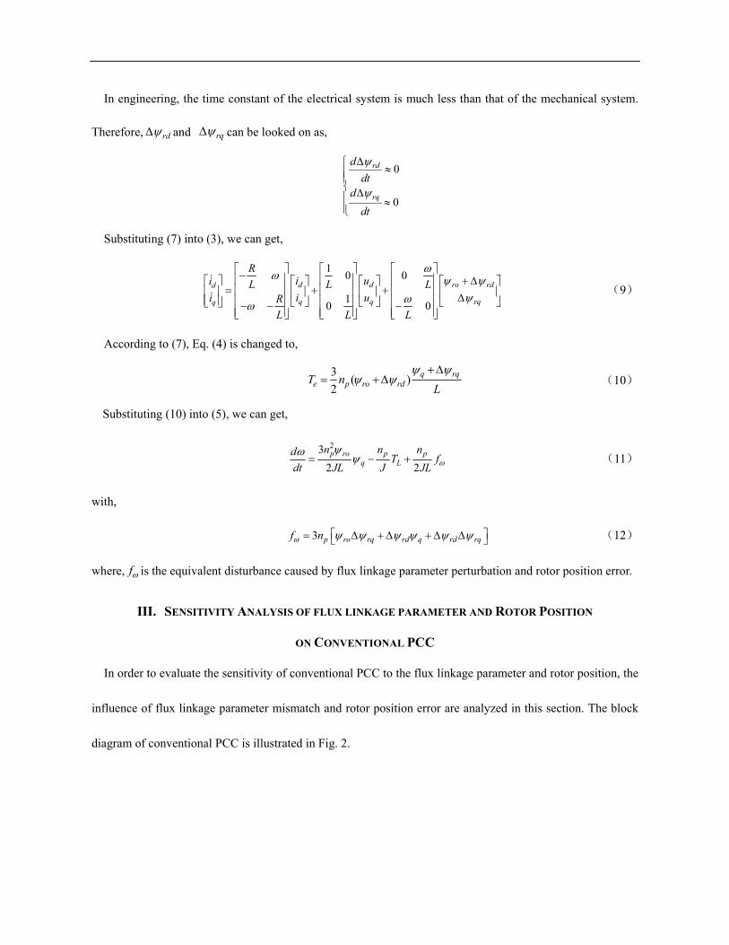
In engineering, the time constant of the electrical system is much less than that of the mechanical system.
Therefore, rd and rq can be looked on as,
0
0
rd
rq
d
dtd
dt
Substituting (7) into (3), we can get,
10 0
10 0
d d ro rdd
q q rqq
Ri ui L L Li ui R
L L L
(9)
According to (7), Eq. (4) is changed to,
3( )
2q rq
e p ro rdT nL
(10)
Substituting (10) into (5), we can get,
23
2 2 p ro p p
q L
n n ndT f
dt JL J JL (11)
with,
3 p ro rq rd q rd rqf n
(12)
where, f is the equivalent disturbance caused by flux linkage parameter perturbation and rotor position error.
III. SENSITIVITY ANALYSIS OF FLUX LINKAGE PARAMETER AND ROTOR POSITION
ON CONVENTIONAL PCC
In order to evaluate the sensitivity of conventional PCC to the flux linkage parameter and rotor position, the
influence of flux linkage parameter mismatch and rotor position error are analyzed in this section. The block
diagram of conventional PCC is illustrated in Fig. 2.

PI( )dqu k( 1)ref
dqi k
( )dqi k
PCC
( )k
PMSM
( )abci k
( )k
dq
abc
ref
( )k
SV-PWM
Fig. 2. Block diagram of the conventional PCC.
The output voltage vectors of the PCC are expressed by [18],
1( ) [ ( 1) ( ) ( ) ( )]k k k i k k refu F i G P (13)
where, ( 1)
( 1)( 1)
refd
refq
i kk
i k
refi ,( )
( )( )
d
q
i kk
i k
i ,( )
( )( )
d
q
u kk
u k
u ,0
0
s
s
T
LT
L
F ,1 ( )
( )
( ) 1
s s
s s
RT T k
LkR
T k TL
G
,
0( )
( )ros
kT k
L
P
.
According to (9), the discrete model of the PMSM under flux linkage parameter perturbation and rotor
position error can be expressed by,
( 1) ( ) ( ) ( ) ( )k k k k k i G i F u P (14)
where,( )
( )
( ) ( )
rqs
ro rds s
T kLk
T k T kL L
P
.
For sampling delay, the conventional PCC method employed in the practical application belong to one beat
delay control. At the ( 1) sk T moment, the voltage vector ( )ku is applied to the PMSM. Therefore, substituting
(13) into (14) yields,
( 1) ( 1) ( 1)refd ddi k i k i k
(15)
( 1) ( 1) ( 1)refq q qi k i k i k
(16)
with
(1 )sin( )( 1) ( ) ( )
(1 )cos( ) 1( 1) ( ) ( )
rqd s ro s
rdq s ro s
i k T k T kL L
i k T k T kL L
(17)
From (15) and (16), it can be found that there exits an error between the current response value and the current

reference value under flux linkage parameter perturbation and rotor position error. According to (17), the current
error is related to the speed, the flux linkage parameter perturbation rate and the rotor position error. The PMSM
is uncontrollable if the rotor position error range exceeds 5 。[23]. Therefore, in the case of the rotor position
allowable error range (i.e. 5 。), the influence of rotor position error on PCC is analyzed in this paper.
The motor parameters are shown in table I. The d-and q-axis current errors are plotted under flux linkage
parameter perturbation and rotor position error, as shown in Fig. 3 and 4. Fig. 3 shows the d- and q-axis current
errors under flux linkage parameter mismatch. The q-axis current response value is greater than its reference,
but the flux linkage parameter mismatch does not affect the d-axis current. Fig. 4 shows the relationship between
the current error and the speed under flux linkage parameter mismatch and rotor position error. When the rotor
position error range is positive, the d-and q-axis response current is greater than the current reference. When the
rotor position error range is negative, the q-axis response current is greater than the current reference, and the
d-axis response current is less than the current reference. The q-axis current error increase with the increase of
speed under flux linkage parameter perturbation and rotor position error. Through the analysis above, it can be
concluded that the q-axis current of conventional PCC is mostly sensitive to rotor position and flux linkage
parameters, while the influence of d-axis current can be neglected.
Fig. 3. d-and q-axis current errors under flux linkage parameter mismatch.

Fig. 4. d-and q-axis current errors under flux linkage parameter mismatch and rotor position error.
IV. PREDICTIVE STATOR FLUX CONTROL
According to (9), (10) and (11), we can express the state equations of the PMSM as follows when flux linkage
parameter mismatch and rotor position error occur.
1
ψ a
ψ
xAx Bu Cf Df
x Ex f
d
dt
(18)
where,d
q
x
, 1
d
q
i
i
x
,d
q
q
u
u
u
, 0
0
ro
ψf
,and
2
rd
rq
Lf
TL
af
are state variables, system inputs, system
outputs, PM flux linkage, and fault function, respectively.
The coefficient matrixes of the state equations are
0
0
0 0 0
R
LR
L
A
,2
1 0 0
0 1 0
30 0
2p ron
JL
B
,
0 0
0 0 0
0 0 0
R
L
C ,
0 0
0 0
0 0pn
J
D
,
0 0
0 0
0 0 1
L
L
E , respectively.
The discrete expression of (18) is,
1 1( ) ( ) ( 1)
( )( ) ( )
( ) ( )1 1 ( )( ) ( ) ( 1)
( ) ( )0
( ) ( )0 0
d rorqd ds s
q q rdq
s s
d d ro
q q
R Rk k
ku k kL T T L
u k kR kk k
L T T
k i kL
k i kL
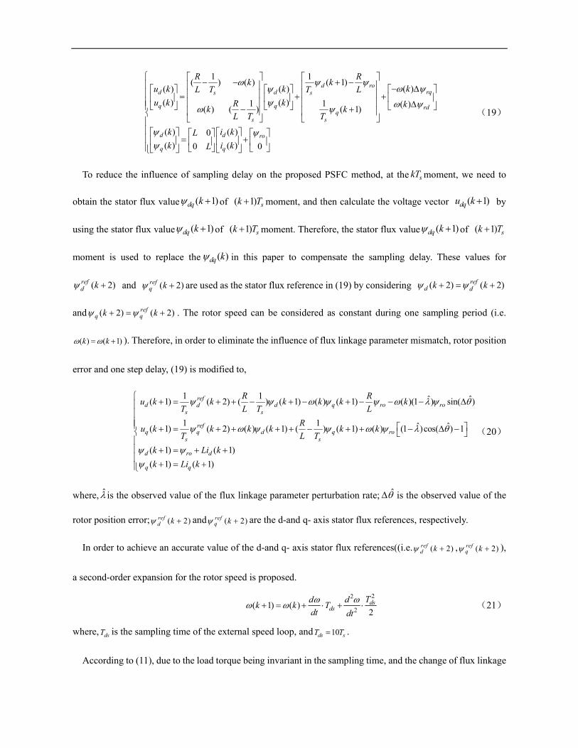
(19)
To reduce the influence of sampling delay on the proposed PSFC method, at the skT moment, we need to
obtain the stator flux value ( 1) dq k of ( 1) sk T moment, and then calculate the voltage vector ( 1)dqu k by
using the stator flux value ( 1) dq k of ( 1) sk T moment. Therefore, the stator flux value ( 1) dq k of ( 1) sk T
moment is used to replace the ( )dq k in this paper to compensate the sampling delay. These values for
( 2)refd k and ( 2)ref
q k are used as the stator flux reference in (19) by considering ( 2) ( 2)refd dk k
and ( 2) ( 2)refq qk k . The rotor speed can be considered as constant during one sampling period (i.e.
( ) ( 1)k k ). Therefore, in order to eliminate the influence of flux linkage parameter mismatch, rotor position
error and one step delay, (19) is modified to,
1 1 ˆ ˆ( 1) ( 2) ( ) ( 1) ( ) ( 1) ( )(1 ) sin( )
1 1 ˆ ˆ( 1) ( 2) ( ) ( 1) ( ) ( 1) ( ) (1 )cos( ) 1
( 1) ( 1)
( 1) ( 1)
refd d q ro rod
s s
refq q d q ro
s s
d ro d
q q
R Ru k k k k k k
T L T L
Ru k k k k k k
T L T
k Li k
k Li k
(20)
where, is the observed value of the flux linkage parameter perturbation rate; ˆ is the observed value of the
rotor position error; ( 2)refd k and ( 2)ref
q k are the d-and q- axis stator flux references, respectively.
In order to achieve an accurate value of the d-and q- axis stator flux references((i.e. ( 2)refd k , ( 2)ref
q k ),
a second-order expansion for the rotor speed is proposed.
22
2( 1) ( )
2
dsds
Td dk k T
dt dt (21)
where, dsT is the sampling time of the external speed loop, and 10ds sT T .
According to (11), due to the load torque being invariant in the sampling time, and the change of flux linkage

components being slow, therefore, 0LdT
dtand 3
qp rd
ddfn
dt dt, one yields
22
2
33
2
p ro q qp rd
n d ddn
JL dt dtdt (22)
Substituting(11) and (22) into(21), we can get,
2 2 23 3 ( ) ( 1)( 1) ( ) ( ) 3
2 2 2 2
p ro p p p ro q q dsq L ds p rd
ds
n n n n k k Tk k k T f T n
JL J JL JL T
(23)
Taking ( )refq k and ref as the references of ( )q k and ( 1)k , respectively, the following equation can
be obtained from (23),
2
2
ˆ3 6 ˆˆ( ) ( 1)4 2( )
ˆ9 6
4
p ro ds p rd ds p ds p dsrefq L
refq
p ro ds p rd ds
n T JLn T n T n Tk k T f
JL J JLkn T JLn T
JL
(24)
where, ( )refq k and ref are the stator flux reference and speed reference, respectively;
ˆ ˆˆ (1 )cos( ) 1rd ro ; LT and f are the observed values of the load torque and unknown external
disturbances, respectively.
Then, the stator flux reference is calculated using Lagrange extrapolation under ( ) 0refdi k , as expressed by,
( 2) ( 1) ( ) ( )
( 2) 3 ( ) 3 ( 1) ( 2)
ref ref ref refro rod d d d
ref ref ref refq q q q
k k k Li k
k k k k
(25)
d dt
Predictive Stator Flux Control
(20)
dq
SV-PWM
PMSM
Clarke
Park
( )k( )k
( )k
Predictive Stator Flux
Control(24)
Composite Discrete Time SMO
(31)~(38)
ref
( 1)u k
( )u k
( )i k( )dqi k
( )dqu k
( 2)refq k
( 1)dqu k
Lag
( )refq k
( 2)refd k
( 1)dqi k
f
ˆLT
Lag
Fig. 5. Block diagram of the PMSM drive system with PSFC method.
The block diagram of the PMSM drive system with PSFC method is shown in Fig. 5. The proposed PSFC
method is used to substitute conventional PCC to overcome the influence of flux linkage parameter mismatch,

rotor position error and one step delay.
V. DESIGN OF COMPOSITE DISCRETE TIME SMO
The key to realizing PSFC method is to estimate the flux linkage parameter perturbation rate, rotor position
error, and load torque. The composite discrete time SMO can simultaneously estimate these unknown factors.
Based on (18), the composite SMO is designed as follows,
1
ˆˆ sgn( )
ˆ ˆ
ψ
ψ
xAx Bu Cf Me H e
x Ex f
d
dt
(26)
where, x is the observed value of x ; sgn() is the sliding mode control function; M and H are the designed gain
matrixes of composite SMO.
The time-varying sliding surface is defined as,
1
21 1
3
ˆˆ
ˆ ˆˆ ˆ( )
ˆ ˆ
d d d d
q q q q
i ie
e i i
e
e x x E x x E
The dynamic equation considering the estimation error is obtained by subtracting (18) from (26),
sgn( ) ae
Ae Df Me H ed
dt (27)
A. Stability Analysis of the Proposed Composite SMO
In order to analyze the asymptotic stability of the proposed composite SMO, the following Lyapunov
candidate function is defined,
1
2TV e e
(28)
Differentiating (28) and combining (27), one yields.
sgn( )
sgn( )
a
a
Ve Ae Df Me H e
e A M e e Df e H e
T
T T T
d
dt
(29)

where, M and H are designed as
0 1 0
1 0 0
0 0 0
M and1
2
3
0 0
0 0
0 0
h
h
h
H , respectively.
Simplifying (29) yields,
2 21 2
1 1 1 2 2 2
3 3 3
sgn( )
sgn( )
( )2
a
a
Ve Df e H e
e Df e H e
T T
T T
rq rd
pL
d R Re e
dt L L
e h e e h e
n fT e h e
J L
(30)
In engineering, the fault function af is bounded, that is, 1rd N , 2rq N , 32Lf
T NL
, where, N1, N2,
N3 are the boundary values. If H satisfies 1 2 rqh N , 2 1 rdh N , 33 ( )
2p p
L
n N n fh T
J J L
, then
0V . Therefore, the stability and convergence of the composite SMO is guaranteed. When the composite SMO
is stable, the observed value will converge to the actual value.
B. Expression of Composite Discrete Time SMO
Since the proposed PSFC is computed at discrete instants, it is necessary to deduce the discrete expression of
the composite SMO. If the sampling period is short enough, the composite discrete time SMO can be expressed
by (31) according to (26).
2 1 1
1 2 2
2
3
ˆ ˆ ˆ( 1) 1 ( ) ( ) ( ) ( ) ( ) ( ) ( ) sgn( ( ))
ˆ ˆ ˆ( 1) 1 ( ) ( ) ( ) ( ) ( ) ( ) ( ) sgn( ( ))
3ˆ ˆ( 1) ( ) ( )
2
d s d s q s d s ro s s
q s q s d s q s s
p ro sq
R Rk T k k T k T u k T k T e k h k T e k
L L
Rk T k k T k T u k k T e k h k T e k
L
n Tk k k h
JL 3( ) sgn( ( ))
sk T e k
(31)
C. Estimation of Flux Linkage Parameter Perturbation Rate, Rotor Position Error, Equivalent Disturbance and Load Torque
According to (27), when the system reaches the sliding mode surface, that is 0 e ed dt , the discrete form
of fault function is obtained as follows,

( ) sgn( ( ))k kaDf H e (32)
From (32), the estimated load torque and new flux-linkage components are obtained.
2 2
1 1
3 3
ˆ sgn( ( ))
ˆ sgn( ( ))
ˆ( )ˆ sgn( ( ))2
rd
rq
Lp
h e k
h e k
fJ kT h e k
n L
(33)
From (12), the equivalent disturbance is expressed as,
ˆ ˆ ˆ ˆ ˆ3 ( )p ro rq rd q rd rqf n k
(34)
In order to eliminate the chattering of the sign function, the sign function is replaced with a hyperbolic tangent
function with smooth continuity. The hyperbolic tangent function is defined as,
1
1
esgn tanh
e
(35)
where, is a coefficient of regulation, and must be greater than zero.
According to (33) and Fig. 1, we can deduce the following equations for the rotor position error and PM flux
linkage parameter.
1 rq
ro rd
ˆˆ tan
ˆ
(36)
ˆˆ
ˆsin( )
rqr
(37)
According to (6), flux linkage parameter perturbation rate is expressed by
ˆˆ ro r
ro
(38)
VI. SIMULATIONS
The parameters of PMSM used in the simulation are shown in tables I. The sampling frequencies for current
control loop and speed control loop are 10kHz and 1kHz, respectively; the proposed composite discrete time
SMO parameters are 1 2.5h , 2 1.5h , 3 50h and 2 .At 0s, the speed reference steps from 0 to 800rad/s. And
at0.4 and 0.6s, the load torque is increased suddenly from no-load to rated load and decreased from rated load

to no-load, respectively.
Table I: MAIN PARAMETERS OF SPMSM
Parameters Value
Rated power 125kW
Rated speed 2000r/min
Rate torque 600N.m
Stator phase resistance(R) 0.02Ω
Number of pole pairs (np) 4
Inductances(L) 1mH
Flux linkage of PM (Ψro) 0.892Wb
Rotational inertia (J) 1.57kg.m2
Type of magnet NdFeB
Magnet coercivity 889kA/m
Operating temperature 20°C
A. Simulation for PMSM under flux linkage parameter mismatch( 0.5 )
In this simulation, the control performance comparison between conventional PCC and proposed PSFC under
flux linkage parameter mismatch are investigated. The simulation results of the conventional PCC and the
proposed PSFC are shown in Fig. 6 and Fig. 7, respectively.
eT
ai
qirefqi
di
refdi
(a) (b)
Fig. 6. Simulation results of the conventional PCC. (a) the phase current, speed and torque. (b)d-and q-axis current.
From Fig. 6, it can be seen that the q-axis current response is larger than the current reference in the transient
process. In addition, an apparent static error between q-axis current response and the current reference can be
observed. According to the simulation results, it can be observed that flux linkage parameters mismatch has
effect on current response in conventional PCC method. Compared with the conventional PCC method, the
proposed PSFC method can achieve a lowest level of torque ripple as shown in Fig. 7(a).The reason is that the

composite discrete time SMO employed in the proposed PSFC can significantly suppress the flux linkage
parameter mismatch.
eT
ai q ref
q
d
refd
(a) (b)
Fig. 7. Simulation results of the proposed PSFC. (a) the phase current, speed and torque. (b) d-and q-axis stator flux
linkage.
Fig. 8 depicts the three-dimensional rotor flux trajectories of the conventional PCC and proposed PSFC under
flux linkage parameter mismatch. The stator flux linkage error of conventional PCC and proposed PSFC are
3.4% and 1.5%, respectively. The static error of q-axis current in Fig. 6(b), is responsible for the large flux
linkage error in Fig. 8(a). While in the proposed PSFC, the flux linkage error is drastically reduced for the reason
that it can track the stator flux reference accurately. The frequency spectra of the conventional PCC and proposed
PSFC under rated load conditions are illustrated in Fig. 9. With Fourier analysis, the stator current THD of
conventional PCC under flux linkage parameter mismatch is 10.96%. While, it is reduced to 7.91% when the
proposed PSFC is applied. The torque ripple decreases from 5.5% to 4.4%. Fig. 10 shows the reference and
estimated values of flux linkage. According to Eq. (27), the error equation of the composite discrete time SMO
is based on d- and q-axis current. In the process of motor start-up, the d-and q-axis current are not stable, and
the observed values of d-and q-axis current deviate greatly from the actual values. Therefore, there is a large
estimation error in the initial load torque observation. The results reflect that the proposed composite discrete
time SMO can accurately estimate the flux linkage parameter perturbation rate, rotor position error, disturbance,
and load torque when the motor runs to steady state.

(a) (b)
Fig. 8. The three-dimensional rotor flux trajectories. (a) Conventional PCC. (b) Proposed PSFC.
(a) (b)
Fig. 9. The frequency spectra of the stator current ia at rated load.(a) Conventional PCC. (b) Proposed PSFC.
(a) (b)
(c) (d)
Fig. 10. Simulation results of the reference and estimated values under flux linkage parameter mismatch( =0.5). (a)
Flux linkage parameter perturbation rate. (b) Rotor position error. (c) Disturbance. (d) Load torque.

B. Simulation for PMSM under flux linkage parameter mismatch( 0.5 ) and rotor position error(
36 )
Fig. 11 and Fig. 12 show the simulated results of conventional PCC and proposed PSFC under flux linkage
parameter mismatch and rotor position error. The steady-state error exists in the q-axis current when taking the
conventional PCC method. The reason is that the conventional PCC must rely on the precise mathematical
model of the motor. From Fig. 12(b), it can be seen that the proposed PSFC method can exactly track stator flux
linkage references under the flux linkage parameter mismatch and rotor position error. Moreover, it also can be
seen that the torque ripple and stator flux linkage error are effectively suppressed.
eT
ai
qirefqi
di
refdi
(a) (b)
Fig. 11. Simulation results of the conventional PCC. (a) the phase current, speed and torque. (b) the d-and q-axis
current.
eT
ai q ref
q
d
refd
(a) (b)
Fig. 12. Simulation results of the proposed PSFC. (a) the phase current, speed and torque. (b) d-and q-axis stator
flux linkage.
Fig. 13 depicts the three-dimensional rotor flux trajectories of the conventional PCC and proposed PSFC
under the flux linkage parameter mismatch and rotor position error. The stator flux linkage error of conventional

PCC and proposed PSFC are 3.2% and 1.8%, respectively. It can be observed that the PSFC method has
satisfying steady-state performance(smaller α-β stator flux linkage error) compared with the conventional PCC
method. The frequency spectra of the conventional PCC and proposed PSFC under flux linkage parameter
mismatch and rotor position error are illustrated in Fig. 14. Compared to the conventional PCC, the stator current
THD of proposed PSFC decreases from 7.99% to 7.42% under flux linkage parameter mismatch and rotor
position error. The peak-to-peak torque ripple decreases from 5.4% to 4.5%, while the tracking time of the two
control methods is almost the same, that’s about 39ms. Fig. 15 shows reference and estimated values of flux
linkage. It can be seen that the composite discrete time SMO based on stator flux state can simultaneously
estimate the flux linkage parameter perturbation rate, rotor position error, disturbance, and load torque in real
time.
(a) (b)
Fig. 13. The three-dimensional rotor flux trajectories. (a) Conventional PCC. (b) Proposed PSFC.
(a) (b)
Fig. 14. The frequency spectra of the stator current ia under rated load. (a) Conventional PCC. (b) Proposed
PSFC.

(a) (b)
(c) (d)
Fig. 15. Simulation results of the reference and estimated values under flux linkage parameters mismatch( 0.5 ) and
rotor position error( 36 ). (a) Flux linkage parameter perturbation rate. (b) Rotor position error. (c)
Disturbance. (d) Load torque.
VII. EXPERIMENTAL RESULTS
For the purpose of verifying the proposed PSFC algorithm, experiments were conducted at a 2.2kW SPMSM
laboratory platform, as is shown in Fig. 16. It is composed of two motors (drive and load machines), which are
controlled by TMS320LF2812 DSP and SV-DB100-1R5-2-1R, respectively. The load motor provides load
torque. The energy feedback unit can feed back the electric energy to the power grid and avoid the energy loss
caused by resistance heating. The sampling frequencies are the same as those of simulations. The per-unit (p.u.)
values of 2.2kW PMSM parameters are consistent with the simulation models. The rotor position error is
simulated by artificially adding an angle to the measurement result of the mechanical sensor. The start-up of the
experiment platform are as follows: the 380V AC power is firstly provided to the load motor. Then, the load
motor drive controller and the energy feedback unit are started simultaneously. The output torque of the load
motor is set to zero initially. Finally, the DSP controller of the SPMSM is power on to start up the SPMSM.

Fig. 16. Experimental platform of SPMSM drive.
A. Control performance comparison between Conventional PCC and Proposed PSFC under flux linkage parameter mismatch( 0.5 )
ref
ref
ref
ref
(a) (b)
Fig. 17. Experimental results of the α-β stator flux linkage under flux linkage parameter mismatch( =0.5). (a)
Conventional PCC. (b) Proposed PSFC.
(a) (b)
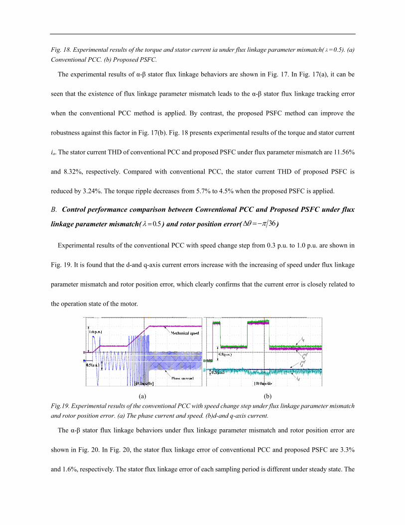
Fig. 18. Experimental results of the torque and stator current ia under flux linkage parameter mismatch( =0.5). (a)
Conventional PCC. (b) Proposed PSFC.
The experimental results of α-β stator flux linkage behaviors are shown in Fig. 17. In Fig. 17(a), it can be
seen that the existence of flux linkage parameter mismatch leads to the α-β stator flux linkage tracking error
when the conventional PCC method is applied. By contrast, the proposed PSFC method can improve the
robustness against this factor in Fig. 17(b). Fig. 18 presents experimental results of the torque and stator current
ia. The stator current THD of conventional PCC and proposed PSFC under flux parameter mismatch are 11.56%
and 8.32%, respectively. Compared with conventional PCC, the stator current THD of proposed PSFC is
reduced by 3.24%. The torque ripple decreases from 5.7% to 4.5% when the proposed PSFC is applied.
B. Control performance comparison between Conventional PCC and Proposed PSFC under flux
linkage parameter mismatch( 0.5 ) and rotor position error( 36 )
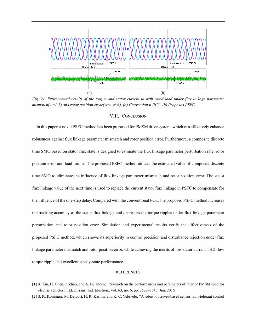
Experimental results of the conventional PCC with speed change step from 0.3 p.u. to 1.0 p.u. are shown in
Fig. 19. It is found that the d-and q-axis current errors increase with the increasing of speed under flux linkage
parameter mismatch and rotor position error, which clearly confirms that the current error is closely related to
the operation state of the motor.
di
refdi
refqi
qi
(a) (b)
Fig.19. Experimental results of the conventional PCC with speed change step under flux linkage parameter mismatch
and rotor position error. (a) The phase current and speed. (b)d-and q-axis current.
The α-β stator flux linkage behaviors under flux linkage parameter mismatch and rotor position error are
shown in Fig. 20. In Fig. 20, the stator flux linkage error of conventional PCC and proposed PSFC are 3.3%
and 1.6%, respectively. The stator flux linkage error of each sampling period is different under steady state. The

maximum and minimum errors are 1.9% and 1.3%, respectively, when taking the proposed PSFC. While, the
maximum and minimum errors are 3.8% and 2.8% when taking the conventional PCC. The flux linkage error
variation amplitude of the proposed PSFC method is only 0.6%, which verifies the effectiveness of the proposed
PSFC. The torque and stator current ia under flux linkage parameter mismatch and rotor position error are shown
in Fig. 21. The stator current THD of proposed PSFC is 9.76%, the conventional PCC is 10.32%, and it is also
lower than that of the conventional PCC. Compared with traditional PCC, the stator current THD of proposed
PSFC is only reduced by 0.56% in the case of flux parameter mismatch and rotor position error, but the stator
flux tracking accuracy is improved. Furthermore, the torque ripple is reduced from 5.3% to 4.7%.
ref
ref
ref
ref
(a) (b)
Fig. 20. Experimental results of the α-β stator flux linkage under flux linkage parameter mismatch( =0.5) and rotor
position error( 36 ). (a) Conventional PCC. (b) Proposed PSFC.
(a) (b)
Fig. 21. Experimental results of the torque and stator current ia with rated load under flux linkage parameter
mismatch( =0.5) and rotor position error( 36 ). (a) Conventional PCC. (b) Proposed PSFC.
VIII. CONCLUSION
In this paper, a novel PSFC method has been proposed for PMSM drive system, which can effectively enhance
robustness against flux linkage parameter mismatch and rotor position error. Furthermore, a composite discrete
time SMO based on stator flux state is designed to estimate the flux linkage parameter perturbation rate, rotor
position error and load torque. The proposed PSFC method utilizes the estimated value of composite discrete
time SMO to eliminate the influence of flux linkage parameter mismatch and rotor position error. The stator
flux linkage value of the next time is used to replace the current stator flux linkage in PSFC to compensate for
the influence of the one-step delay. Compared with the conventional PCC, the proposed PSFC method increases
the tracking accuracy of the stator flux linkage and decreases the torque ripples under flux linkage parameter
perturbation and rotor position error. Simulation and experimental results verify the effectiveness of the
proposed PSFC method, which shows its superiority in control precision and disturbance rejection under flux
linkage parameter mismatch and rotor position error, while achieving the merits of low stator current THD, low
torque ripple and excellent steady-state performance.
REFERENCES
[1] X. Liu, H. Chen, J. Zhao, and A. Belahcen, “Research on the performances and parameters of interior PMSM used for
electric vehicles,” IEEE Trans. Ind. Electron., vol. 63, no. 6, pp. 3533–3545, Jun. 2016.
[2] S. K. Kommuri, M. Defoort, H. R. Karimi, and K. C. Veluvolu, “A robust observer-based sensor fault-tolerant control

for PMSM in electric vehicles,” IEEE Trans. Ind. Electron., vol. 63, no. 12, pp. 7671–7681,Dec. 2016.
[3] G. S. Buja and M. P. Kazmierkowski, “Direct torque control of PWM inverter-fed ac motors—A survey,” IEEE Trans.
Ind. Electron., vol. 51,no. 4, pp. 744–757, Aug. 2004.
[4] T. Ohtani, N. Takada, and K. Tanaka, “Vector control of induction motor without shaft encoder,” IEEE Trans. Ind. Appl.,
vol. 28, no. 1, pp. 157–165,Jan./Feb. 1992.
[5] T. Türker, U. Buyukkeles, and A. F. Bakan, "A robust predictive current controller for PMSM drives." IEEE Trans. Ind.
Electron., vol. 63, no. 6, pp. 3906-3914, Jun. 2016.
[6] C. Shan, L. Wang, and E. Rogers. "A cascade MPC control structure for a PMSM with speed ripple minimization,"
IEEE Trans. Ind. Electron., vol. 60, no. 8, pp. 2978-2987, Jun. 2013.
[7] A. M. Aljehaimi, P. Pillay, "Novel flux linkage estimation algorithm for a variable flux PMSM,” IEEE Trans. Ind. Appl.,
vol. 54, no. 3, pp. 2319–2335, May. 2018.
[8]H. J. Ahn and D. M. Lee, “A new bump less rotor-flux position estimation scheme for vector-controlled washing
machine,” IEEE Trans. Ind. Electron., vol. 12, no. 2, pp. 466–473, Jan. 2016.
[9] Y. Xu, N. Parspour, and U. Vollmer, “Torque ripple minimization using online estimation of the stator resistances with
consideration of magnetic saturation,” IEEE Trans. Ind. Electron., vol. 61, no. 9, pp. 5105–5114,Sep. 2014.
[10] A. Gebregergis, M. H. Chowdhury, M. S. Islam, and T. Sebastian, “Modeling of permanent-magnet synchronous
machine including torque ripple effects,” IEEE Trans. Ind. Appl., vol. 51, no. 1, pp. 232–239, Feb. 2015.
[11] S. Chen, C. Namuduri, and S. Mir, “Controller-induced parasitic torque ripples in a PM synchronous motor,” IEEE
Trans. Ind. Appl., vol. 38,no. 5, pp. 1273–1281, Oct. 2002.
[12]X. Zhang ; B. Hou ; Y. Mei,“Deadbeat Predictive Current control of permanent-magnet synchronous motors with
stator current and disturbance observer,” IEEE Trans. Power Electron., vol. 32, no. 5, pp. 3818–3834, May. 2017.
[13] J. Rodas, F. Barrero, M. R. Arahal, C. Martín and R. Gregor, "Online estimation of rotor variables in predictive current
controllers: A case study using five-phase induction machines," in IEEE Trans. Ind. Electron., vol. 63,no. 9, pp. 5348-
5356, Sept. 2016.
[14] J.Yang, W. X. Zheng, S. Li, B. Wu, and M. Cheng, “Design of a prediction accuracy-enhanced continuous-time MPC
for disturbed systems via a disturbance observer,” IEEE Trans. Ind. Electron., vol. 62, no. 9, pp. 5807–5816, Jan. 2015.
[15] J. Yang, J. Su, S. Li, and X. Yu, “High-order mismatched disturbance compensation for motion control systems via a
continuous dynamic sliding mode approach,” IEEE Trans. Ind. Electron., vol. 10, no. 1, pp. 604–614,Aug. 2014.
[16] C. Zhang ; G. Wu ; F. Rong ; J. Feng ; L. Jia ; J. He ; S. Huang, “Robust fault-tolerant predictive current control
for permanent magnet synchronous motors considering demagnetization fault,” IEEE Trans. Ind. Electron., vol. 65, no.
7, pp. 5324–5534, Jul. 2017.
[17] C. K. Lin, T. H. Liu, J. Yu, L. C. Fu, and C.-F. Hsiao, “Model-free predictive current control for interior permanent-
magnet synchronous motor drives based on current difference detection technique,” IEEE Trans. Ind. Electron., vol.
61, no. 2, pp. 667–681, Mar. 2014.
[18] M. Yang, X. Lang, J. Long, and D. Xu, “A flux immunity robust predictive current control with incremental model
and extended state observer for PMSM drive,” IEEE Trans. Power Electron., vol. 32, no. 12, pp. 9267–9279, Dec. 2017.
[19] X.Zhang , L. Zhang, “Model predictive current control for PMSM drives with parameter robustness improvement,”
IEEE Trans. Power Electron, (Early Access).DOI10.1109/TPEL.2018.
2835835.
[20] H. Zhu, X. Xiao, and Y. Li, “Torque ripple reduction of the torque predictive control scheme for permanent-magnet
synchronous motors,” IEEE Trans. Ind. Electron., vol. 59, no. 2, pp. 871–877, Feb. 2012.
[21] Y. Cho, K. B. Lee, J. H. Song, and Y. I. Lee, “Torque-ripple minimization and fast dynamic scheme for torque
predictive control of permanent magnet synchronous motors,” IEEE Trans. Power Electron., vol. 30,no. 4, pp. 2182–
2190, Apr. 2015.

[22] P. Landsmann , R. Kennel, “Saliency based sensorless predictive torque control with reduced torque ripple,” IEEE
Trans. Power Electron., vol. 27,no. 10, pp. 4311–4320, Oct. 2012.
[23]J. Lara , J. Xu , A. Chandra, “Effects of rotor position error in the performance of field oriented controlled PMSM
drives for electric vehicle traction applications,” IEEE Trans. Ind. Electron., vol. 63, no. 8, pp. 4738–4751,Aug. 2016.


![Research Article Estimation of Stator Resistance and …downloads.hindawi.com/journals/jcse/2016/5781467.pdfestimation and temperature monitoring of a PMSM [], for which the performance](https://img.pdfslide.net/doc/110x75/5af175e47f8b9a572b90ca38/research-article-estimation-of-stator-resistance-and-and-temperature-monitoring.jpg)


![[G73] PMSM Document](https://img.pdfslide.net/doc/110x75/5475c6b7b4af9f29698b4589/g73-pmsm-document.jpg)