Embed Size (px)
Citation preview
. . . . . . . . . . . . . . . . . . . . . . . . .
. . . . . . . . . . . . . . . . . . . . . . . . .
. . . . . . . . . . . . . . . . . . . . . . . . .
Novel Sensors in Rieter CZ Yarn Sensors for Spinning Machines
22.6.2015 Jiří Sloupenský Rieter CZ s.r.o.
Jiří Sloupenský Rieter CZ s.r.o. 2
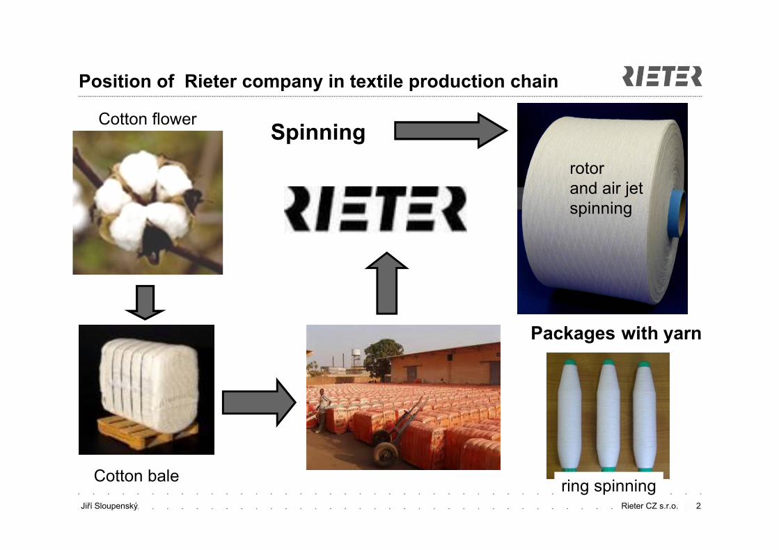
Position of Rieter company in textile production chain
Cotton flower
Cotton bale
Packages with yarn
rotorand air jet spinning
ring spinning
Spinning
Jiří Sloupenský Rieter CZ s.r.o.
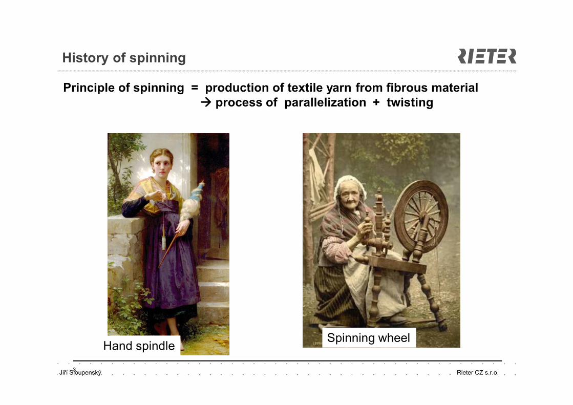
History of spinning
3
Hand spindleSpinning wheel
Principle of spinning = production of textile yarn from fibrous material process of parallelization + twisting
Jiří Sloupenský Rieter CZ s.r.o.
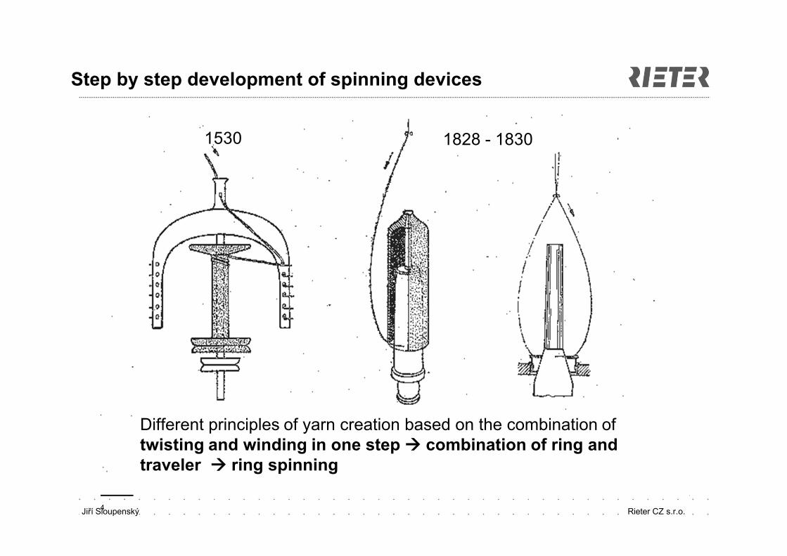
Step by step development of spinning devices
4
Different principles of yarn creation based on the combination of twisting and winding in one step combination of ring and traveler ring spinning
1530 1828 - 1830
Jiří Sloupenský Rieter CZ s.r.o.
Ring spinning principle
5
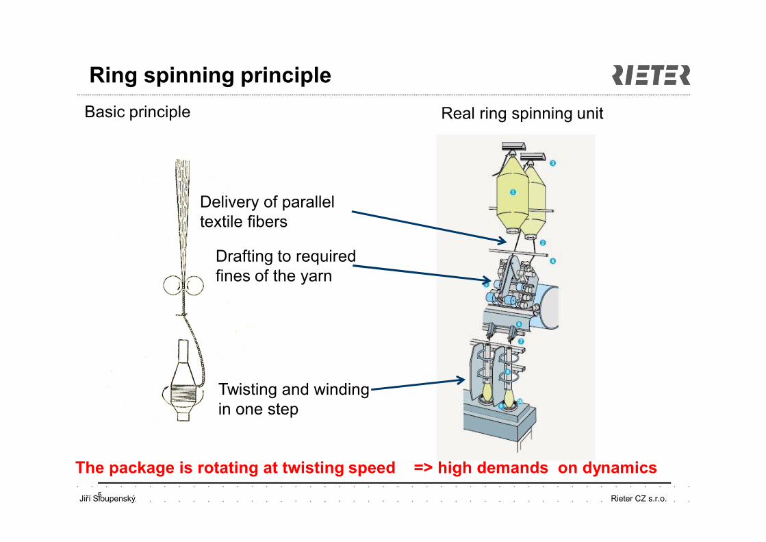
The package is rotating at twisting speed => high demands on dynamics
Basic principle Real ring spinning unit
Delivery of parallel textile fibers
Drafting to required fines of the yarn
Twisting and winding in one step
Jiří Sloupenský Rieter CZ s.r.o.
Modern ring spinning mill
6
Cívka s přízí se otáčí zákrutovou rychlostí !!!
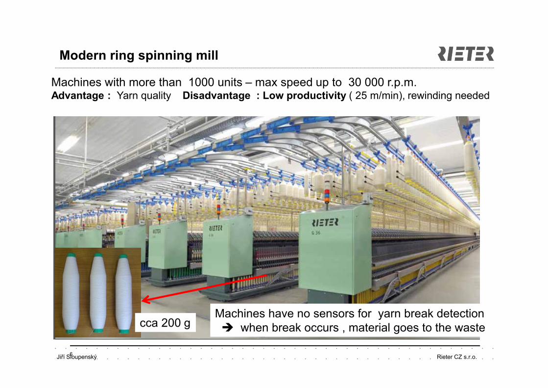
Machines with more than 1000 units – max speed up to 30 000 r.p.m.Advantage : Yarn quality Disadvantage : Low productivity ( 25 m/min), rewinding needed
Machines have no sensors for yarn break detection when break occurs , material goes to the wastecca 200 g
Jiří Sloupenský Rieter CZ s.r.o.
Rotor ( open end ) spinning principle
7
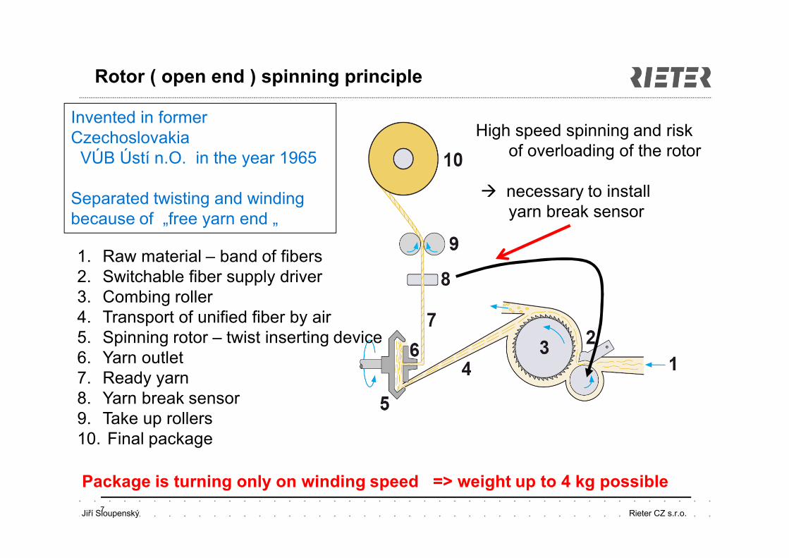
Invented in former Czechoslovakia
VÚB Ústí n.O. in the year 1965
Separated twisting and windingbecause of „free yarn end „
1. Raw material – band of fibers 2. Switchable fiber supply driver3. Combing roller4. Transport of unified fiber by air5. Spinning rotor – twist inserting device6. Yarn outlet 7. Ready yarn8. Yarn break sensor9. Take up rollers 10. Final package
Package is turning only on winding speed => weight up to 4 kg possible
High speed spinning and risk of overloading of the rotor
necessary to install yarn break sensor
Jiří Sloupenský Rieter CZ s.r.o. 8
Modern rotor spinning machines
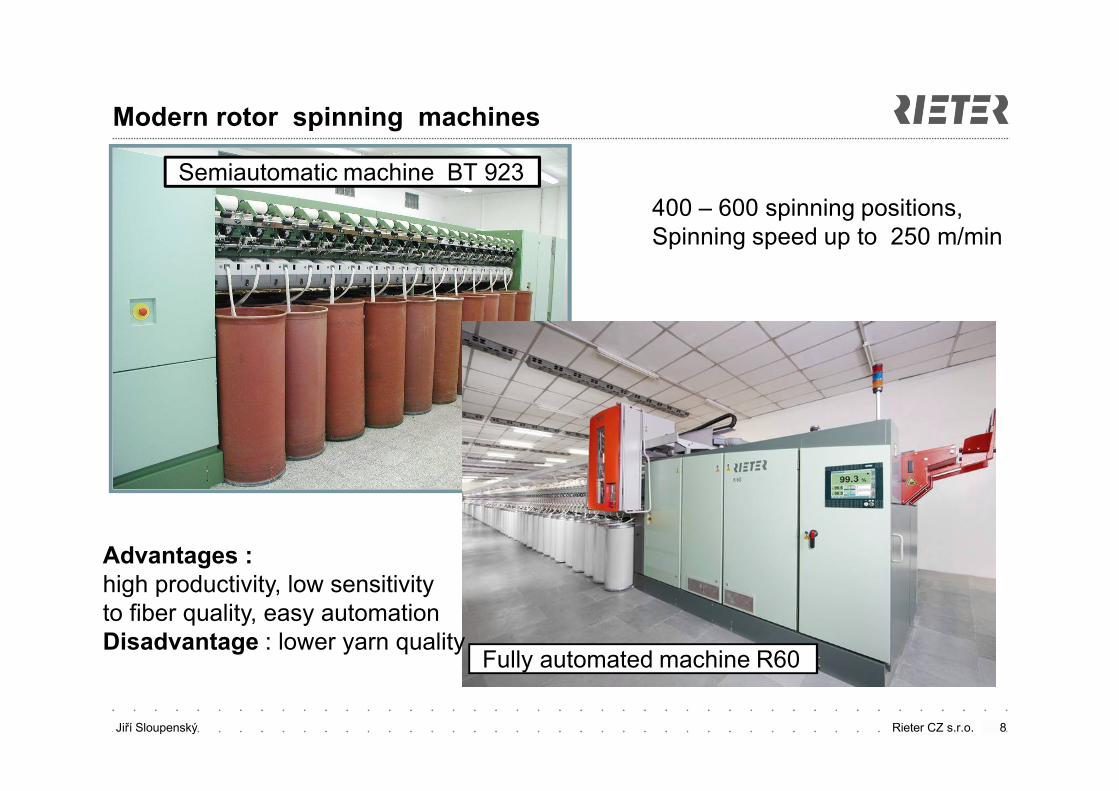
Semiautomatic machine BT 923
Fully automated machine R60
400 – 600 spinning positions,Spinning speed up to 250 m/min
Advantages : high productivity, low sensitivity to fiber quality, easy automationDisadvantage : lower yarn quality
Jiří Sloupenský Rieter CZ s.r.o. 9
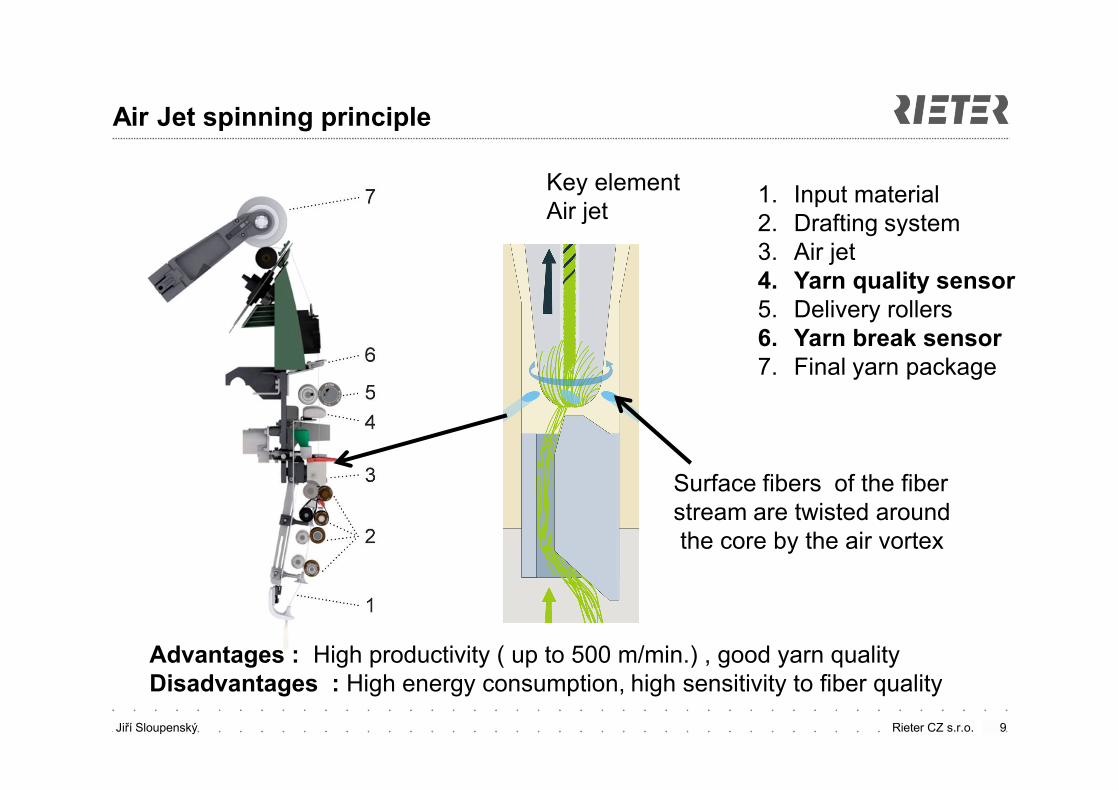
Air Jet spinning principle
1. Input material2. Drafting system3. Air jet 4. Yarn quality sensor5. Delivery rollers6. Yarn break sensor7. Final yarn package
Key elementAir jet
Surface fibers of the fiber stream are twisted aroundthe core by the air vortex
Advantages : High productivity ( up to 500 m/min.) , good yarn qualityDisadvantages : High energy consumption, high sensitivity to fiber quality
Jiří Sloupenský Rieter CZ s.r.o. 10
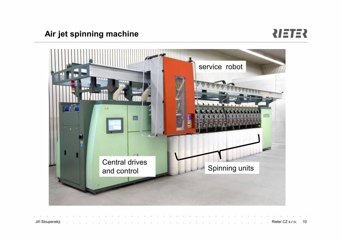
Air jet spinning machine
Spinning units Central drives and control
service robot
Jiří Sloupenský Rieter CZ s.r.o. 11
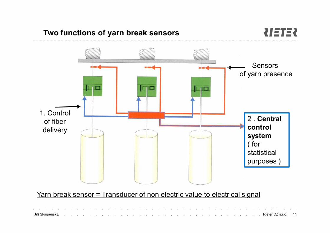
2 . Central control system ( for statistical purposes )
Sensors of yarn presence
1. Control of fiber delivery
Two functions of yarn break sensors
Yarn break sensor = Transducer of non electric value to electrical signal
Jiří Sloupenský Rieter CZ s.r.o. 12
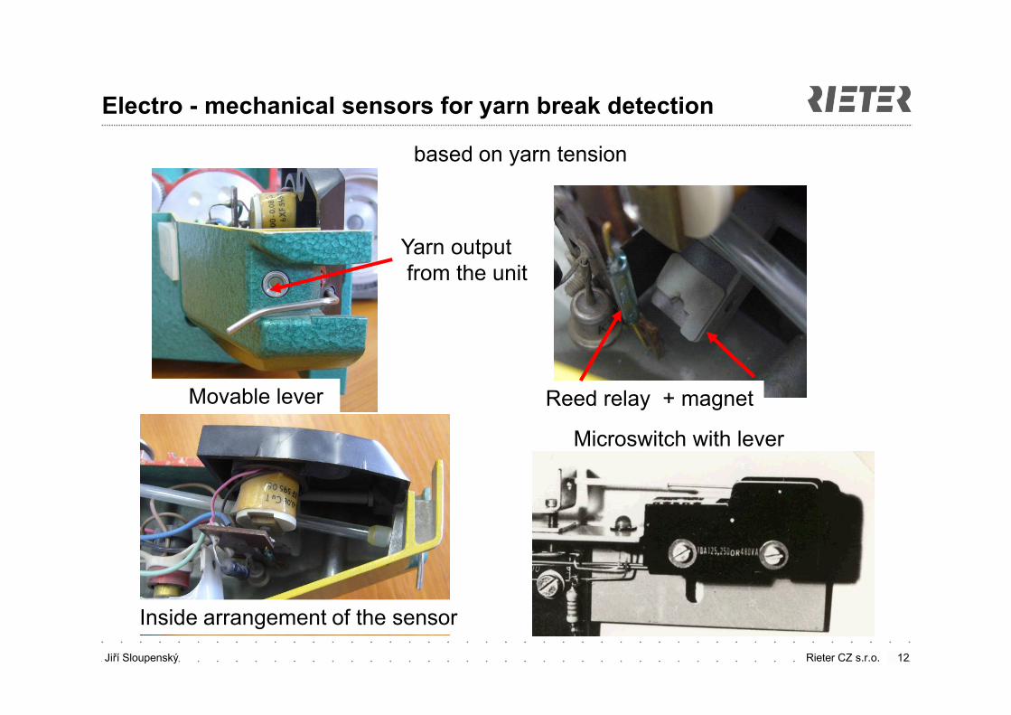
Electro - mechanical sensors for yarn break detection
based on yarn tension
Microswitch with lever
Movable lever
Inside arrangement of the sensor
Reed relay + magnet
Yarn outputfrom the unit
Jiří Sloupenský Rieter CZ s.r.o. 13
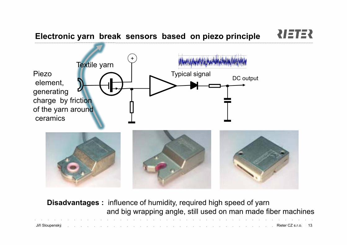
Electronic yarn break sensors based on piezo principle
Typical signalDC output
+Textile yarn
Piezoelement,
generating charge by frictionof the yarn aroundceramics
Disadvantages : influence of humidity, required high speed of yarn and big wrapping angle, still used on man made fiber machines
Jiří Sloupenský Rieter CZ s.r.o. 14
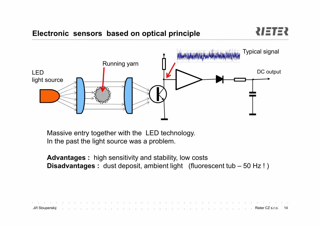
Electronic sensors based on optical principle
LED light source
Running yarn
DC output
Massive entry together with the LED technology.In the past the light source was a problem.
Advantages : high sensitivity and stability, low costs Disadvantages : dust deposit, ambient light (fluorescent tub – 50 Hz ! )
Typical signal
Jiří Sloupenský Rieter CZ s.r.o. 15
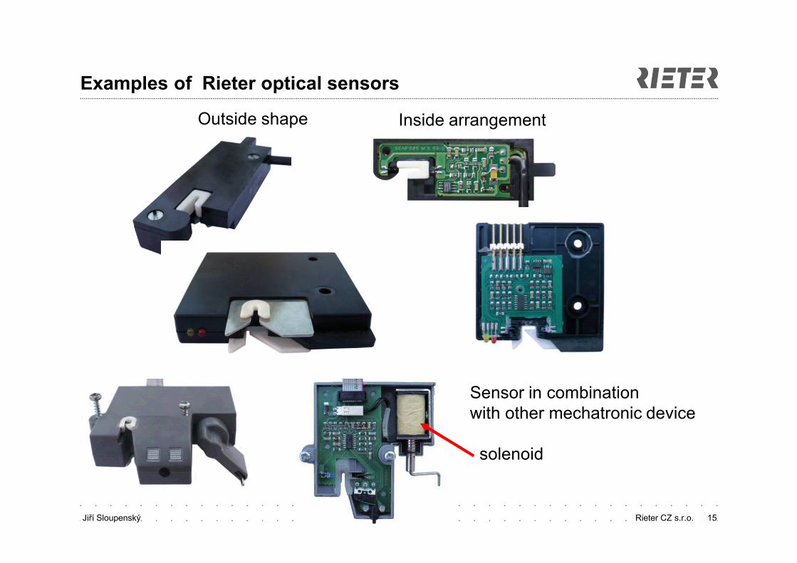
Examples of Rieter optical sensors
Outside shape Inside arrangement
Sensor in combination with other mechatronic device
solenoid
Jiří Sloupenský Rieter CZ s.r.o.
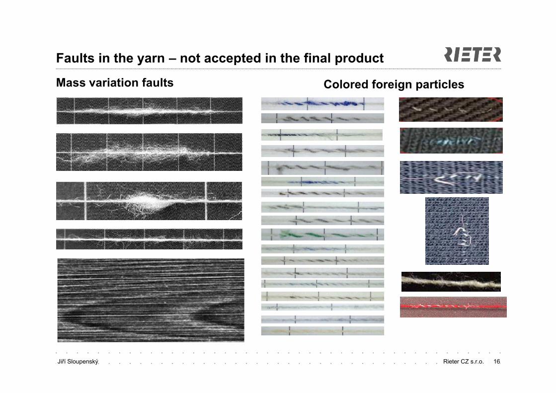
Colored foreign particles
16
Faults in the yarn – not accepted in the final product
Mass variation faults
Jiří Sloupenský Rieter CZ s.r.o.
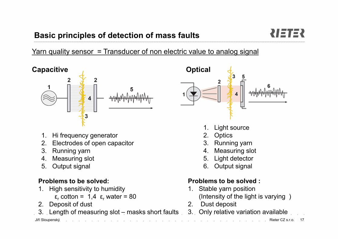
Basic principles of detection of mass faults
17
Capacitive Optical
1. Hi frequency generator2. Electrodes of open capacitor3. Running yarn4. Measuring slot5. Output signal
1. Light source2. Optics3. Running yarn 4. Measuring slot5. Light detector 6. Output signal
Problems to be solved:1. High sensitivity to humidity
εr cotton = 1,4 εr water = 802. Deposit of dust3. Length of measuring slot – masks short faults
Problems to be solved :1. Stable yarn position
(Intensity of the light is varying )2. Dust deposit 3. Only relative variation available
Yarn quality sensor = Transducer of non electric value to analog signal
Jiří Sloupenský Rieter CZ s.r.o.
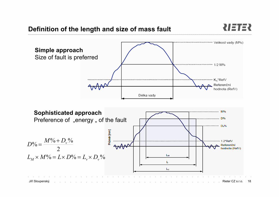
Definition of the length and size of mass fault
18
Simple approachSize of fault is preferred
%%%
2
%%%
vvM
v
DLDLML
DMD
Sophisticated approachPreference of „energy „ of the fault
Jiří Sloupenský Rieter CZ s.r.o. 19
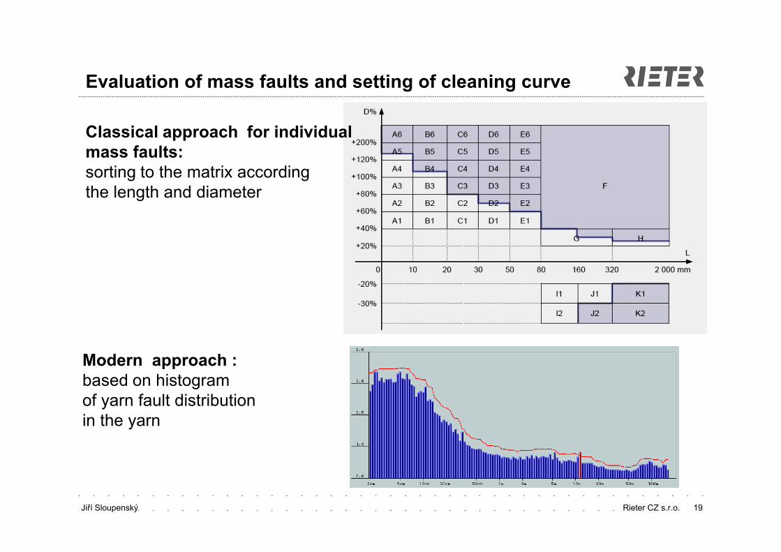
Evaluation of mass faults and setting of cleaning curve
Classical approach for individual mass faults:sorting to the matrix according the length and diameter
Modern approach : based on histogram of yarn fault distribution in the yarn
Jiří Sloupenský Rieter CZ s.r.o. 20
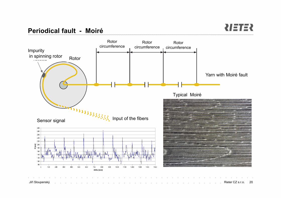
Periodical fault - Moiré
Impurityin spinning rotor Rotor
Input of the fibers
Rotorcircumference
Yarn with Moiré fault
Typical Moiré
Sensor signal
Rotorcircumference
Rotorcircumference
Jiří Sloupenský Rieter CZ s.r.o.
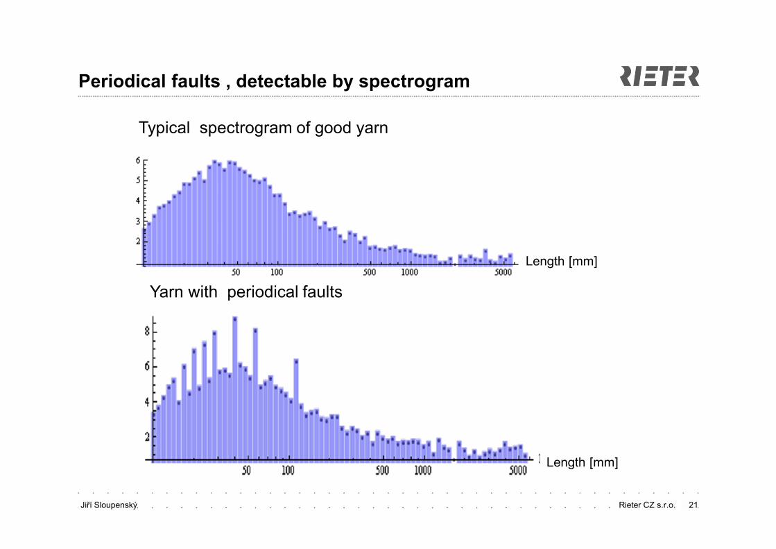
Periodical faults , detectable by spectrogram
21
Typical spectrogram of good yarn
Length [mm]
Length [mm]
Yarn with periodical faults
Jiří Sloupenský Rieter CZ s.r.o. 22
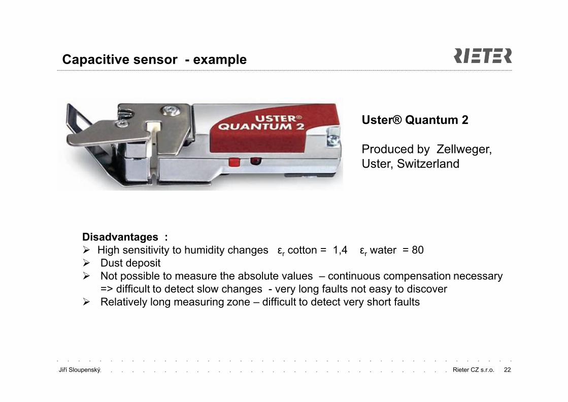
Capacitive sensor - example
Disadvantages : High sensitivity to humidity changes εr cotton = 1,4 εr water = 80 Dust deposit Not possible to measure the absolute values – continuous compensation necessary
=> difficult to detect slow changes - very long faults not easy to discover Relatively long measuring zone – difficult to detect very short faults
Uster® Quantum 2
Produced by Zellweger, Uster, Switzerland
Jiří Sloupenský Rieter CZ s.r.o. 23
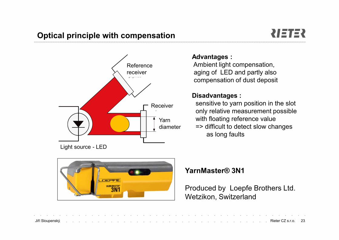
Optical principle with compensation
Advantages :Ambient light compensation,aging of LED and partly also compensation of dust deposit
Disadvantages :sensitive to yarn position in the slotonly relative measurement possiblewith floating reference value=> difficult to detect slow changes
as long faults
YarnMaster® 3N1
Produced by Loepfe Brothers Ltd.Wetzikon, Switzerland
Referencereceiver
Receiver
Yarn diameter
Light source - LED
Jiří Sloupenský Rieter CZ s.r.o. 24
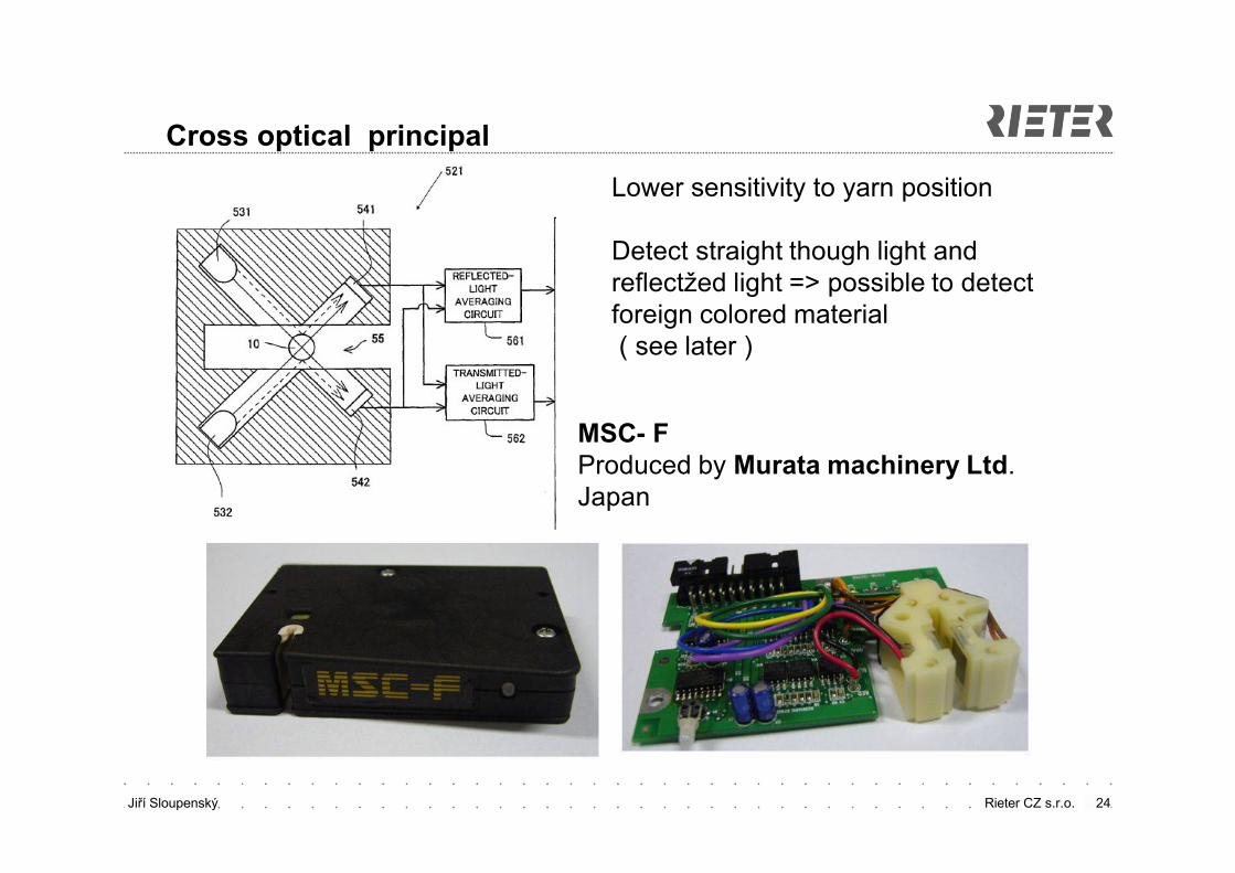
Cross optical principal
MSC- FProduced by Murata machinery Ltd. Japan
Lower sensitivity to yarn position
Detect straight though light and reflectžed light => possible to detect foreign colored material ( see later )
Jiří Sloupenský Rieter CZ s.r.o.
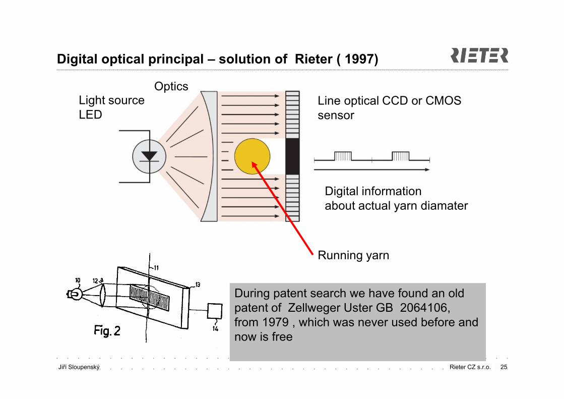
Digital optical principal – solution of Rieter ( 1997)
25
Line optical CCD or CMOS sensor
Light source LED
Optics
Digital information about actual yarn diamater
Running yarn
During patent search we have found an old patent of Zellweger Uster GB 2064106,from 1979 , which was never used before andnow is free
Jiří Sloupenský Rieter CZ s.r.o. 26
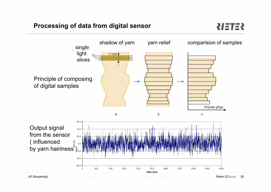
Processing of data from digital sensor
Output signal from the sensor( influenced by yarn hairiness )
Principle of composing of digital samples
shadow of yarn yarn relief comparision of samples singlelightslices
Jiří Sloupenský Rieter CZ s.r.o. 27
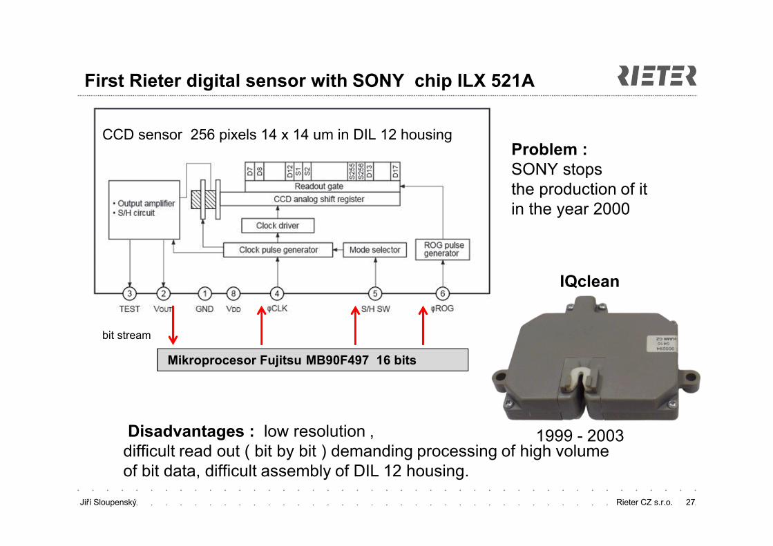
First Rieter digital sensor with SONY chip ILX 521A
Disadvantages : low resolution , difficult read out ( bit by bit ) demanding processing of high volume of bit data, difficult assembly of DIL 12 housing.
CCD sensor 256 pixels 14 x 14 um in DIL 12 housing
IQclean
1999 - 2003
Problem :SONY stops the production of it in the year 2000
Mikroprocesor Fujitsu MB90F497 16 bits
bit stream
Jiří Sloupenský Rieter CZ s.r.o.
Development of special line chips for textile sensors
Finding of replacement of the SONY chip at the market was not sucesfull( in the year 1999 )
survey of the possiblities for our own special chip
Basic requirements :
CMOS technology 1 μm optics and logics on one chip
Hither resolution ( more narrow pixel )
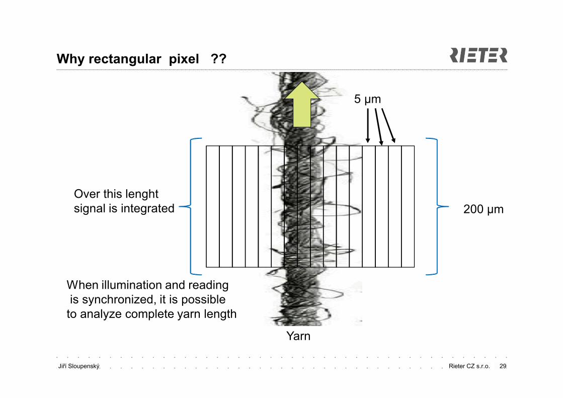
rectangular pixel for basic signal filtration ( signal integration )
integrated data pre-processing – output just a shadow size and position
integrated control of the LED
SPI communication
collaboration with ASICentrum Prague – part of SWATCH, Switzerland
28
Jiří Sloupenský Rieter CZ s.r.o.
Why rectangular pixel ??
29
Over this lenghtsignal is integrated 200 μm
5 μm
Yarn
When illumination and readingis synchronized, it is possible
to analyze complete yarn length
Jiří Sloupenský Rieter CZ s.r.o.
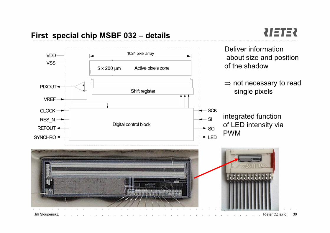
First special chip MSBF 032 – details
30
Deliver information about size and position
of the shadow
not necessary to readsingle pixels
VDD
VSS
CLOCK
RES_N
Active pixels zoneReferencepixels zone
Shift register
1024 pixel array
++
--PIXOUT
VREF
Digital control blockREFOUT
SCK
SI
SYNCHRO
SO
LED
integrated function of LED intensity viaPWM
5 x 200 μm
Jiří Sloupenský Rieter CZ s.r.o. 31
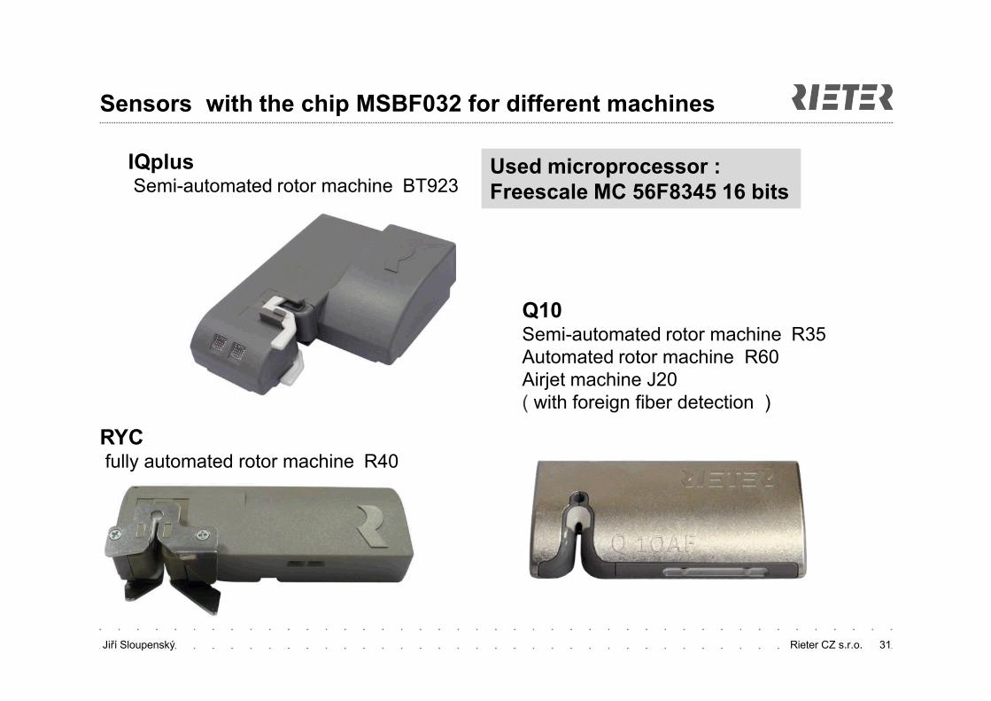
Sensors with the chip MSBF032 for different machines
IQplusSemi-automated rotor machine BT923
RYCfully automated rotor machine R40
Q10Semi-automated rotor machine R35Automated rotor machine R60Airjet machine J20( with foreign fiber detection )
Used microprocessor :Freescale MC 56F8345 16 bits
Jiří Sloupenský Rieter CZ s.r.o.
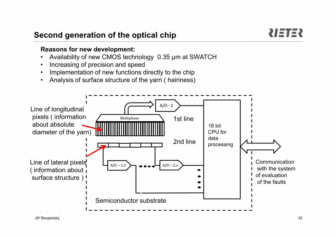
Second generation of the optical chip
32
Line of longitudinalpixels ( information about absolutediameter of the yarn)
Line of lateral pixels( information about surface structure )
Reasons for new development:• Availability of new CMOS technology 0.35 μm at SWATCH• Increasing of precision and speed • Implementation of new functions directly to the chip • Analysis of surface structure of the yarn ( hairiness)
Semiconductor substrate
18 bitCPU fordata processing
Communicationwith the system of evaluationof the faults
1st line
2nd line
Jiří Sloupenský Rieter CZ s.r.o.
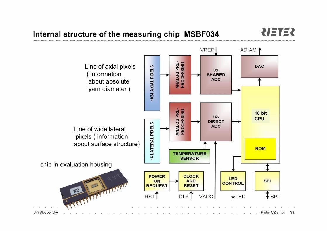
Internal structure of the measuring chip MSBF034
33
Line of axial pixels( information about absolute yarn diamater )
Line of wide lateralpixels ( information
about surface structure)
18 bitCPU
chip in evaluation housing
Jiří Sloupenský Rieter CZ s.r.o.
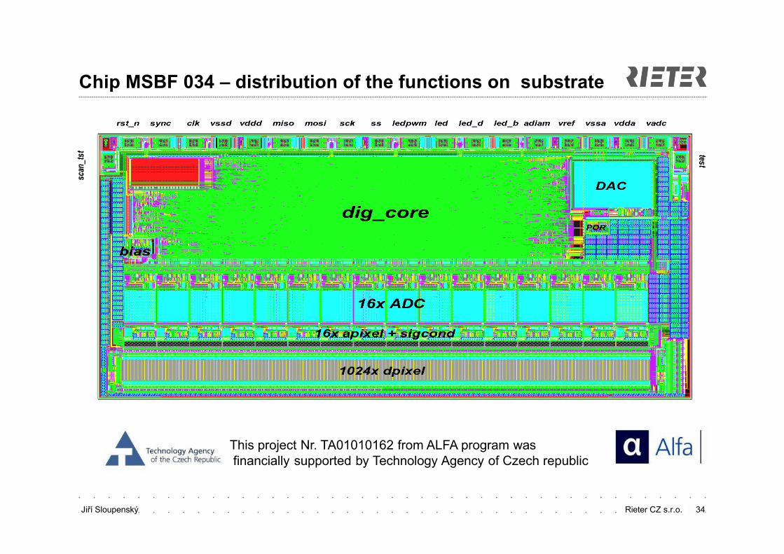
Chip MSBF 034 – distribution of the functions on substrate
34
This project Nr. TA01010162 from ALFA program wasfinancially supported by Technology Agency of Czech republic
Jiří Sloupenský Rieter CZ s.r.o.
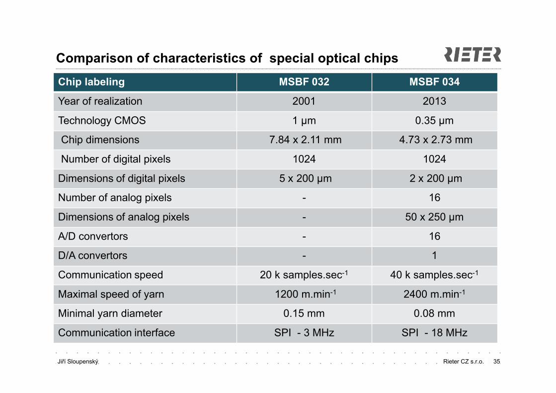
Comparison of characteristics of special optical chips
Chip labeling MSBF 032 MSBF 034
Year of realization 2001 2013
Technology CMOS 1 μm 0.35 μm
Chip dimensions 7.84 x 2.11 mm 4.73 x 2.73 mm
Number of digital pixels 1024 1024
Dimensions of digital pixels 5 x 200 μm 2 x 200 μm
Number of analog pixels - 16
Dimensions of analog pixels - 50 x 250 μm
A/D convertors - 16
D/A convertors - 1
Communication speed 20 k samples.sec-1 40 k samples.sec-1
Maximal speed of yarn 1200 m.min-1 2400 m.min-1
Minimal yarn diameter 0.15 mm 0.08 mm
Communication interface SPI - 3 MHz SPI - 18 MHz
35
Jiří Sloupenský Rieter CZ s.r.o. 36
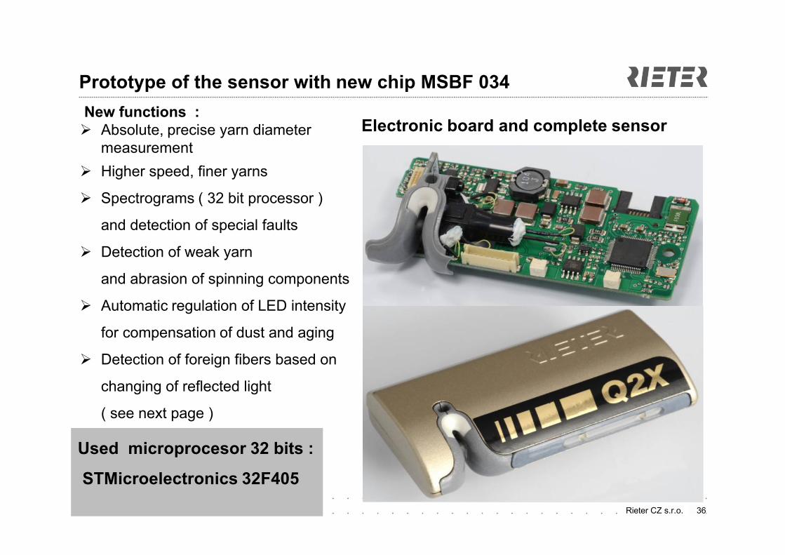
Prototype of the sensor with new chip MSBF 034
New functions : Absolute, precise yarn diameter
measurement
Higher speed, finer yarns
Spectrograms ( 32 bit processor )
and detection of special faults
Detection of weak yarn
and abrasion of spinning components
Automatic regulation of LED intensity
for compensation of dust and aging
Detection of foreign fibers based on
changing of reflected light
( see next page )
Electronic board and complete sensor
Used microprocesor 32 bits :
STMicroelectronics 32F405
Jiří Sloupenský Rieter CZ s.r.o.
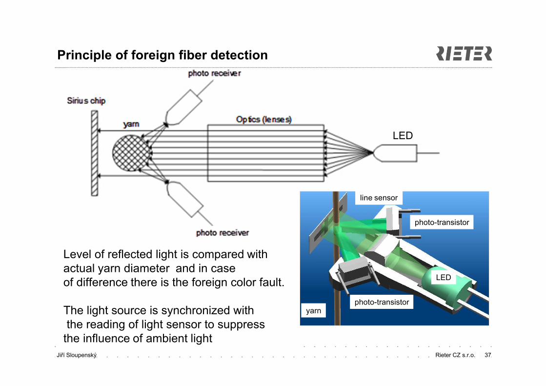
Principle of foreign fiber detection
37
LED
LED
yarn
photo-transistor
line sensor
photo-transistor
Level of reflected light is compared with actual yarn diameter and in case of difference there is the foreign color fault.
The light source is synchronized withthe reading of light sensor to suppress
the influence of ambient light
Jiří Sloupenský Rieter CZ s.r.o. 38
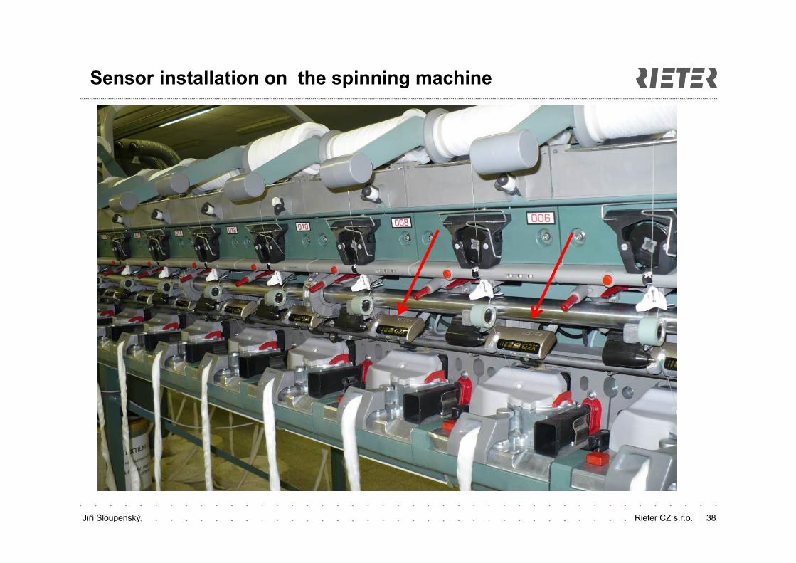
Sensor installation on the spinning machine

Jiří Sloupenský Rieter CZ s.r.o. 39
Thanks for attention
questions, remarks ?