Embed Size (px)
Citation preview
Novel Single-Drive Bearingless Motor with Wide Magnetic Gap
and High Passive Stiffness
Hiroya Sugimoto Seiyu Tanaka Akira Chiba
Tokyo Institute of Technology
1
14PESGM2609 Wednesday, July, 30, 2014
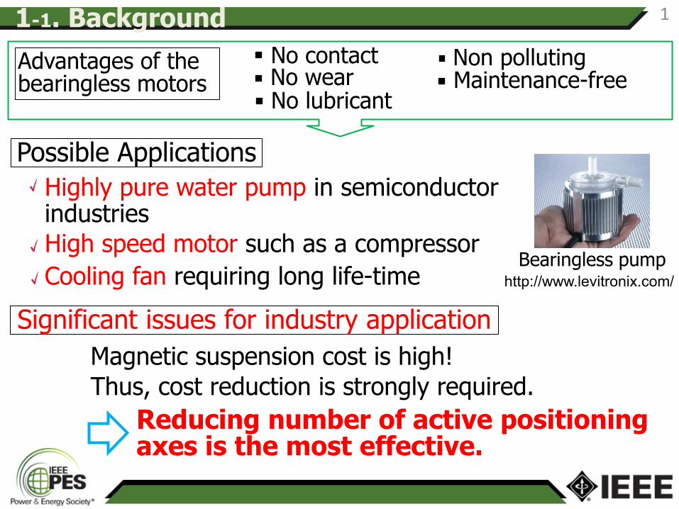
Advantages of the bearingless motors
No lubricant Maintenance-free No wear
No contact
Highly pure water pump in semiconductor industries
Non polluting
Possible Applications
Thus, cost reduction is strongly required.
High speed motor such as a compressor
Cooling fan requiring long life-time
Reducing number of active positioning axes is the most effective.
Magnetic suspension cost is high!
http://www.levitronix.com/
Significant issues for industry application
1-1. Background
Bearingless pump
1
1-2. A number of active positioning axes
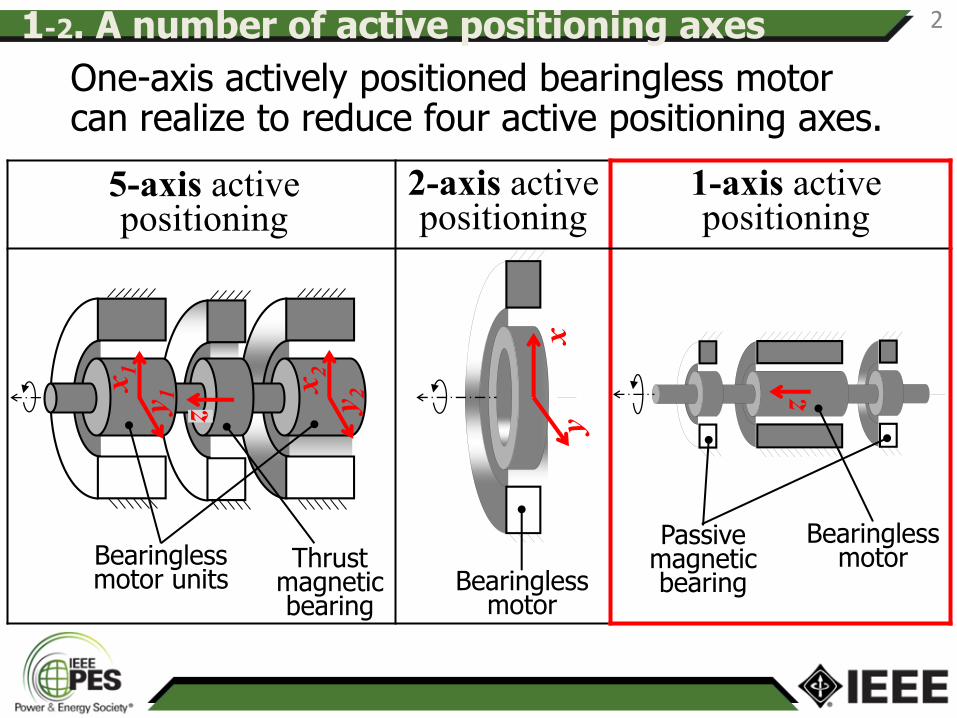
One-axis actively positioned bearingless motor can realize to reduce four active positioning axes.
xy
5-axis active positioning
2-axis active positioning
1-axis active positioning
z
x1
y 1
x2
y 2
Thrust magnetic bearing
Bearingless motor units
z
Bearingless motor
Passive magnetic bearing
2
Bearingless motor
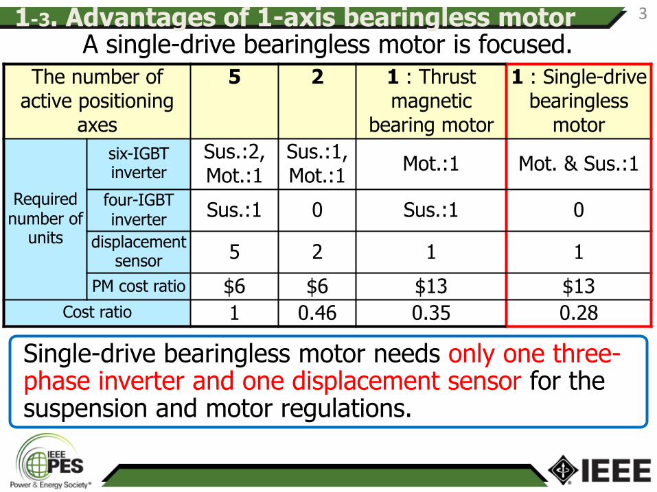
A single-drive bearingless motor is focused.
Single-drive bearingless motor needs only one three-phase inverter and one displacement sensor for the suspension and motor regulations.
The number of active positioning
axes
5 2 1 : Thrust magnetic
bearing motor
1 : Single-drive bearingless
motor
Required number of
units
six-IGBT inverter
Sus.:2, Mot.:1
Sus.:1, Mot.:1
Mot.:1 Mot. & Sus.:1
four-IGBT inverter
Sus.:1 0 Sus.:1 0
displacement sensor 5 2 1 1
PM cost ratio $6 $6 $13 $13
Cost ratio 1 0.46 0.35 0.28
1-3. Advantages of 1-axis bearingless motor 3
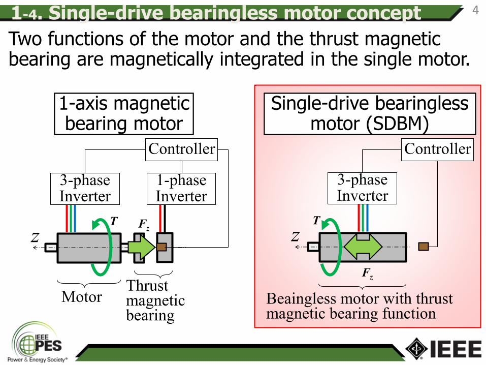
1-axis magnetic bearing motor
1-axis magnetic bearing motor
z
3-phase Inverter
Single-drive bearingless motor (SDBM)
Single-drive bearingless motor (SDBM)
Two functions of the motor and the thrust magnetic bearing are magnetically integrated in the single motor.
1-phase Inverter
Thrust magnetic bearing
Fz T
Controller
3-phase Inverter
Controller
Fz
T
z
Motor Beaingless motor with thrust magnetic bearing function
1-4. Single-drive bearingless motor concept 4
Important issues in the single-drive bearingless motor are presented.
A novel single-drive bearingless motor with wide magnetic gap and high passive stiffness is proposed.
The 3D-FEM analyses and experiment results are presented.
2. Purpose 5
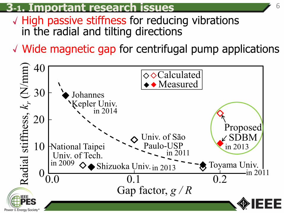
High passive stiffness for reducing vibrations in the radial and tilting directions
Wide magnetic gap for centrifugal pump applications
Univ. of São Paulo-USP
Toyama Univ.
Proposed SDBM
National Taipei Univ. of Tech.
Shizuoka Univ.
Johannes Kepler Univ.
CalculatedMeasured
Gap factor, g / R0.0 0.1 0.2
20
10
0
30
Rad
ial
stif
fnes
s, k
r(N
/mm
)
40
0
10
20
30
40
0 0.1 0.2
Rad
ial
stif
fnes
s, k
r(N
/mm
)
Gap factor, g/r
in 2014
in 2011 in 2013
in 2011 in 2013
in 2009
3-1. Important research issues 6
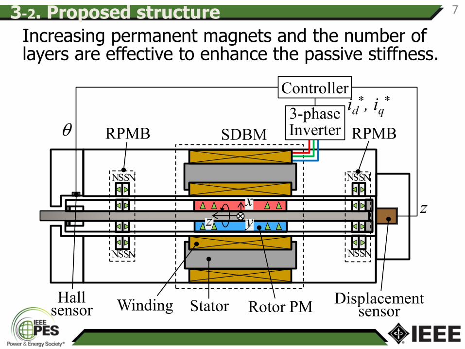
Increasing permanent magnets and the number of layers are effective to enhance the passive stiffness.
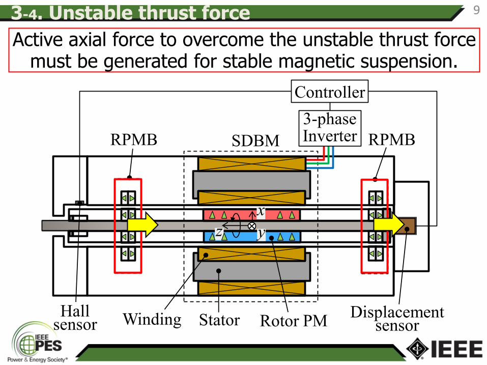
Stator Rotor PMWinding Displacement sensor
RPMB RPMBSDBM
Controller
3-phase Inverter
Hall sensor
z
x
y
id*, iq
*
z
q
3-2. Proposed structure
N N S S
N N S S N N S S
N N S S
7
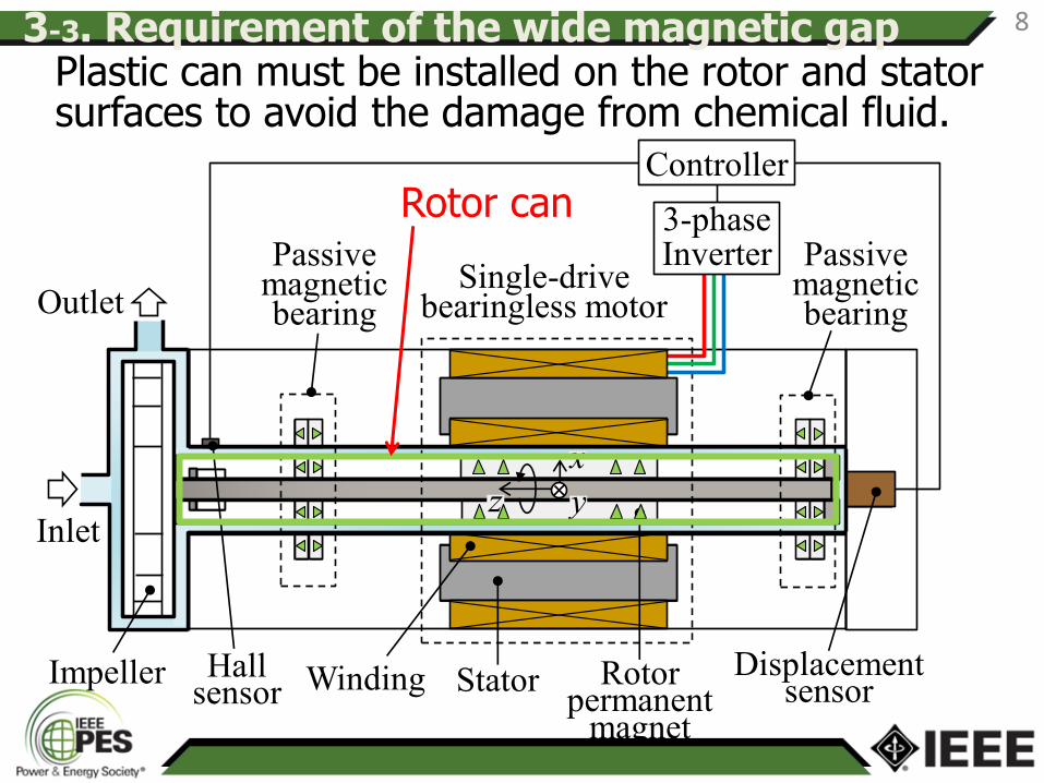
Stator Rotor permanent
magnet
Winding Displacement sensor
Passive magnetic bearing
Passive magnetic bearing
Single-drive bearingless motor
Inlet
Outlet
Impeller
Controller
3-phase Inverter
Hall sensor
z
x
y
8 3-3. Requirement of the wide magnetic gap Plastic can must be installed on the rotor and stator surfaces to avoid the damage from chemical fluid.
Rotor can
Stator Rotor PMWinding Displacement sensor
RPMB RPMBSDBM
Controller
3-phase Inverter
Hall sensor
z
x
y
Active axial force to overcome the unstable thrust force must be generated for stable magnetic suspension.
3-4. Unstable thrust force 9
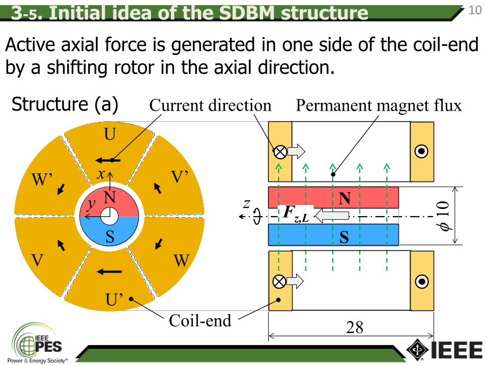
Current direction
Coil-end
Permanent magnet flux
z
S
Fz,L
f1
0
U
x
U’
N
V’
WV
W’
y
S
N
28
Active axial force is generated in one side of the coil-end by a shifting rotor in the axial direction.
3-5. Initial idea of the SDBM structure 10
Structure (a)
0
5
10
15
0 1 2 3 4 5
Ax
ial
susp
ensi
on
fo
rce,
Fz
(N)
d axis current, id (A)
Target value 7 N
0d axis current, id (A)
Axia
l su
spen
sio
n f
orc
e,
Fz
(N)
1 2 3 4 50
5
10
15
(a)
Coil ends
Rotor PM
N
S
zFz
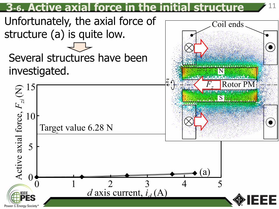
3-6. Active axial force in the initial structure 11
Unfortunately, the axial force of structure (a) is quite low.
Several structures have been investigated.
Target value 6.28 N
Act
ive
axia
l fo
rce,
Fzi
(N
)

3-7. Investigation of several structures 12
Rotor
Stator core
Winding
Current direction
d-axis
q-axis
x
y
U-coil
U-coil
S
N
z N
S
Fz,L
S
NS
U
U’
W’ V’
V W
N
x
y
A BN
S
FzM
N
S
FzL
Suspension flux
Permanent magnet flux
Rotor
Stator bars
z z
Stator yokes
Current direction
Front
Structure (b)
Structure (c)
0
5
10
15
0 1 2 3 4 5
Ax
ial
susp
ensi
on
fo
rce,
Fz
(N)
d axis current, id (A)
0d axis current, id (A)
Ax
ial
susp
ensi
on
fo
rce
Fzi
(N)
1 2 3 4 50
5
10
15
(a)(b)
(c)
(d)
Target value 6.28 NC
on
tin
uou
s ra
tin
g
Tw
ice
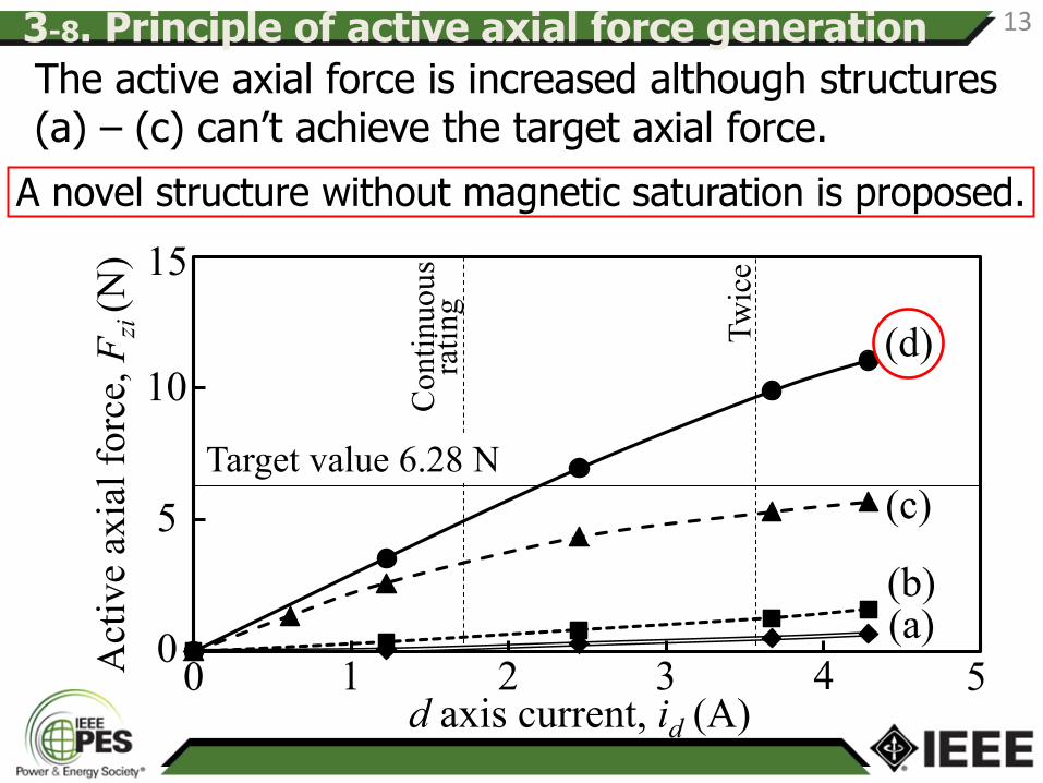
13 3-8. Principle of active axial force generation
The active axial force is increased although structures (a) – (c) can’t achieve the target axial force.
A novel structure without magnetic saturation is proposed.
Act
ive
axia
l fo
rce,
Fzi
(N
)
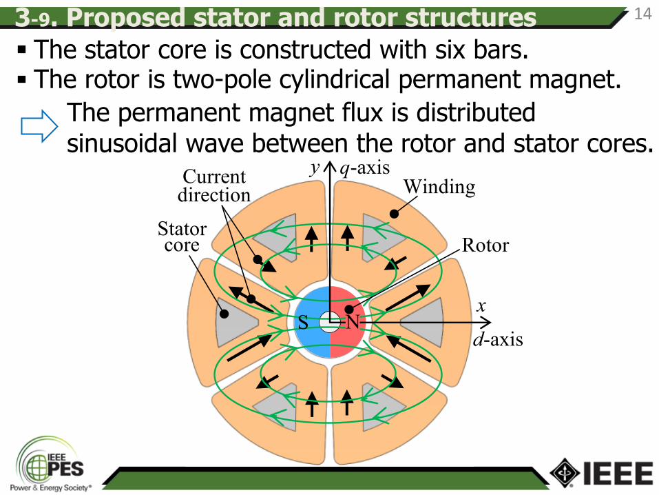
The stator core is constructed with six bars. The rotor is two-pole cylindrical permanent magnet.
The permanent magnet flux is distributed sinusoidal wave between the rotor and stator cores.
RotorStator core
WindingCurrent
direction
d-axis
q-axis
x
y
S N
3-9. Proposed stator and rotor structures 14
N
S
Fz
Suspension flux
Permanent magnet flux
Rotor
Stator
Flux strengthening
Flux weakening
Flux strengthening
Flux weakening
z
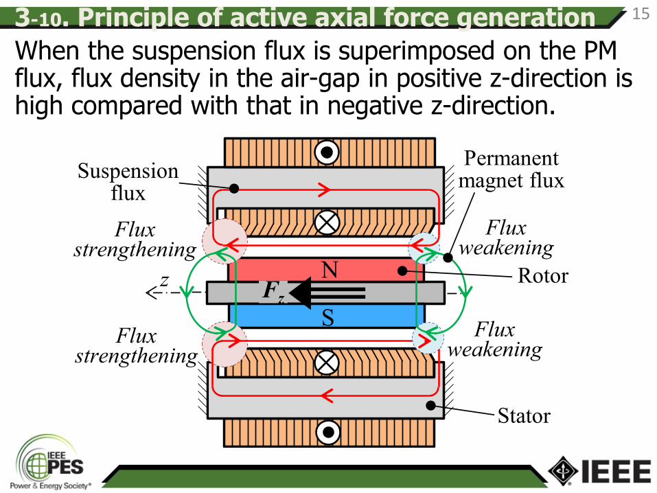
When the suspension flux is superimposed on the PM flux, flux density in the air-gap in positive z-direction is high compared with that in negative z-direction.
3-10. Principle of active axial force generation 15
Stator core
Windingy
x
d-axis
q-axisCurrent
directions
it
UU
V
VW
W
V-shaped winding structure
izit
Stator core
Winding
izit
fz
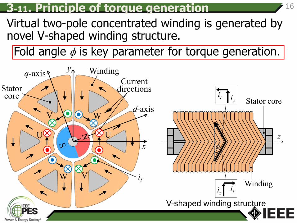
Virtual two-pole concentrated winding is generated by novel V-shaped winding structure.
Fold angle f is key parameter for torque generation.
3-11. Principle of torque generation 16
Rotor PMRPMB RPMB
Unit : cm
Displacement sensor
Windings
Housing
4-1. Test machine 17
z
20°
RPMB RPMBTwo-pole
PM
PM for detecting angular position
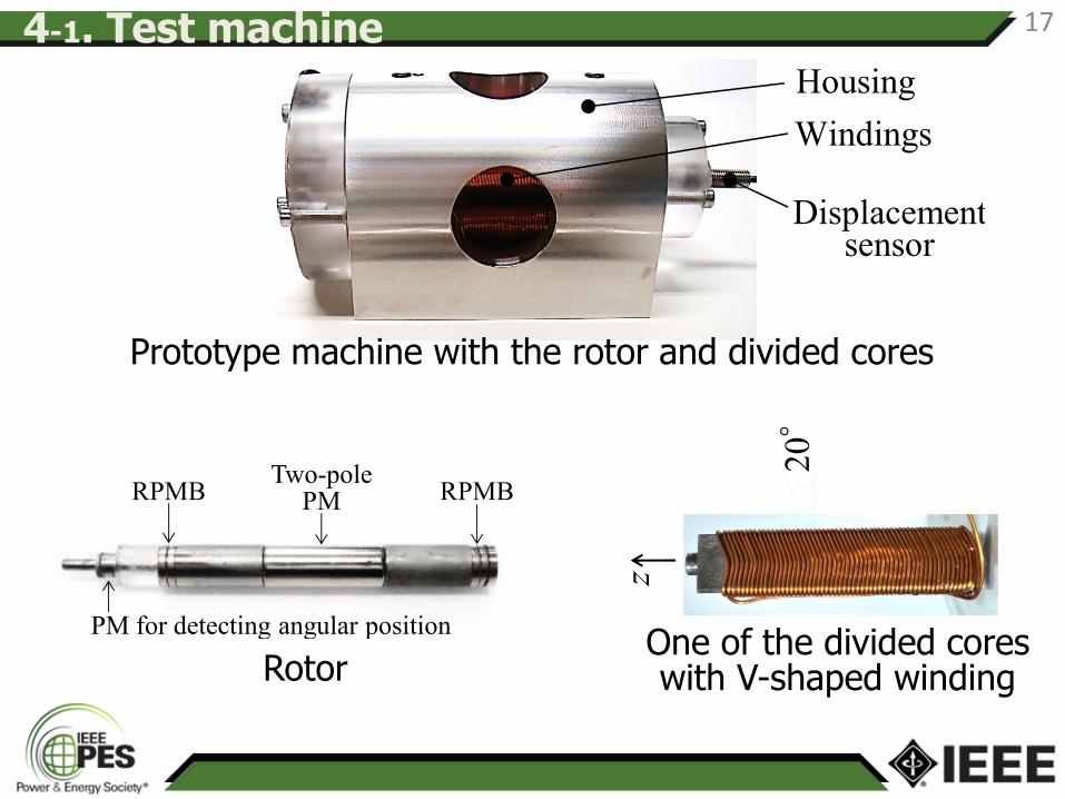
Prototype machine with the rotor and divided cores
Rotor One of the divided cores with V-shaped winding
-0.3
-0.2
-0.1
0.0
0.1
0.2
0.3
0.00 0.02 0.04 0.06 0.08 0.10
Axia
l dis
pla
cem
ent,
z
(mm
)
Time (s)
-4
-2
0
2
4
0.00 0.02 0.04 0.06 0.08 0.10Curr
ent,
id
and i
q(A
)
Time (s)
Axia
l d
isp
lace
men
t,
z (m
m)
-0.2
0.2
0.1
0.0
-0.1
0.00 0.02
0.3
-2
-4
0
2
4-0.3
Cu
rren
t,
i d, i q
(A)
0.04 0.06 0.08 0.10Time (s)
id
iq
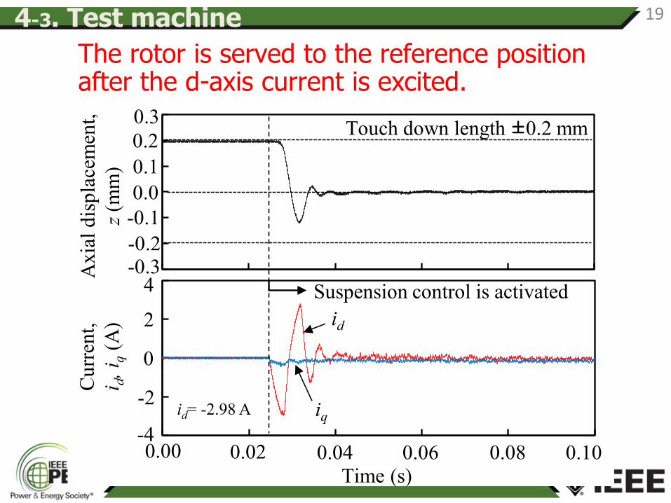
Suspension control is activated
Touch down length ±0.2 mm
id= -2.98 A
The rotor is served to the reference position after the d-axis current is excited.
4-3. Test machine 19
-3
0
3
0.0 1.0 2.0 3.0
-0.2
0.0
0.2
0.0 1.0 2.0 3.0
0
2000
4000
0.0 1.0 2.0 3.00 1 2 30
0
0.0
2
4
3-0.2
0.2
w(1
03
r/m
in)
i d(A
)z
(mm
)
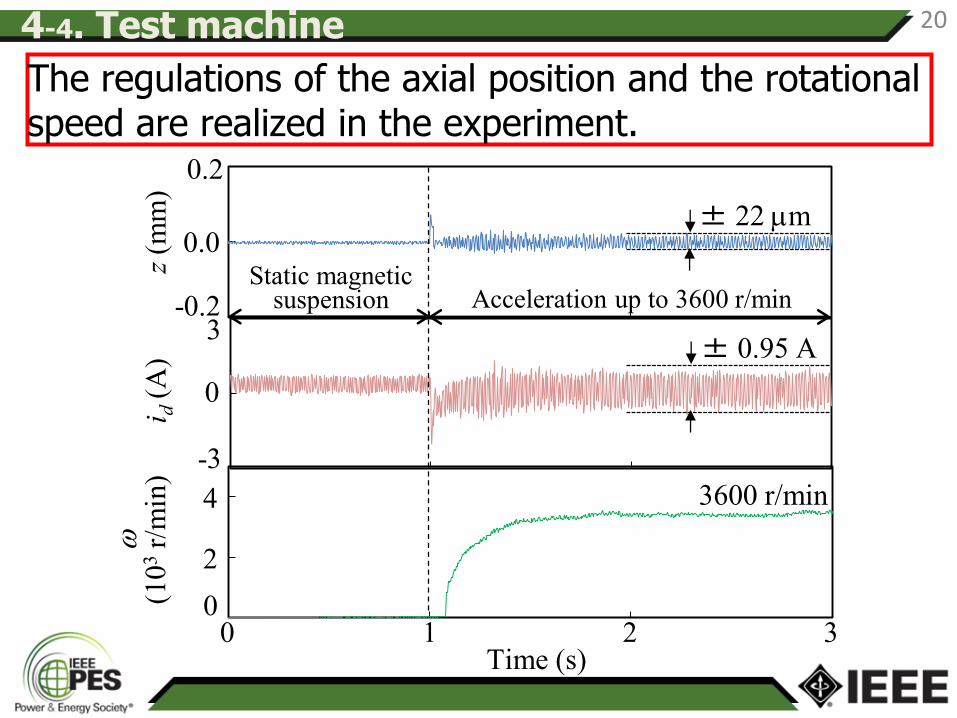
3600 r/min
± 0.95 A
± 22 mm
Time (s)
-3
Static magnetic suspension Acceleration up to 3600 r/min
The regulations of the axial position and the rotational speed are realized in the experiment.
4-4. Test machine 20
A novel single-drive bearingless motor with wide magnetic gap and high passive stiffness is proposed.
Design process of the proposed single-drive bearingless motor is shown.
In the experiments, stable magnetic suspension and speed regulations are confirmed.
5. Conclusion 21