Embed Size (px)
Citation preview

UNIVERSITY OF COLORADO AT COLORADO SPRINGS
Novel Solar Tracking Charge
Device
Course: ECE 4890 Senior Seminar
Project Members: Brian Lessard
Kirk Stetzel
Project Sponsor: Dr. Gregory Plett
Faculty Advisor: Dr. Gregory Plett

Novel Solar Tracking Charge Device v1.0 (Lessard/Stetzel) 1
Table of Contents
Overview ....................................................................................................................................................... 2
Statement of Problem .................................................................................................................................... 2
Operational Description ................................................................................................................................ 3
1. Global Positioning System Data Acquisition ..................................................................................... 4
2. Optimal Angle Calculation Design ..................................................................................................... 5
3. Electro-Mechanical Device Integration and Control ......................................................................... 6
4. Optimal Position Verification ............................................................................................................ 6
5. On-Board Power Supply Control System .......................................................................................... 7
6. Mechanical Platform Design ............................................................................................................. 7
Requirements and Specifications .................................................................................................................. 8
Requirements ............................................................................................................................................ 8
Specifications ............................................................................................................................................ 8
Design Deliverables ...................................................................................................................................... 8
Preliminary System Test Plan ....................................................................................................................... 9
1. GPS Implementation Test Plan ......................................................................................................... 9
2. Optimal Angle Calculation Test Plan ................................................................................................. 9
3. Electro-Mechanical Integration Test Plan ......................................................................................... 9
4. Feedback Sensor Test Plan ................................................................................................................ 9
5. On-Board Battery Control System Test Plan ..................................................................................... 9
6. Mechanical Platform Test Plan ......................................................................................................... 9
7. Complete System Test Plan ............................................................................................................. 10
Reference List ............................................................................................................................................. 11
Revision History .......................................................................................................................................... 11

Novel Solar Tracking Charge Device v1.0 (Lessard/Stetzel) 2
Overview
The main focus of this project is to develop a sun tracking system and physical mount for a flat panel
photovoltaic collector, commonly known as a solar panel. The solar panel will be used to charge a
storage battery as well as provide the necessary power for the sun tracking components. The total
system will be completely autonomous and could be put into service on any hard surface on earth.
Solar power is made by collecting the sun’s energy rays and converting them to electrical current. This
conversion is done by photovoltaic crystals found in today’s solar panels [1, 2]. Modern solar panels
have efficiency ranges from 15 to 20%, with some advanced silicon designs approaching 40% efficiency.
Since the efficiency ratings are well below 50%, it is extremely important to have the solar panel
perform at its maximum output during times of sunlight collection. The two main ways to facilitate this
maximum output are to enhance the sun’s visible light collection process with the addition of solar
concentrators or to keep the solar panel at the optimum elevation angle and exactly perpendicular to
the sun during collection times [3]. The latter approach is the main emphasis of this design project.
Statement of Problem
Most solar panels are placed on fixed mounts that face the southern sky, usually set to an elevation
angle that is given by the pitch of a roof or one based on an average optimum angle for the geographical
location. This common method reduces the amount of sunlight energy conversion and increases the
number of solar panels needed to fulfill the power requirements.
Placing a solar panel on a mount that will track the sun with high accuracy, as well as maintaining the
optimum angle of elevation throughout the calendar year will provide the maximum electrical output of
the panel [4]. On a small scale, this will allow for a smaller panel to be used, which will reduce the
equipment costs to charge the storage battery. On a large scale, namely utility replacement grid-tied
systems, this system will reduce the number of panels needed. This decrease in required devices will
reduce costs as well as square footage needed to mount the panels.
The common type of solar panel sun tracking system uses photo-resistive sensors as the main elements
to keep the panel aligned with the sun [5, 6]. This type of tracking system is susceptible to changes in
light intensity due to environmental factors. These factors include: clouds, trees, shadows caused by
fixed objects, snow and dirt collecting on the sensors, as well as insects crawling on them. The changes
in light cause the tracker to reposition the panel when not necessary or most commonly position the
panel to an incorrect azimuth setting. This will reduce the output of the panel and defray the added
costs of a sun tracking mount versus a fixed mount.
This project will develop a sun tracking system that will offer very high accuracy while eliminating the
negative effects seen by the photo-resistive sensor designs.
Novel Solar Tracking Charge Device v1.0 (Lessard/Stetzel) 3
Operational Description
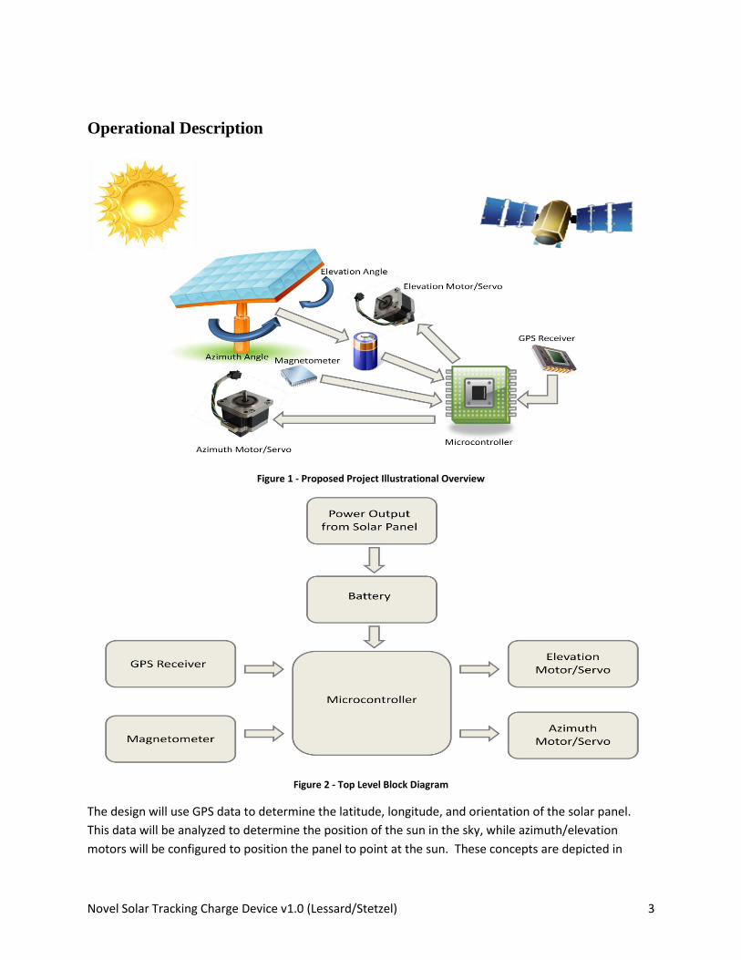
Figure 1 - Proposed Project Illustrational Overview
Figure 2 - Top Level Block Diagram
The design will use GPS data to determine the latitude, longitude, and orientation of the solar panel.
This data will be analyzed to determine the position of the sun in the sky, while azimuth/elevation
motors will be configured to position the panel to point at the sun. These concepts are depicted in

Novel Solar Tracking Charge Device v1.0 (Lessard/Stetzel) 4
Figures 1 and 2. Figure 1 illustrates the components involved in the complete project. It can be seen
that the microcontroller is the central control component, as it receives input from the GPS receiver and
magnetometer sensor. The microcontroller analyzes the input data to output information to the
electro-mechanical devices, which in turn move the solar panel. Figure 2 shows a block diagram
representing the data flow of the design.
This design can be broken into 6 sub-systems. The electrical systems will be monitored and controlled
by a microcontroller. These sub-systems will be designed independently and then integrated to create
the final project.
1. Global Positioning System Data Acquisition
Figure 3 - GPS Data Acquisition Subsystem
The proposed design will incorporate a microcontroller based system that will receive Global Positioning
System (GPS) data to obtain current geographical location, as seen in Figure 3. The received data will
include other factors that will aid in obtaining the optimal position of the solar panel. The critical data
obtained from the GPS receiver will be the latitude, longitude, date and time.

Novel Solar Tracking Charge Device v1.0 (Lessard/Stetzel) 5
2. Optimal Angle Calculation Design
Figure 4 - Optimal Angle Calculation Block Diagram
There are two angles of operation that need to be analyzed and calculated to achieve optimal
performance of the solar panel. The first is the elevation angle, which is the angle of the solar panel
relative to horizontal. There are various ways of determining the optimal elevation angle of the solar
panel. The first is to design a look up table with pre-calculated values depending on the latitude,
longitude, and date. This table could be implemented in a non-volatile memory device, and accessed by
the microcontroller to determine the correct elevation angle.
Another approach would be to develop a microprocessor based mathematical algorithm that will
instantaneously calculate the optimal elevation angle based on the data received from the GPS receiver.
Figure 4 depicts a generic outline of the input data, and the microcontroller determining the optimal
angles. All possible options will be considered for determining optimal angles, and a decision will be
made later to determine the most effective way of handling this angle derivation.
The second angle to consider is the azimuth angle, which is the angle of the solar panel relative to
vertical. This determines how the solar panel will sweep horizontally throughout the day to remain
totally perpendicular to the sun. Deriving this angle will be likely be determined by finding an initial
reference angle as the sun is rising, and incrementally sweeping the solar panel throughout the day.
Again, there are numerous ways to handle determining the optimal azimuth angle, and all options will
be considered before deciding on a final process.

Novel Solar Tracking Charge Device v1.0 (Lessard/Stetzel) 6
3. Electro-Mechanical Device Integration and Control
Figure 5 - Electro-Mechanical Integration Block Diagram
Figure 5 is a continuation of Figure 4, depicting the addition of the implementation of some type of
motor or servo control algorithm internal to the microcontroller.
The desired elevation and azimuth angles will be analyzed by the microcontroller, which will control the
aforementioned electro-mechanical devices, such as stepper motors or servos. These devices will be
attached to the physical mounting structure of the solar panel, and will mechanically move the solar
panel to the desired position.
4. Optimal Position Verification
Figure 6 - Position Verification Block Diagram
The position of the solar panel must be verified in some way to determine that the design is working
properly. Therefore, a sensor such as a magnetometer will be integrated into the design to compare the
actual position of the panel to the desired position, as shown in Figure 6. This will not only act as

Novel Solar Tracking Charge Device v1.0 (Lessard/Stetzel) 7
feedback to verify the accuracy, but will allow the actual angle to be fine-tuned to obtain maximum
efficiency and performance.
5. On-Board Power Supply Control System
Figure 7 - Power Supply Management
The project will be a stand-alone design, with the power supply being an on-board rechargeable battery,
which will eliminate any need for external power. The solar panel will charge the supply battery through
a battery control module, as seen in Figure 7. The on-board battery will only consume a minimal
amount of the power produced. The result will be a fully functional solar panel, producing maximum
efficiency while secondarily powering its own controlling systems.
6. Mechanical Platform Design
A mechanical platform must be designed that will support the project design. The platform must
include a mounting system that will provide the support for the solar panel. The mount must
incorporate rotational aspects, since it will have to pivot on two axes. The electro-mechanical devices
must be incorporated onto the platform, with physical components that will attach the solar panel
mount to the electro-mechanical devices. The microcontroller, GPS receiver, data table memory device,
breadboard/circuit board, and feedback sensors must also be housed on this platform.
To summarize, there are numerous independent design aspects involved in the overall project. First, the
solar panel must provide minimal power to maintain the on-board power supply. Second, the
integration of a GPS receiver must be integrated to obtain data regarding the geographical location of
the solar panel. Next, this information must reference a data table that will produce optimal elevation
and azimuth angles corresponding to the location. Following the table referencing, electro-mechanical

Novel Solar Tracking Charge Device v1.0 (Lessard/Stetzel) 8
devices must physically move the solar panel to the desired position. The actual position of the solar
panel must be compared to the desired position using magnetometer sensors, which will verify the
accuracy of the design. An on-board battery must be charged by the solar panel to provide external
power independence, and finally the physical platform and mounting devices must be constructed to
contain the entire design.
Requirements and Specifications
Requirements
The requirements for this project are as follows:
1. Shall track the sun throughout the entire daylight period for every calendar day
2. Shall employ a flat panel photovoltaic collector to power a commercially available charge
controller and rechargeable storage battery
3. Solution must be microcontroller based running compact algorithms
4. Solution must power all necessary system electronics from photovoltaic collector and storage
battery
5. The final design must position the panel based on calculated position of the sun, making the
system impervious to changes in ambient light or other shading obstructions
6. Must have “accelerated day” demo mode
Specifications
The specifications for this project are as follows:
1. Shall maintain < 5° absolute error in azimuth angle with the sun throughout the day
2. Shall maintain < 5° absolute error in elevation angle based on geographical location
3. Must have sufficient battery storage to run system for a minimum of 36 hours without sunlight
4. Must have rotational freedom of 180 degrees on the horizontal axis and 90 degrees on the
vertical axis
Design Deliverables
The primary deliverable for this project will be a fully functioning, autonomous sun-tracking solar panel.
As previously stated, when the sun is at the proper elevation angle, and completely perpendicular with
the sun’s rays, it will produce the maximum amount of power possible.
Each sub-system of the project must be designed and verified incrementally. The microcontroller must
properly interface with the GPS receiver to receive the critical information. The optimal elevation and
azimuth angles must be determined, and the alteration of the solar panel’s position must be
implemented and verified. The verification for this includes the implementation of sensors, which will
provide data back to the microcontroller to determine what the actual azimuth and elevation angles are.

Novel Solar Tracking Charge Device v1.0 (Lessard/Stetzel) 9
The solar panel must charge an on-board battery which will provide all of the power for the control
system. Lastly, the physical platform must be constructed to support the entire design, with provisions
for axial rotation. The platform shall be lightweight, aesthetically appealing, and weather-resistant.
Preliminary System Test Plan
The test plan for this project will be to test each sub-system individually. Only after each sub-system is
functioning as desired will all of the components become combined to create the overall design. The
preliminary test plans for each sub-system are as follows
1. GPS Implementation Test Plan
Testing the data received from the GPS receiver will be a predominantly visual verification. The
microcontroller will have to initiate communication with the GPS receiver, and then receive and possibly
store the data. This received data will be compared to the actual data (latitude, longitude, time, date,
etc.).
2. Optimal Angle Calculation Test Plan
Simulating numerous different random locations, dates and times will verify that the correct azimuth
and elevation angles are obtained. These angles will be compared to a known good reference table.
This will likely be implemented using simulation software like MATLAB.
3. Electro-Mechanical Integration Test Plan
The test plan for the electro-mechanical devices will be to input numerous different desired elevation
angles and azimuth angles, and tracking the precision of the movement. It is imperative that the
electro-mechanical devices will move the solar panel with fine precision, since a minimum of 1 degree of
accuracy is required.
4. Feedback Sensor Test Plan
The feedback from the sensors will be compared to measured values to determine their accuracy.
5. On-Board Battery Control System Test Plan
This sub-system will likely be implemented using off-the-shelf components, since it is not a primary
design aspect of this project. General voltage and current measurements will be obtained to verify the
performance of the charging system.
6. Mechanical Platform Test Plan
The mechanical platform must be sturdy and allow for rotation on both the horizontal and vertical
planes. Testing this will include verifying the rotational capabilities of the design. It is difficult to specify
a thorough test plan for the physical platform without components mounted to it, so the majority of the
quality of its functionality will be tested during the complete project verification.

Novel Solar Tracking Charge Device v1.0 (Lessard/Stetzel) 10
7. Complete System Test Plan
After all of the individual sub-systems are performing as desired, they will be combined to implement
the final project design. The test plan for this includes verifying that the requirements of the project
have been met. This test plan can therefore be divided into various steps which are stated as follows
Requirement Test Plan Shall track the sun throughout the entire daylight period for every calendar day
Due to time constraints, this cannot be fully verified for every calendar day in a year. Therefore, it will be tested every day that the device is fully functional by performing numerous checks on the solar panel’s location throughout the day.
Shall maintain < 5° absolute error in elevation angle based on geographical location
Measurements will be taken throughout the day to verify the actual azimuth angle of the solar panel. These measurements will be compared to the astronomical information obtained.
Shall be within 5 degrees of the optimal elevation angle based on geographical location
The test plan for this is similar to verifying the azimuth angle, whereas measurements will be taken and compared to expected results.
Must have sufficient battery storage to run system for a minimum of 36 hours without sunlight
The completed system will be run for intervals exceeding 36 hours without charging the battery to verify performance.
Must have rotational freedom of 180 degrees on the horizontal axis and 90 degrees on the vertical axis
The mechanical rotation will be physically verified before and after complete system integration.
The final design must position the panel based on calculated position of the sun, making the system impervious to changes in ambient light or other shading obstructions
The output power of the solar panel will be measured incrementally throughout the day to check its performance. External factors will be simulated to verify that the autonomous tracking features are not affected.

Novel Solar Tracking Charge Device v1.0 (Lessard/Stetzel) 11
Reference List
[1] S. R. Bull, “Renewable Energy Today and Tomorrow,”, IEEE Proc., vol. 89, no. 8, pp. 1216-1226, 2001.
[2] S. Rahman, “Green Power: What is it and Where Can We Find It?,” IEEE Power and Energy Magazine,
vol. 1, no. 1, pp. 30-37, 2003.
[3] Z. G. Piao, J.M. Park, J.H. Kim, G.B. Cho, and H.L. Baek, “A Study on the Tracking Photovoltaic System
by Program Type,” Electrical Machines and Systems, vol. 2, pp. 971-973, 2005.
[4] F. Dobon, A. Lugo, J. Monedero, P. Valera, R. Osuna, L. Acosta, and G. N. Marichal, “First Results of
the Tetra-Track System and Control Electronics,” Photovoltaic Energy Conversion, vol. 2, pp. 2050-2053,
2003.
[5] D. A. Pritchard, “Sun Tracking by Peak Power Positioning for Photovoltaic Concentrator Arrays,” IEEE
Power and Energy Magazine, vol. 1, no. 1, pp. 30-37, 2003.
[6] J. D. Garrison, “A Program for Calculation of Solar Energy Collection by Fixed and Tracking
Collectors,” Sol. Energy, vol. 72, no. 4, pp. 241-255, 2002.
Revision History
Table 1: Revision History Summary
Revision Date Notes
v1.0 4/16/2010 Initial Draft
v1.1 5/6/2010 Updated based on reviews of pre-proposal presentation
![Simulcast Radio Network Design - Home | College of ...mwickert/ece4890/lecture_notes/PericleTalk_fa2008.pdf[1]EIA TSB-88-B, “Wireless Communications Systems — Performance in Noise](https://img.pdfslide.net/doc/110x75/5e75bf257f40ac3ab32c6971/simulcast-radio-network-design-home-college-of-mwickertece4890lecturenotespericletalk.jpg)