Embed Size (px)
Citation preview
C. Newsom November 16, 2001
BTeV Pixel Modeling, Prototyping and
Testing
C. Newsom
University of Iowa
C. Newsom November 16, 2001
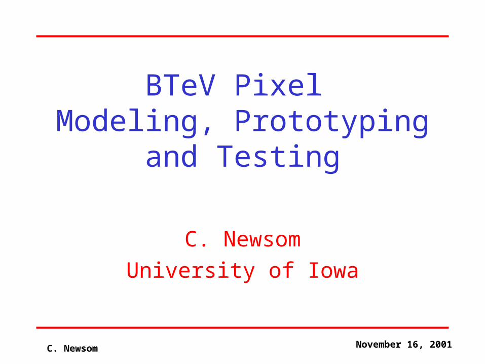
Overview
• Pixel Vessel & Internal support structures
• Vacuum Interface Board
• HDI/Flex Cable tests
• Pixel Support Module prototypes
• Materials testing
• Summary
C. Newsom November 16, 2001
Pixel Vessel and Internal Support Structures
• Rectangular Model-Integrated Carbon Manifold
• Carbon Fiber Half Barrel Structure
C. Newsom November 16, 2001
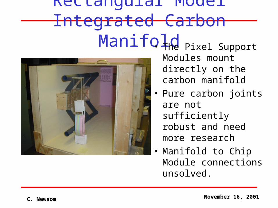
Rectangular ModelIntegrated Carbon Manifold
• The Pixel Support Modules mount directly on the carbon manifold
• Pure carbon joints are not sufficiently robust and need more research
• Manifold to Chip Module connections unsolved.
C. Newsom November 16, 2001
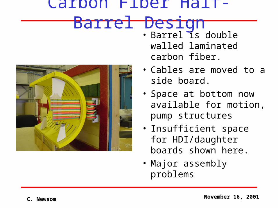
Carbon Fiber Half-Barrel Design• Barrel is double walled
laminated carbon fiber.• Cables are moved to a
side board.• Space at bottom now
available for motion, pump structures
• Insufficient space for HDI/daughter boards shown here.
• Major assembly problems
C. Newsom November 16, 2001
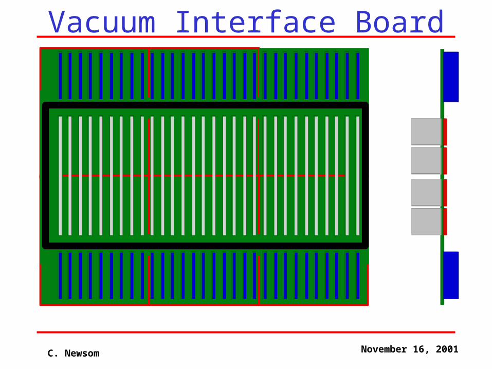
Vacuum Interface Board• Carry ~35,000 signals from inside to
outside the vacuum
• Constructed from 6 separate boards each with its own o-ring.
• Daughter cards have been removed to gain space.
• Ribbon cables pass through the surface and plug into the back side.
• Should we join the 6 boards, build a single board, …?
C. Newsom November 16, 2001
Vacuum Interface Board
C. Newsom November 16, 2001
HDI/Ribbon Cable Flexor
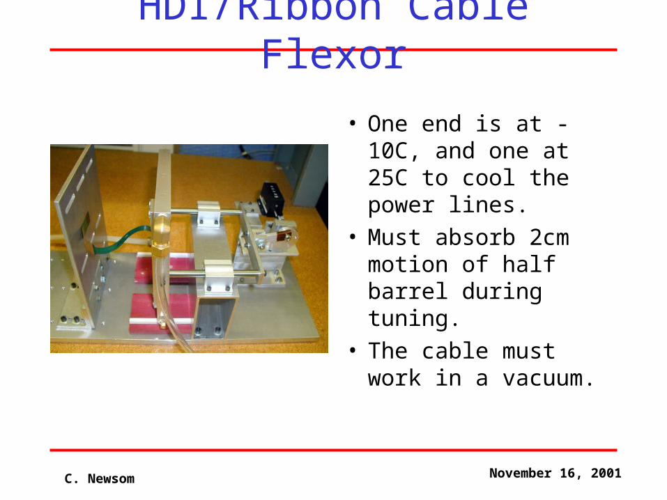
• One end is at -10C, and one at 25C to cool the power lines.
• Must absorb 2cm motion of half barrel during tuning.
• The cable must work in a vacuum.
C. Newsom November 16, 2001
Pixel Support Module Prototypes
• Fuzzy carbon prototypes– Initial Design– Improved Carbon Joints– Current Design
• Beryllium prototypes– Aluminum Modules (serpentine flow)– Aluminum Modules (parallel flow)– Stainless Steel Module (parallel flow)
C. Newsom November 16, 2001
Fuzzy Carbon Prototypes
• Thermal Prototype
• Mechanical Prototype
• Current Status
C. Newsom November 16, 2001
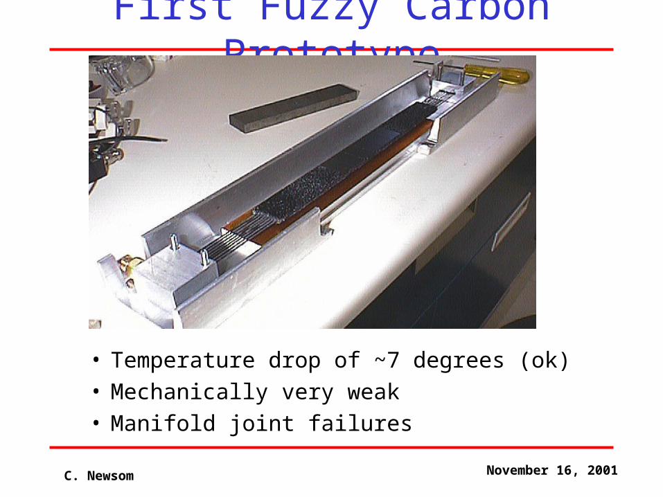
First Fuzzy Carbon Prototype
• Temperature drop of ~7 degrees (ok)• Mechanically very weak• Manifold joint failures
C. Newsom November 16, 2001
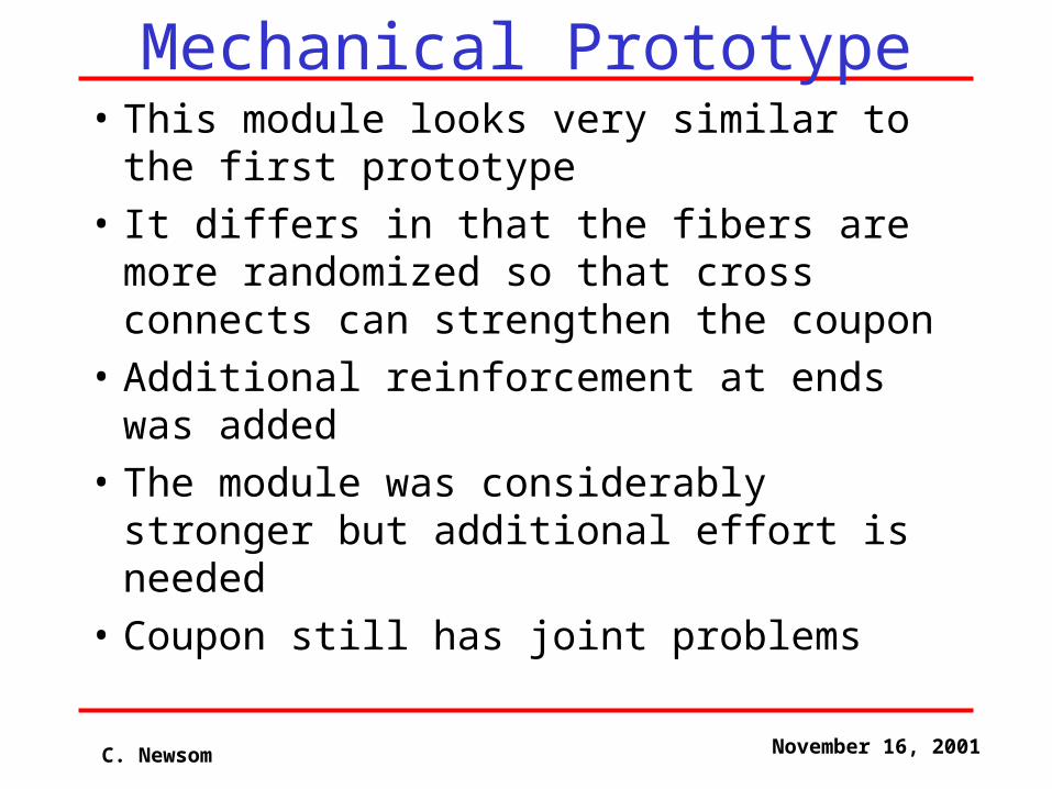
Mechanical Prototype• This module looks very similar to the first
prototype
• It differs in that the fibers are more randomized so that cross connects can strengthen the coupon
• Additional reinforcement at ends was added
• The module was considerably stronger but additional effort is needed
• Coupon still has joint problems
C. Newsom November 16, 2001
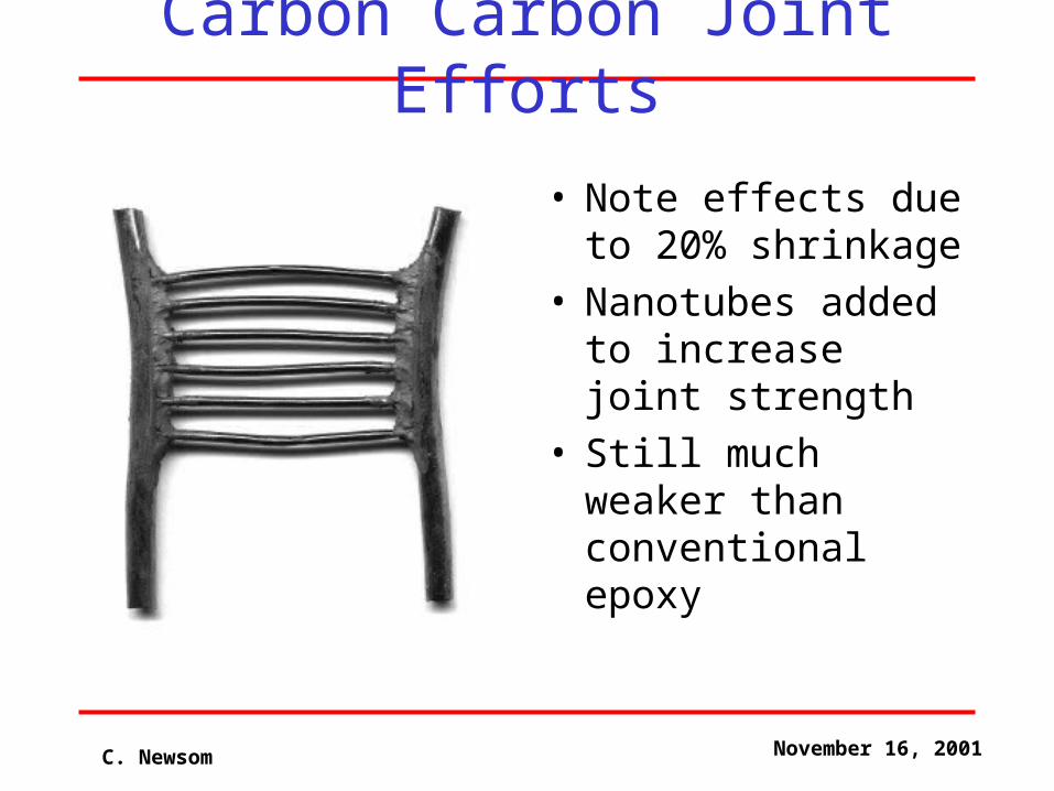
Carbon Carbon Joint Efforts
• Note effects due to 20% shrinkage
• Nanotubes added to increase joint strength
• Still much weaker than conventional epoxy
C. Newsom November 16, 2001
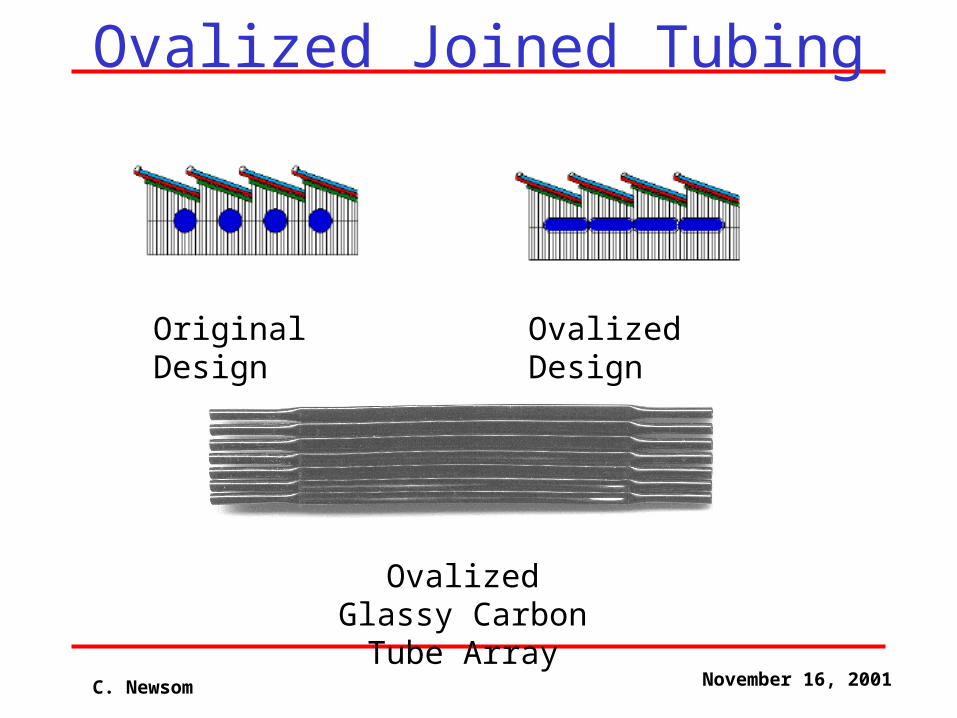
Ovalized Joined Tubing
Original Design Ovalized Design
Ovalized Glassy Carbon Tube Array
C. Newsom November 16, 2001
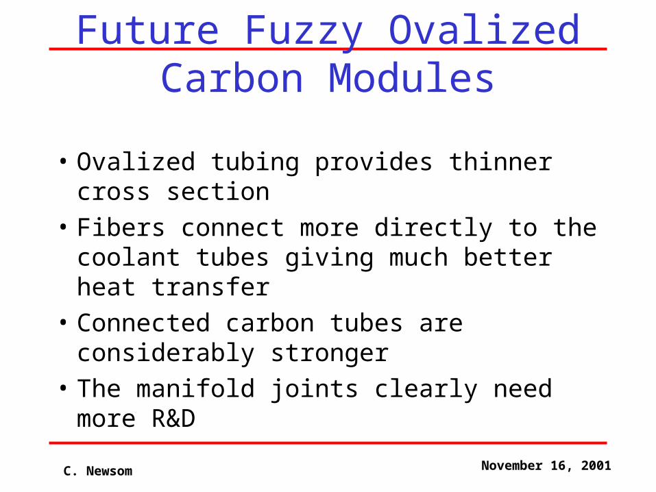
Future Fuzzy Ovalized Carbon Modules
• Ovalized tubing provides thinner cross section
• Fibers connect more directly to the coolant tubes giving much better heat transfer
• Connected carbon tubes are considerably stronger
• The manifold joints clearly need more R&D
C. Newsom November 16, 2001
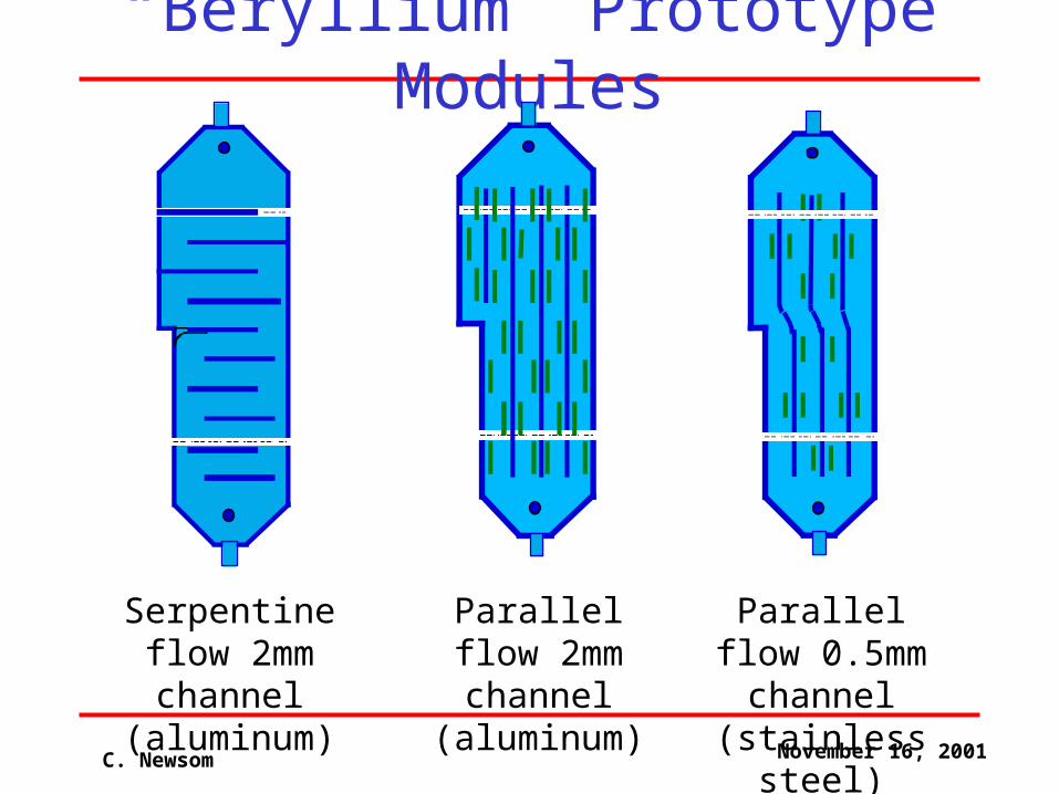
“Beryllium” Prototype Modules
Serpentine flow 2mm channel (aluminum)
Parallel flow 2mm channel (aluminum)
Parallel flow 0.5mm channel (stainless steel)
C. Newsom November 16, 2001
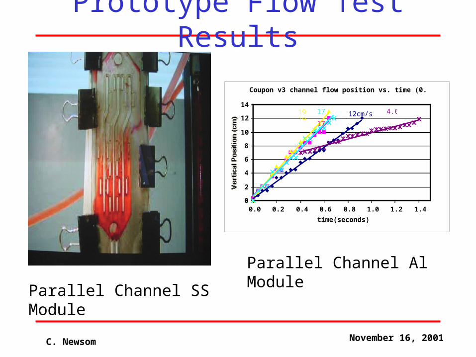
Prototype Flow Test Results
Coupon v3 channel flow position vs. time (0.2 L/min)
0
2
4
6
8
10
12
14
0.0 0.2 0.4 0.6 0.8 1.0 1.2 1.4
time(seconds)
12cm/s
17
1919
17 4.6
Parallel Channel Al Module
Parallel Channel SS Module
C. Newsom November 16, 2001
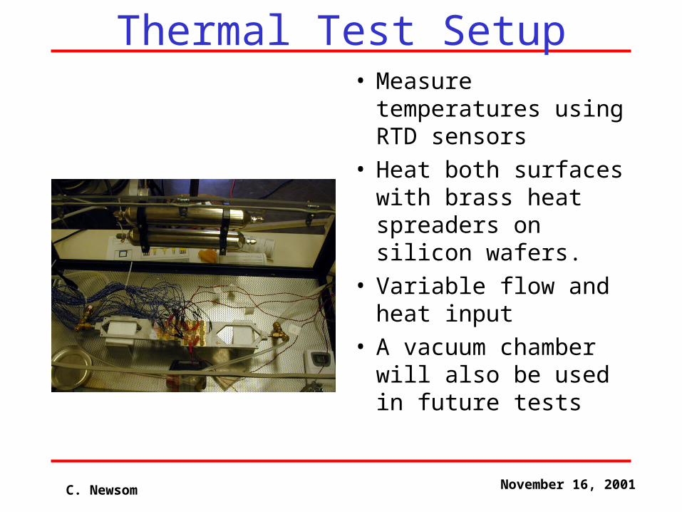
Thermal Test Setup• Measure temperatures
using RTD sensors• Heat both surfaces
with brass heat spreaders on silicon wafers.
• Variable flow and heat input
• A vacuum chamber will also be used in future tests
C. Newsom November 16, 2001
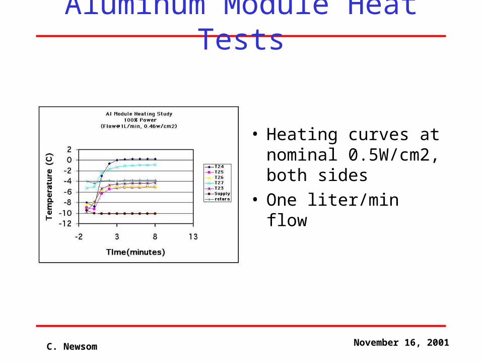
Aluminum Module Heat Tests
• Heating curves at nominal 0.5W/cm2, both sides
• One liter/min flow
C. Newsom November 16, 2001
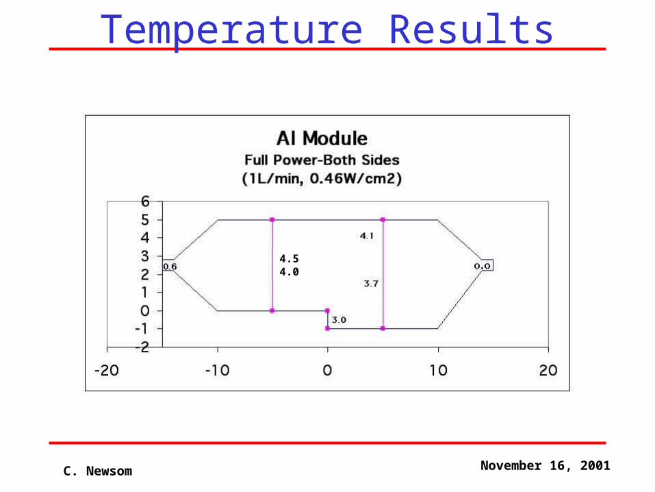
Temperature Results
4.5 4.0
C. Newsom November 16, 2001
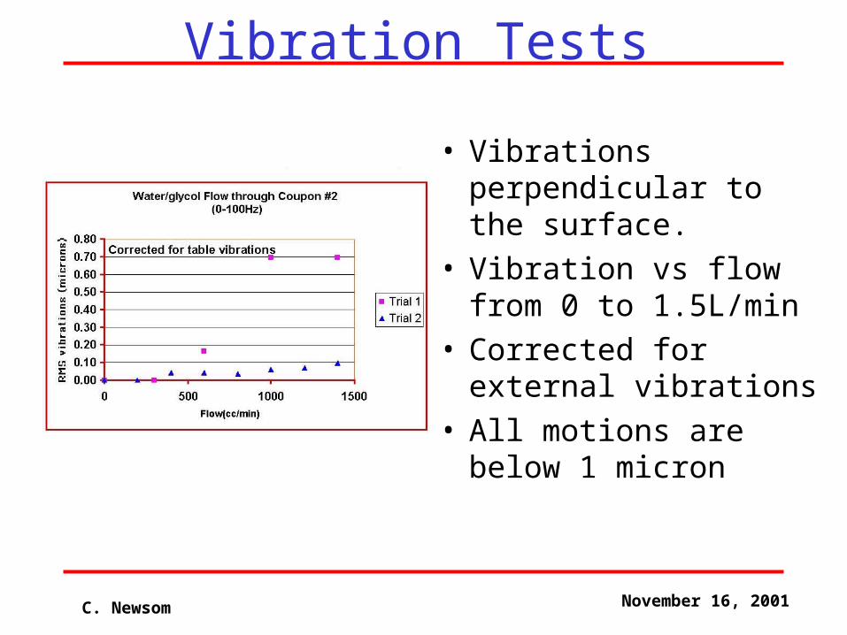
Vibration Tests
• Vibrations perpendicular to the surface.
• Vibration vs flow from 0 to 1.5L/min
• Corrected for external vibrations
• All motions are below 1 micron
C. Newsom November 16, 2001
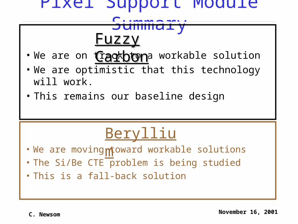
Pixel Support Module Summary
• We are on track to a workable solution
• We are optimistic that this technology will work.
• This remains our baseline design
• We are moving toward workable solutions
• The Si/Be CTE problem is being studied
• This is a fall-back solution
Fuzzy Fuzzy CarbonCarbon
Beryllium
C. Newsom November 16, 2001
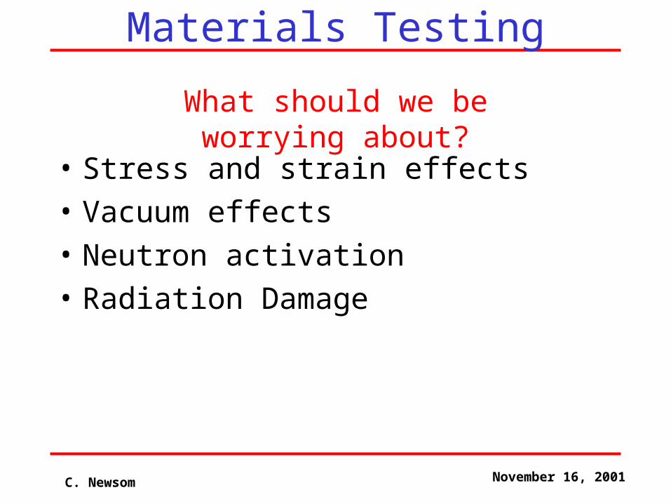
Materials Testing
• Stress and strain effects
• Vacuum effects
• Neutron activation
• Radiation Damage
What should we be worrying about?
C. Newsom November 16, 2001
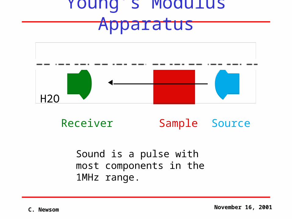
H2O
SourceReceiver Sample
Sound is a pulse with most components in the 1MHz range.
Young’s Modulus Apparatus
C. Newsom November 16, 2001
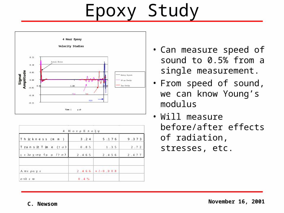
Epoxy Study
• Can measure speed of sound to 0.5% from a single measurement.
• From speed of sound, we can know Young’s modulus
• Will measure before/after effects of radiation, stresses, etc.
4 Hour Epoxy
Velocity Studies
-0.15
-0.10
-0.05
0.00
0.05
0.10
0.15
0.00 5.00 10.00
Time ( μ )s
Water Signal
10 mm Epoxy
3 mm Epoxy
Initial Pulse
2H O
3mm10mm
T h ic k n e s s ( m m ) 3 . 2 4 5 . 1 7 6 9 . 3 7 3
T r a n s i t T im e ( ? s ) 0 . 8 5 1 . 3 5 2 . 7 2
V e l o c i t y ( m m / ? s ) 2 . 4 6 5 2 . 4 5 6 2 . 4 7 7
A v e r a g e 2 . 4 6 6 + / - 0 . 0 0 8
s t d e v 0 . 4 %
4 H o u r E p o x y
C. Newsom November 16, 2001
Conclusions
• We have made significant advances in many areas, solving many problems
• Integration issues are now being studied and solutions incorporated into the baseline design
• Many design parameters are much better understood
• There is a lot of remaining work to be done!