Embed Size (px)
Citation preview

AviationMaintenanceAlerts
AC No. 43-16A
ALERT NO. 256NOVEMBER 1999
Improve Reliability-Interchange ServiceExperience
A L E R T S

CONTENTS
AIRPLANESBEECH ................................................................................................................................................... 1CESSNA ................................................................................................................................................. 3FAIRCHILD .......................................................................................................................................... 7GULFSTREAM .................................................................................................................................... 7MOONEY ............................................................................................................................................... 8NAVION ................................................................................................................................................. 8PIPER ..................................................................................................................................................... 9
HELICOPTERSBELL .....................................................................................................................................................11EUROCOPTER ..................................................................................................................................12SIKORSKY...........................................................................................................................................13
AMATEUR, EXPERIMENTAL, AND SPORT AIRCRAFTAVID .....................................................................................................................................................13KITFOX ................................................................................................................................................14SPACEWALKER ...............................................................................................................................14
POWERPLANTS AND PROPELLERSALLIED SIGNAL...............................................................................................................................15TELEDYNE CONTINENTAL ........................................................................................................15
ACCESSORIES
VERSICON REFUELING HOSE ..................................................................................................16
PARACHUTESSKY-DIVING ACCIDENT ...............................................................................................................17
AIR NOTESADDRESS CHANGES ......................................................................................................................17SUBSCRIPTION FORM ..................................................................................................................18IF YOU WANT TO CONTACT US ................................................................................................18AIRWORTHINESS DIRECTIVES (AD’s) ISSUED IN SEPTEMBER 1999 .......................18AVIATION SERVICE DIFFICULTY REPORTS ......................................................................19

November 1999 FAA AC 43-16A
1
U.S. DEPARTMENT OF TRANSPORTATION
FEDERAL AVIATION ADMINISTRATION
WASHINGTON, DC 20590
AVIATION MAINTENANCE ALERTS
The Aviation Maintenance Alerts provide a common communication channel through which the aviation community caneconomically interchange service experience and thereby cooperate in the improvement of aeronautical product durability,reliability, and safety. This publication is prepared from information submitted by those who operate and maintain civilaeronautical products. The contents include items that have been reported as significant, but which have not been evaluated fullyby the time the material went to press. As additional facts such as cause and corrective action are identified, the data will be publishedin subsequent issues of the Alerts. This procedure gives Alerts’ readers prompt notice of conditions reported via Malfunction orDefect Reports. Your comments and suggestions for improvement are always welcome. Send to: FAA; ATTN: DesigneeStandardization Branch (AFS-640); P.O. Box 25082; Oklahoma City, OK 73125-5029.
AIRPLANES
BEECH
Beech; Model A-36; Bonanza; Defective PitchTrim; ATA 2216
During flight, the pilot experienced an abruptpitch down and elevator trim “run-away”which resulted in a rapid descent. When hedisengaged the autopilot, another abrupt pitchchange occurred.
The technician discovered a defective pitchservo (Allied Signal, Model KS27OC). Thesystem ground tests were satisfactory.However, when the technician engaged theautopilot, the pitch trim “ran away.” After thepitch servo replacement, the systemfunctioned normally.
The submitter suggested that Allied Signalchange the software in the autopilot computerto disallow the possibility of engaging theautopilot (or notifying the pilot) prior toengagement when a pitch failure occurs. Itappears that this problem is related to thetrim sensor in the pitch servo. This could
cause catastrophic results if the autopilot isused during instrument flight rules (IFR)operations.
Part total time-20 hours.
Beech; Model 56-TC; Baron; Flight ControlFailure; ATA 2701
During flight, the pilot experienced severeturbulence, and the flight control columnbroke. The pilot maintained control of theaircraft by using the autopilot and made a safelanding.
An investigation disclosed that the weld brokewhere the shaft was attached to the flange ofthe control column (P/N 96-524011-3) adapterassembly (P/N 96-524029-15). AirworthinessDirective (AD) 71-24-10 addresses this subject,and this aircraft was in compliance withthe AD.
The submitter recommends that the FAAconsider revising the AD to include removingand inspecting the control column adapterand/or replacing the adapter. If defects arefound, the adapter should be replaced with animproved part which is available from themanufacturer.
Part total time-1,981 hours.

FAA AC 43-16A November 1999
2
Beech; Model 95C55; Baron; AutopilotMalfunction; ATA 2210
The pilot stated that while using the autopilotheading mode, the aircraft was placed in anuncommanded 30 degree right turn.
When the right turn began, the pilotattempted to disconnect the autopilot by usingthe button on the control yoke. The disconnectbutton had no effect, and it was necessary toremove electrical power from the autopilot todisconnect the system. The problem wassolved when the technician removed andreplaced the autopilot control head.
Part total time not reported.
Beech; Model 95B55B; Baron; Nose LandingGear Failure; ATA 3230
During landing, the pilot heard a “pop” whenthe nose landing gear wheel touched therunway, and the nose gear collapsed.
After moving the aircraft to a hangar,maintenance technicians discovered the nosegear aft drag brace was broken. The failureoccurred at the point where the nose gearretraction rod is attached to the drag brace.Both of the “tangs” used to attach theretraction rod-end broke and allowed the nosegear to collapse.
The submitter recommended removing,cleaning, paint striping, and nondestructivetesting of this area during each annual and/or100-hour inspection. If cracks are found, Beechsupplies a kit (P/N 35-4012-1S) which replacesthe nose gear aft drag brace.
Part total time-3,500 hours.
Beech; Model 99; Airliner; Entrance DoorMisalignment; ATA 5210
The flightcrew reported that the crewentrance door created excessive wind noiseduring flight.
The technician discovered that the door wasslightly misaligned at the forward edge.Further investigation revealed the hinge(P/N 99-420024-57) on the upper forward sidewas bent. The submitter believes the design ofthe hinge causes this condition when the sealis not properly shimmed and/or the door ishandled roughly.
Part total time not reported.
Beech; Model B100; King Air; Bleed-Air SystemFailure; ATA 7500
During flight, the dual bleed-air failure lightson the master caution panel illuminated. Thepilot made a safe landing and summonedmaintenance personnel.
A maintenance technician discovered twocracked bleed-air lines (P/N 610026) in theright wing. The area surrounding the leakingbleed-air lines was not damaged. Thetechnician replaced the lines, and the systemoperated normally.
The submitter did not offer a cause for thisdefect.
Part total time-76 hours.
Beech; Model 200; King Air; Rudder SkinDamage; ATA 5542
During a scheduled inspection, the techniciandiscovered damage to the left side of therudder skin.
The damage was located adjacent to the trimactuator skin cutout on the leading edge of therudder. A crack approximately .75-inch longappeared near the top of the trim actuatorcutout. The submitter believes this damagewas caused by “wind blast” while the aircraftwas parked on the ramp. The submitterdiscussed the problem with the manufacturerand they decided that a doubler is needed torepair the damaged area. A Designated

November 1999 FAA AC 43-16A
3
Engineering Representative (DER) and themanufacturer agreed the doubler is necessaryfor both airflow and structural integrity.
Possibly the most important step taken by thetechnician is balancing the rudder aftercompletion of the repairs!
Part total time-8,010 hours.
Beech; Model 200; King Air; Entry DoorStructural Crack; ATA 5320
During a phase inspection, the technicianfound a crack on the entry door.
The crack was located on the aft end of thebottom of the door. The channel(P/N 50-430043-019), used to support the doorhinge, was cracked approximately 4 inches inlength, and the crack traveled past the aft setof rivets. The technician replaced the channel.
Part total time-7,601 hours.
Beech; Model 200; King Air; ITT IndicatorInoperative; ATA 7722
The flightcrew reported that the number oneengine inlet turbine temperature (ITT)indicator dropped to zero during a landingapproach.
During an investigation, the techniciandiscovered the ITT indicator (P/N 41-402-1)failed; however, there were no other systemproblems. He removed and replaced theindicator, and all of the functional tests weresatisfactory. The submitter did not offera cause or cure for this discrepancy.
Part total time-411 hours.
Beech; Model 1900D; Airliner; DefectiveRudder Operation; ATA 2215
The flightcrew reported that the aircraftyawed left and right without command. It didnot make a difference whether the yaw
damper was “on” or “off.” The crew selectedthe rudder boost to the “off” position andcontinued the flight.
During an investigation, a team ofmaintenance technicians discovered that theprimary rudder servo (Collins, ModelSVO-65/622-5734-002) was driving the rudderin the wrong direction. After the rudder servowas removed and replaced, the operationaltests were satisfactory. The techniciandisassembled the failed rudder servo anddiscovered that it was improperly assembledduring a previous repair.
Part total time-137 hours.
CESSNA
Cessna; Model 140; Empennage StructuralDamage; ATA 5312
During an annual inspection, the technicianfound the elevator control cable tension low.Several attempts to adjust the cable tensionfailed to produce proper test results.
The technician inspected the elevator cablerouting and discovered there was no pulleymovement in conjunction with movement ofthe cable. Since there are no access panels inthe tail section, it was necessary to removethe entire tail group structure for inspection.The technician found the aft horizontalbulkhead (P/N 0412112) cracked at severallocations, and the elevator cables were“stretched.” (Refer to the followingillustration.)
Part total time-4,006 hours.

FAA AC 43-16A November 1999
4
Cessna; Model 152; Defective Elevator Spar;ATA 5520
The technician removed a damaged elevatorspar assembly (P/N 0432001-21) and ordereda new assembly.
After receiving a new assembly(P/N 0432001-85), the technician conducteda receiving inspection. He discovered the newassembly came with the outboard hingebracket already installed (unlike the originalassembly). The hinge bracket was not installedproperly. If the technician installed the newassembly, the outboard hinge bolt would bemisaligned. He ordered a second assembly andrejected it due to the same defect. He ordereda third assembly, found it serviceable, andinstalled it.
This is yet another case where a thoroughreceiving inspection saved time, money, andprevented an unsafe condition!
Part total time-0 hours.
Cessna; Model 170A; Defective Rudder Pedals;ATA 2720
While removing the rudder pedals to facilitateother maintenance, the technician discoveredseverely elongated attachment holes.
The attachment holes on all four rudderpedals were elongated in the same wearpattern. (Refer to the following illustration.)The technician installed a doubler (.125 inch,6061-T6 aluminum) on both sides of eachattachment hole.
The submitter attributed this defect to“normal wear” following approximately 48years of operation. He recommended that thisarea receive a close inspection, especially onolder aircraft.
Part total time not reported.

November 1999 FAA AC 43-16A
5
Cessna; Model 172R; Skyhawk; FirewallCracks; ATA 5312
After removing the engine cowling for a100-hour inspection, the technician discoveredfirewall cracks adjacent to the cowling shockmounts.
The technician found the firewall(P/N 0553031-1) cracked in the area of the leftand right middle cowling mounts. (Refer to thefollowing illustration.) Cessna Service Bulletin(SB) 98-53-02 deals with this subject.Technicians complied with the inspectionphase after 195 hours of operation with nodefects found. There are three cowling shockmounts on each side of the firewall, the SBstates that cracks may develop at any of theselocations. Also, the SB gives a repair schemefor cracked firewalls. The submitter foundcracked firewalls on three of four like aircraft.The SB applies to specific serial numbers of172R and 172S model aircraft. Refer to the SBfor specific aircraft applicability. Thesubmitter urges all operators to comply withthe SB as soon as possible. He also stated thatthis area deserves close attention duringscheduled inspections.
Part total time-389 hours.
Cessna; Model 182R II; Skylane; DefectiveBattery Box Support; ATA 5320
During an annual inspection, the maintenancetechnician found the battery box supportangles (P/N 0712059-1) were cracked.
The battery box is located in the empennage.If the battery box is uncontained, the weight ofthe battery could result in a seriousout-of-balance condition. Even though thesupports displayed some corrosion, thesubmitter attributed this failure to theinadequately-designed battery box support.He stated this is a very common condition andsuggested the manufacturer construct a morestructurally-substantial design to support thebattery box.
Part total time-1,381 hours.
Cessna; Model 182S; Starter Failure; ATA 8011
During a takeoff roll, the pilot noticed all ofthe radio lights flickering and the voltmeterindicated 21 volts. He aborted the takeoff andconducted an operational test. The test did notduplicate the incident. When the pilotattempted another takeoff, he experienced thesame problem.
When a maintenance technician attempted tostart the engine, the starter (P/N PM2401) wascompletely inoperative. Troubleshootingrevealed electrical power present at thestarter, and the failure was internal. Thesubmitter speculated that the starter solenoidstuck in the engaged position causing thestarter to be driven by the engine. Thissubmitter knows of six similar failures on likeaircraft.
Part total time-87 hours.

FAA AC 43-16A November 1999
6
Cessna; Model A185F; Skywagon; LandingGear Failure; ATA 3213
During a landing rollout, the left main landinggear separated from the aircraft. The aircraftnosed over and came to rest on its back.
An investigation revealed that the gear leg(P/N 0741001-3) had sheared through the twoupper bolt holes used to attach the axle. Thisaircraft was fitted with wheel skis in thewinter and tires in the summer. Most of theflying was from “unimproved” (off-airport)landing strips. Due to these conditions, thesubmitter suspected metal fatigue caused thisdefect. He suggested that similarly-usedaircraft receive an annual x-ray inspection ofthe critical landing gear parts.
Part time since overhaul-2,490 hours.
Cessna; Model U206G; Stationair; AileronHinge Assembly Damage; ATA 5751
During other maintenance, the techniciandiscovered damage to a right wing aileronhinge bracket assembly.
Both the right wing inboard and outboardaileron hinge bracket assemblies(P/N’s 1220053-12 and 1220052-12) displayedcracks on the lower side. The technician alsofound loose and sheared rivets at the pointwhere the brackets attach to the rear wingspar. One cannot see this type of damagewithout removing the false spar. However,defects are evidenced by looseness andmovement of the hinge brackets in anup-and-down direction.
The submitter has experienced this defect onother 206 and 207 model aircraft. He statedthe two bottom rivets in the bracket, which gothrough the lower skin, loosen or shear first;and then the angle riveted to the spar flexesand cracks.
Part total time-8,120 hours.
Cessna; Model 560; Citation; Brake SystemFailure; ATA 3242
During landing, the flightcrew experiencedcomplete failure of the primary brake system.The pilots used the emergency brake systemand the thrust reversers to stop the aircraft.
When the aircraft taxied into the parkingramp, a maintenance technician noticedhydraulic fluid leaking from a drain hole in thenose landing gear area. He inspected theprimary brake system and discovereda ruptured hydraulic system reservoir(P/N 651710022). The failure occurred at theforward inboard welded seam. A crack,adjacent to the welded seam, traveledapproximately 4 inches upward from the lowerforward corner of the reservoir. Thetechnician did not find plumbing obstructionsor other problems that caused this defect. Hesent the reservoir to Cessna for evaluation.
Part total time-2,366 hours.
Cessna; Model 650; Citation; Defective MainLanding Gear Uplock Assembly; ATA 3230
During a scheduled inspection, the techniciandiscovered a loose left main landing gearuplock assembly.
All four of the bolts (P/N AN4-7A) used tosecure the uplock assembly (P/N 6214102-7) tothe aircraft structure were loose. The boltsthread into self-locking nut plates(P/N MS21069L4) and have no other safetydevice. (Refer to the following illustration.)The technician applied “Loctite 271” to thebolt threads, and torqued the bolts to theproper setting. The right main gear uplockassembly was tight; however, the bolts were atless than the specified torque value. Thesubmitter suggested that the manufacturer

November 1999 FAA AC 43-16A
7
use “drilled head” bolts (P/N AN4H-7A) at thislocation. The “drilled head” bolts can be safetywired.
Part total time-1,949 hours.
FAIRCHILD
Fairchild; Models SA226 and SA227; Metro;Landing Gear Anomaly; ATA 3230
The FAA, Aircraft Certification Office,ASW-150, located in Fort Worth, Texas,submitted the following article. (The articleis printed exactly as it was received fromASW-150.)
Two Metros recently experienceduncommanded landing gear retractionsduring ground operations. Both aircraftwere equipped with the same HydraulicPower Pack (P/N 27-81009).
In both cases, the cause was determined tobe an undetected or latent malfunction
within the landing gear control valve whichis a component of the Hydraulic PowerPack. As a result, the manufacturer(Fairchild) issued Service Letters(SL) 226-SL-012, 227-SL-037, andCC7-SL-029, with subsequent revisions, toestablish overhaul criteria for theHydraulic Power Pack and for systemground operating procedures.
The repetitive overhaul proceduresrequired by the Service Letters willeliminate the latent failures that causedthe uncommanded gear retractions. Thesefailures are not necessarily detectable inthe normal landing gear functional checksand could occur at anytime on high timeHydraulic Power Packs unless thepreventive maintenance required by theService Letter is performed. Although thereported malfunctions have thus faroccurred with the affected aircraft ina ground static position, it is possible thatsuch an uncommanded gear retractioncould occur during an approach if electricalpower to the Hydraulic Power Pack isinterrupted.
Part total time not applicable.
GULFSTREAM
Gulfstream; Model G-1159; Electrical SystemDamage; ATA 2434
During an engine operational test on theground, the left generator occasionally trippedoff line.
An investigation revealed that the generatorshunt ground pad (P/N 1159AV20467-13) wasseverely heat damaged. The maintenancerecords indicate the shunt ground pad wasrecently removed during a corrosioninspection. The submitter speculated that thebolt securing the ground pad was not properlytorqued, or the ground pad was not matedflush with the shunt prior to tightening theattachment hardware. These parts are locatedin the tail section aft of the pressure bulkhead.

FAA AC 43-16A November 1999
8
The submitter suggested that all operatorsinspect this area for similar damage at theearliest possible time.
Part total time-5,157 hours.
MOONEY
Mooney; Model M20J; Damaged Pitot Tubing;ATA 3411
This aircraft was involved in a landingaccident which destroyed the aircraft. Thedefect reported here may have been acontributing factor to the accident.
During the accident investigation, the pitotsystem tubing was found crushed. The tubingwas improperly routed between the fuselageframe and the skin on the left side. Thisresulted in restricted flow to the airspeedindicator and lower than actual airspeedindications.
Part total time-397 hours.
Mooney; Model M20K; Exhaust SystemComponent Cracking; ATA 7800
We received two reports concerning exhaustsystem component cracking on two differentMooney M20K aircraft. Both aircraftincorporated Supplemental Type Certificate(STC) SA5691NM. The STC concerns installinga Continental TSIO-520-NB engine.
The first report cites a cracked left lower rearturbocharger mount bracket (P/N 505-03-504).Due to cracking at 179 hours, a technicianpreviously replaced the right frontturbocharger mount bracket. The submittersuggests inspecting this area each timea technician removes the engine cowling.
The second report cites cracking adjacent towelds and where the engine baffling rubbedagainst the tailpipes, headers, and transitionpipes (P/N 305-01-507HS). The submitter found
engine exhaust stains throughout the enginecompartment. He also noted that theunthreaded portion of the bolt shank on theengine lord mount was too long, allowing theengine to vibrate. The exhaust system is “hardmounted,” and requires force to put into place.
Part total time of first aircraft-212 hours. Parttotal time of second aircraft-584 hours.
NAVION
Navion; All Models; Flight Control CableCorrosion; ATA 2710
The submitter discovered severely corrodedaileron cables on several different aircraft. Hestated the damage usually appears justoutboard of the wheel wells. To properlyinspect this area, a technician has todisconnect the cables at the aileron bellcrankand pull them into the wheel well. On oneaircraft, the submitter only found twounsevered cable strands.
Part total time not reported.
Navion; Model A; Landing Gear Uplock Failure;ATA 3230
When the pilot selected the landing gear tothe “down” position for landing, the gear didnot extend. The pilot executed a gear-uplanding.
An investigation revealed a broken clevis pin(P/N AN 393-7). The clevis pin attaches thelanding gear lock release to the hydraulicpowerpack. The clevis pin broke at thecotter-key hole, migrated, and disconnectedthe landing gear lock release cable from thegear handle. The submitter suggestedremoving and inspecting the clevis pin duringeach annual inspection.
Part total time not reported.

November 1999 FAA AC 43-16A
9
PIPER
Piper; Model PA24-180; Comanche; StabilatorCorrosion; ATA 2740
The technician removed both stabilators toreplace the bearings.
The technician found corrosion on thestabilator torque tube (P/N 22655-00). Thetechnician could not see this area until heremoved the stabilators. He discovered thetorque tube did not have any paint or othercorrosion protection present.
The submitter suggested removing thestabilators and inspecting and painting thetorque tube every 1,000 hours of operation.
Part total time-3,763 hours.
Piper; Model PA24-250; Comanche; DefectiveWing Attachment; ATA 5341
During an annual inspection, a techniciandiscovered the right wing aft attachmentfitting was missing rivets.
The wing attachment fitting is located underthe aft baggage compartment floor. The plate(P/N 23662-00) and fitting (P/N 23663-00) were“misaligned.” The technician discovered all ofthe fasteners in these two parts either brokenor missing. This finding prompted aninspection of the left wing attachmentassembly. The left side appeared aligned, andall of the rivets were in place. However, thetechnician could pull out many of the rivetbucktails using only finger pressure.
The submitter speculated that hard landingscaused this damage.
Part total time-3,607 hours.
Piper; Model PA28-160; Cherokee; Loss ofEngine Power; ATA 7600
During flight, the aircraft engine powersuddenly reduced to approximately 1500 RPM.This loss of power resulted in an emergencylanding in water. All of the aircraft occupantsescaped without injury.
Accident investigators found that the rubberin an “Adel” clamp (Piper P/N 63916-02), usedto secure the engine throttle cable, haddeteriorated to the point of allowing theengine throttle cable housing to slide insidethe clamp. This caused a reduction in throttlecable travel and allowed a maximum of1500 RPM. In this case, a cheap part causedendangerment of the aircraft occupants andsubstantial damage to the aircraft!
Part total time-3,574 hours.
Piper; Model PA28-161; Warrior; EngineVibration; ATA 7120
After returning from a flight, the pilotreported engine vibration during enginestarting and shutdown procedures.
An inspection disclosed a loose right lowerengine mount-to-firewall bolt (P/N AN 6-26A).Also, the bolt grip length was too long andallowed the nut to bottom out on the threads.The maintenance records revealed the bolthad not been replaced since the aircraft wasnew.
Part total time-837 hours.

FAA AC 43-16A November 1999
10
Piper; Model PA28-181; Archer; InaccurateAirspeed Indication; ATA 3411
The pilot reported that the airspeed indicationwas not accurate.
An investigation revealed two torn flexiblehoses (P/N’s 63913-122 and -123). The hosesconnect ridged metal lines to the pitot mast inthe left wing. The hose tears appeared at thepoint where they attach to the metal lines.
The submitter reported that avionicspersonnel recently performed maintenance inthis area. He speculated this problem occurredwhen the avionics personnel removed andpulled down the pitot mast.
Part total time-406 hours.
Piper; Model PA31-350; Chieftain; Cockpit FuelLeak; ATA 7332
During flight, the pilot detected a strong fuelodor. He observed fuel dripping from theinstrument panel onto the copilot’s rudderpedals. The pilot made an immediate anduneventful landing.
A technician investigated and found a fuelpressure hose (P/N 80048-04) leaking at thefuel pressure gauge. After removing the hose,the technician found a small split runninglengthwise on the hose.
The submitter stated this hose may be originalequipment and attributed “old age” as thecause of the defective hoses.
Part total time-9,278 hours.
Piper; Model PA31T-500; Cheyenne I;Air-Conditioning System Inoperative; ATA 2100
During a scheduled inspection, the technicianfilled the air-conditioning system due to “lowoutput.”
After servicing the system, the techniciandiscovered a Freon leak on the low pressureside in the right wing’s leading edge. The leakoriginated from a “B” nut fitting on a line(P/N 50489-00). The technician could not stop
the leak by tightening the “B” nut. (Most of usare guilty of trying to tighten a line or fittingto stop a leak with pressure on the system;however, it is not a safe practice!) Thetechnician evacuated the system and removedthe line for closer inspection. He discoveredsevere corrosion on the flare at the leakingend of the line. The corrosion penetratedthrough the flare wall thickness.
Since the location of the hose is at the lowestpoint in the system, the submitter speculatedthat moisture accumulation caused the severecorrosion.
Part total time-5,189 hours.
Piper; Model PA31T-620; Cheyenne; HorizontalStabilizer Crack; ATA 5511
During a scheduled inspection, the techniciandiscovered a crack on the horizontal stabilizer.
The crack appeared on the left horizontalstabilizer (P/N 46538-024) rear spar web.(Refer to the following illustration.) The cracktraveled from an upper rivet, used to attachthe spar web, to a bonding strap hole. Thesubmitter did not offer a cause for this defect.
Part total time-4,595 hours.

November 1999 FAA AC 43-16A
11
Piper; Model PA32R-301T; Turbo Saratoga;Defective Vertical Stabilizer Attachment;ATA 5530
During an annual inspection, the techniciannoticed movement when he exerted handpressure against the top of the verticalstabilizer. At the same time, he heard a noisewhich seemed to come from the lowerattachment point.
The technician removed the four rear sparattachment bolts (P/N AN-4-6A). Hediscovered wear marks made by movement ofthe attachment point surfaces. (Refer to thefollowing illustration.) The torque on theattachment bolts was less than the required100-inch pounds. The submitter stated thiswas the third similar defect he has found onlike aircraft within the past year. Herecommended that the manufacturer replacethe stabilizer attachment bolts with,ream-to-fit, AN-174-series close tolerancebolts.
Part total time-2,278 hours.
Piper; Model PA34-200; Seneca; RudderControl Failure; ATA 5540
During ground operation, the rudder went tofull left deflection and could not be returned tothe neutral position.
An investigation revealed that the rudder armassembly (P/N 95386-00) failed at the pointwhere it is welded to the cross-bar assembly.This aircraft is used for flight instruction andused to demonstrate single-engine operation.Single-engine operation requires full ruddertravel to maintain control of the aircraft. Thesubmitter suggested that all operators of likeor similarly-constructed aircraft immediatelyinspect for cracks and damage in this area.
Part total time-5,200 hours.
HELICOPTERS
BELL
Bell; Models 214-B, 214-B1, and 214ST;Improperly-Manufactured Main Rotor StrapPins; ATA 6200
The FAA, Rotorcraft Certification office,ASW-170, located in Fort Worth, Texas,submitted the following article. (The articleis printed exactly as it was received fromASW-170.)
Bell Helicopter has identified a number ofmain rotor strap pins (P/N 214-010-117-001)which may not have been manufacturedcorrectly.
Bell issued Alert Service Bulletins(ASB’s) 214-99-61 and 214ST-99-81, bothdated July 5, 1999, which deal with thissubject. The text of these ASB’s containsinstructions for removal of certain pinserial numbers from stock and service atthe next scheduled tension-torsion

FAA AC 43-16A November 1999
12
strap/pin change or within a specified timeinterval. Refer to the applicable ASB forspecific instructions.
Part total time-not applicable.
Bell; Model 407; Bearing Failure; ATA 6510
While flying straight and level at 3,700 feet,the pilot experienced two sharp vibrations.The vibrations lasted approximately 2 secondsand were 1 second apart. The pilot made animmediate and successful precautionarylanding.
An investigation revealed that some of thebearing balls were missing from the forwardend of number 2 tailrotor drive shaft bearingassembly. The technician determined that anuncontained failure of the forward bearing(P/N 407-040-303-105) caused the vibrations.
The submitter did not offer a cause or meansof preventing this type of defect.
Part total time-302 hours. Part time sinceoverhaul-79 hours.
Bell; Model 407; Main Rotor Trunnion BearingFailure; ATA 6700
During a scheduled inspection, the techniciandiscovered premature failure of a main rotortrunnion bearing.
The main rotor trunnion bearing(P/N 406-310-405-101) life limit is 5,000 hours.Previously, the technician found three bearingfailures, and each of these bearings has lessthan 1,000 hours in service. He rejected thesebearings because of axial play beyond.005 inch. Since this part is critical to flightsafety, the submitter notified themanufacturer of the problem. Bellacknowledged this defect and is presentlyworking on a solution.
Part total time-238 hours.
EUROCOPTER
Eurocopter; Model BK117B1; Chip PlugInstallation; ATA 7261
Following a 25-hour inspection, the technicianstarted the engine and discovered a largeengine oil leak.
An inspection revealed the leak came from thechip plug. The chip plug dislodged from thesocket and allowed a copious quantity ofengine oil to escape. Apparently, the valve inthe chip plug housing was not seated properlyand did not fully engage the locking device.
The submitter recommended exerting a firm“pull down” on the chip plug after turning thechip plug to the locked position to ensure it isfully locked. This advice applies to any otheraircraft using this type of engine chip detectorplug.
Part total time not reported.
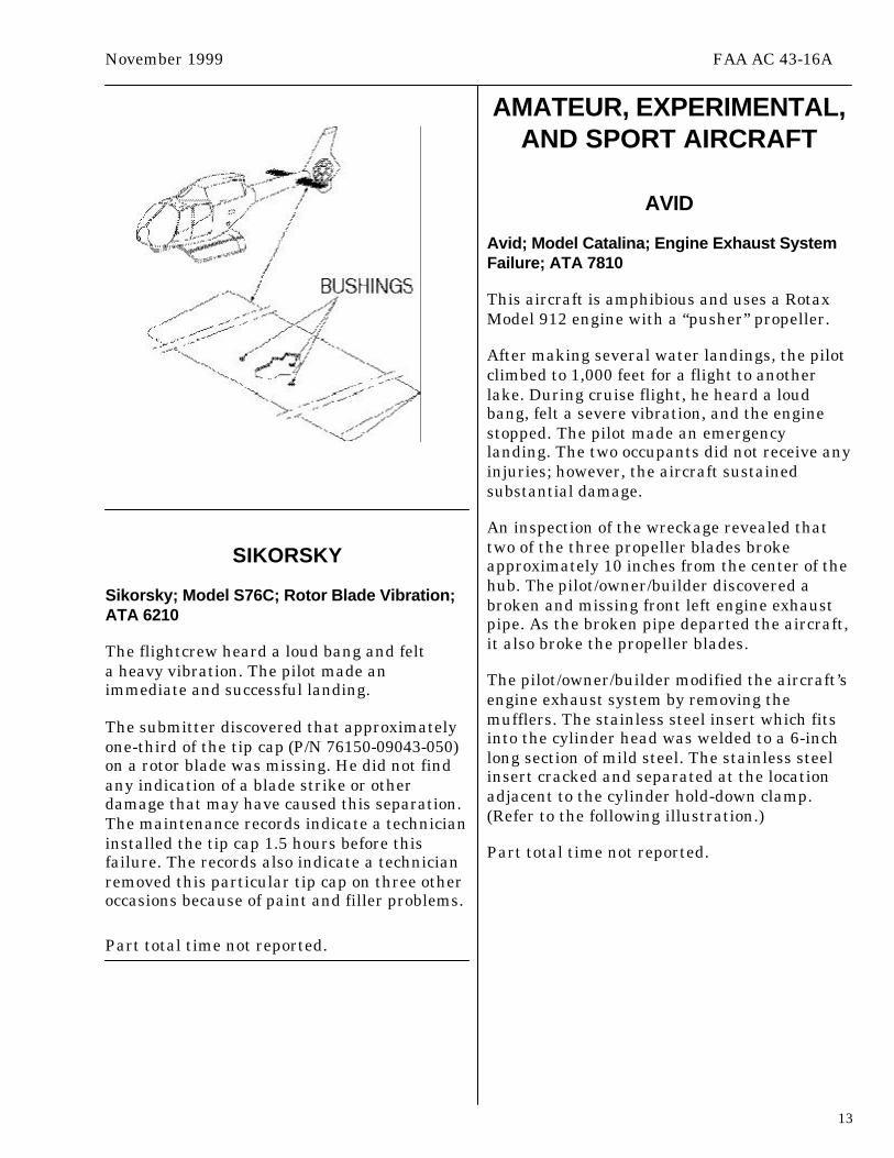
Eurocopter; Model EC 120B; HorizontalStabilizer Bushing Loose; ATA 5510
During a daily inspection, the techniciandiscovered that the left horizontal stabilizersupport bushing was pulled out of thestabilizer. The bushings bond into thecomposite stabilizer structure. (Refer to thefollowing illustration.) No other damageappeared on the stabilizer mount brackets orthe tail boom. As a precaution, the submitterconducted a balance inspection on the“Fenestron” at 100 percent flat pitch on theground. The inspection revealed anout-of-balance condition.
The submitter speculated that inadequateadhesion between the bushing inserts and thecomposite material caused this problem.
Part total time-40 hours.
November 1999 FAA AC 43-16A
13
SIKORSKY
Sikorsky; Model S76C; Rotor Blade Vibration;ATA 6210
The flightcrew heard a loud bang and felta heavy vibration. The pilot made animmediate and successful landing.
The submitter discovered that approximatelyone-third of the tip cap (P/N 76150-09043-050)on a rotor blade was missing. He did not findany indication of a blade strike or otherdamage that may have caused this separation.The maintenance records indicate a technicianinstalled the tip cap 1.5 hours before thisfailure. The records also indicate a technicianremoved this particular tip cap on three otheroccasions because of paint and filler problems.
Part total time not reported.
AMATEUR, EXPERIMENTAL,AND SPORT AIRCRAFT
AVID
Avid; Model Catalina; Engine Exhaust SystemFailure; ATA 7810
This aircraft is amphibious and uses a RotaxModel 912 engine with a “pusher” propeller.
After making several water landings, the pilotclimbed to 1,000 feet for a flight to anotherlake. During cruise flight, he heard a loudbang, felt a severe vibration, and the enginestopped. The pilot made an emergencylanding. The two occupants did not receive anyinjuries; however, the aircraft sustainedsubstantial damage.
An inspection of the wreckage revealed thattwo of the three propeller blades brokeapproximately 10 inches from the center of thehub. The pilot/owner/builder discovered abroken and missing front left engine exhaustpipe. As the broken pipe departed the aircraft,it also broke the propeller blades.
The pilot/owner/builder modified the aircraft’sengine exhaust system by removing themufflers. The stainless steel insert which fitsinto the cylinder head was welded to a 6-inchlong section of mild steel. The stainless steelinsert cracked and separated at the locationadjacent to the cylinder hold-down clamp.(Refer to the following illustration.)
Part total time not reported.

FAA AC 43-16A November 1999
14
KITFOX
Kitfox; Model II; Engine Failure; ATA 8530
This aircraft had a Subaru Model EA-81 engineinstalled.
During flight, the pilot experienced a loss ofengine power and could not restore the power.He made a successful off-airport emergencylanding.
The submitter discovered a broken snapring.The snapring secures the number 1 cylinderexhaust rocker arm. When the snapring broke,the rocker arm separated from the rockershaft. The submitter did not give a cause forthe snapring failure.
Part total time not reported.
SPACEWALKER
Spacewalker; Model II; Structural Failure;ATA 5700
The FAA Flight Standards District Office(FSDO) in Houston, Texas, submitted thefollowing article. (This article is printedexactly as it was received from the FSDO.)
This accident investigation has not yetbeen completed, and the information givenin this article may or may not becompatible and factual when the finalreport is released.
Ground observers reported that thisaircraft was flying straight and level atapproximately 1,200 feet when it, slightlyand erratically, rolled from left to right anda loud snap or popping noise was heard.The aircraft’s left wing separated, and theaircraft struck the ground in an almostvertical attitude. This resulted in twofatalities and destruction of the aircraft.
The aircraft designer stated that the leftwing rear spar broke initially whichimposed a torsional twisting load on theremainder of the wing structure. Theabnormal torsional load bent the wing mainspar attachment point to fuselage carrythrough structure. This resulted in suddenand catastrophic wing failure. The woodused for the front and rear wing sparsappeared to fracture almost vertically withno ripping or tearing of the wood grain orstructure.
The history of this aircraft brought to lightsome interesting information. The aircraftwas originally certificated in 1991 and wasbuilt from a kit by an individual who was aprofessional cabinet maker. The aircrafthad been sold four times after it wasoriginally built. The builders recordsindicated that the builder substitutedbasswood for the rear wing spar duringconstruction. The aircraft designer calls forthe use of “spruce” for construction of thewing spars. Also, the kit manufacturerdiscovered several anomalies that mayhave occurred during the originalconstruction. The welded tubing area,where the rear spar carries through thefuselage structure, is designed oversizedvertically. This allows the builder to setthe angle of incidence for the wings. Oncethe angle of incidence is determined andset, the oversized area is intended to befilled with wedges of wood glued to thespar so that no space remains. It did notappear that this procedure had beenaccomplished on this aircraft.
The area of the left wing initial failure isthe “wing-walk” area used for entry andexit of the cockpit. It is speculated by the

November 1999 FAA AC 43-16A
15
designer that repetitive stress, along withsubstitution of wood used for the rear wingspar as well as other factors may havecontributed to the short life span of thewing.
If you contemplate building or buying analready constructed amateur built aircraft,strict adherence to the originalmanufacturer’s design, instructions, andconstruction techniques is recommendedvery strongly. If you decide to deviate, doso using data and materials that areadequate and approved as substitutes.Advisory Circular (AC) 43.13-1B,Acceptable Methods, Techniquies andPractices Aircraft Inspection and Repair, isan excellent reference. The ExperimentalAircraft Association (EAA) has a highlyqualified staff of “Technical Councilors”who are available almost anywhere and canprovide expert advice on all phases ofconstruction. If you are considering thepurchase of an “already built” aircraft itwould be wise to seek the advice andopinion of qualified technical people whoare experienced with the particularaircraft under consideration.A professional inspection, although it maycost a few dollars, may save you manydollars, and possible personal injury, later.
POWERPLANTS ANDPROPELLERS
ALLIED SIGNAL
Allied Signal; Model TFE731-3; Turbine Rub;ATA 7250
While disassembling the powerplant for amajor inspection, the technician discovereda “rub” on the low pressure turbine (LPT).
The location of the rubbed area is on theforward face of the LPT rotor (P/N 3074096-2)adjacent to the root surface. The third stageLPT seal caused the interference. AlliedSignal issued Service Bulletin(SB) TFE731-72-3654 which details the reworkprocedure to correct this defect.
According to the maintenance records,a technician completed a hot-sectioninspection 710 operating hours prior to thisfinding.
Powerplant total time-5,930 hours
TELEDYNE CONTINENTAL
Teledyne Continental; Model GTSIO-520-H;Sudden Loss of Engine Power; ATA 8520
During flight, the pilot experienced a suddenloss of engine power. After his attempts torestart the engine failed, he made a“dead stick” landing.
Maintenance technicians discovered that theidler gear-support pin (P/N 534278) was looseand had backed out of the crankcase. The idlergear moved out of position and disconnectedthe magneto drive train. Also, there wasextensive damage to the teeth of thecrankshaft gear, starter drive adapter gear,and the camshaft gear. The submitterspeculated the damage occurred prior tolanding during the 3 minutes of engine“windmilling.” The submitter suspected thenuts (¼-28) on the idler gear support pinmounting studs were loose causing thisdamage.
The submitter recommended checking thetorque on the idler gear support pin’sretaining nuts during each scheduledinspection.
Part time since overhaul-838 hours.

FAA AC 43-16A November 1999
16
ACCESSORIES
VERSICON REFUELING HOSE
Applicable to All Aircraft; Refueling HoseBreakdown (Portable Refueling Systems);ATA 1210
The National Transportation Safety Board(NTSB) office located in Seattle, Washington,requested dissemination of the followinginformation. (The article is printed exactlyas it was received from the NTSB.)
An aviation accident investigation revealedthat the refueling truck hose internallydecomposed leaching a gum-like resin intothe fuel within the hose. The fuel, whenpumped into the aircraft’s fuel tank, wasthen fed to the carburetor where the resinladen fuel was atomized, clogging thecarburetor jets and resulting in powerdegradation during takeoff.
The private pilot owner/operator and twopassengers were departing a small clearingin a Bell 47G-3B-1 helicopter, when themanifold pressure and RPM began todecrease. A rapid descent followed andwhile attempting a pedal turn to reacha clear area, the rotorcraft struck trees andimpacted the ground. The pilot andpassengers exited without injuries anda post crash fire consumed the rotorcraftwithin approximately 5 minutes after theaccident.
The owner/operator routinely refueled thishelicopter from a 150 gallon tank mountedon a truck for portability. The fuel nozzlewas attached to the tank/filters via a30-foot length of terra-cotta colored hoselabeled “VERSICON” which the owner hadacquired as a replacement hose from a localsupplier in August 1997. The ownerreported that the supplier of the Versiconhose had advised him that the hose wasacceptable for use with aviation fuels.Specifications for the hose advertised that;“Its fuel line quality will convey oil, fuel oil,and other petroleum derived products.”
However, a note stated “not recommendedfor the variety of unleaded gas existingpresently.”
The owner reported previously noticinga clear gum-like substance weeping fromthe cut ends of the hose where it attachedto the filters and nozzle, and that thesubstance was clear and sticky. He alsonoted that the fuel held within the 30 footlength of hose had changed to agreen-yellow color.
Examination and testing of thegreen-yellow fuel sample and gum and bythe Aerospace Fuels Laboratory,Department of the Air Force, revealed thatthe fuel contained a Benzenedicarboxyliccompound, and that this was the primarycomponent making up the fuel soluble gum.Additionally, a section of hose wasimmersed in uncontaminated aviation fuelfor several days duration. At the conclusionof this test the fuel sample had changedcolor from blue to green-yellow, and testingonce again revealed the presence ofBenzenedicarboxylic compound. Refer toNTSB accident report SEA98LA064(04/19/98, Sedro Wooley, WA, N80SD)available at website:http://www.ntsb.gov/aviation/months.htm
The American Petroleum Institute (API)has established standards for theidentification of aircraft fueling hose as setforth in the American Petroleum Institute(API) Standard 1529, fifth edition, datedMay 1998. This standard states, in part:
IDENTIFICATION
Each hose shall have durable identificationlabels at intervals not exceeding2.0 meters (6.5 feet). Each label shallinclude the following information:
• The designation “Aircraft FuelingHose-API 1529/(Edition date it meets;e.g., 1529/1998).”
• Manufacturer’s name or trademark orboth.
November 1999 FAA AC 43-16A
17
• Hose type, grade, and serial orreference number.
• Quarter and year of manufacture;e.g., 3Q/1996.
• Maximum working pressure inkilopascals (pounds per square inch).
For cold temperature (CT) hose, inaddition to “Type C-CT,” add the words“Cold Temperature.” For CT hose, adda 0.50-inch wide green stripe continuouslyalong hose for quick identification of thehose. The stripe shall be resistant todamage from handling, bending, water, oil,fuel, and environmental effects.
It is important to remember that anyoperator acquiring hose for the purpose oftransporting aviation fuels should checkfor the above identifying requirements andensure that the hose intended for use isapproved and marked in accordance withAPI standards as noted above. Failure todo so may result in contaminants enteringthe aircraft’s fuel system and degradingengine performance.
Part total time-approximately 249 days.
PARACHUTES
SKY-DIVING ACCIDENT
A recent sky-diving fatality occurred when thereserve parachute failed.
When the jumper exited the aircraft, the mainparachute did not deploy properly. The jumperfollowed emergency procedures and deployedthe reserve parachute (PrecisionAerodynamics, Inc. Model Raven 1). Thereserve parachute deployed properly;
however, the opening shock broke twosuspension lines at the connector link on theright front riser.
The submitter estimated the jumper’s weightat approximately 285 pounds. The placard ofthe Raven 1 reserve parachute provides for amaximum exit weight of 185 pounds. Atterminal velocity, the jumper’s weightexceeded the maximum weight byapproximately 100 pounds. The submitter ofthis report could offer no other factsconcerning the cause of this tragic event.
Part total time not applicable.
AIR NOTES
ADDRESS CHANGES
In the past, the Designee StandardizationBranch (AFS-640) maintained the mailing listfor this publication. Now, the GovernmentPrinting Office (GPO) sells this publicationand maintains the mailing list; therefore,please send your address change to:
U.S. Government Printing OfficeATTN: SSOM, ALERT-2G710 N. Capital Street N. W.Washington, DC 20402
You may also send your address change toGPO via FAX at: (202) 512-2168. If you FAXyour address change, please address it to theattention of: SSOM, ALERT-2G.
Whether you mail or FAX your addresschange, please include a copy of your oldaddress label, and write your new addressclearly.

FAA AC 43-16A November 1999
18
SUBSCRIPTION FORM
Many of our readers voiced their concernwhen, due to a budget reduction, it wasnecessary to stop printing and distributingpaper copies free of charge.
The Government Printing Office (GPO) agreedto print and distribute the Alerts. However,there will be a 1-year subscription charge forthis service. The charge will be $25 per yearfor domestic mailings and $31.25 per year forforeign mailings.
The mailing list for the Alerts is current, andwe sent a subscription form to all pastrecipients. However, if you did not receivea subscription form, we have included one inthis publication.
IF YOU WANT TO CONTACT US
We welcome your comments, suggestions, andquestions. You may use any of the followingmeans of communication to submit reportsconcerning aviation-related occurrences.
Editors: Phil Lomax (405) 954-6487 and/or Ed Galasso (405) 954-6471FAX: (405) 954-4570 or (405) 954-4748
Mailing address: FAA ATTN: AFS-640 ALERTS P.O. Box 25082 Oklahoma City, OK 73125-5029
E-Mail address: <[email protected]>
You can access current and back issues of thispublication from the internet at: http://www.mmac.jccbi.gov/alerts
This web site also has view, search, E-Mail,and M or D submit functions.
The “Fedworld” web site is: http://www.fedworld.gov/pub/faa-asi/faa-asi.htm
The “Fedworld” web site has approximately5 years of back issues listed. The files aretitled using eight characters. The first threecharacters are ALT. The second threecharacters indicate the month (Jan, Feb, etc.).The last two characters indicate the year(98, 99, etc.). The more recent files are inAdobe Acrobat (PDF) format and can beviewed and downloaded. To downloadindividual monthly files, place the mousepointer at the desired file, and click the rightmouse button. This will produce a drop-downmenu. Select “save target as” from thedrop-down menu, and click the left mousebutton. Select a location for the downloadedfiles to reside. You can print the downloadedfile(s). NOTE: The Service Difficulty Report(SDR) files are at the end of the ALT files.
AIRWORTHINESS DIRECTIVES(AD’s) ISSUED IN SEPTEMBER 1999
99-17-17; Robinson; Rotorcraft: R44
99-19-01; Teledyne Continental;Engine: O-470, IO-470, TSIO-470, IO-520,TSIO-520, LTSIO-520, IO-550, TSIO-550,TSIOL-550, and GTSIO-520 Series
99-19-30; Sikorsky; Rotorcraft: S-76A, B,and C
99-19-32; Pilatus; PC-12 and PC-12/45
99-19-33; LET Aeronautical Works;Sailplane: L-13 “Blanik”
99-20-13; Eurocopter Canada; Rotorcraft:BO 105 LS A-3

November 1999 FAA AC 43-16A
19
AVIATION SERVICE DIFFICULTY REPORTS
The following are abbreviated reports submitted between September 21, 1999, andOctober 20, 1999, which have been entered into the FAA Service Difficulty Reporting (SDR)System data base. This is not an all inclusive listing of Service Difficulty Reports. The full SDRreports can be found on the internet at: <http://www.fedworld.gov/pub/faa-asi/faa-asi.htm>. Thisinternet address takes you to the FAA ASI Library and the SDR reports are listed by weeklyentries. This data base is maintained by the FAA, Regulatory Support Division, Aviation DataSystems Branch, AFS-620 located in Oklahoma City, Oklahoma. The mailing address is:
FAAAviation Data Systems Branch, AFS-620PO Box 25082Oklahoma City, OK 73125
These reports contain raw data that has not been edited. If you require further detail pleasecontact AFS-620 at the address above.
Service Difficulty Report Data
This report is sorted by aircraft make and model then engine make and model.This report derives from unverified information submitted by the aviation community without FAA review for accuracy.
ACFT MAKE ENG MAKE COMP MAKE PART NAME PART CONDITION DIFF-DATE T TIMEACFT MODEL ENG MODEL COMP MODEL PART NUMBER PART LOCATION FAA REPORT NO. TSOREMARKS
ALLSN SEAL CORRODED 09/23/1999250C20B 23035128 6898764 TURBINE SECTION 1999100100280SEAL ASSEMBLY INSPECTION REVEALED PITTED MATING SURFACE.GARRTT BLADE DENTED 09/28/1999 1578TFE7314R 30754372 LP TURBINE 1999100800432 1274DURING POST-FLIGHT INSPECTION, DISCOVERED THIRD STAGE LPT HAD ONE EACH BLADE SHROUD BROKEN AND SEVERAL BLADESDENTED. FIRST AND SECOND STAGE LPT’S HAVE DAMAGED BLADES ALSO. ENG TSN: 1,578 HOURS.BELL ALLSN GEARSHAFT SPALLED 09/23/1999 313206B3 250C20B 6894171 6896437 GEARBOX 1999100100279ENGINE REMOVED DUE TO MAKING METAL. UPON INSPECTION OF GEARBOX NOTED THE FOLLOWING: SPALLING BEYOND SERVICEABLELIMITS ON F/C O/P GEAR TEETH. INSTALLED NEW PART.BELL ALLSN CARBON SEAL LEAKING 09/27/1999 667206L1 250C28B 23033191 23004513 ENGINE 1999100800133ENGINE REMOVED DUE TO NR 1 BEARING OIL LEAK. UPON INSPECTION OF COMPRESSOR PARTS NOTED THE FOLLOWING: GROOVEDSLOTS AND TANGS BEYOND SERVICEABLE LIMITS ON CARBON SEAL ASSY. NEW PARTBELL ALLSN CARBON SEAL DAMAGED 09/27/1999 102206L3 250C30P 23033193 23004513 ENGINE 1999100800134ENGINE REMOVED DUE TO SMOKE AT 100 PERCENT TO IDLE. UPON INSPECTION OF COMPRESSOR PARTS NOTED THE FOLLOWING:GROOVED SLOTS AND TANGS BEYOND SERVICEABLE LIMITS ON CARBON SEAL ASSY. NEW PARTBELL LATCH BROKE 09/24/1999407 20898411 MAIN DOOR 1999100100314LEVER P/N 3226-201 BROKE ON LT FORWARD DOOR. THE LEVER WAS NON-PROCURABLE FROM BELL. LATCH ASSY P/N 20898-411WAS ORDERED AND THE LEVER WAS SCRAPPED LOCALLY.BELL BLADE CRACKED 09/29/1999 3133407 407015001117 MAIN ROTOR 1999100800139MAIN ROTOR BLADE CRACKED IN TRIM TAB AREA. SERIAL NUMBERS REMOVED ARE A-625, A-643, A-635, A-653.REPLACED WITH SERIAL NUMBERS A-848, A-1597, A-390, A-649. REFERENCE: DMR NR 686521.BELL BLADE CRACKED 09/29/1999 2728407 407015001117 MAIN ROTOR 1999100800140BLADE CRACKED IN TRIM TAB AREA. SERIAL NUMBERS REMOVED ARE A-869 AND A-879. REPLACED WITH SERIAL NUMBERS A-664 ANDA-606. REFERENCE: DMR NR 686522.

FAA AC 43-16A November 1999
20
BELL TRANSMITTER MALFUNCTIONED 09/29/1999407 222375077119 ENGINE TORQUE 1999100800142DURING START, TRANSMITTER CAUSED GAUGE TO READ FROM ZERO TO MAX INDICATION, THEN FLUCTUATES AS LONG AS 5 MINUTES.REFERENCE: DMR NR 686463.BELL EXHAUST CRACKED 09/30/1999407 407063001101 ENGINE 1999100800148EXHAUST STACK HAD CRACK ON AFT SIDE. REFERENCE: DMR NR 686222.BELL BLADE CRACKED 10/01/1999 3673407 407015001107 MAIN ROTOR 1999100800162MAIN ROTOR BLADE CRACKED IN TRIM TAB AREA. SERIAL NUMBERS REMOVED ARE A-145, A-442, A-330 AND A-437. REFERENCE:DMRNR 686520. REPLACED WITH SERIAL NUMBERS A-1513, A-1519, A-645, AND A-858.BOLKMS ALLSN CARBON SEAL DAMAGED 09/22/1999 790BO105S 250C20B 6890550 23004513 COMPRESSOR 1999100100272ENGINE REMOVED DUE TO METAL IN OIL. UPON INSPECTION OF COMPRESSOR PARTS NOTED THE FOLLOWING: GROOVED BEYONDSERVICEABLE LIMITS ON CARBON SEAL ASSY TANGS AND SLOTS.BOLKMS ALLSN SPLINE WORN 09/22/1999 791BO105S 250C20B 6890550 23039791 COMPRESSOR 1999100100273ENGINE REMOVED DUE TO METAL IN OIL. UPON INSPECTION OF COMPRESSOR PARTS NOTED THE FOLLOWING: FRETTING AND WORNBEYONDOVERHAUL MANUAL LIMITS ON SPLINE ADAPTER OUTSIDE DIAMETER AND RETAINING RING GROOVE. INSTALLED NEW PART.BOLKMS ALLSN NOZZLE SHIELD CRACKED 09/22/1999 825BO105S 250C20B 6898735 23062750 NR 1 1999100100274ENGINE REMOVED DUE TO TURBINE RUBBING ON SHUTDOWN. UPON INSPECTION OF TURBINE PARTS NOTED THE FOLLOWING: CRACKEDAND SEPARATED FROM INNER BAND BEYOND OVERHAUL MANUAL LIMITS ON NR 1 NOZZLE SHIELD DOME. INSTALLED NEW PART.BOLKMS ALLSN TIE BOLT MISMANUFACTURE 09/23/1999BO105S 250C20B 6898735 23008020 TURBINE SECTION 1999100100277TIE BOLT INSPECTION REVEALED FREE LENGTH OVER MAX LIMITS AT 6.888 INCHES.BOLKMS ALLSN NOZZLE CRACKED 09/23/1999 825BO105S 250C20B 6898735 23062753 NR 1 1999100100281ENGINE REMOVED DUE TO TURBINE RUBBING ON SHUTDOWN. UPON INSPECTION OF TURBINE PARTS NOTED THE FOLLOWING: CRACKEDBEYOND SERVICEABLE LIMITS ON NR 1 NOZZLE VANES.BOLKMS ALLSN NOZZLE SHIELD CRACKED 09/23/1999 1196BO105S 250C20B 6898735 23062750 NR 1 1999100100282TURBINE REPAIR DUE TO HIGH CYCLES. UPON INSPECTION OF TURBINE PARTS NOTED THE FOLLOWING: CRACKED BEYOND REPAIRABLELIMITS ON NR 1 NOZZLE SHIELD DOME. REPLACED WITH SERVICEABLE PARTS.BOLKMS ALLSN BEARING SCORED 09/27/1999 224BO105S 250C20B 6898735 23007202 TURBINE 1999100800132ENGINE REMOVED DUE TO TURBINE RUBBING. UPON INSPECTION OF PARTS NOTED: SCORING BEYOND O/H MANUAL LIMITS ON NR 6 ANDNR 7 BEARING ROLLERS. SERIAL NUMBERS REMOVED ARE MP42920 AND MP42909. NEW PARTSCESSNA CONT GASKET MISMANUFACTURI 09/22/1999150M O200A 5A627429 EXHAUST 1999100800422DURING MAJOR OVERHAUL WHILE INSTALLING MUFFLERS WITH NEW SUPERIOR ‘BLO PROOF’ EXHAUST GASKETS, FOUND GASKET TOTOUCH INTAKE ON ADJACENT CYLINDERS 1 AND 3 AND WOULD NOT FIT FLUSH AT CYLINDERS 2 AND 4. THIS COULD LEAD TO EXHAUSTBEING DIRECTLY PORTED ON INTAKE GASKETS AND BURING THEM OUT CAUSING A LEAN CYLINDER CONDITION. PROFILE GASKET EDGE.CESSNA TUBE MELTED 09/22/1999 1890172R 072110512 PITOT 1999100800416PILOTS WRITTEN DISCREPANCY (AIR SPEED INDICATOR NOT WORKING). FOUND AIR SPEED NOT WORKING AFTER CHECKING AIR SPEEDAT PITOT. INSPECTED TUBING FROM AIR SPEED OUT TO THE PITOT MAST. FOUND WIRING FROM HEATED PITOT MAST HAD BURNEDTHROUGH TUBE. CUT DAMAGE PART OFF AND RE-CONNECTED LINE. SEPARATED WIRE FROM TUBING AND INSTALLED SPYRO IN PITOTTUBING.CESSNA LYC ENGINE MALFUNCTIONED 09/22/1999172R IO360L2A NOSE 1999100800035THE AIRCRAFT WAS ON A TRAINING FLIGHT IN A HOLDING PATTERN. THE ENGINE LOST ABOUT 400 RPM’S FOR ABOUT THREE SECONDS.THE INSTRUCTOR TOOK OVER CONTROL AND APPLIED POWER. IT WAS THEN THAT THE POWER RETURNED. SUBMITTER STATED THEREHAVE BEEN NUMEROUS UNEXPLAINED POWER LOSSES IN THIS FLEET OF 53CESSNA SEAT CRACKED 09/24/1999 7550310R 08127761 COCKPIT 1999100100641DURING ANNUAL INSPECTION, FOUND PILOT AND COPILOT SEAT BACK PIVOT SUPPORTS CRACKED. CAUSED BYPUSHING ON TOP OF SEAT BACK WHILE ENTERING/EXITING AIRCRAFT.CESSNA MOUNT CRACKED 09/24/1999 7550310R 081308947 NLG 1999100100642DURING ANNUAL INSPECTION, FOUND LEFT NOSE CAM TRUNNION MOUNT DOUBLER CRACKED AT FORWARD TOP RIVET HOLEEXTENDING AFT ABOUT 1 INCH. SUBMITTER HAS FOUND THIS SAME BRACKET CRACKED IN SAME LOCATION ON SEVERAL 310R MODELAIRCRAFT. ALSO, THE RIGHT DOUBLER, PN 0813089-47, HAS BEEN FOUNDDHAV BFGOODRICH CARRIER FAILED 09/23/1999DHC8* 21565 2445902 NR 2 1999100800419BRAKE ASSY, PN 2-1565, FAILED PREMATURELY. NR 2 CARRIER AND LINING ASSY BROKEN INTO 3 PIECES. THIS IS A CONTINUEDDISCREPANCY. NOTE: OEM PARTS INSTALLED IN BRAKE ASSY AND THE MOST RECENT BRAKE CONFIGURATION, PN 2-1565.

November 1999 FAA AC 43-16A
21
DHAV BFGOODRICH CARRIER FAILED 09/23/1999DHC8* 21565 2445902 NR 1 & NR 2 1999100800420BRAKE ASSEMBLY, PN 2-1565, FAILED PREMATURELY. NR 1 CARRIER LINING ASSEMBLY BROKEN INTO TWO PIECES. NR 2 CARRIER ANDLINING ASSEMBLY BROKEN INTO 3 PIECES. THIS IS A CONTINUED DISCREPANCY. NOTE: OEM PARTS INSTALLED IN BRAKE ASSY ANDTHEMOST RECENT BRAKE CONFIGURATION, PN 2-1565.EMB BFGOODRICH STATOR DEFECTIVE 09/21/1999 2882EMB120 21585 1331096 NR 1 1999100800047BRAKE ASSY, PN 2-1585, FAILED PREMATURELY. NR 1 STATOR BROKEN THROUGH AND BINDING IN TORQUE TUBE KEY SLOTS.SUBMITTERSTATED THIS IS A CONTINUAL DISCREPANCY. NOTE: OEM PARTS INSTALLED IN BRAKE ASSY AND THE MOST RECENTBRAKE CONFIGURATION, PN 2-1585. NOTE: OEM PARTS INSTALLED IN BRAKE ASSY AND THE MOST RECENT BRAKE CONFIGURATION,PN 2-1585.LKHEED WRIGHT ENGINE CONTAMINATED 09/23/1999SP2H R3350* FORWARD 1999100800418FLIGHT CREW WAS INFORMED BY LOCAL FUEL DISTRIBUTORS THAT ALL AIRCRAFT (100 CL) NEEDED TO BE TESTED IN AIRCRAFT FORPOSSIBLE FUEL CONTAMINATION WITH JET FUEL. AIRCRAFT WAS SUMPED AND JET FUEL WAS FOUND IN THE FUEL SYSTEM. REPLACEDBOTH RECIPS AND INSPECTED TURBINES.MTSBSI LOCK WORN 09/24/1999MU2B35 B83037 HUB 1999101500184 500PROPELLER HAS NEW STYLE BLADE LOCKS. COTTERPIN THAT HOLDS SPRING AND LOCK IN ASSEMBLY IS FAILING OR WEARING OUTTHE HOLES IN HOUSING.PIPER CABLE WORN 09/28/1999 2042PA44180 62701143 AILERON 1999100800450DURING A ROUTINE INSPECTION, THE MECHANIC FOUND A SUSPICIOUS AREA ON THE AILERON BALANCE CABLE AT THE OUTBOARDPULLEY, PN 62713-02. THERE ARE FOUR SIMILAR PULLIES WHERE THE CABLES EXIT THE FUSELAGE AND ENTER THE WING. THESEPULLIES WEAR ON THE CABLES AND CAUSE BROKEN STRANDS. THESE ARE OFTEN DIFFICULT TO SEE AT FIRST AND MUST BEINSPECTED WITH A BRIGHT LIGHT AND RUBBED WITH A CLOTH RAG. THE SAME CONDITION EXISTS WITH THE STABILATOR CABLE ANDPULLEY, PN 481-612.PIPER CABLE FRAYED 10/04/1999 2637PA44180 62701143 AILERON 1999101500190ONE AIRCRAFT IN FLEET OF EIGHT WAS FOUND TO HAVE FRAYED AILERON CABLES. THE LOCATION OF THE DAMAGE IS AT PULLEYS,PN 62713-02 AND PN 62713-04. CABLES APPEAR TO BE IN GOOD CONDITION AT FIRST, BUT WHEN INSPECTED WITH A BRIGHT LIGHT ANDWIPED WITH A CLOTH, SMALL STRANDS CAN BE SEEN AND FELT WHERE THEYARE BROKEN. ONCE CABLE IS REMOVED, IT CAN BE BENT TO A SMALL RADIUS. THIS IS WHEN THE FULL EXTENT OF THE DAMAGE CANBE SEEN. IN SOME CASES, CABLE WAS AS MUCH AS 40 PERCENT FAILED. FLEET OPER GROUNDED AND REPAIRED THE REMAININGAIRCRAFT. SUBMITTER STATED BECAUSE THE DAMAGE IS NOT APPARENT WITH THE CABLE IN THE INSTALLED CONFIGURATION, IT ISPOSSIBLE THE CABLE COULD BE LEFT IN SERVICE TO A POINT WHERE IT FAILS.SKRSKY ALLSN CARBON SEAL DAMAGED 09/27/1999 722S76A 250C30S 23051643 23004513 ENGINE 1999100800135ENGINE REMOVED DUE TO SMOKE ON SHUTDOWN. UPON INSPECTION OF COMPRESSOR PARTS NOTED THE FOLLOWING: GROOVEDSLOTS AND TANGS BEYOND SERVICEABLE LIMITS ON CARBON SEAL ASSY. NEW PART

DEPARTMENT OF TRANSPORTATION
OMB No. 2120-0003
FEDERAL AVIATION ADMINISTRATION
MALFUNCTION OR DEFECT REPORT
AIRCRAFT
POWERPLANT
PROPELLER
Enter pertinent data MANUFACTURER
FAA Form 8010-4 (10-92) SUPERSEDES PREVIOUS EDITIONS
MODEL/SERIES SERIAL NUMBER
ATA Code
A/C Reg. No. N-
OPER. Control No.
1.
2.
3.
Part Name
Comp/Appl Name Manufacturer Model or Part No. Serial Number
Check a box below, if this report is related to an aircraft7. Date Sub.
8. Comments (Describe the malfunction or defect and the circumstances under which it occurred. State probable cause and recommendations to prevent recurrence.)
Part TT Part TSO Part Condition
Serial No. Part/Defect Location.MFG. Model or Part No.
4.
5. SPECIFIC PART (of component) CAUSING TROUBLE
6. APPLIANCE/COMPONENT (Assembly that includes part)
Accident; Date
Optional Information:
Incident; Date
REP.
STA
.
SUBM
ITTE
D BY
:
TELE
PHO
NE N
UMBE
R:
OPE
R.M
ECH.
AIR
TAXI
MFG
.FA
AO
THER
COM
MUT
ERDI
STRI
CTO
FFIC
E
OPE
RATO
RDE
SIG
NATO
R
(
)
Use this space for continuation of Block 8 (if required).

U.S. Departmentof Transportation
Federal AviationAdministration
Flight Standards ServiceMaintenance Support BranchP.O. Box 25082Oklahoma City, OK 73125
AFS-640
Official BusinessPenalty for Private Use $300
NO POSTAGENECESSARY
IF MAILEDIN THE
UNITED STATES
BUSINESS REPLY MAILFIRST CLASS PERMIT NO. 12438 WASHINGTON, D.C.
Federal Aviation AdministrationAFS-640 (Alerts)P.O. Box 25082Oklahoma City, OK 73125-5029
U.S. Departmentof TransportationFederal AviationAdministration
Flight Standards ServiceDesignee Standardization BranchP.O. Box 25082Oklahoma City, OK 73125-5029
Official BusinessPenalty for PrIvate Use $300
AFS-640

SUBSCRIPTION FORM
ADVISORY CIRCULAR 43-16A,AVIATION MAINTENANCE ALERTS
This publication is once again available in printed form.
In the December issue of the Alerts, we informed readers of the decision todiscontinue printing the Alerts. The decision was a difficult one to make,and we have heard from many of our readers. There is good news on thehorizon.
The Superintendent of Documents, Government Printing Office (GPO) hasagreed to distribute the Alerts for a subscription fee. The subscriptioncharge will be $25 yearly for domestic mailings and $31.25 for foreignmailings.
To receive a monthly copy of the Alerts, please fill out the attached formand send it to the address indicated below with your payment.
Important: Please include completed order form with payment.
Mail orders to: Superintendent of DocumentsP.O. Box 371954Pittsburgh, PA 15250-7954
Fax orders: (202) 512-2250Phone orders: (202) 512-1800
Charge your order.It’s easy!
Check method of payment:❑ Check payable to Superintendent of Documents❑ GPO Deposit Account❑ VISA ❑ MasterCard ❑ Discover/NOVUS
(expiration date) Thank you for your order!
Authorized signature 3/99
PUBLICATIONS ✩ PERIODICALS ✩ ELECTRONIC PRODUCTS
Order Processing Code:
*5886❑ YES, send me:
Personal name (Please type or print)
Company name
Street address
City, State, Zip code
Daytime phone with area code
A Subscription To Aviation Maintenance Alerts, AC 43-16A (ALERT) at$25 yearly ($31.25 foreign)