Embed Size (px)
Citation preview

Technical Manual
Instructions for installation, operation and maintenance
641 OILCON® MARK 6M According MEPC 108 (49) Oil Discharge Monitoring and Control System Valid for Oilcon® Mark 6M
Publication nr. TIB-641-GB-1014(2) Supersedes TIB-641-GB-1014

1
CONTENTS
1 PREFACE ....................................................................................... 6 1.1 General ...................................................................................................... 6 1.2 Symbols ..................................................................................................... 7 1.3 Copyright .................................................................................................... 7
2 PRODUCT DESCRIPTION ............................................................. 8
2.1 Principle of operation ................................................................................. 8 2.2 Product configuration ................................................................................. 9
2.2.1 Main Control Unit (MCU) ................................................................................ 9 2.2.2 Electro Pneumatic Unit (EPU) ...................................................................... 10
2.2.2.1 I/S signal cable ...................................................................................... 10 2.2.2.2 Starter box ............................................................................................. 10
2.2.3 Skid assembly .............................................................................................. 11 2.2.4 Pump/motor assembly .................................................................................. 11 2.2.5 Flowmeter system ........................................................................................ 11 2.2.6 Sample probe valve assembly ...................................................................... 12
2.3 Sampling system arrangements ............................................................... 12
3 TECHNICAL SPECIFICATION ..................................................... 14 3.1 General .................................................................................................... 14 3.2 Main Control Unit (MCU) .......................................................................... 14 3.3 Electro Pneumatic Unit (EPU) .................................................................. 15 3.4 Skid .......................................................................................................... 16 3.5 Sample pump ........................................................................................... 16 3.6 Reference table of products which may be measured ............................. 17
4 SAFETY INSTRUCTIONS ............................................................ 18 4.1 Safety precautions ................................................................................... 18
5 UNPACKING ................................................................................. 19
6 INSTALLATION ............................................................................. 21 6.1 Introduction .............................................................................................. 21 6.2 Utilities...................................................................................................... 21
6.2.1 Fresh water supply ....................................................................................... 21 6.2.2 Air supply ...................................................................................................... 22 6.2.3 Electrical supply ............................................................................................ 22
6.3 Pipework general ..................................................................................... 22 6.3.1 Sample pump unit ......................................................................................... 23 6.3.2 Installation of the sample pump .................................................................... 23 6.3.3 Electrical installation pump ........................................................................... 24 6.3.4 First start ....................................................................................................... 24
6.3.4.1 Self priming ........................................................................................... 24 6.3.4.2 Direction of rotation ............................................................................... 24
6.3.5 Skid ............................................................................................................... 25 6.3.6 Sampling probes ........................................................................................... 25 6.3.7 Orifice plate .................................................................................................. 26
6.3.7.1 General information ............................................................................... 26 6.3.7.2 Installation of flow sensor ...................................................................... 26
6.3.8 dP/I transmitter ............................................................................................. 27 6.4 Bulkhead penetrations general ................................................................. 28

2
6.4.1 Sample pump ............................................................................................... 28 6.4.2 Air pipelines .................................................................................................. 28 6.4.3 I/S signal cable ............................................................................................. 29
6.5 Electrical installation general .................................................................... 30 6.5.1 Electro Pneumatic Unit (EPU) ...................................................................... 30 6.5.2 Starter box .................................................................................................... 31
6.6 Control room equipment – Main Control Unit (MCU) ................................ 31 6.6.1 Speed input .................................................................................................. 31 6.6.2 Overboard valve control ............................................................................... 31
6.7 Installation checklist ................................................................................. 32 6.7.1 General installation checks ........................................................................... 32 6.7.2 Check of Flowmeter and automatic control .................................................. 32 6.7.3 Starting interlock and/or overboard valve control ......................................... 33 6.7.4 Pipework response time ............................................................................... 34 6.7.5 Final check ................................................................................................... 35
6.8 Overview installation check ...................................................................... 36 6.8.1 Cable connection Main Control Unit ............................................................. 36 6.8.2 Cable connection Electric Pneumatic Unit .................................................... 36 6.8.3 Intrinsically safe ground points, measurement cell and EPU ....................... 38 6.8.4 Power supply starter box and cable connection skid .................................... 39 6.8.5 Multi Cable Transit (Bulkhead Penetration) .................................................. 40 6.8.6 Water and Airline connections Skid .............................................................. 41 6.8.7 System settings. ........................................................................................... 42
7 OPERATING INSTRUCTIONS ..................................................... 43
7.1 Layout of the MCU ................................................................................... 43 7.1.1 Control key switch ........................................................................................ 43 7.1.2 USB connector ............................................................................................. 44 7.1.3 Printer port .................................................................................................... 44 7.1.4 Reset button ................................................................................................. 44 7.1.5 Touch screen panel ...................................................................................... 44
7.2 Operating the MCU and menu layout ....................................................... 45 7.2.1 Standby mode (menu 1) ............................................................................... 48
7.2.1.1 Information mode (menu 1.1, 1.5.1, 1.5.3.1 and 1.5.3.5.1) ................... 49 7.2.1.2 Configuration mode (menu 1.2) ............................................................. 50 7.2.1.3 Data mode (menu 1.3) .......................................................................... 52 7.2.1.4 Self test mode (menu 1.4, 1.5.3.4 and 1.5.3.6.1.) ................................. 53 7.2.1.5 Setup mode (menu 1.5) ......................................................................... 54
7.2.1.5.1 Information mode (menu 1.5.1, 1.1, 1.5.3.1 and 1.5.3.5.1) ................ 54 7.2.1.5.2 Setup mode (menu 1.5.2) .................................................................. 55 7.2.1.5.3 Calibration flush mode (menu 1.5.3.0) ............................................... 57 7.2.1.5.4 Idle mode (menu 1.5.3) ...................................................................... 58
7.2.1.5.4.1 Information mode (menu 1.5.3.1, 1.1, 1.5.1 and 1.5.3.5.1) ......... 58 7.2.1.5.4.2 Shutdown mode (menu 1.5.3.2 and 1.5.3.5.2) ............................ 59 7.2.1.5.4.3 Idle setup mode (menu 1.5.3.3) ................................................... 60 7.2.1.5.4.4 Self test mode (menu 1.5.3.3, 1.4 and 1.5.3.6.1.) ....................... 61 7.2.1.5.4.5 Sample mode (menus 1.5.3.5 and 1.5.3.6) ................................. 61
7.2.1.5.4.5.1 Information mode (menu 1.5.3.5.1, 1.1, 1.5.1 and 1.5.3.1) ... 62 7.2.1.5.4.5.2 Shutdown mode (menu 1.5.3.5.2 and 1.5.3.2) ...................... 62 7.2.1.5.4.5.3 Manual flush mode (menu 1.5.3.5.3) .................................... 63 7.2.1.5.4.5.4 Manual window wash mode (menu 1.5.3.5.4)....................... 63 7.2.1.5.4.5.5 Self test mode (menu 1.5.3.6.1 and 1.4, 1.5.3.4.) ................. 64 7.2.1.5.4.5.6 Sample setup mode (menu 1.5.3.6.2) ................................... 64
7.3 Short reference guide for operating the MCU ........................................... 65

3
7.3.1 Discharging ballast water ............................................................................. 65 7.3.2 Shutdown of discharging operations ............................................................ 67
7.4 Miscellaneous .......................................................................................... 68 7.4.1 Oil content reading higher than expected ..................................................... 68 7.4.2 Oil level alarm ............................................................................................... 68
7.5 Operational alarms ................................................................................... 69 7.6 System failures ......................................................................................... 71
7.6.1 Auto/manual operation ................................................................................. 71 7.6.1.1 Flowmeter .............................................................................................. 71 7.6.1.2 Ship’s speed indicator ........................................................................... 72 7.6.1.3 Oilcon® Oil Discharge Monitoring and Control System .......................... 72 7.6.1.4 Main Control Unit (MCU) ....................................................................... 72
7.7 System overrides ..................................................................................... 73 7.7.1 Transducer override ..................................................................................... 73 7.7.2 Discharge control .......................................................................................... 73 7.7.3 Discharge control answer-back .................................................................... 74
8 MAINTENANCE ............................................................................ 75 8.1 Maintenance general ................................................................................ 75 8.2 Routine maintenance ............................................................................... 76
8.2.1 Sample pump/motor lubricator ..................................................................... 76 8.2.2 Air regulators ................................................................................................ 77 8.2.3 Cleaning the detector cell windows .............................................................. 77 8.2.4 Window wash pump ..................................................................................... 77 8.2.5 Skid shuttle valve .......................................................................................... 77 8.2.6 2-Way pneumatic valve(s) ............................................................................ 77 8.2.7 Zero output check of the differential pressure transmitter ............................ 77
8.3 Test and check-out procedure .................................................................. 78
9 REPAIR OR REPLACEMENT ....................................................... 85 9.1 Detector cell ............................................................................................. 85
9.1.1 Removing the detector cell ........................................................................... 85 9.1.2 Reinstalling the detector cell ......................................................................... 85
9.2 Window wash pump ................................................................................. 86 9.2.1 Disassembling the window wash pump ........................................................ 86 9.2.2 Air side problems .......................................................................................... 86 9.2.3 Water side problems ..................................................................................... 86 9.2.4 Re-assembling the window wash pump ....................................................... 86
9.3 Sample pump ........................................................................................... 87 9.3.1 Disassembling the pump/motor .................................................................... 87 9.3.2 Reassembling the pump/motor ..................................................................... 88
9.4 Differential pressure transmitter ............................................................... 89 9.4.1 Zero adjustment of DPT ............................................................................... 89 9.4.2 Span adjustment of DPT .............................................................................. 89
10 TAKE OUT OF SERVICE .............................................................. 90
11 REMOVAL AND STORAGE OF EQUIPMENT ............................. 90
12 MALFUNCTION AND SEND FOR REPAIR .................................. 90
13 ENVIRONMENT ............................................................................ 90
14 DISPOSAL .................................................................................... 90

4
15 TROUBLE SHOOTING AND FAULT FINDING ............................. 91
15.1 Introduction fault finding guide .............................................................. 91 15.2 Fault finding guide ................................................................................. 92 15.3 Calibration alarms ................................................................................. 94
15.3.1 Zero error alarm ............................................................................................ 94 15.3.2 Path dirty alarm ............................................................................................ 95
15.4 System alarms ...................................................................................... 96 15.4.1 No air ............................................................................................................ 96 15.4.2 No flow .......................................................................................................... 96 15.4.3 Power failures ............................................................................................... 96 15.4.4 Communication failure .................................................................................. 96 15.4.5 Led feedback error ....................................................................................... 96 15.4.6 Flow overrange failure .................................................................................. 96 15.4.7 Flow underrange failure ................................................................................ 97 15.4.8 Overboard arrangement failure .................................................................... 97 15.4.9 Discharge rate failure ................................................................................... 97 15.4.10 Total discharge oil limit alarm ................................................................... 98
15.5 GPS problems ...................................................................................... 98 15.5.1 No GPS signal visible ................................................................................... 98
15.6 Power supply problems ......................................................................... 99 15.6.1 MCU Power failure ....................................................................................... 99 15.6.2 Electro Pneumatic Unit power failure ........................................................... 99
15.7 Air supply problems ............................................................................ 100 15.7.1 Air supply failure ......................................................................................... 100 15.7.2 Water found in the monitors of the air system ............................................ 100
15.8 Solenoid valve problems ..................................................................... 100 15.8.1 Valve not working ....................................................................................... 100
15.9 Pneumatic valve problems .................................................................. 101 15.9.1 Valve not functioning .................................................................................. 101 15.9.2 Valve gland leakage ................................................................................... 101 15.9.3 Valve leakage ............................................................................................. 101
15.10 Window wash pump problems ............................................................ 102 15.10.1 Pump does not work ............................................................................... 102 15.10.2 Pump cycles without pumping or does not stall ...................................... 102 15.10.3 False cycle .............................................................................................. 102 15.10.4 Fluid appears at muffler .......................................................................... 102
15.11 Sample pump problems ...................................................................... 103 15.11.1 Electrical problems .................................................................................. 103
15.11.1.1 Pump runs but the green indicator on the starter box is off ................ 103 15.11.1.2 Pump should be running but is off ...................................................... 103
15.11.2 Pump related problems ........................................................................... 103 15.11.2.1 No flow ................................................................................................ 104
15.12 Differential pressure transmitter problems .......................................... 105 15.12.1 No line current ......................................................................................... 105 15.12.2 Current of 21.0 mA or 3.9 mA ................................................................. 105 15.12.3 Incorrect output ....................................................................................... 106
15.13 Fault finding form ................................................................................ 106
16 CERTIFICATES OF CONFORMITY AND CERTIFICATES OF APPROVAL .....................................................................................................110
16.1 Certificates of conformity .................................................................... 110 16.2 Certificates of approval ....................................................................... 129

5
17 DRAWINGS ..................................................................................130
18 ABBREVIATIONS ........................................................................171
19 SPARE PARTS ............................................................................172 19.1 Standard spares .................................................................................. 172 19.2 Servicing spares ................................................................................. 172
20 WARRANTY CONDITIONS .........................................................174

6
1 PREFACE
1.1 GENERAL
The Oilcon® Oil Discharge Monitoring and Control System is used for monitoring and controlling the discharge of ballast water overboard. The system comprises the following main components:
- Oilcon® Oil Discharge Monitor; - Flowmeter system.
The purpose of the Oilcon® Oil Discharge Monitor is to calculate and record: - the instantaneous rate of discharge of oil, in litres per nautical mile; - the total quantity of oil discharge into the sea on each voyage; - and also to control the ship’s overboard discharge system as necessary to reduce the
possibility of discharging excessively oily water; - Oil content discharge.
This manual contains instructions for installation, operation and maintenance (IOM) of the Oilcon® Oil Discharge Monitor and Control System. For IOM information of associated equipment supplied by VAF Instruments, refer to the separate manual supplied with those products. This manual contains important information for the installer, the operator and for your maintenance department.
CAUTION: TO ENSURE SAFE AND CORRECT INSTALLATION AND HANDELING, OPERATION AND MAINTAINING, READ THIS MANUAL COMPLETELY BEFORE INSTALLING THE EQUIPMENT AND STARTING OPERATIONS.
For any additional information contact: VAF Instruments B.V. Tel. +31 78 618 3100 Vierlinghstraat 24, 3316 EL Dordrecht Fax +31 78 617 7068 P.O. Box 40, NL-3300 AA Dordrecht E-mail: [email protected] The Netherlands Internet: www.vaf.nl Or your local authorized VAF dealer. Their addresses can be found on www.vaf.nl

7
1.2 SYMBOLS
The following symbols are used to call attention to specific types of information.
A WARNING TO USE CAUTION! IN SOME INSTANCES, PERSONAL INJURY OR DAMAGE TO THE OILCON® OIL DISCHARGE MONITORING AND CONTROL SYSTEM MAY RESULT IF THESE INSTRUCTIONS ARE NOT FOLLOWED PROPERLY.
AN EXPLANATION OR INFORMATION OF INTEREST.
1.3 COPYRIGHT
This Technical Manual is copyrighted with all rights reserved. While every precaution has been taken in the preparation of this manual, no responsibility for errors or omissions is assumed. Neither is any liability assumed for damages resulting from the use of the information contained herein. Specifications can be changed without notice. Oilcon® is a registered trademark of VAF Instruments B.V.

8
2 PRODUCT DESCRIPTION The Oilcon® Oil Discharge Monitoring and Control System continuously samples ballast water being discharged overboard and measures the oil content and controls the discharge of the ballast water and plays therefore a central role in the Oil Discharge Monitor and Control System. A schematic arrangement of the entire Oilcon® Oil Discharge Monitoring and Control System is shown in drawing 0806-8068.
2.1 PRINCIPLE OF OPERATION
The measurement technique used in the Oilcon® Oil Discharge Monitoring and Control System is based on scattered light. The sample of discharge water passes through a detector cell while light enters and leaves the measurement area of the cell. The sample flow is at right angles to the optical path. When no particles or oil droplets are present in the water, light can pass straight through the cell (Direct beam). When oil is present in the form of a homogeneous mixture, light is scattered at different angles (Scatter beam). The intensity of scattered light at a specific angle depends on the density of oil droplets and their particle size relative to the wavelength of radiation. The intensity of light of the direct beam decreases logarithmically with an increasing oil concentration, while the scatter beam increases linearly but passes through a maximum before decreasing logarithmically. The maximum occurs because of the increase in attenuation blocking out the scattered light at high concentrations. The variation of light refraction by oil droplets only is quite different to that refracted when solid contaminants are also present and this fact can be used to obtain an accurate indication of oil content whilst disregarding solid particles up to a point. The light source used in the Oilcon® Oil Discharge Monitoring and Control System is a near infra red diode which is operated in a pulsed mode so that the average power dissipation is very low, although the intensity is high. The light signal is processed and transmitted along a signal cable from the detector cell to the EPU where the three detection signals are used to compute the oil concentration levels present in the sample passing through the detector cell. The response in the optical detection is instantaneous and most of the delays when reading oil levels lie in the sampling pipework. High velocity, short sampling length and minimum pipework bends give fast response times. During periods of inactivity the pipework may become fouled and when the system is started up, erroneous readings could occur as oil is stripped from the pipework. Automatic sequential control of forward and backward flushing at start up and shut down of the monitor prevents erroneous readings and keeps the sampling lines clean. This also ensures reliable start up, minimises system deterioration and ensures that the pipework is left in clean condition prior to the next use of the monitor. At the end of the start up flushing cycle a system zero check is performed, this automatic zero setting compensates for any small deposits on the cell windows. The window wash pump cleans the cell windows at regular intervals. All operating controls and system alarms are situated on the MCU. Manual system flush and window wash controls are available to make these two operations possible at any time. With the exception of selecting the sample point and the oil type, the system works automatically once sampling has been initiated. The oil level together with the discharge flow rate and ships speed are input to the MCU to give a permanent record of oil discharged overboard. Both calibration alarms and operational alarms are provided and the alarm philosophy employed follows normal marine practice. When a fault occurs, both audible and visual alarms are activated. The audible alarm can be silenced by fault acceptance but the visual alarm cannot be extinguished. It is only after the fault has been rectified that the visual alarm is extinguished. Should a second alarm occur during this sequence, both audible and the visual alarms would be reactivated.

9
2.2 PRODUCT CONFIGURATION
The Oilcon® Oil Discharge Monitoring and Control System comprises the elements labelled as: - Main Control Unit (MCU). - Electro Pneumatic Unit (EPU)
o I/S signal cable o Starter box
- Skid assembly - Pump/motor assembly - Flowmeter system - Sample probe valve assembly
2.2.1 Main Control Unit (MCU)
Reference drawings: - Dimensional drawing MCU Mark 6M 0806-1285
The Main Control Unit is the central part of the Oilcon® Oil Discharge Monitoring and Control System and is designed for mounting in the cargo control console. Its function is to compute and record:
- The instantaneous rate of discharged oil, in litres per nautical mile; - The total quantity of oil discharged into the sea on each voyage; - To control the ships overboard discharge system; - The oil content.
The Main Control Unit receives the following input signals to control the ship’s overboard discharge system:
- Ship’s GPS input - Ship’s speed in knots; - Overboard valve position; - Oil content of ballast water in ppm; * - Rate of discharge of ballast water in cubic metres per hour. *
Inputs marked * are received from the EPU via a serial data link. The MCU processes these inputs and records and displays all the necessary information:
CONTROL Sample point: 1 22-11-11standby Oil type: 5 10:38
Concentration A 0 PPM dischargeFlow A 0 m3/h dirtySkid Flow 0 l/h com: CSpeed A 10.0 kts pos: CDischarge rate 0.0 l/nm segregatedTotal oil 0.0 l com: CLatitude 5321.756N pos: CLongitude 00711.854E
EPU: OKfree: 1927296 kB
SETUP? DATA SELFTESTCONFIG
The data is displayed on the LCD touch screen and is also logged to an internal memory. Control of the MCU is through a LCD touch screen. The MCU also displays a number of menus with information about the system’s status, configuration and settings. The various menus are designed to help the operator to control the Oilcon® Oil Discharge Monitoring and Control System and to give a wide range of information.

10
2.2.2 Electro Pneumatic Unit (EPU)
Reference drawings: - Dimensional drawing and parts list EPU 1-2 sample valves Mark 6M 0806-1287
The Electro Pneumatic Unit (EPU) contains the control electronics and the solenoid valves to switch the pneumatic signals. It also contains the zener barriers for the input signals from the flowmeter(s), skid flow meter and measurement cell. There is a single electronic card installed, and a power supply in the cover of the upper section of the cabinet. The EPU is designed for mounting in the engine room opposite the Skid on the engine room/pump room bulkhead or in another suitable location.
2.2.2.1 I/S signal cable The engine room mounted EPU is connected to the pump room mounted detector cell located within the skid assembly via an intrinsically safe signal cable. The cable carries the following signals from the skid:
- Oil content signals generated by the detector cell; - Flow rate of sample water through the skid; - LED feedback signal.
2.2.2.2 Starter box Reference drawings:
- Dimensional drawing motor starter box Ballast Monitor Mark 6 0806-1075 The control of the sample pump motor is from the EPU via the starter box. This unit contains a relay to switch the 3-phase supply to the pump motor and a thermal trip to protect the pump motor. It also has a main switch to isolate the pump motor from the 3 -phase supply in case of maintenance. Location for the starter box is the engine room in the proximity of the sample pump motor.

11
2.2.3 Skid assembly
Reference drawings: - Dimensional drawing and parts list ballast skid Mark 6M 0806-1288
The skid assembly contains the necessary items to handle the sampled ballast water and to measure the oil content. In the skid assembly there is a pneumatically operated shuttle valve (5), and a window wash pump (1). The shuttle valve selects between fresh water, forward or backward flush and sample water. Also contained within the skid assembly is the detector cell which contains the electronic sensing system to determine oil content. On the left hand side of the skid assembly is the window wash pump (1). This is a pneumatically operated pump which provides a 10 to 1 pressure boost to the window flushing water. Also included in the skid assembly is a flow setting valve, which sets a back pressure on the sample pump and a magnetic flow sensor (3) to determine flow through the skid assembly. The skid assembly is normally mounted in the pump room opposite the EPU on the engine room side of the bulkhead.
2.2.4 Pump/motor assembly
Reference drawings: - Dimensional drawing sample pump/motor Ballast Monitor Mark 6 0806-1076 - Assembly drawing sample pump Ballast Monitor Mark 6 0806-1260
The pump/motor assembly comprise a high shear vortex pump, a gas tight bulkhead seal and a motor. The pump provides a degree of sample water conditioning as the shearing effect tends to produce droplets of oil of roughly similar size. The pump has a mechanical seal to provide sealing on the shaft. This shaft fits directly on the motor shaft and is inter-connected by a lantern ring. The shaft passes through a bulkhead seal, which consists of a number of rubber lip seals which are oil lubricated to form a gas tight seal. The motor is directly bolted to the bulkhead seal. The motor is suitable for 380 V or 440 V at 50 Hz or 60 Hz, runs at 2850 or 3420 rpm respectively and is constructed to IP55 and isolation Class F, IEC 34-1.
2.2.5 Flowmeter system
Reference drawings: - Installation flowmeter Ballast Monitor Mark 5/6 0806-8016 - Bulkhead penetration and piping diagram Mark 6M 0806-8069
The flow of water through the orifice plate causes a pressure difference across the plate. This differential pressure is converted into a mA signal and transmitted to the EPU by the dP/I transmitter. The manifold valve block fitted to the differential pressure transmitter, has three shut-off valves. The two outer valves are for blocking off the pressure sensing lines from the sensor. The centre valve serves as an equalizing valve to balance the pressure at both sides of the transmitter. See drawing 0806-8069 (sheet 2 of 3) for configuration of the system.

12
2.2.6 Sample probe valve assembly
Reference drawings: - Dimensional drawing sample valve Mark 6 0806-1077 - Part list sampling probe pipe connection Ø15 mm Ballast Monitor Mark 6M 0806-1265 - Part list isolating valve Ø15 Ballast Monitor Mark 6 0806-1268
For taking a representative sample of the ballast water to measure the oil level content, a sample probe valve assembly is provided. It comprises:
- a probe, for penetration in the selected discharge line; - a gate valve, for manual closure upon completion of monitoring; - a pneumatic valve, for remote selection of the discharge line, so the line can be changed whilst
the monitor is in operation.
2.3 SAMPLING SYSTEM ARRANGEMENTS
Reference drawings: - Dimensional drawing and parts list ballast skid Mark 6M 0806-1288 - Schematic installation diagram Oilcon Monitor System with
1x dP/I transmitter Mark 6 0806-8068 A suggested installation configuration of the Oilcon® Oil Discharge Monitoring and Control System is given in drawing 0806-8068. Up to 6 sampling points can be catered for, although most ships will have much less than this. The total number of valves that are contained in the system is depending on the particular configuration on the ship. The sample point is selected from the MCU in the ship’s cargo control room (CCR). This causes the selected valve to open. When the system is in operation, water is drawn from the sample point by the sample pump, passed through the detector cell and then discharged to the slop tank or discharged overboard, depending on the installation. The accuracy of the monitor is improved by the use of a flushing sequence before sampling commences, at intervals during sampling and when the system is shut down after use. All the flushing sequences are carried out automatically by the system. The flushing sequence serves 3 purposes:
- to clean the pipework; - to keep the detector cell windows clean, which keeps the optical path un-obscured; - to perform a zero check every time a flush sequence is activated.
The flushing sequences can be operated manually from the MCU, if required. The skid assembly, see drawing 0806-1288, contains a pneumatically operated shuttle valve, which facilitates the forward flush and backward flush. During the automatic flushing sequences on start up, and on shut down, the valve activates to flush all the pipework using the fresh water supply and sequentially selects between backward and forward flush. When the manual flush is operated, valves are activated to allow fresh water into the system and an additional zero check is performed. During sampling every 3 minutes, an automatic cleaning of the windows in the detector cell is carried out. A pneumatic pump mounted in the skid assembly supplies high pressure fresh water which is sprayed across each window. It will be noticed that the window wash sequence is indicated on the MCU in the top left corner by “window wash”

13
CONTROL Sample point: 1 22-11-11window wash Oil type: 5 10:38
Concentration A 200 PPM dischargeFlow A 165 m3/h dirtySkid Flow 0 l/h com: OSpeed A 10.0 kts pos: ODischarge rate 3.3 l/nm segregatedTotal oil 2.1 l com: CLatitude 5321.756N pos: CLongitude 00711.854E
EPU: OKfree: 1927296 kB
For correct operation of the system it is important, that during operations an un-interrupted supply of fresh water is available. The fresh water used must also be free of any contaminants or air bubbles. The typical installation in drawing 0806-8069 shows a number of manual valves. These are used for isolation the system or maintenance purposes. The valves are:
- fresh water pressure reducing/isolator valve; - sample discharge valve skid; - isolation valve to slop tank
*YARD SUPPLY* (usually a non-return valve, as the slop tank will most likely be pressurised due to an inert gas system);
- sample grab cock mounted on the sample pump discharge; - injection point (for onboard calibration by an approved service engineer).
NOTE: There is an unmarked valve inside the skid assembly on the outlet side of the measurement cell. This valve is used to provide back pressure for the sample pump. If the valve is open fully, there will be little or no back pressure on the pump, possibly causing the pump to cavitate and resulting in erroneous reading of oil content. The correct setting for the valve is almost closed. In this position the pump discharge will be in the region of 450 -550 litres per hour. The flow can be checked on the MCU menu 1.5.3.4.

14
3 TECHNICAL SPECIFICATION
3.1 GENERAL
Range: 0 - 1000 ppm Type of oils: in accordance with type approval certificate Accuracy: in accordance with IMO Resolution MEPC 108 (49),
the system response is within the accuracy specified.
Response time: less than 40 s, in accordance with IMO Resolution MEPC 108 (49)
Zero noise: less than 2 ppm Response to oils: in accordance with IMO Resolution MEPC 108 (49),
the system response is within the accuracy specified.
Sensitivity to solids: in accordance with IMO Resolution MEPC 108 (49), the system response is within the accuracy specified.
Fouling: in accordance with IMO Resolution MEPC 108 (49) Alarm adjustment: 0 - 1000 ppm. Sample points: 2 standard, (optional 6 maximum)
3.2 MAIN CONTROL UNIT (MCU)
Electrical supply: 24 V DC, 0.1 A Emergency supply: 24 V DC, 0.1 A Power consumption: 2.4 W Ambient temperature: -20 °C - +55 ºC Humidity range: 0 - 95 % RH Mounting: panel mounted, see drawing 0806-1285 for dimensions Wiring supply: 2 core (0.5 mm2) cable
Wiring output 0.2 - 2.5 mm2
Wiring input: 0.2 - 2.5 mm2
Installation category: II Pollution degree: I acc. to IEC 664 Ventilation requirements: no special requirements Input signals
GPS: GPS NMEA 0183, Baud rate: 4800, Data bits: 8, Parity: none, Stop bits: 1
Ship’s log: 100, 200, or 400 p/NM, rating 5 mA Discharge feedback: NC contact, rating 2.2 mA

15
Output signals
USB USB Flash drive with a type A connector USB 1.0 compatible and formatted according to FAT16
Serial output Discharge control: NO/NC contact, rating 250 V AC - 5 A or 30 V DC - 5 A Auto/manual control: NO/NC contact, rating 250 V AC - 5 A or 30 V DC - 5 A External alarm: NO/NC contact, rating 250 V AC - 5 A or 30 V DC - 5 A Segregated ballast alarm: NO/NC contact, rating 250 V AC - 5 A or 30 V DC - 5 A
3.3 ELECTRO PNEUMATIC UNIT (EPU)
Electrical supply: 115/230 V AC, 50/60 Hz Power consumption: 60 W Air supply: 4 - 7 bar, dry clean air (0.4 MPa – 0.7 MPa)
average consumption 6 l/min max. consumption 50 l/min
Ambient temperature: -20 °C - +55 ºC Humidity range: 0 - 95 % RH Protection class: IP 65 Mounting: wall mounting, see drawing 0806-1287 for dimensions Output signals
Communication: RS422/485 to MCU Pump start/stop signal: 24 V DC, to sample pump starter relay Pneumatic supply: 4 bar to skid and sample valve Cable connections See drawing 0806-2050 for options Power supply: M20 x 1.5, cable diameter 6 - 12 mm standard Communication to MCU: M20 x 1.5, cable diameter 6 - 12 mm standard Pump start/stop: M20 x 1.5, cable diameter 6 - 12 mm standard and
M20 x 1.5, cable diameter 10 - 14 mm
Flowmeter M20 x 1.5, cable diameter 6 - 12 mm standard Skid: M20 x 1.5, cable diameter 10 - 14 mm standard Wiring supply: 0.2 - 2.5 mm² Wiring output: 0.2 - 2.5 mm² Wiring input: 0.5 - 4 mm² Installation category: II Pollution degree II acc. To IEC 664 Ventilation requirements: no special requirements
16
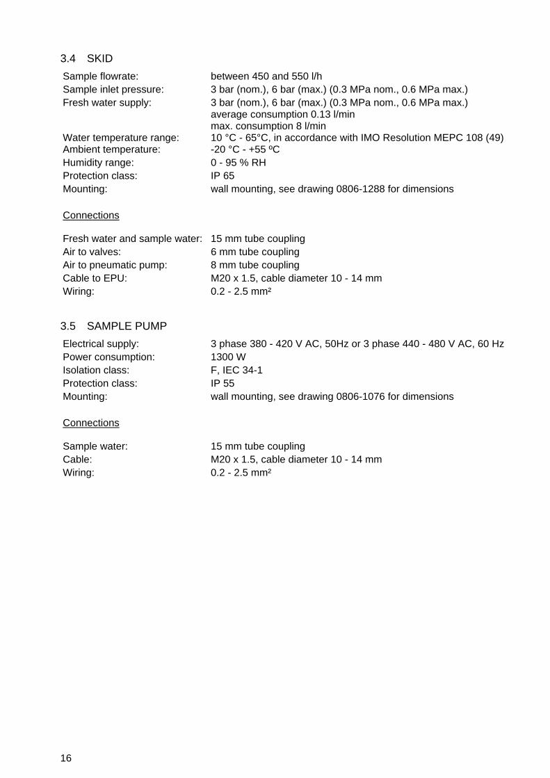
3.4 SKID
Sample flowrate: between 450 and 550 l/h Sample inlet pressure: 3 bar (nom.), 6 bar (max.) (0.3 MPa nom., 0.6 MPa max.) Fresh water supply: 3 bar (nom.), 6 bar (max.) (0.3 MPa nom., 0.6 MPa max.)
average consumption 0.13 l/min max. consumption 8 l/min
Water temperature range: 10 °C - 65°C, in accordance with IMO Resolution MEPC 108 (49) Ambient temperature: -20 °C - +55 ºC Humidity range: 0 - 95 % RH Protection class: IP 65 Mounting: wall mounting, see drawing 0806-1288 for dimensions Connections
Fresh water and sample water: 15 mm tube coupling Air to valves: 6 mm tube coupling Air to pneumatic pump: 8 mm tube coupling Cable to EPU: M20 x 1.5, cable diameter 10 - 14 mm Wiring: 0.2 - 2.5 mm²
3.5 SAMPLE PUMP
Electrical supply: 3 phase 380 - 420 V AC, 50Hz or 3 phase 440 - 480 V AC, 60 Hz Power consumption: 1300 W Isolation class: F, IEC 34-1 Protection class: IP 55 Mounting: wall mounting, see drawing 0806-1076 for dimensions Connections
Sample water: 15 mm tube coupling Cable: M20 x 1.5, cable diameter 10 - 14 mm Wiring: 0.2 - 2.5 mm²

17
3.6 REFERENCE TABLE OF PRODUCTS WHICH MAY BE MEASURED
Crude oils, and “black” and “white” products (Annex I):
Range number
Chemical
0
Marine Distillate Fuel oil
1
Category 1 crude oil
2
Category 2 crude oil
3
Category 3 crude oil
4
Category 4 crude oil
5
Category 5 crude oil
6
Category 6 crude oil
7
Automotive Gasoline
8
Kerosine
Other products or applications (Annex II):
Range number
Chemical Range number Chemical
9
Cyclohexane 20 Hexene
10
Cyclohexene 21 iso-Octane (all isomers)
11
Cyclopentane 22 Methylcyclohexane
12
Cyclopentene 23 Nonane
13
p-Cymene 24 Parafinne
14
Diethylbenzene 25 Pentane
15
Dipentene 26 Pentene
16
Dodecane 27 Toluene
17
Ethylbenzene 28 TetraHydroNaphtalene
18
Ethylcyclohexane 29 Xylene (all isomers)
19
Hexane 30 Orimulsion
31 Calibration VAF
18
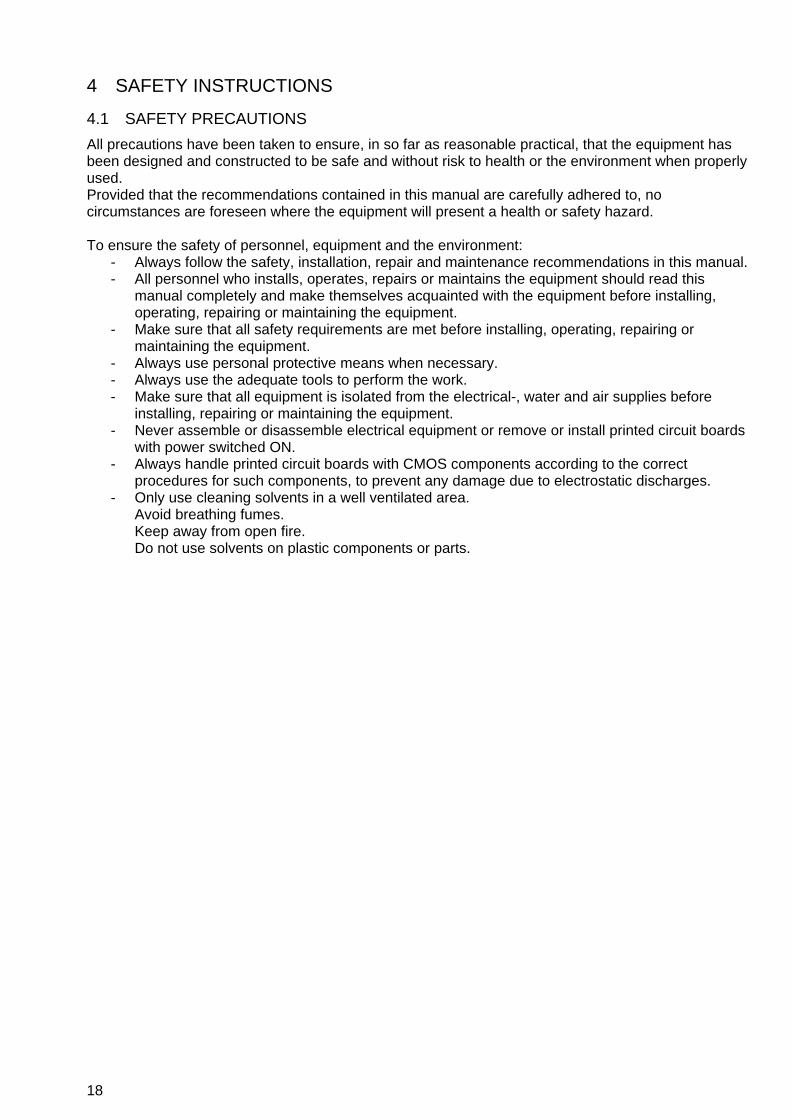
4 SAFETY INSTRUCTIONS
4.1 SAFETY PRECAUTIONS
All precautions have been taken to ensure, in so far as reasonable practical, that the equipment has been designed and constructed to be safe and without risk to health or the environment when properly used. Provided that the recommendations contained in this manual are carefully adhered to, no circumstances are foreseen where the equipment will present a health or safety hazard. To ensure the safety of personnel, equipment and the environment:
- Always follow the safety, installation, repair and maintenance recommendations in this manual. - All personnel who installs, operates, repairs or maintains the equipment should read this
manual completely and make themselves acquainted with the equipment before installing, operating, repairing or maintaining the equipment.
- Make sure that all safety requirements are met before installing, operating, repairing or maintaining the equipment.
- Always use personal protective means when necessary. - Always use the adequate tools to perform the work. - Make sure that all equipment is isolated from the electrical-, water and air supplies before
installing, repairing or maintaining the equipment. - Never assemble or disassemble electrical equipment or remove or install printed circuit boards
with power switched ON. - Always handle printed circuit boards with CMOS components according to the correct
procedures for such components, to prevent any damage due to electrostatic discharges. - Only use cleaning solvents in a well ventilated area.
Avoid breathing fumes. Keep away from open fire. Do not use solvents on plastic components or parts.

19
5 UNPACKING Let the equipment acclimatize inside the closed box for at least one hour at the location where the Oilcon® Oil Discharge Monitoring and Control System will be installed. When the equipment is taken out of the box, please leave the special protection supplied with the equipment as long as possible in place to avoid any damage. Disposal of the packing material should be done according to local laws or regulations, or according to the rules that are applicable on the vessel. Details of main components of the Oilcon® Oil Discharge Monitoring and Control System: Main Control Unit Weight: 1.5 kg Dimensions: 257 mm x 157 mm x 126 mm (W x H x D)
Figure 1 Main Control Unit
Electro Pneumatic Unit Weight: 9.5 kg Dimensions: 500 mm x 263 mm x 114 mm (W x H x D)
Figure 2 Electro Pneumatic Unit
Motor Starter Box Weight: 1 kg Dimensions: 126 mm x 176 mm x 100 mm (W x H x D)
Figure 3 Starterbox
Electronic Differential Pressure Transmitter Weight: 8 kg Dimensions: 225 mm x 195 mm x 194 mm (W x H x D)
Figure 4 Electronic Differential Pressure Transmitter

20
Orifice Plate Thickness: 6 mm Material: Stainless Steel Diameter and bore: Specific to each installation
Figure 5 Electronic Differential Pressure Transmitter and Orifice Plate
Skid Assembly Weight: 20 kg Dimensions: 500 mm x 420 mm x 177 mm (W x H x D) Air Connections: 6 mm and 10 mm tube Water connections: 15 mm OD tube
Figure 6 Skid Assembly Sampling Pump Weight: 30 kg Length overall: 348 mm Cut out diameter: 290 mm Connections: 15 mm OD tube
Figure 7 Sampling Pump
Total weight of the complete system: 87 kg
21
6 INSTALLATION
6.1 INTRODUCTION
This specification sets out the requirements for the installation, operation and maintenance of an Oilcon® Oil Discharge Monitoring and Control System on board a typical tanker. It should be studied carefully before actually commencing any operation or work. For the purpose of installation the system can be divided into 4 categories:
1. Pump room equipment and related deck ancillaries (hazardous area) 2. Bulkhead penetrations. 3. Engine room equipment * (non-hazardous area) 4. Control room equipment ** (non-hazardous area)
The exact location of the separate elements within these categories will vary from ship to ship but the specific location of some units relative to others is important. In addition to safety precautions which must always be strictly observed for work in hazardous spaces, installation undertaken at sea, with the ship underway, require additional precautions. * It is recognised that for some vessels the pump room and engine room are not adjacent. If this
is the case, it will be necessary to mount the electrical equipment in some other suitable non-hazardous space adjacent to the pump room.
** Again, some vessels may not have a cargo control room. If this is the case, some other convenient area must be identified, such as the navigation bridge, the engine room or the accommodation area.
CAUTION: ANY COMPONENTS MOUNTED ON OPEN DECK OR IN AREAS LIKELY TO ENCOUNTER TEMPERATURE AT OR BELOW FREEZING SHOULD BE PROTECTED ACCORDINGLY AGAINST FREEZING.
6.2 UTILITIES
For operation of the Oilcon® Oil Discharge Monitoring and Control System the following utilities are required:
6.2.1 Fresh water supply
An uninterrupted supply of fresh water free of any contamination is important for a correct operation of the Oilcon® Oil Discharge Monitoring and Control System, as the freshwater is used to keep the pipework and the windows of the detection cell clean and to perform a Zero check prior to operation of the system. Fresh water supply conditions: Nominal inlet pressure: 1.5 bar (0.15 MPa) Maximum inlet pressure: 6 bar (0.6 MPa) Average consumption: 0.13 l/min Maximum consumption: 8 l/min, during FLUSH Water temperature range: 10 °C - 65 °C

22
6.2.2 Air supply
For a trouble free and satisfactory operation of the pneumatic components in the Oilcon® Oil Discharge Monitoring and Control System a supply of clean, dry air at a constant pressure is essential. Air supply conditions EPU: Valve control: 4.0 bar nom., 7 bar max. (0.4 MPa nom., 0.7 MPa max.) Window wash pump: 4.0 bar nom., 7 bar max. (0.4 MPa nom., 0.7 MPa max.) Average consumption: 6 l/min Maximum consumption: 50 l/min
6.2.3 Electrical supply
electrical supply conditions: Main Control Unit 24 V DC, 0.1 A Emergency supply 24 V DC, 0.1 A Electro Pneumatic Unit 115/230 V AC, 50/60 Hz, 0.5 A Sample pump motor 3 phase 380 - 420 V AC, 50 Hz, 1.1 kW, 2.6 A
or 3 phase 440 - 480 V AC, 60 Hz, 1.3 kW, 2.5 A
NOTE: AR REQUIRED BY REGULATIONS THE EMERGENY POWER SUPPLY HAS TO ORIGINATE FROM A SOURCE INDEPENDENT FROM THE SOURCE OF THE MAIN POWER SUPPLY.
6.3 PIPEWORK GENERAL
All pipework for water services should be of a suitable material and capable of withstanding working pressures of up to 16 bar. The pipework has been standardised at 15 mm O.D. with a minimum wall thickness of 1 mm. For example: ASTM B111-69 alloy 706 - or BS 378/2871 type CN 102-0. Air signal pipework should be copper, and generally be 6 mm O.D. x 4 mm I.D. The exception in this sizing is the air supply for the window wash pump mounted on the skid, and shown as V12. These lines are 8 mm O.D. x 6 mm I.D. (ASTM B75-68 alloy 122 - or BS 2871/1971 type C106-0). Pipework must be clean and oil free prior to fitting and care must be taken to ensure all joints are leak tight. Failure to ensure this will adversely affect system function, particularly if air leakage is evident on pump suction lines. Ideally all joints should be made using brazed couplings. If piping is being installed during a sea passage then compression fittings may be used. These couplings should be of a salt water resistant material, and the use of stainless steel compression rings may be necessary if a non-flared tube end technique is used to make the joints. Mild steel couplings must not be used. Pipework must be adequately clipped and supported, and shall not impose any strain or force on equipment, e.g. pump or skid assembly. Pipework must also be protected in exposed situations. In those cases where the water discharge from the ballast skid is taken to a slop tank, if the ship has an inert gas system, a loop-seal arrangement must be fitted in the discharge line to prevent contamination being forced back down the line. Also measurements must be taken to prevent the discharge from free-falling into the tank. This is usually achieved by diverting the flow against the bulkhead of the tank.

23
CAUTION: BEFORE THE SYSTEM IS PUT INTO OPERATION OR TESTED ALL PIPEWORK MUST BE FLUSHED AND CLEARED FROM DIRT OR FOREIGN MATTER.
Reference drawings:
- Dimensional drawing and parts list ballast skid Mark 6M 0806-1288 - Schematic installation diagram Oilcon Monitor System with
1x dP/I transmitter Mark 6 0806-8068 - Bulkhead penetration and piping diagram Mark 6M 0806-8069
6.3.1 Sample pump unit
The sample pump unit comprises a pump, bulkhead mounting flange with integral gastight shaft seal and a flange mounted motor. For this purpose a hole with a diameter of 290 mm is to be made in the bulkhead wall. The pump unit shall be fitted to the bulkhead utilising the welding ring as supplied with the pump. This ring shall be welded to the bulkhead wall. For the location of this hole verify with the pump dimensional drawing that there will be no obstacles, and that the pump unit can be accessed for maintenance. Maintain sufficient free space around the motor for free air circulation to cool the motor. If possible, the unit should be located below all proposed sampling points and as central to these locations as possible. Care should be taken to ensure that under all operational circumstances a zero or positive pressure is present at the suction side of the pump. The joints of the suction line must be airtight, otherwise air leakage will occur causing reduced pumping and monitoring performance. If air leakage is considerable, the pump may fail to prime or pump at all. It will be observed that a length restriction has been placed on the sample pipes (refer to section 6.7.4 pipe work response time calculation) for two reasons:
a. To ensure that the total response time of the system is less than 40 seconds, as required by legislation. In fact, since the instrument response time is less than 5 seconds and the sample velocity in the specified pipework is 0.9 m/s, there is some margin here.
b. To ensure that the sample pump is not faced with excessive negative suction pressure due to high pipe losses.
6.3.2 Installation of the sample pump
WARNING: IN THE CASE OF AN INSTALLATION AT SEA, WHERE THE PUMP ROOM CONSTITUTES A HAZARDOUS AREA, PRECAUTIONS FOR HOT WORK AS LAID DOWN BY THE OWNER MUST BE STRICTLY OBSERVED.
At the selected location a hole with a diameter of 290 mm is to be made in the bulkhead wall. The installer should note that in some circumstance it may be necessary to construct a “top-hat” device, to artificially extend the pump room/engine room bulkhead around the pump/motor assembly while the hole is being cut and the mounting flange fitted. Weld-on the welding ring; make sure that the bolt holes are in X - position. These holes are not to be in + - position! The gasket shall be placed in between the pump main plate and the welded ring. For easy installation do not fit the oil reservoir yet. Before connecting the system piping to the pump, the unit is to be securely fastened to the bulkhead. Long or heavy piping sections shall not be supported from the pump but by separate supports.

24
ALIGNMENT: No inspection or corrections to pump/motor alignment are necessary. Install the oil reservoir and top up the reservoir with the supplied oil.
WARNING: THE OIL RESERVOIR SHALL ALWAYS BE SUFFICIENTLY FILLED WITH OIL, AS THE PROPER FUNCTIONING OF THE GAS SEAL LOCATED IN THE CENTRE OF THE PUMP MAIN PLATE RELIES ON THE PRESENCE OF OIL, FOR LUBRICATING, SEALING AND COOLING PURPOSES.
6.3.3 Electrical installation pump
Verify the power supply. This is to match the data as shown on the electric motor nameplate. Grounding is to be carried out utilizing the grounding bolt located inside the terminal box, before the motor is connected to the mains.
6.3.4 First start
CAUTION: UNDER NO CIRCUMSTANCES SHOULD THE PUMP RUN WITHOUT LIQUID. THE PUMP HOUSING MUST FIRST BE FILLED WITH LIQUID, OTHERWISE THE PUMP WILL SEIZE AND DAMAGE WILL OCCUR..
6.3.4.1 Self priming The pump will not function or prime until the casing is filled with liquid. Make sure any discharge valve is opened before starting, enabling air to be released. Running the pump with zero capacity will cause excessive system pressure; heat generated in the pump and may overload the electric motor. Make sure any system valve should be fully opened when the pump is being started or stopped.
6.3.4.2 Direction of rotation This can be seen or checked from the motor side only. Make sure that all piping is installed, and the pump is filled with water. Switch-on the pump unit for a short moment only! Look at the motor fan and notice the direction in which the fan spins. This must be clockwise, when looking from the back cover of the motor. An arrow also indicates correct direction of rotation. If direction of rotation is wrong, interchange any of two line wires of the power cable in the terminal box. Reference drawings:
- Dimensional drawing sample pump/motor Ballast Monitor Mark 6 0806-1076 - Electrical connection diagram Ballast Monitor Mark 6M MEPC 108(49) 0806-2048 - Schematic installation diagram Oilcon Monitor System with
1x dP/I transmitter Mark 6 0806-8068 - Bulkhead penetration and piping diagram Mark 6M 0806-8069

25
6.3.5 Skid
The skid is normally located in the pump room and is mounted on the pump room/engine room bulkhead. The unit should be positioned above the sample pump, but should be kept below the level of the sampling probe points wherever possible. This is to ensure full pipework and provision of adequate suction pressure for the pump. The skid is provided with four mounting points, drilled to accept 12 mm bolts. A sample point should be fitted between the pump discharge and the skid to facilitate the taking of grab samples for analysis. Reference drawings:
- Dimensional drawing and parts list ballast skid Mark 6M 0806-1288 - Schematic installation diagram Oilcon Monitor System with
1x dP/I transmitter Mark 6 0806-8068 - Bulkhead penetration and piping diagram Mark 6M 0806-8069
6.3.6 Sampling probes
WARNING: IN THE CASE OF AN INSTALLATION AT SEA SAFETY PRECAUTIONS MUST BE OBSERVED WHILE DRILLING OPERATIONS TAKE PLACE. IN THE CASE WHERE WELDING IS NOT PERMITTED A SADDLE CLAMP ARRANGEMENT CAN BE UTILISED. THIS TYPE OF PROBE ARRANGEMENT SHOULD ONLY BE VIEWED AS TEMPORARY AND ARRANGEMENTS SHOULD BE MADE TO WELD THE PROBE IN PLACE AT THE NEXT OPPORTUNITY.
Sample point(s) are supplied with the monitor, for location at the selected points on the relevant overboard discharge lines and contains the following:
- A pneumatic operated valve for selection of the sample point; - A sample probe to take the sample from the discharge line.
Each probe is supplied with a hand valve and a compression fitting which can be welded to the pipeline. Positioning of the sample probe within the pipeline is most important. To prevent excessive quantities of air being drawn into the sample pump, the probe should ideally be mounted in a rising vertical pipe section. This will ensure that, provide water is being pumped, the main pipe is always filled. Where it is not possible to mount into a vertical pipe then a horizontal section may be used and the probe located as shown in drawing 0806-1265. VAF Instruments recommend that whenever possible the sample probe should be installed on the upstream side of the orifice plate. In any case the probe should be located upstream of any diverting line to the slop tank. The important points to note are as follows:
- The probe enters from the bottomside of the pipe. - The probe is mounted a small distance into the pipe. This ensures a representative sample and
reduces the possibility of picking up “sludge” deposited in the pipe. - The probe end is located in the lower section of the pipe, partly to increase the possibility of
obtaining an air-free sample and partly to reduce the obstruction in the pipe. - The sample valve is mounted in the correct orientation. (Air inlet port uppermost) - The sample valve inlet and outlet ports are correctly mounted.

26
Reference drawings: - Dimensional drawing sample valve Mark 6 0806-1077 - Part list sampling probe pipe connection Ø15 mm Ballast Monitor Mark 6M 0806-1265 - Schematic installation diagram Oilcon Monitor System with
1x dP/I transmitter Mark 6 0806-8068
6.3.7 Orifice plate
6.3.7.1 General information The orifice plate is a square-edged, concentric bore type, manufactured in stainless steel. It is designed to be clamped between two flanges, within the PCD of the flange bolts. Working pressure is up to 24 bar and working temperature is up to 290 °C. Width is 3 mm on this vessels line size. In such cases where a bevel is machined on the bore of the plate, the side with the bevel on should be facing downstream when installed.
6.3.7.2 Installation of flow sensor The single most important consideration, when installing an orifice plate type flowmeter is the amount of straight pipe available on each side of the orifice plate. It is appreciated that long lengths of straight pipe are not common in the average pump room, but it is essential that the flow through the orifice plate is not turbulent. The only way to achieve this is, to have a long smooth approach to the orifice plate. The minimum recommended length of straight pipe upstream of the plate is 10 x pipe diameters and downstream of the plate, is 5 x pipe diameters. Within these distances there should be no bends or obstructions such as valves. The effect of reducing these distances is a considerable reduction of the accuracy of the flowmetering system. The accuracy of the flowmeter is limited to +/- 10 % and this is easily achieved at high flow rates. However, at low flow rates, an orifice plate type flowmeter rapidly becomes inaccurate such that the accuracy limit of +/- 10 % is reached at about 1/10th of the maximum flow. If the orifice plate is not installed with adequate lengths of straight pipe, the effect is a reduction of the effective measuring range of the flowmeter and a widely fluctuating signal. The orifice plate should be mounted in such a position so as to ensure a full pipe at all times, which is usually best achieved in a vertical pipe. The pipeline downstream of the sensor must be arranged to ensure that no siphoning effect is possible. To prevent siphoning in horizontal installations, the discharge line must rise by at least 1 x pipe diameter above horizontal centre line. The rise should be so arranged that it is located at least 5 x pipe diameters after the orifice plate. It must be stressed that if above installation requirements cannot be met, VAF Instruments should be consulted for advice. VAF Instruments cannot held be responsible for any flowmetering system installed incorrectly or without due consultation. The orifice plate is installed between the flanges using jointing material of 1.5 mm thickness. Two pressure tapping holes are required, one on each side of the orifice plate. For pipelines larger than 25 mm diameter, it is advisable to weld a threaded boss to the pipeline. For lines less than 25 mm diameter the pipe itself can be drilled and tapped. In both cases, the hole must be threaded for ¼” BSP. The boss upstream of the orifice plate must be sited 1 x pipe diameter from the centre-line of the plate. The boss downstream of the orifice plate must be sited ½ x pipe diameter from the centre line of the plate. In the case of a vertically rising line, the bosses can be sited at any position on the circumference of the pipe. In a horizontal line, the bosses must be sited on the horizontal centre line of the pipe.
27
Reference drawings: - Dimensional drawing ball valve flowmeter kit Ballast Monitor 0806-1041 - Installation flowmeter Ballast Monitor Mark 5/6 0806-8016 - Schematic installation diagram Oilcon Monitor System with
1x dP/I transmitter Mark 6 0806-8068
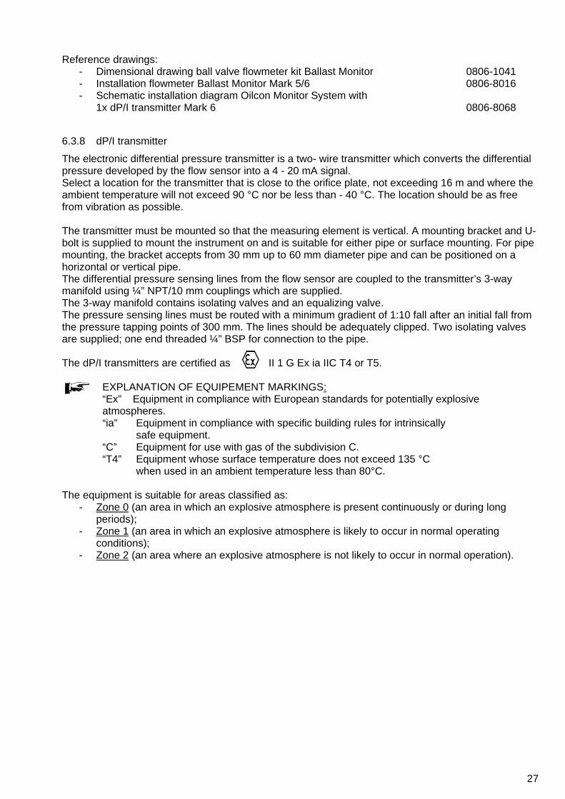
6.3.8 dP/I transmitter
The electronic differential pressure transmitter is a two- wire transmitter which converts the differential pressure developed by the flow sensor into a 4 - 20 mA signal. Select a location for the transmitter that is close to the orifice plate, not exceeding 16 m and where the ambient temperature will not exceed 90 °C nor be less than - 40 °C. The location should be as free from vibration as possible. The transmitter must be mounted so that the measuring element is vertical. A mounting bracket and U-bolt is supplied to mount the instrument on and is suitable for either pipe or surface mounting. For pipe mounting, the bracket accepts from 30 mm up to 60 mm diameter pipe and can be positioned on a horizontal or vertical pipe. The differential pressure sensing lines from the flow sensor are coupled to the transmitter’s 3-way manifold using ¼” NPT/10 mm couplings which are supplied. The 3-way manifold contains isolating valves and an equalizing valve. The pressure sensing lines must be routed with a minimum gradient of 1:10 fall after an initial fall from the pressure tapping points of 300 mm. The lines should be adequately clipped. Two isolating valves are supplied; one end threaded ¼” BSP for connection to the pipe. The dP/I transmitters are certified as II 1 G Ex ia IIC T4 or T5.
EXPLANATION OF EQUIPEMENT MARKINGS: “Ex” Equipment in compliance with European standards for potentially explosive atmospheres. “ia” Equipment in compliance with specific building rules for intrinsically
safe equipment. “C” Equipment for use with gas of the subdivision C. “T4” Equipment whose surface temperature does not exceed 135 °C
when used in an ambient temperature less than 80°C. The equipment is suitable for areas classified as:
- Zone 0 (an area in which an explosive atmosphere is present continuously or during long periods);
- Zone 1 (an area in which an explosive atmosphere is likely to occur in normal operating conditions);
- Zone 2 (an area where an explosive atmosphere is not likely to occur in normal operation).

28
WARNING: IN HAZARDOUS ZONES WITH EXPLOSION PROOF REQUIREMENTS THE COVERS MUST BE TIGHTENED WITH AT LEAST 7 TURNS. IN HAZARDOUS ZONES WITH INTRINSICALLY SAFE OR NON-INCENDIVE REQUIREMENTS, THE CIRCUIT ENTITY PARAMETERS AND APPLICABLE INSTALLATION PROCEDURES MUST BE OBSERVED. CABLE ACCESS TO WIRING CONNECTIONS IS OBTAINED BY ONE OF THE TWO CABLE CONDUIT OUTLETS. CONDUIT THREADS SHOULD BE SEALED BY MEANS OF CODE APPROVED SEALING METHODS. THE UNUSED OUTLET CONNECTION SHOULD BE PLUGGED ACCORDINGLY. REFER TO SECTION 6.4.3 OF THIS MANUAL FOR FURTHER INFORMATION.
Reference drawings:
- Control drawing for Mark 6M Oil Discharge Monitor 0806-0005 - Electrical connection diagram Ballast Monitor Mark 6M MEPC 108(49) 0806-2048 - Schematic installation diagram Oilcon Monitor System with
1x dP/I transmitter Mark 6 0806-8068 - Bulkhead penetration and piping diagram Mark 6M 0806-8069 - Connection diagram dP/I Transmitter type FUJI 0810-2010 - Dimensional drawing dP/I transmitter FUJI flowmeter kit
Ballast Monitor Mark 5/6 0899-1092
6.4 BULKHEAD PENETRATIONS GENERAL
Great attention has been paid, during the design of the Oilcon® Oil Discharge Monitoring and Control System to minimise the number of bulkhead penetrations which must be made and to make the total installation as simple and as straightforward as possible. Nevertheless, two sets of penetrations which must be made.
6.4.1 Sample pump
The requirements for mounting this pump have been detailed in section 6.3.1 of this manual.
6.4.2 Air pipelines
The recommended method for making these penetrations is, using a proprietary transit system, for which approvals have been obtained such as the Multi Cable Transit system. It is anticipated that the penetrations will usually be made with standard 6 mm and 10 mm pipe provided with a pipe connector at each side. When the Oilcon® installation is required to be proven with oil injection, a commissioning engineer must make connections to the air supply line V11, on both sides of the bulkhead. The installers are therefore requested: To make at least the V11 bulkhead penetration using a 6 mm pipe connector, one on each side of the bulkhead penetration. Note that these components are outside VAF Instrument’s normal scope of supply. Reference drawings:
- Schematic installation diagram Oilcon Monitor System with 1x dP/I transmitter Mark 6 0806-8068
- Bulkhead penetration and piping diagram Mark 6M 0806-8069 - Multi cable transit Ballast Monitor Mark 6 0806-8070 - Parts list air supply units Ballast Monitor Mark 6 0899-1258
29
6.4.3 I/S signal cable
For general information, the signal cable between the EPU and the skid has a nominal 0.5 mm² diameter, 7 cores of 2 twisted pairs with an overall screen. (EG Helkama RFE-HF60V). The signal cable makes use of the same cable transit system as is used for the air pipelines to ease installation of the system.
BEFORE OPERATION: It is vital to ensure that the equipment supplied exactly meets your needs and that it is certified for a safe use in your expected operating conditions. For the components such as the measurement cell and EPU items of equipment are certified. See section 16 for certification standards.
All circuits are connected to the energy limiting circuits within the EPU. These circuits limit the voltage by means redundant zener diodes, all connected to the same ground connection. The current is limited by means of resistors. Each circuit is thermally protected by means of a fuse. The ratings of the circuits to the measurement cell is such that even in case of an total short circuit of all the circuits together, the energy within that short is still within non-ignitive intrinsically save energy levels (including a safety factor of 1.5) The additional position detection circuits are separated from the circuits to the measurement cell. The EPU contains two other energy limited circuits for connection to the approved dP/I sensors. These circuits are separated from the aforementioned circuits.
WIRING PROCEDURE: Prior to initiating work on the wiring, be sure to turn OFF the main power. Cables, cable glands and plugs certified in accordance with the considered zone must be used. More, whatever the protection mode, only use plugs or cable glands with a protection degree of at least IP 65. - Be sure that the cable diameter complies with the selected cable gland. - Tighten the cable gland in accordance with supplier’s instructions. - Never forget to mount the covers and tighten then correctly.
REPLACEMENT PARTS: The replacement of components can only be done by personnel trained to act on equipment intended for use in potentially explosive atmospheres. Spare parts must only be genuine parts supplied by VAF Instruments. During installation there is no need to operate the system and thus to switch the EPU on.
Reference drawings:
- Control drawing for Mark 6M Oil Discharge Monitor 0806-0005 - Schematic installation diagram Oilcon Monitor System with
1x dP/I transmitter Mark 6 0806-8068 - Bulkhead penetration and piping diagram Mark 6M 0806-8069 - Multi cable transit Ballast Monitor Mark 6 0806-8070

30
6.5 ELECTRICAL INSTALLATION GENERAL
CAUTION: ALL CABLES MUST BE OF SUITABLE TYPE FOR THE PURPOSE INTENDED.
All cables should be run on cable trays and should be secured to the tray by clips which will not damage the cable sheathing. Metal clips are not recommended, unless coated with a suitable buffer material such as nylon or PVC. All screened cables should be run on a separate cable tray, if possible. Under all circumstances screened cables must be kept segregated from AC power cables, at a minimum distance of 0.5 m. All cables passing through bulkheads should be led through an approved gastight bulkhead penetration/gland. To avoid signal fouling due to electromagnetic induction, all braided copper screens on the screened cables should be connected at one end only, in the engine room. All exposed braids should be suitably trimmed and finished so that all braids end inside the cable gland, and no braids should enter into the cabinet.
NOTE: - Make sure the temperature rating of the cables connected to the EPU should at least be
70 ºc. - The supply cables connected to the EPU should be secured in such a way that no
connection can be made with the signal cables. - For correct installation a suitable isolation switch shall be installed in the supply line as
near as possible to the equipment. Maximum fuse current 16 A. Cable terminations for individual conductors should be finished with a pin terminal crimped on the conductor. Cables are not supplied by VAF Instruments, unless specifically ordered.
6.5.1 Electro Pneumatic Unit (EPU)
NOTE: All wiring connected to EPU from the hazardous zone must be connected in accordance with drawing 0806-0005 in order to ensure intrinsically safe circuits remain safe.
The EPU is of a sheet steel construction, it is mounted onto a steel frame which carries the pneumatic section of the assembly. It is normally situated in the engine room on the engine room/pump room bulkhead, opposite the skid mounted in the pump room. This unit has both electrical and pneumatic connections, the electrical cables being run through the base of the cabinet to internal connectors. Suitable cable glands are provided for in the base of the cabinet. The pneumatic connections are located in the right hand side of the cabinet mounting plate and are suitable for 6 mm O.D. and 10 mm O.D. pipe. Mounting is by means of six holes drilled to accept 8 mm bolts. Should the mounting side selected be subject to excessive vibration, anti-vibration pads or stiffeners should be installed to reduce these vibrations to an acceptable level.

31
6.5.2 Starter box
The starter box is used to switch and control the electrical supply to the sample pump motor and contains a relay and thermal relay to protect the pump for overheating. It may be mounted to any suitable location adjacent to the EPU or pump motor. The unit is mounted by four holes which accept 4 mm bolts. Reference drawings:
- Control drawing for Mark 6M Oil Discharge Monitor 0806-0005 - Dimensional drawing motor starter box Ballast Monitor Mark 6 0806-1075 - Dimensional drawing and parts list EPU 1-2 sample valves Mark 6M 0806-1287 - Connection diagram motor starter box Mark 6 0806-2032 - Electrical connection diagram Ballast Monitor Mark 6M MEPC 108(49) 0806-2048 - Schematic installation diagram Oilcon Monitor System with
1x dP/I transmitter Mark 6 0806-8068 - Bulkhead penetration and piping diagram Mark 6M 0806-8069
6.6 CONTROL ROOM EQUIPMENT – MAIN CONTROL UNIT (MCU)
This unit is normally mounted in the cargo control room and may be fitted into an appropriate space in one of the cargo control consoles, or wall mounted via a suitable wall mount box. The Main control Unit is suitable for mounting into the console.
6.6.1 Speed input
1. The Main Control Unit is designed to accept a GPS NMEA 0183 input, baud rate: 4800, data bits: 8, parity: none, stop bits: 1.
IMPORTANT: The latitude/longitude position command to be set with four (4) digits behind comma.
The following NMEA0183 position messages can be accepted by the Main Control Unit:
- RMC (Recommended Minimum Specific GNSS Data) - GLL (Geographic Position- Latitude/Longitude) - GGA (Global Position System Fix Data)
The following NMEA0183 speed message can be accepted by the Main Control Unit:
- VTG (Course over ground and ground speed)
2. The Main Control Unit is designed to accept a voltage free pulse signal from the ship’s log or a similar device. Input pulses can be either 100, 200 or 400 pulses/NM.
6.6.2 Overboard valve control
The overboard valve is controlled by the MCU. To achieve this, the MCU is provided with a double pole switchover relay contact (discharge control relay) to control the discharge valve operation. The valve feedback signal must be connected to the appropriate input terminal at the back of the MCU. In case of system failure the Auto/Man relay contact can be used to override the MCU command, to switchover to manual operation. The relay contact is controlled by the key switch on front of the MCU. Reference drawings:
- Dimensional drawing MCU Mark 6M 0806-1285 - Electrical connection diagram Ballast Monitor Mark 6M MEPC 108(49) 0806-2048

32
6.7 INSTALLATION CHECKLIST
6.7.1 General installation checks
1. Is all pipework of correct materials and dimensions? 2. Is all pipework adequately supported? 3. Does the maximum distance from furthest sample probe to the skid give a system response
time of less than 40 s? 4. Is all pipework free from leaks? 5. Is the sample discharge line to the slop tank so arranged as to prevent free-fall into the tank? 6. Is the loop-seal (or non-return valve) of adequate height installed in the sample discharge line
to the slop tank? 7. Is the sample pump installed in such a position as to have a positive pressure on the suction
side of the pump at all times? 8. Is the relative position of the sample pump to the skid satisfactory? 9. Is the relative position of the skid to the EPU satisfactory? 10. Are the sample probes adequately supported and fitted with a manual stop valve as well as the
pneumatic select valve? 11. Are the sample probes located in a vertical section of pipe with the flow upwards or in a
horizontal section of pipe with the probe entering from the underside? 12. Are all discharges fitted with a sample probe? 13. Is the positioning of each sample probe at a location upstream of any recirculation line to the
slop tank? 14. Is the sample probe inserted a distance of ¼ of the pipe diameter and is the probe correctly
angled in the direction of the flow? 15. Is the capacity of the fresh water supply adequate? 16. Is the fresh water tank (if installed) made from non-corrosive material of adequate strength? 17. Is the fresh water tank (if installed) located a minimum of 6 m above the skid? 18. Is the fresh water tank (if installed) fitted with an automatic filling valve of adequate size? 19. Are the EPU and the starter box mounted correctly? 20. Are all electrical cables supported adequately? 21. Are all signal cables segregated from AC power cables by at least 0.5 m? 22. Are all cables terminated correctly? 23. Is the Main Control Unit mounted correctly? 24. Are all bulkhead penetrations gastight and of a type approved by the Administration? 25. If a starting interlock is required, has the method been approved by the classification society?
6.7.2 Check of Flowmeter and automatic control
1. Does the flowmeter orifice plate have the required minimum of 10 x pipe diameter upstream and 5 x pipe diameter downstream and has it been installed upstream of any recirculating line to the slop tank?
2. Is the orifice plate located in a vertical section of the pipe with an upwards flow? 3. If the orifice plate is located in a horizontal section of pipe, have measures been taken to
ensure that the pipe will always be full of water, will not be subjected to siphoning and will ensure sufficient back-pressure across the orifice?
4. Is positioning of the orifice plate pressure tapping correct at 1 x pipe diameter upstream and ½ x pipe diameter downstream of the orifice plate?
5. Do the pressure sensing lines from the orifice plate pressure tapping fall continuously to the differential pressure transmitter?
6. Is the automatic control of overboard discharge valve(s) and recirculation valve(s) installed correctly?
7. Are manual stop valves fitted as required?

33
6.7.3 Starting interlock and/or overboard valve control
IMO Resolution MEPC 108 (49) entitled: “Guidelines and specifications for Oilcon® Oil Discharge Monitoring and Control Systems for tankers” Oil tankers of 150 gross tonnage and above shall be fitted with an Oilcon® Oil Discharge Monitoring control system approved by the Administration and designed and installed in compliance with the Gues and Specifications for Oil Discharge Monitoring and Control Systems for Oil Tankers adopted by the Organization. System should record and display the necessary information: Input information: Ship’s position (GPS)
Ship’s speed Overboard discharge valve position Oil content [ppm] Flowrate discharge Time and date Starting interlock
Output information: Time and date (UTC)
Ship’s position (GPS) Auto/manual mode Status of operational mode Instantaneous oil content [ppm] Flowrate of discharge [m³/h] Ship’s speed [kts] Instantaneous rate of discharge of oil [l/NM] Total quantity of oil discharged [l] Status of discharge Sample point selected Type of oil
The data is displayed on a LCD display and also stored in the internal memory Due to the wide variety of starting interlock and overboard discharge control circuits VAF Instruments can only give a general concept of how they can be achieved. Firstly: the IMO description of each version and then an interpretation of the system layout using the Oilcon® Oil Discharge Monitoring and Control System. i) Discharge valve control The definition of an overboard discharge control is given in paragraph 3.3 of the Annex to IMO Resolution MEPC 108 (49) and is as follows: “An overboard discharge control is a device which automatically initiates the sequence to stop the overboard discharge of the effluent in alarm conditions and prevents the discharge throughout the period the alarm condition prevails. The device may be arranged to close the overboard valves or to stop the relevant pumps, as appropriate.”

34
ii) Starting interlock The definition of a starting interlock is given in paragraph 3.4 of the Annex to IMO Resolution MEPC 108 (49) and is as follows: “A starting interlock is a facility which prevents the initiation of the opening of the discharge valve or the operation of other equivalent arrangements before the monitoring system is fully operational when use of the monitoring system is required by the Convention.” By its very nature Overboard Discharge Control can be considered a starting interlock, if the overboard valves are controlled from the Main Control Unit. They will only receive a signal to open for discharge when all the input parameters are correct. If so connected as to stop the discharge by use of stopping the relevant pumps, this is not deemed a starting interlock. In this instance a starting interlock could be typically a valve spindle brake. For an example of an overboard control circuit by use of interlocking overboard and slop tank return valves see drawing 0806-5019. This also incorporates a starting interlock. VAF Instruments advise that prior consultation is made with the classification society surveyor in each case to ensure that the arrangement will be acceptable both as to the operation and with regard to safety.
6.7.4 Pipework response time
MARPOL regulations require that taking into consideration the length of sampling piping, the overall response time is as short as possible, and in any case not more than 40 s. It is therefore necessary to place a restriction on the length of sample pipe from the probe to the detector cell. The maximum length of sample pipe permissible can be calculated as follows:
Total response time: (max)401 sT
Monitor response time: sT 42 Sample response time: The maximum length of sample pipe (in this example the sample pipe outside diameter 15 mm and thickness of the pipe 1 mm):
36003
max
A
QTL
Where: 3T = Sample response time [s]
Q = Sample flowrate [m³/h]
A = Internal area of sample pipe [m²]
sT
TTT
364403
213

35
Internal surface area of the pipe: Sample flowrate: hmQ /³5.0 Therefore:
6.7.5 Final check
Has completed system been inspected as a whole with regard to safety?
mL
L
A
QTL
7.3736001033.1
5.0363600
max
4max
3max
²1033.1
²013.04
²4
013.0
001.02015.0
2
)(001.01
015.015
4 mA
A
dA
md
d
tDd
thicknesswallmmmt
mmmD

36
6.8 OVERVIEW INSTALLATION CHECK
6.8.1 Cable connection Main Control Unit
Reference drawings: - Electrical connection diagram Ballast Monitor Mark 6M MEPC 108(49) 0806-2048 - Connection diagram Oilcon Mark 6 Cable spec. MEPC 108(49) 0806-2050
E D
Screen and tension clamp (see Figure 8):
- The cable must be stripped up to point D - The stripped cable must be inserted in the clamp - The cable must by tightened by using screw E
Signal cable (see Figure 9)
6.8.2 Cable connection Electric Pneumatic Unit
Reference drawings: - Control drawing for Mark 6M Oil Discharge Monitor 0806-0005 - Electrical connection diagram Ballast Monitor Mark 6M MEPC 108(49) 0806-2048
G H I J K L
Figure 10
Figure 9 Figure 8

37
G. Power supply cable IC-07 H. Signal cable IC-03 I. Starter box sample pump cable IC-06 J. Connection cable EPU Skid IC-02 K. Overboard Flowmeter 1 IC-04 L. Overboard Flowmeter 2 IC-04 (if applicable)
N M
N
All cable connections to EPU and Connection Box Skid
- Strip the cable - Guide the stripped cable through the synthetic insert M - Fold back the screen over the synthetic insert M - Push the synthetic insert M in the cable gland N - Tighten the gland nut O
O
Figure 11 Figure 12
Figure 13

38
6.8.3 Intrinsically safe ground points, measurement cell and EPU
Reference drawings: - Control drawing for Mark 6M Oil Discharge Monitor 0806-0005
GND
GND
GND
Figure 14 Figure 15
Figure 16
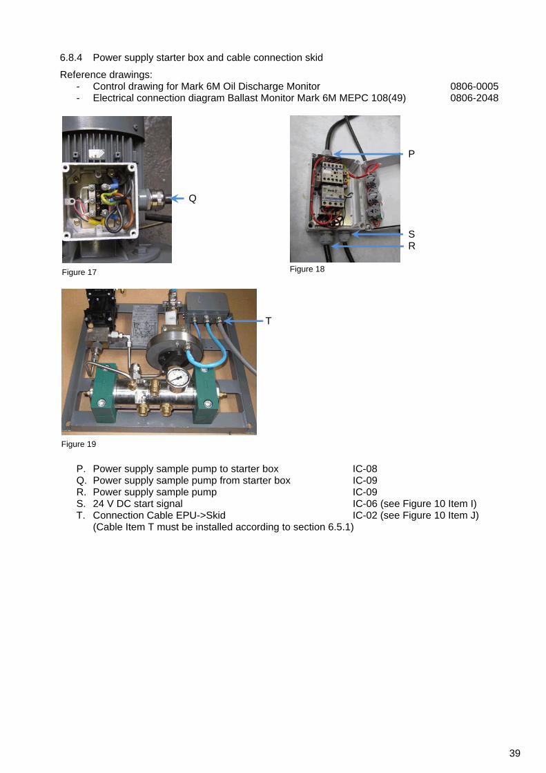
39
6.8.4 Power supply starter box and cable connection skid
Reference drawings: - Control drawing for Mark 6M Oil Discharge Monitor 0806-0005 - Electrical connection diagram Ballast Monitor Mark 6M MEPC 108(49) 0806-2048
Q
P S R
T
P. Power supply sample pump to starter box IC-08 Q. Power supply sample pump from starter box IC-09 R. Power supply sample pump IC-09 S. 24 V DC start signal IC-06 (see Figure 10 Item I) T. Connection Cable EPU->Skid IC-02 (see Figure 10 Item J)
(Cable Item T must be installed according to section 6.5.1)
Figure 19
Figure 18 Figure 17

40
6.8.5 Multi Cable Transit (Bulkhead Penetration)
Reference drawings:
- Multi cable transit Ballast Monitor Mark 6 0806-8070
U
X W V
Y
Installation of MCT
- Place insert-blocks U - Place cables and air pipes in accordance with size of the insert-blocks - Place metal plates V - Place the next line of insert-blocks - When all blocks and cables are installed, place item W - Tighten Nut X - Insert item Y and tighten nuts.
Figure 20 Figure 21
Figure 22
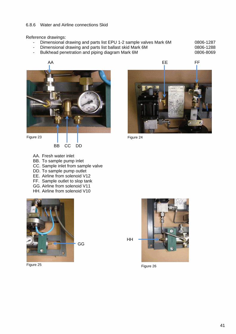
41
6.8.6 Water and Airline connections Skid
Reference drawings:
- Dimensional drawing and parts list EPU 1-2 sample valves Mark 6M 0806-1287 - Dimensional drawing and parts list ballast skid Mark 6M 0806-1288 - Bulkhead penetration and piping diagram Mark 6M 0806-8069
AA
BB CC DD
EE FF
AA. Fresh water inlet BB. To sample pump inlet CC. Sample inlet from sample valve DD. To sample pump outlet EE. Airline from solenoid V12 FF. Sample outlet to slop tank GG. Airline from solenoid V11 HH. Airline from solenoid V10
GG
HH
Figure 23 Figure 24
Figure 25 Figure 26

42
6.8.7 System settings.
JJ
KK
LL
Fresh water regulator
JJ. Water pressure set knob, set pressure to 1,5 bar KK. Fresh water filter
Air regulator
LL. Air pressure set knob, set pressure to 4 bar minimum
MM
Starter Box
MM. Trip level setting
Figure 27 Figure 28
Figure 29

43
7 OPERATING INSTRUCTIONS
7.1 LAYOUT OF THE MCU
Operation of the Oilcon® Oil Discharge Monitoring and Control System is controlled and recorded by the MCU. A representation of the control panel of the MCU, as fitted in the Cargo Control Room, is shown below.
Figure 30 MCU layout The MCU control panel contains the following:
Control key switch USB connector RS-232 serial communication port Reset button Touch screen panel
7.1.1 Control key switch
The control key switch is used to put the MCU in the following modes: - “Control” in this position the MCU is in the normal operational mode, automatically controlling
the ballast discharge system if automatic control is fitted. - “Off” in this position the display is blanked and the MCU goes to a quiescent state. Although the
MCU is in a quiescent state some inputs are still monitored and logged in the internal memory. NOTE: Do not attempt to service the equipment in this mode, see section 8.
- “Console” in this position the MCU is in normal operational mode but manual control of the ballast discharge system is provided from the cargo console. There will be no alarms given and some inputs are still monitored and logged in the internal memory.

44
7.1.2 USB connector
A standard type A, USB connector is fitted to the MCU for copying logged data from the MCU to a USB flash drive. Inside the MCU all operational data is stored in the internal memory. This data can be copied to a USB flash drive following the procedure as describe in section 7.2.1.3. Per year and month a folder is created on the flash drive in which data files, containing the data per day, are copied. The data is stored as plain text and can be opened by any text editor or word processing application on any computer for the purpose of viewing or printing.
7.1.3 Printer port
The print port can be used to connect a serial printer to the MCU. Provided the printer is compatible to the RS232 communication protocol, a printout of operational data can be made at regular intervals. A printout of the data can be made following the procedure as describe in section 7.2.1.3. A printer is not provided by VAF Instruments. Since all data is saved in the internal memory of the MCU and can by copied to a USB flash drive there is no actual need for a printer. The printer port is only fitted to be used as an alternative to copying the data to a USB flash drive.
7.1.4 Reset button
In the rare case the MCU is unresponsive; the reset button can be pushed with e.g. a paperclip to forcibly reboot the MCU. Previously stored data or setting will not be lost during a reboot.
7.1.5 Touch screen panel
The touch screen panel acts as the major interface between the MCU and the operator and displays all relevant information. The touch screen is of the resistive type. In order to activate a key on the screen, a small amount of pressure has to be applied to the key by pressing it.
CAUTION: IN ORDER NOT TO DAMAGE THE TOUCH SCREEN IT IS RECOMMENDED ONLY TO PRESS THE TOUCH SCREEN BY YOUR FINGERS AND NOT BY ANY SHARP OR POINTY OBJECT.

45
7.2 OPERATING THE MCU AND MENU LAYOUT
The MCU has a menu layout as show below.
1.1?
1.2CONFIG
1.3DATA
1.2.1
1.2.2
1.2.3
1.2.4
1.2.5
1.2.6
1.2.7
1.2.8
1.2.9
1.5SETUP
1.5.2.1
1.5.2.2
1.5.2.3
1.3.1PRINTER
1.2.10
1.2.11
1.2.12
1.2.13
1.2.14
1.2.15
1.2.16
1.5.2.4
1.5.2.5
1.5.2.6
1.5.2.7
1.5.2.8
1.5.2.9
1.5.2.10
1.5.2.11
1.5.2.12
1.5.2.13
1.5.3.2.1
1.5.3.2.2
1.5.3.2.3
1.5.3.2.4
1.5.3.2.5
1.5.3.2.6
1.5.3.2.7
1.5.3.2.8
1.5.3.2.9
1.5.3.2CHANGE
1.5.3.3SELFTEST
1.5.3FLUSH
1.5.3.4SAMPLE
1.5.3.4.2STOP
1.5.3.4.3FLUSH
1.5.3.4.4W WASH
1.5.3.5.1SELFTEST
1.5.3.5.2CHANGE
1.5.3.5SAMPLE
1.5.3.5.2.1
1.5.3.5.2.2
1.5.3.5.2.3
1.5.3.5.2.4
1.5.1?
1.3.2USB
1.4SELFTEST
1.5.3.1?
1.5.3.4.1?
1.5.3.0PRE-FLUSH
1STARTUP
0 *WARNING
Figure 31 Menu flowchart * The warning screen (menu 0) only appears if at start up of the MCU, the EPU is not powered on or the communication between the MCU and EPU is faulty.

46
In the different menus the following keys are available: Navigation BACK Previous menu UP Scroll up DOWN Scroll down PRV Previous screen NXT Next screen + Next setting - Previous setting
Menus ? Information screen BUZZER Buzzer test CHANGE Extended setup mode CONFIG Configuration menu DATA Data menu PRINTER Printer menu SELFTEST Self test menu SETUP Setup menu USB USB menu
MORE Next screen
Operations SAMPLE Start sampling operations STOP Stop sampling operations FLUSH Start flush sequence W WASH Start windows wash sequence
Action OK Ok CLR Clear A Automatic ACK Acknowledge With these keys it is possible to navigate through the different menus and change settings. In the following sections, with a step by step walkthrough, is explained how to configure the MCU and how menus are to be used.

47
In the top left corner of the display, the current mode is displayed.
CONTROL Sample point: 1 22-11-11standby Oil type: 5 10:38
Concentration A 0 PPM dischargeFlow A 0 m3/h dirtySkid Flow 0 l/h com: CSpeed A 10.0 kts pos: CDischarge rate 0.0 l/nm segregatedTotal oil 0.0 l com: CLatitude 5321.756N pos: CLongitude 00711.854E
EPU: OKfree: 1927296 kB
SETUP? DATA SELFTESTCONFIG

48
7.2.1 Standby mode (menu 1)
When the MCU and EPU are both powered on and the key switch is turned to the “Control” position, the MCU goes into the standby mode in menu 1.
CONTROL Sample point: 1 22-11-11standby Oil type: 5 10:38
Concentration A 0 PPM dischargeFlow A 0 m3/h dirtySkid Flow 0 l/h com: CSpeed A 10.0 kts pos: CDischarge rate 0.0 l/nm segregatedTotal oil 0.0 l com: CLatitude 5321.756N pos: CLongitude 00711.854E
EPU: OKfree: 1927296 kB
SETUP? DATA SELFTESTCONFIG
Figure 32 Menu 1 The standby mode is also automatically entered after performing the shutdown sequence. In standby mode the system is awaiting manual input from the operator. By pressing the associated keys the following modes can be entered:
- ? Information mode (menu 1.1) - CONFIG Configuration mode (menu 1.2) - DATA Data mode (menu 1.3) - SELFTEST Self test mode (menu 1.4) - SETUP Setup mode (menu 1.5)
By turning the key switch to “OFF” all operations will be stopped. If the MCU is powered on and the EPU is NOT powered on or the communication between the MCU and EPU is faulty, the MCU starts up with a warning screen (Menu 0).
CONTROL Sample point: 1 22-11-11alarm Oil type: 5 10:38
ALARM
EPU No communication
EPU: no communicationfree: 1927296 kB
ACK
Figure 33 Menu 0 After the ACK key is pressed the start up screen is displayed, with the warning that there is no EPU communication. Before the EPU is powered on or communications are restored, no operations are possible. If a GPS signal is present, the current GPS coordinates are shown. Also will the GPS signal set the current date and time.

49
7.2.1.1 Information mode (menu 1.1, 1.5.1, 1.5.3.1 and 1.5.3.5.1) The information mode is entered when the ? key is pressed in the menus 1, 1.5, 1.5.3 or 1.5.3.5. The mode gives additional information about system operation and operational actions which can be taken if e.g. an alarm situation occurs. Depending from which menu the information mode is activated, different texts will be displayed. In case the text is too long to be display all at once, it is possible to scroll through the test with the UP and DOWN keys.
CONTROL Sample point: 1 22-11-11standby Oil type: 5 10:38
version: 0.51S13 & 1.54Before effluent is discharged into the sea, thismonitor system should be fully operational.This means that all parameters must be checkedand an automatic zero calibration is done.Take care that the complete system is connected tothe electrical supply and clean water is availableto the monitor. The SETUP is used to set operational parameters ofthe system, which may be different with everydischarge run. Each parameter setting is given by ? inSETUP for correct operator action to input thatparameter.SELFTEST gives an indication of the alarm and error
EPU: OKfree: 1927296 kB
DOWNUPBACK
In menu 1.1 a short description about the use of the MCU is given:
Before effluent is discharged into the sea, this monitor system should be fully operational. This means that all parameters must be checked and an automatic zero calibration is done. Take care that the complete system is connected to the electrical supply and clean water is available to the monitor. The SETUP is used to set operational parameters of the system, which may be different with every discharge run. Each parameter setting is given by ? in SETUP for correct operator action to input that parameter. SELFTEST gives an indication of the alarm and error status of the system. The function of the buzzer can be checked by SELFTEST. Flush mode This Flush mode is used to check the condition of the detector cell and to calibrate the monitoring system. The total flush time is 4-5 minutes. The flush time is indicated in the display. Care should be taken that clean water supplied to the system is free from any contamination. Idle In the Idle mode the system is ready for sampling and is waiting for a command. The commands in Idle mode are: Selection of (extra) SETUP by CHANGE Selection of SELFTEST Start Sampling by SAMPLE. Sample In the sample mode the system is monitoring the discharge ballast water from the selected sample point. During sample a 9 second automatic window wash takes place every 3 minutes, indicated by window wash. Other commands in Sample are: Stop operation by STOP. Calibration of the system by FLUSH Manual window wash by WINDOW WASH Selection of SELFTEST Selection of (extra) SETUP by CHANGE

50
7.2.1.2 Configuration mode (menu 1.2) The configuration mode is entered when the CONFIG key is pressed in the menu 1. The mode is used to set up the system during installation and this should only be done by a trained service engineer. Prior to entering the settings, the operator must familiarise themselves with the system and also the following information. The majority of this information can be located on the vessel’s IOPP certificate:
- Max range of flowmeter (if fitted); - Pulses per nautical mile, ship’s speed log input (if fitted), ship’s GPS; - Ship’s deadweight; - Status of the ship; - How many sampling points are fitted on the vessel and the denomination of each.
In order to configure the system to the ship’s specific requirements it is necessary to enter specific parameter setting.
CONTROL 22-11-11config Oil type: 5 10:38
Enter code: X X X
BACK 3210
654CLR
987OK
To enter the parameter setting:
- The system has to be in the standby mode - Press the CONFIG key to enter the setup mode (Menu 1.2) - Enter password: 729
In the configuration mode the settings can be changed by either entering a numeric value or by selecting a preset value. Different preset values can be selected by pressing + or -. Selecting a different setting is done by pressing the PRV or NXT key and thereby scrolling through the different settings. For example, by entering a numeric value with the 0...9 keys the setting for the maximum flow of Flowmeter 1 at 20 mA (menu 1.2.1) can be entered.
CONTROL 22-11-11config Oil type: 5 10:38
Max. flow Flowmeter 1 at 20 mA
range 0 ..32000 m3/h
550 m3/h
OK 3210
654CLR
987
NXT
PRV
By pressing the CLR key the value is cleared after which the setting can be entered. When the PRV or NXT key is pressed, the previous or next setting is selected and value entered in the current menu is automatically stored.

51
Next the following settings in the configuration menu (menu 1.2.1 – 1.2.16) can be set: Menu Description Range Remark1.2.1 Max. flow Flowmeter 1 at 20 mA 0...32,000 m3/h The value to be entered is the maximum flow of the
overboard discharge flow connected to the Oil discharge monitoring and control system, if fitted.
1.2.2 Max. flow Flowmeter 2 at 20 mA 0...32,000 m3/h The value to be entered is the maximum flow of the overboard discharge flow connected to the Oil discharge monitoring and control system, if fitted.
1.2.3 K-factor skid flow meter 0…10,000 pulse/l THIS FACTOR MAY NOT BE CHANGEDThis is the k-factor of the flow meter (flow sensor) installed in the skid.This factor is normally factory set and is mentioned on tag plate of flow meter (flow sensor).
1.2.4 Flow Configuration Separated / Combined This function makes it possible to combine two flow meters, if fitted.The system will choose the correct flow metering system based on current flow rate.See drawing 0806-8064 for configuration of the combined or separated system.
1.2.5 K-factor measuring cell 0…10,000 THIS FACTOR MAY NOT BE CHANGEDThis is the k-factor of the measurement cell installed in the skid.This factor is normally factory set and is mentioned on tag plate of cell.
1.2.6 Ship speed GPS / Ship's log The value entered determines whether the input of the GPS or the ship's log is used to calculate the ship's speed.
1.2.7 K-factor Ships log 0…400 pulse/NM The value entered is the input in pulses/nautical mile from the vessel's speed log (if installed).
1.2.8 Total ship's volume 0…600 kTon The Value to be entered is the ships deadweight in kilo tons. In other words if the deadweight is 45,000 tons, a value of 45 must be entered.
1.2.9 Status of the ship New / Old Value to be entered is either New or Old based on IOPP certificate Item 1.7
1.2.10 Number of sample points 1…6 The value to be entered is based on the number of sampling points installed on the ship.
1.2.11 - 1.2.16 Name of sample point - port high- starboard high- port low- starboard low- stripping- segregated ballast
The value to be entered is based on the name or nomination of each particular sample point.
The sample points:- port high- starboard high- port low- starboard low- strippingare used for dirty/clean ballast (Relay 1 X6)
The sample point:- segregatedis used for segregated ballast (Relay 0 X7)

52
7.2.1.3 Data mode (menu 1.3) The data mode is entered when the DATA key is pressed in the menu 1. The mode is used to print out logged data with a printer or copy this data to a USB flash drive. In the data mode a selection has to be made whether the data is printed to a printer or copied to a USB flash drive.
CONTROL Sample point: 1 22-11-11data Oil type: 5 10:38
USBPRINTERBACK
When a selection has been made, two dates in either menu 1.3.1 or menu 1.3.2 have to be set to mark the begin date and end date of the logged data to be printed or copied. The data format used is DD – mm – YYYY.
CONTROL Sample point: 1 22-11-11data Oil type: 5 10:38
Start: 07 - 10 - 2011
End: 22 - 11 - 2011
BACK
-NXT
PRV +
OK
During the printing or copying no keys are available on the display. When the printing or copying has finished, the keys will reappear.
CONTROL Sample point: 1 22-11-11data Oil type: 5 10:38
2011/11/dat07.bin - processing - copied2011/11/dat08.bin - processing - copied2011/11/dat10.bin - processing - copied2011/11/dat16.bin - processing - copied2011/11/dat17.bin - processing - copied2011/11/dat21.bin - processing - copied
USBPRINTERBACK
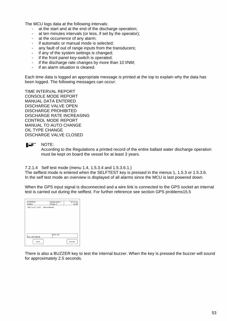
53
The MCU logs data at the following intervals: - at the start and at the end of the discharge operation; - at ten minutes intervals (or less, if set by the operator); - at the occurrence of any alarm; - if automatic or manual mode is selected; - any fault of out of range inputs from the transducers; - if any of the system settings is changed; - if the front panel key-switch is operated; - if the discharge rate changes by more than 10 l/NM; - if an alarm situation is cleared.
Each time data is logged an appropriate message is printed at the top to explain why the data has been logged. The following messages can occur: TIME INTERVAL REPORT CONSOLE MODE REPORT MANUAL DATA ENTERED DISCHARGE VALVE OPEN DISCHARGE PROHIBITED DISCHARGE RATE INCREASING CONTROL MODE REPORT MANUAL TO AUTO CHANGE OIL TYPE CHANGE DISCHARGE VALVE CLOSED
NOTE: According to the Regulations a printed record of the entire ballast water discharge operation must be kept on board the vessel for at least 3 years.
7.2.1.4 Self test mode (menu 1.4, 1.5.3.4 and 1.5.3.6.1.) The selftest mode is entered when the SELFTEST key is pressed in the menus 1, 1.5.3 or 1.5.3.6. In the self test mode an overview is displayed of all alarms since the MCU is last powered down. When the GPS input signal is disconnected and a wire link is connected to the GPS socket an internal test is carried out during the selftest. For further reference see section GPS problems15.5
CONTROL Sample point: 1 22-11-11selftest Oil type: 5 10:38
2011-11-21 14:57 - Bad shutdown
EPU: OKfree: 1927296 kB
BUZZERBACK
There is also a BUZZER key to test the internal buzzer. When the key is pressed the buzzer will sound for approximately 2.5 seconds.

54
7.2.1.5 Setup mode (menu 1.5) The setup mode is entered when the SETUP key is pressed in the menu 1. The mode is used to setup the system for a specific discharge operation. When the setup menu is entered, 3 options are available:
- ? information mode (menu 1.5.1) - CHANGE setup mode (menu 1.5.2) - FLUSH calibration flush mode (menu 1.5.3)
When the ? key is pressed, the information mode is entered. When the CHANGE key is pressed, the setup menu allows the operator to change specific parameters. By pressing the FLUSH key the system is set up for sampling and discharging ballast water. Before the MCU goes into sampling mode, the system is flushed and calibrated.
7.2.1.5.1 Information mode (menu 1.5.1, 1.1, 1.5.3.1 and 1.5.3.5.1) The information mode is entered when the ? key is pressed in the menus 1.5, 1, 1.5.3 or 1.5.3.5. The mode gives additional information about system operation and operational actions which can be taken if e.g. an alarm situation occurs. Depending from which menu the information mode is activated, different texts will be displayed.
CONTROL Sample point: 1 22-11-11standby Oil type: 5 10:38
version: 0.51S13 & 1.53Sample pointThis monitor system can select out of 6 possiblesample points for discharging ballast water.Name of sample points is:1) port high2) starboard high3) port low4) starboard low5) stripping6) segregated ballast.Before each discharge it should be checked that thecorrect sample point is selected.
discharge mode
DOWNUPBACK
In menu 1.5.1 a text with short description about the possible sampling points is given:
Sample point This monitor system can select out of 6 possible sample points for discharging ballast water. The names of the sample points are:
1) port high 2) starboard high 3) port low 4) starboard low 5) stripping 6) segregated ballast.
Before each discharge it should be checked that the correct sample point is selected.

55
7.2.1.5.2 Setup mode (menu 1.5.2) The setup mode is entered when the CHANGE key is pressed in the menu 1.5.2.1. In order to setup the system for a specific ballast water discharge, it is necessary to enter specific parameter settings. In the setup mode the settings can be changed by either entering a numeric value or by selecting a preset value. Different preset values can be selected by pressing + or -. Selecting a different setting is done by pressing the PRV or NXT key and thereby scrolling through the different settings.
CONTROL Sample point: 1 22-11-11setup Oil type: 5 10:38
sample pointdischarge modetotal oil limitreset total oildischarge alarmspeed ind. 1 port highflowrate ind.oil typeconc. alarmprinting intervaloil conc. ind.display contrastdate / time
OK
-NXT
PRV +
By pressing the CLR key the value is cleared after which the setting can be entered. When the PRV or NXT key is pressed, the previous or next setting is selected and value entered in the current menu is automatically stored.
CONTROL Sample point: 1 22-11-11setup Oil type: 5 10:38
sample pointdischarge modetotal oil limitreset total oildischarge alarmspeed ind. 30 lflowrate ind.oil typeconc. alarmprinting intervaloil conc. ind.display contrastdate / time
OK 3210
654CLR
987
NXT
PRV

56
The following settings in the setup menu (menu 1.5.2.1 - 1.5.2.13) can be set: Menu Description Range Remark1.5.2.1 Sample point 1…6 The value to be entered is the number of the sample
point from which a sample is taken.
1.5.2.2 Discharge mode clean ballast / dirty ballast
The value entered sets the mode in which the MCU operates.In dirty ballast mode the ship's speed and overboard discharge flow input parameters are computed and the oil concentration is calculated.In clean ballast mode the ship's speed and overboard discharge flow input parameters are not computed and only the oil content is registered.The maximum oil content permissible in this mode is 15ppm*.
1.5.2.3 Total oil limit 0…40,000 l The value to be entered is the maximum quantity to be discharged, not exceeding:- 1/30,000 of the last cargo carried (new ships)- 1/15,000 of the last cargo carried (existing ships)
1.5.2.4 Reset total oil Yes / No Resets the amount of oil already discharged.It is only permissible to reset the total oil discharged at the start of a new ballast voyage.
1.5.2.5 Discharge alarm 0…30 l/NM The value to be entered is the maximum quantity to be discharged per nautical mile (normally 30 l/nm).
1.5.2.6 Speed indication automatic /0…40 knots
The value entered is either automatic in which case the ship's speed is calculated using GPS or ship's log data (depending on the value set in menu 1.2.6) or a manually estimated speed.
1.5.2.7 Flowrate indication automatic /0…32,000 m³/h
The value entered is either automatic in which case the flowrate is calculated using the flow meter or a manually calculated flowrate.
1.5.2.8 Oil type 0…31 The type of contamination as mentioned in section 3.6
1.5.2.9 Concentration alarm 0…1,000 ppm The value to be entered is the maximum concentration to be discharged.
1.5.2.10 Printing interval 1…10 min The value to be entered is the interval at which data is normally logged. In case any abnormality occurs (as described in section 7.2.1.3) , data will be logged earlier.
1.5.2.11 Oil concentration indication automatic /0…1,000 ppm
The value entered is either automatic in which case the oil concentration is calculated using the MCU or a manually calculated oil concentration.
1.5.2.12 Display contrast 700…800 The value to be entered is an indication for the contrast of the display.
1.5.2.13 Date / time The values to be entered are the current time and date. In case a GPS signal is available the GPS date and time automatically override the set date and time.
* In special occasions a maximum oil content up to 50 ppm can be entered.

57
7.2.1.5.3 Calibration flush mode (menu 1.5.3.0) After the FLUSH key in the setup mode (menu 1.5) is pressed, the system prepares to go into sampling mode by initiating a calibration flush sequence. The calibration flush sequence is used to clean the system prior to sampling and to check the condition of the detector cell and the system. This sequence consists of approximately 2 minute backward flush, 12 seconds window wash, 40 seconds zero check and a total of 4 minute forward flush and calibration (total of approximately 7 minutes). After completion of the calibration flush sequence and if no failures are detected the system will automatically go into idle mode.
CONTROL Sample point: 1 22-11-11Calibration flush Oil type: 5 10:38
Concentration A 0 PPM dischargeFlow A 0 m3/h dirtySkid Flow 0 l/h com: CSpeed A 10.0 kts pos: CDischarge rate 0.0 l/nm segregatedTotal oil 0.0 l com: CLatitude 5321.756N pos: CLongitude 00711.854E
Backflush
EPU: OKfree: 1927296 kB
During the flush sequence no keys are available on the display. When the sequence has finished, the keys will reappear and the system will be in idle mode (menu 1.5.3)
CONTROL Sample point: 1 22-11-11idle Oil type: 5 10:38
Concentration A 0 PPM dischargeFlow A 0 m3/h dirtySkid Flow 0 l/h com: CSpeed A 10.0 kts pos: CDischarge rate 0.0 l/nm segregatedTotal oil 0.0 l com: CLatitude 5321.756N pos: CLongitude 00711.854E
EPU: OKfree: 1927296 kB
SAMPLE? CHANGE SELFTESTSTOP

58
7.2.1.5.4 Idle mode (menu 1.5.3) After the flush sequence has finished and idle mode has been reached the system is ready for discharge operations. The system stays idle until the operator enters the next command. From idle mode the following modes can be selected:
- ? information mode - STOP shutdown mode - CHANGE extended setup mode - SELFTEST self test menu - SAMPLE sample menu
7.2.1.5.4.1 Information mode (menu 1.5.3.1, 1.1, 1.5.1 and 1.5.3.5.1) The information mode is entered when the ? key is pressed in the menus 1.5.3, 1, 1.5 or 1.5.3.5. The mode gives additional information about system operation and operational actions which can be taken if e.g. an alarm situation occurs. Depending from which menu the information mode is activated, different texts will be displayed.
CONTROL Sample point: 1 22-11-11standby Oil type: 5 10:38
version: 0.51S13 & 1.54
In the 'Idle' mode the system is ready forsampling and is waiting for a command.Other commands in 'Idle' mode are:Selection of (extra) SETUP by CHANGESelection of SLEFTESTStart Sampling by SAMPLE.
DOWNUPBACK
In menu 1.5.3.1 a text with a short description about the use of the MCU in idle mode is given:
In the “Idle” mode the system is ready for sampling and is waiting for a command. Other commands in “Idle” mode are: Selection of (extra) SETUP by CHANGE Selection of SELFTEST Start Sampling by SAMPLE.

59
7.2.1.5.4.2 Shutdown mode (menu 1.5.3.2 and 1.5.3.5.2) The shutdown mode is entered when the STOP key is pressed in the menus 1.5.3.2 or 1.5.3.5.2. If the shutdown mode is entered from idle mode (menu 1.5.3) the system will initiates a shutdown sequence. If the shutdown mode is entered from sampling mode (menu 1.5.3.5) the system will end discharging, close all valves and return to idle mode. The shutdown sequence consists of approximately 2 minutes backward flush and 2 minutes forward flush. After completion of the sequence the piping of the system has been cleaned, leaving the system in a clean condition for the next discharge run and the system will return to standby mode (menu 1).
CONTROL Sample point: 1 22-11-11shutdown Oil type: 5 10:38
Concentration A 0 PPM dischargeFlow A 0 m3/h dirtySkid Flow 0 l/h com: CSpeed A 10.0 kts pos: CDischarge rate 0.0 l/nm segregatedTotal oil 2.1 l com: CLatitude 5321.756N pos: CLongitude 00711.854E
Backflush
EPU: OKfree: 1927296 kB

60
7.2.1.5.4.3 Idle setup mode (menu 1.5.3.3) The idle setup mode is entered when the CHANGE key is pressed in menu 1.5.3.3. In menus 1.5.2.1 – 1.5.2.13 the system has been setup for a specific discharge operation. Next the system goes through the calibration flush sequence, cleaning and calibrating the system and reading it for discharging ballast water. When a discharge operation has been carried out and for instance ballast another tank is to be discharged next with water with another type of contamination, it will be very inconvenient to go back to the previous setup menu. Therefore a second, but limited, setup is available to change specific parameters without the need to go through the flush sequence again. The following settings in the idle setup menu (menu 1.5.3.2.1 - 1.5.3.2.9) can be set: Menu Description Range Remark1.5.3.3.1 Sample point 1…6 The value to be entered is the number of the sample
point from which a sample is taken.
1.5.3.3.2 Discharge mode clean ballast / dirty ballast
The value entered set the mode in which the MCU operates.In dirty ballast mode the ship's speed and overboard discharge flow input parameters are computed and the oil concentration is calculated.In clean ballast mode the ship's speed and overboard discharge flow input parameters are not computed and only the oil content is registered.The maximum oil content permissible in this mode is 15ppm*.
1.5.3.3.3 Discharge alarm 0…30 l/nm The value to be entered is the maximum quantity to be discharged per nautical mile (normally 30 l/nm).
1.5.3.3.4 Speed indication automatic /0…40 knots
The value entered is either automatic in which case the ship's speed is calculated using GPS or ship's log data (depending on the value set in menu 1.2.6) or a manually estimated speed.
1.5.3.3.5 Flowrate indication automatic /0…32,000 m³/h
The value entered is either automatic in which case the flowrate is calculated using the flow meter or a manually calculated flowrate.
1.5.3.3.6 Oil type 0…31 The type of contamination as mentioned in section 3.6
1.5.3.3.7 Concentration alarm 0…1,000 ppm The value to be entered is the maximum concentration to be discharged.
1.5.3.3.8 Oil concentration indication automatic /0…1,000 ppm
The value entered is either automatic in which case the oil concentration is calculated using the MCU or a manually calculated oil concentration.
1.5.3.3.9 Display contrast 700…800 The value to be entered is an indication for the contrast of the display.
* In special occasions a maximum oil content up to 50 ppm can be entered.

61
7.2.1.5.4.4 Self test mode (menu 1.5.3.3, 1.4 and 1.5.3.6.1.) The selftest mode is entered when the SELFTEST key is pressed in the menus 1.5.3, 1 or 1.5.3.6. In the self test mode and internal loop is checked and an overview is displayed of all alarms since the MCU is last powered down.
CONTROL Sample point: 1 22-11-11selftest Oil type: 5 10:38
2011-11-21 14:57 - Bad shutdown
EPU: OKfree: 1927296 kB
BUZZERBACK
There is also a BUZZER key to test the internal buzzer. When the key is pressed the buzzer will sound for approximately 2.5 seconds.
7.2.1.5.4.5 Sample mode (menus 1.5.3.5 and 1.5.3.6) The sample is entered when the SAMPLE key is pressed in menu 1.5.3, after which the system displays menu 1.5.3.5
CONTROL Sample point: 1 22-11-11sample Oil type: 5 10:38
Concentration A 200 PPM dischargeFlow A 165 m3/h dirtySkid Flow 0 l/h com: OSpeed A 10.0 kts pos: ODischarge rate 3.3 l/nm segregatedTotal oil 2.1 l com: CLatitude 5321.756N pos: CLongitude 00711.854E
EPU: OKfree: 1927296 kB
MORE? FLUSH W WASHSTOP
CONTROL Sample point: 1 22-11-11sample Oil type: 5 10:38
Concentration A 200 PPM dischargeFlow A 165 m3/h dirtySkid Flow 0 l/h com: OSpeed A 10.0 kts pos: ODischarge rate 3.3 l/nm segregatedTotal oil 2.1 l com: CLatitude 5321.756N pos: CLongitude 00711.854E
EPU: OKfree: 1927296 kB
MORE? CHANGESELFTEST
With the MORE key menu 1.5.3.6 can be display. Although the menus 1.5.3.5 and 1.5.3.6 are separate, there actually belong together. In this operational mode the overboard discharge of ballast water is continuously monitored for oil content and the discharge rate is controlled. If an alarm situation occurs the ballast water will automatically be diverted from overboard to the slop tank to prevent any oil contamination. During the sample mode an automatic window wash takes place every 3 minutes to keep the detector cell in an optimal condition. From the sample menu the following submenus can be selected:
- ? information mode - STOP shutdown mode - FLUSH manual flush mode - W WASH manual windows wash mode - SELFTEST self test menu - CHANGE extended setup mode

62
7.2.1.5.4.5.1 Information mode (menu 1.5.3.5.1, 1.1, 1.5.1 and 1.5.3.1) The information mode is entered when the ? key is pressed in the menus 1, 1.5, 1.5.3 or 1.5.3.5. The mode gives additional information about system operation and operational actions which can be taken if e.g. an alarm situation occurs. Depending from which menu the information mode is activated, different texts will be displayed.
CONTROL Sample point: 1 22-11-11sample Oil type: 5 10:38
version: 0.51S13 & 1.53
In the 'Sample' mode the system is monitoring thedischarge ballast water from the selected samplepoint. During 'Sample' a 9 seconds automatic windowwash takes place every 3 minutes. Indicated bywindow wash.Other commands in 'Sample' are:Stop operation by STOP.Calibration of the system by FLUSHManual window wash by W. WASHSelection of SELFTESTSelection of (extra) SETUP by CHANGE
EPU: OKfree: 1927296 kB
USBPRINTERBACK
In menu 1.5.3.5.1 a short description about the use of the MCU during sample mode is given:
In the “Sample” mode the system is monitoring the discharge ballast water from the selected sample point. During “Sample” a 9 seconds automatic window wash takes place every 3 minutes, indicated by window wash. Other commands in “Sample” are: Stop operation by STOP. Calibration of the system by FLUSH Manual window wash by W. WASH Selection of SELFTEST Selection of (extra) SETUP by CHANGE
7.2.1.5.4.5.2 Shutdown mode (menu 1.5.3.5.2 and 1.5.3.2) The shutdown mode is entered when the STOP key is pressed in the menus 1.5.3.5.2 or 1.5.3.2. If the shutdown mode is entered from idle mode (menu 1.5.3) the system will initiates a shutdown sequence. If the shutdown mode is entered from sampling mode (menu 1.5.3.5) the system will end discharging, close all valves and return to idle mode. The shutdown sequence consists of approximately 2 minutes backward flush and 2 minutes forward flush. After completion of the sequence the piping of the system has been cleaned, leaving the system in a clean condition for the next discharge run and the system will return to standby mode (menu 1).
CONTROL Sample point: 1 22-11-11shutdown Oil type: 5 10:38
Concentration A 0 PPM dischargeFlow A 0 m3/h dirtySkid Flow 0 l/h com: CSpeed A 10.0 kts pos: CDischarge rate 0.0 l/nm segregatedTotal oil 2.1 l com: CLatitude 5321.756N pos: CLongitude 00711.854E
Backflush
EPU: OKfree: 1927296 kB

63
7.2.1.5.4.5.3 Manual flush mode (menu 1.5.3.5.3) The manual flush mode is entered when the FLUSH key is pressed in the menu 1.5.3.5 After the FLUSH key is pressed, the system initiates a manual flush sequence. The sequence consists of approximately 12 seconds window wash and a total of 3 minute forward flush and calibration. After completion of the flush sequence and if no failures are detected the system will continue the discharge operation. During the manual flush the ballast water is diverted to the slop tank instead of being discharged overboard.
CONTROL Sample point: 1 22-11-11manual flush Oil type: 5 10:38
Concentration A 0 PPM dischargeFlow A 0 m3/h dirtySkid Flow 0 l/h com: CSpeed A 10.0 kts pos: CDischarge rate 0 l/nm segregatedTotal oil 2.1 l com: CLatitude 5321.756N pos: CLongitude 00711.854E
Forward flush
EPU: OKfree: 1927296 kB
During the flush sequence no keys are available on the display. When the sequence has finished, the keys will reappear.
7.2.1.5.4.5.4 Manual window wash mode (menu 1.5.3.5.4) The manual window wash mode is entered when the W WASH key is pressed in the menu 1.5.3.5 After the W WASH key is pressed, the system initiates a manual windows wash sequence to keep the detector cell in an optimal condition. The sequence consists of approximately 12 seconds window wash. During the manual window wash the ballast water continues to be discharged overboard.
CONTROL Sample point: 1 22-11-11window wash Oil type: 5 10:38
Concentration A 200 PPM dischargeFlow A 165 m3/h dirtySkid Flow 0 l/h com: OSpeed A 10.0 kts pos: ODischarge rate 3.3 l/nm segregatedTotal oil 2.1 l com: CLatitude 5321.756N pos: CLongitude 00711.854E
EPU: OKfree: 1927296 kB
During the window wash sequence no keys are available on the display. When the sequence has finished, the keys will reappear.

64
7.2.1.5.4.5.5 Self test mode (menu 1.5.3.6.1 and 1.4, 1.5.3.4.) The selftest mode is entered when the SELFTEST key is pressed in the menus 1, 1.5.3 or 1.5.3.6. In the self test mode and internal loop is checked and an overview is displayed of all alarms since the MCU is last powered down.
2011-11-21 14:57 - Bad shutdown
EPU: OKfree: 1927296 kB
BUZZERBACK
There is also a BUZZER key to test the internal buzzer. When the key is pressed the buzzer will sound for approximately 2.5 seconds.
7.2.1.5.4.5.6 Sample setup mode (menu 1.5.3.6.2) The sample setup mode is entered when the CHANGE key is pressed in menu 1.5.3.6.2. In menus 1.5.2.1 – 1.5.2.13 and menus 1.5.3.3.1 - 1.5.3.3.9 the system has been setup for a specific discharge operation. With these menus it is not possible to change parameters during operations. With this sample setup menu it is possible to change a limited set of parameters while a discharge operation is being conducted.
CONTROL Sample point: 1 22-11-11sample setup Oil type: 5 10:38
speed ind. automaticflowrate ind. automaticoil conc. ind. automaticdisplay contrast 750
? CHANGEBACK
The following settings in the sample setup menu (menu 1.5.3.6.2.1 - 1.5.3.6.2.4) can be set: Menu Description Range Remark1.5.3.6.2.1 Speed indication automatic /
0…40 knotsThe value entered is either automatic in which case the ship's speed is calculated using GPS or ship's log data (depending on the value set in menu 1.2.6) or a manually estimated speed.
1.5.3.6.2.2 Flowrate indication automatic /0…32,000 m³/h
The value entered is either automatic in which case the flowrate is calculated using the flow meter or a manually calculated flowrate.
1.5.3.6.2.3 Oil concentration indication automatic /0…1,000 ppm
The value entered is either automatic in which case the oil concentration is calculated using the MCU or a manually calculated oil concentration.
1.5.3.6.2.4 Display contrast 700…800 The value to be entered is an indication for the contrast of the display.
When all parameters are set and the BACK key is pressed the system will return to sample mode (menu 1.5.3.6)

65
7.3 SHORT REFERENCE GUIDE FOR OPERATING THE MCU
NOTE: The Oilcon® Oil Discharge Monitoring and Control System must be operated as directed under the regulations given in Marpol 73/78, to prevent discharge of oil contaminated water overboard. Where instructions in this manual may apparently conflict with the Marpol requirements, then at all times the Marpol regulations must be favoured.
CAUTION: UNDER NO CIRCUMSTANCES SHOULD THE PUMP RUN WITHOUT LIQUID. THE PUMP HOUSING MUST FIRST BE FILLED WITH LIQUID, OTHERWISE THE PUMP WILL SEIZE AND DAMAGE WILL OCCUR.
Ensure that before operating the system, the following conditions are met:
- the control air supply is on; - the fresh water supply is on; - the electrical supplies are on; - the MCU is switched on; - the EPU is switched on; - the starter box is switched on; - all manual valves in the system are open; - the cargo pump is on standby;
7.3.1 Discharging ballast water
Go through the following steps to start discharge operations: - Switch on the MCU by turning the key switch to “Control”
In the lop left corner of the display of MCU will indicate “Standby” If a GPS signal is present, the current GPS coordinates are shown. Also will the GPS signal set the current date and time.
- Press the CONFIG key to enter the configuration mode.
- Check if all parameter in the configuration are correct and change them if necessary.
o Max. flow Flowmeter 1 at 20 mA 0...32,000 m³/h o Max. flow Flowmeter 2 at 20 mA 0...32,000 m³/h o K-factor skid flow meter 0…10,000 pulse/l o Flow Configuration Separated/Combined o K-factor measuring cell 0…10,000 o Ship speed GPS/Ship’s log o K-factor Ships log 0…400 pulse/NM o Total ship’s volume 0…600 kTon o Status of the ship New/Old o Number of sample points 1…6 o Name of sample point
port high starboard high port low starboard low stripping segregated ballast

66
- Press the SETUP key to enter the setup mode.
- Check if all parameter in the setup are correct and change them if necessary. o Sample point 1…6 o Discharge mode clean ballast/dirty ballast o Total oil limit 0…40,000 l o Reset total oil Yes/No o Discharge alarm 0…30 l/nm o Speed indication automatic/0…40 knots o Flowrate indication automatic/0…32,000 m³/h o Oil type 0…31 o Concentration alarm 0…1,000 ppm o Printing interval 1…10 min o Oil concentration indication automatic/0…1,000 ppm o Display contrast 700…800 o Date/time
- Press the FLUSH key to enter the setup mode and initiate the calibration flush sequence.
o The valve V10 in the skid, opens to select clean water. o The valve V11 opens. o The selected sample valve opens. o The sample pump starts. o After 2 minutes of back flush a 12 second window wash is performed and the forward
flush starts. o The valve V11 closes. o The window wash pump (V12) operates for 12 seconds o After 2 minutes of forward flush, the system changes to idle mode. o The valve V10 closes. o The selected sample valve closes. o The sample pump stops.
- Start the CARGO PUMP on idle speed. - Press the SAMPLE key to continue monitoring and to enter the sample mode.
The display changes to sample mode and the sample pump starts. The monitor is now sampling from the selected sample point and will supply a readout of the measured oil content level. Provided no alarms are activated and after a short delay, 20 s or 2 min after an alarm situation is cleared, the overboard valve command will change to “OPEN”. This is indicated in the display by “COM: O”.
CONTROL Sample point: 1 22-11-11sample Oil type: 5 10:38
Concentration A 200 PPM dischargeFlow A 165 m3/h dirtySkid Flow 0 l/h com: OSpeed A 10.0 kts pos: ODischarge rate 3.3 l/nm segregatedTotal oil 2.1 l com: CLatitude 5321.756N pos: CLongitude 00711.854E
EPU: OKfree: 1927296 kB
MORE? CHANGESELFTEST
The overboard discharge will now automatically be diverted overboard.
67
- Increase the speed of the cargo pump. Watch the discharge rate on the MCU, it will increase as the speed of the cargo pump is increased.
NOTE: If the discharge rate approaches the maximum permissible (i.e. 30 l/NM), it can be reduced by slowing down the cargo pump.
The system is now operating fully automatically. If any of the permitted limits are exceeded or if any other alarm is activated, an alarm will be given, the overboard valve will be closed and the ballast will be diverted to the slop tank. When the system is running normally, the oil content will be displayed. At regular intervals a record of the monitor status is logged, which will build up to give a complete record of the ballast discharge. Whenever there is a discharge overboard the total oil discharged will be incremented. Every 3 minutes the window wash will operate automatically. This is indicated in the display by windows wash. During the operation extra manual window flushing can be carried out, if required by pressing the W WASH key. If it is suspected that the detector cell is particularly dirty, extra cleaning can be carried out by pressing the FLUSH key. It should be noted however, that this will cause the discharge overboard to be stopped automatically. The monitor will not be measuring the discharge overboard whilst flushing.
7.3.2 Shutdown of discharging operations
To stop operation the following steps should be performed: - Stop cargo pumps - Press the STOP key
o The display changes from sample mode to idle mode.\ o The overboard valve command changes from “COM: O” to “COM: C”. o The sample pump stops.
- Press the STOP key again. o The shutdown mode is started. This is an automatic flush sequence to clear the
pipework of oil contaminated water, leaving the monitor clean for the next time it is used. o The display will indicate shutdown. o The valve V10 opens to select clean water. o The valve V11 opens. o The selected sample valve opens. o The sample pump starts. o After 2 minutes of back flush the system changes to the forward flush mode o Display indicates “Shutdown mode” o The valve V11 closes. o The window wash pump V12 operates for 12 seconds. o After 2 minutes of forward flush the system changes to standby mode.
The display indicates standby o All valves are closed. o The sample pump is stopped.
- Switch the MCU to “OFF”. The system is now shut off. All manual valves in the system may be closed and all auxiliaries may be shut off. The only active electronics will be the clock/calendar and the overboard valve position control. If for any reasons there is a change in the overboard valve position from CLOSE to OPEN or vice versa, a record is made of the event.

68
7.4 MISCELLANEOUS
This section is to describe problems that may be encountered during operation and the possible reasons.
7.4.1 Oil content reading higher than expected
During a normal discharge run of ballast water the ppm reading should be between 50 to 150 ppm assuming that sufficient time has been left to allow the oil to settle out in the tank. The reading should be steady for most of the duration of discharge. If the reading varies rapidly with large deviations, it is likely that air is being entrained into the ballast water. This could be due to a partly filled overboard line, a cavitating cargo pump or a low suction pressure on the monitor sample pump casing causing air to enter the pump. If the ppm reading is consistently high, press the FLUSH key. This will cause the monitor to run on fresh water for a short time. During the flush the ppm reading should go down to zero.
NOTE: Pressing the FLUSH key will signal the MCU to stop discharging overboard, since the monitor is no longer sampling the ballast water.
Once the calibration check is completed the monitor will return to sampling the ballast water. If the reading returns to its previous level, then it is sure that the reading is accurate. If there is any further doubt, the only solution is to stop the monitor and restart it again thereby forcing it to complete a full flushing cycle.
7.4.2 Oil level alarm
During a normal ballast discharge, the ppm reading should be quite low probably in the region of between 50 and 150 ppm, as the main bulk of the ballast tank is decanted. During this time, the rate of discharge in litres per nautical mile as calculated by the MCU, will also be steady and remain within the permitted limits. Obviously, as the level in the tank drops, there comes a time when the reading on the monitor will start to rise, as oil is stripped from the layer on the surface. It is difficult to predict at what depth of water this will occur due to a number of reasons:
- how long the tank had been left to settle; - whether or not heating has been applied; - weather conditions during discharge; - type of oil being carried.
However, it is true to say that the entraining of oil into the ballast water occurs when an appreciable level of separated water remains in the tank. The oil is pulled down from the oil-water interface due to swirling in tanks, powerful cross currents between the frames and wier-ing over frames. This is all caused by a high rate of pumping. To reduce this effect and to allow a greater quantity of water to be pumped out, the rate of pumping must be reduced. This will have the effect of reducing the amount of oil entrained, and the ppm reading should therefore fall. In this way, the monitor can be used as an accurate means of sensing the oil-water interface and ensuring that the maximum amount of water is discharged. If the “oil level” alarm should sound, reduce the pumping rate until the ppm reading falls and becomes steady. After a time the reading will rise again. Reduce the pumping rate further to let the ppm reading fall again. Repeat this cycle until the pumping reaches the oil-water interface at which time the ppm reading will rise rapidly and go over scale. The discharge will now be complete. Considerably more water will have been discharged using this technique, although it will have increased the time needed to discharge the ballast water.

69
7.5 OPERATIONAL ALARMS
NOTE: At all times the Oilcon® Oil Discharge Monitoring and Control System must be operated as directed by MARPOL 73/78 to prevent discharge of oil contaminated water overboard.
There are necessarily a number of alarm conditions in the MCU. Irrespective of what caused the alarm, the result is the same. An alarm message will appear on the display alongside whatever caused the alarm. Also the internal buzzer will sound. A control signal will be sent to stop the ballast water discharge. Should any alarm occur during normal operation, the alarm menu is displayed in the screen. Press the ACK key to will silence the audible alarm and leave the alarm menu. However the fault must be cleared before any discharge of ballast can take place.
CONTROL Sample point: 1 22-11-11alarm Oil type: 5 10:38
ALARM
EPU No communication
EPU: no communicationfree: 1927296 kB
ACK
The following alarms can occur: Alarm Description
No air If for any reason there is no air supply to the Oilcon® Oil Discharge Monitoring and Control System the NO AIR alarm is activated. The system will then return to Standby mode.
Overboard arrangement failure The OVERBOARD ARRANGEMENT FAILURE is activated if during operation of the Oilcon® Oil Discharge Monitoring and Control System, in “Control” mode, a mismatch is detected between the overboard valve command and the overboard valve position indication.
Discharge ratio If during operation of the Oilcon® Oil Discharge Monitoring and Control System the rate of discharge exceeds 30 l/NM the DISCHARGE RATIO alarm is activated. The system will continue operation in the Sample mode, although the ballast water discharge will be stopped. According to the Regulations the maximum discharge rate is 30 litres/nautical mile and the discharge rate alarm level is set to this limit, but may be set to a lower figure, if required. This can be done with the setup menu.

70
Alarm Description
Total discharged oil limit If the total discharge oil limit exceeds 1/30,000 of the last cargo carried, the TOTAL DISCHARGED OIL LIMIT alarm is activated. The limit is normally set by the operator and is calculated as: - 1/30,000 of the last cargo carried (for new ships) or - 1/15,000 of the last cargo (for existing ships). The result, in litres, is entered in the setup menu. If this limit is exceeded, no further discharge of ballast water can take place on that particular voyage. The TOTAL OIL DISCHARGED can only be reset at the start of a new ballast voyage. (i.e. after a cargo has been carried and the vessel is again ballasted). A record is logged when the total oil limit is reset.
Bad shut-down If during the previous usage of the system the unit was shut-down in an incorrect manner, (i.e. without going through shutdown flush sequence) then this message will appear briefly on the display at the next start up. The event will be logged within the systems own internal memory.
No flow If for any reason there is no flow through the Oilcon® Oil Discharge Monitoring and Control System the NO FLOW alarm is activated. The Sample pump will be stopped automatically to prevent any damage to the pump or motor. If in flush or shutdown mode the system will return to standby mode. When in Sample mode the system will go to the Idle mode.
Zero error During the calibration check of the Oilcon® Oil Discharge Monitoring and Control System, during Flush or Manual Flush mode, the ZERO ERROR alarm can be activated if the flushing water is dirty, oily or if it contains air. The system will go to Idle mode and from there only the Shutdown mode can be selected, to resume operation after the fault is cleared. Thus a restart is made from Standby.
Path dirty During the calibration check of the Oilcon® Oil Discharge Monitoring and Control System the PATH DIRTY alarm can be activated if the optical path between the laser transmitter and the direct receiver is obscured. The system will go to Idle mode and from there only the Shutdown mode can be selected, to resume operation after the fault is cleared. Thus a restart is made from Standby.
Power/communication failure If during operation of the Oilcon® Oil Discharge Monitoring and Control System a fault develops in the communication link between the MCU and the EPU or a power failure condition occurs, then the POWER/COMMUNICATION FAILURE alarm is activated. The system will go to the Standby mode. However during such a situation the emergency power supply will take over, thus no data will be lost.

71
Alarm Description
Led monitor error If an optical LED failure is detected during operation of the Oilcon® Oil Discharge Monitoring and Control System the LED MONITOR ERROR alarm is activated.
Flow overrange If during operation of the Oilcon® Oil Discharge Monitoring and Control System an over-range fault is detected in the flowmeter signal the FLOW OVERRANGE alarm is activated.
Flow underrange If during operation of the Oilcon® Oil Discharge Monitoring and Control System an under-range fault is detected in the flowmeter signal the FLOW UNDERRANGE alarm is activated. This alarm is only applicable if the Oilcon® Oil Discharge Monitoring and Control System is equipped with two flowmeters.
In case an alarm is triggered, section 15 of this manual should be consulted for corrective actions.
7.6 SYSTEM FAILURES
IMPORTANT: On any failure of the system the discharge should be stopped and the failure should be noted in the Oil Records Book. A manually operated alternative system shall be provided and may be used in the event of such a failure, but the defective unit must be made operable before the tanker commences its next ballast voyage, unless it is proceeding to a repair yard.
7.6.1 Auto/manual operation
In the occasion of a failure of one of the three transducers in the system (Oilcon® Oil Discharge Monitoring and Control System, ships log or discharge flowmeter) the input of these transducers can be changed from Auto to Manual. This can be done by following the next instructions:
1. operate the MCU until the system is in SET Up mode or the IDLE SET UP mode; 2. select the appropriate input (ship’s speed, discharge flowrate or oil content) 3. change the appropriate input from automatic to manual or vice versa:
Automatic input is indicated by “A”, manual input by “M”. 4. enter the value for that input with the numeric keys; 5. operate the system until back in IDLE mode.
7.6.1.1 Flowmeter In the event of failure of the discharge flow metering system, the flow rate should be estimated by the best means available and entered into the MCU manually as described above. The flowrate can be estimated by:
- cargo pump characteristic curves, a copy of which should be included in this manual; - in the case of reciprocating pumps, the flow rate can be calculated by multiplying the number of
strokes per minute x the number of cylinders x the volume per cylinder; - alternatively, the flow rate can be calculated by taking ullage readings from the tank being
discharged at various intervals and using the ullage tables to calculate the flow rate.

72
7.6.1.2 Ship’s speed indicator In the event of failure of the ship’s speed indicating device, the speed should be estimated by the best means available and entered into the MCU manually as described in section 7.6.1. The speed can be estimated by:
- the ship’s speed log; - the main engine rpm.; - from the charted ship’s positions.
7.6.1.3 Oilcon® Oil Discharge Monitoring and Control System In the unlikely event of failure of measuring cell, the oil content should be estimated by the best means available and entered into the MCU manually as described in section 7.6.1. The oil content in ppm cannot be estimated accurately other than with sophisticated test equipment. However, the following, if all used together, would give a rough indication of oil content.
- visual observation of the surface of the water around the ship; - the use of an interface detector in the tank being discharged; - the use of a part flow system where fitted.
7.6.1.4 Main Control Unit (MCU) In the event of failure of the MCU, the following should be carried out;
1. discharge rate calculated by the following formula:
1000
v
QCR
Where: R = Discharge rate in litres per nautical mile C = Oil content in ppm Q = Flow rate in m³ per hour v = Ship’s speed in knots
2. discharge total can be calculated by the following formula:
tvROD Where: OD = Oil discharged in litres R = Discharge rate in litres per nautical mile v = Ship’s speed in knots t = Discharge time in hours
3. discharge control can be carried out by manual operation of valves and pumps. This can also be done in the event of failure of the discharge valve actuating circuits or cargo pump trips.
4. manual recording of all data, calculations, times and operations in the Oil Records Book.

73
7.7 SYSTEM OVERRIDES
The MCU provides a number of output signals to allow flexible means of controlling the ballast water discharge system. Two outputs are under the direct control of the MCU and these are used to automatically control the discharge system: to stop the discharge when the alarm points are reached and to permit discharge when the discharge rate of oil is within limits. Overriding of the MCU should only be considered if the MCU itself has failed or if special circumstances prevail. There may be occasions when it is imperative to override the control signal from the MCU to the ballast discharge system, if automatic control is fitted. The control switch on the MCU front panel has a position marked “Console” with the switch in this position the automatic control is overridden, which means that the control of the valves, pumps ect. in the ballast discharge system has reverted to the cargo control room console. In the position marked “Control Unit”, control of the ballast discharge system is entirely from the MCU. The fact that the switch has been operated will be recorded.
7.7.1 Transducer override
On occasions, one of the three transducers in the system (Oilcon® Oil Discharge Monitoring and Control System, ship’s log or discharge flowmeter) may be defective. For this situation, the input of these transducers can be changed from Auto to Manual. This can be done by entering the setup mode or the idle setup mode and selecting the required input signal. The input mode is indicated alongside the input by “A” for automatic and by a value for manual. Any of the 3 inputs and any combination of these inputs can be set to manual. Any change of mode from automatic to manual or vice-versa will be recorded.
7.7.2 Discharge control
The main purpose of the MCU is to control the discharge of ballast water overboard. The MCU controls an internal relay which, when suitably connected, can be used to open or close an overboard valve, or start and stop a cargo pump. The specific installation on any ship may vary.
CONTROL Sample point: 1 22-11-11sample Oil type: 5 10:38
Concentration A 200 PPM dischargeFlow A 165 m3/h dirtySkid Flow 0 l/h com: OSpeed A 10.0 kts pos: ODischarge rate 3.3 l/nm segregatedTotal oil 2.1 l com: CLatitude 5321.756N pos: CLongitude 00711.854E
EPU: OKfree: 1927296 kB
MORE? CHANGESELFTEST
The position of this internal relay is shown on the display on the screen and is either “O” (open) or “C” (closed). The relay will be closed when:
- the Oil Discharge Monitor is switched off or is self-flushing; - when the discharge rate exceeds 30 l/NM; - when the total oil discharged exceeds 1/30,000 of the last cargo carried; - should there be any other alarm displayed on the MCU.
When the monitor has completed the Flush cycle and has switched to sample, there will be a 10 s delay before the valve position changes to open. If the discharge is being restarted after an alarm condition, then there will be a 2 min delay after the alarm has been cleared before the valve position changes to “O” (open).

74
7.7.3 Discharge control answer-back
It is necessary for the MCU to know if the command output has been obeyed correctly. Hence, an input is provided to signal the “status” of the discharge control system. The input could be from e.g. a micro switch on the overboard valve. The answer-back is shown on the display as “POS” and status is shown as “O” (open) or “C” (closed). If the MCU is in “Control” mode and the command and status indications do not agree, after 2 min, an alarm will be triggered to indicate a fault. The overboard valve command will then be “CLOSE”. The discharge rate and total oil discharged calculations are performed once the status is open. This means that if the overboard valve is opened even when the command signal is to close the valve, then the normal calculation will be carried out and the amount of oil discharged will be recorded.
75
8 MAINTENANCE
8.1 MAINTENANCE GENERAL
The Oil Discharge Monitor and Control System is an assembly of components forming a complete system. It comprises a mix of pneumatic, electronic and mechanical components. Once a control system is functioning correctly there is no test, or tests, which can be applied to guarantee successful operation for a stated period of time. Random failure of components can occur and such random failures can never be forecast. In consequence, satisfactory operation, in the way the system was designed to operate, is the only test to apply. This involves frequent operation of the monitor, especially if the monitor is shut down for long periods. A test run, once a month, will ensure that the monitor will work correctly when it is required. Dirt, corrosion and to a lesser extent wear are the enemies of control. This means that clean conditions must be maintained in the area of the monitoring equipment. Pneumatic and hydraulic components require little maintenance. The various moving parts in the system should be free from friction and in good working order. Oil should not be applied to pneumatic components. Connections should be tight. Loose connections do not only waste air but produce unsatisfactory operation and performance. One of the greatest problems with pneumatic systems is the maintaining of a supply of clean, dry air at a constant pressure. Moisture, oil or foreign particles carried into the system from the air supply will cause problems. Pneumatic valves and controllers operating with clean dry air require virtually no maintenance.
SAFETY PRECAUTIONS: MAKE SURE THAT ALL SAFETY REQUIREMENTS AS DESCRIBED IN SECTION 4.1 ARE MET BEFORE ANY WORK IS COMMENCED.
NOTE: If any work is carried out on the monitor, the following precautions should be taken before any work is commenced: - Thoroughly clean the outside of all fittings, pipes and components, and surrounding
structure before any work commences; - When pipe lines are disconnected fit dust caps to pipes and unions, mask any exposed
surfaces and make certain that foreign matter cannot enter the system; - If flushing pipes, use a clean inert solvent, from a clean container.

76
8.2 ROUTINE MAINTENANCE
There is little routine maintenance that can be carried out on the Oilcon® Oil Discharge Monitoring and Control System. The major requirement is to ensure that the lubricator in the system is kept topped up and a regular check of the air regulator housings for excess water.
8.2.1 Sample pump/motor lubricator
This sealing device of the sample pump requires no maintenance or adjustment. When a new seal is being run in, small leakage may occur momentarily. If any water leakage occurs, this will drip out of the 2 mm keyway at the bottom side of the pump casing, visible from the pump room side. Proper functioning of the gas seal located in the centre of the pump main plate relies on the presence of oil for lubricating, sealing and cooling purposes. The oil reservoir shall always be sufficiently filled with oil. It can easily be filled by opening the spring-loaded cap on top, and pouring the oil in. There is no need to disassemble any part of the support assembly. For lubricating oil to use of a light duty type of machine oil is recommended, or Automatic Transmission Fluid. The viscosity of the oil must be within the range of:
- 20 - 100 cSt - 20 - 100 cPs - 100 - 500 SSU - 3 - 14° Engler
Suggested products are:
Machine oil Automatic Transmission Fluid - AGIP OSO 22 or 32 - AGIP ATF 2D - Castrol MLV30 - Castrol Highspin AWH-- M68 - Elf Olma DS 46 - Elf Transomatic - Elf Hydrelf DS 46 - Esso Teresso 32 or 46 - Esso ATF-D - Esso Nuto-H 32 or 46 - Kroon Carsinus U68 - Kroon Almurol - Kroon Abacod MEP 68 - Kroon Perlus AF - Pennzoil AW Hydraulic 22 or 32 - Pennzoil ATF - Pennzoil Pennzgear 150 or 220 - Shell Tellus 22 or 37 - Shell Donax TA - Total Azolla ZS 32 - Total Fluïde ATX - Total Preslia 32 - Texaco ISO VG 32 or 68 - Texaco Texamatic 4261 Biodegradable: - Castrol Carelube SES32
WARNING: ATF-TYPES OF OIL ARE NOT TO BE MIXED WITH GENERAL MACHINE OIL.

77
8.2.2 Air regulators
For correct and fault free functioning of pneumatic components it is advised to regularly check and drain the regulator housing of excess water. If a great deal of water is found, the filter in the regulator house should be replaced. Also a check should then be performed on the ship’s control air system, compressors, air-dryers etc.
8.2.3 Cleaning the detector cell windows
Drawing 0806-1279 shows the detector cell and will help to visualize the following.
NOTE: The internal parts of the detector cell have been chemically treated. it is important to ensure that the coating remains intact and that no bare metal has been exposed.
Cleaning of the detector cell is not normally required but in cases where repeated failure of the system to qualify occurs, the following cleaning procedure can be undertaken:
1. Relieve any pressure from the cell body. 2. Remove the upper pipe clamp above the cell. 3. Remove mounting bolts of the flow regulator. 4. Unscrew the upper coupling on flow sensor. 5. Unscrew the four upper hex drive bolts. 6. Remove the upper connection piece of the measurement cell and slide out to the front of the
skid assembly. 7. The inner parts of the cell can now be cleaned by using the cleansing brush (part number 0609-
0290) provided. 8. Re-assembly of the cell is the reverse procedure, taking care that the O-ring is properly seated.
8.2.4 Window wash pump
No maintenance on this unit is envisioned. Should the unit fail to operate, repairs can be carried out as described in section 9.2.
8.2.5 Skid shuttle valve
No maintenance on this unit is envisioned. Should the unit fail to operate, a replacement unit should be installed. If any water leakage through the end cap bleed holes is detected, the assembly should be delivered to a qualified VAF Instruments service point for overhaul.
8.2.6 2-Way pneumatic valve(s)
No maintenance on this unit is envisioned. Should the unit fail to operate, a replacement unit should be installed. If any water leakage through the end cap bleed holes is detected, the assembly should be delivered to a qualified VAF Instruments service point for overhaul.
8.2.7 Zero output check of the differential pressure transmitter
1. Open equalising valve of DPT. 2. The FLOW indication on the MCU should now read zero. If reading is not zero, adjust zero
point at DPT, in accordance with section 9.4.1, until reading is zero. 3. Close equalising valve of DPT.

78
8.3 TEST AND CHECK-OUT PROCEDURE
CAUTION: UNDER NO CIRCUMSTANCES SHOULD THE PUMP RUN WITHOUT LIQUID. THE PUMP HOUSING MUST FIRST BE FILLED WITH LIQUID, OTHERWISE THE PUMP WILL SEIZE AND DAMAGE WILL OCCUR.
Before a test is carried out, the person in charge should familiarise himself/herself with the operation of the system and ensure the following conditions are met:
- control air supply is on; - fresh water supply is on; - electrical supplies are on; - Main Control Unit is switched on; - Electro Pneumatic Unit is switched on; - starter box is switched on; - all manual valves in the system are open; - cargo pump is on standby.
Proceed as follows:
1. Turn the key switch in the “Control” position. 2. Press the SETUP key to enter the setup mode. 3. Press the CHANGE key and next press the NXT key until “Total Oil Limit” is displayed. 4. Change the “Total Oil limit” to 40 l. 5. Press the NXT key to display “Reset Oil Total” 6. Change the “Reset Oil Total” to “Yes”. 7. Press the NXT key until “ship’s speed indication” is selected. Use the “+” and “-” keys to change
the ship’s speed to 15 knots. 8. Press the NXT key until “Flow rate input” is selected. Use the numeric keys to enter a flow rate
of 1000 m³/h. 9. Press the NXT key until “Oil concentration indication” is selected. Use the numeric keys to enter
a oil concentration of 400 ppm. 10. Press the OK key to enter setup mode. 11. Press the FLUSH key. The system will not perform the flush sequence but will i mmediately go
into IDLE mode. 12. Press the sample key to start the SAMPLE mode. 13. Check the display of the MCU for correct information.
CONTROL Sample point: 1 22-11-11idle Oil type: 5 10:38
Concentration M 400 PPM dischargeFlow M 1000 m3/h dirtySkid Flow 0 l/h com: CSpeed M 15.0 kts pos: CDischarge rate 0.0 l/nm segregatedTotal oil 0.0 l com: CLatitude 5321.756N pos: CLongitude 00711.854E
EPU: OKfree: 1927296 kB
SAMPLE? CHANGE SELFTESTSTOP

79
14. After approximately 20 seconds, the signal to open the overboard valve and to shut the slop tank valve will be given. Which is indicated on the display as follows:
CONTROL Sample point: 1 22-11-11idle Oil type: 5 10:38
Concentration M 400 PPM dischargeFlow M 1000 m3/h dirtySkid Flow 0 l/h com: OSpeed M 15.0 kts pos: ODischarge rate 26.7 l/nm segregatedTotal oil 0.0 l com: CLatitude 5321.756N pos: CLongitude 00711.854E
EPU: OKfree: 1927296 kB
SAMPLE? CHANGE SELFTESTSTOP
15. In the case of this vessel check that the valves have in fact operated. On the display of the MCU this is indicated by the change of POS: from “C” to “O”.
16. By pressing the STOP key, the system will return to IDLE mode and the signal to close the overboard valve and open the slop tank valve will be given.
CONTROL Sample point: 1 22-11-11idle Oil type: 5 10:38
Concentration M 400 PPM dischargeFlow M 1000 m3/h dirtySkid Flow 0 l/h com: CSpeed M 15.0 kts pos: CDischarge rate 26.7 l/nm segregatedTotal oil 23.3 l com: CLatitude 5321.756N pos: CLongitude 00711.854E
EPU: OKfree: 1927296 kB
SAMPLE? CHANGE SELFTESTSTOP
17. In the case of this vessel check that the valves have in fact operated. 18. Select the idle setup mode by pressing the CHANGE key. 19. Press the NXT key until “Flow rate input” is selected. Use the numeric keys to enter a flow rate
of 2000 m³/h. 20. Press the OK key and the BACK key to enter the idle mode. 21. Press the sample key to start the SAMPLE mode. 22. Check the display of the MCU for correct information.
CONTROL Sample point: 1 22-11-11idle Oil type: 5 10:38
Concentration M 400 PPM dischargeFlow M 1000 m3/h dirtySkid Flow 0 l/h com: CSpeed M 15.0 kts pos: CDischarge rate 26.7 l/nm segregatedTotal oil 0.0 l com: CLatitude 5321.756N pos: CLongitude 00711.854E
EPU: OKfree: 1927296 kB
SAMPLE? CHANGE SELFTESTSTOP

80
23. Select the sample mode by pressing the SAMPLE key. Since the discharge rate is now set too high, the system will trigger an alarm.
CONTROL Sample point: 1 22-11-11alarm Oil type: 5 10:38
ALARM
Discharge rate too high
EPU: no communicationfree: 1927296 kB
ACK
The overboard discharge valve signal will not change from close to open.
24. Press the ACK key to stop the alarm buzzer. 25. Press the STOP key to go to IDLE mode again. 26. Select idle setup mode by pressing the CHANGE key. 27. Press the NXT key until “Flow rate input” is selected. Use the numeric keys to enter a flow rate
of 1000 m³/h. 28. Press the OK key and the BACK key to enter the idle mode. 29. Press the sample key to start the SAMPLE mode. 30. Check the display of the MCU for correct information.
CONTROL Sample point: 1 22-11-11idle Oil type: 5 10:38
Concentration M 400 PPM dischargeFlow M 1000 m3/h dirtySkid Flow 0 l/h com: CSpeed M 15.0 kts pos: CDischarge rate 26.7 l/nm segregatedTotal oil 23.4 l com: CLatitude 5321.756N pos: CLongitude 00711.854E
EPU: OKfree: 1927296 kB
SAMPLE? CHANGE SELFTESTSTOP
31. Select the sample mode by pressing the SAMPLE key. 32. Press the sample key to start the SAMPLE mode. 33. Check the display of the MCU for correct information.
CONTROL Sample point: 1 22-11-11idle Oil type: 5 10:38
Concentration M 400 PPM dischargeFlow M 1000 m3/h dirtySkid Flow 0 l/h com: CSpeed M 15.0 kts pos: CDischarge rate 26.7 l/nm segregatedTotal oil 23.4 l com: CLatitude 5321.756N pos: CLongitude 00711.854E
EPU: OKfree: 1927296 kB
SAMPLE? CHANGE SELFTESTSTOP

81
34. After approximately 2 minutes, the signal to open the overboard valve and to shut the slop tank valve will be given. Which is indicated on the display as follows:
CONTROL Sample point: 1 22-11-11idle Oil type: 5 10:38
Concentration M 400 PPM dischargeFlow M 1000 m3/h dirtySkid Flow 0 l/h com: OSpeed M 15.0 kts pos: ODischarge rate 26.7 l/nm segregatedTotal oil 23.4 l com: CLatitude 5321.756N pos: CLongitude 00711.854E
EPU: OKfree: 1927296 kB
SAMPLE? CHANGE SELFTESTSTOP
35. In the case of this vessel check that the valves have in fact operated. On the display of the MCU this is indicated by the change of POS: from “C” to “O”.
36. The discharged oil indicated on the display by “Total oil” will increase. Allow the oil discharge to increase till it reaches 40 l
CONTROL Sample point: 1 22-11-11idle Oil type: 5 10:38
Concentration M 400 PPM dischargeFlow M 1000 m3/h dirtySkid Flow 0 l/h com: OSpeed M 15.0 kts pos: ODischarge rate 26.7 l/nm segregatedTotal oil 40.0 l com: CLatitude 5321.756N pos: CLongitude 00711.854E
EPU: OKfree: 1927296 kB
SAMPLE? CHANGE SELFTESTSTOP
at which time the signal will be given to close the overboard valve and to open the slop tank valve and an alarm is triggered.
CONTROL Sample point: 1 22-11-11alarm Oil type: 5 10:38
ALARM
Total oil discharge limit
EPU: no communicationfree: 1927296 kB
ACK
37. Check that the valves have in fact operated. 38. Press the ACK key to stop the alarm buzzer. 39. Press the STOP key to go to IDLE mode again. 40. Press the STOP key again to select the shutdown mode.

82
After the shutdown sequence has finished is system in STANDBY mode.
41. Press the SETUP key to enter the setup mode. 42. Press the CHANGE key and next press the NXT key until “Reset Oil Total” is displayed. 43. Change the “Reset Oil Total” to “Yes”. 44. Press the NXT key until “ship’s speed indication” is selected. Use the “+” and “-” keys to change
the ship’s speed to “automatic”. 45. Press the NXT key until “Flow rate input” is selected. Use the numeric keys to change the flow
rate to “automatic”. 46. Press the NXT key until “Oil concentration indication” is selected. Use the numeric keys to
change the oil concentration to “automatic”. 47. Use the numeric keys to enter an oil concentration of 400 ppm. 48. Press the OK key to enter setup mode. 49. Press the FLUSH key. The system will now perform the flush sequence (approximately 7
minutes). After the flush sequence has finished the system will go into IDLE mode. 50. Check the display of the MCU for correct information.
CONTROL Sample point: 1 22-11-11idle Oil type: 5 10:38
Concentration A 0 PPM dischargeFlow A 0 m3/h dirtySkid Flow 0 l/h com: CSpeed A 10.0 kts pos: CDischarge rate 0.0 l/nm segregatedTotal oil 0.0 l com: CLatitude 5321.756N pos: CLongitude 00711.854E
EPU: OKfree: 1927296 kB
SAMPLE? CHANGE SELFTESTSTOP
51. Start the cargo pump. NOTE: the MCU will divert the flow into the slop tank.
52. Press the SAMPLE key to start sampling. Check that the ppm indication on the MCU is changing.
53. Press the STOP key to stop sampling and select IDLE mode. 54. Press the CHANGE key to select the idle setup mode. 55. Press the CHANGE key to select “Sample point”. Use the “+” and “-” keys to change to the next
sample point. 56. Press the OK key end the BACK key to enter the idle mode again. 57. Press the SAMPLE key to start sampling.
- Check that the correct sample point is indicated on the MCU. - Check that the correct sample probe is selected.
CONTROL Sample point: 1 2 22-11-11sample Oil type: 5 10:38
Concentration A 200 PPM dischargeFlow A 165 m3/h dirtySkid Flow 0 l/h com: OSpeed A 10.0 kts pos: ODischarge rate 3.3 l/nm segregatedTotal oil 2.1 l com: CLatitude 5321.756N pos: CLongitude 00711.854E
EPU: OKfree: 1927296 kB
MORE? FLUSH W WASHSTOP
58. Repeat step 52 to 57 for each sample point.

83
59. Press the STOP key to stop sampling and select IDLE mode. 60. Press the CHANGE key to select the idle setup mode. 61. Press the CHANGE key and next press the NXT key until “Oil Type” is displayed. 62. Use the “+” and “-” keys and select the next oil type. 63. Press the OK key end the BACK key to enter the idle mode again. 64. Check if correct Oil type is indicated on MCU.
CONTROL Sample point: 1 2 22-11-11sample Oil type: 8 10:38
Concentration A 200 PPM dischargeFlow A 165 m3/h dirtySkid Flow 0 l/h com: OSpeed A 10.0 kts pos: ODischarge rate 3.3 l/nm segregatedTotal oil 2.1 l com: CLatitude 5321.756N pos: CLongitude 00711.854E
EPU: OKfree: 1927296 kB
MORE? FLUSH W WASHSTOP
65. Repeat step 60 to 63 for each oil type. 66. Press the SAMPLE key to select the sample mode. 67. Press the W WASH key to select the windows wash mode. 68. After the W WASH key is pressed, the system initiates a manual windows wash sequence to
keep the detector cell in an optimal condition. The display will indicate window wash.
CONTROL Sample point: 1 22-11-11window wash Oil type: 5 10:38
Concentration A 200 PPM dischargeFlow A 165 m3/h dirtySkid Flow 0 l/h com: OSpeed A 10.0 kts pos: ODischarge rate 3.3 l/nm segregatedTotal oil 2.1 l com: CLatitude 5321.756N pos: CLongitude 00711.854E
EPU: OKfree: 1927296 kB
During the window wash sequence no keys are available on the display. When the sequence has finished, the keys will reappear.
69. Press the SAMPLE key to select the sample mode. 70. Press the FLUSH key to select the manual flush mode.
CONTROL Sample point: 1 22-11-11manual flush Oil type: 5 10:38
Concentration A 0 PPM dischargeFlow A 0 m3/h dirtySkid Flow 0 l/h com: CSpeed A 10.0 kts pos: CDischarge rate 0 l/nm segregatedTotal oil 2.1 l com: CLatitude 5321.756N pos: CLongitude 00711.854E
Forward flush
EPU: OKfree: 1927296 kB
- Check that valve V10 opens for approximately 2 minutes. - Check that Oil content indication on MCU reads zero.

84
71. Test the NO FLOW alarm by manually shutting the sample inlet valve on the skid assembly. - Check that sample pump is stopped after approximately 2 minutes - Re-open sample inlet valve after test.
72. Check that the ship’s speed, flow rate and oil content are all displayed on the MCU and wait for the overboard discharge valve to open. Regulate cargo pump speed and back pressure to obtain a flow rate equivalent to approximately 50 % of the rated capacity of the flowmeter. Check the accuracy of the flowmeter against ullage readings or cargo pump characteristic curves.
73. Test the underrange alarm by reducing the flow. Shut the overboard valve and the recirculating valve will go open. Increase the discharge flow and press “alarm reset”. Press “stop reset”.
74. Press the SELFTEST key to select the selftest mode. Follow instructions as indicated on the display of MCU to perform a self test of the system.
- Display should indicate 500 ppm - The audio alarm should sound.
75. Press the BACK key to return to SAMPLE mode. 76. Press the STOP key to select IDLE mode. 77. Turn the key switch on the MCU to “CONSOLE” position and check the manual control of the
overboard discharge valve and slop tank valve from the cargo control console. 78. Turn the key switch on the MCU to “CONTROL” and check that the manual control of both
overboard discharge valve and slop tank valve from the cargo control console is not possible. 79. Press the STOP key to select the shutdown mode.
Check operation of SHUTDOWN flushing cycle as follows: - The valve V10 and valve V11 open. - The sample pump runs. - After 2 minutes valve V11 should close. - The window wash pump will operate for a approximately 12 seconds. - After a further 2 minutes valve V10 will close and the pump will stop. - The system is now in a STANDBY mode.
80. Inspect the system for evidence of any leaks.

85
9 REPAIR OR REPLACEMENT
SAFETY PRECAUTIONS: MAKE SURE THAT ALL SAFETY REQUIREMENTS AS DESCRIBED IN SECTION 4.1 ARE MET BEFORE ANY WORK IS COMMENCED.
NOTE: If any work is carried out on the monitor, the following precautions should be taken before any work is commenced: - Thoroughly clean the outside of all fittings, pipes and components, and surrounding
structure before any work commences; - When pipe lines are disconnected fit dust caps to pipes and unions, mask any exposed
surfaces and make certain that foreign matter cannot enter the system; - If flushing pipes, use a clean inert solvent, such as inhibited methyl chloroform, from a
clean container.
9.1 DETECTOR CELL
Drawing 0806-1279 shows the detector cell and will help to visualize the following.
NOTE: The internal parts of the detector cell have been chemically treated. it is important to ensure that the coating remains intact and that no bare metal has been exposed.
9.1.1 Removing the detector cell
The detector cell does not require repairs but only removal for complete unit replacement. To replace the detector cell the following procedure must be taken:
1. Relieve any pressure from the cell body. 2. Remove the upper pipe clamp above the cell. 3. Remove mounting bolts of the flow regulator. 4. Unscrew the upper coupling on flow sensor. 5. Unscrew the four upper hex drive bolts. 6. Remove the upper connection piece of the measurement cell and slide out to the front of the
skid assembly. 7. The centre section of the detector cell can now be removed. 8. The detector cell centre section must be removed and replaced including the attached cable.
As such the connection box must be opened and the cable gland loosened and terminals undone.
9. The detector cell and cable can now be removed and replaced.
9.1.2 Reinstalling the detector cell
1. Ensure the lower O-ring is properly seated. 2. Slide the new centre section of the detector cell into place. 3. Slide the upper section of the cell into place and line up the holes. 4. Insert the four hex drive bolts and tighten the bolts. 5. Reconnect the upper pipework connection. 6. Tighten the pipe clamp and mounting bolts for the flow sensor. 7. Reconnect the cable inside the connection box and tighten the cable gland

86
9.2 WINDOW WASH PUMP
Drawing 0871-1212 shows the window wash pump and will help to visualize the following:
NOTE: When the pump is disassembled for repairs, all matched parts should be handled carefully to avoid damage to lapped or honed surfaces.
9.2.1 Disassembling the window wash pump
1. Isolate the pump and relieve any pressure from the pump. 2. Disconnecting the 2 water pipe lines and the air supply line. 3. Remove the pump from the skid assembly to a clean and well-lit work place.
9.2.2 Air side problems
1. In the eventuality of an air drive malfunction the spool guide (8) and pilot valves (17) should be replaced. Inspect this first and replace if necessary, prior to retesting before further disassembly of air drive. The spool guide (8) is most easily removed by removing the 4 Torx screws and carefully removing, behind the spool guide is a small sliding port valve. Care should be taken to ensure the sliding port valve is replaced with the hollow side toward the body of the unit. The spool guide is included in spare parts kit 0390-1202.
2. Secondly on the air driven side are the replacements of pilot valves (17). These 2 units should be replaced as a pair, and form part of the Window wash pump maintenance kit (part number 0390-1202)
9.2.3 Water side problems
1. The inlet and outlet couplings are provided with non-return valves. Should a leakage occur on the water side, replacement of the O-rings (45) should be carried out. Remove inlet or outlet gland completely and remove O-ring from inner part. Replace with new. The O-rings are part of the window wash maintenance kit 0390-1202.
2. If water is leaking from the wet side to the air side then the backup ring (33) should be replaced. To perform this, first undo for Torx screws (29). Remove upper body (1). Remove the air piston (23). Place the lower assembly into a bench vice. Remove the cap nut (40) with a 36 mm box spanner. The O-rings (32 and back-up ring (33) are now visible and can be replaced with spares from the window wash pump spare parts kit 0390-1202.
9.2.4 Re-assembling the window wash pump
1. Before starting the reassembly operations, all metallic parts are to be washed thoroughly in solvent.
2. The air piston, air barrel, cycling valve and sleeve should be lubricated on assembly with lubricant provided in the spare parts kit.
3. Re-insert the air piston. 4. Place the body onto lower pump body, taking care O-ring (28) sits well and is not “pinched”. 5. Place the pump into the skid assembly and reconnect the water and air service pipes.

87
9.3 SAMPLE PUMP
Drawing 0806-1260 shows the pump/motor and will help to visualize the following:
9.3.1 Disassembling the pump/motor
1. Drain the pump and piping. On the pump casing a drain plug is provided. If repair to the impeller or rotating parts of the mechanical seal is required, the piping can remain in place. Otherwise, remove the suction and discharge piping from the pump.
2. Remove the 8 nuts (7) and washers (38) from the pump cover. 3. Remove the cover (5) from the pump casing, preferably utilising the 2 x M6 off-jacking screws.
Be careful not to damage the set of packing rings (4). 4. If only the impeller (10) is to be changed out, pull it out of the casing. If it sticks, gently use 2
snap grips and apply little force evenly. Be careful not to be injured by the sharp impeller vanes and also not to damage the impeller. The keyway for the impeller is glued in place in the factory and should not be disturbed.
5. For access to the mechanical seal (9), the coupling (14) is to be removed. For this purpose, the impeller can be left in place and be blocked with a tool having a soft end. Be careful not to be injured by the sharp impeller vanes, and also not to damage the impeller. Loosen the hexagon socket head cap screw (12) of the coupling (14). Then remove the impeller, and the bolt (12) with the o-ring (13).
6. Pull the coupling from the motor shaft. For this purpose a M16 thread is provided, enabling use of a bolt as pull handle. Be careful as the rotating part of the mechanical seal (9) will come off with the shaft sleeve. Prevent the seal part from striking the pump casing when it comes off. Do not damage the sealing ring and store it in a clean cloth at a safe place.
7. For further disassembly remove the 3 hexagon socket head bolts (16) from the flange (22). Pull the pump casing (2) with fitting ring (22) from the main plate. Care should be taken for the stationary ring of the mechanical seal, this will come off together with the pump casing. This ring should not strike the shaft, otherwise it may be damaged. Be aware that the key (31) should be kept in place.
NOTE: The gas tight seal will be compromised if the following steps are taken. ensure replacement parts are at hand.
WARNING: GAS TIGHT INTEGRITY OF THE BULKHEAD WILL BE SHORTLY COMPROMISED. ENSURE ALL SAFETY REGULATIONS ARE FOLLOWED AND BLANKING PLATES ARE AVAILABLE IF THE REPAIR OF THE UNIT IS EXPECTED TO TAKE ANY LENGTH OF TIME.
8. If deemed necessary the rings forming the gas seal can be removed. Remove the oil reservoir
on engine room side of bulkhead. Pull out the first oil seal (25), the lantern ring (26) and the second oil ring. The oil seals will certainly be damaged and need to be replaced.
9. Clean the oil that will come out of the oil seal chamber. 10. Clean all components and store these at a safe place. 11. Now the electric motor (32) can be removed from the flange (22). Remove the bolts and
washers (23, 24) from the motor flange. Pull the motor from its fitting. 12. Seal the hole of the motor shaft using e.g. tape or a plug diameter 30 mm. Protect the sleeve
on the motor shaft from damage. If a new motor is being installed the bushing (27) is supplied fitted to the original VAF Instruments spare part.

88
9.3.2 Reassembling the pump/motor
Have all parts cleaned and be free of burrs. Have new gaskets, oil and if required oil seals available. 1. If the electric motor was removed or replaced, inspect the surface of the bushing (27) for
scratches. If the surface is damaged, the VAF Instruments motor and bushing will need to be replaced completely, as these items are critical for the gas tight seal.
2. If the oil seals (26) were removed, install these now, together with lantern ring (25). Take care not to damage the oil seals. If the oil seals (26) are still in place, make sure these are not damaged during reinstallation. Ensure the lubricating oil channel is clean. Smear a small amount of oil over the seals. Install the electric motor (32). The terminal box should preferably be located at the top.
3. Smear some oil on the face of the pump house (2). Mount the pump house (2) on the pump face (22) with the 3 hex socket head cap screws (16). Use water and soap on the mechanical seal (9) and press this into the pump house over the slightly prominent motor drive shaft.
4. Insert the woodruff key (11) into the coupling (14) with Loctite Retainer 542. Mount the coupling (14) with attention to the mechanical seal onto the motor shaft. (The sleeve should slip easily onto the shaft). Care is to be taken to ensure the keyway in the coupling mates with the drive pin (31) in the motor shaft.
5. Install the impeller (10) onto the shaft, taking care to line the keyway up with the woodruff key (11). The impeller should fit readily onto the shaft. There is no difference between frontside or backside. However, when refitting the same impeller it is preferable to adhere to the original position.
6. Place the casing cover (5) on the pump casing (2), with a new O-ring gasket (8). Re-use all of the shims (4). If a shim gets damaged it must be replaced with a new one of exact the same thickness, otherwise pump performance will be affected or the pump may even jam. Gently tighten all cover nuts (7).
7. Check that the pump rotates freely by hand. This can be done at the cooling fan of the electric motor.
8. Check the oil level in the reservoir (38), if required refill.
CAUTION: UNDER NO CIRCUMSTANCES SHOULD THE PUMP RUN WITHOUT LIQUID. THE PUMP HOUSING MUST FIRST BE FILLED WITH LIQUID, OTHERWISE THE PUMP WILL SEIZE AND DAMAGE WILL OCCUR.
9. Reconnect the suction and discharge piping to the pump casing. Reinstall the drain and vent
plugs after filling the pump casing and suction line with water. 10. Reconnect the pump motor to the mains supply. Make sure that all piping is installed, and the
pump is filled with water. Make sure any discharge valve is opened before starting, enabling air to be released.
11. Check the direction of rotation by switching on the pump motor for a short moment only! Look at the motor fan and notice the direction in which the fan spins. This must be CLOCKWISE when looking from the back cover of the motor. An arrow also indicates correct direction of rotation. If direction of rotation is wrong, interchange any of two line wires of the power cable in the terminal box.

89
9.4 DIFFERENTIAL PRESSURE TRANSMITTER
9.4.1 Zero adjustment of DPT
1. Keep the transmitter energised for at least 10 minutes. 2. Remove cover from electronics housing of DPT. 3. Check that “MODE” switch is at “O” (refer to the illustrations in drawing 0899-1249). 4. Apply the lower value pressure. 5. Wait for the pressure to stabilise. 6. Slide away “ZERO” cover on electronics housing and adjust zero point by turning adjustment
screw as shown in drawing 0899-1249. 7. Set “MODE” switch to “2”.
NOTE: When a digital voltmeter is used you will find an example of wiring (connected to ck- and ck+ on the terminal block) with the illustrations. lower pressure value should then correspond with an output of 4 mA.
NOTE: After adjustment of the transmitter, it should be kept energised for about 10 s.
9.4.2 Span adjustment of DPT
1. Unscrew cover from electronics section of DPT and read calibration data plate affixed to inside of cover.
2. Connect a suitable pressure gauge and air supply to “+” side of DPT. Make sure that “-” side vents to atmosphere.
3. Connect a suitable digital voltmeter (refer to the illustrations in drawing 0899-1249). 4. Set “MODE” switch to “1” (see drawing 0899-1249). 5. Apply pressure shown as “upper calibration value” on calibration data plate of the DPT. 6. Wait for the pressure to stabilise. 7. Observe the mA signal output. If reading is not in accordance with the upper limit of the DPT
the output current can be adjusted using the zero/span screw. 8. Repeat steps 1, 2 and 3 of section 8.2.7 to check that the zero point has not drifted. 9. Set “MODE” switch to “2”. 10. Remove air tools and voltmeter. Close covers. Ensure that the sealing ring is installed
otherwise the transmitter is not in accordance with IP67.
WARNING: IN HAZARDOUS ZONES WITH EXPLOSION PROOF REQUIREMENTS THE COVER MUST BE TIGHTENED AT LEAST 7 TURNS.
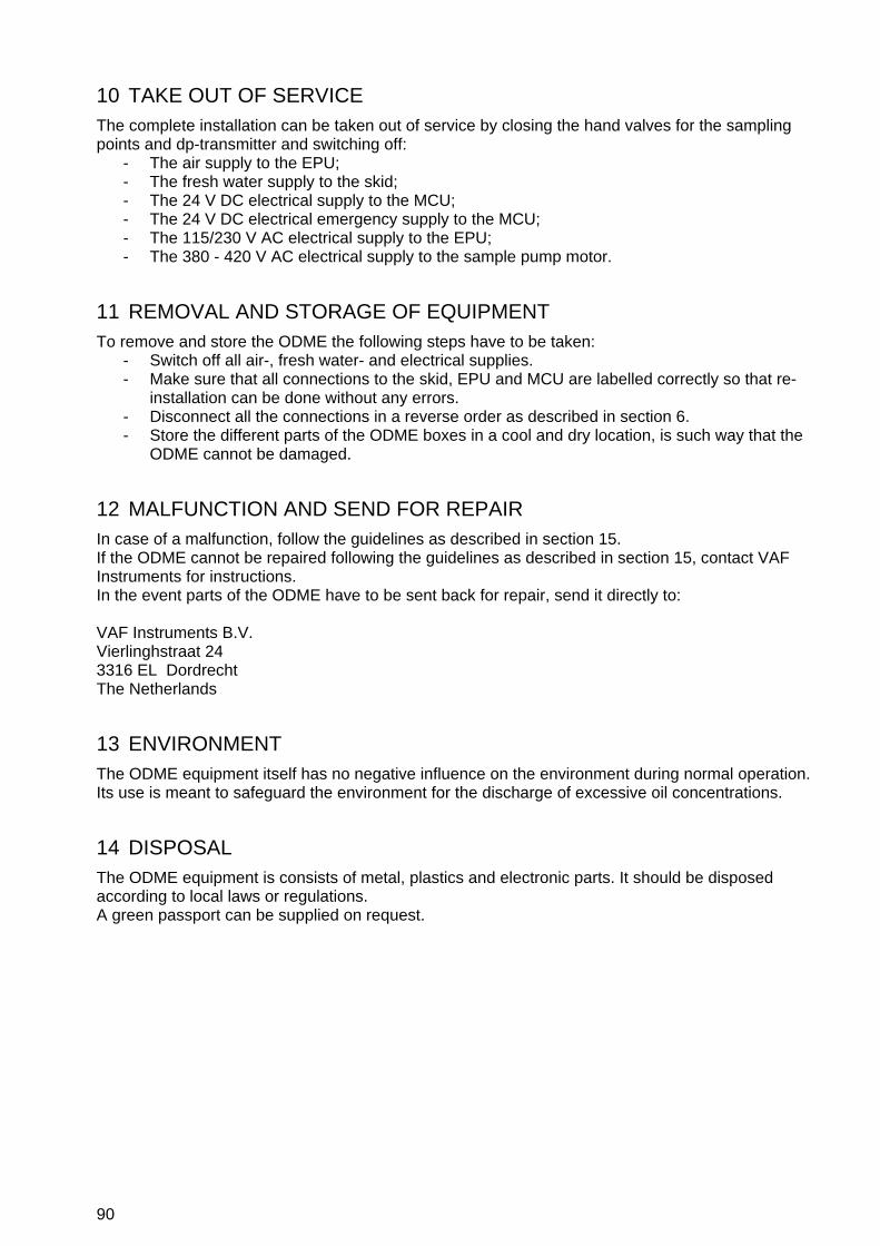
90
10 TAKE OUT OF SERVICE The complete installation can be taken out of service by closing the hand valves for the sampling points and dp-transmitter and switching off:
- The air supply to the EPU; - The fresh water supply to the skid; - The 24 V DC electrical supply to the MCU; - The 24 V DC electrical emergency supply to the MCU; - The 115/230 V AC electrical supply to the EPU; - The 380 - 420 V AC electrical supply to the sample pump motor.
11 REMOVAL AND STORAGE OF EQUIPMENT To remove and store the ODME the following steps have to be taken:
- Switch off all air-, fresh water- and electrical supplies. - Make sure that all connections to the skid, EPU and MCU are labelled correctly so that re-
installation can be done without any errors. - Disconnect all the connections in a reverse order as described in section 6. - Store the different parts of the ODME boxes in a cool and dry location, is such way that the
ODME cannot be damaged.
12 MALFUNCTION AND SEND FOR REPAIR In case of a malfunction, follow the guidelines as described in section 15. If the ODME cannot be repaired following the guidelines as described in section 15, contact VAF Instruments for instructions. In the event parts of the ODME have to be sent back for repair, send it directly to: VAF Instruments B.V. Vierlinghstraat 24 3316 EL Dordrecht The Netherlands
13 ENVIRONMENT The ODME equipment itself has no negative influence on the environment during normal operation. Its use is meant to safeguard the environment for the discharge of excessive oil concentrations.
14 DISPOSAL The ODME equipment is consists of metal, plastics and electronic parts. It should be disposed according to local laws or regulations. A green passport can be supplied on request.

91
15 TROUBLE SHOOTING AND FAULT FINDING
15.1 INTRODUCTION FAULT FINDING GUIDE
The first requirement when attempting to find a fault in the system, is to ensure that the monitor is correctly set up to run. A large number of service problems can be directly related to a simple mechanical fault, which appears to cause a large number of seemingly unrelated problems. It is essential to check before delving too deeply, that all hand-valves in the system are open; that the fresh water supply is available and clean and free of any contaminants; that the air supply to the EPU is on; that electrical supply to the pump is on; and that the electrical supply to the MCU and EPU is on. It is also important to note that most service problems are mechanical faults and not electronic faults. On the whole, electronic systems are much more reliable than the mechanical components connected to them. However, when a fault occurs, the tendency is to distrust the electronic systems and look for faults in the electronic parts, discounting the mechanical parts. This tendency should be reversed. The emphasis in this fault finding guide and the following “Repair” section is on mechanical repair and overhaul. Indications are given to assist in electronic repairs, but it is expected that most fault will be rectified by complete board replacement, rather than component replacement. Therefore, it is indicated which board is likely to be the source of the particular problem.
SAFETY PRECAUTIONS: MAKE SURE THAT ALL SAFETY REQUIREMENTS AS DESCRIBED IN SECTION 4.1 ARE MET BEFORE ANY WORK IS COMMENCED.
CAUTION: The printed circuit boards have CMOS components which may be damaged by electrostatic discharges. Observe correct procedures for handling CMOS components. It is also recommended to store the circuit boards in electrostatic proof cases.

92
15.2 FAULT FINDING GUIDE
The structure of the following fault finding guide is that the correct functioning path is on the left of the page; the section of the manual for the fault finding is indicated on the right of the page. To use the guide, start at the beginning and take the monitor through the outlined operating procedure, checking that the monitor operates correctly at each point. Should the monitor not operate as specified, refer to the right side of the page and turn to that section of the manual or refer directly to the fault as indicated on the MCU. If the fault cannot be rectified from this guide, please contact VAF Instruments to request specialist assistance. Refer to the serial number of the monitor and explain up to which section in this guide the monitor worked correctly. CORRECT FUNCTIONING PATH IF FAULTY 1 Turn the switch on the MCU to “Control Unit”.
The display of MCU will indicate “STANDBY”.
Refer to section 15.6
2 Press the SETUP key to enter the setup mode. Select during SETUP the appropriate sample point and oil type.
Refer to section 15.4
3 Press the FLUSH key to enter the FLUSH mode ...wait 7 minutes.
Refer to section 15.4
4 Air is supplied to the solenoid valves in the EPU solenoid V10 and the selected sample valve is energised.
Refer to section 15.8
5 The pneumatic shuttle valve on the skid assembly activates V10 together with the selected sample valve in the pump room are opened.
Refer to section 15.9
6 The lamp “Running” on the starter box lights up. The sample pump starts. The monitor is now in the BACKFLUSH MODE. Fresh water is being pumped from the fresh water inlet, through the sample pump, through the detector cell and via V11 discharged through the sample inlet port of the skid back to the sample probe selected.
Refer to section 15.11.1 Refer to section 15.11.2
7 After approximately 2 minutes the FORWARD FLUSH mode is entered and a window wash is performed for 12 s.
Refer to section 15.4
8 In the EPU solenoid V11 is energised and solenoid V12 is energised for 12 s.
Refer to section 15.8
9 The window wash pump on the skid assembly operates for a few strokes.
Refer to section 15.10
10 The pneumatic valve V11 on the skid assembly is now open. The monitor is now in the FORWARD FLUSH MODE. Clean water is pumped from the fresh water inlet through the sample pump, detector cell and then discharge through the sample outlet port into the slop tank/discharge line.
Refer to section 15.9

93
11 The No Flow alarm is now enabled. Any problem with the fresh water supply will be highlighted at this point.
Refer to section 15.11.1.2
12 At this point the calibration is checked. Since the monitor is operating on fresh water, the ZERO ERROR alarm will be activated, if there is any contamination.
Refer to section 15.3.1
13 If the windows in the detector cell on the skid assembly are dirty the “PATH DIRTY” alarm will be activated.
Refer to section 15.3.2
14 At the end of the flush cycle the sample pump will stop and V10 is released. The display of the MCU will indicate “MODE IDLE”.
Refer to section 15.4
15 In the EPU all the solenoids including the selected sample point are deactivated. The green lamp “Running” on the Starter Box will turn off and the sample pump will stop.
Refer to section 15.8
16 All the pneumatic valves in the system are now in their de-energised position. The system is now in IDLE mode. If required a self test can be performed at this point. This can be done by pressing the SELFTEST key. During the self test the display should indicate 500 ppm, the audio alarm should sound.
Refer to section 15.9
17 To select the SAMPLE mode press the “Sample” key. The display of the MCU will indicate “MODE SAMPLE”. The green lamp “Running” on the starter box will come on. Solenoid V11 and the selected sample valve are energised. The sample pump starts running again.
Refer to section 15.11
18 The monitor is now in sample mode and no alarms are activated.
Refer to section 15.4
19 After 3 minutes the window wash pump will operate for 3 seconds. The window wash solenoid V12 in the EPU is activated. This action is repeated every 3 minutes.
Refer to section 15.10

94
15.3 CALIBRATION ALARMS
15.3.1 Zero error alarm
Probable causes: 1 Sample pump cavitating. - Check the pressure gauge settings on the Skid
Assembly. For correct settings see section 15.11.2
2 Flushing water contaminated. - Check flushing water for oil, dirt or of it contains air.
- Check the fresh water tank, if installed. - Drain the fresh water tank and refill the tank, if
necessary.
3 Excessive oil left in monitor. - Check the sample outlet of the monitor. Flush the monitor again till the “Zero Error” alarms clears.It is advisable to let the monitor complete the flush cycle each time. This will give the maximum amount of flushing.
4 Transmitter error. - Check the cables from the measurement cell to the
junction box on the skid. - Check the cables from the junction box on the skid to the
EPU terminal strip.
If the alarm persists it is likely that the cell is faulty and will require replacement.
NOTE: See section 9.1 for the replacement of the measurement cell assembly.

95
15.3.2 Path dirty alarm
Probable causes: 1 Windows of detector cell dirty. - Operate the window wash pump a few times by pressing
[WINDOW WASH] during the flush cycle. This should clean the windows sufficiently to cancel the alarm.
If the alarm persists it is necessary to clean the windows in the measurement cell manually as described in section 9.1.
2 Excessive oil in detector cell, “Zero Error” alarm also activated.
- Check the sample outlet of the monitor. - Flush the monitor again till the “Zero Error” alarms clears.
It is advisable to let the monitor complete the flush cycle each time. This will give the maximum amount of flushing.
3 Transmitter error. - Check the cables from the measurement cell to the
junction box on the skid. - Check the cables from the junction box on skid to the EPU
terminal strip.
If the alarm persists, then it is likely that the cell is faulty and will require replacement.
- Also consult section 15.4.5

96
15.4 SYSTEM ALARMS
15.4.1 No air
Consult section 15.7 and 15.8
15.4.2 No flow
Consult section 15.11.2
15.4.3 Power failures
Consult section 15.6
15.4.4 Communication failure
Probable causes: 1 Communication link not correct. - Check the power to the EPU.
- Check the communication link between the MCU and EPU.- Check with a voltmeter on connector X9, terminal 1, 2, 3
and 4 in MCU or connector X1, terminal 5, 6, 8 and 9 in EPU for data transmission.
- Term.1/2 or 5/6 for data transmission from MCU - Term.3/4 or 8/9 for data transmission from EPU
If the alarm is persistent, please contact VAF Instruments
15.4.5 Led feedback error
Probable causes: 1 Transmitter error. - Check the cables from the measurement cell to the
junction box on the skid. - Check the cables from the junction box on skid to the EPU
terminal strip.
If the alarm persists, it is likely that the cell is faulty and will require replacement.
NOTE: See section 9.1 for the replacement of the measurement cell assembly.
15.4.6 Flow overrange failure
Probable causes: 1 Overboard discharge flowrate to
high.
- Check the overboard discharge flowrate and reduce if necessary.
2 Flowmeter not functioning correct.
- Check the connections of the related flowmeter. - Check the calibration of the related flowmeter.
Also consult section 15.12

97
15.4.7 Flow underrange failure
Probable causes: 1 Flowmeter not functioning
correct.
- Check the connections of the related flowmeter. - Check the calibration of the related flowmeter.
Also consult section 15.12
15.4.8 Overboard arrangement failure
Probable causes: 1 No power supply.
- Check the power supply to the overboard valve actuator. - Check the signal connections between the MCU and the
valve actuator. - No air supply. - Check the air supply to the overboard valve actuator. - Check the signal connections between the MCU and the
valve actuator.
2 No air supply.
- Check the air supply to the overboard valve actuator. - Check the signal connections between the MCU and the
valve actuator. - Feedback switch failure. - Check the functioning of the feedback switch. - Check the connections between the MCU and the
feedback switch.
3 Feedback switch failure.
- Check the functioning of the feedback switch. - Check the connections between the MCU and the
feedback switch. - Overboard valve failure. - Check functioning of the overboard valve.
4 Overboard valve failure.
- Check functioning of the overboard valve.
15.4.9 Discharge rate failure
Probable causes: 1 Discharge rate to high. - Check the overboard discharge rate and reduce it to clear
the alarm. Also consult section 7.5
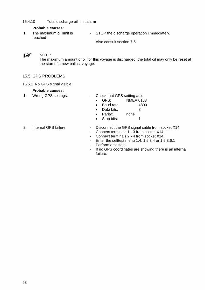
98
15.4.10 Total discharge oil limit alarm
Probable causes: 1 The maximum oil limit is
reached - STOP the discharge operation i mmediately.
Also consult section 7.5
NOTE: The maximum amount of oil for this voyage is discharged. the total oil may only be reset at the start of a new ballast voyage.
15.5 GPS PROBLEMS
15.5.1 No GPS signal visible
Probable causes: 1 Wrong GPS settings.
- Check that GPS setting are:
GPS: NMEA 0183 Baud rate: 4800 Data bits: 8 Parity: none Stop bits: 1
2 Internal GPS failure - Disconnect the GPS signal cable from socket X14.
- Connect terminals 1 - 3 from socket X14. - Connect terminals 2 - 4 from socket X14. - Enter the selftest menu 1.4, 1.5.3.4 or 1.5.3.6.1 - Perform a selftest. - If no GPS coordinates are showing there is an internal
failure.
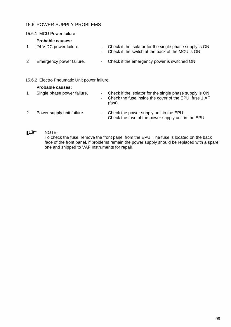
99
15.6 POWER SUPPLY PROBLEMS
15.6.1 MCU Power failure
Probable causes: 1 24 V DC power failure.
- Check if the isolator for the single phase supply is ON. - Check if the switch at the back of the MCU is ON.
2 Emergency power failure.
- Check if the emergency power is switched ON.
15.6.2 Electro Pneumatic Unit power failure
Probable causes: 1 Single phase power failure.
- Check if the isolator for the single phase supply is ON. - Check the fuse inside the cover of the EPU, fuse 1 AF
(fast).
2 Power supply unit failure. - Check the power supply unit in the EPU. - Check the fuse of the power supply unit in the EPU.
NOTE: To check the fuse, remove the front panel from the EPU. The fuse is located on the back face of the front panel. if problems remain the power supply should be replaced with a spare one and shipped to VAF Instruments for repair.

100
15.7 AIR SUPPLY PROBLEMS
15.7.1 Air supply failure
Probable causes: 1 No air supply.
- Check the air supply to the EPU, normally set to 4.0 bar
(0.4 MPa). - Check the ship’s control air supply. - Check all connections for leakage.
2 Pressure sensor failure. - Check the connections to the pressure sensor on the
solenoid valve block on the EPU assembly. - Check the functioning of the pressure sensor with a digital
voltmeter for open/closed circuit function.
15.7.2 Water found in the monitors of the air system
Probable causes: 1 Water in air supply unit housing. - Check the air supply unit regulator and drain if necessary.
If a great deal of water is found the filters in the regulators need to be replaced.
2 Malfunction in ship’s control air
system. - Check the ship’s compressors. - Check the ship’s air dryers.
15.8 SOLENOID VALVE PROBLEMS
15.8.1 Valve not working
Probable causes: 1 No air supply.
- Check the air supply unit regulator, normally set to 4.0 bar
(0.4 MPa). - Check the ship’s control air supply. - Check all connections for leakage.
2 24 V power supply failure. - Check the 24 V power supply.
- Check the fuse of the power supply. - Check the connections to the solenoid valve.
3 Solenoid valve actuator not
functioning. - Check the solenoid valve connections. - Change the plug on the faulty solenoid, for the plug from a
solenoid that is known to be working. Replace if necessary.
4 Solenoid air valve not working. - Check the air valve for dirt, water or other contamination. Replace if necessary.
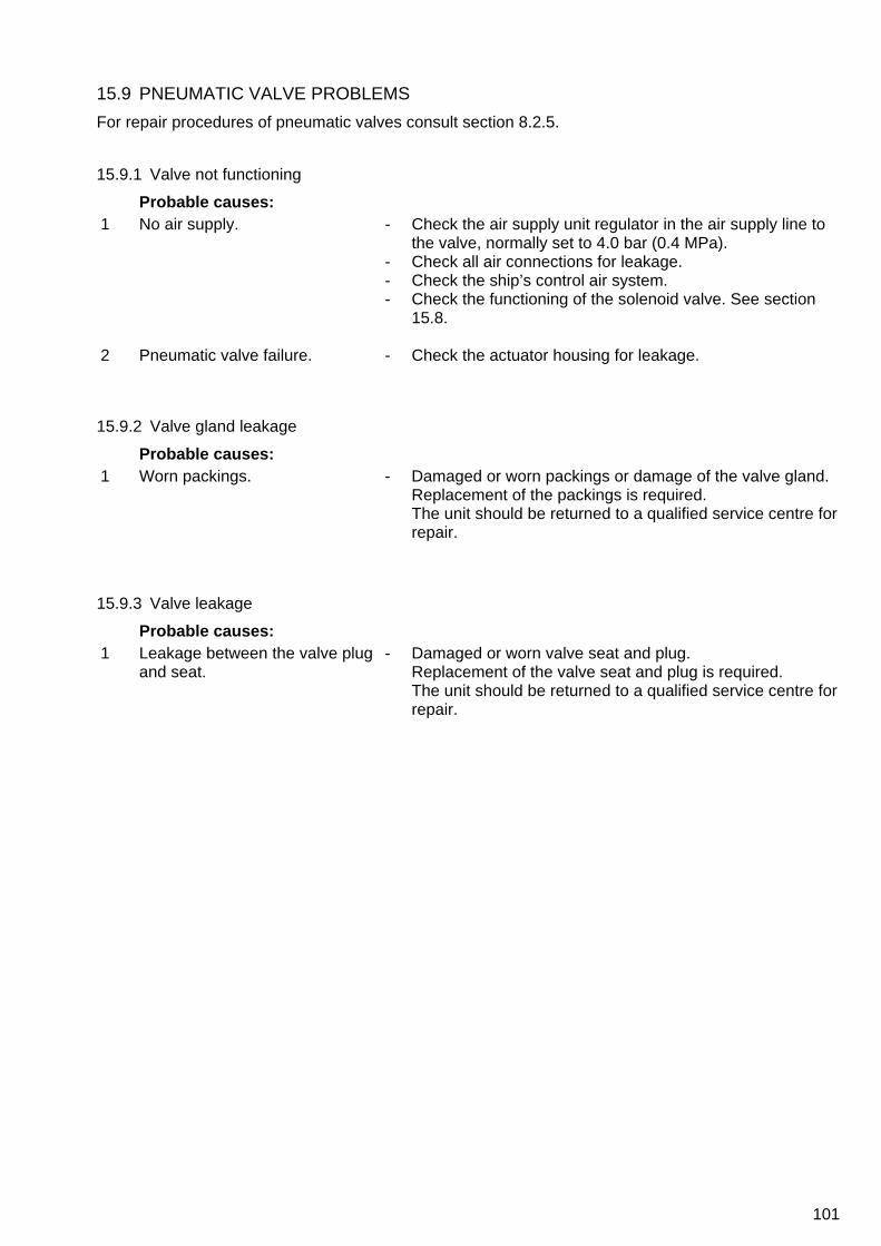
101
15.9 PNEUMATIC VALVE PROBLEMS
For repair procedures of pneumatic valves consult section 8.2.5.
15.9.1 Valve not functioning
Probable causes: 1 No air supply. - Check the air supply unit regulator in the air supply line to
the valve, normally set to 4.0 bar (0.4 MPa). - Check all air connections for leakage. - Check the ship’s control air system. - Check the functioning of the solenoid valve. See section
15.8.
2 Pneumatic valve failure. - Check the actuator housing for leakage.
15.9.2 Valve gland leakage
Probable causes: 1 Worn packings. - Damaged or worn packings or damage of the valve gland.
Replacement of the packings is required. The unit should be returned to a qualified service centre for repair.
15.9.3 Valve leakage
Probable causes: 1 Leakage between the valve plug
and seat. - Damaged or worn valve seat and plug.
Replacement of the valve seat and plug is required. The unit should be returned to a qualified service centre for repair.

102
15.10 WINDOW WASH PUMP PROBLEMS
For disassembly and re-assembly procedures of the window wash pump consult section 8.2.4.
15.10.1 Pump does not work
Probable causes: 1 Air supply failure.
- Check the air supply to solenoid V12 in the EPU, minimum
5.0 bar (0.5 MPa). - Check the air supply to the regulator/lubricator, minimum
5.0 bar (0.5 MPa). - Check the functioning of solenoid V12 in the EPU.
2 Air cycle valve failure. - Check the sleeve and cycling spool (under the cap of the
muffler) for contamination. Replace if necessary.
3 Electric circuit failure. - Check the power supply in the EPU. - Check the connection to solenoid V12 in the EPU. - Check the operation of solenoid V12.
Replace if necessary. - Check the connection between the MCU and the EPU.
15.10.2 Pump cycles without pumping or does not stall
Probable causes: 1 No water supply. - Check the water supply to the pump.
2 Check valves not seating or
leaking in the system. - Inspect the inlet check valve. - Inspect the outlet check valve.
15.10.3 False cycle
Probable causes: 1 Leakage from the pilot exhaust
(top centre of the cap).
- Check the air section seal. Replace if necessary.
15.10.4 Fluid appears at muffler
Probable causes: 1 High pressure seal leakage.
- Check the high pressure seal.
Replace if necessary.

103
15.11 SAMPLE PUMP PROBLEMS
15.11.1 Electrical problems
15.11.1.1 Pump runs but the green indicator on the starter box is off Probable causes: 1 Indicator failure.
- Check power supply to indicator lamp. - Check indicator lamp.
15.11.1.2 Pump should be running but is off Probable causes: 1 3-phase power supply failure. - Check if the 3-phase power supply is switched on.
- Check the fuses of the 3-phase power supply. the water supply to the pump.
2 Thermal trip of the pump. - Check the terminal trip on the pump contactor in the starter box. The red light is ON. Reset if necessary.
3 Pump contactor failure. - Check the power on the contactor terminals (1,2), these should be 24 V DC. Also check also for correct polarity.
- Check the 24 V DC power supply in the EPU. - Check the connections between the starter box and the
EPU.
NOTE: If the motor repeatedly trips out on thermal trip, check the motor and pump for binding or blockages etc. do not force the motor to run.
15.11.2 Pump related problems
NOTE: During forward flush and in sample mode, normal operating conditions are: - Pump discharge pressure 5 to 8 bar. (0.5 to 0.8 MPa). - Pump suction pressure 0 to 1 bar. (0 to 0.1 MPa). (Pressures may vary from one installation to another).

104
15.11.2.1 No flow Probable causes: 1 No fresh water supply.
(low discharge pressure < 2 bar during flushing). (< 0.2 MPa during flushing).
- Check if the 3-phase power supply is switched on. - Check the fuses of the 3-phase power supply. the water
supply to the pump.
2 No sample water supply. (low discharge pressure < 2 bar during sampling). (< 0.2 MPa during sampling).
- Check if the cargo/stripping pump is ON. - Check if the discharge line is filled with water. - Check if the manual valve of the sample probe is open. - Check if the pneumatic valve in the sample line is open. - Check if the manual valve in the sample inlet of the skid
assembly is open.
3 Blockage in outlet line. (high discharge pressure > 10 bar). (>1 MPa).
- Check if the manual valve in the sample outlet of the skid assembly is open.
- Check if the manual valve on the discharge to the slop tank is open.
4 Flowrate through the monitor too low
- Check the flowrate through the monitor. - Read the skid flow from the display during FORWARD
FLUSH or SMAPLE mode and ensure the flow is between 450 - 550 l/h.
- The flowrate can be adjusted by means of the needle valve on the outlet of measurement cell.
5 Malfunction of the flow sensor. - Check the electrical connections on the flow sensor. - Check the connections between the flow sensor and the
EPU. - Check the function of the flow sensor.
NOTE: During commissioning the flowrate through the monitor is set to between 450 and 550 l/hour. The “no-flow” alarm is activated at flows less than 240 litres per hour.
NOTE: During back flush, the “no flow” alarm is inhibited. The flow alarm comes into operation at the start of the forward flush cycle.

105
15.12 DIFFERENTIAL PRESSURE TRANSMITTER PROBLEMS
NOTE: For disassemble and re-assemble instructions consult section 8.2.7.
15.12.1 No line current
Probable causes: 1 Transmitter connections. - Check the wiring polarity and continuity.
- Check for shorts or ground loops. - Check if the power supply connector is connected to the
main board.
2 Power supply. - Check the power supply output. The voltage must be between 12 and 45 V DC at the transmitter terminals.
3 Electronic circuit failure. - Check the main board for defects by replacing it with a spare one.
15.12.2 Current of 21.0 mA or 3.9 mA
Probable causes: 1 Pressure tap (piping). - Verify if the blocking valves are fully open.
- Check for gas in the liquid lines. - Check the specific density of the process fluid. - Check the process flanges for sediments. - Check the pressure connection. - Check if the bypass valve is closed. - Check if the pressure applied is not over the upper limit of
the DPT range.
2 Sensor to the main circuit connection.
- Check all connections (male and female connectors).
3 Electronic circuit failure. - Check the sensor circuit for defects by replacing it with a spare one. Replace if necessary.
106
15.12.3 Incorrect output
Probable causes: 1 Transmitter connections.
- Check the power supply voltage - Check for intermittent short circuits, open circuits and
grounding problems.
2 Noise measurement fluid. - Adjust damping.
3 Pressure tap. - Check for gas in the liquid lines. - Check the integrity of the circuit by replacing it with a spare
one.
4 Calibration. - Check the calibration of the dP transmitter.
15.13 FAULT FINDING FORM
In case the fault finding guide does not result in a proper working of the system, the fault finding form can be used. This form should be filled in and returned to VAF Instruments Service department. The form is included in this technical manual 641.

107
OIL DISCHARGE MONITOIRNG & CONTROL SYSTEM
FAULT FINDING FORM
Fault Finding Aid Checklist Oilcon® Mark 6M Serial number MCU: ………………… (the serial number can be found on the backside, 6 digits) Serial number EPU: ………………… (Stamped on the Ex ia type plate at the left side of the EPU, 6 digits) At the DATA ENTRY PARAMETERS printout you will find the K-Factor parameters: Skid K-Factor: …………………p/l Cell K-Factor: ………………… The following steps have to be followed in order for VAF Instruments to determine if the ODM system is having a malfunction. If during the complete procedure an alarm is triggered, push the Alarm rest button and write down the Alarm.
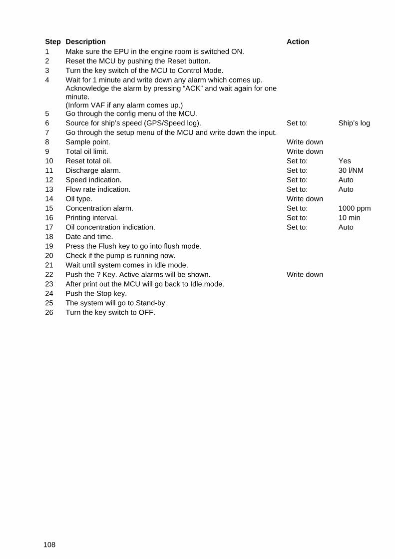
108
Step Description Action 1 Make sure the EPU in the engine room is switched ON. 2 Reset the MCU by pushing the Reset button. 3 Turn the key switch of the MCU to Control Mode. 4 Wait for 1 minute and write down any alarm which comes up.
Acknowledge the alarm by pressing “ACK” and wait again for one minute. (Inform VAF if any alarm comes up.)
5 Go through the config menu of the MCU. 6 Source for ship’s speed (GPS/Speed log). Set to: Ship’s log 7 Go through the setup menu of the MCU and write down the input. 8 Sample point. Write down 9 Total oil limit. Write down 10 Reset total oil. Set to: Yes 11 Discharge alarm. Set to: 30 l/NM 12 Speed indication. Set to: Auto 13 Flow rate indication. Set to: Auto 14 Oil type. Write down 15 Concentration alarm. Set to: 1000 ppm 16 Printing interval. Set to: 10 min 17 Oil concentration indication. Set to: Auto 18 Date and time. 19 Press the Flush key to go into flush mode. 20 Check if the pump is running now. 21 Wait until system comes in Idle mode. 22 Push the ? Key. Active alarms will be shown. Write down 23 After print out the MCU will go back to Idle mode. 24 Push the Stop key. 25 The system will go to Stand-by. 26 Turn the key switch to OFF.
109
List of alarms which were triggered during the above procedure:
: ………………………………………………………………
: ………………………………………………………………
: ………………………………………………………………
: ………………………………………………………………
: ………………………………………………………………
: ………………………………………………………………
: ………………………………………………………………
: ………………………………………………………………
VAF Instruments B.V. Vierlinghstraat 24 3316 EL Dordrecht P.O. Box 40 3300 AA Dordrecht The Netherlands Tel.: +31 (0)78 6183100 Fax: +31 (0)78 6177068 Website: www.vaf.nl E-mail: [email protected]

110
16 CERTIFICATES OF CONFORMITY AND CERTIFICATES OF APPROVAL
16.1 CERTIFICATES OF CONFORMITY
Certificate: Type: For:
Det Norske Veritas EC type examination certificate Oil Discharge system OILCON Mark 6M
KEMA EC type examination certificate Interface and Detector cell
KEMA EC declaration of conformity Oilcon® Oil Discharge Monitoring and Control System Oilcon Mark 6M
IEC IECEx certificate of conformity Oil Discharge Monitor type Oilcon Mark 6M
PTB EC type examination certificate Inductive sensor (skid flowmeter)
KEMA EC type examination certificate dP transmitter (overboard discharge flowmeter)

111

112

113
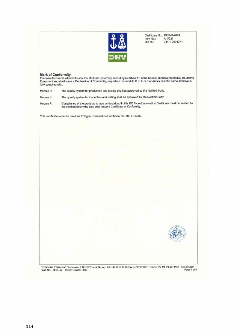
114
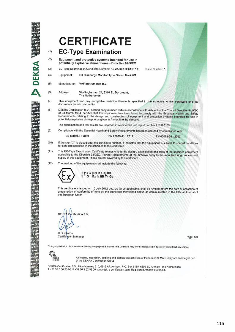
115

116

117

118

119
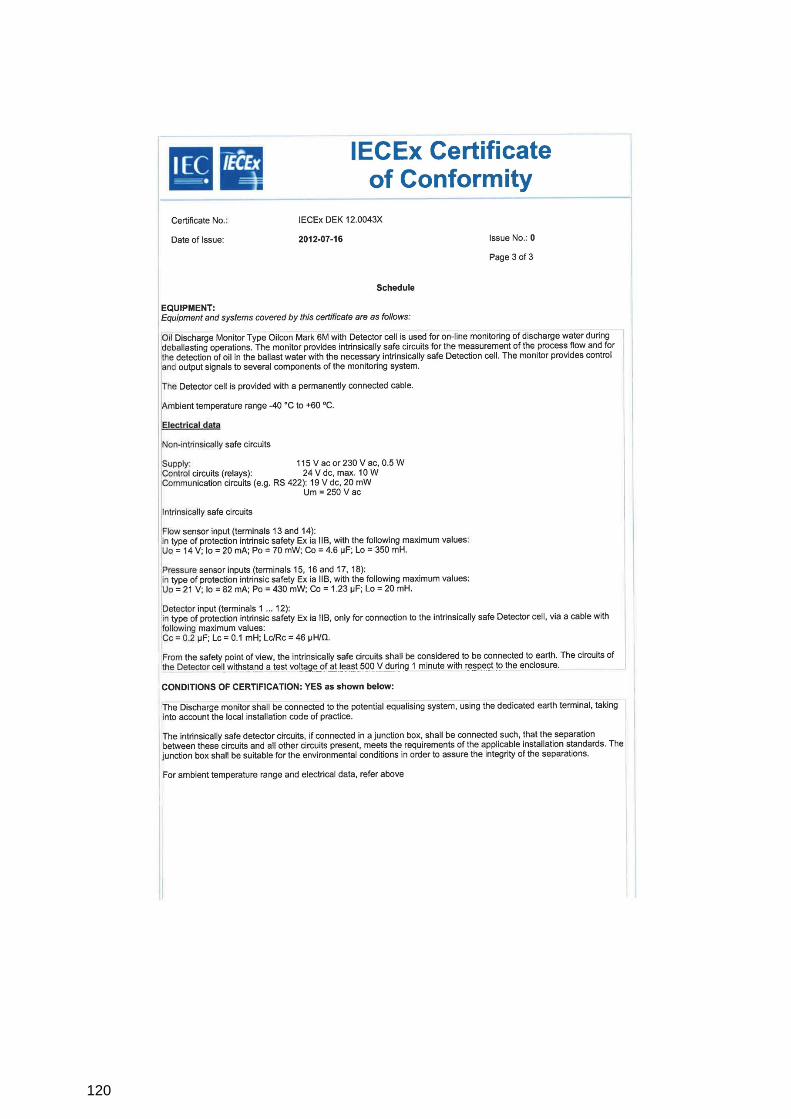
120

121

122

123
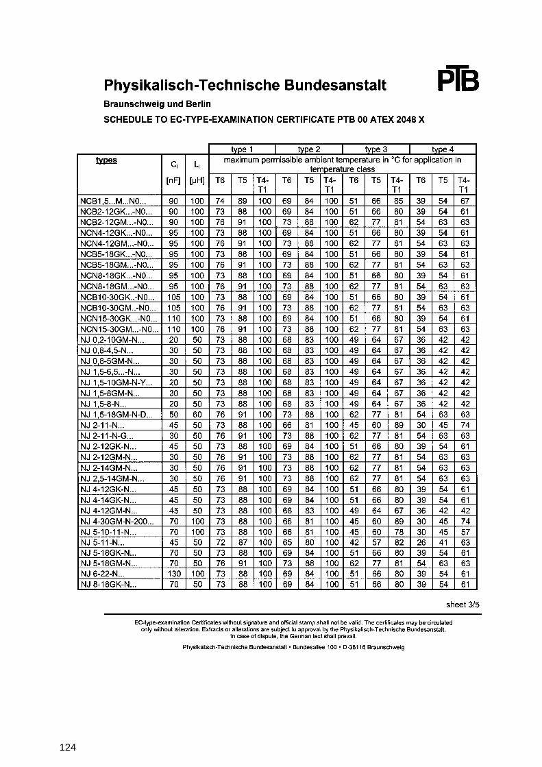
124

125

126

127

128

129
16.2 CERTIFICATES OF APPROVAL
ABS Certificate of Design
Assessment Oilcon® Oil Discharge
Monitoring and Control System Oilcon Mark 6M
ABS Certificate of Manufacturing
Assessment Oilcon® Oil Discharge
Monitoring and Control System Oilcon Mark 6M
ABS Certificate of Type Approval Oilcon® Oil Discharge
Monitoring and Control System Oilcon Mark 6M
CCS Certificate of Type Approval Oilcon® Oil Discharge
Monitoring and Control System Oilcon Mark 6M
NKK Certificate of Type Approval Oilcon® Oil Discharge
Monitoring and Control System Oilcon Mark 6M
RMRS (Russian Maritime Register of Shipping)
Certificate of Type Approval Oilcon® Oil Discharge Monitoring and Control System Oilcon Mark 6M
USCG (United States Coast Guard)
Certificate of Type Approval Oilcon® Oil Discharge Monitoring and Control System Oilcon Mark 6M
KR (Korean Register)
Certificate of Type Approval Oilcon® Oil Discharge Monitoring and Control System Oilcon Mark 6M
Canada Certificate of Type Approval Oilcon® Oil Discharge
Monitoring and Control System Oilcon Mark 6M
NOTE: MOST RECENT COPIES OF ABOVE MENTIONED CERTIFICATES OF APPROVAL ARE AVAILABLE ON OUR WEB-SITE WWW.VAF.NL

130
17 DRAWINGS Description: Drawing number: Control drawing for Mark 6M Oil Discharge Monitor 0806-0005 Dimensional drawing ball valve flowmeter kit Ballast Monitor 0806-1041 Dimensional drawing motor starter box Ballast Monitor Mark 6 0806-1075 Dimensional drawing sample pump/motor Ballast Monitor Mark 6 0806-1076 Dimensional drawing sample valve Mark 6 0806-1077 Assembly drawing sample pump Ballast Monitor Mark 6 0806-1260 Part list sampling probe pipe connection Ø15 mm Ballast Monitor Mark 6M 0806-1265 Part list motor starter box Ballast Monitor Mark 6 0806-1267 Part list isolating valve Ø15 Ballast Monitor Mark 6 0806-1268 Part list detector cell Mark 6 0806-1279 Dimensional drawing MCU Mark 6M 0806-1285 Basic spare parts kit Ballast Monitor Mark 6M 0806-1286 Dimensional drawing and parts list EPU 1-2 sample valves Mark 6M 0806-1287 Dimensional drawing and parts list ballast skid Mark 6M 0806-1288 Grab cock and injection point Ballast Monitor Mark 6 0806-1621 Light scatter cell Ballast Monitor Mark 6 0806-1622 Connection diagram motor starter box Mark 6 0806-2032 Electrical connection diagram Ballast Monitor Mark 6M MEPC 108(49) 0806-2048 Connection diagram Oilcon Mark 6 Cable spec. MEPC 108(49) 0806-2050 Schematic diagram overboard valve control Ballast Monitor Mark 5/6 0806-5019 Schematic diagram Oilcon Ballast Monitor Mark 6M 0806-5026 Installation flowmeter Ballast Monitor Mark 5/6 0806-8016 Installation requirements fresh water supply line Ballast Monitor Mark 5/6 0806-8023 Schematic pipe arrangement skid Mark 6 0806-8039 Cable termination instruction Ballast Monitor Mark 6 0806-8040 Schematic installation diagram Oilcon Monitor System with 1x dP/I transmitter Mark 6
0806-8068
Bulkhead penetration and piping diagram Mark 6M 0806-8069 Multi cable transit Ballast Monitor Mark 6 0806-8070 Connection diagram dP/I transmitter type Fuji 0810-2010 Assembly drawing window wash pump Mark 6 0871-1212 Dimensional drawing dP/I transmitter FUJI flowmeter kit Ballast Monitor Mark 5/6
0899-1092
Parts list FUJI dP/I transmitter flowmeter kit Mark 5/6 0899-1249 Parts list FUJI pressure reducing valve fresh water connection ½" BSPT Ballast Monitor Mark 6
0899-1256
Parts list air supply units Ballast Monitor Mark 6 0899-1258

131
Drawing 1, 0806-0005 sheet 1
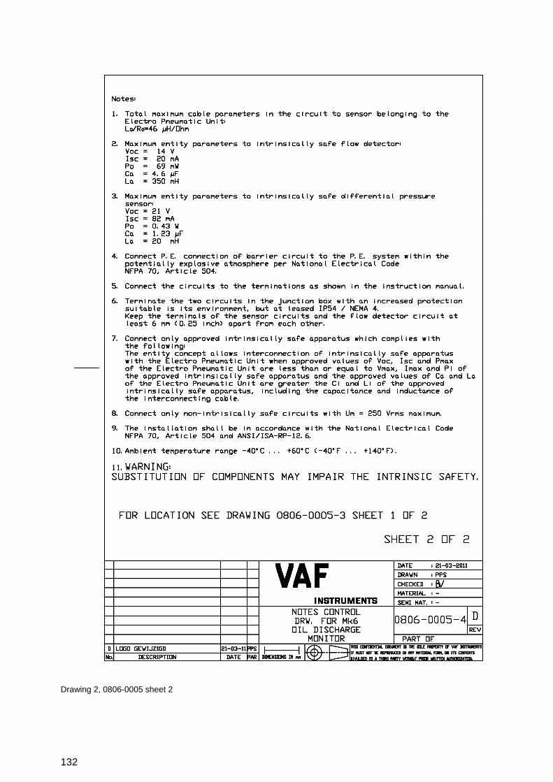
132
Drawing 2, 0806-0005 sheet 2

133
Drawing 3, 0806-1041

134
Drawing 4, 0806-1075

135
Drawing 5, 0806-1076

136
Drawing 6, 0806-1077
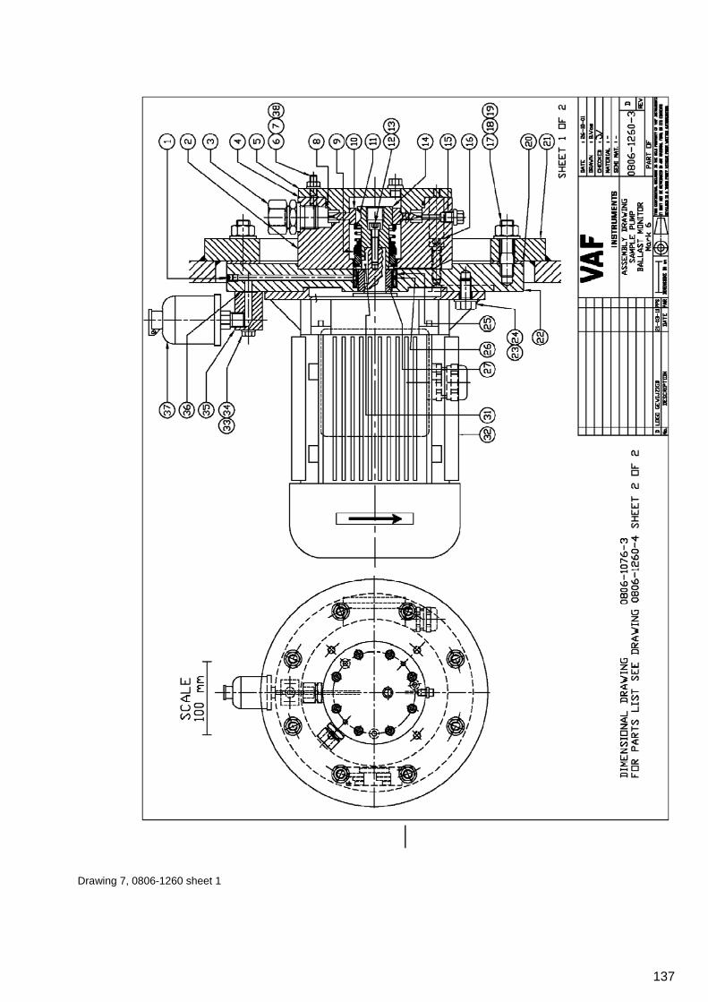
137
Drawing 7, 0806-1260 sheet 1

138
Drawing 8, 0806-1260 sheet 2

139
Drawing 9, 0806-1265

140
Drawing 10, 0806-1267

141
Drawing 11, 0806-1268

142
Drawing 12, 0806-1279

143
Drawing 13, 0806-1285

144
Drawing 14, 0806-1286

145
Drawing 15, 0806-1287

146
Drawing 16, 0806-1288

147
Drawing 17, 0806-1621

148
Drawing 18, 0806-1622

149
Drawing 19, 0806-2032
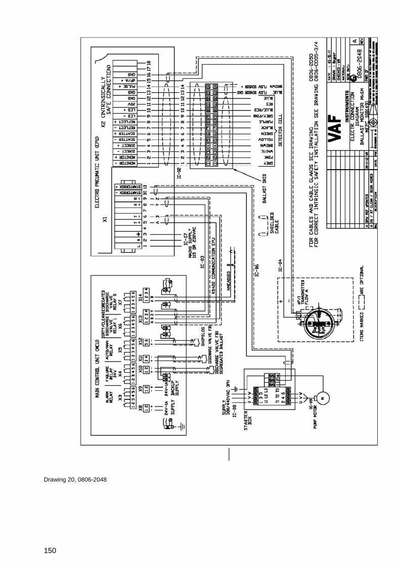
150
Drawing 20, 0806-2048

151
Drawing 21, 0806-2050

152
Drawing 22, 0806-5019

153
Drawing 23, 0806-5026

154
Drawing 24, 0806-8016

155
Drawing 25, 0806-8023
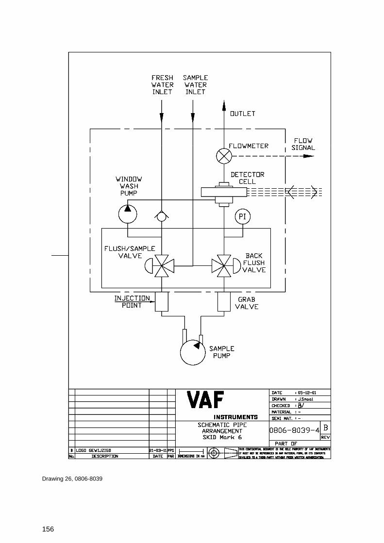
156
Drawing 26, 0806-8039

157
Drawing 27, 0806-8040
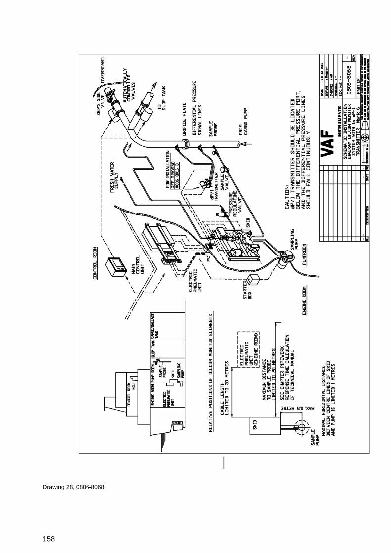
158
Drawing 28, 0806-8068

159
Drawing 29, 0806-8069 sheet 1

160
Drawing 30, 0806-8069 sheet 2

161
Drawing 31, 0806-8069 sheet 3

162
Drawing 32, 0806-8070

163
Drawing 33, 0810-2010
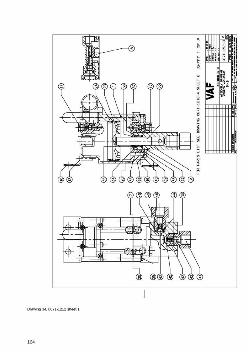
164
Drawing 34, 0871-1212 sheet 1

165
Drawing 35, 0871-1212 sheet 1
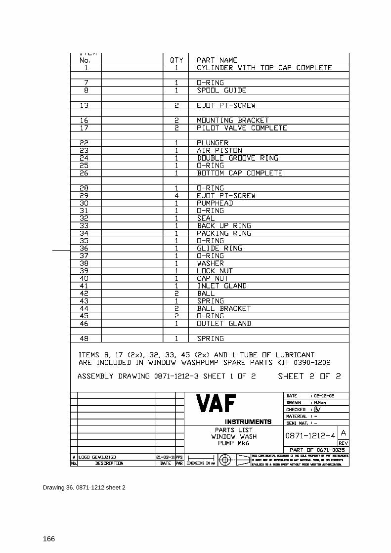
166
Drawing 36, 0871-1212 sheet 2

167
Drawing 37, 0899-1092

168
Drawing 38, 0899-1249

169
Drawing 39, 0899-1256

170
Drawing 40, 0899-1258

171
18 ABBREVIATIONS ATF Automatic Transmission Fluid DPT Differential Pressure Transmitter EPU Electro Pneumatic Unit GPS Global Position System IMO International Maritime Organization IOM Installation, Operation and Maintenance MCU Main Control Unit NO Normally Open NC Normally Closed

172
19 SPARE PARTS
19.1 STANDARD SPARES
Standard spare parts supplied with every Oilcon® Oil Discharge Monitoring and Control System delivery: Description Stock number Quantity
Standard spare parts OIL DISCHARGE MONITOR system 0390-1301 O-ring I.D. 53.70 x 1.78 mm 2 Bulkhead seal lubricant 500ml Cleansing brush 1 Slow fuse 630 mA slow 2
19.2 SERVICING SPARES
When ordering spares, always refer to the Oilcon® Oil Discharge Monitoring and Control System’s serial number and list required spares indicating:
- Stock number; - Quantity required; - Description of kit.
The following spare parts are recommended to be kept on stock: Description Stock number Quantity
Sample pump – Impeller replacement kit 0390-1210 (See drawing 0806-1260) comprising: Impeller (10) 1 Sample pump maintenance kit (0390-1182): Mechanical seal (9) 1 O-ring (8) 1 O-ring (13) 1 Oil sealing (25) 2 Shim (set) (4) 1

173
Description Stock number Quantity
Sample pump electric motor kit 0390-1209 (See drawing 0806-1260) Electric motor (32) 1 Key (31) 1 Bushing (27) 1
Window wash maintenance kit 0390-1202 (See drawing 0871-1212) Pilot valve complete (17) 2 Back up ring (33) 1 O-ring (45) 2
Electrical items spares kit 0390-1211 LED Green (starter box) 2 LED Red (starter box) 2 Fuses 500 mA slow (EPU) 2 Fuses 630 mA slow (EPU) 2

174
20 WARRANTY CONDITIONS 1. Without prejudice to the restrictions stated hereinafter, the contractor guarantees both the
soundness of the product delivered by him and the quality of the material used and/or delivered for it, insofar as this concerns faults in the product delivered which do not become apparent during inspection or transfer test, which the principal shall demonstrate to have arisen within 12 months from delivery in accordance with sub article 1A exclusively or predominantly as a direct consequence of unsoundness of the construction used by the contractor or as a consequence of faulty finishing or the use of poor materials.
1A. The product shall be deemed to have been delivered when it is ready for inspection (if
inspection at the premises of the contractor has been agreed) and otherwise when it is ready for shipment.
2. Articles 1 and 1A shall equally apply to faults which do not become apparent during inspection or
transfer test which are caused exclusively or predominantly by unsound assembly/installation by the contractor. If assembly/installation is carried out by the contractor, the guarantee period intended in article 1 shall last 12 months from the day on which assembly/installation is completed by the contractor, with the understanding that in this case the guarantee period shall end not later than 18 months after delivery in accordance with the terms of sub article 1A.
3. Defects covered by the guarantee intended under articles 1, 1A and 2 shall be remedied by the
contractor by repair or replacement of the faulty component either on or off the premises of the contractor, or by shipment of a replacement component, this remaining at the discretion of the contractor. Sub article 3A shall equally apply if repair or replacement takes place at the site where the product has been assembled/installed. All costs accruing above the single obligation described in the first sentence, such as are not restricted to shipment costs, travelling and accommodation costs or disassembly or assembly costs insofar as they are not covered by the agreement, shall be paid by the principal.
3A. If repair or replacement takes place at the site where the product has been assembled/installed,
the principal shall ensure, at his own expense and risk, that: a. the employees of the contractor shall be able to commence their work as soon as they have
arrived at the erection site and continue to do so during normal working hours, and moreover, if the contractor deems it necessary, outside the normal working hours, with the proviso that the contractor informs the principal of this in good time;
b. suitable accommodation and/or all facilities required in accordance with government regulations, the agreement and common usage, shall be available for the employees of the contractor;
c. the access roads to the erection site shall be suitable for the transport required; d. the allocated site shall be suitable for storage and assembly; the necessary lockable
storage sites for materials, tools and other goods shall be available; e. the necessary and usual auxiliary workmen, auxiliary machines, auxiliary tools, materials
and working materials (including process liquids, oils and greases, cleaning and other minor materials, gas, water, electricity, steam, compressed air, heating, lighting, etc.) and the measurement and testing equipment usual for in the business operations of the principal, shall be available at the correct place and at the disposal of the contractor at the correct time and without charge;
f. all necessary safety and precautionary measures shall have been taken and adhered to, and all measures shall have been taken and adhered to necessary to observe the applicable government regulations in the context of assembly/installation;
g. the products shipped shall be available at the correct site at the commencement of and during assembly.

175
4. Defects not covered by the guarantee are those which occur partially or wholly as a result of: a. non-observance of the operation and maintenance instructions or other than foreseeable
normal usage; b. normal wear and tear; c. assembly/installation by third parties, including the principal; d. the application of any government regulation regarding the nature or quality of the material
used; e. materials or goods used in consultation with the principal; f. materials or goods provided by the principal to the contractor for processing; g. materials, goods, working methods and constructions insofar as are applied at the express
instruction of the principal, and materials or goods supplied by or on behalf of the principal; h. components obtained from third parties by the contractor insofar as that party has given no
guarantee to the contractor. 5. If the principal fails to fulfil any obligation properly or on time ensuing from the agreement
concluded between the principal and the contractor or any agreement connected to it, the contractor shall not be bound by any of these agreements to any guarantee regardless of how it is referred to. If, without previous written approval from the contractor, the principal commences disassembly, repair or other work on the product or allows it to be commenced, then every agreement with regard to guarantee shall be void.
6. Claims regarding defects must be submitted in writing as quickly as possible and not later than 14
days after the discovery of such. All claims against the contractor regarding faults shall be void if this term is exceeded. Claims pertaining to the guarantee must be submitted within one year of the valid complaint on penalty of invalidity.
7. If the contractor replaces components/products under the terms of his guarantee obligations, the
replaced components/products shall become the property of the contractor. 8. Unless otherwise agreed, a guarantee on repair or overhaul work carried out by the contractor or
other services shall only be given on the correctness of the manner in which the commissioned work is carried out, this for a period of 6 months. This guarantee only covers the single obligation of the contractor to carry out the work concerned once again in the event of unsound work. In this case, sub article 3A shall apply equally.
9. No guarantee shall be given regarded the inspection conducted, advice given and similar matters. 10. Alleged failure to comply with his guarantee commitments on the part of the contractor shall not
absolve the principal from his obligations ensuing from any agreement concluded with the contractor.
11. No guarantee shall be given on products which form a part of, or on work and services on, goods
older than 8 years.

176
Revision 0712: DNV certificate added Revision 0812: KEME certificate renewed, IECEx certificate added Revision 0313: Drawing 0806-2050 corrected Revision 0413: Chapter 7.2.1.5.2 and 7.2.1.5.4.3: Alarmsetting adjustable till 50 ppm Revision 0214: Chapter 3.6 table of products re-arranged Chapter 8.2.1 product added Chapter 19.1 and 19.2 corrected Revision 1014: Chapter 7.5 Flow underrange; added only applicable for two flowmeters Revision 1014(2): Chapter 16: EC DECLARATION OF CONFORMITY FOR EQUIPMENT and PROTECTIVE SYSTEMS renewed