Embed Size (px)
DESCRIPTION
Notes prepared during MS from Manipal University. Network Programming and Network Security.
Citation preview

NPNSLAN / WAN (6 Marks)
Difference between LAN and WAN based on the following points - Topology, Interfaces and ProtocolIntroduction to LAN
Router -Gateways
Introduction to WANOSI
Describe the following characteristics of OSI Layers: Information format, Addressing, Flow control and error checkingOSI Layer
TCP/ IPIntroduction
TCP (6 Marks)How does the connection establishment and tear down takes place between TCP client and server nodes? Describe using time line diagramWhat is the significance of ISN?
Link Layer (6 Marks)What is Link LayerEthernet & 802.3SLIPPPP
IP Layer (7 Marks)Internet Protocol
Internet Protocols IntroductionIP - GeneralWhat are the functions performed at IP Layer (5 marks)Assume an Ethernet and a UDP datagram with 2000 bytes of user data. How many fragments are transmitted and what is the offset and length of each fragment? (5 marks)For example, consider an IP message 12,000 bytes wide (including the 20 byte IP header) that needs to be sent over a link with MTU 3,300 bytes.What is MTU
ReferencesIPv4 AddressIP Packet structureReferences:ICMP
ARP / RARPConverting IP Address to MAC Address using ARPARPRARP

Differentiate between RARP and BOOTPIPv6:
IPv6: IPv4 Conversion OR What are the modifications required to port the IPv4 applications to work on IPv6 network?IPV4 TunnelingDual Stack
RoutingIP RoutingExplain the operation of Routing Information protocol (RIP). State some of the problems in RIP V1.0Explain OSPF Protocol of the InternetRouting Table
SNMPWhat is SNMPHow does the SNMP agent represent the data variable? How does a router inform to a manager about the failure of a link? Show the messages exchanged between them.
FirewallWhat is firewall, explain two types of firewallTypes of FirewallsWhat is IP packet filtering?How does filtering mechanism work
Malicious ProgramsExplain the following malicious program - Trojan Viruses
TrojansVirusesWorm
IPSecDifferentiate SSL with SET ProtocolHow does the SSL workWhat are IPSEC
EncryptionState the two problems in symmetric key encryption? (5 marks)What are the three requirements for public-key encryption? (5 marks)Explain the RSA algorithm by giving an example? (6 marks)
AppendixMAC AddressIPV6
Basics
LAN / WAN (6 Marks)
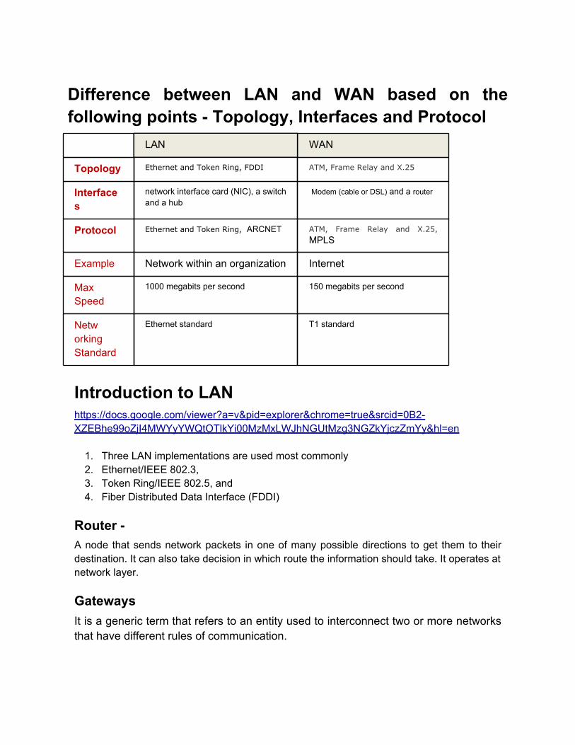
Difference between LAN and WAN based on the following points - Topology, Interfaces and Protocol
LAN WAN
Topology Ethernet and Token Ring, FDDI ATM, Frame Relay and X.25
Interfaces
network interface card (NIC), a switch and a hub
Modem (cable or DSL) and a router
Protocol Ethernet and Token Ring, ARCNET ATM, Frame Relay and X.25,
MPLS
Example Network within an organization Internet
Max Speed
1000 megabits per second 150 megabits per second
Networking Standard
Ethernet standard T1 standard
Introduction to LANhttps://docs.google.com/viewer?a=v&pid=explorer&chrome=true&srcid=0B2-XZEBhe99oZjI4MWYyYWQtOTlkYi00MzMxLWJhNGUtMzg3NGZkYjczZmYy&hl=en
1. Three LAN implementations are used most commonly2. Ethernet/IEEE 802.3,3. Token Ring/IEEE 802.5, and4. Fiber Distributed Data Interface (FDDI)
Router - A node that sends network packets in one of many possible directions to get them to their destination. It can also take decision in which route the information should take. It operates at network layer.
GatewaysIt is a generic term that refers to an entity used to interconnect two or more networks that have different rules of communication.

Introduction to WANhttps://docs.google.com/viewer?a=v&pid=explorer&chrome=true&srcid=0B2-XZEBhe99oMzY5YThmOTAtYmFmMC00NmFlLWJlMTItODVhMGEwNzYzYzU5&hl=en
OSI
Describe the following characteristics of OSI Layers: Information format, Addressing, Flow control and error checking
OSI Layer Addressing
Data Link Layer A data link layer address uniquely identifies each physical network connection of a network device. Data-link addresses sometimes are referred to as physical or hardware addresses1. End systems generally have only one physical network connection and thus have only one data-link address.2. Routers and other internetworking devices typically have multiple physical network connections and therefore have multiple data-link addresses.
Data Link Layer MAC Address:1. MAC addresses identify network entities in LANs that implement the IEEE MAC addresses of the data link layer2. MAC addresses are unique for each LAN interface.3. MAC addresses are 48 bits in length and are expressed as 12 hexadecimal digits
Network Layer A network layer address identifies an entity at the network layer of the OSI layers.1. Network addresses usually exist within a hierarchical address space and sometimes are called virtual or logical addresses.2. Routers and other internetworking devices require one network layer address per physical network connection for each network layer protocol supported. E.g. for TCP/IP Protocol, the network layer address is IP

OSI Layer Flow Control & Error Checking
Data Link Layer 1. One common error-checking scheme is the cyclic redundancy check (CRC), which detects and discards corrupted data.2. Error-correction functions (such as data retransmission) are left to higher-layer protocols.3. Sliding window protocol for Flow control
Transport Layer ● Use a fixed sliding-window protocol● Use a credit scheme
OSI Layer Information Format
The data and control information that is transmitted through internetworks takes a variety of forms. The terms used to refer to these information formats are not used consistently
Data Link Layer FramesCells - used in switched environments, such as Asynchronous Transfer Mode (ATM)
Network Layer PacketDatagram - usually refers to an information unit whose source and destination are network layer entities that use connectionless network service.
Transport Layer Segment
Application Layer Message

OSI Layer https://docs.google.com/viewer?a=v&pid=explorer&chrome=true&srcid=0B2-XZEBhe99oMDFjYTE1NTQtNTdlZi00ODM2LTljMDMtYjYyMGVjYjYwZWMx&hl=en
1. (Open Systems Interconnection) model defined by the International Organization for Standardization.
2. The OSI reference model is a conceptual model composed of seven layers, each
specifying particular network functions. The model was developed by the International Organization for Standardization (ISO) in 1984, and it is now considered the primary architectural model for inter-computer communications.
3. The basic idea of a layered architecture is to divide the design into small pieces. Each
layer adds to the services provided by the lower layers in such a manner that the highest layer is provided a full set of services to manage communications and run the applications.
4. The benefits of the layered models are
a. Modularity and clear interfaces, i.e. open architecture andb. Comparability between the different providers' components.
5. The basic elements of a layered model are services, protocols and interfaces. A
service is a set of actions that a layer offers to another (higher) layer. Protocol is a set of rules that a layer uses to exchange information with a peer entity. These rules concern both the contents and the order of the messages used. Between the layers service interfaces are defined. The messages from one layer to another are sent through those interfaces.
6. A set of layers and protocols is known as network architecture.

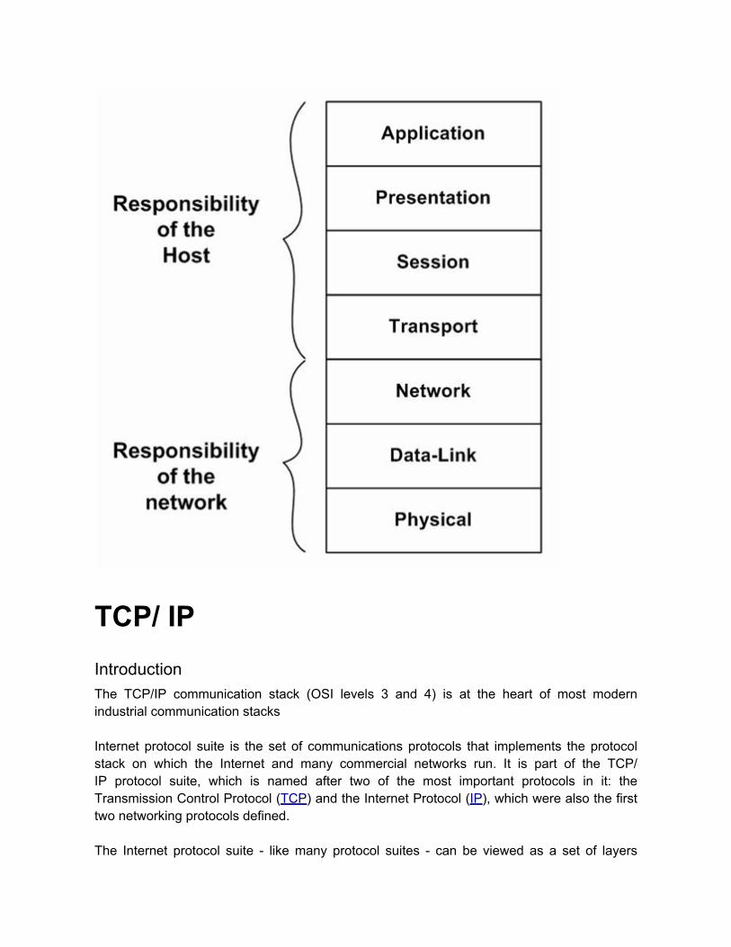
TCP/ IPIntroductionThe TCP/IP communication stack (OSI levels 3 and 4) is at the heart of most modern industrial communication stacks Internet protocol suite is the set of communications protocols that implements the protocol stack on which the Internet and many commercial networks run. It is part of the TCP/IP protocol suite, which is named after two of the most important protocols in it: the Transmission Control Protocol (TCP) and the Internet Protocol (IP), which were also the first two networking protocols defined. The Internet protocol suite - like many protocol suites - can be viewed as a set of layers

and can be compared to the OSI model. Each layer solves a set of problems involving the transmission of data, and provides a well-defined service to the upper layer protocols based on using services from some lower layers. Upper layers are logically closer to the user and deal with more abstract data, relying on lower layer protocols to translate data into forms that can eventually be physically transmitted. The original TCP/IP reference model consists (see Figure 5.1, “The TCP/IP protocol stack”) of 4 layers, but has evolved into a 5-layer model.Figure 5.1. The TCP/IP protocol stack


TCP (6 Marks)
How does the connection establishment and tear down takes place between TCP client and server nodes? Describe using time line diagram

What is the significance of ISN?The sequence numberidentifies the byte in the stream of data fromthe sending TCP to the receiving TCP that the first byte of data in this segment represents.When a new connection is being established, the SYN flag is turned on. The sequence number field contains the initial sequence number(ISN) chosen by this host for this connection. The sequence number of the first byte of data sent by this host will be the ISN plus one because the SYN flag consumes a sequence number.The acknowledgment numbercontains the next sequence number that the sender of the acknowledgment expects to receive.
Link Layer (6 Marks)
What is Link Layer1. This is one of the TCP/IP layer2. Send/Receive IP datagrams for IP Module3. Link Layer Protocols
a. ARP Requests and Replies

b. RARP Requests and Replies4. Different link layers –
a. Ethernet,b. Token ring,c. FDDId. Serial Lines
i. SLIP &ii. PPP
e. Loopback driver5. Two standards:
a. Ethernetb. IEEE 802
6. MTU and path MTUa. There is a limit on the size of the frame for both Ethernet and 802.3
encapsulations. This limits the number of bytes of data to 1500 and 1492, respectively. This characteristic of the link layer is called the MTU, its maximum transmission unit.
b. When two hosts on the same network are communicating with each other, it is the
MTU of the network that is important. But when two hosts are communicating across multiple networks, each link can have a different MTU. The important numbers are not the MTUs of the two networks to which the two hosts connect, but rather the smallest MTU of any data link that packets traverse between the two hosts. This is called the path MTU.
Ethernet & 802.3 https://docs.google.com/viewer?a=v&pid=explorer&chrome=true&srcid=0B2-XZEBhe99oNWE1ZTUwODMtZmI4YS00Njk3LTg3ZmUtMDJhNzI0NTY1Yjcy&hl=en
1. Ethernet was developed by Xerox Corporation’s Palo Alto Research Center (PARC) in the 1970s.
2. Ethernet was the technological basis for the IEEE 802.3 specification, which was
initially released in 1980.
3.Shortly thereafter, Digital Equipment Corporation, Intel Corporation, and XeroxCorporation jointly developed and released an Ethernet specification (Version 2.0) that is substantially compatible with IEEE 802.3.
4. Ethernet/IEEE 802.3 Similaritya. Both are CSMA/CD LANs. Stations on a CSMA/CD (Carrier Sense Multiple
Access / Collision Detection) LAN can access the network at any time.b. Both Ethernet and IEEE 802.3 LANs are broadcast networks.c. Ethernet and IEEE 802.3 are implemented in hardware.d. Both of these protocols specify a bus topology
5. Differences between Ethernet and IEEE 802.3 LANs are subtle.
a. Ethernet provides services corresponding to Layers 1 and 2 of the OSI reference model, while IEEE 802.3 specifies the physical layer (Layer 1) and the channel-access portion of the link layer (Layer 2), but does not define a logical link control protocol.
b. IEEE 802.3 specifies several different physical layers, whereas Ethernet defines
only one.
c. Ethernet is most similar to IEEE 802.3 10Base5.
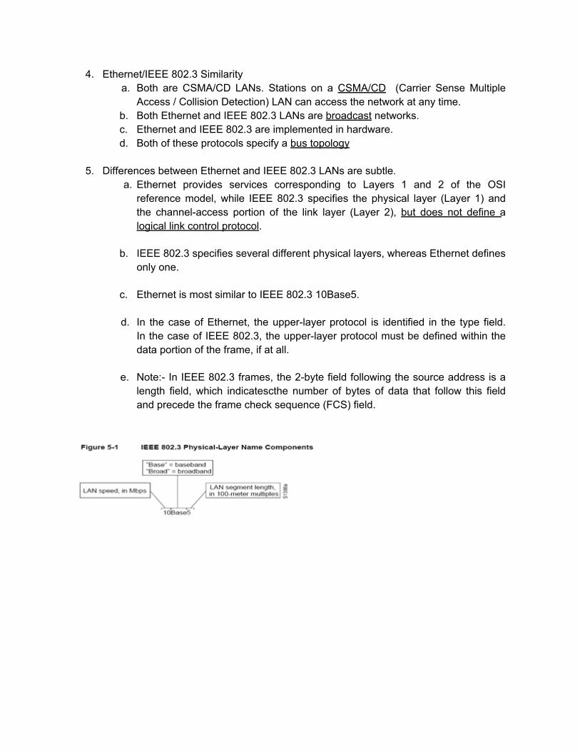
d. In the case of Ethernet, the upper-layer protocol is identified in the type field. In the case of IEEE 802.3, the upper-layer protocol must be defined within the data portion of the frame, if at all.
e. Note:- In IEEE 802.3 frames, the 2-byte field following the source address is a
length field, which indicatescthe number of bytes of data that follow this field and precede the frame check sequence (FCS) field.
SLIP https://docs.google.com/viewer?a=v&pid=explorer&chrome=true&srcid=0B2-XZEBhe99oY2RiZWQ2NGYtZjdhNC00YTg5LTk4MzEtMjRjMWQ0M2E3NjFi&hl=en
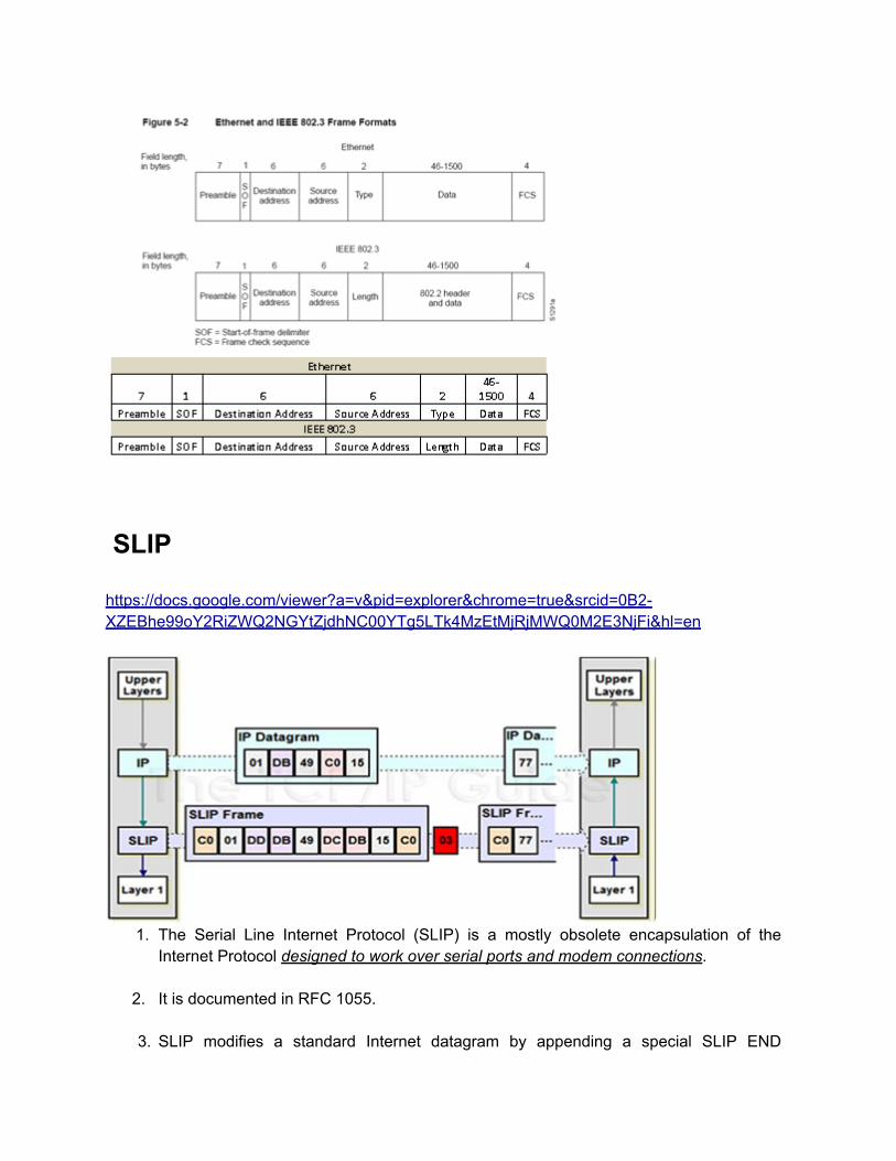
1. The Serial Line Internet Protocol (SLIP) is a mostly obsolete encapsulation of the Internet Protocol designed to work over serial ports and modem connections.
2. It is documented in RFC 1055.
3. SLIP modifies a standard Internet datagram by appending a special SLIP END

character to it, which allows datagrams to be distinguished as separate.
4. SLIP has been largely replaced by the Point-to-Point Protocol (PPP), which is better engineered, has more features and does not require its IP address configuration to be set before it is established.
PPP
1. The Point-to-Point Protocol (PPP) originally emerged as an encapsulation protocol for transporting IP traffic over point-to-point links.
2. RFC 1548 and RFC 1332
3. PPP provides a method for transmitting datagrams over serial point-to-point links,
which include the following three components:a. A method for encapsulating datagrams over serial linksb. An extensible LCP to establish, configure, and test the connectionc. A family of NCPs for establishing and configuring different network layer
protocols4. Six fields make up the PPP frame.
5. The PPP LCP provides a method of establishing, configuring, maintaining, and
terminating the point-to-point connection
IP Layer (7 Marks)
Internet Protocolhttps://docs.google.com/viewer?a=v&pid=explorer&chrome=true&srcid=0B2-

XZEBhe99oMzRjMjJjODEtYjk0NS00ZTJkLTk2MTAtYjAxOTY3MzU1MmU3&hl=en
Internet Protocols IntroductionThe Internet protocols are the world’s most popular open-system (nonproprietary) protocol suite because they can be used to communicate across any set of interconnected networks and are equally well suited for LAN and WAN communications. The Internet protocols consist of a suite of communication protocols, of which the two best known are the Transmission-Control Protocol (TCP) and the Internet Protocol (IP). Internet protocols span the complete range of OSI model layers

IP - General
● The purpose of IP is to provide unique global computer addressing to ensure that two computers communicating over the Internet can uniquely identify one another.
● The current and most popular network layer protocol in use today is
IPv4;
● IPv4 RFC-791
● IPv4 is a data-oriented protocol to be used on a packet switched internetwork. It is a best effort protocol in that it doesn't guarantee delivery.
○ It doesn't make any guarantees on the correctness of the data; it may result in duplicated packets and/or packets out-of-order. These aspects are addressed by an upper layer protocol (e.g., TCP, and partly by UDP).
● All TCP, UDP, ICMP data transmitted as IP datagrams.
● Provides unreliable, connectionless datagram delivery service.
● Hosts and routers have a routing table used for all routing decisions.
● Three types of routes:
○ Host specific,○ network specific and○ default routes
What are the functions performed at IP Layer (5 marks)

The internet protocol implements two basic functions:
● Addressing and § The internet modules use the addresses carried in the internet header to transmit internet datagrams toward their destinations. The selection of a path for transmission is called routing.
● Fragmentation § Fragmentation of an internet datagram is necessary when it originates in a local net that allows a large packet size and must traverse a local net that limits packets to a smaller size to reach its destination. The internet fragmentation and reassembly procedure needs to be able to break a datagram into an almost arbitrary number of pieces that can be later reassembled. § The internet modules use fields in the internet header to fragment and reassemble internet datagram when necessary for transmission through "small packet" networks..
Assume an Ethernet and a UDP datagram with 2000 bytes of user data. How many fragments are transmitted and what is the offset and length of each fragment? (5 marks) Data @ IP layer: = Given user data: 2000 bytes + UDP header length: 8 bytes = 2008 bytesIP header - 20 byte Max Ethernet frame data size (MTU): 1500 bytes So, we have an IP message 2028 bytes (including the 20 bytes of IP header) that needs to be sent over a link with MTU 1,500 bytes

MF Offset Data
0 0 2,008 bytes
First Fragmentation 1500 MTU
MF Offset Data
0 0 1480 bytes
Fragment 1; Data bytes 0-1479
MF Offset Data
0 185 528 bytes
Fragment 2; Data bytes 1480-2,007
For example, consider an IP message 12,000 bytes wide (including the 20 byte IP header) that needs to be sent over a link with MTU 3,300 bytes.
MF Offset Data
0 0 11,980 bytes
First Fragmentation 3300 MTU

MF Offset Data
1 0 3,280 bytes
Fragment 1; Data bytes 0-3,279
MF Offset Data
1 410 3,280 bytes
Fragment 2; Data bytes 3280-6,559
MF Offset Data
1 820 3,280 bytes
Fragment 3; Data bytes 6,560-9,839
MF Offset Data
1 1,230 2,140 bytes
Fragment 4; Data bytes 9,840-11,979 Reference: http://www.tcpipguide.com/free/t_IPMessageFragmentationProcess-2.htm http://www.tcpipguide.com/free/t_IPMessageFragmentationProcess-3.htm

What is MTUEach device on an IP internetwork, must know the capacity of its immediate data link layer connection to other devices. This capacity is called the maximum transmission unit (MTU) of the network. If an IP layer receives a message to be sent across the internetwork, it looks at the size of the message and then computes how large the IP datagram would be after the addition of the 20 or more bytes needed for the IP header. If the total length is greater than the MTU of the underlying network, the IP layer will fragment the message into multiple IP fragments. So, if a host is connected using an Ethernet LAN to its local network, it may use an MTU of 1,500 for IP datagrams, and will fragment anything larger. Figure 88 shows an example of differing MTUs and fragmentation.
Referenceshttp://www.tcpipguide.com/free/t_IPDatagramSizetheMaximumTransmissionUnitMTUandFrag-2.htm
IPv4 Address Every interface on an internet must have a unique Internet Address, (called IP address). These addresses are 32-bit numbers.

IP Packet structureAn IP packet consists of two sections: o Header- The header consists of 13 fields, of which only 12 are required. The 13th field is optional o Data

References:· http://www.consultants-online.co.za/pub/itap_101/html/ch05s03.html#tcp_ip.sec_3.2
ICMP1. Internet Control Message Protocol (ICMP) is a network-layer Internet protocol
The Internet Control Message Protocol (ICMP) is one of the core protocols of the Internet protocol suite. It is chiefly used by networked computers' operating systems to send error messages - indicating, for instance, that a requested service is not available or that
2. a horeachedst or router could not be 3. Acted on by IP or higher layer TCP, UDP
4. ICMP Messages - ICMPs generate several kinds of useful messages, including
a. Destination Unreachable
i. When an ICMP destination-unreachable message is sent by a router, it means that the router is unable to send the package to its final destination. The router then discards the original packet.
ii. Destination-unreachable messages include four basic types: network

unreachable, host unreachable, protocol unreachable, and port unreachable
b. Echo Request and Reply
i. An ICMP echo-request message, which is generated by the ping command, is sent by any host to test node reach-ability across an internetwork. The ICMP echo-reply message indicates that the node can be successfully reached.
c. Redirect
i. An ICMP Redirect message is sent by the router to the source host to stimulate more efficient routing.
ii. ICMP redirects allow host routing tables to remain small
d. Time Exceeded
i. An ICMP Time-exceeded message is sent by the router if an IP packet’s Time-to-Live field (expressed in hops or seconds) reaches zero
e. Router Advertisement and Router Solicitation
i. ICMP Router-Discovery Protocol (IDRP) IDRP uses Router-Advertisement and Router-Solicitation messages to discover the addresses of routers on directly attached subnets.
ii. Each router periodically multicasts Router-Advertisement messages
from each of its interfaces. Hosts then discover addresses of routers on directly attached subnets by listening for these messages. Hosts can use Router-Solicitation messages to request immediate advertisements rather than waiting for unsolicited messages.
f. Address Mask Request/ Address Mask Reply
i. The ICMP address mask request is intended for a diskless system to obtain its subnet mask at bootstrap time. The requesting system broadcasts its ICMP request.
g. Timestamp / Timestamp Reply
i. The ICMP timestamp request allows a system to query another for the current time. The recommended value to be returned is the number of milliseconds since midnight, Coordinated Universal Time (UTC).
5. If an ICMP message cannot be delivered, no second one is generated. This is to avoid
an endless flood of ICMP messages.
6. ICMP is documented in RFC 792.

7. The version of ICMP for Internet Protocol version 4 is also known as ICMPv4, as it is
part of IPv4
8. ICMP differs in purpose from TCP and UDP in that it is usually not used directly by user network applications. One exception is the ping tool, which sends ICMP Echo Request messages
9. Many commonly-used network utilities are based on ICMP messages.
a. The traceroute command - The traceroute command is implemented by
transmitting UDP datagrams with specially set IP TTL header fields, and looking for ICMP Time to live exceeded in transit (above) and "Destination unreachable" messages generated in response.
b. The related ping utility is implemented using the ICMP "Echo request"
and "Echo reply" messages.
10. ICMP messages encapsulated within an IP datagram

ARP / RARP
Converting IP Address to MAC Address using ARP
ARP
1. Address Resolution Protocol (ARP) is a link-layer Internet protocol

2. (rfc 826)
3. Provides mapping between 32 bit IP address and 48 bit MAC address
4. An ARP cache is maintained on each host. ARP cache is maintained to store recent
mappings. Normal expiration time is 20 min
5. We can examine the ARP cache with the arp command. The -a option displays all entries in the cache: % arp-a
6. For two machines on a given network to communicate, they must know the other
machine’s physical (or MAC) addresses. By broadcasting Address Resolution Protocols (ARPs), a host can dynamically discover the MAC-layer address corresponding to a particular IP network-layer address. After receiving a MAC-layer address, IP devices create an ARP cache to store the recently acquired IP-to-MAC address mapping, thus avoiding having to broadcast ARPS when they want to recontact a device. If the device does not respond within a specified time frame, the cache entry is flushed.
7. Proxy ARP - Proxy ARP lets a router answer ARP requests on one of its networks for a host on
another of its networks. This fools the sender of the ARPrequest into thinking that the router is the destination host, when in fact the destination host is "on the other side" of the router. The routeris acting as a proxy agent for the destination host, relaying packets to it from other hosts.

RARP1. Link Layer Protocol
2. In addition to the Reverse Address Resolution Protocol (RARP) is used to map MAC-
layer addresses to IP addresses. RARP, which is the logical inverse of ARP, might be used by diskless workstations that do not know their IP addresses when they boot. RARP relies on the presence of a RARP server with table entries of MAC-layer-to-IP address mappings.
3. RFC 903
4. RARP is used to obtain IP address when bootstrapping
5. Packet format same as ARP
6. RARP req. is broadcast asking for sender’s IP address, MAC address provided.
7. Reply is normally unicast. It is optional in TCP/IP implementation
Differentiate between RARP and BOOTPRARP (Reverse ARP) BOOTP (BOOTstrap Protocol)
It translates a MAC (Medium Access Control) address, which is the address hard-wired into network interface cards, into the IP address that has been assigned to the system with the MAC address.
BOOTP was created at a later time to enhance what RARP provides. BOOTP obtains an IP address, a gateway address, and a name server address from the server running the BOOTP protocol.
The primary limitations of RARP are that each MAC must be manually configured on a central server, and that the protocol only conveys an IP address and this leaves configuration of subnetting, gateways, and other information to other protocols or the user
RARP is now obsoleted by BOOTP and the more modern DHCP, which both support a much greater feature set than RARP.

IPv6:
IPv6: IPv4 Conversion OR What are the modifications required to port the IPv4 applications to work on IPv6 network? Why and where we need the change
● Numerical addresses – IPv4, 32 bit address / IPv6, 128 bit address● Typical IPv4 & IPv6 code sequence from server side and client side is exactly same● The size of the IP address is visible to an application through the socket interface● Changes required to:
○ Parts of the API that exposes the size of the IP address (new data structures required)
○ Parts of the application that manipulates the IP address

IPV4 TunnelingTwo IPv6 nodes are separated by an IPv4 network. By using dual-stack routers, a tunnel is dug by encapsulating an IP packet within the payload of another packet. The dual-stack router on one end of the communication takes IPv6 packets from the sender, encapsulates them within IPv4 packets, then forwards the packets across the IPv4 packets, extracts the IPv6 packets inside and forwards the IPv6 packets to their proper destination.
Dual StackNode has both IPv4 and IPv6 stacks and addresses• DNS resolver
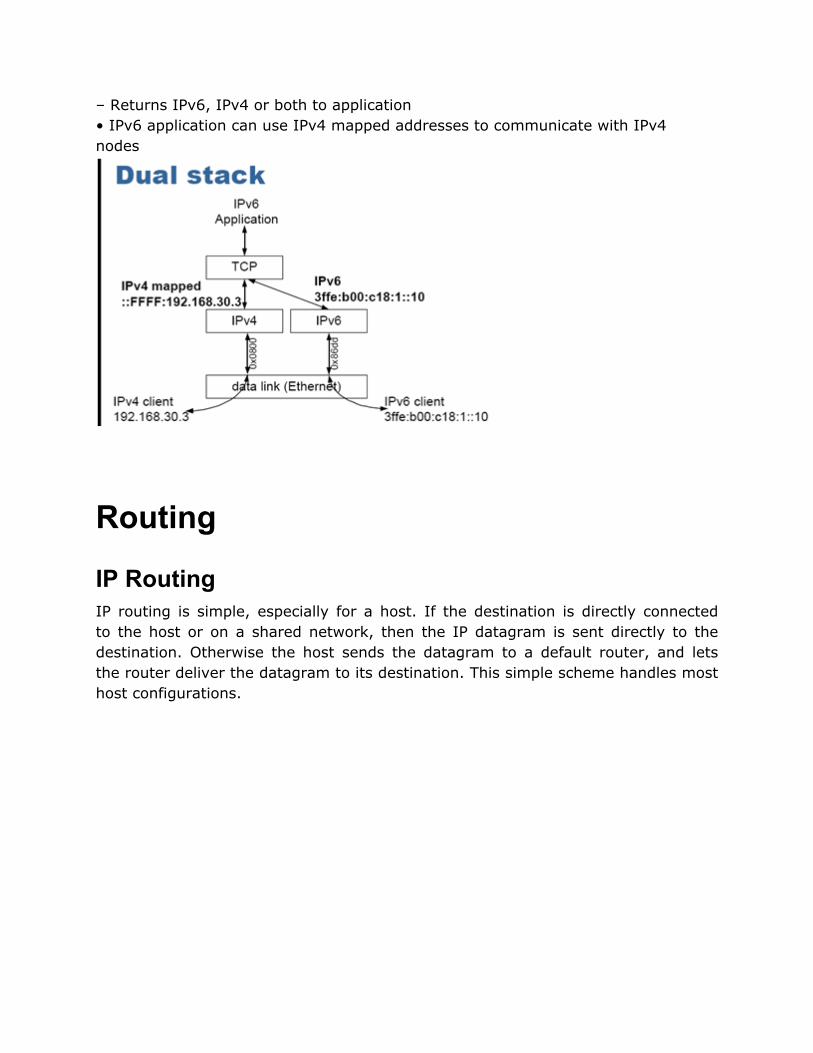
– Returns IPv6, IPv4 or both to application• IPv6 application can use IPv4 mapped addresses to communicate with IPv4 nodes
Routing
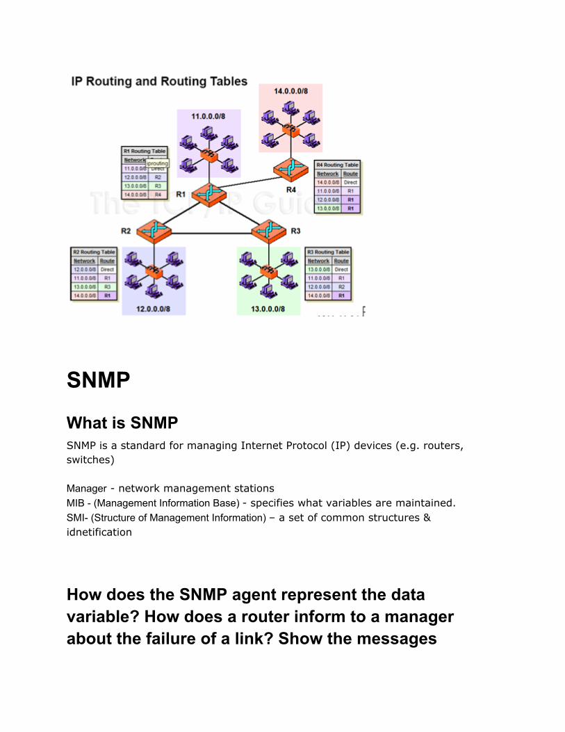
IP RoutingIP routing is simple, especially for a host. If the destination is directly connected to the host or on a shared network, then the IP datagram is sent directly to the destination. Otherwise the host sends the datagram to a default router, and lets the router deliver the datagram to its destination. This simple scheme handles most host configurations.

IP performs following steps when it searches its routing table.
● Search for a matching host address.● Search for a matching network address.● Search for a default entry.
IP performs the routing mechanism while a routing daemon normally provides the routing policy.● Routing mechanism (Done by IP)-● Searching the routing table and decide which interface to send a packet out.● Routing policy (provided by routing daemon) - A set of rules that decides which routes go into the routing table● IP performs following steps when it searches its routing table.● Search for a matching host address.● The information contained in the routing table drives all the routing decisions made by IP.● Initialize at boot time● Simple route table: Flags-U, G, H, D, M● Search for a matching network address.● Search for a default entry. ● ICMP redirect error for route table update
Explain the operation of Routing Information protocol (RIP). State some of the problems in RIP V1.0 Background

Routing protocols implement routing algorithms.· Interior Gateway Routing Protocol (IGRP): OSPF, RIP.· Exterior Gateway Protocol (EGP): BGP Routing Information Protocol (RIP 1.0)Routing protocols implement routing algorithms. RIP is a distance-vector protocol. The term distance-vector means the messages sent by RIP contain a vector of distances (hop counts).Each router updates its routing table based on the vector of these distances that it receives from its neighbors.
● The RIP messages are carried in IP datagram.● The specification for RIP is RFC 1058.● Format of RIP Message
● A command of 1 is a request, and 2 is a reply. A request asks the other
system to send all or part of its routing table. A reply contains all or part of the sender's routing table.
● The version is normally 1.● The address family (which is always 2 for IP addresses), an IP address, and
an associated metric. Normal OperationInitialization - When the daemon starts it determines all the interfaces that are up and sends a request packet out each interface, asking for the other router's complete routing table. On a point-to-point link this request is sent to the other end. The request is broadcast if the network supports it. The destination UDP port is 520 Request received - The entire routing table is sent to the requestor. Response received - The response is validated and may update the routing table. New entries can be added, existing entries can be modified, or existing entries can be deleted.

Regular routing updates - Every 30 seconds, all or part of the router's entire routing table is sent to every neighbor router. •Triggered updates. These occur whenever the metric for a route changes. The entire routing table need not be sent -only those entries that have changed must be transmitted. RIP1.0 problems
● RIP has no knowledge of subnet addressing.● RIP takes a long time to stabilize after the failure of a router or a link.● The use of the hop count as the routing metric omits other variables that
should be taken into consideration.● A maximum of 15 for the metric limits the sizes of networks on which RIP
can be used. RIP 2 solves the problem
● Allows more information to be included in RIP Packets.● The subnet mask for each entry applies to the corresponding IP address● The route tag exists to support exterior gateway protocol● A simple authentication scheme is provided● Supports multicasting in addition to broadcasting
Explain OSPF Protocol of the Internet Open Shortest Path First (OSPF)· OSPF is a newer alternative to RIP as an interior gateway protocol.· OSPF is a link-state routing protocol that calls for the sending of link-state advertisements (LSAs) to all other routers within the same hierarchical area. · Each router actively tests the status of its link to each of its neighbors, sends this information to its other neighbors, which then propagate it throughout the autonomous system. Each router takes this link-state information and builds a complete routing table. · All OSPF packets begin with a 24-byte header OSPF Features · A link-state protocol will always converge faster than a distance-vector

protocol.· OSPF has its own value for the protocol field in the IP header.· Supports Subnet· Uses multicasting instead of broadcasting to reduce the load· A simple authentication scheme can be used· Load balancing is done
Routing Table Each entry in the routing table contains the following information: 1. Destination IP address2. IP address of a next-hop router3. Flags4. Specification of which network interface the datagram should be passed to for transmission. Flags
1. U The route is up.
2. G The route is to a gateway (router).
3. H The route is to a host
4. D The route was created by a redirect.
5. M The route was modified by a redirect.Initializing a Routing Table5. Execute the route command6. Run a routing daemon7. Use the newer router discovery protocol
SNMP
What is SNMPSNMP is a standard for managing Internet Protocol (IP) devices (e.g. routers, switches) Manager - network management stationsMIB - (Management Information Base) - specifies what variables are maintained.SMI- (Structure of Management Information) – a set of common structures & idnetification
How does the SNMP agent represent the data variable? How does a router inform to a manager about the failure of a link? Show the messages

exchanged between them.Each device (node) maintains one or more variables that describe its state. In the SNMP literature, these variables are called objects. The collection of all possible objects in a network is given in a data structure called the MIB (Management Information Base). MIB is a set of named items that an SNMP agent understands. To monitor or control a remote computer, a manager must fetch or store values to MIB variables (objects).

Firewall
What is firewall, explain two types of firewall A firewall is a secure and trusted machine that sits between a private network and a public network. The firewall machine is configured with a set of rules that determine which network traffic will be allowed to pass and which will be blocked or refused.

Types of Firewalls A stateless firewall is one which does not keep any state information between packets. Each packet is examined and handled based only on the information contained within that packet. A stateful firewall keeps track of "sessions" between packets. · "statefulpacket inspection"· "protocol inspection“ In the case of FTP, a stateful firewall would monitor the control channel, and look for the PASV or PORT commands used to open the TCP connection for the data channel. It would then allow that TCP connection through as well. A stateful firewall is therefore more secure than a stateless firewall
What is IP packet filtering?

IP filtering is simply a mechanism that decides which type of IP datagrams will be processed normally and which will be discarded. Criteria to determine which data grams you wish to filter.· Protocol type: TCP, UDP, ICMP etc.· Socket Number (for TCP/UDP)· Datagram Type: SYN/ACK, data, ICMP Echo· Datagram source and destination Address IP filtering is a network layer facility
How does filtering mechanism work 1. The IP datagram is received (1) a. The incoming IP datagram is examined to determine if it is destined for a process on this machine. 2. If the datagram is for this machine, it is processed locally. (2) 3. If it is not destined for this machine, a search is made of the routing table for an appropriate route and the datagram is forwarded to the appropriate interface or dropped if no more can be found. (3)

4. Datagrams from local processes are sent to the routing software for forwarding to the appropriate interface. (4) a. The outgoing IP datagram is examined to determine if there is a valid route for it to take, if not, it is dropped. The IP datagram is transmitted. (5)
Malicious Programs
Explain the following malicious program - Trojan Viruses The software threats or malicious programs can be divided into two categories· That need a host program· That are independent

TrojansA Trojan horse is an unauthorized program contained within a legitimate program. A Trojan horse is a static entity: malicious code nested within an otherwise harmless program.Trojans cannot travel from machine to machine unless the file that contains the
Trojan also travels with it. Trojans are created strictly by programmers. The
majority of Trojans are nested within compiled binaries. Trojans represent a very high level of risk, mainly for reasons stated: · Difficult to detect. · In most cases, Trojans are found in binaries, which remain largely in non-human-readable form. · Can affect many machines.
VirusesA computer virus is a program, sometimes (but not necessarily) destructive, that
is designed to travel from machine to machine, "infecting" each one along the way. This infection usually involves the virus attaching itself to other files. Anti-virus approaches· Do not allow· Detection· Identification· Removal
WormA worm actively seeks out more machines to infect and each machine that is infected serves as a launching pad for attacks on other machines. A worm does not perform any destructive actions, and instead, only consumes system resources to bring it down. Network programs use network connections to spread from system to system. To replicate itself, a network worm uses: · Electronic mail facility · Remote execution capability · Remote login capability
IPSec
Differentiate SSL with SET Protocol The SET (Secure Electronic Transaction) protocol is an open encryption and security specification designed for protecting credit card transactions on the Internet. SET services can be summarized as follows: 1. Provides a secure communication channel2. Provides authentication by use of digital certificates.

3. Ensures confidentiality SET Vs SSLSSL and SET are both used for facilitating secure exchange of information, their purposes are quite different. · SSL is primarily used for secure exchange of information of any kind between only two parties (a client and a server) · SET is specifically designed for conducting e-commerce transactions. SET involves a third party as a payment gateway, which is responsible for issues such as credit card authorization, payment to the merchant etc.
How does the SSL work
It is an Internet protocol for secure exchange of information between a Web browser and a Web server.

Provides two basic security services:· authentication· confidentiality
SSL can be conceptually considered as an additional layer in the TCP/IP protocol
stack. The SSL layer is located between the application layer and the transport layer. How SSL WorkSSL has three sub-protocols,· Handshake protocol· Record protocol· Alert protocolHandshake protocolConsists of a series of messages between the client and the serverThe handshake protocol is made up of four phases. These phases are: 1. Establish Security capabilities 2. Server authentication and key exchange 3. Client authentication and key exchange 4. Finish Record protocolIt takes an application message as input. First it fragments it into smaller blocks, optionally compresses each block, adds MAC, encrypts it, adds a header and gives it to the transport layer. This protocol provides two services to an SSL connection as follows: Confidentiality: This is achieved by using the secret key that is defined by the handshake protocol. Integrity: The handshake protocol defines a shared secret key (MAC) that is used for assuring the message integrity. Alert protocolWhen either the client or the server detects an error, the decrypting party sends an alert message to the other party. Action taken· Immediately close the SSL connection.· Destroy the session identifiers, secrets and keys associated with this

connection before it is terminated.· Each alert message consists of two bytes.o 1st byte - The type of error.o 2nd byte - The actual error.
What are IPSEC IPSec is a set of IP extensions developed by IETF( Internet Engineering Task Force) to provide cryptographic security services compatible with the existing IP standard (IP v.4). · IPSec can protect any protocol that runs on top of IP, for instance TCP, UDP, and ICMP. · IPsec provides security services at the IP layer by enabling a systemo To select required security protocols,o Determine the algorithm(s) to use for the service(s),o Put in place any cryptographic keys required to provide the requested services. Goals 1. Privacy to ensure data confidentiality2. Integrity to guarantee that data has not been tampered with.3. Authenticity to protect against identity spoofing.4. Robustness to prevent replay attacks. Architecture1. Security Protocols --Authentication Header (AH) and Encapsulating Security Payload (ESP)2. Security Associations --what they are and how they work, how they are managed, associated processing3. Key Management --manual and automatic (The Internet KeyExchange (IKE))4. Algorithms for authentication and encryption
Encryption

State the two problems in symmetric key encryption? (5 marks)
What are the three requirements for public-key encryption? (5 marks)
Explain the RSA algorithm by giving an example? (6 marks)
Appendix
MAC Address
OSI Services Layer 1Physical Layer
Hardware used to create the network and transmit data - twisted pair, coax, fiber optic cables, hubs,

repeaters, etc.Layer 2Data Link Layer
Divided into 2 sub-layers: Media Access Control (MAC) and Logical Link Control (LLC) layersPhysical Addressing - MAC addresseshardware used: bridges and switches
Layer 3Network Layer
Switching and Routing, IP addressesuses layer 3 switches, routers
Layer 4Transport Layer
End to end connections and reliability, TCP protocol
Layer 5Session Layer
Manages connections between applications - controlling TCP/IP sessions
Layer 6Presentation Layer
Transforms data into a form acceptable by layer 7; in reverse transforms data so it is acceptable to lower levelsMIME encoding, encryption, etc.
Layer 7Application Layer
Applications and end-user processesEmail, Telnet, Web Apps, etc.
IPV6
Basics Features (IPv6)· RRFC 2460· Increase of address size from 32 bits to 128 bits· Simplified Header· Improved Support for Extensions and Options· Flows· Authentication and privacy ExampleIPv6 represented by 16bit hex separated by colon. For example FF02:0:0:0:0:1:200E:8C6C

Ver (4 Bit)Traffic Class (8 Bit) Flow Level (20 Bit)
Payload length (16 Bit)Next Header (8 Bit) Hop Limit (8 Bit)
Source Address(128 Bit)
Destination Address(128 Bit)
RFC2732 states that IPv6 addresses in URIs should be delimited by square brackets [ ].– http://[3ffe:0b00::1]/index.html