Embed Size (px)
Citation preview

NATIONAL RADIO llNSTITUTE
,) Complete Course in ' PRACTICAL RADIO _
-qv- r>
.j , cm,.....................` ; IIIIIIIIIIIIl1UINlllllllllllllllllllll111111
= 11111111111111111illllllllll1111 143
_
0
MOM
"Z1 1111111I1111111111W111111111111118111111111111111111111111111111111111111111111111111111I111111111111I1111111111111111 I,a
Radio .Trician
Lesson Text No. 27
RADIO BATTERY
CHARGERS
.1111
10riginators of Radio Home Study Courses Established 1914
Washington, D. C.
www.americanradiohistory.com

Pausing For Thought A Personal Message from J. E. Smith
Concentration in study does not mean steady reading without pause. That may be concentration all right, but it is not a profit- able kind of concentration. One should stop now and then and turn over in his own mind what he has been reading.
That is the only way to insure that the ideas he has gained, or thinks he has gained, are really clear to him. It is the only way, too, in which he can make them genuinely his own and be able in the future to apply them to circumstances in which he, himself, may be placed.
Copyright 1929, 1930 by
NATIONAL RADIO INSTITUTE Washington, D. C.
BFbMb143(I Printed in U.S.A.
www.americanradiohistory.com
II 2
Radio-Trician's REG. U. S. PAT. OFF.
Complete Course in Practical Radio NATIONAL RADIO INSTITUTE WASHINGTON, D. C.
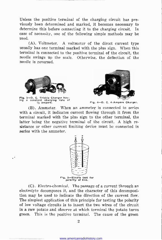
RADIO BATTERY CHARGERS The use of a storage battery for operating radio receiving
sets requires some provision for charging the battery. Either you must utilize some Battery Service Station to which you can send or take the battery to be charged, or you must have a bat- tery charger of your own. The latter plan is by far the most satisfactory and economical to the average man, and to meet his needs there have been a wide variety of chargers placed on the market, but before making your selection of a battery charger,
I/O VOLT I/O VOLT DC. MAINS D.C. MAINS
/USE
AMMETER
6 VOLT BATT ERV
VARIABLE RESISTANCE
Fig. 1-Charging a 6 -volt storage battery from a D. C. line using a variable resistance to regulate the
charge rate.
FOSE
AMMETER
LAMPS USED 6 VOLT AS RESISTANCE BATTERY Fig. 2-Charging a 6 -volt storage battery from a D. C. line using lamps for resistance to regulate
charge rate.
find out from your Electric Light Company whether you are being supplied with alternating current or direct current; also what is the voltage of the line and the frequency if it is alter- nating current.
CHARGING BATTERIES FROM D. C. LINE Assuming that the source of supply is direct current, it is
only necessary to procure a special resistance for the purpose (see Figure 1) which may be purchased or as an alternative, you may use a few electric light bulbs as shown in Figure 2.
SIMPLE METHODS OF DETERMINING POLARITY In charging storage batteries, the positive terminal of the
circuit must be connected to the positive terminal of the battery. 1
rtr www.americanradiohistory.com
Unless the positive terminal of the charging circuit has pre- viously been determined and marked, it becomes necessary to determine this before connecting it to the charging circuit. In case of necessity, one of the following simple methods may be used.
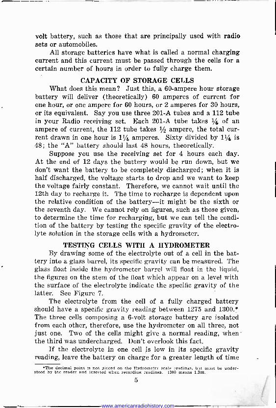
(A). Voltmeter. A voltmeter of the direct current type usually has one terminal marked with the plus sign. When this terminal is connected to the positive terminal of the circuit, the needle swings up the scale. Otherwise, the deflection of the needle is reversed.
Fig. 3-D. C. Trickle Charger hav- ing a constant charging rate of
1/2 ampere. Fig. 4-D. C. 4 -Ampere Charger.
(B). Ammeter. When an ammeter is connected in series with a circuit, it indicates current flowing through it from the terminal marked with the plus sign to the other terminal, the latter being the negative terminal of the circuit. A high re- sistance or other current limiting device must be connected in series with the ammeter.
Fig. 5-Simple test for polarity of line.
(C). Electro -chemical. The passage of a current through an electrolyte decomposes it, and the character of this decomposi- tion may be used to indicate the direction of the current flow. The simplest application of this principle for testing the polarity of low voltage circuits is to insert the two wires of the circuit in a raw potato and observe at which terminal the potato turns green. This is the positive terminal. The cause of the green
2
www.americanradiohistory.com

color is the copper which is removed from the wire by the cur- rent. If this method is employed, care must be taken not to short circuit the source of current. Either a resistance must be connected in series or the ends of the wires must not make contact with each other.
Another application of the principle is to immerse the two wires in a glass tumbler in which is dissolved a small amount of ordinary table salt. The wire at which there is violent bubbling is the negative wire and should go to the negative terminal of the battery. See Figure 5.
(D). Compass indicator. If the north pole of the compass needle points away from the observer, when the compass is placed above a wire carrying a small current, then the direction of the
WIRE CARRYING CURREN7
O/RECT/ On/ COMPASS NEEDLE OF CURR ENT
Fig. 6-Current in a wire below compass needle deflects compass needle indicating polarity of line.
current flow is from right to left, and the right end of the wire is positive with respect to the left hand end. See Figure 6.
(E). By using white filter paper immersed in a solution of sodium sulphate to which has been added a small quantity of phenol phthalein, the result is a colored paper which, if moistened, will turn violet when touched with the negative wire, but re- mains unchanged when in contact with the positive. The paper retains this property indefinitely and is sensitive to a very feeble current. Blue print paper may be used for the same purpose, a white spot developing around the negative pole when the paper is in contact with the wire, while the positive wire has no effect on it.
OHM'S LAW
In order to know how to connect and charge a storage bat- tery, it is quite necessary to understand the relation between the electrical quantities associated with any ordinary electric cir-
3
www.americanradiohistory.com

cuit carrying a direct current. The flow of electricity in a cir- cuit is called the current and is measured in a unit called the ampere; the electric force producing the current is called the voltage, potential, or electromotive force, and is measured in a unit called the volt; while the opposition offered by the circuit to the passage of electricity through it is called the resistance, which is measured in a unit called the ohm.
These three quantities, namely, electromotive force, current and resistance bear a definite relation to each other and this relation is expressed by the following simple equation, which is called Ohm's Law.
Current -Electromotive Force Resistance
Resistance - Electromotive Force Current
Electromotive Force = Current X Resistance As an example, if the voltage is increased, the resistance
remaining constant, there will be a proportional increase in cur- rent, or if the resistance should be reduced, the voltage remain- ing constant, there will be a proportional increase in the current, etc. In other words, the current in the circuit may be varied by changing either the voltage acting on the circuit, or the resistance of the circuit.
It can be seen from the above that if the battery were con- nected directly across the line, there would be a short circuit as the internal resistance of a storage battery is very low. There- fore, to regulate the value of the charging current, it is neces- sary to insert a resistance in series with the battery.
A storage battery or accumulator, as it is sometimes called, is a number of cells in which a chemical action is first produced by an electrical current through the cells from some external source of energy, after which the cells are capable of delivering a current to an external circuit by means of a secondary or reversed chemical action. The process of storing electrical energy by sending a current through the cells from some external source of energy is called charging. When the cells are produc- ing a current in an external circuit or supplying energy, they are said to be discharging.
The following discussion will be confined to the charging of storage batteries. As an example, suppose a 110 -volt direct current circuit is available and it is desired to charge a small 6-
4
www.americanradiohistory.com
volt battery, such as those that are principally used with radio sets or automobiles.
All storage batteries have what is called a normal charging current and this current must be passed through the cells for a certain number of hours in order to fully charge them.
CAPACITY OF STORAGE CELLS What does this mean? Just this, a 60 -ampere hour storage
battery will deliver (theoretically) 60 amperes of current for one hour, or one ampere for 60 hours, or 2 amperes for 30 hours, or its equivalent. Say you use three 201-A tubes and a 112 tube in your Radio receiving set. Each 201-A tube takes 1/4 of an ampere of current, the 112 tube takes 1/2 ampere, the total cur- rent drawn in one hour is 11/4 amperes. Sixty divided by 11/4 is 48; the "A" battery should last 48 hours, theoretically.
Suppose you use the receiving set for 4 hours each day. At the end of 12 days the battery would be run down, but we don't want the battery to be completely discharged ; when it is half discharged, the voltage starts to drop and we want to keep the voltage fairly constant. Therefore, we cannot wait until the 12th day to recharge it. The time to recharge is dependent upon the relative condition of the battery-it might be the sixth or the seventh day. We cannot rely on figures, such as those given, to determine the time for recharging, but we can tell the condi- tion of the battery by testing the specific gravity of the electro- lyte solution in the storage cells with a hydrometer.
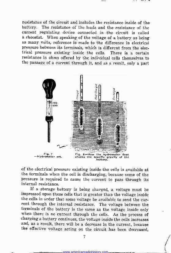
TESTING CELLS WITH A HYDROMETER By drawing some of the electrolyte out of a cell in the bat-
tery into a glass barrel, its specific gravity can be measured. The glass float inside the hydrometer barrel will float in the liquid, the figures on the stem of the float which appear on a level with the surface of the electrolyte indicate the specific gravity of the latter. See Figure 7.
The electrolyte from the cell of a fully charged battery should have a specific gravity reading between 1275 and 1300.* The three cells composing a 6 -volt storage battery are isolated from each other, therefore, use the hydrometer on all three, not just one. Two of the cells might give a normal reading, when the third was undercharged. Don't overlook this fact.
If the electrolyte in one cell is low in its specific gravity reading, leave the battery on charge for a greater length of time
'The decimal point is not placed on the Hydrometer scale readings. but must be under- stood by the reader and inserted when recording readings. 1300 means 1.300.
5
www.americanradiohistory.com
and give this cell a chance to pick up; a slight excess charge will not harm the other two cells just so long as it is not continued for too long a period.
As to the lower limits, when the electrolyte drops to a specific gravity of 1.200, it is time for the battery to be recharged. It is best to start the charging even before it reaches this figure, say at 1.210. The battery is entirely discharged when the specific gravity falls to 1.150. Remember that an ordinary voltmeter reading either before or after a charge is not a suitable method for determining the condition of the battery.
Electrolyte, like most substances, expands with heat, affect- ing the hydrometer reading. To compare different hydrometer readings, therefore, the temperature should be about the same. It is a known fact that every three degrees increase in tempera- ture decreases the hydrometer reading 1 point and this fact can be used in estimating what the hydrometer reading would be at normal temperature. The normal is taken at 78 degrees Fahrenheit. If the hydrometer reading at 100 degrees is 1.270, it would be 10 points more, or 1.280 at 70 degrees. When the temperature is much above or below normal, hydrometer read- ings should be corrected for temperature. Some hydrometers are a combination hydrometer and a thermometer, showing in red ink the temperature of the electrolyte, while at the same time giving the specific gravity reading in black ink. By specific gravity is meant the relative weight of any substance compared with water as a basis.
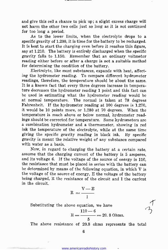
Now, in regard to charging the battery at a certain rate, assume that the charging current of the battery is 5 amperes, and its voltage 6. If the voltage of the source of energy is 110, the resistance that must be placed in series with the battery can be determined by means of the following equation, in which V is the voltage of the source of energy, E the voltage of the battery being charged, R the resistance of the circuit and I the current in the circuit.
V-E R
I
Substituting the above equation, we have 110 -6
R = = 20.8 Ohms. 5
The above resistance of 20.8 ohms represents the total
6
www.americanradiohistory.com
resistance of the circuit and includes the resistance inside of the battery. The resistance of the leads and the resistance of the current regulating device connected in the circuit is called a rheostat. When speaking of the voltage of a battery as being so many volts, reference is made to the difference in electrical pressure between its terminals, which is different from the elec- trical pressure existing inside the cells. There is a certain resistance in ohms offered by the individual cells themselves to the passage of a current through it, and as a result, only a part
Fig. 7 -Hydrometer set.
Fig. 8-How the hydrometer float checks the specific gravity of the
battery.
of the electrical pressure existing inside the cells is available at the terminals when the cell is discharging, because some of the pressure is required to cause the current to pass through its internal resistance.
If a storage battery is being charged, a voltage must be impressed upon these cells that is greater than the voltage inside the cells in order that some voltage be available to send the cur- rent through the internal resistance. The voltage between the terminals of the battery is the same as the voltage inside only when there is no current through the cells. As the process of charging a battery continues, the voltage inside the cells increases and, as a result, there will be a decrease in the current, because the effective voltage acting on the circuit has been decreased,
7
www.americanradiohistory.com

and the resistance must be decreased if it is desired to maintain the current constant.
In charging a single 6 -volt battery from a 110 -volt circuit as shown in Figure 1, the greater part of the energy supplied by the source of energy is expended in the resistance and the process is not at all efficient. The ratio of the input to the battery and the input to the resistance is the same as the ratio between the voltage over the battery and the resistance, respectively. This charging process can be made a great deal more efficient by con- necting a number of storage batteries in series, and charging them all at the same time. The total voltage over the batteries
Fig. 9-Showing how to charge a 6 -volt A battery from a 32 or 110 -volt direct current line by means of a lamp bank. Adding lamps to the bank will Increase the charge rate. Using lamps of larger wattage will also increase
the charge rate.
in this case will be much greater and a much smaller resistance will be required. It is thus seen that the value of the resistance in ohms-that is, to be connected in series, will depend entirely upon the effective voltage and current required.
CONTROL RESISTANCES
If it is desired to charge a single 6 -volt battery as was originally assumed, a very simple and inexpensive resistance may be made as follows: Obtain several porcelain lamp sockets ;
mount these sockets on a piece of board covered with asbestos, just far enough apart so that the lamps will not touch when
8
www.americanradiohistory.com

placed in the sockets. On one end of the board mount a 10 - ampere snap switch, a plug fuse block and four binding posts, and make the connections as indicated in Figures 2 and 9, using insulated wire. The charging current supplied to the battery may be regulated by screwing the lamps in or out of their respec- tive sockets. If a larger current is desired, more lamps may be connected in parallel with those already in use. The completed board may be mounted on the wall and a small shelf provided for the battery, which will give a very convenient means of charg- ing it.
[];/qRG//vG 9' BArreKY fKaH 32 voLr SsrEo!
Zee,. OawA- - USE /00 Warr L.fMro /.v PaeaLLEL -qBusr 9Y ADD/N6
NuHCCR aFLAMPS U r/e r -T
CfRRecr eire /s GOTa/NED
TN<ew Misów/rcw o.v o <rW.ycnGc.veeqm.ers Or.,ev.w.i LaeaE JE Yocr Beer -rem, Aawwvs Meow, TesSw.raa our Dueav.rec>wog Barreg.?, acme, Sra'w.wa G/neóc ow ME ¿Sear 3E An, Carrete
H BarreR RArE ABaur AHVS, Fo.e EYERy LAroP
Zr .s YELy %MPoerawr T44r M. OW; o/ rye g' B.r+TCcv aocs N -c oE ne C aebrvA 5 QCCRTCPoJ/r/<aFTE+%f 'BarrC.PY îe Poe-/T/VE Ce CNa4a/w6 Sou.eGC
Fig. 10-Shows method of wiring for charging both "A" and "B" batteries from a 32 -volt farm lighting unit.
To determine the number of amperes that will pass into the battery through a single lamp, divide the wattage of the lamp by the voltage. For example, the number of amperes that flow through a 110 -volt 60 -watt lamp is equal to 60 divided by 110 or 54/100 (.54) of an ampere, approximately 1/2 ampere. Four of these lamps in a bank would give a charging current of 2
amperes through a battery. For charging a battery from a 220 - volt circuit, proceed as for a 110 -volt circuit, but use 220 -volt lamps of twice the watts used for 110 volts if it is desired to obtain the same number of amperes.
Storage batteries may be charged from a 32 -volt farm light- ing circuit. A lamp bank of 32 -volt lamps may be used. Do not use only three or four cells of the farm lighting plant for this will unbalance the battery-that is to say, the amount of charge
9
www.americanradiohistory.com
in the cells will then be unequal and when placed on charge, some of the farm lighting cells will be charged before the others or may be overcharged. There is no objection to charging a stor- age battery while the farm lighting cells are being charged by the engine generator, but the charge rate to the battery must be watched so that it does not exceed a maximum as the farm lighting cells become charged.
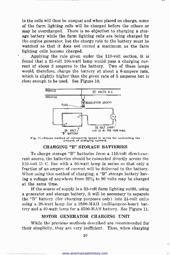
Applying the rule given under the 110 -volt section, it is found that a 32 -volt 100 -watt lamp would pass a charging cur- rent of about 3 amperes to the battery. Two of these lamps would, therefore, charge the battery at about a 6 -ampere rate, which is slightly higher than the given rate of 5 amperes but is close enough to be used. See Figure 10.
L 32 VOLT LAMP; 24 VOLT I USE 20 W. Pa 2500 M&H.
B" BATTERY
Fig. 11-Shows method of connecting lamps in series for controlling the amount of charging current.
CHARGING "B" STORAGE BATTERIES
To charge storage "B" batteries from a 110 -volt direct -cur- rent source, the batteries should be connected directly across the 110 -volt D. C. line with a 50 -watt lamp in series so that only a fraction of an ampere of current will be delivered to the battery. When using this method of charging, a "B" storage battery hav- ing a voltage of anywhere from 221/2 to 90 volts may be charged at the same time.
If the source of supply is a 32 -volt farm lighting outfit, using a generator and storage battery, it will be necessary to separate the "B" battery (for charging purposes only) into 24 -volt units using a 20 -watt lamp for a 2500 -MAH (milliampere -hour) bat- tery and a 40 -watt lamp for a 4500 -MAH battery. See Figure 11.
MOTOR GENERATOR CHARGING UNIT
While the previous methods described are recommended for their simplicity, they are very inefficient. Thus, when charging
10
www.americanradiohistory.com

III I 1 . IL
a 6 -volt battery at a 5 -ampere rate from a 110 -volt D.C. line, the power consumed by the resistances and dissipated as heat is 104 multiplied by 5 equals 520 watts while that consumed by the bat- tery is only 6 multiplied by 5 equals 30 watts. Thus, the effi- ciency of the method is only approximately 6%.
Obviously, such a wasteful procedure would be impractical commercially. An excellent method for charging batteries which is not only satisfactory for the owner who charges his own bat- teries but equally for one who finds battery charging for his neighbors a fairly lucrative side -line, consists of a motor genera- tor. An automobile generator, most of which can deliver about 15 amperes at 8 volts, is coupled or belted to about a 1/6 H.P. motor, driven from the main line. The motor is A.C. or D.C., depending upon the installation.
Fig. 12-This shows a motor -generator equipment for charging batteries.
The advantages of a motor generator charging set are : (1) Highest efficiency. (2) Quickest method of charging. (3) Longest life (no bulbs, etc.). Figure 12 illustrates the general lay-out of the complete
equipment for a motor generator installation as used in connec- tion with charging storage batteries, both for radio and automo- bile purposes. The 110 -volt A.C. source is shown in the upper left-hand corner with a snap switch (just to the right) for start- ing and stopping the motor.
Just below the snap switch is shown the proper protective fuses which will open the circuit in case there is an overload or short-circuit on the generator. The machine to the left is a motor which is directly connected by a coupling to the generator. The voltage of this generator may be varied from about 4 or 5 volts up to a maximum of 35 or 40 volts by means of a field rheostat.
11
www.americanradiohistory.com

In the upper right-hand corner of the figure is shown a double reading ammeter and just below it is a fuse block, in which may be inserted different size fuses according to the charging current that is to be used. In case the 110 -volt power should be accidentally cut off, the motor generator set will stop and the battery will discharge back to the generator armature causing a high value of current to flow in the circuit due to the very low resistance of the armature. The fuses or a circuit breaker will open the circuit under these conditions and avoid the battery being discharged due to this occurrence.
Its only disadvantage is the higher initial cost but if the battery charging is to be considered as a source of income, this factor dwindles. The size of the unit must, of course, be in- creased if the total charging load is in excess of the output of the generator.
A. C. CHARGERS Rectifiers for Charging Storage Batteries
In many instances where only alternating current is avail- able, the expense of the installation of a motor generator set and switchboard for charging purposes is not justified and other means must be provided. Since only direct current is suitable for charging, the alternating current must be changed to direct current before it passes through the battery. This changing of the alternating current to direct current is known as rectification and the apparatus or instrument by which the conversion is made is known as a rectifier. // t-
An alternating current is orpe that is constantly changing in intensity and reverses its direction of flow periodically. Graphically, the fluctuation of an alternating current with time may be represented by the wave of Figure 13, which is drawn for a 25 -cycle current. In this figure, the distance horizontally from the point marked "O" represents time after closing the cir- cuit. The distance from this line to the wave represents the intensity and direction of the current flow at any particular instant. Thus at the instant of closing the circuit, the current is zero, 1/200 of a second later, the value of the current is repre- sented by the line a -b in the positive direction. This means that in Figure 14 the current at this instance is flowing from A to B. After an interval of 1/100 of a second, the current is represented by the line c -d still in the positive direction. After an interval of 1/50 of a second, the current is again zero and during the
12
www.americanradiohistory.com
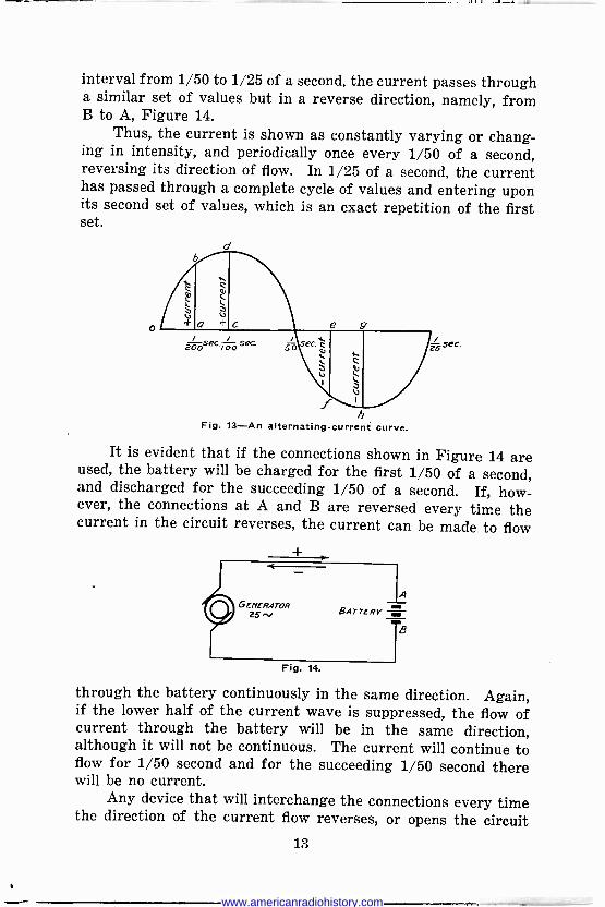
interval from 1/50 to 1/25 of a second, the current passes through a similar set of values but in a reverse direction, namely, from B to A, Figure 14.
Thus, the current is shown as constantly varying or chang- ing in intensity, and periodically once every 1/50 of a second, reversing its direction of flow. In 1/25 of a second, the current has passed through a complete cycle of values and entering upon its second set of values, which is an exact repetition of the first set.
Fig. 13-An alternating -current curve.
It is evident that if the connections shown in Figure 14 are used, the battery will be charged for the first 1/50 of a second, and discharged for the succeeding 1/50 of a second. If, how- ever, the connections at A and B are reversed every time the current in the circuit reverses, the current can be made to flow
Fig. 14.
through the battery continuously in the same direction. Again, if the lower half of the current wave is suppressed, the flow of current through the battery will be in the same direction, although it will not be continuous. The current will continue to flow for 1/50 second and for the succeeding 1/50 second there will be no current.
Any device that will interchange the connections every time the direction of the current flow reverses, or opens the circuit
13
www.americanradiohistory.com
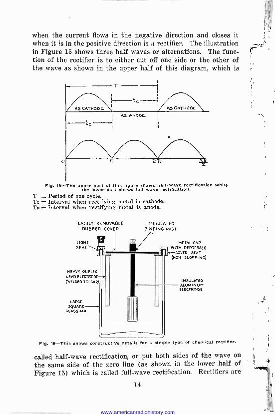
when the current flows in the negative direction and closes it when it is in the positive direction is a rectifier. The illustration in Figure 15 shows three half waves or alternations. The func- tion of the rectifier is to either cut off one side or the other of the wave as shown in the upper half of this diagram, which is
AS CATHODE_
T
ta
AS CATHOOE
I AS ANODE.
t c I
Fig. 15-The upper part of this figure shows half -wave rectification while the lower part shows full -wave rectification.
T = Period of one cycle. Tc = Interval when rectifying metal is cathode. Ta = Interval when rectifying metal is anode.
EASILY REMOVABLE RUBBER COVER
TIGHT SEAL
HEAVY DUPLEX LEAD ELECTRODE (WELDED TO CAP)
LARGE SQUARE
GLASS JAR
INSULATED BINDING POST
METAL CAP WITH DEPRESSED
4 --CAVER SEAT (NON SLOPPING)
INSULATED ALUMINUM E LECTRO 0 E
Fig. 16-This shows constructive details for a simple type of chemical rectifier.
called half -wave rectification, or put both sides of the wave on
the same side of the zero line (as shown in the lower half of Figure 15) which is called full -wave rectification. Rectifiers are
14
www.americanradiohistory.com

Ill .1 . Ill
of many types, but most of them fall under one of three classes: A. Chemical Rectifiers. s 7- B. Mechanical Rectifiers. C. Electron Rectifiers. First, we have what is known as the electrolytic rectifier,
wherein two plates of dissimilar metals are immersed in a solu- tion and the entire arrangement is so made that current can only pass through it in one direction, whereby a rectifying action is obtained. Second, is the mechanical (vibrator) rectifier. This
110VOLTALTERNATING CURRENT LINE
40 WATT ALUMINUM LEAD LAMP ELECTRODE ELECTRODE
f eat RECTIFIER
POSITIVE -
REGULAR LAMP SOCKET
OR BASE RECEPTACLE
ds . _ -rl Ì ffllilt i I
lt rí !Pi II
-NEGATIVE
8 STORAGE BATTERY 24 VOLTS OR 48 VOLTS
Fig. 17-This illustrates the use of half -wave rectification by use of one rectifier with a lamp in series to control the amount of charging current.
device may be connected in a circuit; when an alternating current is applied to the input circuit a pulsating direct current will be delivered by the output. The third type to be considered is that using a vacuum tube rectifying the alternating current. Let us now consider in detail these three types of chargers or rectifiers as they are often called.
DESCRIPTION OF A CHEMICAL RECTIFIER The chemical rectifier is the simplest in construction, con-
sisting of a positive plate of aluminum or tantalum and a nega- tive plate of lead immersed in a saturated solution of borax, or a solution of ammonium phosphate as shown in Figure 16. (Use
15
www.americanradiohistory.com

3/4 of a pound of ammonium phosphate to one gallon of water.) Before this type of rectifier can be put into use, the aluminum plate must be formed. This can be done by placing a 100 -watt lamp in series with the rectifier cell across a 110 -volt line. The deposit which forms on the aluminum plate that is responsible for the rectifying action permits the current to flow through it in one direction, but checks it in the other, thus giving half -wave rectification, as shown in Figure 15.
By connecting two cells as shown in Figure 18, it is possible to get full -wave rectification for charging a "B" battery and in the case of an "A" battery where the current is much larger, the rectifiers may be connected in parallel as shown in Figure 19. Since this type of charger cannot handle a heavy load without excessive heating and consequent poor rectification and lower effi- ciency, it cannot charge an "A" battery as quickly as the other types, but it is an excellent trickle charger for the "A" battery and a good "B" battery charger.
TRICKLE CHARGERS
A trickle charger is a device designed to maintain an "A" battery in a continual state of full charge. This charger is con- nected to the "A" battery through a special master switch that turns on the charger by the same operation which turns off the receiving set. Since this switch turns the set on and the charger off at one operation and turns the set off and the charger on at another single operation, the battery is being charged whenever the set is not in use.
Trickle chargers are designed to give a very low charging rate to the battery and generally not more than 1/4 to 1/2 of an ampere. This charging rate is sufficient to keep the "A" battery fully charged at all times and yet is too low in amperage to harm the "A" battery even though the charge continues indefinitely. A
trickle charging unit consists of a transformer for reducing the supply line voltage and a rectifier of the electrolytic, dry or bulb type. Such a unit is often built in one housing with a specially designed storage battery of small ampere hour capacity, but with an extra large space for the rectifier. Such a battery will handle an ordinary receiving set because it is charged immediately after each period of discharge.
Some trickle chargers on the market are provided with a regulating resistance by means of which the charging rate may be varied to care for the requirements of the battery.
16
www.americanradiohistory.com
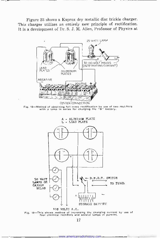
Figure 23 shows a Kuprox dry metallic disc trickle charger. This charger utilizes an entirely new principle of rectification. It is a development of Dr. S. J. M. Allen, Professor of Physics at
L AD ATES
GATIVE
ALUMINUM PLATES
f
25 -WATT LAMP
TO 110 -VOLT MAINS ALTERNATING CURRENT)
CENTER CONNECTION Fig. 18-Method of obtaining full -wave rectification by use of two rectifiers
with a lamp in series for charging the "B" battery.
50 WATT LAMPS OR CARBON
BULBS
A - ALUMINUM PLATE L - LEAD PLATE
V 110 VOLTC A.C.
Flg. 19-This shows method of increasing the charging current by use of four chemical rectifiers and several lamps in parallel.
D.P.D.T. SWITCR o >
o TO TUBI
IIII 1141 it STORAGE BATTERY
17
www.americanradiohistory.com
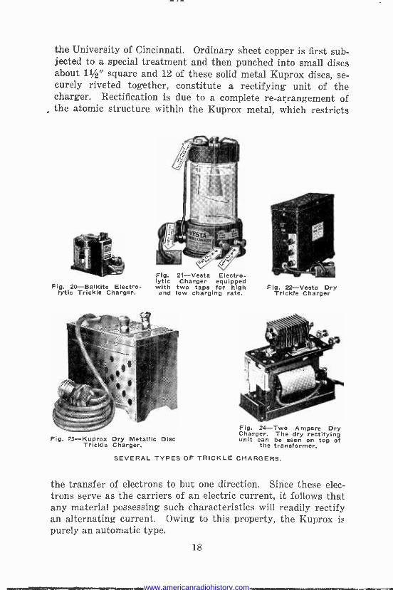
the University of Cincinnati. Ordinary sheet copper is first sub- jected to a special treatment and then punched into small discs about 11/2" square and 12 of these solid metal Kuprox discs, se- curely riveted together, constitute a rectifying unit of the charger. Rectification is due to a complete re -arrangement of the atomic structure within the Kuprox metal, which restricts
Fig. 21-Vesta Electro- lyticFig. 2Balkite Electro.
Charger equipped with two taps for high
lytic Trickle Charger. and low charging rate.
Fig. 23-Kuprox Dry Metallic Disc Trickle Charger.
Fig. 22-Vesta Dry Trickle Charger
Fig. 24-Two Ampere Dry Charger. The dry rectifying unit can be seen on top of
the transformer.
SEVERAL TYPES OF TRICKLE CHARGERS.
the transfer of electrons to but one direction. Sirice these elec- trons serve as the carriers of an electric current, it follows that any material possessing such characteristics will readily rectify an alternating current. Owing to this property, the Kuprox is purely an automatic type.
18
www.americanradiohistory.com

DESCRIPTION OF VIBRATING RECTIFIERS The vibrating rectifier consists of a contactor operated in
synchronism with the alternating current to be rectified. When .4 C. INPUT
P
SPRING Fig. 25-Circuit diagram of a vibrating battery
charger (Half -wave Type).
q,L INPUT
¡ ¡ P Q_[y `QQQQQQQi
COHpEnsERJ 1`-canoc7(5ER
AMMETER
T TO BATTERY'
Fig. 26-Circuit diagram of a vibrating battery charger (Full -wave Type).
the contactor is allowed to make and break the circuit at the proper point of the wave, pulsations of current occur in the same direction ; with a single contact as shown in Figure 25, half -wave
19
www.americanradiohistory.com

rectification is obtained and with a double contact as shown in Figure 26, full -wave rectification is obtained. When the current from the supply line is of the correct polarity to charge the bat- tery in Figure 25, the contacts close and the current flows through
Fig 27-Kodel Home -Charger. Vibrating Type. This particular instrument is so constructed that it can be used for both "A" and "B" battery charging. For charg- ing "B" batteries, the fuse plug is removed. and the suitahle size incandescent bulb inserted in the socket.
Fig. 28-This shows a vibrating reed type of rectifier assembled in its cabinet with the doer open.
the battery, but when the supply line reverses its polarity, the contacts open and the battery cannot be discharged. On this diagram, taps are shown for charging the battery at several voltages.
The vibrator rectifier circuit shown in Figure 26 is built in such a way that the connections of the charging line to the bat -
20
www.americanradiohistory.com

tery are automatically reversed with the reversal of current flow
in the power line. This reversal in the rectifier is brought about by a combination of two electromagnets and a spring. When the current flowing in the power line passes through the A.C. elec- tromagnet in one direction, this electromagnet attracts one end of the D.C. electromagnet. When the current in the power line reverses, the other end of the D.C. electromagnet is attracted. When the magnets are acting together, they overcome the tension of the spring and close the vibrator contact permanently, charg-
Fig. 29-Illustrates the small and large size of tubes for rectifying
purposes.
Fig. 30-General appearance of a commercial one tube rectifier with
two sides and top removed.
ing current can then flow through the battery. At the instant of
reversal of current flow, the magnets balance each other and the spring opens the contact ; a reversal of current cannot then flow
through the battery and discharge it. Some vibrating rectifiers have a spring whose tension must
be adjusted in such a manner as to vibrate in step with the alter- nations of the power or supply lines. With this adjustment cor- rectly made, the spring will open the circuit at the proper time. The spring adjustment on vibrating chargers is sometimes critical
21
www.americanradiohistory.com

and the least movement of the regulating screw one way or the other will start or stop the charge. Other chargers of the same type are not at all critical and are easily handled. The adjust- ment should be made to give the greatest possible current in amperes without making the vibrator contact spark excessively. The vibrating contact rectifier is fundamentally a vibrating reed, whose frequency is the same as that of the current to be rectified, carrying a contact which engages the second contact for each vibration of the reed. The contacts complete a circuit from the secondary of a step-down transformer through the storage battery each time they touch.
The armature is polarized either by using a permanent mag- net or by using an electromagnet energized by the battery being charged. The result of using a polarized armature whose period of vibration is the same as the frequency of the A.C. line is that
Fig. 31-Wiring diagram using one tube for half -wave rectification. The filament current is supplied by low voltage winding operated from the A. C. source.
the contacts touch at the point of each succeeding cycle and remain in contact for a portion of the half -wave so that the resultant current through the battery is shown by Figure 15.
DESCRIPTION OF THE ELECTRON RECTIFIER The electron rectifier utilizes the phenomenon of electron
emission from a hot tungsten filament. If such a filament be made to serve as one electrode in a highly evacuated tube along with a cold electrode having a positive potential with respect to the filament, electrons will flow from the hot filament to the cold electrode. If the cold electrode or plate remains negative with respect to the filament, the electrons emitted will be repelled by the negative plate and no current will flow. If an alternating potential be applied, electrons will flow only during the half cycle when the plate is positive. An alternating current is thereby rectified. Figure 31 shows the connections of a half -wave recti-
22
www.americanradiohistory.com
fier using an electron tube in its simple form. The equipment in
this case consists of the bulb B with a tungsten filament F and a
graphite plate A, transformer T for exciting the filament, rheo- stat R and the load which is shown as the storage battery.
Assuming an instant when the side C of the alternating cur- rent supply is positive, the current follows the direction of the arrows through the load, rheostat and bulb, and back to the opposite side of the alternating current line. A certain amount
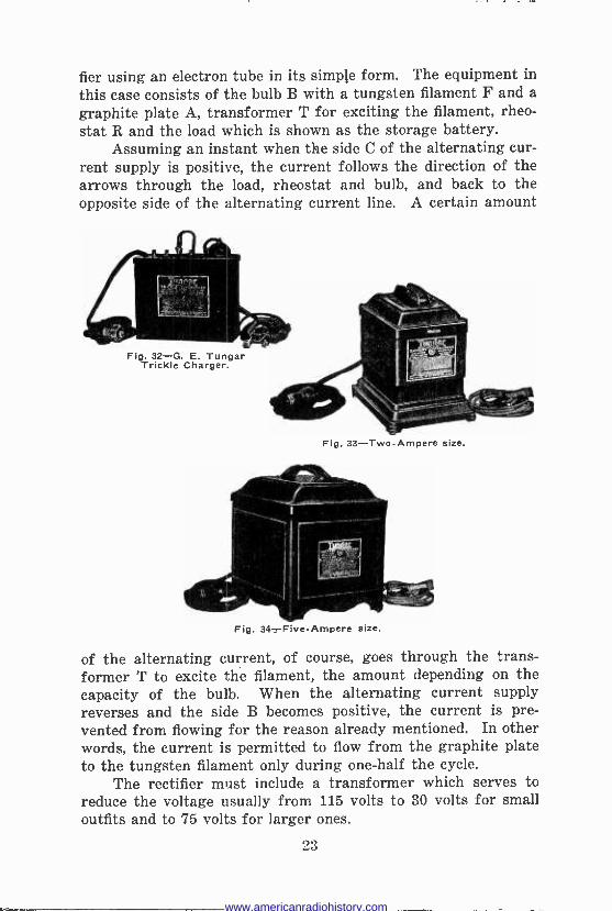
Fig. 32-G. E. Tungar Trickle Charger.
Fig. 33-Two-Ampere size.
Fig. 34 -Five -Ampere size.
of the alternating current, of course, goes through the trans- former T to excite the filament, the amount depending on the capacity of the bulb. When the alternating current supply reverses and the side B becomes positive, the current is pre- vented from flowing for the reason already mentioned. In other words, the current is permitted to flow from the graphite plate to the tungsten filament only during one-half the cycle.
The rectifier must include a transformer which serves to reduce the voltage usually from 115 volts to 30 volts for small outfits and to 75 volts for larger ones.
23
www.americanradiohistory.com

The electron rectifying tube used for battery charging resembles a large incandescent lamp with three terminals. See Figure 29. The elements are enclosed in a round glass bulb filled with argon, an inert gas. The trade name "tungar" is com- posed of the combination of the first syllables of "tungsten" and "argon." The bulbs are made in two sizes. The first charges a 6 -volt battery at about 2 amperes, the latter at about 5 amperes. The smaller tube is mounted on a standard Edison screw base while the larger fits in a Mogul socket such as is used for extra large electric lights. The construction is similar in both tubes, for the filament connections come out through the Edison base, while the plate connection is brought out at the top of the tube.
A BATTERY CHARGING HOOK-UP. Fig. 35-The wiring for the switch, the charger and the battery, from the lighting plug to the receiver in the quick change -over arrangement for battery and charger
which is described above.
When in normal operation, there is a blue haze between the plate and filament in addition to the light from the filament and the plate will become just barely a dull red.
By using a transformer with the secondary coil tapped in the middle and using two tubes, full -wave rectification may be secured which will double the charging rate. The actual appearance of a complete rectifier unit using one tube and the two sides removed and the top cover lifted up is shown in Figure 30. Rectifiers are manufactured by the General Electric Company in three styles, all of the half -wave type, with different current and volt- age capacities. All three types are for 115 volts, 60 cycle circuits.
CONSTRUCTION OF A TUNGAR CHARGER USING A 5 -AMPERE TUBE
To construct the core, 230 pieces of .014" core iron will be required. These pieces should be cut L shaped so that the legs
24
www.americanradiohistory.com
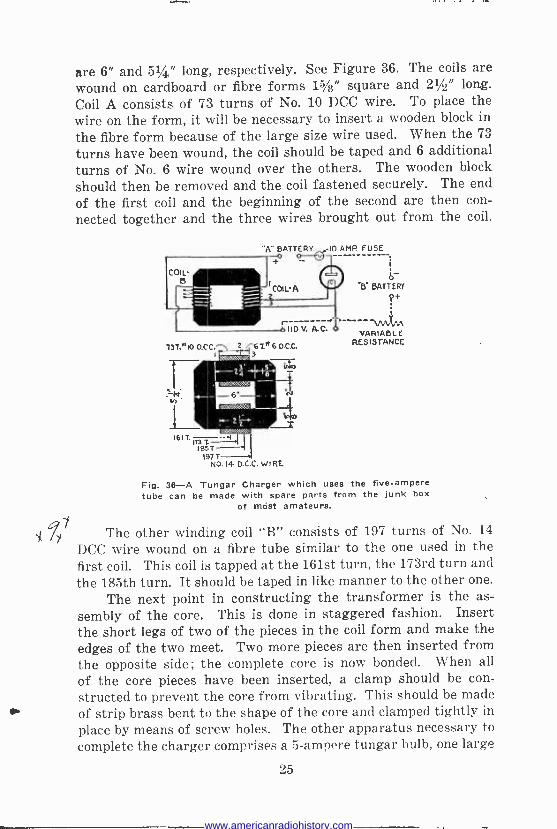
are 6" and 51/4" long, respectively. See Figure 36. The coils are wound on cardboard or fibre forms 15/8" square and 21/2" long.
Coil A consists of 73 turns of No. 10 DCC wire. To place the wire on the form, it will be necessary to insert a wooden block in
the fibre form because of the large size wire used. When the 73
turns have been wound, the coil should be taped and 6 additional turns of No. 6 wire wound over the others. The wooden block should then be removed and the coil fastened securely. The end
of the first coil and the beginning of the second are then con- nected together and the three wires brought out from the coil.
COIL- a
i3T.a10 D.CC. 2 111111
r --HO V. A. C.
67» 6 D.C.C. 3
24 i B . WO':ClE.yl
re:::-_ 2 Z -
61T.
MST 197 T
NO.14 D.C.C. WIRE
"A" BATTERY _ 10 AMP FUSE
9 BATTERY
VARIABLE RESISTANCE
Fig. 36-A Tungar Charger which uses the five -ampere tube can be made with spare parts from the junk box
of mist amateurs.
The other winding coil "B" consists of 197 turns of No. 14
DCC wire wound on a fibre tube similar to the one used in the first coil. This coil is tapped at the 161st turn, the 173rd turn and the 185th turn. It should be taped in like manner to the other one.
The next point in constructing the transformer is the as- sembly of the core. This is done in staggered fashion. Insert the short legs of two of the pieces in the coil form and make the edges of the two meet. Two more pieces are then inserted from the opposite side; the complete core is now bonded. When all
of the core pieces have been inserted, a clamp should be con-
structed to prevent the core from vibrating. This should be made of strip brass bent to the shape of the core and clamped tightly in
place by means of screw holes. The other apparatus necessary to complete the charger comprises a 5 -ampere tungar bulb, one large
25
www.americanradiohistory.com

standard lamp socket and a 10 -ampere fuse. This apparatus should be connected as shown in the diagram. The charger is
IN then ready for operation. If it is desired to use it for charging "B" batteries, a 50 -watt resistor capable of carrying at least
Na1/2
ampere is connected as shown in the dotted lines. A stor- ge "B" battery of 50 volts can be charged in this way. The
complete charger can be installed in a metal container if desired. If this is done, care should be taken to insulate all the apparatus from the container so that no short, circuits can occur. The variable resistor and the switches can be mounted on one of the sides of the can, if desired, so that they can be easily varied.
Fig. 37-Half-wave Charger. Fig. 38-Full-wave Charger.
Fig. 39-G. E. Tungar 4 -Battery Charger.
When the charger has been assembled and connected to the battery for charging, inspection should be made of the initial performance. When charging a 6 -volt battery the charging rate should be 5 amperes. On a 12 -volt battery the rate should be about 21/2 amperes.
Figures 37 and 38 show a half -wave and full -wave charger manufactured by the National Company of Cambridge, Mass. Figure 37 employs one Raytheon rectifier tube (cartridge Unit)
26
www.americanradiohistory.com
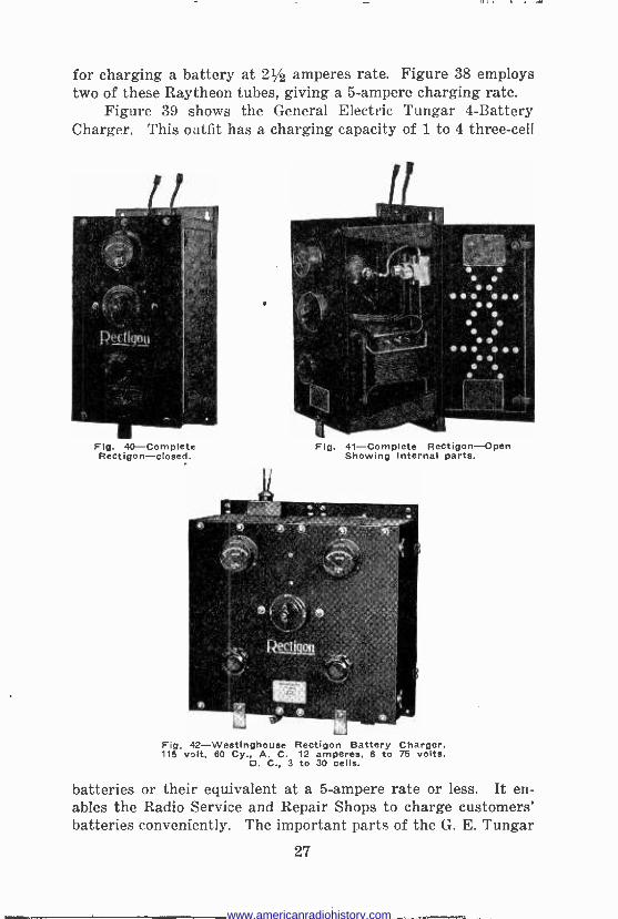
for charging a battery at 21/4 amperes rate. Figure 38 employs two of these Raytheon tubes, giving a 5 -ampere charging rate.
Figure 39 shows the General Electric Tungar 4 -Battery Charger. This outfit has a charging capacity of 1 to 4 three -cell
Flg. 40-Complete Rectigon-closed.
Fig. 41-Complete Rectigon-Open Showing internal parts.
Fig, 42-Westinghouse Rectigon Battery Charger, 115 volt, 60 Cy., A. C. 12 amperes, 6 to 75 volts,
D. C., 3 to 30 cells.
batteries or their equivalent at a 5 -ampere rate or less. It en- ables the Radio Service and Repair Shops to charge customers' batteries conveniently. The important parts of the G. E. Tungar
27
www.americanradiohistory.com

are an insulating transformer, a regulating coil and a rectifying bulb. This unit is very simple to operate. To charge batteries, simply connect them in series with the Tungar and turn the handle on the front panel until the ammeter indicates the exact current desired. The handle serves the double purpose of turning
Fig. 43-Typical Installation of 6 -ampere, 75 -volt Rectigon suitable for small battery service station
on the A.C. supply and of regulating the current. This tungar is particularly adapted to overnight charging without any atten- tion. It delivers a steady flow of current which insures proper charging of the batteries.
Figures 40 and 41 show Westinghouse Electric Company 6 -ampere 75 -volt Rectigon Outfits. This charger is very suitable for battery service stations where a number of batteries are to be charged. All parts are mounted in a steel case and are readily accessible through a hinged door on the side to permit replace- ment of fuse or bulb. Leads from the alternating current and
28
4
www.americanradiohistory.com

Ill I . 1 . Y - --
direct current are brought out at the top and bottom of the Rectigon and plainly marked. This outfit can be easily installed by placing it on a bench or mounted on the wall by means of a special mounting bracket, which is furnished with the outfit. There are only four wires to be connected, and the connections are clearly indicated.
Figure 42 shows a Westinghouse Twin Six Rectigon for large Service Stations. This 12 -ampere 75 -volt Rectigon is a simple and very efficient battery charging set for use by large Battery Service Stations which have a large volume of battery business. Such a unit is also to be recommended for use in small Service Stations where a higher charging rate is required than that obtained from the smaller 6 -ampere 75 -volt Rectigon outfit. Although this outfit is primarily designed to charge from 3 to 30 lead cells at a 12 -ampere rate, nevertheless the construction per- mits of at least 3 possible combinations of connections for charg- ing batteries.
Figure 43 shows a typical installation of a 6 -ampere 75 -volt Rectigon Outfit for a Battery Service Station.
TEST QUESTIONS Number your Answer Sheet 27-2 and add your Student Number.
1. Describe the salt water method of determining the positive terminal of a circuit.
2. What should be used for testing the condition of a storage battery ?
3. What should be the total resistance used when charging a 6 -volt battery from the 110 -volt D.C. lighting system at a 5 ampere rate ?
4. What is a rectifier? 5. Name the three classes of rectifiers. 6. For what type of charging is the chemical rectifier best
adapted ?
7. Draw a circuit diagram illustrating a one-half wave me- chanical rectifier.
8. Draw a diagram showing the connections of a half -wave electron tube rectifier.
9. What size and how many turns of wire are in the coil "B" of the transformer used in the construction of the 5 -ampere charger described in this lesson?
10. What additional apparatus is added to the Tungar charger described on page 25 if it is desired to charge "B" batteries?
29
www.americanradiohistory.com
www.americanradiohistory.com