Embed Size (px)
Citation preview

Theodore E. Bo.e Editor
J. F. Thompson Associate Editor
J. B. Straughn Technical Editor
L. L. Menee Editor Emeritus
Editorial
NRI NEWS Vol. 18, No. 10 August -September, 1959
Published every other month by the National Radio Institute, 3938 Wisconsin Ave., N.W., Washington 16, D. C. Subscription $1.00 a year. Printed in U.S.A. Second class postage paid at Washington, D. C.
Harvest Time It means a lot to the farmer; harvest time.
It is toward the harvest when he will receive the reward for his labors, that he works and sweats in the broiling fields all summer long.
And his reward, the abundance of his crops will be in exact proportion to his labor in planting and caring for his fields.
There are other "harvests" than those of crops. In fact, there are "harvests"-or their absence-throughout the lives of everyone of us. Just as with the farmer, the abundance of our crops is in exact proportion to our effort; we "reap as we sow." If the farmer is lazy, careless, and indifferent in sowing and tending his fields, at harvest his crops will be poor and scanty. So, too, with us. If we are lazy, careless, and indifferent in our ef- forts, our "crops"-our rewards will be poor and scanty.
We all know this to be true. We all know that you can't get something for nothing, that you can't command rewards in return for poor or little effort. Yet many of us forget it at times or have become so lazy through habit that we can't make an "about face" even when we remember to do it.
It's therefore up to you and to me to keep it ever before us that we are going to "reap as we sow," and that we must "sow" to the very best of our ability in order to earn a harvest worth having.
J. E. SMITH, Founder
Ever wonder what goes into the design, development, and general engineering of a new test instrument? Our feature article this issue-beginning on page eight will give you a step-by-step look at how a new oscilloscope kit was de- veloped. We think you'll like it!
Editor
Manufacturer's Literature Promotes
Sales and Service By J. Schek
NRI Consulant
HAVE YOU RECENTLY encountered a very late model set whose unfamiliar re- mote control tuner mechanism or tube types made you wish you had the manu- facturer's data handy?
Does your spare or full-time service busi- ness need better customer relations, low- cost advertising ideas or sparkling show - cards?
Would you like to have the latest circuit information straight from the manufactur- er's development and service laboratory?
Can you use help in licking those tough service problems?
If these questions point up your needs, then here's a good way to go about getting the answers. But first a word about the sponsors.
In a continuing effort to professionally raise the technical and business ability of servicemen, various manufacturers pre- pare and publish technical literature which is issued regularly to those who are on their mailing lists.
These technical news bulletins show how new applications of basic receiver circuits operate; how to get and use manufactur- er's inexpensive sales -promotion aids to pep -up business and keep it expanding; when and where technical meetings are to be held, and most important, direct contact is established with the manufac- turers and distributors service depart- ments so that current servicing and cir- cuit information will be received on a regular basis.
Some manufacturers make their technical literature available at no cost. Others will
(Continued on page two)

21/2 Billion Spent for Radio-TV
Repairs In 1958
Television Digest magazine reported re- cently the nation's 1958 bill for home elec- tronic repair and installation was $2.49
billion. The purchase of new sets in the same period totalled about $1.9 billion. In other words, the public is spending rough- ly 25% more each year for repairs than it does to buy new sets. TV repair and in- stallation accounts for most of the annual expenditure.
Manufacturer's Literature . . .
(From page one)
make a nominal charge for their bulletins and circuit data. Still others will send their service news at no cost but with a charge for service manuals.
Whatever plan is used, every serviceman will benefit from the technical material that is made available by the individual arrangements.
When you write to any of the following manufacturers, indicate your professional status by including your business card and typing your request on your business sta- tionery-if possible. Let them know that you are a graduate or advanced student of the National Radio Institute and are ac- tively engaged in either full time or spare time service work.
A model letter can go something like this: "I am now actively engaged in full- (or part) time radio and television service work, having received my technical train- ing from the National Radio Institute.
I am very interested in regularly receiv- ing your Technical News publication and also any service data you supply for your receivers.
Where there is an annual fee for furnish- ing this set data and diagrams, please send me your regular subscription blank or order form.
I appreciate your efforts to provide tech- nical and service information that will in- crease my ability to do a professional job in obtaining maximum receiver perform- ance."
Although most manufacturers will accept your application directly at their home of- fice the Philco Factory -Supervised Service Plan operates primarily through the local Philco Distributor. That is, application forms to join this particular manufactur- ers service plan are available at the Dis- tributor.
To locate the Philco-Distributor in your area if you do not already have this in-
Page Two
n r i
formation consult your telephone business directory, parts suppliers or a large Philco Dealer.
If you cannot get in contact with your Philco Distributor, then write directly to Philco Service Headquarters, 2nd and Westmoreland Sts., Philadelphia 42, Pa. Ask for application forms to join the Phil - co Factory -Supervised Service.
I am confident that your service business will benefit in every way by using the technical and sales help offered in the manufacturers literature.
Aerovox Corp. 740 Belleville Ave. New Bedford, Mass.
Cornell-Dubilier Electric Corp. South Plainfield New Jersey
Magnavox Co. 2131 Beuter Rd. Fort Wayne 4, Ind.
Mr. Richard A. Phillips, Editor Philco Service Technician PFSS Headquarters 2nd and Westmoreland Sts. Philadelphia 40, Penna.
Sylvania Service Digest Service Department Sylvania Home Electronics 700 Ellicott St. Batavia, New York
Mr. William Prusinowski, Editor The Motorola Service News, Motorola, Inc. 4545 West Augusta Boulevard Chicago 51, Ill.
Mr. Harvey Slovick, Editor RCA Service News RCA Electron Tube Division Harrison, N. J.
Mr. R. G. Kempton, Editor Techni-Talk Electronics Components Division General Electric Schenectady 5, N. Y.
n r i
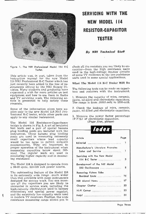
Figure 1. The NRI Professional Model 114 R -C Tester.
This article was, in part, taken from the instruction manual for the new Model 114 NRI Professional R -C Tester which has just recently been added to the line of in- struments offered by the NRI Supply Di- vision. Many students and graduates have expressed a wish for more articles on test equipment and how to use them in Radio and TV servicing work. The following ar- ticle is presented to help satisfy these requests.
Some of the information given here ap- plies only to the new Model 114 NRI Pro- fessional R -C tester, while other parts can apply to any similar instrument.
The Model 114 Resistance -Capacitance bridge is shown in Fig. 1. A set of insulated test leads and a pair of special banana plug binding posts are included with the instrument. These banana plug binding posts are used in measuring extremely small capacitors where lead capacity would be too large to permit accurate measurements. They are important to proper operation of the instrument when measuring capacities below about 500- mmf. The regular leads are used in measuring higher capacity and in measur- ing resistance.
The Model 114 is designed to operate from a 50-60 cycle, 110-120 volt power source.
The outstanding feature of the Model 114 is its extremely wide range-much wider than that available with most instruments designed for service work. You can meas- ure all the capacitors you are likely to encounter in service work, including the high -capacity electrolytics used in battery eliminators and special power supplies, and the extremely low -capacity units used in modern TV receivers. Further, the wide resistance measuring range allows you to
SERVICING WITH THE
NEW MODEL 114
RESISTOR -CAPACITOR
TESTER
By NRI Technical Staff
check all the resistors you are likely to en- counter-from the high resistance units used in the high -voltage doubler circuits of some TV receivers to the low -resistance units used in some special applications.
What The Model 114 R -C Tester Will Do
The following tests can be made on capaci- tors and resistors with the instrument.
1. Measure the capacity of mica, ceramic, paper, oil -filled and electrolytic capacitors. The range is from .00001-mfd to 1500-mfd.
2. Check the leakage of mica, ceramic, paper, oil -filled and electrolytic capacitors.
3. Measure the power factor percentage (P.F.%) of electrolytic capacitors.
(Page four, please)
Index Article Page
Editorial 1
Manufacturer's literature Promotes
Sales and Service 1
Servicing with the New Model
114 R -C Tester 3
Development of the NRI Model
250 Oscilloscope 8
Removing Picture Tube
Residual Spots 16
NRI Alumni News 17
Chapter Chatter 20
Hi-Fi Corner 25
Helpl 31
Page Three
4. Measure the ohmic value of resistors. The range is from 1 -ohm to 150-megohms.
How a Resistance Bridge Works
The operation of the bridge circuit is im- portant both to help you understand the instrument and to help you use it more effectively. Also, it might be necessary for you to service an R -C bridge at some time in the future and this knowledge is sure to prove useful then.
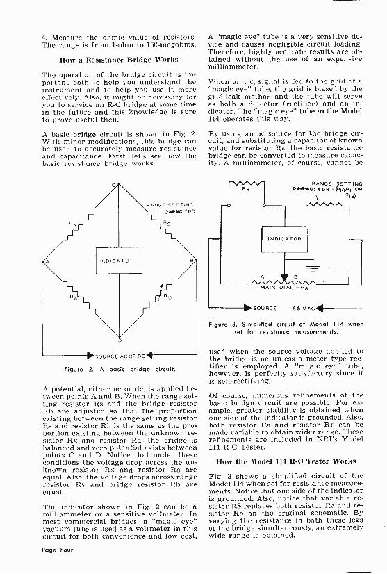
A basic bridge circuit is shown in Fig. 2. With minor modifications, this bridge can be used to accurately measure resistance and capacitance. First, let's see how the basic resistance bridge works.
RANGE SET TING
G*OACfTOR
INDICATOR
>SOURCE ACOR DC,
RS
Figure 2. A basic bridge circuit.
A potential, either ac or dc, is applied be- tween points A and B. When the range set- ting resistor Rs and the bridge resistor Rb are adjusted so that the proportion existing between the range setting resistor Rs and resistor Rb is the same as the pro- portion existing between the unknown re- sistor Rx and resistor Ra, the bridge is balanced and zero potential exists between points C and D. Notice that under these conditions the voltage drop across the un- known resistor Rx and resistor Ra are equal. Also, the voltage drops across range resistor Rs and bridge resistor Rb are equal.
The indicator shown in Fig. 2 can be a milliammeter or a sensitive voltmeter. In most commercial bridges, a "magic eye" vacuum tube is used as a voltmeter in this circuit for both convenience and low cost.
A "magic eye" tube is a very sensitive de- vice and causes negligible circuit loading. Therefore, highly accurate results are ob- tained without the use of an expensive milliammeter.
When an a.c. signal is fed to the grid of a "magic eye" tube, the grid is biased by the grid -leak method and the tube will serve as both a detector (rectifier) and an in- dicator. The "magic eye" tube in the Model 114 operates this way.
By using an ac source for the bridge cir- cuit, and substituting a capacitor of known value for resistor Rs, the basic resistance bridge can be converted to measure capac- ity. A milliammeter, of course, cannot be
RANGE SETTING CAPACITOR -eRIPRII OR
RI2)
MAIN DIAL -R8
SOURCE 55VAC
Figure 3. Simplified circuit of Model 114 when set for resistance measurements.
used when the source voltage applied to the bridge is ac unless a meter type rec- tifier is employed. A "magic eye" tube, however, is perfectly satisfactory since it is self -rectifying,
Of course, numerous refinements of the basic bridge circuit are possible. For ex- ample, greater stability is obtained when one side of the indicator is grounded. Also, both resistor Ra and resistor Rb can be made variable to obtain wider range. These refinements are included in NRI's Model 114 R -C Tester.
How the Model 114 R -C Tester Works
Fig. 3 shows a simplified circuit of the Model 114 when set for resistance measure- ments. Notice that one side of the indicator is grounded. Also, notice that variable re- sistor 118 replaces both resistor Ra and re- sistor Rb on the original schematic. By varying the resistance in both these legs of the bridge simultaneously, an extremely wide range is obtained.
Page Four

RANGE SETTING CAPACITOR (C6ORC-
INDICATOR
A B
MAIN DIAL - R6
SOURCE 55V. AC
Figure 4. Simplified schematic of Model 114 when set for capacity measurements.
The range setting resistors in the instru- ment are R10, R11, and R12. By switching the correct resistor into the circuit, the various ranges are obtained.
When the SELECTOR switch is set to the 1.8 Meg. -150 Meg. position ("Extended" range), range setting resistor R12 is still used but an extra resistor (R9) is switched into the circuit between section B of re- sistor R8 and the 55 -volt ac source. This increases the range in the instrument so that very high resistance values can be measured. R9 is shown in Figure 7.
Fig. 4 shows a simplified schematic of the instrument when it is set for capacity measurements on the .00001-.005 mfd range or the .001-.5 mfd range. Notice that a capacitor, instead of a resistor, is used in one leg of the bridge. In the instrument itself, capacitor C6 or C7 is used in this application. On the two highest capacity ranges, 18-1500 mfd and 0.1-50 mfd, the circuit is changed slightly so that a resis- tor is switched in series between the range setting capacitor and the indicator. This variable resistor is the POWER FACTOR control on the panel of the instrument. This extra control allows you to balance out the unavoidable internal resistance of an electrolytic capacitor and thereby de- termine the power factor. The circuit is as shown in Fig. 5 when the instrument is set to the two highest capacity ranges. Both resistor R8 and the POWER FACTOR control must be adjusted to obtain maxi- mum opening of the eye when checking electrolytic capacitors.
The basic operation of the bridge is the same whether it is used for resistance measurements or capacitance measure- ments. When the instrument is set to the proper range, the dial is adjusted so that balance is obtained, Balance is indicated
by maximum opening of the eye of the NULL INDICATOR.
The Leakage Test Circuit
Fig. 6 shows a simplified schematic of the leakage test circuit used in the Model 114. This is a special new type of circuit which is designed to give more accurate results with less chance of error. Notice that the leakage resistance of the capacitor under test is connected in series with either re- sistor R5 and R6 together or resistor R6 alone (depending upon the setting of the SELECTOR) forming a voltage divider across a variable do voltage source. The do voltage existing at the junction of the capacitor under test and resistor R5 (or resistor R6) is fed to the grid of the NULL INDICATOR as bias. As this voltage de- pends upon the leakage resistance of the capacitor under test as it is related to R5 and R6, and also upon the d.c. voltage be- ing appiled, the circuit will check the leak- age of a capacitor under the d.c. voltage selected by the operator. When the LEAKAGE TEST VOLTAGE control is set to the working voltage specified by the manufacturer, the capacitor is tested un- der actual operating conditions.
When the SELECTOR is set to the ELEC. leakage position, resistor R6 is connected in series with the leakage resistance of the capacitor. The voltage at the junction is fed to the grid of the NULL INDICATOR through resistor R4 and resistor R5. If the capacitor under test has considerable leak- age, there is a large voltage at this junc- tion and this bias causes the eye of the NULL INDICATOR to close. If there is only slight leakage, however, the eye will remain open.
When the SELECTOR is set to the PAPER -MICA position, the leakage re -
POWER RANGE SETTING FACTOR` CONDENSER (C5)
RIB
-10110 SOURCE 55V. AC
Figure 5. Simplified schematic of Model 114 when set to the highest capacity ranges (18-1500 Mfd.
or 0.1 Mfd.-50 Mfd.)
Page Five

-400 V. B+
R (LE AKAGE F.)
RESISTANC
LEAKAGE TEST
VOL TAGE 1.2 MEG.
ELEC
6
PAPE R MICA
R5
4K.
R4
10 MEG.
5 MEG.
Figure 6. Model 114 leakage lest circuit.
sistance of the capacitor under test is con- nected in series with the combination of resistors R5 and R6. Because the resistance of the lower leg in the voltage divider has been increased, the circuit is more sensi- tive. Therefore, the circuit can now be used to check capacitors when even slight leak- age would cause trouble in the particular application. For example, even slight leak- age in a coupling capacitor will cause dis- tortion and the PAPER -MICA position of the SELECTOR must be used in checking all coupling capacitors. Also, it should be used when checking ceramic and mica capacitors.
The Discharge position of the SELECTOR is provided so that the operator can dis- charge the capacitor before making fur- ther tests and thereby remove the danger of accidental shock when disconnecting a capacitor from the instrument.
A complete schematic diagram of the Model 114 is shown in Fig. 7.
How to Use the Model 114 R -C Tester
Fig. 8 shows the panel of the Model 114. Refer to this photograph as you read the instructions for performing the various tests. Before discussing the individual tests, however, it would be well to review the operations of the individual controls on the Model 114.
NULL INDICATOR: The opening of the eye indicates bridge balance when the Model 114 is used for resistance and capac- ity tests, and it indicates comparative leak- age when the instrument is used for leak- age tests.
SELECTOR: This switch sets the instru- ment for resistance measurements, capac-
ity measurements, or leakage tests. Also, it sets the range. Between tests, this con- trol should be set to the DISCHARGE position. Whenever possible, this control should be set to a position which allows you to balance the bridge with the MAIN DIAL near the middle of its range.
MAIN DIAL: When the selector is set for resistance or capacity measurements, the scale reading-after the correct multiply- ing factor is applied-indicates the value of the capacitor or resistor under test. When the SELECTOR is set to any one of the "normal" positions (marked with black letters on white background) the outer scale is used; when it is set to either of the "extended Range" positions (marked with white letters on a black background) the inner scale is used.
POWER FACTOR: When the SELECTOR is set to the 18-1500 mfd "Extended Range" position or the 0.1-50 mfd "normal" posi- tion, this control is in the circuit. After the MAIN DIAL has been adjusted for bal- ance, the POWER FACTOR control must be adjusted for maximum opening of the NULL INDICATOR eye.
LEAKAGE TEST VOLTAGE: This is a variable control that adjusts the voltage applied to a capacitor during leakage tests; also, the ON-OFF switch of the instrument is on this control. To turn the instrument on, rotate the control clockwise until you hear a click. Except when making leakage tests, this control should be turned as far counter -clockwise as possible without turn- ing the instrument off.
How to Measure the Value of Resistors
The resistance bridge in Model 114 can be used to accurately measure the value of any resistor up to 150 megohms. It cannot, however, be used to measure the resistance of iron -core choke coils or speaker fields because an ac source is used in the bridge circuit and the inductance of the coil would upset your readings. It can, how- ever, be used to measure the resistance of air -core coils because the inductance will not be high enough to upset the readings.
To measure the value of an unknown re- sistor, connect the test leads to the jacks provided on the instrument panel and con- nect the resistor to the rubber -covered al- ligator clips. In most cases, it is possible to measure the value of a resistor without removing it from the equipment, but you should always disconnect one end to avoid the chance of parallel paths in the equip- ment upsetting your results.
Turn the instrument on and wait for the NULL INDICATOR to glow with a soft
Page Six

resistance, it is always best to use the special banana plug binding posts. Con- nect the leads of the resistor under test directly to these binding posts. This will avoid the problem of ac pickup in the cir- cuit which would prevent your obtaining satisfactory results.
Capacity Measurements
Because there are some differences in the methods of measuring the value of capaci- tors, this will be discussed with separate headings depending upon the type of capacitor.
How to Measure the Capacity of Electro- lytic capacitors. Turn the instrument on and wait for the eye to glow green. Set the SELECTOR to the "Discharge" posi- tion and be sure that the LEAKAGE TEST VOLTAGE control is turned as far as it will go counter -clockwise without turning the instrument off. Connect the capacitor you wish to test to the leads. Be sure to connect the negative lead of the capacitor to the black test lead and positive lead of the capacitor to the red test lead. This is not too important during capacity meas- urements but if the condenser is connected with the proper polarity you will not have to reverse the test leads before making leakage tests.
(Continued on page twenty-nine)
green light. If you have any idea what the value of the resistor is, set the SELECTOR to the appropriate position, and adjust the MAIN DIAL for balance, indicated by maximum opening of the eye.
If you have no idea what the value of the resistor is, set the SELECTOR to the low- est position (1-500 ohms) and adjust the MAIN DIAL over its range. If a null is reached, the NULL INDICATOR eye will open. Set the MAIN DIAL for maximum opening of the eye and read the resistance value from the scale.
If no null indication is obtained over the entire range of the MAIN DIAL, set the SELECTOR to the next highest position (100-50,000 ohms) and again adjust the MAIN DIAL over its range until you ob- tain a definite null indication. Then read the scale.
If it is impossible to obtain a null indica- tion except when the SELECTOR is set to 1.8-150 Megohm "Extended Range" posi- tion and the MAIN DIAL is turned all the way clockwise, the resistor under test is open. If balance can be obtained on'_.y with the SELECTOR set to the 1,500 ohm and the MAIN DIAL turned all the way coun- ter -clockwise, the resistor is shorted.
When measuring extremely high values of
JF LEAAAE TEST VOLTAGE
Figure 8. The Model 114 front panel. The Discharge position of the Selector is provided so the operator can discharge the capacitor before making further tests and thereby remove the danger
of shock when disconnecting a capacitor from the instrument.
Page Seven

Development of
the NRI Model
250 Oscilloscope Kit
by John G. Dodgson NRI Consultant
For a number of years NRI has offered high quality test instruments to graduates and students through its Supply Division. One of these instruments brought out in 1952 was the NRI Prof. Model 55 Oscillo- scope superseded in 1955 by the Model 56. Both of these were fine instruments. In fact, the circuitry of the Model 56 was in- corporated by some manufacturers in their own oscilloscopes.
However, with advances in circuits, tubes, and other components, the best in 1955 was naturally not the best five years later. It was time for a change and it was de- cided a short time ago to produce another oscilloscope-the Model 250.
This new Model 250 was to be a kit. In fact, one of the first kit type instruments offered by the NRI Supply Division. Of course, a "kit" is not novel to NRI. Since
Fig. 1. The NRI Model 250 Oscilloscope.
Page Eight
John G. Dodgson
all of our courses contain experimental training kits, a kit type instrument is a "natural," backed by over forty years of experience.
There are several different ways to "engi- neer" a test instrument. The easiest and least expensive method is simply to copy another manufacturer's kit or factory as- sembled unit. This is often done by manu- facturers and there is nothing wrong with this practice, provided the copied instru- ment is satisfactory and good quality parts are used. It is also possible to simply im- prove an instrument, to replace old tubes with more modern versions and to change the circuit components to match the new tubes. Finally another method of produc- ing a test instrument is to completely de- sign from the bottom to the top-that is, a completely new instrument.
The first step in developing the Model 250
Oscilloscope was to evaluate the desired requirements and suggestions of our staff members as well as others actively en- gaged in service work, and to examine the characteristics and features of other man- ufacturers' popular oscilloscope models. In addition to examining the specifications, schematic diagrams, and other such infor- mation, we also purchased or borrowed models of the most popular oscilloscopes for more careful examination, and tried them out in many applications.
This oscilloscope project was worked on by Mr. J. B. Straughn, our Assistant Di- rector of Education in charge, and the author.
The performance of the oscilloscopes we examined, including our own Model 56,
differed greatly from each other. Some had desirable features while others were seriously lacking characteristics we deemed necessary. However, even the best of the oscilloscopes we examined were poor in two respects. First of all, the syncing abil- ity was never quite satisfactory. Although trouble was seldom encountered when syncing on low -frequency signals, it was

often most difficult to hold sync at higher frequencies-particularly when examining video or sync information in a TV receiver at the horizontal line frequency. It was usually difficult to properly "sync" the oscilloscope, and even then, drifting of the pattern on the CRT face occurred much too often and would make it extremely difficult to determine whether the drift was due to a defect in the receiver under test or the scope itself.
The second greatest complaint we found with these scopes was lack of brightness at high frequencies. Even with the in- tensity control of the scope turned on full, it was usually necessary to shade the face of the CRT or even darken the room lights to examine high frequencies. This effect was particularly disturbing when it was desirable to horizontally expand the pattern on the CRT. In fact, it was very often not possible to expand the pattern
VERTICAL AMPLIFIERS
INPUT
EXT. SYNC
LINE
SYNC SELECTOR
PUSH-PULL OUTPUT
f' SWEEP OSCILLATOR
amplifiers than normally used in other oscilloscopes. The amplifiers also had to have a wide frequency range as well as high gain-two characteristics difficult to obtain.
This brightness and amplifier problem was put aside until later while we attacked the design of the horizontal oscillator and the sync ability problem. An oscilloscope is similar to a TV receiver, so far as the operation of the horizontal sweep and sync is concerned. Vertical deflection on the CRT screen, however, is produced by the signal being examined which is built up in amplitude by the vertical amplifier stages. This differs from a TV receiver where vertical sweep is obtained by a
separate vertical sweep oscillator and de- flection system. The horizontal deflection on the oscilloscope CRT is, like a TV re- ceiver, produced by a separate oscillator and driven by horizontal amplifier stages.
Synchronization of this hori- zontal sweep to the incoming signal is accomplished by pick- ing off a portion of the incom- ing signal and applying it to the horizontal oscillator. This can probably be better seen by examining Fig. 2. As shown, the syncing voltage is picked up at the output of the verti- cal amplifier to insure that sufficient signal will be avail- able to trigger or sync the horizontal oscillator. Since a wide frequency range will be examined by the oscilloscope the horizontal oscillator must
cover this frequency range and thus re- quires a rough frequency or sweep selec- tor switch. In addition, to adjust the hori- zontal oscillator, exactly to the incoming frequency or a sub -multiple of this fre- quency, it is necessary to have a fine fre- quency control. When examining a signal then it is necessary to set the horizontal oscillator to the correct frequency range by the sweep selector switch, and then carefully adjust the fine frequency control to the exact frequency, or sub -multiple of it, of the incoming signal. To hold the os- cillator to that frequency, a portion of the incoming signal under test is applied to the horizontal oscillator, the amount gov- erned by the sync control. In order to cover a wide range of frequencies, the horizontal oscillator is an RC type oscillator.
C RT
Fig. 2. How a sync signal is applied to the sweep oscillator.
at all and still be able to see it, even with the room darkened.
Although a number of the features and circuits found in some of the oscilloscopes we examined were satisfactory, the ab- sence of characteristics we considered most desirable prevented us from copying a commercial unit, even if we had wanted to. However, due to the brightness and sync stability problems which we were determined to overcome, a completely new unit had to be designed. To overcome the lack of brightness and to insure usable intensity even on very high frequencies, we applied 2500 volts (its maximum rat- ing) to the second anode of the CRT. All of the other oscilloscopes we examined used 1200 volts or less for this anode potential. In fact, the only oscilloscopes on the mar- ket using more than this are some of the very expensive laboratory type instru- ments that utilize different types of CRT's.
With the second anode voltage of 2500 volts the beam of the CRT was very stiff which meant that we had to have much more gain in our vertical and horizontal
We found upon examination that the sync signal in most oscilloscopes was applied in many different ways to the horizontal oscillator. For example, one oscilloscope would apply the sync signal to the sup- pressor grid of a pentode used in the oscillator section, while another would apply it to the grid circuit. Still another
Page Nine

applied the syncing signal to the screen grid. We tried all of these methods and found some of them worked better than others but none were quite what we wanted. We then applied the sync signal to the cathode circuit and found it worked better than the other methods. Applying the sync signal to the grid gave good sync- ing ability, but caused the oscillator itself to be unstable and distorted the output waveform. However, applying the sync signal to the low -impedance cathode cir- cuit would not affect the oscillator in this way and excellent control was still main- tained since, of course, any signal applied to the cathode of the tube is in the grid circuit as well. To obtain a variable con- trol we merely replaced the normal cath- ode resistor with a potentiometer.
To obtain both positive and negative sync pulses, a switch is used to choose between either plate of the push-pull vertical out- put stage. In addition, the sync selector switch also chooses the 60 -cycle or line - frequency signal, or the sync control is switched to the external binding post of the front panel for use with a sweep gen- erator when necessary for other applica- tions.
Designing a stable syncing method with the 250 was not the end of our troubles with the horizontal sweep section. It was then necessary to carefully design a wide band horizontal amplifier with provisions for switching the input of this horizontal sweep amplifier to the horizontal oscilla- tor, the 60 -cycle line frequency, or the ex- ternal horizontal input binding post.
Before this horizontal amplifier job was tackled, we completed the sweep oscillator itself. The final design of the oscillator provided operation on frequencies from 15 cycles per second to 500kc on five sepa- rate ranges with sufficient overlap be- tween the ranges.
The horizontal sweep amplifier actually did not cause too many problems, since it was not necessary to have as much band width as is necessary in the vertical am- plifier. Furthermore, less gain is needed since the horizontal amplifier is not used to examine the very low signal levels as is the vertical. The final frequency re- sponse of the horizontal amplifier was well within 3 db from 12 cycles per second to 250 kc-more band width than really necessary. Push-pull output is used in the horizontal amplifier section and this push- pull stage is driven by a phase inverter. A great number of oscilloscopes use phase inversion in the push-pull stage itself, which produces more distortion and non - linearity than using a separate phase in- verter tube.
Fig. 3. Lack of retrace blanking.
After completing the horizontal sweep am- plifier section, two different problems were encountered in the over-all horizontal sec- tion of the Model 250. First of all, it was found that due to the very high second anode voltage of 2500 volts, it was diffi- cult to obtain complete sweep retrace blanking, particularly at high frequencies. This blanking is usually obtained by feed- ing a high amplitude pulse to the control grid of the CRT to drive it to cut-off when the beam of the CRT is moving from the right-hand side of the CRT face back to the left. Normally this pulse is obtained by feeding a portion of the hori- zontal oscillator signal to a single triode amplifier and then to the grid of the CRT. However, we found that due to the very high voltage we could not obtain suffi- cient pulse amplitude to cut off the CRT at very high frequencies. This was over- come by using a two -stage blanking am- plifier, to insure complete cut-off of the beam and positive blanking at all frequen- cies. This absolute blanking at all fre- quencies is seldom found in service oscillo- scopes and a two -stage amplifier to ac- complish it is never seen,
A second problem encountered with the horizontal sweep was non -linearity on the lowest frequency range from 15 cps to 100 cps. This was evident when examining 60 - cycle signals such as when trouble -shoot- ing hum problems, or particularly exam- ining the vertical sync or frame informa- tion in a TV receiver. This non -linearity at low frequencies causes the signal to bunch up or compress on the right hand side of the CRT as shown in Fig. 4. Pre- liminary investigation showed this prob- lem was not unique to the Model 250 but was present in different degrees in almost all service type scopes.
The low -frequency non -linearity problem is probably the most difficult single prob -
Page Ten

lem we encountered in the Model 250. We found that the linearity could be greatly improved by circuit changes that degraded the performance of the oscillator and the excellent sync stability we had finally achieved. Since we did not want to com- promise these characteristics, we sought other methods. In fact, we worked on this problem for weeks which at the time seemed more like years!
Hundreds of circuits were examined, built, tried and discarded. Eventually the prob- lem was solved by a unique new design which enabled us to obtain perfect linear- ity. By including switches and dual con- trols, we could have obtained perfect linearity at any frequency from 15 cycles to 500 kc on all of the ranges. However, the linearity was satisfactory at the higher ranges for servicing needs and it was de- cided just to "linearize" the lowest range.
It was at first decided to patent this par- ticular circuit and a search was made by a patent lawyer disclosing that the circuit was indeed unique and patentable. How- ever, because of the time involvement and the fact that the Model 250 was to be a kit, a patent was not applied for.
With the horizontal sweep out of the way we next turned to the vertical amplifier problem. Due to the very high gain neces- sary, as mentioned previously, the vertical amplifier section provided several prob- lems. We ran into difficulties trying to ob- tain this high gain and still keep the necessary wide -band response. These prob- lems were eventually solved by turning to a newly developed tube-the dual triode 6BK7B. This tube offered sufficient high - frequency gain with low noise and good linearity. Even with this tube it was still necessary to provide means of extending the low and high -frequency response by
Fig. 4. Non-linear sweep. Note crowding at the
right.
special compensation. For example, to in- sure high frequency response, the plate - load resistors are very small, ranging from 1K ohms to 2.2K ohms, and in addi- tion, a total of seven peaking coils are used both in series and in shunt. Low -fre- quency compensation is accomplished by series resistors and electrolytic bypass capacitors.
After completing the actual vertical am- plifier the attenuator was designed, and it was decided to have a calibrated at- tenuator to simplify measurements of complex waveforms.
The completed vertical sweep section was characterized by excellent sensitivity of .023 volts (rms) with a frequency response flat from 13 cps to 2.5 mc, and useful to beyond 5 mc. As a matter of fact, while working recently on a 75 meter trans- mitter project, I was able to use the Model 250 to examine the 3.9 -mc rf output with great ease.
After completing the electrical design of the 250 oscilloscope, the mechanical prob- lem was attacked. In order to insure wide - band response and to reduce the possi- bilities of hum and other problems, we decided to use printed circuits in all stages except the power supply so that parts and wire placement would not affect critical circuits. Doing this would also greatly sim- plify wiring of the instrument and in fact, reduce the wiring time to less than one- half of what it would have been without the printed circuits.
These etched circuit boards presented a number of new problems to us. Although we were familiar with the servicing of such boards, we had never previously "made" them. To make these boards we purchased the standard stock used by manufacturers. This is a phenolic board with a layer of thin copper bonded to one side. We then traced the circuit on the board with an acid -resisting ink. The boards are etched by placing them in a heated copper sulphate solution until the copper portion of the board not covered by the resistant ink is etched away by the heated solution. The board is then re- moved from the solution and the surfaces are scrubbed with steel wool to remove the ink and the traces of the solution. Finally, holes must be drilled in the board for the parts leads and tube sockets. You can well imagine that our first venture into these etched circuit boards was laced with a mixture of frustration and joy! However, after hand -making a great num- ber of these boards they became just as easy to us as standard wired circuits.
After completing the etched boards, the
Page Eleven
chassis and panel metalwork was at- tacked. This meant cutting sheet alumi- num to the desired size and then bending it to form the individual parts. Then, of course, holes were drilled and the individ- ual sections were assembled along with the etched circuit boards. The construc- tion and general mechanical layout of the instrument was important since it was necessary to have the instrument rigid- yet easy to put together. A great number of different physical layouts were tried and discarded before we settled on the final structure. The front panel layout of the scope was designed for maximum util- ity. The CRT is offset so that room would be left next to the CRT and out of the way for the controls that are seldom used, as shown in Fig. 1. The "working" con- trols of the oscilloscope were placed be- low the CRT where they could be easily manipulated.
brochure) was to sync the Model 250 to the horizontal sync pulses in a color TV receiver. This test actually consisted of syncing the oscilloscope on the color set early in the morning and not touching the scope controls for the entire day. At various times during the day, the receiver was turned on and off and switched to different channels and then back to the original channel at which the scope was first synced. The scope itself was turned on and off as a further test. In all cases perfect synchronization was held without the necessity of readjusting the scope con- trols.
Since Washington is a primary reception area, the NRI TV antenna system consists of a simple folded dipole and reflector for the high channels stacked over a folded dipole and reflector for the low channels (commonly called a hi -lo or piggyback
B r7
s
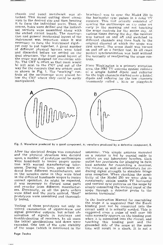
Fig. 5. Waveform produced by a good component, A; waveform produced by a defective component, B.
After the electrical design was completed and the physical structure was decided upon, a number of prototype oscilloscopes were hand -built to insure proper opera- tion with normal manufacturing toler- ances. During this time, parts were or- dered from different manufacturers, and as the samples came in they were tried in the different handmade scopes to insure correct operation. As might be expected, it was necessary to discard some parts and re -order from different manufactur- ers. Eventually, as all the parts orders were filled and the parts arrived, "final" prototypes were assembled and thorough- ly tested.
Testing of these prototypes not only in- volved examination of square -wave and signal generator outputs, but actual ob- servation of signals in receivers and troubleshooting of receivers. In all cases the initial specifications laid down were exceeded. One test of the sync stability of the scope (which is mentioned in the
antenna). This simple antenna mounted on a rotator is fed by coaxial cable to outlets on our laboratory benches. Each outlet has provisions for plugging in twin lead antenna for connecting a receiver, the rotator, as well as attenuators for re- ducing signal strength to simulate fringe area reception. When checking the sensi- tivity of the Model 250 we were able to consistently obtain usable TV horizontal and vertical sync patterns on the scope by simply connecting the vertical input of the scope through a detector probe to the antenna terminals!
In the Instruction Manual for assembling the scope it is suggested that the Z-axis binding post not be connected into the circuit until it is actually needed. This is suggested since a pulse of well over 100 volts normally appears on the binding post when it is connected into the circuit, and touching this binding post and the grounded side of the scope at the same time will result in a shock. It is not a
Page Twelve

fatal shock under normal circumstances hut it sure can give you a jolt-I know, because I touched it several times!
The frequency of this pulse depends on the setting of the horizontal sweep oscilla- tor in the scope and the high magnitude of the pulse is due to the fact that we used two blanking amplifiers instead of the usual one found in most oscilloscopes.
Some time after the Model 250 oscillo- scope was on the market, we found that this pulse at the Z-axis could then be used to check inductances in the horizon- tal sweep of a television receiver! To do this, simply set the sweep oscillator of the scope approximately at the horizontal sweep frequency of 15,750 cps and apply the resultant high amplitude pulse at the Z-axis to the part under test. With a good part this pulse applied to the inductance of either the flyback transformer, yoke, width coil, ringing coil, etc., results in the waveform as shown in Fig. 5A. A defec- tive part such as a short of just one turn to another will show as in Fig. 5B. To make this test it is only necessary to con- nect a short piece of wire between the Z-axis binding post and the vertical input of the scope. Regular test leads are used to connect across the part. For example, to check a flyback transformer, connect
n r i
G.E. Announces Availability Of 1959 Radio -Phono Manuals
In the April -May issue of NRI News, we featured a short article on how students and graduates could obtain service man- uals for 1959 G.E. TV receivers.
Now, the General Electric Company also announces a subscription plan for new Radio/Phono service manuals. Radio tech- nicians can obtain these manuals auto- matically as they are printed by forward- ing their request and $2.50 to:
General Electric Co. Radio Receiver Department Technical Publications 869 Broad Street Utica, New York
Information on any additional G.E. radio service data may be obtained by also writ- ing to the above address.
nri- Scanning-
Every time a man puts a new idea across, he finds ten men who thought of it before he did-but they only thought of it!
the ground binding post of the scope to B- in the TV under test, remove the plate cap of the horizontal output tube, and connect the vertical input binding post of the scope to this plate cap lead of the flyback transformer.
Before this pulse at the Z-axis binding post can be used for such testing a slight change is necessary. Normally the bind- ing post is connected by a length of wire to a .01-mfd capacitor on the front etched circuit board. The other lead of the ca- pacitor connects to the plate of the second blanking amplifier stage. It is necessary to reduce this coupling by using a twisted wire "gimmick." This is simply done by connecting one four -inch piece of wire to the binding post, another to the circuit board, and twisting the free ends of the wires together.
In conclusion, the development of the Model 250 oscilloscope might be termed "happy engineering." That is, the design- ers were able to successfully incorporate into this scope just what they felt was needed and to keep out what was con- sidered just advertising fodder. The proof, though, is "in the pudding" and the many hundreds of satisfied Model 250 owners made this a most satisfying and reward- ing project.
n r i
n r i
What America really needs is more young people who will carry to their jobs the same enthusiasm for getting ahead that they display in traffic.
Page Thirteen

Add the
NRI Professional Model 114
Resistor -Capacitor Tester to your servicing equipment
Q,.t,`
Measures:
Resistance
Capacity
Leakage
Power Factor
10 mmfd. to 1500 mfd.
1 ohm to 150 megohms
Gives:
Greater profits Satisfied customers
More efficiency
Added confidence
Dependability & long -life Professional appearance
Page Fourteen
This service instrument has a definite place in every modern Radio and Tele- vision Service Shop, It speeds up servic- ing and gives you more confidence. In- creases profits and customer good will.
Uses Highly Accurate Bridge -Type Circuit
Bridge type measuring devices are widely accepted by laboratory engineers because of their great accuracy. The NRI Model 114 is guaranteed to be accurate ±5% or better. It is no trouble to select matched resistors or exact capacity condensers for use in critical circuits. Especially valuable in servicing AM, FM, TV receivers, and High Fidelity equipment.
Tests All Types Condensers In Radio-TV
This tester is designed to do a complete job of testing all condensers used in Radio and Television receivers. This it does with ease, checking capacities as low as 10 mmfd. and as high as 1500 mfd. You can determine the capacity of small, color-

. .,L . 1..4 . Y
coded condensers more quickly than you can figure out their values using the color code-and you check the condenser at the same time! Testing electrolytic filter con- densers is just as easy. You measure ca- pacity, leakage, and power factor. (A high power factor tells you in advance that a filter condenser will need replacing soon.) Checking video low -frequency compensat- ing condensers, by-pass condensers, and coupling condensers is just as simple.
Extra Sensitive Leakage Test Circuit
The leakage test circuit provides two ranges of sensitivity, one for paper, mica, and ceramic condensers, and the other for electrolytic condensers. The paper -mica range is ultra -sensitive, detecting leakage resistance well above 100 megohms. Ac- tual d.c. working voltage of condensers, up to 400 volts, is applied, giving an indica- tion far superior to conventional low -volt- age leakage checks made with an ordinary ohmmeter. And the leakage test voltage is continuously variable. An ideal source of d.c. voltage for polarizing electrolytic condensers.
Power Factor Test
As electrolytic condensers age, their power factor usually increases. Electrolytic con- densers with a power factor of more than 15% should normally be replaced. This test tells you which condensers are likely to fail soon. Saves time and headaches. En- ables you to guarantee your work. Your repair jobs stay fixed. The Model 114 in- dicates power factor directly. This is a test which cannot be made with an ohm- meter.
Measures Wide Range Of Resistance
Four overlapping resistance ranges, from 1 ohm to 150 megohms. Bridge type cir- cuit is much more accurate than conven- tional ohmmeter.
Operating Instructions Supplied
Easy to operate. A manual giving step by step instructions is supplied. A profes- sional serviceman needs professional in- struments. Note excellent appearance of controls and dials on front panel. You will be proud to own this instrument.
Specifications
1. Four Capacity ranges: 10 mmfd. to 1500 mfd.
2. Four resistance ranges: 1 ohm to 150 megohms.
3. Power Factor Scale: 0 to 50% direct reading.
4. Bridge -type measuring circuit with tun- ing eye null indicator.
5. Variable leakage test and polarizing voltage, 0 to 400 volts. Dual sensitivity leakage test circuit.
6. Uses type 6X4 rectifier and type 6E5 null indicator.
7. Extra heavy rubber -covered test leads and two special test plugs for use in meas- uring very small capacity or very high resistance.
8. Power requirements: 50-60 cycle, 110- 125 volts A.C. (Cannot be operated on D.C. or 25 cycle A.C.)
9. Size: 9°4" x 7(1h" x 61/4". Actual weight: 511/2 lbs. Shipping weight 8 lbs.
10. Black wrinkle finish cabinet. Deep etched brushed aluminum panel with etched black lettering.
11. 90 -day EIA warranty against defects.
ORDER BLANK
Supply Division
National Radio Institute
3939 Wisconsin Ave.
Washington 16. D. C.
Gentlemen:
I enclose $39.95 (check, money order or
bank draft) for which send me, express
collect, one Model 114 NRI Professional
Resistor -Capacitor Tester.
Tell me how I can buy this instrument
on monthly terms.
Name
Student No.
Address
City Zone State
Express Office
(if you live in Washington, D. C.. add 2% D. C Sales Tax)
a_
Page Fifteen

New 1959 Roll Charts Now Available For NRI Professional Models 70 and
71 Tube Testers The NRI Supply Division now has in stock new, up-to-date roll charts for the Models 70 and 71 Tube Testers. Each roll chart lists over 500 most used and newly intro- duced Radio-TV tube types and is mailed with a special supplement list of infre- quently encountered tube types, obsolete types, tubes manufactured for special or limited applications and foreign tubes. To determine if you already have this new chart: Model 70 Owners: Roll your present chart all the way to the top. If the form num- ber shown in the left hand column is NRI-70 3-59, you have this latest chart. If the form number is not NRI-70 3-59, your present chart is obsolete and should be replaced. Model 71 Owners: Roll your present chart all the way to the top. If the form num- ber shown in the left hand column is NRI-71 (1-59), you already have this latest chart. If the form number is not NRI-71 (1-59), your present chart is obsolete and should be replaced. Price of the new charts is $2.00 each postpaid. To order, use coupon below. Please be sure to indicate Model of your tester in the box provided.
National Radio Institute Supply Division 4 RL 3939 Wisconsin Ave. 5 RL Washington 16, D. C.
I enclose $2.00 (check or money order). Send me postpaid, a 1959 roll chart for my NRI Pro- fessional
D Model 70 Tube Tester Model 71 Tube Tester
Name
Student Number
Address
City Zone State (If you live in Washington, D. C., please add 2% D. C. Sales Tax)
Spare Time You, too, have spare time. The man who says, "I would do such rand such a great thing, if only I had the time," would do nothing at all if he had all the time on the calendar. There is always time-spare time-at the disposal of every human being who has the energy to use it.
Bruce Barton
Westinghouse Builds World's Largest "Hi-Fi" Amplifier
Employees of the Westinghouse Industrial Electronic Department have just put the finishing touches on the world's largest and most powerful "hi-fi" amplifier.
The unit is 24 feet long, seven feet high and three feet wide. It weighs in the neighborhood of ten tons. This amplifier is valued at over $100,000-which is prob- ably more than the average hi-fi enthusi- ast would care to invest!
According to Mr. W. J. Delaney, Jr., man- ager of the Electronics Division, the am- plifier is perfectly capable of providing good music reproduction with an output capacity of 200,000 watts. But this isn't the way it will be used.
In actual operation, the amplifier will be used to simulate the vibrations of mis- siles in flight. It will be possible to test missile components to destruction if neces- sary in order to establish how much vi- bration parts can withstand.
n i- - Removing Picture Tube
Residual Spots
In your Television service experiences you will very likely run across complaints of visible spots remaining on the screen for several seconds after the set has been turned off. Although this "afterglow" usually disappears quickly in about four or five seconds without much chance that that undeflected spot will cause a screen burn, in some sases a combination of con- ditions will permit the light to linger on the screen somewhat longer. If the spot seems to be fairly bright and is visible for five to ten seconds or longer, there is dan- ger that the screen can be damaged. We know, of course, that the spot lingers because when the set is turned off, the high -voltage charge is not entirely and immediately dissipated, and the picture tube cathode remains in a semi -emitting state for at least several seconds after filament voltage is switched off.
To more quickly dissipate the high -voltage charge, the user can increase the picture tube beam current by turning the bright- ness control to maximum immediately be- fore turning the set off. This action will have the effect of decreasing the resistance across the high -voltage and therefore the remaining charge should immediately dis- appear.
(Page twenty-four, please) Page Sixteen
RI ALUMNI NEWS John Babcock President F. Earl Oliver Vice President Jules Cohen Vice President William Fox Vice President Howard Smith Vice President Theodore E. Rose Executive Sect.
Nominations For 1960 Despite the current weather, it won't be long before the birds will be flying south and autumn will be upon us. To members of the NRI Alumni Association autumn also brings with it our election campaign when we choose the National Officers-a President and four Vice-Presidents-to serve the Association in the ensuing year.
First in the order of events is to nominate the candidates. The nominees for Presi- dent will be the two members for whom is cast the greatest number of votes for that office. Similarly, the candidates for Vice -Presidents will be the eight men re- ceiving the largest number of votes for a Vice -Presidency.
Nominations must be completed by August 25, 1959. Be sure to mail your ballot in plenty of time to reach Washington by then. National Headquarters will tally the votes received on or before that date and the names of the candidates nominated will be published in the October -November is- sue of the NR'I News. From among the list of candidates nominated members will cast their ballots for their choice of a Presi- dent and four Vice -Presidents. The re- quired ballots will be furnished in the Oc- tober -November issue.
This election is being held as prescribed in our Constitution, Article VI, quoted below :
1. The election of the President and the Vice -Presidents shall be by ballot.
2. The President shall be eligible for re- election only after expiration of at least one year following his existing term of office, and when not a candidate for Presi- dent, may be a candidate for any other office. Other officers may be candidates to succeed themselves, or for any other, but not more than one, elective office in the Association.
3. The election of officers shall be held in October of each year, on the day desig- nated by the Executive Secretary, but not later than the twenty-fifth of the said Month.
4. The Executive Secretary shall advise Members by letter or through the columns of the NRI News, on or before August first of each year that names of all nominees shall be filed in his office not later than August twenty-fifth following.
5. Each Member shall be entitled to sub- mit, in writing, one nomination for each office, and the two nominees receiving the highest number of votes shall be the nomi- nees for the office for which nominated.
6. The Executive Secretary, before placing any name on the ballot, shall communi- cate with each nominee, to ascertain his acceptance of the office, if elected. If such tentative acceptance is withheld, the eligi- ble nominee having the next highest num- ber of votes shall be the nominee for that office.
7. The Executive Secretary, on or before October first of each year shall furnish Members a ballot listing the names of the nominees for each office.
8. No Member shall be entitled to vote if he is in arrears in the payment of dues.
9. Ballots, properly executed and valid ac- cording to the instructions plainly printed thereon, shall be returned to the Execu- tive Secretary on or before midnight of October twenty-fifth of each year. 10. The Executive Secretary shall desig- nate three Election Tellers from the staff of the Institute, who shall count the bal- lots and certify the results, together with the return of the ballots, to the Executive Secretary.
11. In. the event of a tie vote for any of- fice, the Executive Secretary shall cast the deciding ballot.
12. The nominee receiving the greater num- ber of votes for the office for which nomi- nated shall be declared by the Executive Secretary to be elected to that office, and notice of such election be forwarded in sufficient time, prior to January one, to permit such elected officer to enter upon the duties of said office on that date.
Page Seventeen

As provided in Article VI of our Constitu- tion, John Babcock of Minneapolis will on December 31 terminate his office as Presi- dent and the newly -elected President will then take over on January 1. But as his fellow -members in the Minneapolis -St. Paul Chapter are well aware this will not mean a lessening of John Babcock's ef- forts and interest in the Alumni Associa- tion.
There is hardly any question of the out- standing candidate for the Presidency in this year's election. It is easily Thomas Hull of the New York City Chapter, who ran John Babcock such a close second for the office in last year's election. Tom Hull has worked long and hard for his Chapter and the Association. Recognition was twice before given him by his being elected a Vice -President in 1954 and President for 1955. The further recognition of his elec- tion as President again this year would only be in keeping with his continued ef- forts on behalf of the Association.
Our Constitution prohibits the President succeeding himself in office-he cannot serve two successive terms-but this re- striction does not apply to the Vice -Presi- dents. The current Vice -Presidents may therefore be reelected. They are Howard Smith of Springfield, Mass.; Jules Cohen of Philadelphia; William Fox of New York City; and F. Earl Oliver of Detroit.
Since they have demonstrated the neces- sary ability and leadership, the chairmen of the various local chapters of the Alumni Association should be also considered in the front rank of candidates for National Office, provided they are also members of the Alumni Association. These chairmen are listed in the Directory of Local Chap- ters.
Additional names are given under "Nomi- nation Suggestions." These names have been selected according to geographical location so that members may have the widest possible choice of candidates. Mem- bers may nominate whomever they wish, provided only that the candidates they choose are members of the Alumni Asso- ciation.
As soon as you make your choice of candi- dates, fill in the Nomination Ballot and mail it to the Executive Secretary in time to reach Washington by August 25.
n
Nomination Suggestions Clinton J. Kinard, Birmingham, Ala. Lawrence W. Brock, Huntsville, Ala. Alex. B. Mendoza, Globe, Ariz.
Oscar C. Cota, Phoenix, Ariz. Earl Brown, Humnoke, Ark. Billy Sanchez, Pine Bluff, Ark. Roland Tomlinson, San Francisco, Calif. Isaiah Randolph, San Francisco, Calif. Vernel R. Guillory, Gardena, Calif. Kenneth E. Williams, Gardena, Calif. John D. Lomba, Sacramento, Calif. Thomas C. Peacock, San Diego, Calif. Martin L. Pluris, Aurora, Colo. Charles J. Esposito, Denver, Colo. Anthony P. Carrano, Bridgeport, Conn. Joseph Medeiros, Hartford, Conn. Chris Latetas, Newark, Del. Fred Anderson, Wilmington, Del. Clarence R. Bostwick, Washington, D. C. Charles E. Hughes, Washington, D. C. James J. Templon, Hollywood, Fla. Leonard M. Smith, Jacksonville, Fla. Harold E. Mulkey, Atlanta, Ga. Roy Mehaffey, Columbus, Ga. Skjold Pedersen, Boise, Idaho Alvin L. Brown, Glenns Ferry, Idaho Walter H. Nicely, Chicago, Ill. Charles C. Mead, Evanston, Ill. Frank Baica, Arlington Hgts., Ill. Andrew Johnson, Chicago, Ill. Joseph Kalvin, Chicago, Ill. Stephen Pavlik, Joliet, Ill. Carl Thomas, Anderson, Ind. Paul M. Ledak, Gary, Ind. Hartle Lathrop, Belmond, Iowa Stanley M. Osiol, Des Moines, Iowa Donald W. Mulford, Garfield, Kans. Cecil E. Kidd, Manhattan, Kans. Joseph H. Wright, Corinth, Ky. Clyde T. Hodges, Louisville, Ky. Patrick Boudreaux, New Orleans, La. Kerman S. Worthy, Baton Rouge, La. Howard E. Lawrence, Bangor, Maine Arthur A. Poulin, South China, Maine Edwin M. Kemp, Hagerstown, Md. S. Austin Hess, Waynesboro, Penna. Karel J. Husar, College Park, Md. Isaac S. Gemmell, Baltimore, Md. Frank W. Seavey, Springfield, Mass. Ralph Serode, Jr., New Bedford, Mass. William Estrella, Fall River, Mass. Joseph J. Rufo, Holyoke, Mass. John Berka, Minneapolis, Minn. Paul Donatell, St. Paul, Minn. Aaron Triplett, Flint, Mich. Charles C. Mueller, Dearborn, Mich. John Harvey, Detroit, Mich. Herman W. Harris, Flint, Mich. Milton Price, Florence, Miss. Gerald P. Pogue, Jackson, Miss. Moses W. Martin, Joplin, Mo. Raymond W. Burke, St. Louis, Mo. Leo C. Cox, Butte, Mont. Victor Spinier, Hingham, Mont. David A. Hedges, Bellevue, Nebr. John C. Pacal, Lincoln, Nebr. Phillip T. Hubel, Henderson, Nev. Robert W. Spainhower, Sparks, Nev. Napoleon Beaudoin, Berlin, N. H. Charles T. Gove, Laconia, N. H. Gustav Godusch? Bayonne, N. J.
Page Eighteen

George A. Fox, Linden, N. J. Earl W. Harrel, Carlsbad, N. Mex. Robert E. Riddle, Organ, N. Mex. David Spitzer, Brooklyn, N. Y. James Eaddy, Brooklyn, N. Y. Frank Catalano, New York, N. Y. Cres Gomez, Union City, N. J. Onte Crowe, Brooklyn, N. Y. J. D. Wilson, Buffalo, N. Y. Norman E. McCoy, Charlotte, N. C. Ray A. Young, Greensboro, N. C. Robert G. Pearson, Fargo, N. Dak. Clarence Kabella, Lidgerwood, N. Dak. Luther M. Elliott, Akron, Ohio John J. Misher, Cleveland, Ohio John Shaffer, Clinton, Okla. Elmer Robb, Kiowa, Okla. Zack F. Orr, Dallas, Oreg. Matt Lisius, Redmond, Oreg. Frank P. Skolnik, Pittsburgh, Penna. Carl E. Bryant, Sr., Philadelphia, Pa. Howard A. Balzer, Pittsburgh, Pa. Lewis Yost, Reading, Pa. E. Richard Stitely, Waynesboro, Pa. Michael Hawrilla, Johnstown, Pa. Lionel C. Turegano, Cranston, R. I. Ernest W. Taylor, Pawtucket, R. I. Charles J. Mull, Anderson, S. Car. G. W. Wingard, Columbia, S. Car. William E. Caswell, Aurora, S. Dak. John Wenzel, Gettysburg, S. Dak. James A. Byrn, Charlotte, Tenn. George W. Yokley, Kingsport, Tenn. Alfred R. Gonzales, El Paso, Texas Alonzo B. Gibson, Houston, Texas William A. Mortensen, Delta, Utah Ernest A. Bartell, Ogden, Utah C. R. Warner, Alexandria, Va. V. F. Gilliam, Lynchburg, Va. Everett L. Sartelle, Barre, Vt. Andrew W. Davis, Bethel, Vt. George D. Hamilton, Bremerton, Wash. Gabriel Vatne, Kent, Wash. Raymond Gray, Cameron, W. Va. S. A. Wetzel, Clarksburg, W. Va. Edwin E. Kaphiem, Milwaukee, Wis. Robert Krauss, Milwaukee, Wis. John H. Johnson, Cheyenne, Wyo. Edward Leis, Sheridan, Wyo. Chesley C. Fowler Gander, Nfld., Canada Burton V. Hoyt, Millville, N. B., Canada Oalkland E. Beck, Halifax, N. S., Canada Kenneth Ackroyd, Bath, Ont., Canada John Tremblay, Jonquiere, P. Q., Canada Anthony Hladyboroda, Mikado, Sask., Can. Albert Johnson, Brandon, Man., Canada Thomas W. Dean, Comax, B. C., Canada
n r ti
All NRI Alumni Members Should Vote
Let's do our part to help the staff handling the elections by submitting ballots early. Polls for nomination close August 25, 1959.
Nomination Ballot
T. E. Ross, Executive Secretary NRI Alumni Association, 3939 Wisconsin Ave.,
Washington 16, D. C.
I am submitting this Nomination Ballot for my choice of candidates for the coming election. The men below are those whom I would like to see elected officers for the year 1960.
(Polls close August 25, 1959)
MY CHOICE FOR PRESIDENT IS
City State
MY CHOICE FOR FOUR VICE-PRESIDENTS IS
1.
City State
2.
City State
3.
City State
4.
City State
Your Signature
Address
City State
Student Number
Page Nineteen

NRI ALUMNI NEWS
Chapter Chatter MILWAUKEE CHAPTER reports the ad- mittance pf two new members: Gary J. Locher and Stephen J. Balister. Glad to number you among the membership of the Chapter, gentlemen.
Recent meetings have featured general discussions on TV circuits in which Slavko Petrich, Stanley Ward, Ralph Lassen and Chairman Philip Rinke participated.
Members decided against holding the cus- tomary annual picnic this summer.
The Chapter has inaugurated a series of discussions on the use of the oscilloscope in TV servicing. Ralph Lassen was elected to head up this program and Slavko Petrich has furnished a TV receiver to be used for demonstration purposes during the program.
NEW ORLEANS CHAPTER made a con- ducted tour through Station WWL-TV, during which the station engineer, Mr. Rousseau, delivered a technical lecture to the group.
HAGERSTOWN (CUMBERLAND VAL- LEY) CHAPTER was scheduled to wind up its 1958-1959 season with a picnic to be held at Waynesboro, Pa. But up to the time this issue of the News went to press, no report had been received on this event.
At the final regular meeting Sam Hess and Mel Foreman demonstrated the popular B & K Television Analyzer and reports on trips to WGAL-TV in Lancaster, Pa., and to the Baltimore Chapter, were given by Harry Straub and Ed Kemp, respectively.
Meetings have been suspended for July and August. The first regular meeting of the new season will be held on September 10.
CHICAGO CHAPTER has undertaken a servicing program which will cover the RCA 630 from the front end to the picture tube and of servicing equipment brought in by members every fourth Wednesday of the month. Every member will personally go through the servicing procedure and become familiar with each piece of test equipment.
In starting on the servicing of the RCA 630, Chairman Teresi explained that the first thing to do was to study the sound IF strip, but before getting into it, he
thought it best for the members to check all the voltages in the sound and IF sec- tions, then after becoming familiar with the schematic of these sections and being satisfied that the voltages were normal, the members would be ready to start on the program.
The business meeting was adjourned and the servicing session was begun. Walter Nicely and several members busied them- selves repairing an amplifier. Chairman Teresi with a few of the other members had a Traveler TV receiver that they were trouble -shooting and had repaired by the end of the evening. Secretary Dominski had the other members around the RCA 630 and they completed checking all the voltage measurements in the sound and IF sections. All the members present agreed that this was quite a rewarding servicing session.
At the following meeting, four new mem- bers were admitted to membership: Emil J. Pacyga, J. T. Bunch, James Lee, and Art Munday. The Chapter was pleased to welcome them as members and expect to see them around quite often.
Despite the weather, attendance at the meetings has been increasing and the mem- bers expect to see it continue to do so. Once the Chapter's program gets well under way, the members will receive many benefits. In view of this, the membership voted to continue with regular meetings throughout the summer.
DETROIT CHAPTER'S Stanley Szafran and Secretary Ellsworth Umbreit demon- strated the synthetic stereo amplifier that they built and entertained the members with some good music.
Members have continued to devote most of their time to building the Chapter's TV Panel Board. However, some time was taken out from this project to work on a TV receiver brought in by John Korpalski.
Following its annual June party, the Chap- ter suspended meetings for July and Au- gust. The first meeting of the 1959-1960 season will be held on Friday, September 11.
PHILADELPHIA - CAMDEN CHAPTER held its 25th Anniversary Celebration at the Boulevard Ballroom, Philadelphia, on May 11. And what a party! Including Chapter Members, their wives and mem- bers of their families, and guests, well over a hundred persons were present. You can be sure they made the most of the event. Those members who did not attend not only missed the time of their lives but also a high spot in the history of the Chapter.
Page Twenty

A small group of members and guests at Philadelphia - Camden Chapter's 25th Anniversary Party. L to r: Harvey Morris, Joe Burke, Charlie Fehn, Dave Spitzer, Ted Rose, John Pirrung, J. B. Straughn, Fred Seganti, and Charles Wells.
In rear, Norman Kraft.
The party began with an excellent roast beef dinner-delicious and far more than anybody could eat-after which the Master of Ceremonies, Chairman John Pirrung, called up the speakers for the evening. Ted Rose, Executive Secretary of the NRI Alumni Association, led off with con- gratulations to the members on their envi- able record of success and traced the
Placard acknowledging donors of door prizes and favors at Philadelphia -Camden Chapter's 25th
Anniversary Party.
formation and early history of the Chapter by reading ex- cerpts from the June -July and August -September, 1934, issues of the NRI-TV News. He was followed by J. B. Straughn of the NRI Staff and various Chapter Members - including Charlie Fehn, Harvey Morris, Norman Kraft, and others- and Dave Spitzer, Secretary of the New York City Chapter, who attended the party accom- panied by Mrs. Spitzer.
Chairman John Pirrung then called upon Secretary Jules Cohen to introduce the enter- tainers for the evening: Dick Frolick and his accordian; Marilyn Ostroff, one of the member's daughters who played the piano; Chapter Member Nick Zandlebeck and his har- monica; Roy Pearstein on the Vibraphone; and last but not least, Pete Schissler played the
piano for a community sing. Without ex- ception these entertainers performed re- markably well, as was evident from the enthusiasm of the audience.
Following the entertainment Secretary Jules Cohen supervised a raffle for the dis- tribution of the very extensive supply of door prizes. Let it be said here that the Chapter received generous support in the quantity and quality of favors and door prizes. Practically all the distributors and dealers in Philadelphia contributed some- thing and some of them donated items of considerable value. The Chapter fully ap- preciated their generosity and cooperation.
The evening was topped off with dancing, which lasted until close to midnight. It was a celebration that will be long remem- bered by the members and guests who par- ticipated in it.
Five more new members have been added to the Chapter's already -large member- ship. They are William McCombe, John J. Adams, James Domican, Robert Woodland, and Eugene J. Chwastek. Congratulations to these new members!
The Chapter voted to hold only one meet- ing in July and August-the Service Night meeting on the second Monday of each month. The regular twice -monthly meet- ings will be resumed in September.
LOS ANGELES CHAPTER has lately held several meetings at Robert Belew's place, 521 So. St. Louis St., near a lake in East Los Angeles, at which Bob graciously served coffee and doughnuts to the mem- bers at the termination of the meetings.
Page Twenty-one

Earl Dycus exhibited three films at these meetings. One was on building a Television transmitter on top of Mt. Washington in New Hampshire, another was a travel film on Africa. The other was devoted to Dy- namic Measurement-determining the power of Electronics, of machines used in the refinery of oil.
Earl Dycus also brought in a dog Tele- vision receiver to be worked on by the members, which the members agreed was a dilly.
Vernel Guillory was elected Treasurer to replace Mike Raftis, who resigned the of- fice.
Theodore Mau is the most recent member to be admitted to membership in the Chap- ter. A cordial welcome to you, Ted!
MINNEAPOLIS -ST. PAUL (TWIN CITY) CHAPTER'S John Berka, former chair- man and a full-time Radio-TV serviceman with a wealth of experience, has been con- ducting a series of talks on TV servicing. At one meeting he concentrated on DC re- storers and sync circuits, discussed com- ponent failures and how to trouble shoot in these circuits. At the following meeting he covered the horizontal oscillator circuit, the trouble symptoms, and explained the best ways to diagnose and repair them. Members get a great deal of practical in- formation and help from these talks by John.
Paul Donatel won the NRI Model 240 Volt -Ohmmeter which was raffled off at the June meeting. At the same meeting, Francis Troyer, for the second time in a row, won the door prize of $20 to be used for the purchase of test equipment by the winner, Francis used part of the first door prize he won to purchase a Tube Caddy from NRI.
Because of the large number of members on vacation in July, the July meeting was cancelled. The next regular meeting will be held on August 13th.
SAN FRANCISCO CHAPTER'S Chairman Art Ragsdale, R. Tomlinson and Pete Sal- votti assembled the NRI Model 240 Volt - Ohmmeter donated to the Chapter by National Headquarters. They then checked and adjusted it, and it was found to work properly. The Volt -Ohmmeter will be used for testing purposes at the Chapter's dog sessions.
B. O. Kidd brought in a TV set with which he was having trouble. Andrew Tillotson and Sidney Mahler aided him in locating and correcting the trouble. Another in -
Directory of Local Chapters Local chapters of the NRI Alumni Association cordially welcome visita from all NEI students and graduates as guests or prospective mem- bers. For more information contact the Chair- man of the chapter you would like to visit or consider joining. BALTIMORE CHAPTER meets 8:00 P.M., sec- ond Tuesday of each month, 100 N. Paca St., Baltimore. Chairman: Joseph Dolivka, 717 N. Montford Ave., Baltimore, Md. CHICAGO CHAPTER meets 8:00 P.M., second and fourth Wednesday of each month, 666 Lakeshore Dr., West Entrance. 33rd Floor, Chicago. Chairman: Charles Teresa, 3001 N. Norica, Chicago, Ill. DETROIT CHAPTER meets 8:00 P.M.. second and fourth Friday of each month St. Andrews Hall, 431 E. Congress St., Detroit. Chairman: John Nagy, 1406 Euclid, Lincoln Park, Mich. FLINT (SAGINAW VALLEY) CHAPTER meets 7:30 P.M., second Saturday of each month, 3149 Richfield. Flint. Chairman: Wil- liam Neuman, 1613 S. Kiesel, Bay City, Mich. HAGERSTOWN (CUMBERLAND VALLEY) CHAPTER meets 7:30 P.M.. second Thursday of each month, North Hagerstown Senior High School, Hagerstown, Md. Chairman: Reginald Ankeney, 138 Main St., Clear Spring, Md. LOS ANGELES CHAPTER meets 8:00 P.M., second Friday of each month, St. Joseph's Catholic School Hall. 1220 S. Los Angeles St., Los Angeles. Chairman: Thomas McMullen, 1002 W. 187th Pl., Gardena, Calif. MILWAUKEE CHAPTER meets 8:00 P.M., third Monday of each month. Radio-TV Store & Shop of S. J. Petrich, 5901 W. Vliet St., Milwaukee. Chairman: Philip Rinke, RFD 3, Box 356, Pewaukee, Wis. MINNEAPOLIS -ST. PAUL (TWIN CITY) CHAPTER meets 8:00 P.M., second Thursday of each month, Walt Berbee's Radio-TV Shop, 915 St. Clair St., St. Paul. Chairman: Walter Berbee, 328 E. Co. ltd., A-2. St. Paul, Minn. NEW ORLEANS CHAPTER meets 8:00 P.M., second Tuesday of each month, home of Louis Grossman, 2229 Napoleon Ave., New Orleans. Chairman: Herman Blackford, 5301 Tchoupl- toulas St., New Orleans, La. NEW YORK CITY CHAPTER meets 8:30 P.M., first and third Thursday of each month, St. Marks Community Center, 12 St. Marks Pl., New York City. Chairman: Edward McAdams, 3430 Irwin Ave., New York 63, N. Y. PHILADF.T.PHIA-CAMDEN CHAFFER meets 8:00 P.M. second and fourth Monday of each month, Knights of Columbus Hall, Tulip & Tyson Sts., Philadelphia. Chairman: John Pirrung, 2923 Longshore Ave., Philadelphia, Pa. PITTSBURGH CHAPTER meets 8:00 P.M., first Thursday of each month, 134 Market Pl., Pittsburgh. Chairman: Thomas D. Schnader, R.D. 3. Irwin, Pa. SAN FRANCISCO CHAPTER meets 8:00 P.M.. first Wednesday of each month, 147 Albion St., San Francisco. Chairman: J. Arthur Ragsdale, 1526 27th Ave., San Francisco, Calif. SOUTHEASTERN MASSACHUSETTS CHAP- TER meets 8:00 P.M., last Wednesday of each month, home of Chairman John Alves. 57 Allen Blvd., Swansea, Mass.
SPRINGFIELD (MASS.) CHAPTER meets 7:00 P.M., first Friday of each month, U. S. Army Hdqts. Building, 50 East St., Springfield, and an Saturday following the third Friday of each month at a member's shop. Chairman: Rupert McLellan, 233 Grove St., Chicopee Falls, Mass.
Page Twenty-two
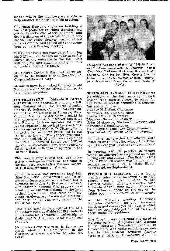
stance where the members were able to help another member solve his problem.
Chairman Ragsdale spoke on building a low cost probe for checking transformers, yokes, flybacks and other inductors, and drew a diagram of the circuit on the black- board. The probe checker was scheduled to be assembled and raffled off to the mem- bers at the following meeting.
Bill Gunter has generously agreed to bring his NRI pennant to each meeting to be dis- played at the entrance to the Hall. This will help visiting students and graduates to locate the meeting place.
Mr. George Taylor is the most recent ad- dition to the membership to the Chapter. Congratulations, George!
Members have been asked to bring in old Radio receivers to be salvaged for parts to build an amplifier.
SOUTHEASTERN MASSACHUSETTS CHAPTER was enthusiastic about a talk and demonstration by Guest Speaker Charles F. Boitano, Communications Offi- cer of Civilian Defense in Swansea, Mass. Chapter Member Lester Cory brought in his home -assembled transceiver and after Mr. Boitano (a ham operator for many years) explained the revised laws on trans- ceivers operating in Class D, Citizens Band, he and other members proceeded to put the set on the air. The proper procedure was emphasized. Mr. Boitano explained that Part 19 (revised September 1958) of the Communications Laws was needed to obtain a station license to operate in the Citizens Band.
This was a very educational and inter- esting evening-so much so that some of the members stayed after the meeting un- til 1:00 a.m. working on the set.
Some discussion was given the local full- time Radio-TV Servicemen's Guild's at- tempt to force part-time repairmen out of business by trying to license all service- men. After a hearing this proposal was ruled out as unconstitutional by the local authorities, who held that Radio and Tele- vision receivers are classified as electrical appliances and so cannot come under the Electrical Code.
This is an excellent example of the help and information available to NRI students and Graduates through membership in their local NRI Alumni Association local chapter.
Mr. Lester Cory, Tiverton, R. I., was re- cently admitted to membership in the Chapter. A warm welcome to you, Mr. Cory!
Springfield Chapter's officers for 1959-1960 sea-
son. Front row: Rupert McLellan, Chairman; Thomas Glog, Vice Chairman. Back row: Howard Smith, Secretary; Orin Hayden, Exec. Comm.; Sam In -
fantino, Exec. Comm.; Norman Charest, Treasurer; John Michnovez, Exec. Comm. and Technical
Adviser.
SPRINGFIELD (MASS.) CHAPTER elects its officers at the final meeting of each season. The officers elected to serve for the 1959-1960 season beginning in Septem- ber are as follows: Rupper McLellan, Chairman Thomas Glog, Vice Chairman Howard Smith, Secretary Norman Charest, Treasurer John Michnovez, Technical Adviser and Executive Committeeman Orin Hayden, Executive Committeeman Sam Infantino, Executive Committeeman
Following the election the officers were installed by the first Secretary, A. L. Bros - seau. Our congratulations to these officers!
In keeping with its practice in former years, the Chapter has suspended meetings during July and August. The first meeting of the 1959-1960 season will be held at its regular meeting place, 50 East Street, Springfield, on September 4.
PITTSBURGH CHAPTER got a lot of practical information on servicing printed boards from a talk delivered by Mr. Edward Gaiden, who is connected with Motorola. At this same meeting Chairman Tom Schnader spoke on the use of the solder pot in the removal of components.
At the following meeting Chairman Schnader conducted an open forum-a question and answer period-during which members invariably get a lot of help with their Radio-TV problems.
The Chapter was particularly pleased to welcome as a guest speaker Mr. William Elder, Electronic Technician for the US Government, who spoke on job opportuni- ties in the Federal Aviation Agency (formerly the C)Vi! Aeronautics Adminis-
Page Twenty-three

tration). Mr. Elder explained the need for technicians in this field and that those who can qualify will be given a fourteen -week special training course at Tulsa, Oklahoma. Anyone interested should get in touch with the Federal Aviation Agency, Washington, D. C., for detailed information.
The Chapter reports that the most recent new members admitted to membership are Joseph A. DeMarchi, Sr., L. E. Wetzel, and Philip J. Alder. A warm welcome to these gentlemen!
BALTIMORE CHAPTER has reported a truly red-letter night. Climaxing two months' correspondence between Balti- more Chapter Chairman Joseph B. Dolivka and Hagerstown Chapter Secretary Edwin M. Kemp, the Baltimore Chapter was privileged to play host to a delegation from the Hagerstown Chapter. The visitors consisted of Chairman Reginald S. Anke- ney, Treasurer Robert J. Saum, and Secre- tary Edwin M. Kemp,
Although this was the first contact be- tween the two chapters so much good fellowship was in evidence that it was de- cided that in the future such visits would be conducted on a regular basis.
The Baltimore Chapter went all out to provide a suitable program for the visitors. Elmer Shue demonstrated two objects of his handiwork of which he and the Balti- more Chapter are particularly proud: the electronic Twenty -One Game and the color organ. The visitors had a lot of fun match-
ing their wits against those of the edu- cated mechanism of the Twenty -One game. Aubrey Hooper contributed to the eve- ning's pleasure with his showing of movies of past Chapter activities.
A swap -talk session produced a gratifying exchange of information beneficial to both chapters. The serving of refreshments was accompanied by the usual telling of jokes, an established custom whenever distin- guished visitors attend a meeting.
The Baltimore Chapter salutes the Hagers- town Chapter for its fine spirit of coopera- tion and wishes it continued success in the years to come.
NEW YORK CITY CHAPTER has put to- gether, with the help of Tom Hull who supervised the operation, the new NRI Model 240 Volt -Ohmmeter. The instru- ment was tested and tried on the Chap- ter's RCA demonstrator board to the satis- faction of all the members, who agreed that the tester does its job very well. The diagram was put up on the blackboard and the operation of each part and its location in the instrument were discussed.
Jim Eaddy, Willie Fox and Cres Gomez continue to give the members information and advice on sets which they recently re- paired.
Having suspended meetings for July and August, the next meeting will be held Sep- tember 17. The Chapter wishes its mem- bers a pleasant and healthy summer.
IT IS CARVED ON 3ADE- EVERY HORSE THINKS , HIS LOAD IS . / HEAVIEST-
c.
Re. U. S. Paf. Ort.: 1958 M -
Newa Syndieafr -
Removing Pic Tube Spots (From page sixteen)
However, because this procedure may not always be convenient to the user or the picture tube itself may already be operat- ing at its maximum brightness, you may find your customer willing to pay for a minor set modification that will eliminate any trace of the "afterglo.
In Fig. 1, page 28, there is shown one cir- cuit, you can use, to eliminate the spot when the brightness control is connected in the cathode circuit of the picture tube. The change is to install an on -off switch in series with the brightness control.
The switch must be made to operate (open) at the same time that the regular set switch opens. Opening the cathode B+ lead, causes the picture tube to conduct heavily and instantaneously dissipate any remaining charge in the high voltage filter condenser.
(Page twenty-eight, please)
Page Twenty-four
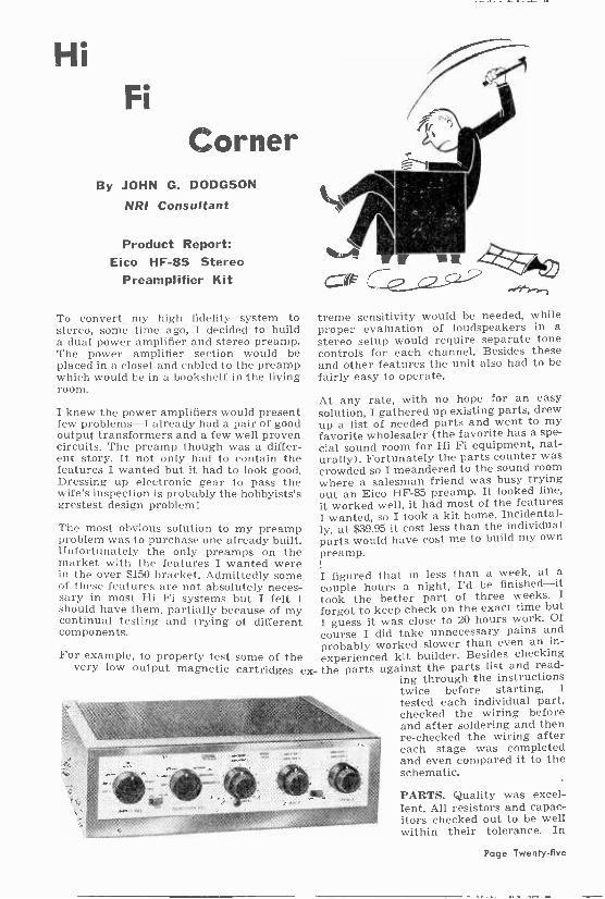
Hi Fi
Corner By JOHN G. DODGSON
NRI Consultant
Product Report: Eico HF -85 Stereo
Preamplifier Kit
To convert my high fidelity system to stereo, some time ago, I decided to build a dual power amplifier and stereo preamp. The power amplifier section would be placed in a closet and cabled to the preamp which would be in a bookshelf in the living room.
I knew the power amplifiers would present few problems-I already had a pair of good output transformers and a few well proven circuits. The preamp though was a differ- ent story. It not only had to contain the features I wanted but it had to look good. Dressing up electronic gear to pass the wife's inspection is probably the hobbyists's grestest design problem!
The most obvious solution to my preamp problem was to purchase one already built. Unfortunately the only preamps on the market with the features I wanted were in the over $150 bracket. Admittedly some of these features are not absolutely neces- sary in most Hi Fi systems but I felt I should have them, partially because of my continual testing and trying of different components.
For example, to properly test some of the very low output magnetic cartridges ex-
_ r G« treme sensitivity would be needed, while proper evaluation of loudspeakers in a stereo setup would require separate tone controls for each channel. Besides these and other features the unit also had to be fairly easy to operate.
At any rate, with no hope for an easy solution, I gathered up existing parts, drew up a list of needed parts and went to my favorite wholesaler (the favorite has a spe- cial sound room for Hi Fi equipment, nat- urally). Fortunately the parts counter was crowded so I meandered to the sound room where a salesman friend was busy trying out an Eico HF -85 preamp. It looked fine, it worked well, it had most of the features I wanted, so I took a kit home. Incidental- ly, at $39.95 it cost less than the individual parts would have cost me to build my own preamp.
I figured that in less than a week, at a
couple hours a night, I'd be finished-it took the better part of three weeks. I forgot to keep check on the exact time but I guess it was close to 20 hours work. Of
course I did take unnecessary pains and probably worked slower than even an in-
experienced kit builder. Besides checking the parts against the parts list and read-
ing through the instructions twice before starting, I tested each individual part, checked the wiring before and after soldering and then re -checked the wiring after each stage was completed and even compared it to the schematic.
PARTS. Quality was excel- lent. All resistors and capac- itors checked out to be well within their tolerance. In
Page Twenty-five

fact, the 5% resistors (an unusual num- ber are used) actually measured within t 1%. Most of the parts are made by the big name American companies but some imported resistors and capacitors were also used. These were top quality parts though, not shoddy imports, and as pointed out they checked well within their ratings.
There were no missing parts nor substi- tutes. In fact, extra hardware was in- cluded-a welcome feature since a couple of screws or nuts always get misplaced.
All of the screws are mounted with lock - washers as are the potentiometers and switches.
INSTRUCTIONS. The manual consists of two parts-an operating section and a separate removable center section that contains the assembly instructions.
As previously pointed out the construc- tion took me a long time, not only be- cause I took needless pains, but the HF - 85 is not a simple unit. It is, after all, two complete preamps on one chassis contain- ing 10 amplifier stages, a power supply, two bass and two treble control networks, two complicated switches, tape head com- pensation, 17 input and output jacks, etc. It is obvious that this kit should not be a layman's first electronic project (no pre - amp or FM tuner should be). However, the instructions are such that only a mini- mum of wiring and soldering experience would be required.
An errata sheet pointed out a few errors in the text. Other than this there were no errors in the text. The instructions were straightforward and for the most part easy to follow. The 7 -position input selector switch is a large complicated 4 -deck affair with terminals on both sides of each deck. This was the most difficult section to wire and a few extra or larger illustrations would have helped. The other sections of the unit were fairly easy to wire.
APPEARANCE AND LAYOUT: Just a quick glance at the wiring of the HF -85 shows that much thought and preliminary work had gone into its sound design. The layout is electrically logical and yet looks good. Terminal strips are used where needed so parts won't be hung without support. The possibility of hum is avoided like a plague. Any signal leads that might
The Wonders of Science Until recently we could only hear static. Now, with television, we can also see it.
NYC Chapter
pick up hum are shielded. In fact there are one, two, three, four, and even five conductor shielded cables used to prevent hum pickup. Ground loops are scrupu- lously avoided. All of the input and output jacks are insulated from the chassis so that the ground side of the jacks can be connected by wire to a central ground point. Naturally all ground connections in each stage are brought to a single point.
The appearance of the unit is excellent. Its size is just about right-not too large and yet not so small that the parts are crowded. The brushed brass and brown steel cabinet comes with the kit. After some unhappy experience with similar metal cabinets I was pleasantly surprised when this one fit perfectly together.
PERFORMANCE. After completing the wiring I bravely cabled it to power am- plifier and speaker, plugged in the turn- table and turned it on without so much as an ohm -meter check. Happily it worked the first time-and it worked perfectly. Even before adjusting the hum control the hum level was satisfactory. After ad- justment hum was inaudible to well below normal listening levels.
Before continuing with any electrical tests I try to always evaluate equipment with a "living with and listening" test for one or two weeks. Otherwise electrical tests might color the listening evaluation. For exam- ple, if a frequency test showed a loss of high frequency response (it didn't) one would tend to listen for this loss at all times.
Due to a heavy schedule it was over two months before I checked out the HF -85. In that time the unit was used for well over 100 hours, both for regular listening and for testing of cartridges, amplifiers, and speakers. The versatility of the unit was worth its weight in gold for these tests. Each channel has its own separate gain and tone controls which can be op- erated separately or together with a built- in clutch mechanism. This permits set- ting them to the different positions re- quired when dissimilar speakers and pow- er amplifiers are used.
I found the tone control action to be superb. These feedback type controls per- mit boosting (or cut) of the very lowest or highest frequencies without affecting the mid -range.
The gain of the preamp is more than ade- quate for normal cartridges. In fact there's so much gain that the user will find it necessary to turn down the gain on the power amplifier or install a gain control if it doesn't have one.
Page Twenty-six
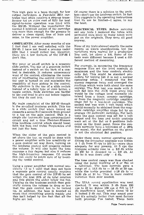
This high gain is a boon though for low output cartridges. A Fairchild 225A car- tridge that often requires a step-up trans- former (at an extra cost of $15) for best signal-to-noise operation was tried with the HF -85. Without the transformer the normal 5 millivolt output of the cartridge was more than enough for the preamp to deliver a clean signal, free of hum and noise, to the power amplifier.
COMPLAINTS. After many months of use I find that I am well satisfied with the HF -85. I have not found a preamp under $150 that I would rather use. However, there are a few features of the HF -85 I don't like.
The pwer or on -off switch is a separate slide switch. The use of a separate switch instead of a switch on the back of a con- trol is desirable. It reduces unnecessary wear of the control, eliminates the neces- sity of readjusting the control every time the unit is turned on and minimizes the possibility of hum pickup in the control. My objection is the use of a slide switch instead of a rotary type or even better, a toggle switch. Slide switches are harder to use and tend to give out before toggles but they do cost less.
My main complaint of the HF -85 though is the so-called loudness switch. This too is a slide switch that when turned on connects a series R -C network from ground to a tap on the gain control. This is a simple abc (automatic bass compensation) circuit and not a true Fletcher-Munsen type loudness control which should boost both the bass and treble frequencies and not just the bass.
When the slider of the gain control is set above the tap, as would be done with a power amplifier with low sensitivity or a gain control set way down, turning on the loudness control will properly reduce the volume. It will also boost the bass response a fair degree but alas it reduces the high -frequency response. Of course this can easily be taken care of by boost- ing the treble control.
Using a power amplifier with normal sen- sitivity (.5 to 1 volt) that does not have a separate gain control usually requires that the gain control of the HF -85 be set within the first 20% of its total rotation and this places the slider below the tap. Turning on the loudness switch then gen- erally causes the volume to drop so low that the gain control has to be turned up. In addition, the bass is boosted so much that everything sounds muddy and this isn't helped by the fact that all the highs are lost.
Of course there is a solution to the prob- lem-don't use the loudness switch. In fact Eico suggests in the operating instructions that its use be limited-I agree, to say the least.
ELECTRICAL TESTS. Before carrying out any tests I replaced the tubes with pretested ones since so many hours were put on the originals. They were all good anyway.
None of my tests showed exactly the same results as Eico's specifications, but the variations were normal for a production line unit, let alone a kit. Some of the tests were different because I used a dif- ferent method of measuring.
For example, in measuring the frequency response Eico set the level controls at maximum and the tone controls electri- cally flat. This might be standard pro- cedure for testing but it is not a normal operating setup. I measured the fre- quency response twice and averaged the readings which were both about the same anyway. The first test was made with .5 volt fed into the AUX input since this would be the voltage level normally ob- tained from a tuner, ceramic cartridge, or from the magnetic cartridge amplifier stage fed by a low-level cartridge. The second test was with 1 volt input which would normally be obtained from the mag- netic cartridge amplifier stage fed by an average (10 millivolt) cartridge. For both tests the gain control was set for 1 volt output and the bass and treble controls were set at the fiat or 0 positions indi- cated on the front panel. Since the con- trols normally have a tolerance of + 20% (or more), the flat position on the panel is not the electrical flat position.
Under these more normal operating con- ditions the frequency response was within ± 1 db from 10 cps to 100 kc-more than adequate for any preamp. At 5 cps the response actually rose to + 2.9 db while at 150 kc it dropped to - 2.9 db. At 200 kc it was down only - 6 db.
The tone control range was then checked using the panel marking of 0 or flat as a reference. The bass controls gave a range of + 14.6 db to - 16 db at 50 cps, while the treble provided +18 db to - 14.96 db at 10 kc. This is more control variation than ever needed.
The RIAA record equalization was next checked. It was within .5 db from 150 cps to 12 kc. Below 150 cps it fell to 1.7 db insufficient boost, while above 12 kc it lacked 2 db cut. This may sound poor but it's actually better than most factory built preamps I've tested. These tests
Page Twenty-seven

were carried out with 10 my input and 1 v output at 1 kc.
Total hum and noise was measured with the gain controls set for 1 volt output with 10 my input at the magnetic jack, and .5 volt at the AUX jack. It was com- pletely inaudible at -53 db at the mag- netic phono input and over -60 db at the high level inputs.
The differences between the channels were insignificant. The frequency response of one channel was within .6 db of the other, while the tone control differences were only 1.8 db. The R1AA equalization varied less than 1 db. Since each channel is provided with its own gain and tone controls even a much greater difference would still be satisfactory.
Neither the NARTB tape head equaliza- tion nor the total preamp distortion was measured.
CONCLUSIONS. So far as electrical tests
n r i
Removing Pic Tube Spots (From page twenty-four)
When the brightness control is in the pic- ture tube control grid circuit, you should connect this switch between the control and ground, as shown in Fig. 2. Switching off the set will cause the grid voltage to become highly positive. The resulting heavy conduction that occurs due to low internal picture tube resistance will very rapidly drain away the high voltage charge.
The extra on -off switch should be put on the control that works the regular set switch. This switch should be removed and a double -pole, double -throw switch substituted.
Where the switch cannot be removed and
ganged with on -off switc
brightness 13+<-4/V\/, control
Figure 1. Placement of spot -elimination switch in cathode circuit of kine.
and listening tests are concerned the Eico HF -85 checked out as good or better than any commercial preamp I've seen. The only real complaint is with loudness control.
The operating instruction manual is ex- cellent and covers just about every appli- cation or problem that might be encoun- tered with HF -85.
Maufacturer's Comment: "Loudness con- trols are (used) to boost difference of loudness levels and should not follow the Fletcher -Munson curve-but the difference of two curves. These curves show a con- siderable difference at bass frequencies, but practically no appreciable difference at high frequencies up to very high levels. Therefore, the loudness compensation should not introduce any treble boost as is often erroneously supposed. Further- more, all Eico power amplifiers have input level controls." In general: "We are very pleased with the report."
basic original circuit
n r 2
ganged with on -off
control `1 switch
bri. htness
Figure 2. Placement of switch in grid circuit.
replaced then it will be necessary to use a new control with a double -pole, double - throw switch. Since many receivers are found with noisy volume or contrast con- trols, at the time they are being serviced, replacing the control to install the new type switch will result in further set im- provement.
n r i
HOW YOU CAN HELP NRI GIVE FASTER SERVICE
When you write to NRI-whenever you send a payment, lesson, or order, please be sure to give your full name, complete address and your NRI Student Number.
If you are a Graduate, write "G" after your Student Number. For prompt han- dling and most efficient service, keep this well in mind. You'll be doing yourself -- and NRI-a real favor if you do.
Page Twenty-eight

Servicing with the Model 114 R -C Tester
(From page seven)
Then set the SELECTOR switch to the 0.1- 50 mfd position. Adjust the MAIN DIAL over its range and try to obtain a null in- dication. If no null is obtained, switch to the 18-1500 mfd "Extended" range and again vary the MAIN DIAL over its range.
When you have obtained a null indication, adjust the POWER FACTOR control so that maximum opening of the NULL IN- DICATOR eye is obtained. You can then determine the capacity by applying the proper multiplying factor to the MAIN DIAL reading and you can determine the power factor of the capacitor directly from the POWER FACTOR control dial.
If it is impossible to obtain a null indica- tion with the SELECTOR SWITCH set to either of these positions, either the capac- ity has dropped to a very low value, or the power factor is extremely high.
To check this latter possibility, set the POWER FACTOR control to "20" on the dial and again vary the MAIN DIAL over its range. If you can then obtain a null indication, adjust the POWER FACTOR control so that maximum opening of the eye is obtained. However, the power factor of the capacitor under test is probably so high that it should be discarded.
The normal power factor for an electrolytic capacitor in good condition is below 10%. In general, capacitors should be replaced when the power factor rises above 15%. In some cases you will find that a capacitor with higher power factor will do the job satisfactorily. However, if the power factor is greater than 15%, it is well to replace the capacitor to reduce the chance of fu- ture trouble.
How To Check Electrolytic Capacitors For Leakage. Set the SELECTOR to the ELEC. position on the Leakage part of the scale. Be sure that you have the negative lead of the test instrument connected to the negative lead of the capacitor and the positive lead of the test instrument con- nected to the positive lead of the capacitor. This is very important. Then turn the LEAKAGE TEST VOLTAGE control clock- wise to the specified working voltage for the capacitor under test. The eye will prob- ably close. It should, however, open in a
minute or two if the capacitor is in good condition and if it has not been idle for so long that the oxide coating in the capacitor has deteriorated. If the capacitor has not been used for a long time, leave it con- nected for two or three minutes and see whether the eye opens. If it does, the ca- pacitor is good; if it does not, the capacitor has excessive leakage and must be re- placed.
If the capacitor under test is shorted, the eye will close as the pointer of the LEAK- AGE TEST VOLTAGE control passes the zero mark. In this case, it is not necessary to make any further tests. Be sure that you observe the polarity markings when test- ing electrolytic capacitors as applying volt- age of the wrong polarity will prevent your obtaining proper results and possibly dam- age the capacitor you are testing.
After you have checked the capacitor for leakage, it is often desirable to again check the capacity and power factor if excessive leakage does not exist because the applica- tion of voltage to an electrolytic will some- times restore the oxide coating and bring the capacity up to normal.
How To Check Ceramic, Mica, and Paper Capacitors. The basic method of measur- ing capacity is the same as in the case of electrolytics, except that the POWER FACTOR control is not used. Set the SELECTOR to the proper position, and vary the MAIN DIAL over its range until a null indication is obtained. Then read the scale to determine the capacity.
When measuring capacity it is usually not necessary to remove the capacitors from the equipment. Simply disconnect one end of the capacitor and then connect the test leads to the two ends of the capacitor to be tested. When measuring the value of mica, ceramic, and extremely small paper capacitors, however, it is best to remove the capacitors from the equipment and use the banana plug binding posts to connect the capacitor to the test instrument.
If the capacitor is extremely small-less than .0005 mfd-it is possible to mentally convert the dial readings to micromicro- farads (mmf) for convenience. The .00001- 005 mfd range of the instrument covers a range between 10 mmf and 5000 mmf. By multiplying the outer scale readings by the factor 10, you can readily convert your readings to micromicrofarads.
No lions are ever caught in mouse traps. To catch a lion, you must think in terms of lions- not in terms of mice. Your mind is always creating traps of one kind or another and what you
catch depends on the thinking you do. -Thomas Dreiver
Page Twenty-nine

o O o 4
q o 0 o ----O
R10 )RII P12
O O O O
t
T
O o
o
O o o
416 C81 1 C71RIM is - 6%4
O
145V
Figure 7. Complete diagram for the Model 114.
Cl -- .05 mfd, 200 volt C2 -- 8 mfd, 500 volt, electrolytic C3 -- Dual -section 4-4 mfd, 500V
electrolytic C4 .01-mfd, 200 volt C5 2-mfd "standards' condenser
(two 1-mfd units in parallel)* C6 .02-mfd "standard" condenser* C7 200-mmf ''standard" condenser set
calibrate the instrument on the .00001-005 mfd range*
R1 25K -ohm, 2 -watt R2 250K -ohm potentiometer (LEAKAGE
TEST VOLTAGE) R3 -- 1.5K -ohm, z -watt R4 -- 10.megohm, 4 -watt R5 -- 500K -ohm, z -watt R6 -- 4K -ohm, z -watt
PARTS LIST
R7 -- , R8 --
R9 -- R10 -
R11 -
s- R12 -
R13
to ~ ' R14
R15 -
P ` R16 -
R17 -
SW1 -
SW2 -
T -
When the SELECTOR Is set to the .00001- .005 mfd position, you will notice that a null indication is obtained when the MAIN
2R
3R
417 25V
3
R
R
100 -ohm, 1 -watt 10K -ohm potentiometer (MAIN DIAL) 90K -ohm
- 20 -ohm "standard" resistor * - 2K -ohm "standard" resistor * - 200K -ohm, "standard's resistor * - 100 -ohm flexible resistor (this part is used only when it is necessary in cálibrating the in- strument at the factory)*
- 100 -ohm, 5 -watt - 270K -ohm, 2 -watt - 1000 -ohm potentiometer (POWER
FACTOR) - 1.2-megohm, i -watt - SPST switch (an R2) - 5 -deck, 11 -position switch
(SELECTOR) - Special power transformer
DIAL nears "1" on the scale. This is an in- dication of the internal capacity of the in- strument, and is normal. When measuring
Page Thirty

the value of capacitors that are below 500 mmf, you should-to obtain best accuracy -subtract the internal capacity of the in- strument, which is a very simple thing to do. Above 500 mmf, this error is negligible.
How To Check Ceramic, Mica, And Paper Capacitors For Leakage. As mentioned pre- viously, the leakage test circuit used in the Model 114 is extremely sensitive. Even the slightest amount of leakage in a capacitor will cause the eye to close partly. For this reason, some care must be exercised in making leakage tests of non -electrolytic
capacitors.
Even the slightest leakage in a coupling capacitor will generally upset the circuit operation. The same amount of leakage in a bypass capacitor, however, might not ad- versely affect the circuit operation. For that reason, we recommend that you use the PAPER -MICA setting of the SELEC- TOR when checking all ceramic, all mica, and all coupling capacitors but use the ELEC. setting of the SELECTOR when testing paper capacitors used in by-pass applications.
HELP! NRI NEWS is your magazine. The con- tents are designed to help you in your work or hobby, to inform you of new de- velopments, or just to give you something interesting in your field to read.
In choosing the contents of each issue of the News we have no trouble in finding material in this immense and growing field of Electronics. Indeed, our problem is more of deciding what is most important -what do our students and graduates want.
This is where you come in. We need your help-tell us what you want in your maga- zine. To make it easy we've drawn up a list of suggested subjects and we've left room so you can add your own sugges- tions. Simply fill it in, remove the page, and mail it to us addressed to The Editor, NRI News, National Radio Institute, 3939 Wisconsin Ave. N.W., Washington, D. C.
By the way, most of the suggested sub- jects have been written up in the past and probably will be in the future, so don't check everything! It would be best to limit yourself to 4 or 5 checks.
I would like to see articles in our NRI News on the following subjects:
(Limit your requests to 5 choices)
SERVICE AND REPAIR: AC -DC Radios Portable Radios (tube type) Transistor Radios Auto Radios Black & White TV-General What in particular? Test instruments-General: What particular instrument'? Hi Fi Amplifiers Hi Fi Preamplifiers Record Changers Tape Recorders Other:
THEORY OR DESCRIPTION OF OPERATION:
AC -DC Radios Transistor Radios Auto Radios Black and White TV Color TV Test Instruments-specify
Hi Fi Equipment-specify
Ohms Law Detectors for FM and AM Capacitors Math for the serviceman Transistors Other:
CONSTRUCTION (DO IT YOURSELF) TEST INSTRUMENTS:
Specify:
RADIO: Add short-wave Add intercom Improve tone Other:
HI FI: Pre -Amplifiers Amplifiers Speaker enclosures Other:
GADGETS-FOR SERVICING, OR HOBBY:
HOME,
Please indicate whether you are a student
or graduate
D
o o
El
o
Page Thirty-one