Embed Size (px)
Citation preview

I N S T I TU TE F O R D EF E N S E A N AL YS E S
The Best of All Possible Worlds:
Applying the Model Driven Architecture Approach to a
JC3IEDM OWL Ontology Modeled in UML
Francisco L. Loaiza-Lemos, Project Leader
Steven P. Wartik John P. Thompson
Dale Visser Edward Kenschaft
25 April 2014
IDA Non-Standard NS D-5113
Log: H 14-000041 Copy
Approved for public release;
distribution is unlimited.
INSTITUTE FOR DEFENSE ANALYSES 4850 Mark Center Drive
Alexandria, Virginia 22311-1882
IDA

About This Publication
This work was conducted by the Institute for Defense Analyses (IDA) under contract DASW01-04-C-0003, Task BL-5-3518, “Army Business Information Systems (BIS) Integration Strategy,” for Army CIO G-6/SAIS-AOD. The views, opinions, and findings should not be construed as representing the official position of either the Department of Defense or the sponsoring organization.
Copyright Notice
© 2014 Institute for Defense Analyses 4850 Mark Center Drive, Alexandria, Virginia 22311-1882 • (703) 845-2000. This material may be reproduced by or for the U.S. Government pursuant to the copyright license under the clause at DFARS 252.227-7013 (a)(16) [Sep 2011].

1
19th ICCRTS
The Best of All Possible Worlds:
Applying the Model Driven Architecture
Approach to a JC3IEDM OWL Ontology
Modeled in UML Topic 3
Authors: Francisco Loaiza, Steve Wartik, John Thompson, Dale Visser, Edward Kenschaft
POC: Francisco Loaiza, Institute for Defense Analyses, 4850 Mark Center Drive, Alexandria, VA 22311; TelNr.: (703-845-6876); email: [email protected].
ABSTRACT This paper describes how, through the utilization of the Ontology Definition Metamodel (ODM), a UML profile for expressing OWL constructs in that language, one can combine the power of semantic modeling done in OWL with the substantive advantages associated with the Model Driven Architecture (MDA) software design approach, namely, the reduction in cost and time required to update and maintain complex information models, and the improved quality of their physical implementations.
Taking the Multilateral Interoperability Programme’s Joint Consultation, Command and Control Information Exchange Data Model (JC3IEDM) as an example of an existing C2 specification written in an Entity Relationship (ER) modeling language, the authors present a detailed workflow that encompasses (a) a methodology for translating existing ER specifications into OWL equivalents, (b) the subsequent conversion of the resulting JC3IEDM OWL ontology into a UML model that uses the ODM profile, (c) the use of the resulting UML model as a Platform Independent Model (PIM), (d) the generation of Platform Specific Models (PSMs) via the application of Query/View/Transformation (QVT) scripts to the JC3IEDM OWL PIM, and (e) the final generation of executable code out of the respective PSMs.
The authors also highlight some of the additional benefits of migrating to OWL as the modeling language for information models, namely, the potential for leveraging the inferencing capabilities of ontology languages, as well as for formalizing rule models associated with information models.


2
1. INTRODUCTION
Using the Web Ontology Language (OWL)[1] to model information can have great benefits. It is semantically richer than many commonly used models, such as entity-relationship (ER) diagrams for relational database systems or class diagrams for information models. The W3C [2], which is responsible for OWL, does not endorse a standard graphical representation, but the Object Management Group’s Ontology Definition Metamodel (ODM)[3] defines how to use the Unified Modeling Language[4] (UML)’s well-known class diagram notation to depict OWL ontologies.
As OWL grows in popularity, it is reasonable to expect that many organizations will want to use OWL for their information models. This raises the question of the most efficient way an organization can produce its OWL-based model, especially if (as is common) it already has a significant investment in another model. A second and equally important question is what an organization does with its OWL model: An organization with a significant investment in using a relational database system for data persistence may be loath to abandon that model. In other words, it may want to use the ontology as a specification but continue using RDBMS technology as the implementation until it has the resources to update all its systems.
This paper describes our experience converting a legacy ER-based information model to OWL, and using that OWL model as the basis for generating DBMS and other implementations. The methodology is broadly applicable. It relies on well-known standards and technologies, in particular OWL, UML, and the Model Driven Architecture.[5]
2. GENERATING OWL ONTOLOGIES FROM LEGACY SPECIFICATIONS
Trying to produce an OWL model from scratch for a complex domain can be a daunting and time-consuming effort. Fortunately, in many cases, extensive modeling work for a domain may already have been done as part of the development of a web-based solution application.
Figure 1. MIP Information Resource Dictionary Model for ER Metadata Specifications
3
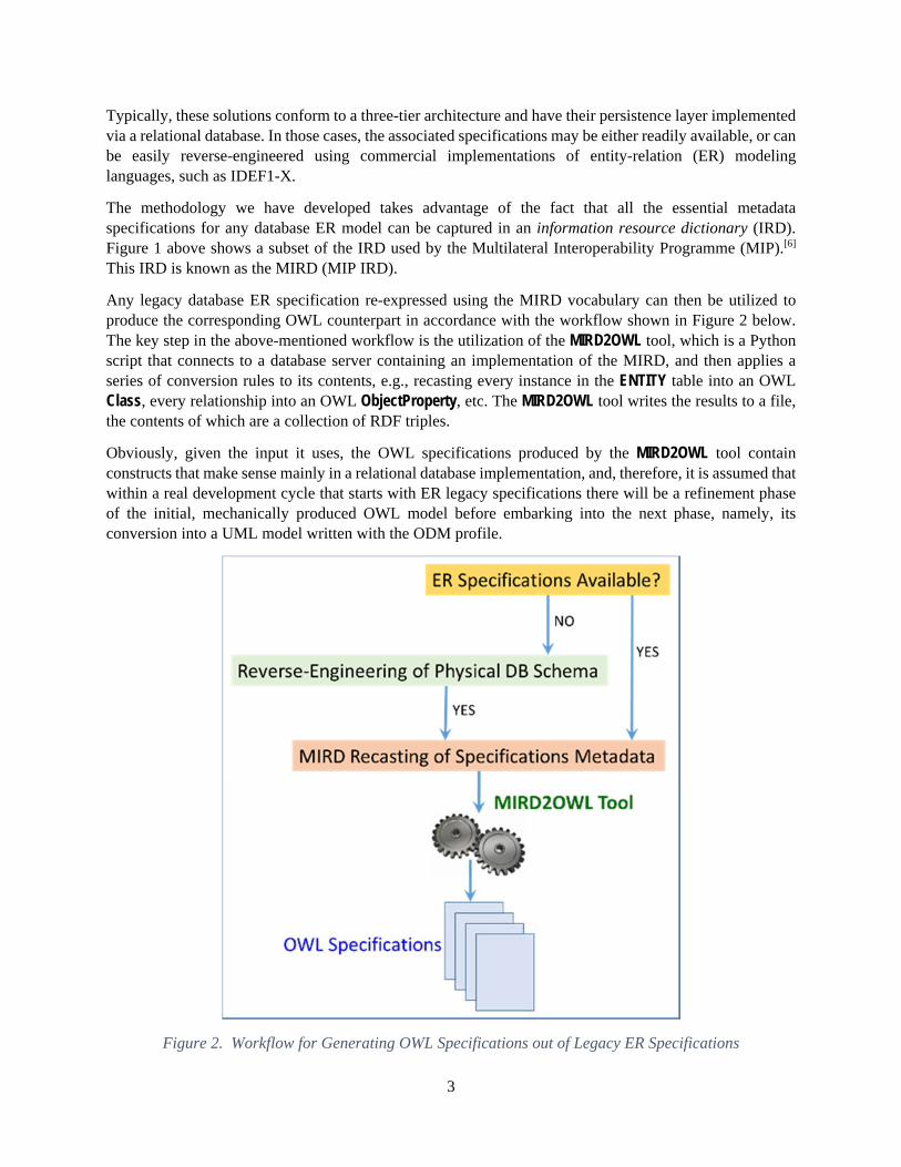
Typically, these solutions conform to a three-tier architecture and have their persistence layer implemented via a relational database. In those cases, the associated specifications may be either readily available, or can be easily reverse-engineered using commercial implementations of entity-relation (ER) modeling languages, such as IDEF1-X.
The methodology we have developed takes advantage of the fact that all the essential metadata specifications for any database ER model can be captured in an information resource dictionary (IRD). Figure 1 above shows a subset of the IRD used by the Multilateral Interoperability Programme (MIP).[6] This IRD is known as the MIRD (MIP IRD).
Any legacy database ER specification re-expressed using the MIRD vocabulary can then be utilized to produce the corresponding OWL counterpart in accordance with the workflow shown in Figure 2 below. The key step in the above-mentioned workflow is the utilization of the MIRD2OWL tool, which is a Python script that connects to a database server containing an implementation of the MIRD, and then applies a series of conversion rules to its contents, e.g., recasting every instance in the ENTITY table into an OWL Class, every relationship into an OWL ObjectProperty, etc. The MIRD2OWL tool writes the results to a file, the contents of which are a collection of RDF triples.
Obviously, given the input it uses, the OWL specifications produced by the MIRD2OWL tool contain constructs that make sense mainly in a relational database implementation, and, therefore, it is assumed that within a real development cycle that starts with ER legacy specifications there will be a refinement phase of the initial, mechanically produced OWL model before embarking into the next phase, namely, its conversion into a UML model written with the ODM profile.
Figure 2. Workflow for Generating OWL Specifications out of Legacy ER Specifications

4
3. GENERATING A UML MODEL FROM AN OWL SPECIFICATION
The OWL file produced via the MIRD2OWL tool can serve as a formal specification of an information model, but it lacks readability. The available OWL editors present visual models of OWL to varying degrees but have limited support for graphical editing. The Object Management Group has proposed the Ontology Definition Metamodel (ODM) profile to address this deficiency. ODM specifies a UML profile for OWL, namely, a collection of stereotypes that direct how to use UML elements to express OWL syntax and semantics. The result is a graphical presentation of an ontology using OMG’s familiar class modeling notation.
The application of the Model Driven Architecture (MDA) software design approach requires the existence of a UML model that can serve as the Platform Independent Model (PIM) out of which, via a mechanism such as the application of Query/View/Transformation (QVT)[7] scripts, the user can generate any desired Platform Specific Model (PSM).
With the release of the ODM UML profile by the OMG it has become possible to develop OWL models within any standard commercial UML modeling tool that supports that profile.
For our demonstration we developed an implementation of the ODM profile that can be used with the Sparx Systems Enterprise Architect (SPARX EA) UML modeling tool.[8] The profile is not fully conformant with the ODM standard. When we started, the available version of ODM was 1.0, which supported OWL 1 but not OWL 2. The Institute for Defense Analyses (IDA) was in communication with the ODM Revision Task Force and adopted its general directions towards OWL 2. As of this writing, the current version of ODM is 1.1 beta. SPARX EA’s capabilities cannot fully support 1.1 beta, and thus, to that extent, we have deviated from the ODM standard.
Leveraging SPARX EA’s Java application programming interface (API), the team built a tool called OWL2EA that can ingest an OWL file and generate the corresponding UML model with the required stereotypes for each of the OWL constructs. Figure 3 below shows the overall concept. Starting with an existing ER specification, such as the one for the Joint Consultation, Command and Control Information Exchange Data Model (JC3IEDM) [9] that has been loaded into a MIRD database, the corresponding OWL specification is produced through the MIRD2OWL tool, and then converted into a PIM written in accordance with the ODM profile using the OWL2EA tool. The JC3IEDM OWL PIM can then be transformed into desired JC3IEDM PSMs, such as a relational database representation of the OWL specifications or an XSD model for defining the structure of XML-based C2 exchanges among JC3IEDM-conformant systems. The details of those transformations are discussed in the following sections.

5
Figure 3. Complete Implementation of the MDA Approach for Using an OWL Model as the PIM
4. THE JC3IEDM OWL PIM
Before proceeding to discuss the use of QVT scripts it is worthwhile to spend a few moments understanding some of the choices made in the generation of the JC3IEDM OWL PIM. For simplicity we will highlight the major features of the OWL model using a small subset of the JC3IEDM entities and relationships.[10]
Figure 4. JC3IEDM Subview of a generalized Concept of Structure applied to ObjectItem
Figure 4 above shows a subview of the JC3IEDM corresponding to a generalization of the concept of “structure,” which currently is defined only for one of the subtypes of ObjectItem, namely, Organisation.[11] The applicability and utility of such a construct within the Army’s Business Mission Area (BMA) has been recently explored by the authors.[12]
is-the-object-of
is-the-subject-of
is-configured-as-specified-in /specifies-the-configuration-of
is-referenced-in /refers-to
includes /is-an-element-of
OBJECT-ITEM
object-item-id
category-codename-text
OBJECT-ITEM-ASSOCIATION
object-item-association-id
category-codesubcategory-codeaction-task-id (FK)object-item-association-object-object-item-id (FK)object-item-association-subject-object-item-id (FK)
OBJECT-ITEM-STRUCTURE
object-item-structure-id
category-codename-textroot-object-item-id (FK)reporting-data-id (FK)
OBJECT-ITEM-STRUCTURE-DETAIL
object-item-structure-detail-id
object-item-association-id (FK)object-item-structure-id (FK)

6
As shown in Figure 4, any tree-like structure of any depth whose nodes may be instances of any of the five subtypes of ObjectItem can be built by defining pairwise associations among those instances and recording them in the ObjectItemAssociation table.
Once these associations have been created, the instance of ObjectItem that serves as the root of the tree, in other words, the instance for which the tree-like structure is being defined, can be associated with an instance of ObjectItemStructure. An instance of ObjectItem may be associated with any number of instances of ObjectItemStructure, each of which is uniquely identifiable, and to which a meaningful name can be given. The actual composition of each of the instances of ObjectItemStructure occurs through the ObjectItemStructureDetail, which serves to filter those instances of ObjectItemAssociation that actually pertain to the structure being defined out of all the existing instances in that table.
Figure 5. Detailed View of the JC3IEDM ObjectItem and ObjectItemAssociation Constructs
A recasting of the four entities, five relationships, and six base attributes – there is no need to consider the primary and foreign key attributes, as they are only meaningful for relational databases – from the ER diagram of Figure 4 above into an OWL model that uses the ODM profile can be done in different ways. In order to simplify the development of the OWL2EA tool the authors decided to use stereotyped UML classes for all the ER constructs, i.e., entities, relationships, and attributes.

7
This means that base attributes are represented as UML classes with the «datatypeProperty» stereotype connected via dependencies that indicate the class that is their «rdfsDomain» and the «rdfsDatatype» that comprises their «rdfsRange», instead of being depicted as typical class properties in standard UML class diagrams. Similarly, the relationships are represented as classes stereotyped as «objectProperty» with dependencies that indicate the class that is their «rdfsDomain» and the class that is their «rdfsRange», instead of the graphical UML element for class associations.
Figure 5 above exemplifies the above-mentioned modeling choices. It shows two instances of «owlClass» corresponding to ObjectItem and ObjectItemAssociation and two instances of «objectProperty» corresponding to the relationships is-the-subject-of and is-the-object-of from the ER diagram of Figure 4 above, together with one instance of «datatypeProperty» corresponding to the name-text attribute of ObjectItem (see Figure 4 above).
Figure 5 also shows, besides the «rdfsDomain» and «rdfsRange» dependencies for all the stereotyped classes mentioned above, three additional features. The first is the presence of a number of UML classes with the «UnionClass» stereotype. These classes are introduced in the model to handle the fact that many JC3IEDM relationships are not uniquely named. In other words, a relationship such as is-the-object-of appears in the JC3IEDM not only between ObjectItem and ObjectAssociation but also between other double-associative entities. When that is the case, the multiple classes that comprise either the «rdfsDomain» or the «rdfsRange» of the «objectProperty» are clustered under a class stereotyped as «UnionClass». One could envision renaming each of the ER relationships to eliminate the need for the classes with the «UnionClass» stereotype, but this would represent a change in the current semantics that appear to say that the role of object in an association is independent of the nature of the instances being associated. Whether or not this has operational impact needs to be further explored.
The second feature worth mentioning relates to the presence of classes with the «owlRestriction» stereotype. These classes are used to express more precisely how instances of the «rdfsDomain» or the «rdfsRange» of an «objectProperty» stand to each other through the use of OWL value constraints. In Figure 5 each «owlRestriction» is connected via a dependency with stereotype «onProperty» to the pertinent «objectProperty» and has a dependency with the stereotype «allValuesFrom» pointing to the «owlClass» that serves as the «rdfsRange» of the «objectProperty».
The third feature shown in Figure 5, and the one that is least familiar to individuals trained in ER or even UML modeling techniques, pertains to the fact that restrictions in OWL such as the one discussed in the previous paragraph are understood as defining an anonymous class of individuals x for which it holds that if the pair (x,y) is an instance of P (the property concerned), then y should be an instance of the class description or a value in the data range.
A somewhat simplified way of looking at this is to consider an «objectProperty» such as hasColor having the «owlClass» Tank as its «rdfsDomain» and the «owlClass» GreenColor as its «rdfsRange». If in such a model one were to define a value constraint «allValuesFrom» pointing to «owlClass» GreenColor this would create an anonymous class comprising all the things whose color is some shade of green, and Tank would obviously be a subclass of such an anonymous class.
Figure 5 above, therefore, shows that ObjectItem is a subclass of two classes with the «owlRestriction» stereotype that assert an OWL universal quantification restriction «allValuesFrom» with respect to the instances of «objectProperty» corresponding to isTheSubjectOf and isTheObjectOf. (In OWL, such classes are by definition anonymous. The «owlRestriction» classes in Figure 5 have names, but we use them to

8
facilitate navigating the UML model. Our interpretation of the profile treats anything stereotyped «owlRestriction» – or «UnionClass», or several other classes not in Figure 5 – as anonymous.)
The last point worth mentioning with regard to the modeling choices made when creating the JC3IEDM OWL representation in UML used in this paper concerns the treatment of those entity attributes that in the original specification have enumerated domains.
As shown in Figure 6 below such attributes are represented as classes with the «datatypeProperty» stereotype but instead of having an «rdfsRange» whose head is an «rdfsDatatype» corresponding to a primitive data type such as string, or decimal, they have user-defined data types. For simplicity the names of those data types are derived from the name of the respective «datatypeProperty».
Figure 6. OWL Representation of the JC3IEDM ObjectItemAssociation Construct
As shown in Figure 7 below, the actual enumerations are anonymous classes with the «DataEnumeration» stereotype. The «rdfsDatatype» points to them using a dependency with stereotype «equivalentDatatype». The enumeration classes themselves point to the actual values using dependencies with the «oneOf» stereotype. These values are UML instance specifications with the stereotype «plainLiteral», ODM’s means for representing natural language in RDF 1.0.

9
Figure 7. Treatment of Enumerated Domains in the JC3IEDM OWL Model
In our model, the lexical form of an instance of «plainLiteral» is stored as a tagged value if it is at most 256 characters long; otherwise, it is stored as a comment. Figure 8 below shows that the class Literal08631 has the lexical form “Consumes.” In addition, the model also indicates that the language for the tagged value is English.
Figure 8. Associated Tagged Values
We also note that the MIRD2OWL tool, as part of the JC3IEDM conversion from its ER specification to the corresponding OWL specification, removes all the attributes that serve as subtype discriminants and makes

10
classes out of all the values in their respective enumerated domains. This is the reason why there is only one «datatypeProperty» shown for ObjectItem in Figure 5 above, since its attribute category-code depicted in Figure 4 is such a subtype discriminant.
5. GENERATING AN RDBMS PSM OUT OF THE JC3IEDM OWL PIM
For demonstrating that the JC3IEDM OWL ontology can serve as a PIM in the context of the MDA software design approach our team wrote a QVT script[13] to convert the JC3IEDM OWL PIM discussed in the previous section into a model that employs the UML profile for relational databases, as implemented in SPARX EA.
The application of the relational database QVT script to the JC3IEDM PIM written in OWL produces a PSM that expresses the original OWL classes shown in Figure 5, Figure 6, and Figure 7 above as new UML classes that use a relational database profile. Figure 9 below shows an image from the diagram generated in SPARX EA. The icon in the upper right corner of each class denotes that the class is a table. The attributes have the «column» stereotype.
Figure 9. Relational Database PSM Produced by Application of a QVT Script to the JC3IEDM OWL PIM.
In addition, the transformation adds both primary and foreign keys highlighted by the PK and FK adornments prefixed to the corresponding attributes. Finally, the data types for each of the attributes are also added by the QVT script when processing each OWL class.

11
Figure 10. SPARX EA Interface for DDL Generation
Inspection of the model shows the following characteristics, all chosen to reduce both the effort required to create the QVT script, as well as the time to carry out the transformation:
• All resulting relational database (DB) classes are modeled as independent entities, i.e., they do not have composite keys arising from identifying relationships. In other words, all relationships among the relational DB classes are modeled as non-identifying.
• All the names of the relational DB classes and their attributes are identical to those of the corresponding OWL classes and to those of their data properties respectively, with the exception of the primary keys which are generated by adding the string “EID” to the name of the relational DB class.
• The number of data types supported is more limited than in the current JC3IEDM specifications.
The final step in the MDA process is the generation of a DDL script out of the PSM. This script can be used as input to a DBMS to create a relational physical schema.

12
Figure 11. Portion of the SQL Script for the ObjectItemStructure Subview Obtained from the Relational DB PSM
With the UML modeling tool chosen for the analysis, namely, SPARX EA, it is possible, using its Generate Data Definition Language (DDL) capability, to produce the SQL script out of the tables specified in the PSM previously described. Figure 10 above shows the interface that allows the user to control the features to include in the SQL script. In addition to the choice of target servers, the user can also add or remove DROP TABLE statements, have all the tables and attribute names enclosed in quotes to avoid conflict with reserved words used by the target server, and select either all or only specific tables for which to generate the SQL script.

13
Figure 11 above shows a portion of the output SQL script for the subview corresponding to ObjectItemStructure specification shown in Figure 10. Running this script in the relational database server MySQL creates the physical schema that enables a user to store and retrieve data conforming to the vocabulary of the JC3IEDM.
6. GENERATING AN XSD PSM OUT OF THE JC3IEDM OWL PIM
A precondition for establishing interoperability is deciding on the languages and technologies for exchanging information. XML is a popular language, well supported by technologies such as XSD and by many free, open source tools.
To assess the maturity and flexibility of our approach, our team developed a second mapping that converts the JC3IEDM OWL PIM into an XSD model. Such a mapping would help ensure the correctness of JC3IEDM-related messages that a system publishes or receives.
This section describes the details of the transformation. It covers the mapping’s goals, the use of supporting technologies – in particular, the National Information Exchange Model (NIEM)[14] – the QVT script used to implement the mapping, and the utility of the resulting XSD.
6.1 GOALS The goals for the XSD PSM may be summarized as follows:
• Support interoperability among DoD systems. DoD needs technologies that are simple and inexpensive. XML-based message exchanges satisfy both of these needs.
• Improve information consistency and correctness. Any steps that can be taken toward ensuring that information is transmitted in a format that other systems can recognize and interpret should be seen as positive. Moreover, the ability to determine whether or not a received message is well-formed allows a system to immediately reject invalid data. XSD conformant messages, though not necessarily semantically correct, can still be guaranteed to possess certain properties that a receiving system would otherwise need to check.
• Demonstrate the value of Model Driven Architecture in XML-based message exchange. Mechanical generation of an XSD from an OWL-based PIM proves that semantic technology-based systems can transmit XML-based messages with relatively low implementation cost.
6.2 USE OF NIEM The simplest mapping approach would have been to map each OWL class to an XSD element. Class ObjectItem would map to an element something like the following:
<xsd:element name="ObjectItem"> <xsd:complexType> <xsd:sequence> <xsd:element name="objectItemNameText" type="xsd:string" minOccurs="0" maxOccurs="1"/> <xsd:element name="isGeometricallyDefinedThrough" minOccurs="0" maxOccurs="unbounded" type="ObjectItemLocation"/> … </xsd:sequence> </xsd:complexType> </xsd:element>

14
However, that would yield an XSD tailored exclusively to JC3IEDM-based exchanges. A schema that used XSD constructs found in schemas used by (or anticipated to be used by) other DoD systems would be more likely to reduce the costs of implementing interoperability because developers could reuse code for marshaling and unmarshaling those constructs. DoD has decided to pursue NIEM-based message exchanges.[15] NIEM promotes use of a standard set of XSD constructs, which fits in with IDA’s view of how best to meet interoperability needs. If the XSD PSM for JC3IEDM uses and extends NIEM constructs, systems that already process those constructs will not need to start from scratch when implementing JC3IEDM-based message transmission.
6.3 NIEM NAMING AND DESIGN RULES The decision to use NIEM immediately introduces a new requirement. NIEM has an extensive set of naming and design rules [16] that dictate how to design and implement NIEM-conformant schemas. The rules, which run to several hundred printed pages, contain more detail than can be presented here; however, it is worth mentioning the following:
• NIEM does not allow anonymous types. The fragment presented above would be invalid, because the (complex) type is anonymous. It would have to be rewritten as follows:
<xsd:element name="ObjectItem" type="ObjectItemType"/> <xsd:complexType name="ObjectItemType"> … </xsd:complexType>
• NIEM does not allow nested elements. The fragment above, which nests objectItemNameText and isGeometricallyDefinedThrough, would be invalid. The representation of the ObjectItem’s name would need to be rewritten as:
<xsd:element name="ObjectItem" type="ObjectItemType"/> <xsd:complexType name="ObjectItemType"> <xsd:sequence> <xsd:element ref="ObjectItemNameText" minOccurs="0" maxOccurs="1"/> … </xsd:sequence> </xsd:complexType> <xsd:element name="ObjectItemNameText" type="xsd:string"/>
The referenced element name now begins with a capital letter, consistent with NIEM rules.
• NIEM encourages extending an existing type, in particular its ComplexObjectType. Accordingly, a better specification of ObjectItemType would be:
<xsd:complexType name="ObjectItemType"> <xsd:complexContent> <xsd:extension base="s:ComplexObjectType"> <xsd:sequence> <xsd:element ref="ObjectItemNameText" minOccurs="0" maxOccurs="1"/> … </xsd:sequence> </xsd:extension> </xsd:complexContent> </xsd:complexType>

15
ComplexObjectType includes some standard attributes for identification and metadata.
• NIEM represents associations as extensions of element Association and complex type AssociationType, the latter being an extension of ComplexObjectType. The association between ObjectItem and ObjectItemLocation could be expressed as:
<xsd:element name="ObjectItemLocationAssociation" type="ObjectItemLocationAssociationType"/> <xsd:complexType name="ObjectItemLocationAssociationType"> <xsd:complexContent> <xsd:extension base="nc:AssociationType"> <xsd:sequence> <xsd:element ref="ObjectItem" minOccurs="0" maxOccurs="1"/> <xsd:element ref="ObjectItemLocation" minOccurs="0" maxOccurs="unbounded"/> … </xsd:sequence> </xsd:extension> </xsd:complexContent> </xsd:complexType>
6.4 NIEM SCHEMA PACKAGING NIEM is a very large specification. Its core contains hundreds of XSD elements and types. Its domains contain even more elements. No one expects that a single system will recognize every NIEM construct – the implementation effort would be prohibitive. Instead, NIEM includes a schema subset generation tool.[17] This tool extracts exactly those constructs needed to support a particular message exchange. The resulting schema has a manageable size.
When an organization decides to use NIEM to transmit messages, it must determine the messages it wishes to transmit and express them using an Information Exchange Package Documentation (IEPD) artifact. An IEPD includes the following components:
• Subset schema: Constructs from NIEM and its domains; as the name implies the constructs are a subset of those available, specifically the subset needed to support the organization’s messaging needs.
• Extension schema: Constructs that are not in NIEM but which the organization needs. These extend NIEM constructs in the subset schema.
• Exchange schema: One or more schemas, each of which specifies the constructs in, and format of, a specific message the organization intends to transmit.
6.5 THE QVT FOR GENERATING THE XSD MODEL The transformation from the OWL PIM to a NIEM conformant XSD is written in QVT. The input is the JC3IEDM OWL PIM, in the format written by the OWL2EA tool. The output is a UML model that uses stereotypes and tagged values from an XSD profile implemented by SPARX EA, the CASE tool selected by the IDA team for the analysis.
The transformation behaves as follows:

16
• Each class C in the JC3IEDM PIM – that is, a UML element whose stereotype is «owlClass» – is mapped to a pair of UML elements in the target XSD PSM. One element, whose name is the same as C’s name, is stereotyped «XSDtopLevelElement». The other, whose name is C’s suffixed with “Type,” is stereotyped «XSDcomplexType» and is the type of the first element. If the only OWL class C extends is MIRDClass, then the type element extends ComplexObjectType. Otherwise, it extends the type generated for C’s supertype. (JC3IEDM uses single inheritance and so maps directly to XSD’s typing model.)
• Each datatype property D in the PIM – that is, a UML element whose stereotype is «datatypeProperty» – is mapped to a pair of UML elements. One element, whose name is D’s with the first letter capitalized, is stereotyped «XSDtopLevelElement». The other, whose name is D’s suffixed with “Type,” is stereotyped «XSDcomplexType», and is the type of the first element. If D’s type is a primitive type (string, decimal, Boolean, or date), the second element extends one of NIEM’s complex types for primitive types. If D’s type is an enumeration, the second element extends a simple type that is an enumeration of the possible values for D. Furthermore, if the domain of D is the set of classes {C1,C2, … }, then each corresponding Ci type in the PSM has an attribute whose type is the first element.
• Each object property O in the PIM – that is, a UML element whose stereotype is «objectProperty» – is mapped to a pair of UML elements. One element, whose name is O’s with the first letter capitalized, is stereotyped «XSDtopLevelElement». The other, whose name is O’s suffixed with “Type,” is stereotyped «XSDcomplexType», and is the type of the first element. The first element is substitutable for NIEM’s element Association: it has a dependency relationship to an Association stereotyped «XSDsubstitutionGroup». The second element extends NIEM’s complex type AssociationType.
The QVT is written as five distinct transformations, making use of QVT’s “extends” capability for transformation extension and reuse. One of these transformations concerns the JC3IEDM. The other four express NIEM elements and their transformation. The NIEM-related transformations provide only a basic coverage; specifically, they support only those constructs needed to implement the JC3IEDM-related transformation. With additional resources they could be readily expanded to include remaining NIEM constructs.
The transformations were written with schema subset generation in mind. As mentioned above, it is neither desirable nor practical for an exchange schema to include all of NIEM. The transformations are structured such that it is possible to include exactly the set of NIEM elements necessary to support a particular message exchange. Whether the approach used will work in all cases remains to be seen. The NIEM transformations correspond to NIEM namespaces: core, structures, proxy, and appinfo. The schemas for these namespaces use XSD’s “import” construct. One schema may import zero or more other schemas, and schema importation may be circular. QVT’s extension mechanism, by contrast, allows a transformation to extend at most one other transformation, and it is an error to have a circular transformation structure. It is not known at this time whether the current transformation structure can model all of NIEM.
The transformation only uses the highest-level NIEM constructs. JC3IEDM-related complex types extend NIEM’s ComplexObjectType. There is no use of NIEM’s Person/PersonType, Facility/FacilityType, and other constructs that arguably could represent a mapping for JC3IEDM’s Person and Facility classes. Resource constraints imposed this limitation. Determining whether a NIEM construct is truly a good match for a data object is not as straightforward as it might seem. Nevertheless, the transformation as implemented does allow for the use of many fundamental NIEM constructs, and our team is of the opinion that it sufficiently demonstrates the validity of the MDA-based approach. The IDA team also believes that, given

17
time and resources, it could perform an analysis of whether JC3IEDM OWL PIM elements can be expressed using other NIEM constructs and could use the output of those assessments to build the required element-to-construct mappings in QVT.
6.6 THE RESULTING XSD MODEL As mentioned above, executing the transformation yields a UML model with stereotypes and tagged values from an XSD profile. The UML model is currently targeted to the SPARX EA tool.
Figure 12. Transformation of Location Class to XSD PSM
Figure 12 shows an example of the transformation. The Location class has been transformed into a top-level element and complex type. The complex type extends structures.xsd::ComplexObjectType, which has three attributes.
Figure 13. Object Property hasGeometricDefinitionFrom
As is mandated by NIEM naming and design rules, the attributes are specified by reference to top-level attributes. The referenced attribute is established by the attribute’s type (this is SPARX EA’s standard). Figure 12 shows the class name prefixed by its package name (structures.xsd), for reasons that are explained below.
«XSDtopLevelElement»Location
«XSDcomplexType»LocationType
«XSDcomplexType»structures.xsd::ComplexObjectType
«XSDattribute»+ ref_attr1 :l inkMetadata+ ref_attr2 :metadata+ ref_attr3 :ID
«XSDtopLevelAttribute»structures.xsd::ID
«XSDtopLevelAttribute»structures.xsd::linkMetadata
«XSDtopLevelAttribute»structures.xsd::metadata
«XSDextension»
«objectProperty»hasGeometricDefinitionFrom
«owlClass»Location
«UnionClass»UnionClass00079
«owlClass»ActionLocation
«owlClass»ObjectItemLocation
«rdfsRange»
«rdfsDomain»
«unionOf»
«unionOf»

18
Figure 14. Transformation of PIM Object Property to XSD PSM
Figure 13 and Figure 14 show another example: a portion of the transformation of object property, hasGeometricDefinitionFrom, to the XSD PSM. The property represents a one-to-many relationship between an ActionLocation or ObjectIemLocation and a Location; therefore, it is transformed into a NIEM association element. (Figure 14 only shows the transformation for ObjectItemLocation to Location; the complete transformation also includes ActionLocation to Location.) This element has a corresponding type, ObjectItemLocationHasGeometricDefinitionFromLocationAssociationType, which extends AssociationType. ObjectItemLocationHasGeometricDefinitionFromLocationAssociationType refers to two elements, both of which are of type ReferenceType, another NIEM construct used in associations. The transformation makes the element and type name unambiguous (that is, to not conflict with the transformation involving ActionLocation) by surrounding the property name hasGeometricDefinitionFrom with the domain and range class names. The transformation also generates top-level element ActionLocationHasGeometricDefinitionFromLocationAssociation and the corresponding type ActionLocationHasGeometricDefinitionFromLocationAssociationType.
Figure 15. Package Structure of XSD UML Model
SPARX EA can generate an XSD schema from this model. It has the built-in capability to produce one or more files containing XSD constructs for all the elements in the UML model. SPARX EA understands packaging. The QVT transformation generates the package hierarchy shown in Figure 15. The JC3IEDM-related elements are in package MIRD314. The NIEM-related elements are in subpackages of niem (those
«XSDtopLevelElement»ObjectItemLocationHasGeometricDefinitionFromLocationAssociation
«XSDcomplexType»ObjectItemLocationHasGeometricDefinitionFromLocationAssociationType
«XSDelement»+ ref_element1 :ObjectItemLocationReference+ ref_element2 :LocationReference
ComplexObjectType
«XSDcomplexType»niem-core.xsd::AssocationType
«XSDelement»+ ref_element1 :AssociationBeginDate [0..-1]+ ref_element2 :AssociationEndDate [0..-1]
«XSDtopLevelElement»LocationReference
«XSDcomplexType»structures.xsd::ReferenceType
«XSDattribute»+ ref_attr1 :ref+ ref_attr2 :linkMetadata+ ref_attr3 :ID
«XSDtopLevelElement»ObjectItemLocationReference
«XSDextension»

19
stereotyped «XSDschema»). If an element in niem has a relationship to an element in another package (in Figure 14, LocationReference generalizes ReferenceType in the structures.xsd package), Enterprise Architect generates multiple XSD files, one for each package. In this way it can maintain the import structure used in NIEM.
SPARX EA does not implement all features of XSD. The QVT transformation uses substitution groups. Enterprise Architect does not recognize substitution groups. So far, this is the only XSD feature IDA has encountered that Enterprise Architect does not translate. NIEM-conformant schemas sometimes use substitution groups, so users should be aware of their absence.
7. SEMANTIC MODELING VS. DATA MODELING
The preceding sections provide support for the claim that a semantic model written in OWL via the ODM profile can serve as a PIM in the context of the MDA approach. Users can, therefore, switch to semantic models for their business domains without forfeiting any of the advantages that the traditional modeling techniques already offer. This being the case, the remaining question is whether from a modeling perspective the new paradigm offers a clear advantage versus the more traditional approach. This section highlights two of the key advantages that semantic modeling offers vis-à-vis traditional data modeling.
• Enhanced Data Interoperability. Data modeling tends to focus on how data is used within process threads. It also tightly couples entities to their attributes, as well as entities to entities through the specified relationships. Lastly, it tends to be more closely bound to its underlying implementation technology, namely, the relational database management system (RDBMS). These characteristics often result in specifications with a low degree of data interoperability. By contrast, semantic modeling is focused on the specification of what the data means. Allowing the treatment of attributes, as well as relationships among classes, as specialized classes in their own right makes it easier to adopt a more generic approach to the attribution of the objects of interest and how those objects are related to each other. Lastly, because in semantic modeling subtyping is not only possible for objects but also for relationships, and equivalence between classes can be explicitly stated, the federation of models from diverse domains can be readily accomplished, and a high degree of data interoperability can be achieved with substantially lower levels of effort.
• Native Support for Automated Reasoning. Semantic models written in languages such as OWL offer immediate support for the application of inference engines not only at the instance level – the A-Box level, but also at the definitional level – the T-Box level. This is because the definition of the sets that correspond to classes in semantic models is intentional, whereas in relational data models the sets are operational only when they are populated, i.e., any SELECT query executed against an empty physical schema in a relational database always returns an empty data set. By contrast inference engines operating on a semantic model can generate additional information regarding the subtyping of classes, their internal logical consistency, etc.
8. CONCLUSIONS
This paper demonstrates the feasibility of applying the MDA approach to UML models written in OWL using the ODM profile. As CASE tools continue to improve their support for the application of the MDA technologies we expect, and sincerely hope, that they will facilitate the migration of legacy specifications, the generation and execution of QVT scripts, and the widespread use of sematic modeling as the dominant paradigm.

20
1 http://www.w3.org/TR/owl2-overview/ 2 http://www.w3.org/ 3 http://www.omg.org/spec/ODM/ 4 http://www.omg.org/spec/UML/ 5 http://www.omg.org/mda/ 6 https://mipsite.lsec.dnd.ca/Pages/Default.aspx 7 http://www.omg.org/spec/QVT/ 8 http://www.sparxsystems.com/ 9 https://mipsite.lsec.dnd.ca/Pages/Documentsoverview.aspx 10 In addition to generalizations, such as the one discussed in this section, the version of the JC3IEDM model used in this paper also differs from the official version maintained by MIP in the way the entities are assigned their primary keys. In our version all the entities use a single attribute as their primary key, and foreign keys are always non-identifying, i.e., in the graphical notation of IDEF1-X these foreign keys are always below the line that separates the primary key from the base attributes.
11 The original British spelling adopted by MIP for attribute and entity names is preserved in this paper. 12 F. Loaiza, S. Wartik, D. Visser, J. Thompson, E. Kenschaft, IDA Document D-5059, “Development of a Strategy for Integrating Army Business Information Systems Using the Global Force Management Data Initiative (GFMDI) Baseline” UNCLASSIFIED, 05 DEC 2013.
13 We used QVTr, the “relations” language. 14 https://www.niem.gov/Pages/default.aspx 15 See http://assets.fiercemarkets.net/public/sites/govit/dodniemmemo2013.pdf 16 See https://www.niem.gov/glossary/Pages/naming-and-design-rules.aspx and https://www.niem.gov/technical/Pages/references-specs.aspx 17 http://niem.gtri.gatech.edu/niemtools/ssgt/index.iepd


REPORT DOCUMENTATION PAGE Form Approved
OMB No. 0704-0188 Public reporting burden for this collection of information is estimated to average 1 hour per response, including the time for reviewing instructions, searching existing data sources, gathering and maintaining the data needed, and completing and reviewing this collection of information. Send comments regarding this burden estimate or any other aspect of this collection of information, including suggestions for reducing this burden to Department of Defense, Washington Headquarters Services, Directorate for Information Operations and Reports (0704-0188), 1215 Jefferson Davis Highway, Suite 1204, Arlington, VA 22202-4302. Respondents should be aware that notwithstanding any other provision of law, no person shall be subject to any penalty for failing to comply with a collection of information if it does not display a currently valid OMB control number. PLEASE DO NOT RETURN YOUR FORM TO THE ABOVE ADDRESS.
1. REPORT DATE (DD-MM-YY) 2. REPORT TYPE 3. DATES COVERED (From – To)
25-04-2014 Non-Standard 4. TITLE AND SUBTITLE 5a. CONTRACT NUMBER
The Best of All Possible Worlds: Applying the Model Driven Architecture Approach to a JC3IEDM OWL Ontology Modeled in UML
DASW01-04-C-0003
5b. GRANT NUMBER
5c. PROGRAM ELEMENT NUMBERS
6. AUTHOR(S) 5d. PROJECT NUMBER
Francisco Loaiza, Steven P. Wartik, John P. Thompson, Dale Visser, Edward Kenschaft
5e. TASK NUMBER
BL-5-3518
5f. WORK UNIT NUMBER
7. PERFORMING ORGANIZATION NAME(S) AND ADDRESSES 8. PERFORMING ORGANIZATION REPORT NUMBER
NS D-5113 H 14-000041
Institute for Defense Analyses 4850 Mark Center Drive Alexandria, VA 22311-1882
9. SPONSORING / MONITORING AGENCY NAME(S) AND ADDRESS(ES) 10. SPONSOR’S / MONITOR’S ACRONYM
CIO G-6/SAIS-AOD Bruce Haberkamp Army CIO G-6/SAIS-AOD 5850 23rd Street, Bldg 220, Ft. Belvoir, Virginia 20060-5832 11. SPONSOR’S / MONITOR’S REPORT
NUMBER(S)
12. DISTRIBUTION / AVAILABILITY STATEMENT
Approved for public release; distribution is unlimited.
13. SUPPLEMENTARY NOTES
Project Leader: Francisco L. Loaiza-Lemos
14. ABSTRACT
This paper describes how, through the utilization of the Ontology Definition Metamodel (ODM), a profile for expressing OWL constructs in UML, one can combine the power of semantic modeling done in OWL with the substantive advantages associated with the Model Driven Architecture (MDA) software design approach, namely, the reduction in cost and time required to update and maintain complex information models, and the improved quality of their physical implementations. Taking the Multilateral Interoperability Programme’s Joint Consultation, Command and Control Information Exchange Data Model (JC3IEDM) as an example of an existing C2 specification written in an Entity Relationship (ER) modeling language, the authors present a detailed workflow that encompasses (a) a methodology for translating existing ER specifications into OWL equivalents, (b) the subsequent conversion of the resulting JC3IEDM OWL ontology into a UML model that uses the ODM profile, (c) the use of the resulting UML model as a Platform Independent Model (PIM), (d) the generation of Platform Specific Models (PSMs) via the application of Query/View/Transformation (QVT) scripts to the JC3IEDM PIM, and (e) the final generation of executable code out of the respective PSMs. The authors also highlight some of the additional benefits of migrating to OWL as the modeling language for information models, namely, the potential for leveraging the inferencing capabilities of ontology languages, as well as for formalizing rule models associated with information models.
15. SUBJECT TERMS
Unified Modeling Language (UML), Model Driven Architecture (MDA), Ontology Web Language (OWL), Ontology Definition Metamodel (ODM), Query/View/Transformation (QVT), Platform Independent Model (PIM), Platform Specific Model (PSM), Entity Relationship (ER), Joint Consultation, Command and Control Information Exchange Data Model (JC3IEDM), Command and Control (C2), information modeling, data modeling, UML profile
16. SECURITY CLASSIFICATION OF: 17. LIMITATION OF
ABSTRACT
Unlimited
18. NUMBER OF PAGES
26
19a. NAME OF RESPONSIBLE PERSON
Bruce Haberkamp
a. REPORT b. ABSTRACT c. THIS PAGE 19b. TELEPHONE NUMBER (Include Area Code)
703-545-1464 Unclassified Unclassified Unclassified