Embed Size (px)
Citation preview

8/18/2019 NS500 Installation Manual
http://slidepdf.com/reader/full/ns500-installation-manual 1/300
Installation Manual
Hybrid IP-PBX
Model No. KX-NS500
Thank you for purchasing this Panasonic product.
Please read this manual carefully before using this product and save this manual for future use.
In particular, be sure to read "1.1 For Your Safety (Page 14)" before using this product.
KX-NS500: PFMPR Software File Version 001.00000 or later

8/18/2019 NS500 Installation Manual
http://slidepdf.com/reader/full/ns500-installation-manual 2/300
System Components
System Components for KX-NS500Category Model No. Description
Main Unit KX-NS500 Main Unit
Activation Key Codes*1 KX-NSE101 Activation Key for Mobile Extension for 1 User (1
Mobile User)
KX-NSE105 Activation Key for Mobile Extension for 5 Users (5
Mobile Users)
KX-NSE110 Activation Key for Mobile Extension for 10 Users (10
Mobile Users)
KX-NSE120 Activation Key for Mobile Extension for 20 Users (20Mobile Users)
KX-NSM102 2-Channel IP Trunk Activation Key (2 IP Trunk)
KX-NSM104 4-Channel IP Trunk Activation Key (4 IP Trunk)
KX-NSM108 8-Channel IP Trunk Activation Key (8 IP Trunk)
KX-NSM116 16-Channel IP Trunk Activation Key (16 IP Trunk)
KX-NSM201 1-Channel IP Softphone/IP Proprietary Telephone
Activation Key (1 IPSoftphone/IP PT)
KX-NSM205 5-Channel IP Softphone/IP Proprietary Telephone
Activation Key (5 IPSoftphone/IP PT)KX-NSM210 10-Channel IP Softphone/IP Proprietary Telephone
Activation Key (10 IPSoftphone/IP PT)
KX-NSM220 20-Channel IP Softphone/IP Proprietary Telephone
Activation Key (20 IPSoftphone/IP PT)
KX-NSM501 1-Channel IP Proprietary Telephone Activation Key (1
IP PT)
KX-NSM505 5-Channel IP Proprietary Telephone Activation Key (5
IP PT)
KX-NSM510 10-Channel IP Proprietary Telephone Activation Key
(10 IP PT)
KX-NSM520 20-Channel IP Proprietary Telephone Activation Key
(20 IP PT)
KX-NSM701 1-Channel SIP Extension Activation Key (1 SIP
Extension)
KX-NSM705 5-Channel SIP Extension Activation Key (5 SIP
Extension)
KX-NSM710 10-Channel SIP Extension Activation Key (10 SIP
Extension)
KX-NSM720 20-Channel SIP Extension Activation Key (20 SIP
Extension)
2 Installation Manual
System Components

8/18/2019 NS500 Installation Manual
http://slidepdf.com/reader/full/ns500-installation-manual 3/300
Category Model No. Description
KX-NSN002 Activation Key for QSIG Network (QSIG Network)
KX-NSU002 Activation Key for Two-way Recording Control
(Two-way REC Control)
KX-NSU003 Activation Key for Message Backup (Message
Backup)
KX-NSU102 2-Channel Unified Messaging Activation Key (2 UM
Port)
KX-NSU104 4-Channel Unified Messaging Activation Key (4 UM
Port)
KX-NSU201 Activation Key for Unified Messaging E-mail
Notification for 1 User (UM/E-mail 1 User)
KX-NSU205 Activation Key for Unified Messaging E-mail
Notification for 5 Users (UM/E-mail 5 Users)
KX-NSU210 Activation Key for Unified Messaging E-mail
Notification for 10 Users (UM/E-mail 10 Users)
KX-NSU220 Activation Key for Unified Messaging E-mail
Notification for 20 Users (UM/E-mail 20 Users)
KX-NSU299 Activation Key for Unified Messaging E-mail
Notification for All Users (UM/E-mail All Users)
KX-NSU301 Activation Key for Two-way Recording for 1 User (2way
REC 1 User)
KX-NSU305 Activation Key for Two-way Recording for 5 Users
(2way REC 5 Users)
KX-NSU310 Activation Key for Two-way Recording for 10 Users
(2way REC 10 Users)
KX-NSU320 Activation Key for Two-way Recording for 20 Users
(2way REC 20 Users)
KX-NSU399 Activation Key for Two-way Recording for All Users
(2way REC All Users)
KX-NSA010 Activation Key for CA Thin Client Server Connection
(CA Thin Client)
KX-NSA020 Activation Key for Multiple CSTA Connection (CSTA
Multiplexer)
KX-NSA201 Activation Key for CA PRO for 1 User (CA Pro 1 user)
KX-NSA205 Activation Key for CA PRO for 5 Users (CA Pro 5
users)
KX-NSA210 Activation Key for CA PRO for 10 Users (CA Pro 10
users)
KX-NSA240 Activation Key for CA PRO for 40 Users (CA Pro 40
users)
KX-NSA249 Activation Key for CA PRO for 128 Users (CA Pro 128
users)
Installation Manual 3
System Components

8/18/2019 NS500 Installation Manual
http://slidepdf.com/reader/full/ns500-installation-manual 4/300
Category Model No. Description
KX-NSA301 Activation Key for CA ACD Monitor for 1 ICD
Supervisor (CA Supervisor)
KX-NSA401 Activation Key for CA Operator Console (CA Console)
KX-NSA901 Activation Key for CA Network Plug-in for 1 User (CA
Network 1 user)
KX-NSA905 Activation Key for CA Network Plug-in for 5 Users (CA
Network 5 users)
KX-NSA910 Activation Key for CA Network Plug-in for 10 Users (CA
Network 10 users)
KX-NSA940 Activation Key for CA Network Plug-in for 40 Users (CA
Network 40 users)
KX-NSA949 Activation Key for CA Network Plug-in for 128 Users
(CA Network 128 users)
KX-NSF101 Activation Key for CTI interface (CTI interface)
KX-NSF201 Activation key for Built-in ACD Report, Announcement
of waiting number for Queuing (Call Centre Feature
Enhancement)
Physical Cards
DSP Card Slot KX-NS5110 VoIP DSP Card (S Type) (DSP S)
KX-NS5111 VoIP DSP Card (M Type) (DSP M)
KX-NS5112 VoIP DSP Card (L Type) (DSP L)
SD Memory Cards
Slot
KX-NS5134 SD Memory Card (XS Type) (SD XS)
KX-NS5135 SD Memory Card (S Type) (SD S)
KX-NS5136 SD Memory Card (M Type) (SD M)
Expansion Master
Slot
KX-NS5130 3-Ports Expansion Master Card (EXP-M)
Remote Card Slot KX-TDA0196 Remote Modem Card (RMT)
Trunk slot KX-NS5162 Doorphone Interface Card (DPH2)
KX-NS5180 6-port Analogue Trunk Card (LCOT6)
KX-NS5290CE PRI30 / E1 Trunk Card (PRI30/E1)
Extension Slot KX-NS5170 4-Port Digital Hybrid Extension Card (DHLC4)
KX-NS5171 8-Port Digital Extension Card (DLC8)
KX-NS5172 16-port Digital Extension Card (DLC16)
KX-NS5173 8-Port SLT Card (MCSLC8)
KX-NS5174 16-Port SLT Card (MCSLC16)
4 Installation Manual
System Components

8/18/2019 NS500 Installation Manual
http://slidepdf.com/reader/full/ns500-installation-manual 5/300
Category Model No. Description
Proprietary Equipment KX-A228 S/M-type Back-up Battery Cable
*1 Note that the types of activation keys are subject to change without notice. For CA activation keys, refer to the documentation for
CA.
System Components for Expansion Unit
Category Model No. Description
SPR KX-NS520 Expansion Unit
Trunk/Doorphone Slot KX-NS5162 Doorphone Interface Card (DPH2)
KX-NS5180 6-port Analogue Trunk Card (LCOT6)
KX-NS5290CE PRI30 / E1 Trunk Card (PRI30/E1)
Extension Slot KX-NS5170 4-Port Digital Hybrid Extension Card (DHLC4)
KX-NS5171 8-Port Digital Extension Card (DLC8)
KX-NS5172 16-port Digital Extension Card (DLC16)
KX-NS5173 8-Port SLT Card (MCSLC8)
KX-NS5174 16-Port SLT Card (MCSLC16)
Equipment Compatibility for Main Unit KX-NS500The PBX supports the following equipment:
Cell Stations
DECT
• DECT 2-Channel Cell Stations Unit Using DLC Card for DECT Portable Station (KX-TDA0155CE)
• DECT 8-Channel Cell Stations Unit Using DLC Card for DECT Portable Station (KX-TDA0158CE)
• DECT 8-Channel IP Cell Station Unit Using a V-IPCS4 Card for DECT Portable Station
(KX-NCP0158CE)
2.4 GHz CS
• 2.4 GHz 2-Channel Cell Stations Unit Using DLC Card for 2.4 GHz Portable Station (KX-TDA0151)
SIP based DECT• DECT Cell Station Unit (SIP) Using a V-UTEXT32 Card for DECT Portable Station (SIP) (KX-UDS124)
Doorphones
• Doorphone (KX-T30865, KX-T7765)
Telephones
Panasonic Proprietary Telephones
• IP proprietary telephones (e.g., KX-NT300 series, KX-NT500 series)
• Digital proprietary telephone (e.g., KX-DT300 series, KX-DT500 series, KX-T7600 series)
• Analogue proprietary telephone (e.g., KX-T7700 series)
• DSS Console (e.g., KX-DT390, KX-DT590, KX-T7640)
• IP softphones (e.g., KX-NCS8100)
Installation Manual 5
System Components

8/18/2019 NS500 Installation Manual
http://slidepdf.com/reader/full/ns500-installation-manual 6/300
• Portable stations (e.g., KX-TCA364, KX-WT115)
SIP Phones
• KX-UT series SIP phones (e.g., KX-UT133, KX-UT248, KX-UT670)
• KX-UDT series portable stations (e.g., KX-UDT111)• IP conferencing phones (e.g., KX-NT700)
• Third party SIP phones (SIP hardphones/SIP softphones)
Other
• Single line telephones
Note
• For the equipment (e.g., Add-on Key Module, USB Module, Headset) that can be connected to a
particular telephone, refer to the telephone’s manual.
• For other equipment that can be connected to the PBX, refer to "2.1.2 System Connection Diagram".
• The PBX does not support the following Panasonic proprietary telephones:
– KX-NT136 IP proprietary telephone
– KX-NT400 IP proprietary telephone – KX-HGT100 SIP telephone
– KX-TDA0300 PC Console
– KX-TDA0350 PC Phone
– KX-T7000 series proprietary telephone
– KX-T7200 series proprietary telephone
– KX-T7300 series proprietary telephone
Trunk Adaptors
• E1 Trunk Adaptor (KX-NS8188)
• PRI Adaptor (KX-NS8290)
Equipment Compatibility for Expansion Unit KX-NS520
You can connect Expansion Unit KX-NS520s to expand the usage of legacy terminals and trunks.
If a expansion unit KX-NS520 is connected to a KX-NS500, the following equipment is also supported.
Cell Stations
DECT
• 2-Channel Cell Station Unit Using a DHLC/DLC Card (PT-interface CS) for DECT Portable Station
(KX-TDA0155CE)
• 8-Channel High-density Cell Station Unit Using a DHLC/DLC Card (PT-interface CS) for DECT Portable
Station (KX-TDA0158CE)
2.4 GHz CS
• 2-Channel Cell Station Unit Using a DHLC/DLC Card (PT-interface CS) for 2.4 GHz Portable Station
(KX-TDA0151)
Telephones
Panasonic Proprietary Telephones
• Digital Proprietary Telephone (e.g., KX-DT300 series, KX-DT500 series, and KX-T7600 series)
• Portable Station (e.g., KX-TD7600 series, KX-TCA series)
• DSS Console (e.g., KX-DT390, KX-DT590, KX-T7640)
• Analogue Proprietary Telephone (e.g., KX-T7700 series)
Note
The following Panasonic proprietary telephones are not available even if an expansion unit is connected:
• KX-TDA0300 PC Console
6 Installation Manual
System Components

8/18/2019 NS500 Installation Manual
http://slidepdf.com/reader/full/ns500-installation-manual 7/300
• KX-TDA0350 PC Phone
• KX-T7000 series proprietary telephone
• KX-T7200 series proprietary telephone
• KX-T7300 series proprietary telephone
Voice Processing System
Voice Processing System (e.g., KX-TVM series)
Notice
• This PBX supports SIP extensions. However, some PBX features may not be available depending on the
type of telephone.
• Under power failure conditions, the connected telephones may not operate. Please ensure that a separate
telephone, not dependent on local power, is available for emergency use.
• Prior to connection of this product, please verify that the intended operating environment is supported.
Satisfactory performance cannot be guaranteed for the following: – interoperability and compatibility with all devices and systems connected to this product
– proper operation and compatibility with services provided by telecommunications companies over
connected networks
Note
• Some optional hardware, software, and features are not available in some countries/areas. Please
consult your certified Panasonic dealer for more information.
• In this manual, the suffix of each model number (e.g., KX-NS500NE) is omitted unless necessary.
List of Abbreviations
• CA® Communication Assistant
• IP-PT® IP Proprietary Telephone
• PS® Portable Station
• SIP Extension ® Extensions of the PBX which use Session Initiation Protocol for communication.
• SLT ® Single Line Telephone
• S-PS® SIP-CS compatible Portable Station
• APT® Analogue Proprietary Telephone
• DPT ® Digital Proprietary Telephone
• SIP-CS® SIP based DECT Cell Station unit
Installation Manual 7
System Components

8/18/2019 NS500 Installation Manual
http://slidepdf.com/reader/full/ns500-installation-manual 8/300
Introduction
This Installation Manual is designed to serve as an overall technical reference for the Panasonic IP-PBX,KX-NS500, It provides instructions for installing the hardware, and programming the PBX using Web
Maintenance Console. This PBX can also be programmed by using PT. Refer to the PT Programming Manual
for more information.
The Structure of this Manual
This manual contains the following sections:
Section 1 Safety Precautions
Provides important information intended to prevent personal injury and property damage.
Section 2 System Outline
Provides general information on the PBX, including the system capacity and specifications.
Section 3 Information about the Activation Keys
Provides information on activation keys, including how to obtain activation keys.
Section 4 Installation
Describes the procedures to install the PBX. Detailed instructions for planning the installation site, optional
service cards, and cabling of peripheral equipment are provided. Further information on system expansion
and peripheral equipment installation is included.
Section 5 Programming Information
Describes the installation procedure, structure, and functions of the Web Maintenance Console for
programming IP telephones and the PBX. Further information on programming the PBX for use with SIP
trunks and a VoIP network is included.
Section 6 Information about Stacking Expansion Unit
Provides information about stacking Expansion Unit.
Section 7 TroubleshootingProvides information on the PBX and telephone troubleshooting.
Section 8 Networking Information
Provides information about topics such as using the PBX in a VoIP network, and the TCP ports used by
the PBX.
Section 9 Appendix
Provides information about PBX Region Suffix Codes and Areas, System Prompt Languages.
About the Other Manuals
Along with this Installation Manual, the following manuals are available:
Feature Guide
Describes all basic, optional and programmable features of the PBX.
PC Programming Manual
Provides step-by-step instructions for performing system programming using a PC.
PT Programming Manual
Provides step-by-step instructions for performing system programming using a PT.
User Manual
Provides operating instructions for end users using IP-PTs, SIP phones, SLTs, PSs, or DSS Consoles.
About the software version of your PBX
The contents of this manual apply to PBXs with a certain software version, as indicated on the cover of this
manual. To confirm the software version of your PBX, see "How do I confirm the software version of the PBX
or installed cards?" in "2.3 Frequently Asked Questions (FAQ)" of the PC Programming Manual.
8 Installation Manual
Introduction

8/18/2019 NS500 Installation Manual
http://slidepdf.com/reader/full/ns500-installation-manual 9/300
Trademarks
• The Bluetooth® word mark and logos are registered trademarks owned by Bluetooth SIG, Inc., and any use
of such marks by Panasonic Corporation is under license.
• Microsoft, Outlook, Internet Explorer, Windows and Windows Vista are either registered trademarks or trademarks of Microsoft Corporation in the United States and/or other countries.
• Mozilla and Firefox are registered trademarks of the Mozilla Foundation.
• All other trademarks identified herein are the property of their respective owners.
• Microsoft product screen shot(s) reprinted with permission from Microsoft Corporation.
Installation Manual 9
Introduction

8/18/2019 NS500 Installation Manual
http://slidepdf.com/reader/full/ns500-installation-manual 10/300
Table of Contents1 Safety Precautions .................................................................................131.1 For Your Safety ...............................................................................................................141.2 Important Safety Instructions ........................................................................................201.3 Precautions ......................................................................................................................211.4 Data Security ...................................................................................................................22
2 System Outline .......................................................................................232.1 Basic System Construction ...........................................................................................242.1.1 System Configurations ...................................................................................................242.1.2 System Connection Diagram ..........................................................................................262.2 Optional Equipment ........................................................................................................292.2.1 Optional Equipment ........................................................................................................292.3 Specifications ..................................................................................................................32
2.3.1 General Description ........................................................................................................322.3.2 Characteristics ................................................................................................................342.3.3 System Capacity ............................................................................................................35
3 Information about the Activation Keys ................................................473.1 Information about the Activation Keys .........................................................................483.1.1 Type and Maximum Number of Activation Keys ............................................................483.1.2 Activation Key Code and Key Management System ......................................................563.1.3 Using CTI Applications ...................................................................................................57
4 Installation ..............................................................................................594.1 Before Installation ...........................................................................................................604.1.1 Before Installation ...........................................................................................................604.2 Installation of the PBX ....................................................................................................624.2.1 Unpacking ......................................................................................................................624.2.2 Names and Locations .....................................................................................................634.2.3 Opening/Closing the Top Cover .....................................................................................654.2.4 Frame Earth Connection ................................................................................................674.2.5 Installing/Removing the Optional Service Cards ............................................................684.2.6 Installing/Removing the SD Memory Card .....................................................................824.2.7 Types of Connectors ......................................................................................................854.2.8 Attaching a Ferrite Core .................................................................................................874.2.9 19-inch Rack Mounting ...................................................................................................884.2.10 Wall Mounting .................................................................................................................894.2.11 Surge Protector Installation ............................................................................................93
4.2.12 Backup Battery Connection ............................................................................................964.3 The Mother Board and Expansion Cards ......................................................................984.3.1 Mother Board ..................................................................................................................984.3.1.1 Mother Board - KX-NS500 ...........................................................................................984.3.1.2 Mother Board - KX-NS520 .........................................................................................1004.3.2 SD Memory XS Card (KX-NS5134), SD Memory S Card (KX-NS5135), SD Memory M
Card (KX-NS5136) .......................................................................................................1014.3.3 DSP S Card (KX-NS5110), DSP M Card (KX-NS5111), DSP L Card
(KX-NS5112) ................................................................................................................1024.3.4 LCOT6 in KX-NS500 (installed by default) ...................................................................1044.3.5 DLC2 in KX-NS500 (installed by default) .....................................................................1074.3.6 MCSLC16 in KX-NS500 (installed by default) ..............................................................108
4.3.7 EXP-S in KX-NS520 (installed by default) ....................................................................1104.3.8 PFT in KX-NS520 (installed by default) ........................................................................111
10 Installation Manual
Table of Contents

8/18/2019 NS500 Installation Manual
http://slidepdf.com/reader/full/ns500-installation-manual 11/300
4.3.9 MCSLC16 in KX-NS520 (installed by default) ..............................................................1134.3.10 RMT card in KX-NS500 (KX-TDA0196) .......................................................................1154.4 Virtual Cards ..................................................................................................................1164.5 Physical Trunk and Extension Cards ..........................................................................1184.5.1 LCOT6 Card (KX-NS5180) ...........................................................................................1184.5.2 PRI30/E1 Card (KX-NS5290CE) ..................................................................................1194.5.3 DHLC4 Card (KX-NS5170) ..........................................................................................1224.5.4 DLC8 Card (KX-NS5171) .............................................................................................1234.5.5 DLC16 Car d (KX-NS5172) ...........................................................................................1244.5.6 MCSLC8 Card (KX-NS5173) ........................................................................................1254.5.7 MCSLC16 Card (KX-NS5174) ......................................................................................1264.6 Expansion Card .............................................................................................................1274.6.1 EXP-M Car d (KX-NS5130) ...........................................................................................1274.7 The Doorphone Card ....................................................................................................1294.7.1 DPH2 Card (KX-NS5162) .............................................................................................1294.8 Connection of Extensions ............................................................................................131
4.8.1 Maximum Cabling Distances of the Extension Wiring (Twisted Cable) ........................1314.8.2 Parallel Connection of the Extensions ..........................................................................1324.8.3 Digital EXtra Device Port (Digital XDP) Connection .....................................................1344.8.4 First Party Call Control CTI Connection .......................................................................1364.9 Connecting to a Doorphone, Door Opener, and/or External Sensor .......................1374.10 Connection of Peripherals ...........................................................................................1394.11 LAN Connection ............................................................................................................1414.11.1 LAN Connection for the Main Unit ................................................................................1414.11.2 LAN Connections for IP Telephones ............................................................................1434.12 Power Failur e Connections ..........................................................................................1464.13 Starting the KX-NS500 ..................................................................................................148
5 Programming Information ...................................................................1515.1 Overview of Web Maintenance Console .....................................................................1525.2 PC Connection ..............................................................................................................1535.3 Starting Web Maintenance Console ............................................................................1565.4 Programming the PBX ..................................................................................................1655.4.1 Easy Setup Wizard .......................................................................................................1655.4.2 Enabling the DHCP Server Feature .............................................................................1695.4.3 Installing the Virtual IP Cards to the PBX .....................................................................1695.4.4 Installing Additional Activation Keys .............................................................................1705.4.5 Configuration of the Activation Keys ............................................................................1705.5 Programming an H.323 QSIG Network ........................................................................1725.5.1 Assigning the Hunt Pattern ...........................................................................................1725.5.2 Programming the Address Translation Table ...............................................................173
5.5.3 Programming the Network Settings ..............................................................................1755.6 Programming SIP Trunks .............................................................................................1775.7 Assigning Networking Information to IP Telephones ................................................1795.7.1 Assigning IP Addressing Information ...........................................................................1795.7.2 Setting VLAN Parameters ............................................................................................1995.7.3 Setting LLDP Parameters .............................................................................................2025.7.4 Setting Diff serv Parameters .........................................................................................2065.7.5 Configuration of IP Ports ..............................................................................................2095.7.6 ECO mode (KX-NT500 series only) .............................................................................2155.8 Registering IP Telephones ...........................................................................................2175.8.1 Registering IP Telephones ...........................................................................................2175.8.2 De-registering IP Telephones .......................................................................................223
5.8.3 Installing SIP Phones at a Remote Site .......................................................................2265.8.4 Installing IP Phones at a Remote Site with a Built-in Media Relay Gateway ...............232
Installation Manual 11
Table of Contents

8/18/2019 NS500 Installation Manual
http://slidepdf.com/reader/full/ns500-installation-manual 12/300
5.9 Configuration of Users .................................................................................................2405.10 Programming E-mail Integration for UM Voice ..........................................................2425.11 Automatic Configuration of Mailboxes .......................................................................246
6 Methods of Stacking Expansion Units ...............................................2496.1 Methods of Stacking Expansion Units ........................................................................250
7 Troubleshooting ...................................................................................2537.1 Troubleshooting ............................................................................................................2547.1.1 Installation ....................................................................................................................2547.1.2 Connection ...................................................................................................................2577.1.3 Operation ......................................................................................................................2587.1.4 Error Messages ............................................................................................................2597.1.5 Restarting the KX-NS500 .............................................................................................2617.1.6 Troubleshooting by Error Log .......................................................................................263
8 Networking Information .......................................................................2658.1 Information about Using an IP Network ......................................................................2668.1.1 Using a VoIP Network with the PBX .............................................................................2668.1.2 DHCP (Dynamic Host Configuration Protocol) Server .................................................2698.1.3 VLAN (Virtual LAN) ......................................................................................................2708.1.4 Jitter Buffer ...................................................................................................................2718.1.5 Voice Activity Detection (VAD) .....................................................................................2718.1.6 Networ k Configuration ..................................................................................................2728.1.7 Network Devices ..........................................................................................................2768.1.8 QoS (Quality of Service) ...............................................................................................2778.1.9 Network Time Protocol (NTP) ......................................................................................2788.2 H.323 Trunks ..................................................................................................................2798.2.1 Avoid Multiple IP Networks ...........................................................................................2798.2.2 Gatekeeper ...................................................................................................................2808.2.3 Bandwidth Assessment ................................................................................................2808.2.4 Virtual VoIP Gateway Card Specifications ...................................................................2838.3 SIP Trunks .....................................................................................................................2848.3.1 IP Telephony Service ...................................................................................................2848.3.2 SIP Requirements ........................................................................................................2878.3.3 Router Requirements ...................................................................................................2878.3.4 Bandwidth Requirements .............................................................................................2878.3.5 Virtual SIP Trunk Card Specifications ..........................................................................2898.4 Types of PBX Networks ................................................................................................2908.4.1 H.323 QSIG Network ....................................................................................................2908.5 Port Security ..................................................................................................................291
9 Appendix ...............................................................................................2959.1 PBX Region Suffix Codes and Areas ..........................................................................2969.2 System Prompt Languages ..........................................................................................297
12 Installation Manual
Table of Contents

8/18/2019 NS500 Installation Manual
http://slidepdf.com/reader/full/ns500-installation-manual 13/300
Section 1
Safety Precautions
This section provides important information intended to
prevent personal injury and property damage.
Installation Manual 13

8/18/2019 NS500 Installation Manual
http://slidepdf.com/reader/full/ns500-installation-manual 14/300
1.1 For Your SafetyTo prevent personal injury and/or damage to property, be sure to observe the following safety precautions.
The following symbols classify and describe the level of hazard and injury caused when this unit is
operated or handled improperly.
WARNINGThis notice means that misuse could result in death
or serious injury.
CAUTIONThis notice means that misuse could result in injury
or damage to property.
The following types of symbols are used to classify and describe the type of instructions to beobserved.
This symbol is used to alert users to a specific operating procedure that must not be performed.
This symbol is used to alert users to a specific operating procedure that must be followed in
order to operate the unit safely.
14 Installation Manual
1.1 For Your Safety

8/18/2019 NS500 Installation Manual
http://slidepdf.com/reader/full/ns500-installation-manual 15/300
WARNING
For All Telephone Equipment
• Do not install the product in any other way than described in relevant manuals.
• Do not install the product in a place exposed to rain or moisture, or a place where water, oil, or other liquids
can drip or splash onto on the product. Such conditions can lead to fire or electric shock, and may impair
the performance of the product.
• Do not install the system in the following locations:
a. Areas where shocks or vibrations are frequent or strong. Such activity may lead to the product falling
over and causing injury, or may impair the product’s performance.
b. Areas with high amounts of dust. High amounts of dust can lead to fire or electric shock, and impair the performance of the product.
• Do not place the product on an unstable or uneven surface. If the product were to fall over, it may cause
injury or damage to the product.
• Do not supply power to a combination of devices that exceeds the total rated capacity of the wall outlets
or extension cables used. If outlets, power strips, extension cords, etc. are used in a manner that exceeds
their rated capacity, they emit large amounts of heat, which could cause a fire.
• The product must only be installed and serviced by qualified service personnel. The product should be
used as-is from the time of purchase; it should not be disassembled or modified. Disassembly or
modification can cause a fire, electric shock, or damage to the product.
• Follow all warnings and instructions marked on the product.
• Small objects, such as the hook clip, SD card and battery connector cover, pose a choking hazard. Keep
small objects out of reach of children.
• Products that require a power source should only be connected to the type of electrical power supply
specified on the product label. If you are not sure of the type of power supply to your office/home, consult
your dealer or local power company.
• For safety purposes some products are equipped with an earthed plug. If you do not have an earthed outlet,
please have one installed. Do not bypass this safety feature by tampering with the plug.
• When installing telephone wiring, basic safety precautions should always be followed to reduce the risk of fire, electric shock and injury to persons, including the following:
a. Never install telephone wiring during a lightning storm.
b. Never install telephone jacks in wet locations unless the jack is specifically designed for wet locations.
c. Never touch uninsulated telephone wires or terminals unless the telephone line has been disconnected
at the network interface.
d. Use caution when installing or modifying telephone lines.
e. Anti-static precautions should be taken during installation.
• Unplug the product from the wall outlet and have it serviced by qualified service personnel in the following
cases:
a. When the power supply cord or plug is damaged or frayed.
b. If liquid has been spilled into the product.
c. If the product has been exposed to rain or water.
Installation Manual 15
1.1 For Your Safety

8/18/2019 NS500 Installation Manual
http://slidepdf.com/reader/full/ns500-installation-manual 16/300
d. If the product does not operate according to the operating instructions. Adjust only the controls that are
explained in the operating instructions. Improper adjustment of other controls may result in damage
and may require service by a qualified technician to restore the product to normal operation.
e.If the product has been dropped or the cabinet has been damaged.
f. If product performance deteriorates.
For the PBX
• Do not insert foreign objects of any kind into this product, as they may touch dangerous voltage points or
short out parts that could result in a fire or electric shock.
• Do not pull, bend, rest objects on, or chafe the power cord and plug. Damage to the power cord or plug
can cause fire or electric shock.
•Do not attempt to repair the power cord or plug. If the power cord or plug is damaged or frayed, contact
an authorised Panasonic Factory Service Centre for a replacement.
• Do not leave the slot open if an option service card is not installed after removing a dummy cover plate.
Make sure to insert the slot cover included with the option service card into the slot.
• When mounting the PBX on a 19-inch rack, only use the 19-inch rack mounting equipment (attachment
bracket, screws) made for use with the PBX.
• If damage to the unit exposes any internal parts, disconnect the power supply cord immediately and return
the unit to your dealer.
• To prevent fires, electric shock, injury, or damage to the product, be sure to follow these guidelines when
performing any wiring or cabling:
a. Before performing any wiring or cabling, unplug the product’s power cord from the outlet. After
completing all wiring and cabling, plug the power cord back into the outlet.
b. When laying cables, do not bundle the product’s power cord with the power cords of other devices.
c. Do not place any objects on top of the cables connected to the PBX.
d. When running cables along the floor, use protectors to prevent the cables from being stepped on.
e. Do not run any cables under carpeting.
• Unplug this unit from the AC outlet if it emits smoke, an abnormal smell or makes unusual noise. These
conditions can cause fire or electric shock. Confirm that smoke has stopped and contact an authorised
Panasonic Factory Service Centre.
• Make sure that the wall that the unit will be attached to is made of concrete or thick wood, and is strongenough to support the unit (approx. 35 kg). Do not attach the unit to walls made from plasterboard or thin
plywood. Attaching the unit to areas where there are strong winds, or where shocks or vibrations are
frequent or strong, may lead to the product falling over.
• Only use the wall-mounting equipment (screws and washers) included with the PBX.
• The earthing wire of the AC cable has an effect against external noise and lightning strikes, but it may not
be enough to protect the PBX and to ensure electromagnetic compatibility. A permanent connection
between earth and the earth terminal of the PBX must be made.
• Proper earthing (connection to earth) is very important to reduce the risk to the user of electrocution or to
protect the PBX from the bad effects of external noise in the case of a lightning strike. (See "4.2.4 Frame
Earth Connection".)
• Plug the power cord firmly into an AC outlet. Otherwise, it can cause fire or electric shock.
• Be careful not to drop any components. Dropping components may damage them or cause an injury.
16 Installation Manual
1.1 For Your Safety

8/18/2019 NS500 Installation Manual
http://slidepdf.com/reader/full/ns500-installation-manual 17/300
• Make sure that the AC outlet is properly earthed, then securely connect the 3-pin AC plug including the
earthed pin.
• A lithium battery is used in the main unit. There is a risk of explosion if the battery is replaced with an
incorrect type. Dispose of used batteries according to the manufacturer’s instructions.
CAUTION
For All Telephone Equipment
• The product should be kept free of dust, moisture, high temperature (more than 40 °C) and vibration, and
should not be exposed to direct sunlight.
• Unplug the product from the wall outlet before cleaning. Wipe the product with a soft cloth. Do not clean
with abrasive powders or with chemical agents such as benzine or thinner. Do not use liquid cleaners or aerosol cleaners.
For the PBX
• Do not install the system in the following locations:
a. In direct sunlight and hot, cold, or humid places. (Temperature range: 0 °C to 40 °C)
b. Areas where sulphuric gases may be present, such as near thermal springs.
c. Near devices that generate high frequencies, such as sewing machines or electric welders.
d. Locations where other objects will obstruct the area around the PBX. Be especially careful to leave at
least 5 cm to the sides of the PBX for ventilation.
e. Locations where condensation can occur.
• Do not block the openings of the PBX. Allow space of at least 20 cm above and 10 cm at the sides of the
PBX.
• When the PBX is mounted on a 19-inch rack, do not block the openings of the PBX. Allow space of at least
10 cm around the PBX’s fan.
• When installing or removing the SD Memory Card, do not put pressure on any parts of the mother board.
Doing so may result in damage to the PBX.
• When installing or removing the optional service cards, do not put pressure on any parts of the mother
board. Doing so may result in damage to the PBX.
• Once you have started the PBX, if you unplug the PBX, do not initialise it again as described in "System
Initialisation Procedure". Otherwise, your programmed data will be cleared. To restart the PBX, refer to
"7.1.5 Restarting the KX-NS500".
• Before touching the product (PBX, cards, etc.), discharge static electricity by touching ground or wearing
an earthing strap. Failure to do so may cause the PBX to malfunction due to static electricity.
• When relocating the equipment, first disconnect the telecom connection before disconnecting the power
connection. When the unit is installed in the new location, reconnect the power first, and then reconnect
the telecom connection.
Installation Manual 17
1.1 For Your Safety

8/18/2019 NS500 Installation Manual
http://slidepdf.com/reader/full/ns500-installation-manual 18/300
• The plug of power supply cordset is used as the main disconnect device. Ensure that the AC outlet is
located near the equipment and is easily accessible.
• Slots and openings in the front, back and bottom of the cabinet are provided for ventilation; to protect it
from overheating, these openings must not be blocked or covered. The openings should never be blocked
by placing the product on a bed, sofa, rug, or other similar surface while in use. The product should never
be placed near or over a radiator or other heat source. This product should not be placed in a sealed
environment unless proper ventilation is provided.
• Make sure that the surface behind the PBX is flat and free of obstacles, so that the openings on the back
of the PBX will not be blocked.
• When this product is no longer in use, make sure to detach it from the rack or wall.
• Use only the AC power cord included with the PBX. A certified power supply cord has to be used with this
equipment. The relevant national installation and/or equipment regulations shall be considered. A certified
power supply cord not lighter than ordinary polyvinyl chloride flexible cord according to IEC 60227
(designation H05VV-F 3G 0.75 mm²) shall be used.
• When the PBX is mounted on a 19-inch rack, make sure that the installation of the unit does not cause the
temperature of the rack to exceed its limit.
• Make sure to install all necessary optional service cards in the PBX before performing the wall mounting
procedure. If it is necessary to install or remove a card, make sure to detach the PBX from the wall before
installing or removing the card.
• When driving the screws into the wall, be careful to avoid touching any metal laths, wire laths or plates in
the wall.
• When opening the top cover, the power switch must be turned off.
• For safety reasons, close the top cover and tighten the screws before operating the PBX.
• If the PBX is not installed properly using the securing correct methods, the PBX may fall causing serious
damage.
• Performing surge protection is essential. Make sure to follow the instructions in "4.2.11 Surge Protector
Installation".
• It is strongly recommended to use SSL encrypted communication when the PC is accessing the PBX viathe Internet. To use SSL encryption, routers must have a port set up for https communication.
• Avoid using the same AC outlet for computers and other office equipment, as noise generated by such
equipment may hamper system performance or interrupt the system.
• Unplug the system from its power source when wiring, and plug the system back in only after all wiring is
completed.
• Trunks should be installed with surge protectors. For details, refer to "4.2.11 Surge Protector
Installation".
• When installing or removing the optional service cards, the power switch must be turned off.
• For earthing wire, green-and-yellow insulation is required, and the cross-sectional area of the conductor
must be more than 0.75 mm2 or 18 AWG.
• When connecting a PRI30/E1 card to the trunk, connect through an NT1; do not connect to the U interface
of the trunk directly.• PRI port of PRI30/E1 card is SELV ports and should only be connected to SELV services.
• The MOH port and Pager port are SELV ports and should only be connected to approved SELV devices,
or via a Line Isolation Unit with a Telecommunications Compliance Label.
WARNING
This is a class A product. In a domestic environment this product may cause radio interference in which
case the user may be required to take adequate measures.
18 Installation Manual
1.1 For Your Safety

8/18/2019 NS500 Installation Manual
http://slidepdf.com/reader/full/ns500-installation-manual 19/300
Notice
For All Telephone Equipment
• Read and understand all instructions.
For the PBX
• Keep the unit away from heating appliances and devices that generate electrical noise such as
fluorescent lamps, motors and televisions. These noise sources can interfere with the performance of
the PBX.
• If you are having problems making calls to outside destinations, follow this procedure to test the trunks:
a. Disconnect the PBX from all trunks.
b. Connect known working SLTs to those trunks.
c. Make a call to an external destination using those SLTs.
If a call cannot be carried out correctly, there may be a problem with the trunk that the SLT is connected
to. Contact your telephone company.
If all SLTs operate properly, there may be a problem with your PBX. Do not reconnect the PBX to the
trunks until it has been serviced by an authorised Panasonic Factory Service Centre.
Installation Manual 19
1.1 For Your Safety

8/18/2019 NS500 Installation Manual
http://slidepdf.com/reader/full/ns500-installation-manual 20/300
1.2 Important Safety InstructionsWhen using your telephone equipment, basic safety precautions should always be followed to reduce the risk
of fire, electric shock and injury to persons, including the following:• Do not use the product near water, for example, near a bathtub, wash bowl, kitchen sink, or laundry tub,
in a wet basement, or near a swimming pool.
• Avoid using wired telephones during an electrical storm. There is a remote risk of electric shock from
lightning.
• Do not use a telephone in the vicinity of a gas leak to report the leak.
• Rack Mount Instructions—The following or similar rack-mount instructions are included with the installation
instructions:
a. Elevated Operating Ambient—If installed in a closed or multi-unit rack assembly, the operating ambient
temperature of the rack environment may be greater than room ambient. Therefore, consideration
should be given to installing the equipment in an environment compatible with the maximum ambient
temperature (Tma) specified by the manufacturer.
b. Reliable Earthing—Reliable earthing of rack-mounted equipment should be maintained. Particular attention should be given to supply connections other than direct connections to the branch circuit
(e.g., use of power strips).
SAVE THESE INSTRUCTIONS
20 Installation Manual
1.2 Important Safety Instructions

8/18/2019 NS500 Installation Manual
http://slidepdf.com/reader/full/ns500-installation-manual 21/300
1.3 PrecautionsFor users in the European Union only
Information for Users on Collection and Disposal of Old Equipment and used Batteries
These symbols on the products, packaging, and/or accompanying documents mean that
used electrical and electronic products and batteries should not be mixed with general
household waste.
For proper treatment, recovery and recycling of old products and used batteries, please take
them to applicable collection points, in accordance with your national legislation and the
Directives 2002/96/EC and 2006/66/EC.
By disposing of these products and batteries correctly, you will help to save valuable
resources and prevent any potential negative effects on human health and the environment
which could otherwise arise from inappropriate waste handling.
For more information about collection and recycling of old products and batteries, please
contact your local municipality, your waste disposal service or the point of sale where youpurchased the items.
Penalties may be applicable for incorrect disposal of this waste, in accordance with national
legislation.
For business users in the European Union
If you wish to discard electrical and electronic equipment, please contact your dealer or
supplier for further information.
Information on Disposal in other Countries outside the European Union
These symbols are only valid in the European Union. If you wish to discard these items,
please contact your local authorities or dealer and ask for the correct method of disposal.
Note for the battery symbol (bottom two symbol examples):
This symbol might be used in combination with a chemical symbol. In this case it complies
with the requirement set by the Directive for the chemical involved.
Installation Manual 21
1.3 Precautions

8/18/2019 NS500 Installation Manual
http://slidepdf.com/reader/full/ns500-installation-manual 22/300
1.4 Data SecurityIn order to use the PBX safely and correctly, the Security Requirements below must be observed. Failure to
do so may result in:• Loss, leakage, falsification or theft of user information.
• Illegal use of the PBX by a third party.
• Interference or suspension of service caused by a third party.
What is User Information?
User Information is defined as:
1. Information stored on the SD Memory Card:
Sound files for UM feature and call charge data.
2. Information sent from the PBX to a PC or a USB memory device:
System data, sound files for MOH (Music on Hold) and OGM (Outgoing Messages), and activation key
files.
Requirements
1. Always make backups of data stored on the System memory and/or perform regular system data backups
to a USB memory device.
For details about making backups of data stored on the System memory, refer to "7.2.2 Utility—File—File
Transfer PBX to PC" in the PC Programming Manual.
For details about backing up the system data to a USB memory device, refer to "6.1 Tool—System Data
Backup" in the PC Programming Manual.
2. To prevent illegal access from the Internet, activate a Firewall.
3. To avoid unauthorised access and possible abuse of the PBX, we strongly recommend:
a. Keeping the password secret.
b. Selecting a complex, random password that cannot be easily guessed.
c. Changing your password regularly.4. Perform the following when sending the PBX for repair or handing it over to a third party.
a. Make a backup of data stored on the System memory.
5. When user information is sent from the PBX to a PC or a USB memory device, the confidentiality of that
information becomes the responsibility of the customer. Before disposing of the PC or the USB memory
device, ensure that data cannot be retrieved from it by formatting the hard disk and/or rendering it physically
unusable.
22 Installation Manual
1.4 Data Security

8/18/2019 NS500 Installation Manual
http://slidepdf.com/reader/full/ns500-installation-manual 23/300
Section 2
System Outline
This section provides general information on the PBX,
including the system capacity and specifications.
Installation Manual 23
8/18/2019 NS500 Installation Manual
http://slidepdf.com/reader/full/ns500-installation-manual 24/300
2.1 Basic System Construction
2.1.1 System Configurations
Main Unit
The main unit contains a mother board for controlling PBX functions.
Stacking Expansion Unit KX-NS520
Up to 3 Expansion Unit KX-NS520s can be connected to a KX-NS500 to expand the usage of legacy terminals
and trunks. A KX-NS520 connected to a KX-NS500 functions as a expansion unit and will be controlled by the
KX-NS500.
To connect a KX-NS520 as an expansion unit, install a EXP-M card in the KX-NS500. Then, connect the
EXP-M card and the EXP-S which is in KX-NS520 directly with Category 5 cable.
For details about connecting KX-NS500 and expansion unit KX-NS520, see "4.6.1 EXP-M Card
(KX-NS5130)".
Example:
EXP-M
EXP-S
Expansion Unit *2 Expansion Unit *2
EXP-S
Expansion Unit *2
EXP-S
Main Unit *1
*1 KX-NS500*2 KX-NS520
H.323 QSIG network
If the network will include non-KX-NS500 PBXs (e.g., KX-TDE200, KX-NCP500), then an H.323 QSIG networkis necessary.
24 Installation Manual
2.1.1 System Configurations

8/18/2019 NS500 Installation Manual
http://slidepdf.com/reader/full/ns500-installation-manual 25/300
An H.323 QSIG network is preferable if strict resource separation between sites is necessary. In a QSIG
network, resources are not available to extension users of other PBXs without explicit programming.
For details about programming the H.323 QSIG network, refer to "5.5 Programming an H.323 QSIG
Network".
Installation Manual 25
2.1.1 System Configurations

8/18/2019 NS500 Installation Manual
http://slidepdf.com/reader/full/ns500-installation-manual 26/300
2.1.2 System Connection Diagram
Doorphone & Door Opener
BGM/Music On Hold (MOH)
Pager/
Speaker
Remote PC
Main Unit*4 Expansion Unit*5
Amplifier
Fax Machine
SLT
External Sensor
IP-PT IP Softphone,
CA*3 Client PC
Router
PrivateIP Network
ITSP*1
Network
DCE*2
(e.g., ADSL Modem)
WAN
SIP Phone
IP-CS PS CTI Server PC
Trunk Adaptor
Trunk (Telephone Company Lines)
E1/PRI
Trunk
(Telephone Company Lines)
Analogue/PRI
SIP-CS S-PS
PC
PC
Expansion Unit*5
Expansion Unit*5
*1 ITSP: Internet Telephony Service Provider *2 DCE: Data Circuit Terminating Equipment*3 CA: Communication Assistant*4 KX-NS500*5 KX-NS520
26 Installation Manual
2.1.2 System Connection Diagram

8/18/2019 NS500 Installation Manual
http://slidepdf.com/reader/full/ns500-installation-manual 27/300
V-IPGW16
V-IPEXT32
V-SIPGW16
V-SIPEXT32
V-IPCS4
V-UTEXT32
Virtual Slot
Batteries
TelephoneCompany DPH2
LCOT6
DHLC4
MCSLC8/16
DLC8/16
EXP-M
Main Unit*2 System Connection Diagram
EXP-S EXP-S EXP-S
AnalogueTrunk
ISDN PRI/E1Line(Digital Trunk)
Pre-installedMCSLC16
Pre-installedLCOT6
Pre-installedDLC2
Mountable Equipment
PRI30/E1
Doorphone & Door Opener External Sensor
SLT Wireless Phone Fax Machine
PSDSSConsole
DSSConsole
DPT APT DTP I/FCS
PC
USB
DPT*1DPT*1 DPT*1
Router Private IPNetwork
ITSP
Network
DCE
(e.g., ADSL
Modem)
WAN
Router
Uninterruptible Power
Supply
PC
Radio
Amplifier Pager/Speaker
USB Memory Device
DSP S
DSP M
DSP L
SD MemoryCard XS Type
SD MemoryCard S Type
SD MemoryCard MType
RMT
PCIP Softphone,
CA Client PC
LAN
CTI Server IP-PT
IP-CS PSSIP Phone
Trunk Adaptor
ISDN PRI Line(Digital Trunk)
Trunk Adaptor
E1 Line(Digital Trunk)
Telephone Company
SIP-CS S-PS
*1 Some DPT is not available for this connection.*2 KX-NS500
Installation Manual 27
2.1.2 System Connection Diagram

8/18/2019 NS500 Installation Manual
http://slidepdf.com/reader/full/ns500-installation-manual 28/300
Batteries
TelephoneCompany DPH2
LCOT6
DHLC4
MCSLC8/16
DLC8/16
EXP-M
Expansion Unit*2 System Connection Diagram
EXP-S AnalogueTrunk
ISDN PRI/E1Line
(Digital Trunk)Pre-installed
MCSLC16
Mountable Equipment
PRI30/E1Doorphone & Door Opener
External Sensor
SLT Wireless Phone Fax Machine
PSDSSConsole
DSSConsole
DPT APT DTP I/FCS
PC
USB
DPT*1DPT*1 DPT*1
*1 Some DPT is not available for this connection.*2 KX-NS520
28 Installation Manual
2.1.2 System Connection Diagram

8/18/2019 NS500 Installation Manual
http://slidepdf.com/reader/full/ns500-installation-manual 29/300
2.2 Optional Equipment
2.2.1 Optional Equipment
KX-NS500
Model No. Model Name Description
KX-NS5110 VoIP DSP Card (S Type) (DSP S) A DSP card is a digital signal processor card with
DSP resources that can be used for VoIP calls,
conferences, the Unified Messaging feature, and
the DISA/OGM feature. The DSP cards is
compliant with ITU-T G.729A and G.711 codec
methods.
Depending on the amount of your DSP resource
needs, DSP S, DSP M, or DSP L cards can be
installed. The number of resources provided by
each type of DSP card is as follows:
• DSP S card: 63
• DSP M card: 127
• DSP L card: 254
one of DSP cards can be installed on the
motherboard.
To operate VoIP, DISA, Conference or Unified
Messaging, one of DSP S, DSP M or DSP L card
must be installed in the DSP card slots.
KX-NS5111 VoIP DSP Card (M Type) (DSP M)
KX-NS5112 VoIP DSP Card (L Type) (DSP L)
KX-NS5134 SD Memory Card (XS Type) (SD
Memory XS)
A combination card including
• Memory with maximum of 40 hours Voice
Mail recording time.
• Memory with Maximum of 40,000 SMDR
data and 10,000 Hotel Billing Data
• Store 300,000 ACD report data
• You cannot install commercially available SD
card.
KX-NS5135 SD Memory Card (S Type) (SD
Memory S)
A combination card including
• Memory with maximum of 200 hours Voice
Mail recording time.
• Memory with Maximum of 40,000 SMDRdate and 10,000 Hotel Billing Data
• Store 300,000 ACD report data
• You cannot install commercially available SD
card.
Installation Manual 29
2.2.1 Optional Equipment

8/18/2019 NS500 Installation Manual
http://slidepdf.com/reader/full/ns500-installation-manual 30/300
Model No. Model Name Description
KX-NS5136 SD Memory Card (M Type) (SD
Memory M)
A combination card including
• Memory with maximum of 400 hours VoiceMail recording time.
• Memory with Maximum of 40,000 SMDR
date and 10,000 Hotel Billing Data
• Store 300,000 ACD report data
• You cannot install commercially available SD
card.
KX-NS5162 Doorphone Interface Card (DPH2) 2-port doorphone card for 2 doorphone, 2 door
opener, and 2 external sensor.
KX-NS5180 6-port Analogue Trunk Card
(LCOT6)
6 analogue trunk ports with Caller ID (FSK/FSK
with Call Waiting Caller ID [Visual Caller ID]/
DTMF). Two ports are power failure transfer(PFT) port.
KX-NS5290CE PRI30/E1 Card (PRI30/E1) A combination card including:
• 1 ISDN Primary Rate Interface port (30B
channels).
EURO-ISDN/ETSI compliant.
• 1 E1 port (30B channels).
ITU-T standard compliant.
KX-NS5130 3-port expansion Master Card
(EXP-M)
A stacking card to be installed in a KX-NS500.
Up to 3 Expansion Unit KX-NS520 can be
connected.
KX-NS5170 4-Port Super Hybrid ExtensionCard (DHLC4)
4-port digital hybrid extension card for DPTs, APTs, SLTs, DSS consoles, and PT-interface
CSs.
KX-NS5171 8-Port Digital Extension Card
(DLC8)
8-port digital extension card for DPTs, DSS
consoles, and PT-interface CSs.
KX-NS5172 16-port Digital Extension Card
(DLC16)
16-port digital extension card for DPTs, DSS
consoles, and PT-interface CSs.
KX-NS5173 8-Port Single Line Telephone
Extension Card (MCSLC8)
8-port extension card for SLTs with Caller ID
(FSK), Message Waiting Lamp control.
KX-NS5174 16-Port Single Line Telephone
Extension Card (MCSLC16)
16-port extension card for SLTs with Caller ID
(FSK), Message Waiting Lamp control.
Note
For the maximum number of optional service cards that can be installed in the PBX, refer to "2.3.3 System
Capacity".
30 Installation Manual
2.2.1 Optional Equipment

8/18/2019 NS500 Installation Manual
http://slidepdf.com/reader/full/ns500-installation-manual 31/300
KX-NS520
Model No. Model Name Description
KX-NS5162 Doorphone Interface Card (DPH2) 2-port doorphone card for 2 doorphone, door
opener and 2 external sensor
KX-NS5180 6-port Analogue Trunk Card
(LCOT6)
6 analogue trunk ports with Caller ID (FSK/FSK
with Call Waiting Caller ID [Visual Caller ID]/
DTMF).
KX-NS5290CE PRI30/E1 Card (PRI30/E1) A combination card including:
• 1 ISDN Primary Rate Interface port (30B
channels).
EURO-ISDN/ETSI compliant.
• 1 E1 port (30B channels).
ITU-T standard compliant.
KX-NS5170 4-Port Super Hybrid Extension
Card (DHLC4)
4-port digital hybrid extension card for DPTs,
APTs, SLTs, DSS consoles, and PT-interface
CSs.
KX-NS5171 8-Port Digital Extension Card
(DLC8)
8-port digital extension card for DPTs, DSS
consoles, and PT-interface CSs.
KX-NS5172 16-port Digital Extension Card
(DLC16)
16-port digital extension card for DPTs, DSS
consoles, and PT-interface CSs.
KX-NS5173 8-Port Single Line Telephone
Extension Card (MCSLC8)
8-port extension card for SLTs with Caller ID
(FSK), Message Waiting Lamp control.
KX-NS5174 16-Port Single Line Telephone
Extension Card (MCSLC16)
16-port extension card for SLTs with Caller ID
(FSK), Message Waiting Lamp control.
Installation Manual 31
2.2.1 Optional Equipment

8/18/2019 NS500 Installation Manual
http://slidepdf.com/reader/full/ns500-installation-manual 32/300
2.3 Specifications
2.3.1 General Description
KX-NS500
Main CPU Cortex A8 600 MHz
Power Input 100 V AC to 130 V AC: 2.2 A/200 V AC to 240 V AC: 1.3 A;
50 Hz/60 Hz
Power Consumption (when fully
mounted)
110 W
External Backup Battery External battery port is supported.
Memory Backup Duration 7 yearsDialling Trunk Dial Pulse (DP) 10 pps, 20 pps
Tone (DTMF) Dialling with Caller ID (FSK/DTMF)
1600 W Maximum
Extension Dial Pulse (DP) 10 pps, 20 pps
Tone (DTMF) Dialling with Caller ID (FSK/DTMF)
Port 1-2 (on pre-installed MCSLC16) support PFT in
combination with the port 1-2 (on pre-installed LCOT6)
connected to an analogue trunk respectively.
Mode Conversion DP-DTMF, DTMF-DP
Ring Frequency 20 Hz/25 Hz (selectable)Operating
Environment
Temperature 0 °C to 40 °C
Humidity 10 % to 90 % (non-condensing)
Conference Call Trunk From 10 ´ 3-party conference call to 4 ´ 8-party conference call
Music on Hold (MOH) Maximum 8 ports (Level Control: 31.5 dB to +31.5 dB per 0.5
dB)
MOH: Selectable Internal/External Music Source Port
External Paging Maximum 6 Ports (Volume Control: -15.5 dB to per 0.5 dB)
LAN Port 1 (for LAN connection) 10BASE-T/100BASE-TX
(Auto MDI/MDI-X)Extension Connection Cable SLT 1-pair wire (T, R)
DPT 1-pair wire (D1, D2) or
2-pair wire (T, R, D1, D2)
PT-interface CS 1-pair wire (D1, D2)
PT-interface CS (High-density) 4-pair wire (D1, D2)
DSS Console and Add-on Key
Module
1-pair wire (D1, D2)
Air-cooling method FAN
Dimension 430 mm (W) ´ 88 mm (H) ´ 367 mm (D)
32 Installation Manual
2.3.1 General Description

8/18/2019 NS500 Installation Manual
http://slidepdf.com/reader/full/ns500-installation-manual 33/300
Weight (when fully mounted) Under 4.5 kg*1
*1 Except the 19-inch rack mounting equipment
KX-NS520
Main CPU Cortex A8 300 MHz
Power Input 100 V AC to 130 V AC: 2.2 A/200 V AC to 240 V AC: 1.3 A;
50 Hz/60 Hz
Power Consumption (when fully
mounted)
110 W
External Backup Battery External battery port is supported.
Memory Backup Duration 7 years
Dialling Trunk Dial Pulse (DP) 10 pps, 20 pps
Tone (DTMF) Dialling with Caller ID (FSK/DTMF)
1600 W Maximum
Extension Dial Pulse (DP) 10 pps, 20 pps
Tone (DTMF) Dialling with Caller ID (FSK/DTMF)
Port 1-4 (on pre-installed MCSLC16) support PFT feature.
Refer to "4.12 Power Failure Connections" for more
information.
Mode Conversion DP-DTMF, DTMF-DP
Ring Frequency 20 Hz/25 Hz (selectable)
Operating
Environment
Temperature 0 °C to 40 °C
Humidity 10 % to 90 % (non-condensing)
Extension Connection Cable SLT 1-pair wire (T, R)
DPT 1-pair wire (D1, D2) or
2-pair wire (T, R, D1, D2)
PT-interface CS 1-pair wire (D1, D2)
PT-interface CS (High-density) 4-pair wire (D1, D2)
DSS Console and Add-on Key
Module
1-pair wire (D1, D2)
Air-cooling method FAN
Dimension 430 mm (W) ´ 88 mm (H) ´ 367 mm (D)
Weight (when fully mounted) Under 4.5 kg*1
*1 Except the 19-inch rack mounting equipment
Installation Manual 33
2.3.1 General Description

8/18/2019 NS500 Installation Manual
http://slidepdf.com/reader/full/ns500-installation-manual 34/300
2.3.2 Characteristics
KX-NS500
Terminal Equipment Loop Limit • SLT: 600 W including set
• Doorphone: 20 W
Minimum Leakage Resistance 15 000 W minimum
Maximum Number of Extension
Instruments per Line
1 for SLT
Ring Voltage 75 Vrms at 20 Hz/25 Hz depending on the Ringing Load
Trunk Loop Limit 1600 W maximum
Hookswitch Flash/Recall Timing
Range
24 ms to 2032 ms
Door Opener Current Limit 24 V DC/30 V AC, 1 A maximum
External Sensor Current Limit Power to the external sensor is provided from the DPH2 card and must
be grounded through the DPH2 card. For the connection diagram,
refer to "4.7.1 DPH2 Card (KX-NS5162)". The PBX detects input from
the sensor when the signal is under 100 W.
Paging Terminal Impedance 600 W
MOH (Music on Hold) Terminal
Impedance10 000 W
KX-NS520
Terminal Equipment Loop Limit • SLT: 600 W including set• Doorphone: 20 W
Minimum Leakage Resistance 15 000 W minimum
Maximum Number of Extension
Instruments per Line
1 for SLT
Ring Voltage 75 Vrms at 20 Hz/25 Hz depending on the Ringing Load
Trunk Loop Limit 1600 W maximum
Hookswitch Flash/Recall Timing
Range
24 ms to 2032 ms
Door Opener Current Limit 24 V DC/30 V AC, 1 A maximum
External Sensor Current Limit Power to the external sensor is provided from the DPH2 card and must
be grounded through the DPH2 card. For the connection diagram,
refer to "4.7.1 DPH2 Card (KX-NS5162)". The PBX detects input from
the sensor when the signal is under 100 W.
Paging Terminal Impedance 600 W
MOH (Music on Hold) Terminal
Impedance10 000 W
34 Installation Manual
2.3.2 Characteristics

8/18/2019 NS500 Installation Manual
http://slidepdf.com/reader/full/ns500-installation-manual 35/300
2.3.3 System Capacity
Type and Maximum Number of Slots
The PBX supports the following type and number of slots.
KX-NS500 Mother Board
Slot Type Maximum Number
Physical Slot DSP Card Slot 1
SD Card Slot 1
EXP-M Card Slot 1
Trunk Free Slot 2*1
Extension Free Slot 1: If 16 ports Extension card is installed
2: If 16 ports Extension card is not installed
Remote Card Slot 1
Virtual Slot Virtual Trunk Card 4
Virtual Extension Card 4
Virtual IP-CS Card 4
*1 For details about the available installation combination of cards, see "Trunk Option Card Installing Restrictions".
KX-NS520 Mother Board
Slot Type Maximum Number
Physical Slot Trunk Free Slot 2*1
Extension Free Slot 1: If 16 ports Extension card is installed
2: If 16 ports Extension card is not installed
*1 For details about the available installation combination of cards, see "Trunk Option Card Installing Restrictions".
Installation Manual 35
2.3.3 System Capacity
8/18/2019 NS500 Installation Manual
http://slidepdf.com/reader/full/ns500-installation-manual 36/300
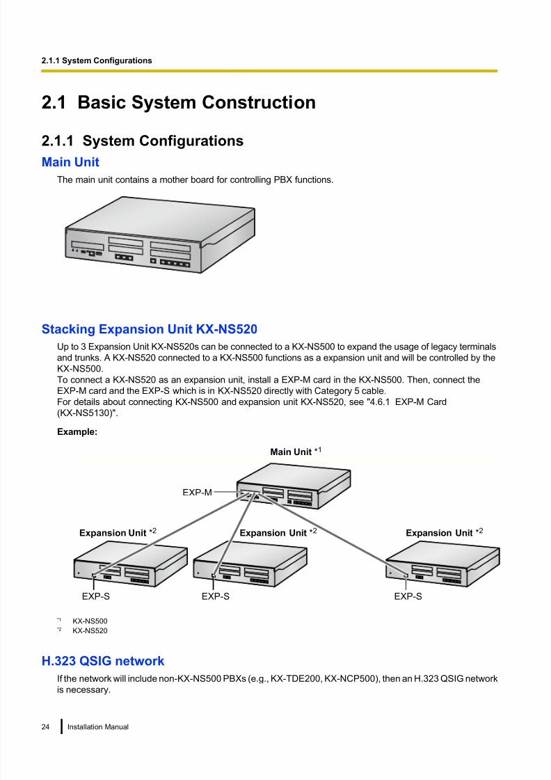
Main Unit
Front View Inside View (The top cover is removed.)
HD E GF I
CB A
A. Front cover plate for the EXP-M Slot
B. Front cover plates for Trunk/Doorphone Card Slots
C. Front cover plates for the Extension Card Slots
D. Extension Card Slot
E. Trunk/Doorphone Card Slot
F. EXP-M Card Slot
G. SD Card Slot
H. DSP Card Slot
I. RMT Card Slot
36 Installation Manual
2.3.3 System Capacity

8/18/2019 NS500 Installation Manual
http://slidepdf.com/reader/full/ns500-installation-manual 37/300
Expansion Unit
Front View Inside View (The top cover is removed.)
C D E
B A
A. Front cover plates for Trunk/Doorphone Card Slots
B. Front cover plates for the Extension Card Slots
C. Extension Card Slot
D. Trunk/Doorphone Card Slot
E. SD Card Slot (not available)
Installation Manual 37
2.3.3 System Capacity
8/18/2019 NS500 Installation Manual
http://slidepdf.com/reader/full/ns500-installation-manual 38/300
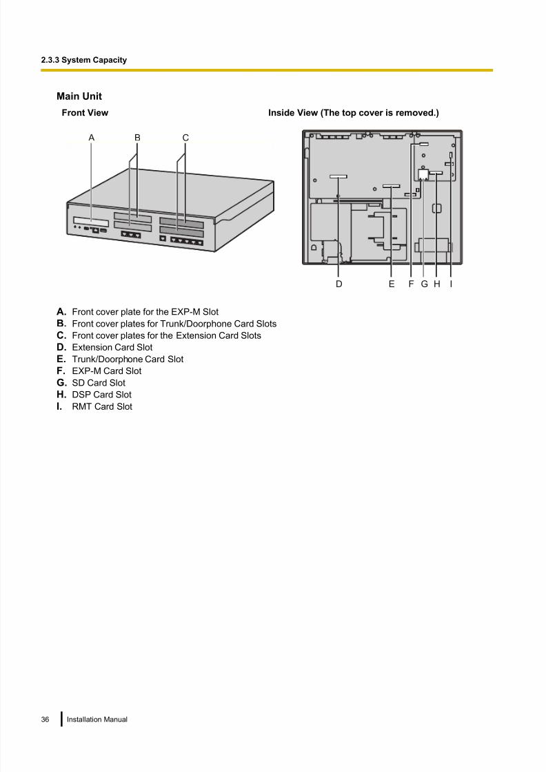
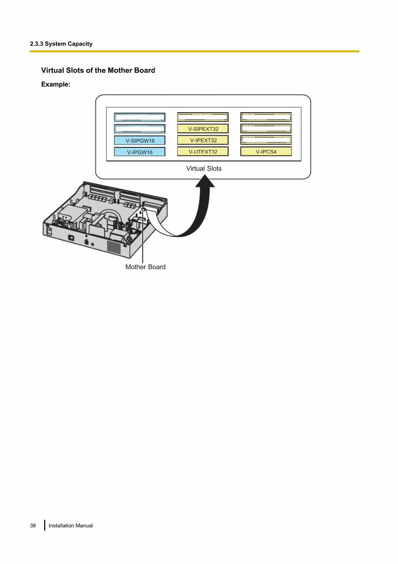
Virtual Slots of the Mother Board
Example:
Virtual Slots
V-SIPGW16
V-IPGW16
V-IPEXT32
V-UTEXT32
V-SIPEXT32
V-IPCS4
Mother Board
38 Installation Manual
2.3.3 System Capacity

8/18/2019 NS500 Installation Manual
http://slidepdf.com/reader/full/ns500-installation-manual 39/300
Maximum Optional Service Cards
The following number of card can be installed in the Physical Slots or Virtual Slots of the PBX.
Note• Any card that exceeds the capacity of the PBX will be ignored.
• When the PBX starts up with an invalid configuration, some cards will be ignored.
For KX-NS500 Physical Slot
Slot type Card Name Maximum Number
Pre-installed LCOT6 1
MCSLC16 1
DLC2 1DSP Card Slot 1
DSP S 1
DSP M 1
DSP L 1
SD Card Slot 1
SD XS 1
SD S 1
SD M 1
Remote Card Slot RMT 1
EXP-M Card Slot EXP-M 1
Trunk Slot*1 1
LCOT6 1
PRI30/E1 1
DPH2 1
Extension Slot*2 (Pattern 1) 2
DHLC4 2
DLC8 2
MCSLC8 2
(Pattern 2) 1
DLC16 1
MCSLC16 1
*1 You can install one DPH2 card and one of the Trunk card.*2 For Extension Slot, you need to select Pattern 1 or Pattern 2.
DLC16 or MCSLC16 card can be installed in first Extension Slot only.
Installation Manual 39
2.3.3 System Capacity

8/18/2019 NS500 Installation Manual
http://slidepdf.com/reader/full/ns500-installation-manual 40/300
If you install DLC16 or MCSLC16 card in first Extension slot, you cannot install DHLC4, DLC8 or MCSLC8 in the second Extension
slot.
Cards Installed in Virtual SlotsCard type Card Name Maximum Number
Virtual Trunk Card 4
V-IPGW16 2
V-SIPGW16 4
Virtual Extension Card 4
V-IPEXT32 4
V-SIPEXT32 4
V-UTEXT32 4
Virtual IP-CS Card V-IPCS4 4
For KX-NS520 Physical Slot
Slot type Card Name Maximum Number
Pre-installed MCSLC16 1
Trunk Slot DPH2 1
Trunk Slot 2
LCOT6 2
PRI30/E1 1
Extension Slot*1 (Pattern 1) 2
DHLC4 2
DLC8 2
MCSLC8 2
(Pattern 2) 1
DLC16 1
MCSLC16 1
*1 For Extension Slot, you need to select Pattern 1 or Pattern 2.
DLC16 or MCSLC16 card can be installed in first Extension Slot only.
If you install DLC16 or MCSLC16 card in first Extension slot, you cannot install DHLC4, DLC8 or MCSLC8 in the second Extension
slot.
40 Installation Manual
2.3.3 System Capacity

8/18/2019 NS500 Installation Manual
http://slidepdf.com/reader/full/ns500-installation-manual 41/300
Trunk Option Card Installing Restrictions
KX-NS500
2nd SlotLCOT6 PRI30/E1 DPH2
1st Slot
LCOT6 —*1 —*1 ü
PRI30/E1 —*1 —*1 ü
DPH2 ü ü —*1
*1 This installation combination is not available due to software restrictions.
KX-NS520
2nd Slot
LCOT6 PRI30/E1 DPH2
1st Slot
LCOT6 ü —*1 ü
PRI30/E1 —*1 —*1 ü
DPH2 ü ü —*1
*1 This installation combination is not available due to software restrictions.
Extension Option Card Installing RestrictionsKX-NS500/KX-NS520
2nd Slot
MCSLC16 MCSLC8 DLC16 DLC8 DHLC4
1st Slot
MCSLC16 —*1 —*1 —*1 —*1 —*1
MCSLC8 —*1 ü —*1 ü ü
DLC16 —*1 —*1 —*1 —*1 —*1
DLC8 —*1ü —*1
ü ü
DHLC4 —*1 ü —*1 ü ü
*1 This installation combination is not available due to software restrictions.
Installation Manual 41
2.3.3 System Capacity

8/18/2019 NS500 Installation Manual
http://slidepdf.com/reader/full/ns500-installation-manual 42/300
Maximum Trunks, Extensions, VMs, PFT ports and MOHs/Pagers
The PBX supports the following number of trunks and extensions.
Trunk KX-NS500(Pre-Installe
d)
KX-NS500(Maixmum)
KX-NS500w/1
KX-NS520
KX-NS500w/2
KX-NS520s
KX-NS500w/3
KX-NS520s
Total Number of
Trunks
6 100 130 160 190
Trunk (Physical
Trunk Card)
6 36 66 96 126
LCOT 6 12 24 36 48
PRI30 0 30 60 90 120
E1 0 30 60 90 120
Trunk (Virtual Trunk
Card)
0 64
H.323 Trunks 0 32
SIP Trunks 0 64
Total Number of
Extensions
18 162 (168) 194 (208) 226 (248) 258 (288)
Extension (Physical
Extension Card)
18 34 (40) 66 (80) 98 (120) 130 (160)
SLT 16 32 64 96 128
DPT (DXDP) 2 (4) 18 (24) 34 (48) 50 (72) 66 (96)
DPT (other) 0 8 16 24 32
APT 0 8 16 24 32
Extension (Virtual
Extension Card)
0 128
IP-PT and
Softphone
0 128
SIP Extension 0 128
SIP Phone 0 128
KX-UT
Series
0 128
42 Installation Manual
2.3.3 System Capacity
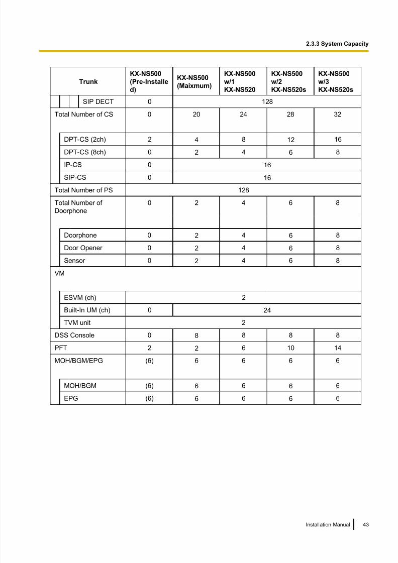
8/18/2019 NS500 Installation Manual
http://slidepdf.com/reader/full/ns500-installation-manual 43/300
Trunk
KX-NS500
(Pre-Installe
d)
KX-NS500
(Maixmum)
KX-NS500
w/1
KX-NS520
KX-NS500
w/2
KX-NS520s
KX-NS500
w/3
KX-NS520s
SIP DECT 0 128
Total Number of CS 0 20 24 28 32
DPT-CS (2ch) 2 4 8 12 16
DPT-CS (8ch) 0 2 4 6 8
IP-CS 0 16
SIP-CS 0 16
Total Number of PS 128
Total Number of
Doorphone
0 2 4 6 8
Doorphone 0 2 4 6 8
Door Opener 0 2 4 6 8
Sensor 0 2 4 6 8
VM
ESVM (ch) 2
Built-In UM (ch) 0 24
TVM unit 2
DSS Console 0 8 8 8 8
PFT 2 2 6 10 14
MOH/BGM/EPG (6) 6 6 6 6
MOH/BGM (6) 6 6 6 6
EPG (6) 6 6 6 6
Installation Manual 43
2.3.3 System Capacity

8/18/2019 NS500 Installation Manual
http://slidepdf.com/reader/full/ns500-installation-manual 44/300
DSP Resources
DSP cards provide digital signal processor (DSP) resources, and the PBX uses the resources to perform
various PBX operations. The following illustration shows the concept of DSP resource usage. More complex
situations may require additional resources, and in some cases the amount of DSP resources required maybe less than expected.
Conference
0.5
Outgoing Message(DISA)*3
2
1
Music on Hold (MOH)/
External Paging (EPG)*3
1
Internal MOH*3
Unified Messaging
1.3
PBX
Doorphone*2
3
1
AnalogueTrunk*2
2.2
G.729A
G.711
1
IP Trunk*1
2.2
G.729AG.711
1
IP-PT
1
SLT*2
1
PRI/E1*2
: Required DSP Resources
UM Tone Generator
2
Echo Canceller *3
3
2.2
G.729AG.711
1
IP-CS
PS
DPT/APT*2
1
*1 Connections that arrive over a stacking connection require the same amount of DSP resources as shown in this example.*2 DSP resources are used during conversations between legacy trunks/extensions/Doorphones and IP trunks/extensions.*3 DSP resources are used when IP trunks or IP extensions access these devices.
Required DSP Resources Assessment
The maximum number of simultaneous calls, operations and features using IP protocols is determined by the
DSP card installed in the PBX.
To decide how much resources are required for the PBX, the DSP Resource Advisor can be useful.
Note
• Calls cannot be made or received when all of the DSP resources are being used.
44 Installation Manual
2.3.3 System Capacity
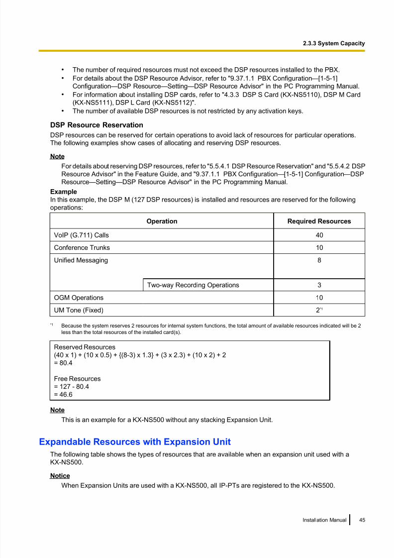
8/18/2019 NS500 Installation Manual
http://slidepdf.com/reader/full/ns500-installation-manual 45/300
• The number of required resources must not exceed the DSP resources installed to the PBX.
• For details about the DSP Resource Advisor, refer to "9.37.1.1 PBX Configuration—[1-5-1]
Configuration—DSP Resource—Setting—DSP Resource Advisor" in the PC Programming Manual.
• For information about installing DSP cards, refer to "4.3.3 DSP S Card (KX-NS5110), DSP M Card(KX-NS5111), DSP L Card (KX-NS5112)".
• The number of available DSP resources is not restricted by any activation keys.
DSP Resource Reservation
DSP resources can be reserved for certain operations to avoid lack of resources for particular operations.
The following examples show cases of allocating and reserving DSP resources.
Note
For details about reserving DSP resources, refer to "5.5.4.1 DSP Resource Reservation" and "5.5.4.2 DSP
Resource Advisor" in the Feature Guide, and "9.37.1.1 PBX Configuration—[1-5-1] Configuration—DSP
Resource—Setting—DSP Resource Advisor" in the PC Programming Manual.
Example
In this example, the DSP M (127 DSP resources) is installed and resources are reserved for the following
operations:
Operation Required Resources
VoIP (G.711) Calls 40
Conference Trunks 10
Unified Messaging 8
Two-way Recording Operations 3
OGM Operations 10
UM Tone (Fixed) 2*1
*1 Because the system reserves 2 resources for internal system functions, the total amount of available resources indicated will be 2
less than the total resources of the installed card(s).
Reserved Resources
(40 x 1) + (10 x 0.5) + {(8-3) x 1.3} + (3 x 2.3) + (10 x 2) + 2
= 80.4
Free Resources
= 127 - 80.4
= 46.6
Note
This is an example for a KX-NS500 without any stacking Expansion Unit.
Expandable Resources with Expansion Unit
The following table shows the types of resources that are available when an expansion unit used with a
KX-NS500.
Notice
When Expansion Units are used with a KX-NS500, all IP-PTs are registered to the KX-NS500.
Installation Manual 45
2.3.3 System Capacity

8/18/2019 NS500 Installation Manual
http://slidepdf.com/reader/full/ns500-installation-manual 46/300
Type Resource Availability
Optional Service Card Physical Card for Legacy Trunks and Extensions ü
Virtual Card –*1
RMT Card –
DPH Card ü
DSP Card –
Terminal DPT/APT/SLT ü
PT-interface CS ü
PS ü
IP-CS/IP-PT/KX-UT Series SIP Phone/SIP-CS –*1
Doorphone ü
IP Softphone –*1
Activation Key Any Activation key –
*1 IP terminals, except for KX-NT265 (software version 2.00 or later only), are registered and controlled by the KX-NS500.
46 Installation Manual
2.3.3 System Capacity

8/18/2019 NS500 Installation Manual
http://slidepdf.com/reader/full/ns500-installation-manual 47/300
Section 3
Information about the Activation Keys
This section provides information on activation keys,
including how to obtain activation keys.
Installation Manual 47

8/18/2019 NS500 Installation Manual
http://slidepdf.com/reader/full/ns500-installation-manual 48/300
3.1 Information about the Activation Keys Activation keys are required to use IP trunks and IP telephones on a private IP network with a KX-NS500. Also,
to upgrade the software to use enhanced features, the corresponding activation keys for that feature arerequired. Some activation keys are provided by default, some are provided free for a limited period, and others
are provided separately as activation key files.
3.1.1 Type and Maximum Number of Activation Keys
The PBX supports the following type and number of activation keys. The preinstalled activation keys on the
mother board are shown with "[ ]".
When the number of preinstalled activation keys is not enough for the desired configuration or when you wish
to use enhanced features, additional activation keys in the form of activation key files can be installed using
Web Maintenance Console.
Note
• Store the downloaded activation key files in your PC or a memory device. They can then be reinstalled
in an emergency situation.
• For information about how to obtain the additional activation keys, refer to "3.1.2 Activation Key Code
and Key Management System".
• For information about how to install the activation key files using Web Maintenance Console, refer to
"5.4.4 Installing Additional Activation Keys".
IP Trunks
Model No. Activation Key Type Description Maximum IP Trunks
KX-NSM102 2 IP Trunk Allows the use of 2 IP trunks (H.
323/SIP).
64 IP trunks
(H.323/SIP)*1*2
KX-NSM104 4 IP Trunk Allows the use of 4 IP trunks (H.
323/SIP).
KX-NSM108 8 IP Trunk Allows the use of 8 IP trunks (H.
323/SIP).
KX-NSM116 16 IP Trunk Allows the use of 16 IP trunks (H.
323/SIP).
*1 You need to set the number of installed activation keys to be used for H.323 trunks through system programming. By default, all
installed activation keys will be used for SIP trunks.*2 The maximum number of IP trunks for H.323 is 32.
48 Installation Manual
3.1.1 Type and Maximum Number of Activation Keys

8/18/2019 NS500 Installation Manual
http://slidepdf.com/reader/full/ns500-installation-manual 49/300
IP Telephone Capacity
Model No. Activation Key Type DescriptionMaximum IP
Telephones
KX-NSM201 1 IPSoftphone/IP PT Allows the use of 1 IP-PT/IP
softphone/KX-UT series SIP
phone.
Total 128 IP-PTs/IP
softphones/KX-UT
series SIP phones*1
KX-NSM205 5 IPSoftphone/IP PT Allows the use of 5 IP-PTs/IP
softphones/KX-UT series SIP
phones.
KX-NSM210 10 IPSoftphone/IP PT Allows the use of 10 IP-PTs/IP
softphones/KX-UT series SIP
phones.
KX-NSM220 20 IPSoftphone/IP PT Allows the use of 20 IP-PTs/IP
softphones/KX-UT series SIPphones.
KX-NSM501 1 IP PT Allows the use of 1 IP-PT/
KX-UT series SIP phone.
Total 128 IP-PTs/
KX-UT series SIP
phones
[4 IP-PTs/KX-UT
series SIP phones]*2
KX-NSM505 5 IP PT Allows the use of 5 IP-PTs/
KX-UT series SIP phones.
KX-NSM510 10 IP PT Allows the use of 10 IP-PTs/
KX-UT series SIP phones.
KX-NSM520 20 IP PT Allows the use of 20 IP-PTs/
KX-UT series SIP phones.
KX-NSM701 1 SIP Extension Allows the use of 1 IPConferencing Phone/third party
SIP phone.
Total 128 IP
Conferencing Phones/
third party SIP phones
KX-NSM705 5 SIP Extension Allows the use of 5 IP
Conferencing Phones/third party
SIP phones.
KX-NSM710 10 SIP Extension Allows the use of 10 IP
Conferencing Phones/third party
SIP phones.
KX-NSM720 20 SIP Extension Allows the use of 20 IP
Conferencing Phones/third party
SIP phones.
*1 You can set how many IP softphones can be used with the installed activation keys through system programming. By default, only
IP softphones can be used with the installed activation keys.*2 The capacity given in [square brackets] shows the number of activation keys preinstalled on the mother board.
Networking
Model No. Activation Key Type DescriptionMaximum Activation
Keys
KX-NSN002 QSIG Network Allows the use of enhanced
QSIG network features (NDSS,Centralised Voice Mail, etc.). 1 activation key
Installation Manual 49
3.1.1 Type and Maximum Number of Activation Keys

8/18/2019 NS500 Installation Manual
http://slidepdf.com/reader/full/ns500-installation-manual 50/300
Feature Guide References for Related Features of Activation Keys
QSIG Network
• 4.2.1.4 Common Extension Numbering for 2 PBXs
• 4.2.2.2 Common Extension Numbering for Multiple PBXs
• 4.2.5 QSIG Enhanced Features
• 4.2.5.1 Network Direct Station Selection (NDSS)
• 4.2.5.2 Centralised Voice Mail
Unified Messaging System (Features)
Model No. Activation Key Type DescriptionMaximum Activation
Keys
KX-NSU002 Two-way REC Control Allows a manager/administrator to use the Automatic Two-way
Recording feature to record other
users.
1 activation key
KX-NSU003 Message Backup Allows the automatic backup of
messages.1 activation key
Feature Guide References for Related Features of Activation Keys
Two-way REC Control
3.2.1.4 Automatic Two-way Recording for Manager
Message Backup3.1.2.5 System Backup/Restore
Unified Messaging System (Unified Messaging Ports)
Model No. Activation Key Type DescriptionMaximum Unified
Messaging Ports
KX-NSU102 2 UM Port Allows the use of 2 Unified
Messaging ports.24 Unified Messaging
ports
[2 Unified Messaging
ports]KX-NSU104 4 UM Port Allows the use of 4 Unified
Messaging ports.
Feature Guide References for Related Features of Activation Keys
3.1.1 Unified Messaging System Overview
50 Installation Manual
3.1.1 Type and Maximum Number of Activation Keys
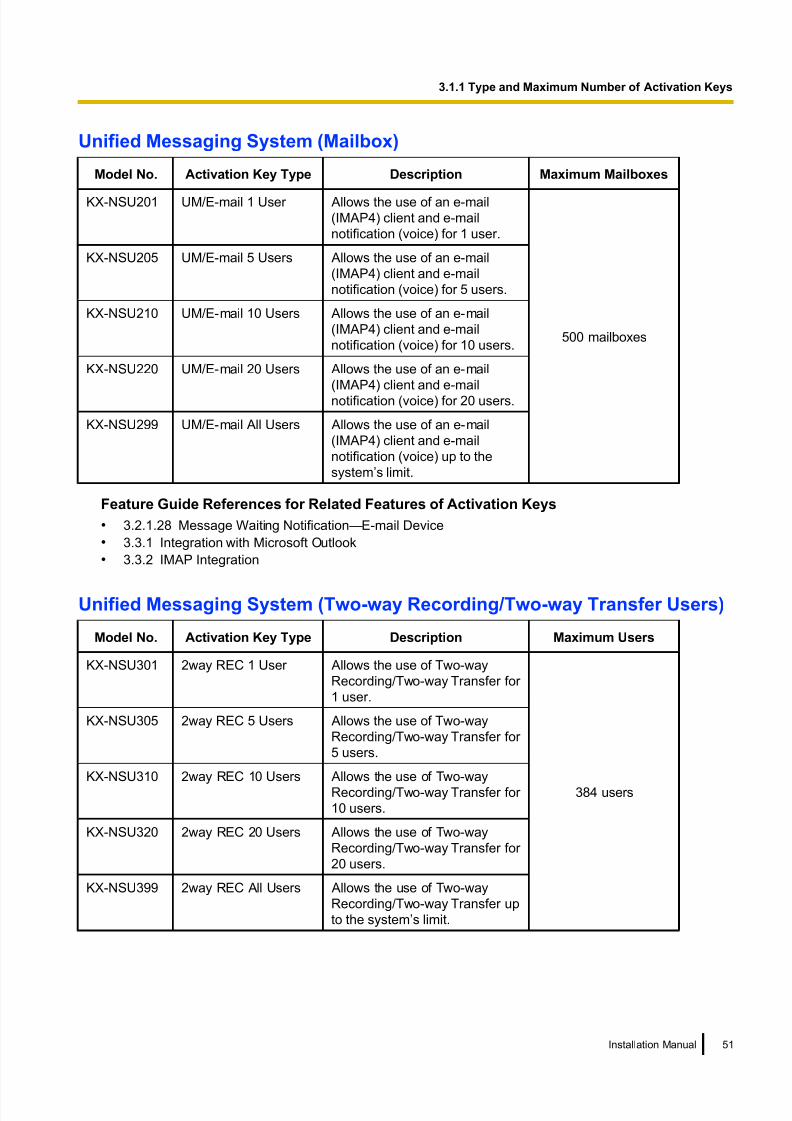
8/18/2019 NS500 Installation Manual
http://slidepdf.com/reader/full/ns500-installation-manual 51/300
Unified Messaging System (Mailbox)
Model No. Activation Key Type Description Maximum Mailboxes
KX-NSU201 UM/E-mail 1 User Allows the use of an e-mail
(IMAP4) client and e-mail
notification (voice) for 1 user.
500 mailboxes
KX-NSU205 UM/E-mail 5 Users Allows the use of an e-mail
(IMAP4) client and e-mail
notification (voice) for 5 users.
KX-NSU210 UM/E-mail 10 Users Allows the use of an e-mail
(IMAP4) client and e-mail
notification (voice) for 10 users.
KX-NSU220 UM/E-mail 20 Users Allows the use of an e-mail
(IMAP4) client and e-mail
notification (voice) for 20 users.
KX-NSU299 UM/E-mail All Users Allows the use of an e-mail
(IMAP4) client and e-mail
notification (voice) up to the
system’s limit.
Feature Guide References for Related Features of Activation Keys
• 3.2.1.28 Message Waiting Notification—E-mail Device
• 3.3.1 Integration with Microsoft Outlook
• 3.3.2 IMAP Integration
Unified Messaging System (Two-way Recording/Two-way Transfer Users)
Model No. Activation Key Type Description Maximum Users
KX-NSU301 2way REC 1 User Allows the use of Two-way
Recording/Two-way Transfer for
1 user.
384 users
KX-NSU305 2way REC 5 Users Allows the use of Two-way
Recording/Two-way Transfer for
5 users.
KX-NSU310 2way REC 10 Users Allows the use of Two-way
Recording/Two-way Transfer for
10 users.
KX-NSU320 2way REC 20 Users Allows the use of Two-way
Recording/Two-way Transfer for
20 users.
KX-NSU399 2way REC All Users Allows the use of Two-way
Recording/Two-way Transfer up
to the system’s limit.
Installation Manual 51
3.1.1 Type and Maximum Number of Activation Keys

8/18/2019 NS500 Installation Manual
http://slidepdf.com/reader/full/ns500-installation-manual 52/300
Feature Guide References for Related Features of Activation Keys
3.2.2.30 Two-way Record/Two-way Transfer
Cellular Phone Extension
Model No. Activation Key Type DescriptionMaximum Cellular
Phone Extensions
KX-NSE101 1 Mobile User Allows the use of 1 cellular phone
extension.
384 cellular phone
extensions
KX-NSE105 5 Mobile Users Allows the use of 5 cellular phone
extensions.
KX-NSE110 10 Mobile Users Allows the use of 10 cellular
phone extensions.
KX-NSE120 20 Mobile Users Allows the use of 20 cellular phone extensions.
Feature Guide References for Related Features of Activation Keys
• 2.2.2.3 Outside Destinations in Incoming Call Distribution Group
• 2.3.2 Call Forwarding (FWD)
• 2.16.1 Direct Inward System Access (DISA)
• 2.27.1 Cellular Phone Features—SUMMARY
• 4.2.6 Network ICD Group
• 4.2.6.1 PS Roaming by Network ICD Group
Communication Assistant (CA) User
Model No.Activation
Key TypeDescription
Maximum Activation
Keys
KX-NSA010 CA Thin
Client
Allows the use of CA Client in a thin-client
environment.1
KX-NSA020 CSTA
Multiplexer
Allows the use of CSTA Multiplexer.4
52 Installation Manual
3.1.1 Type and Maximum Number of Activation Keys

8/18/2019 NS500 Installation Manual
http://slidepdf.com/reader/full/ns500-installation-manual 53/300
Model No.Activation
Key TypeDescription
Maximum Activation
Keys
KX-NSA201 CA Pro 1
user
Allows the use of CA Client Pro for 1 user.*1
240*2
users without CAserver
(Max. 384*3 users with
CA server)
KX-NSA205 CA Pro 5
users
Allows the use of CA Client Pro for 5 users.*1
KX-NSA210 CA Pro 10
users
Allows the use of CA Client Pro for 10 users.*1
KX-NSA240 CA Pro 40
users
Allows the use of CA Client Pro for 40 users.*1
KX-NSA249 CA Pro 128
users
Allows the use of CA Client Pro for 128
users.*1
KX-NSA301 CA
Supervisor
Allows the use of CA Client Supervisor for 1
user.
KX-NSA401 CA Console Allows the use of CA Client Operator Console
for 1 user.
KX-NSA901 CA Network
1 user
Allows the use of CA Server network features
for 1 user.
KX-NSA905 CA Network
5 users
Allows the use of CA Server network features
for 5 users.
KX-NSA910 CA Network
10 users
Allows the use of CA Server network features
for 10 users.
KX-NSA940 CA Network40 users Allows the use of CA Server network featuresfor 40 users.
KX-NSA949 CA Network
128 users
Allows the use of CA Server network features
for 128 users.
*1 A maximum of 384 CA users can be registered. However, CA Server is necessary to register more than 240 CA users.*2 The maximum number of Supervisor users without CA server is 4 users.*3 The maximum number of Operator Console and Supervisor users combined when CA Server is used is 128 users.
CTI Licence
Model No. Activation Key Type DescriptionMaximum Activation
Keys
KX-NSF101 CTI interface Allows the use of the 3rd Party
CTI interface.1
Feature Guide References for Related Features of Activation Keys
2.26.1 Computer Telephony Integration (CTI)
Preinstalled Activation Keys in the Mother Board
Preinstalled activation keys with no expiration dateThe following type and number of activation keys are preinstalled on the mother board.
Installation Manual 53
3.1.1 Type and Maximum Number of Activation Keys

8/18/2019 NS500 Installation Manual
http://slidepdf.com/reader/full/ns500-installation-manual 54/300
Activation Key Activated Features
CA Basic-Express No Limit
IP Proprietary Telephone (ch) 4 IP-PTs/KX-UT series SIP phones
UM Port (ch) 2 Unified Messaging ports
Example: Preinstalled Activation Keys in the Mother Board
Preinstalled activation keys for free trial
The following activation keys are preinstalled on the mother board for the 60-days free trial. They will expire
60 days after pressing the Activate Pre-installed Activation key button to begin the free trial.
Activation Key Activated Features
Two-way Recording Control Automatic Two-way Recording feature
Message Backup Automatic backup of messages
UM/E-mail (128 user) 128 mailboxes
Two-Way Recording (30 users) 30 Two-way Recording/Two-way Transfer users
Mobile Extension (30 users) 30 cellular phone extensions
CA PRO (128 users) 128 CA Pro users
CA Supervisor (1 user) 1 CA Supervisor user
CA Operator Console (1 user) 1 CA Console user
CA Thin Client Server Use CA in a thin-client environment
CSTA Multiplexer Multiplexing for CSTA connections
CTI interface 3rd Party CTI interface
Call Centre Feature Enhancement Built-in ACD Report, Announcement of waiting
number for queuing
Activation Key Installation Example
The following illustration shows an example of when using 16 SIP trunks, 16 H.323 trunks, 40 IP-PTs, 20 IP
softphones, and 20 KX-UT series SIP phones on a private IP network using the mother board.
54 Installation Manual
3.1.1 Type and Maximum Number of Activation Keys

8/18/2019 NS500 Installation Manual
http://slidepdf.com/reader/full/ns500-installation-manual 55/300
Example:
Mother Board
Virtual Slots
V-SIPGW16
V-IPGW16
V-IPEXT32
V-UTEXT32
Desired Item:
16 SIP trunks
Required Activation Key:
KX-NSM116
Desired Item:
16 H.323 trunksRequired Activation Key:
KX-NSM116
Desired Item:
40 IP-PTs
20 IP softphones
Required Activation Key:
2 of KX-NSM520s
KX-NSM220
Desired Item:
20 KX-UT series
SIP phones
Required Activation Key:
KX-NSM720
Installation Manual 55
3.1.1 Type and Maximum Number of Activation Keys

8/18/2019 NS500 Installation Manual
http://slidepdf.com/reader/full/ns500-installation-manual 56/300
3.1.2 Activation Key Code and Key Management System
To obtain additional activation keys, you need to purchase the appropriate activation key codes and access
the Key Management System. You can download the activation keys as an activation key file from the Key
Management System.
To download the activation keys, enter the MPR ID number shown on the back of the main unit, and activation
key number and registration ID provided on each activation key code.
For information about the type of activation key codes available, refer to "3.1.1 Type and Maximum Number
of Activation Keys".
For details about installing the downloaded activation key file(s) in the PBX memory using Web Maintenance
Console, refer to "5.4.4 Installing Additional Activation Keys".
Note
• You can only download the activation key file once using the activation key number and registration ID
provided on the activation key code.
• Up to 8 activation keys can be downloaded as one activation key file.
• Up to 997 activation key files can be installed in the PBX memory.
• It is possible to send the activation key file to a specified e-mail address at the same time as
downloading it to a PC.
• Make sure to backup the downloaded activation key files on your PC.
• When the mother board has to be replaced due to a system malfunction, the MPR ID for the mother
board is no longer valid. In this case, you need a temporary activation key for maintenance purposes.
The temporary activation key can only be used for a limited time period, and can be downloaded from
the Key Management System in the same way as downloading activation key files.
56 Installation Manual
3.1.2 Activation Key Code and Key Management System

8/18/2019 NS500 Installation Manual
http://slidepdf.com/reader/full/ns500-installation-manual 57/300
3.1.3 Using CTI Applications
To use CTI applications with the KX-NS500, KX-NSF101 (CTI interface) is required. One KX-NSF101 supports
one CTI application. However, Communication Assistant (CA) Server does not require KX-NSF101.
In the example below, one KX-NSF101 is required for using one CTI application.
Example 1
PBX
Single CSTA
Connection CTI Server
In the example below, an activation key is not required to use CA Server.
Example 2
PBX
Single CSTA
Connection CA Server
To use 2 or more CTI applications, the CSTA Multiplexer application is required, along with one KX-NSA020
(CSTA Multiplexer) for each CTI application. KX-NSF101 is included in KX-NSA020. Therefore, when
KX-NSA020 is installed, KX-NSF101 is not required.
In the example below, three KX-NSA020 are required for three CTI applications. (CA Server does not require
a KX-NSA020.)
Installation Manual 57
3.1.3 Using CTI Applications

8/18/2019 NS500 Installation Manual
http://slidepdf.com/reader/full/ns500-installation-manual 58/300
Example 3
PBX
Single CSTA
Connection
CTI Application Server
Panasonic
CSTA Multiplexer
CTI Application Server
CTI Application Server
CA Server
Note
• Up to 4 CTI application servers can be used at the same time when using a CSTA multiplexer.• An Activation Key for Multiple CSTA Connection (KX-NSA020) is required for each CTI application.
• When a 3rd party CSTA multiplexer is used, a CTI interface activation key (KX-NSF101) is required
for the CSTA connection. (In this case, Activation Key for Multiple CSTA Connection [KX-NSA020] is
not required.)
• For details regarding KX-NSF101, refer to "CTI Licence" in "3.1.1 Type and Maximum Number of
Activation Keys".
• For details regarding KX-NSA020, refer to "Communication Assistant (CA) User" in "3.1.1 Type and
Maximum Number of Activation Keys".
58 Installation Manual
3.1.3 Using CTI Applications

8/18/2019 NS500 Installation Manual
http://slidepdf.com/reader/full/ns500-installation-manual 59/300
Section 4
Installation
This section describes the procedures to install the
PBX. Detailed instructions for planning the installation
site, installing the main unit and optional service cards,
and cabling of peripheral equipment are provided.
Further information on peripheral equipment installation
is included.
Installation Manual 59

8/18/2019 NS500 Installation Manual
http://slidepdf.com/reader/full/ns500-installation-manual 60/300
4.1 Before Installation
4.1.1 Before InstallationPlease read the following notes concerning installation and connection before installing the PBX and terminal
equipment.
Be sure to comply with all applicable laws, regulations, and guidelines.
Notice
Panasonic assumes no responsibility for injuries or property damage resulting from failures arising out of
improper installation or operation inconsistent with this documentation.
Safety Installation Instructions
WARNINGWhen installing telephone wiring, basic safety precautions should always be followed to reduce
the risk of fire, electric shock and injury to persons, including the following:
• Never install telephone wiring during a lightning storm.
• Never install telephone jacks in wet locations unless the jack is specifically designed for wet
locations.
• Never touch uninsulated telephone wires or terminals unless the telephone line has been
disconnected at the network interface.
• Use caution when installing or modifying telephone lines.
• Anti-static precautions should be taken during installation.
Installation PrecautionsThe PBX is suitable for mounting on a 19-inch rack, mounting on a wall, or placing on a desktop, and should
be installed in a location where it is accessible for inspections and maintenance.
To prevent malfunction, noise, or discolouration, follow the instructions below:
WARNING
Do not install the system in the following locations:
• Areas where shocks or vibrations are frequent or strong. Such activity may lead to the product
falling over and causing injury, or may impair the product’s performance.
• Areas with high amounts of dust. High amounts of dust can lead to fire or electric shock, and
impair the performance of the product.
CAUTION
Do not install the system in the following locations:
• In direct sunlight and hot, cold, or humid places. (Temperature range: 0 °C to 40 °C)
• Areas where sulphuric gases may be present, such as near thermal springs.
• Near devices that generate high frequencies, such as sewing machines or electric welders.
• Locations where other objects will obstruct the area around the PBX. Be especially careful to leave at
least 5 cm to the sides of the PBX for ventilation.
• Locations where condensation can occur.
Notice
Do not install the system in the following locations:
60 Installation Manual
4.1.1 Before Installation

8/18/2019 NS500 Installation Manual
http://slidepdf.com/reader/full/ns500-installation-manual 61/300
• On or near computers, or other office equipment, as well as microwave ovens or air conditioners. (It is
preferable not to install the system in the same room as the above equipment.)
• Within 1.8 m of radios and televisions. (Both the PBX and PTs should be at least 1.8 m away from such
devices.)
Do not perform the following:
• Do not block the openings of the PBX.
• Do not stack up the optional service cards.
Wiring Precautions
Be sure to follow these instructions when wiring the unit:
CAUTION
• Avoid using the same AC outlet for computers and other office equipment, as noise generated by such
equipment may hamper system performance or interrupt the system.
• Unplug the system from its power source when wiring, and plug the system back in only after all wiringis completed.
• Trunks should be installed with surge protectors. For details, refer to "4.2.11 Surge Protector
Installation".
Notice
• Use 1-pair telephone cables when connecting SLTs, data terminals, answering machines, computers,
etc.
• Mis-wiring may cause the PBX to operate improperly. Refer to "Section 4 Installation" when wiring
the system.
• If an extension does not operate properly, disconnect the telephone from the extension line and connect
it again, or turn off the PBX using the power switch, then turn it on again.
• Use twisted pair cable for trunk connection.• To prevent signal noise from interfering with the performance of the product, do not run unshielded
telephone cables near AC power cables, computer cables, AC power sources, etc. When running
cables near other noise-generating devices or cables, use shielded telephone cables or shield the
telephone cables with metal tubing.
Preparing the Network Environment
Be sure to prepare your network’s environment for the installation of the PBX according to the intended PBX
networking configuration. For details about PBX network configurations, refer to "Section 8 Networking
Information".
Installation Manual 61
4.1.1 Before Installation

8/18/2019 NS500 Installation Manual
http://slidepdf.com/reader/full/ns500-installation-manual 62/300
4.2 Installation of the PBX
4.2.1 UnpackingKX-NS500
Unpack the box and check the items below:
• Main unit
• CD-ROM(s)*1
• AC power cord*2
• Hook clip
• 19-inch rack attachment bracket x 2
• Screw x 6 (For 19 inch rack)
• Screw x 3 (For Wall Mounting)
• Washer x 3 (For Wall Mounting)*1 The number of included CD-ROMs varies according to the country/area.*2 The KX-NS500LA is supplied with 2 types of AC power cord. Please use whichever is appropriate for the country/area.
KX-NS520
Unpack the box and check the items below:
• Expansion unit
• CD-ROM(s)*1
• AC power cord*2
• Hook clip
• Ferrite core x 2
• 19-inch rack attachment bracket x 2
• Screw x 6 (For 19 inch rack)• Screw x 3 (For Wall Mounting)
• Washer x 3 (For Wall Mounting)*1 The number of included CD-ROMs varies according to the country/area.*2 The KX-NS520LA is supplied with 2 types of AC power cord. Please use whichever is appropriate for the country/area.
62 Installation Manual
4.2.1 Unpacking

8/18/2019 NS500 Installation Manual
http://slidepdf.com/reader/full/ns500-installation-manual 63/300
4.2.2 Names and Locations
KX-NS500
Front Back/Inside
C D
B F G H P Q R S TO U
I J KLE A M N
A. STATUS Indicator
B. PBX MODE indicator (Unused)
C. System Mode Switch
D. LAN Port
E. USB Port
F. LCOT Ports
G. DPT Port
H. SLT Ports
I. EXP-M slot
J. Trunk/Doorphone Free Slot
K. Extension Free Slot
L. Top Cover
M. Sub Board
N. Main Board
O. FG Terminal
P. AC Inlet
Q. Power Switch
R. MPR ID
S. External Battery
T. Battery SwitchU. FAN
Installation Manual 63
4.2.2 Names and Locations

8/18/2019 NS500 Installation Manual
http://slidepdf.com/reader/full/ns500-installation-manual 64/300
KX-NS520
Front Back/Inside
C D K L M N OJ P
E FGB A H I
A. STATUS Indicator
B. EXT-S Port
C. PFT Port
D. SLT Slot
E. Trunk/Doorphone Free Slot
F. Extension Free Slot
G. Top Cover
H. Sub Board
I. Main Board
J. FG Terminal
K. AC Inlet
L. Power Switch
M. MPR ID
N. External Battery
O. Battery Switch
P. FAN
64 Installation Manual
4.2.2 Names and Locations

8/18/2019 NS500 Installation Manual
http://slidepdf.com/reader/full/ns500-installation-manual 65/300
4.2.3 Opening/Closing the Top Cover
Opening the Top Cover
KX-NS500/KX-NS520
CAUTION
When opening the top cover, the power switch must be turned off.
1. Confirm that the power switch is turned off and pull the power cable.
Power Switch
Note
In order to turn off the PBX’s power, a system shutdown using Web Maintenance Console must first
be performed. For details, refer to "5.4 System Control—System Shutdown" in the PC Programming
Manual.
2. Turn the screws anticlockwise to loosen.
Installation Manual 65
4.2.3 Opening/Closing the Top Cover

8/18/2019 NS500 Installation Manual
http://slidepdf.com/reader/full/ns500-installation-manual 66/300
3. Slide the top cover then lift it off.
Closing the Top Cover 1. Place the top cover onto the PBX. Then slide the top cover until it closes properly.
2. Turn the screws clockwise to tighten.
CAUTION
For safety reasons, close the top cover and tighten the screws before operating the PBX.
66 Installation Manual
4.2.3 Opening/Closing the Top Cover

8/18/2019 NS500 Installation Manual
http://slidepdf.com/reader/full/ns500-installation-manual 67/300
4.2.4 Frame Earth Connection
KX-NS500/KX-NS520
1. Loosen the screw.
2. Insert an earthing wire (user-supplied).
3. Tighten the screw.
4. Connect the earthing wire to earth.
To earth
Screw
Earthing wire
WARNING
• Proper earthing (connection to earth) is very important to reduce the risk to the user of
electrocution or to protect the PBX from the bad effects of external noise in the case of a
lightning strike.
• The earthing wire of the AC cable has an effect against external noise and lightning strikes, but
it may not be enough to protect the PBX and to ensure electromagnetic compatibility. A
permanent connection between earth and the earth terminal of the PBX must be made.
CAUTION
For earthing wire, green-and-yellow insulation is required, and the cross-sectional area of the conductor
must be more than 0.75 mm2 or 18 AWG.
Notice
Be sure to comply with applicable local regulations (e.g., laws, guidelines).
Installation Manual 67
4.2.4 Frame Earth Connection

8/18/2019 NS500 Installation Manual
http://slidepdf.com/reader/full/ns500-installation-manual 68/300
4.2.5 Installing/Removing the Optional Service Cards
CAUTION
• Before touching the product (PBX, cards, etc.), discharge static electricity by touching ground or wearing an earthing strap. Failure to do so may cause the PBX to malfunction due to static electricity.
• When installing or removing the optional service cards, the power switch must be turned off.
• When installing or removing the optional service cards, do not put pressure on any parts of the mother
board. Doing so may result in damage to the PBX.
Note
Make sure the AC power cord is not connected to the AC inlet of the PBX.
68 Installation Manual
4.2.5 Installing/Removing the Optional Service Cards

8/18/2019 NS500 Installation Manual
http://slidepdf.com/reader/full/ns500-installation-manual 69/300
Installing a DSP Card in a DSP Card Slot
1. Place the front end of the card under the hook, and then lower the rear end of the card so that the holes
of the card are aligned with the screw holes.
Installation Manual 69
4.2.5 Installing/Removing the Optional Service Cards

8/18/2019 NS500 Installation Manual
http://slidepdf.com/reader/full/ns500-installation-manual 70/300
2. Insert the screws into the holes on the card, and tighten the screws to secure the card.
Screws
Removing a DSP Card Installed in the DSP Card Slot
1. Loosen and remove the screws.
Screws
70 Installation Manual
4.2.5 Installing/Removing the Optional Service Cards
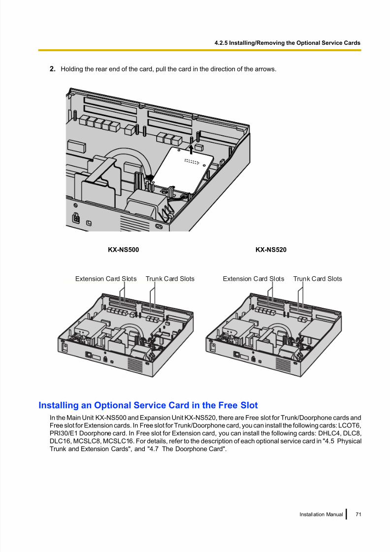
8/18/2019 NS500 Installation Manual
http://slidepdf.com/reader/full/ns500-installation-manual 71/300
2. Holding the rear end of the card, pull the card in the direction of the arrows.
KX-NS500 KX-NS520
Extension Card Slots Trunk Card Slots Extension Card Slots Trunk Card Slots
Installing an Optional Service Card in the Free Slot
In the Main Unit KX-NS500 and Expansion Unit KX-NS520, there are Free slot for Trunk/Doorphone cards and
Free slot for Extension cards. In Free slot for Trunk/Doorphone card, you can install the following cards: LCOT6,
PRI30/E1 Doorphone card. In Free slot for Extension card, you can install the following cards: DHLC4, DLC8,
DLC16, MCSLC8, MCSLC16. For details, refer to the description of each optional service card in "4.5 Physical
Trunk and Extension Cards", and "4.7 The Doorphone Card".
Installation Manual 71
4.2.5 Installing/Removing the Optional Service Cards

8/18/2019 NS500 Installation Manual
http://slidepdf.com/reader/full/ns500-installation-manual 72/300
1. Remove the front cover plate for the Free slot.
Dummy Cover Plate
72 Installation Manual
4.2.5 Installing/Removing the Optional Service Cards

8/18/2019 NS500 Installation Manual
http://slidepdf.com/reader/full/ns500-installation-manual 73/300
2. Position the card in the open slot, making sure that the tabs on the both sides of the card fit into place.
Then, holding the card firmly in place, lower the rear end so that the holes of the card are aligned with the
screw holes.
Installation Manual 73
4.2.5 Installing/Removing the Optional Service Cards

8/18/2019 NS500 Installation Manual
http://slidepdf.com/reader/full/ns500-installation-manual 74/300
3. Insert the spacers into the holes on the card, and tighten the spacers to secure the card.
Spacer
Note
When using larger sized cards with smaller sized cards, install the larger sized cards in the bottom.
4. Connect cables to appropriate ports of the card. For details about pin assignments, refer to the appropriate
section in "4.5 Physical Trunk and Extension Cards".
Note
Make sure to connect cables after installing the card in the PBX, not before.
74 Installation Manual
4.2.5 Installing/Removing the Optional Service Cards

8/18/2019 NS500 Installation Manual
http://slidepdf.com/reader/full/ns500-installation-manual 75/300
Removing Optional Service Card from the Free Slot
1. Loosen and remove the spacers.
Spacer
2. Holding the rear end of the card, pull the card in the direction of the arrows.
Installation Manual 75
4.2.5 Installing/Removing the Optional Service Cards

8/18/2019 NS500 Installation Manual
http://slidepdf.com/reader/full/ns500-installation-manual 76/300
Installing the EXP-M Card in the EXP-M Card slot
1. Remove the front cover plate for the EXP-M card.
Dummy Cover Plate
76 Installation Manual
4.2.5 Installing/Removing the Optional Service Cards

8/18/2019 NS500 Installation Manual
http://slidepdf.com/reader/full/ns500-installation-manual 77/300
2. Position the card in the EXP-M card slot, making sure that the extension bolts are aligned with the holes
in the card and that the tabs on both sides of the card fit into place. Then, holding the card firmly in place,
lower the rear end so that the holes of the card are aligned with the extension bolts.
Installation Manual 77
4.2.5 Installing/Removing the Optional Service Cards

8/18/2019 NS500 Installation Manual
http://slidepdf.com/reader/full/ns500-installation-manual 78/300
3. Insert the screws into the holes on the card, and tighten the screws to secure the card.
Screws
4. Connect cables to the appropriate ports of the card. For details about pin assignments, refer to the
appropriate section in "4.6.1 EXP-M Card (KX-NS5130)".
Note
Make sure to connect the cables after installing the card in the PBX, not before.
Removing the EXP-M Card from the EXP-M Card slot
1. Loosen and remove the screws.
Screws
78 Installation Manual
4.2.5 Installing/Removing the Optional Service Cards

8/18/2019 NS500 Installation Manual
http://slidepdf.com/reader/full/ns500-installation-manual 79/300
2. Holding the rear end of the card, pull the card in the direction of the arrows.
Installation Manual 79
4.2.5 Installing/Removing the Optional Service Cards

8/18/2019 NS500 Installation Manual
http://slidepdf.com/reader/full/ns500-installation-manual 80/300
Slot covers
Only remove the dummy cover plates when you are planning to install an optional service card. If you do not
install an optional service card, insert a slot cover included with the option service card, as shown in the
following procedure.
To insert a slot cover
1. With the clip-side of the slot cover on the left, insert the right edge of the cover in the slot.
Slot cover
2. Push the left edge in until it clicks securely into place.
80 Installation Manual
4.2.5 Installing/Removing the Optional Service Cards

8/18/2019 NS500 Installation Manual
http://slidepdf.com/reader/full/ns500-installation-manual 81/300
To remove a slot cover
1. Remove the top cover.
Refer to "Opening the Top Cover" in "4.2.3 Opening/Closing the Top Cover".
2. From the inside, push the tab of the slot cover to the right and push out the left edge of the slot cover.
Tab
Installation Manual 81
4.2.5 Installing/Removing the Optional Service Cards

8/18/2019 NS500 Installation Manual
http://slidepdf.com/reader/full/ns500-installation-manual 82/300
4.2.6 Installing/Removing the SD Memory Card
CAUTION
• Before touching the product (PBX, cards, etc.), discharge static electricity by touching ground or wearing an earthing strap. Failure to do so may cause the PBX to malfunction due to static electricity.
• When installing or removing the SD Memory Card, the power switch must be turned off.
• When installing or removing the SD Memory Card, do not put pressure on any parts of the mother
board. Doing so may result in damage to the PBX.
• The SD Memory Card contains software and the customer data. Therefore, do not allow unauthorised
access to prevent data leakage.
• To prevent data leakage, render the SD Memory Card physically unusable before disposal.
Notice
• Use only a Panasonic optional SD Memory Card.
• The SD Memory Card must be inserted in the SD Memory Card slot of the mother board before startup.
Note
• The maximum length of file names for files that are to be stored in the SD Memory Card is 60 characters.
Installing the SD Memory Card
1. Insert the SD Memory Card into the slot on the mother board.
Before Removing the SD Memory Card
When you want to back up Unified Messaging system data, a separate backup procedure is required.
For details about backing up Unified Messaging data, refer to "6.8 Tool—UM Data Backup" in the PC
Programming Manual.
Upgrading from the Installed SD Memory Card
To increase Voice Mail recording time, you can install a larger sized optional SD Memory Card.
For details about optional SD Memory Cards, refer to "4.3.2 SD Memory XS Card (KX-NS5134), SD Memory
S Card (KX-NS5135), SD Memory M Card (KX-NS5136)".
System Prompts
Optional SD Memory Cards contain system prompts for Unified Messaging. However, system prompts
language data stored in the SD Memory Card differ from those found in the optional SD Memory Cards.
82 Installation Manual
4.2.6 Installing/Removing the SD Memory Card

8/18/2019 NS500 Installation Manual
http://slidepdf.com/reader/full/ns500-installation-manual 83/300
For information about the system prompt languages in each SD Memory Card, refer to "9.2 System Prompt
Languages".
The system prompt language data you are using on the installed SD Memory Card must be backed up if
you want to continue using that SD Memory Card’s system prompt language data. After backing up the
system prompt language data, install the optional SD Memory Card, and then restore the backed up system
prompt language data to the new SD Memory Card.
This procedure is described below.
1. Insert a USB memory device into the USB port of the PBX.
(For details, refer to "Using a USB memory device" in "4.10 Connection of Peripherals".)
2. Back up the desired system prompts to the USB memory device.
(For details, refer to "6.8 Tool—UM Data Backup" in the PC Programming Manual.)
3. Shut down the PBX, and then turn the power switch off.
(For details about shutting down the PBX, refer to "5.4 System Control—System Shutdown" in the PC
Programming Manual.)
4. Remove the SD Memory Card, and then install an optional SD Memory Card.
(For details, refer to "4.3.2 SD Memory XS Card (KX-NS5134), SD Memory S Card (KX-NS5135), SD
Memory M Card (KX-NS5136)".)
5. Start the PBX as described in "System Initialisation Procedure" in "4.13 Starting the KX-NS500".
6. Perform Easy Setup Wizard.
(For details, refer to "5.4.1 Easy Setup Wizard".)
7. Restore the system prompts backed up in step 2. For details, refer to "6.9 Tool—UM Data Restore" in the
PC Programming Manual.
Installation Manual 83
4.2.6 Installing/Removing the SD Memory Card
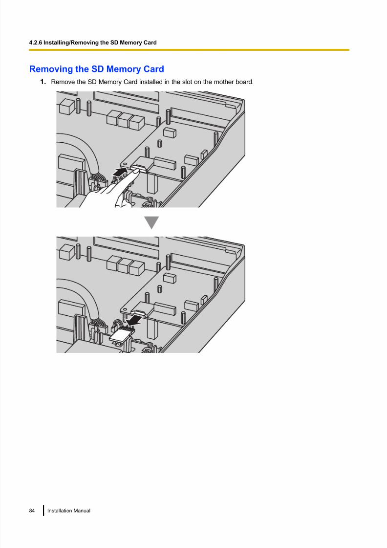
8/18/2019 NS500 Installation Manual
http://slidepdf.com/reader/full/ns500-installation-manual 84/300
Removing the SD Memory Card
1. Remove the SD Memory Card installed in the slot on the mother board.
84 Installation Manual
4.2.6 Installing/Removing the SD Memory Card

8/18/2019 NS500 Installation Manual
http://slidepdf.com/reader/full/ns500-installation-manual 85/300
4.2.7 Types of Connectors
Connector Type Pin Number Used for
RJ45
(Twisted pair cable)
81
• Mother board (KX-NS500)
– LAN Port
– Trunk I/F Port
– DPT I/F Port
– SLT I/F Port
• Mother Board (KX-NS520)
– PFT I/F Port
– SLT I/F Port
• EXP-M port
• EXP-S port
• LCOT6 (KX-NS5180)
• PRI30/E1 (KX-NS5290CE)
• DPH2 (KX-NS5162)
• DHLC4 (KX-NS5170)
• DLC8 (KX-NS5171)
• DLC16 (KX-NS5172)
• MCSLC8 (KX-NS5173)
• MCSLC16 (KX-NS5174)
Note
• Pin assignments for RJ45 connectors differ depending on the card. Refer to the "Pin Assignments"
section of each card in "Section 4 Installation".
KX-TDA0158 connecting to KX-NS500
CS1 (RJ45)
PIN No.Signal Name
D1C
D2C
D1B
D1A
Master D2A
D2B
D1A
D2A
D1B
D2B
D1D
D2D
1
2
3
4
5
6
7
8
DHLC4/DLC8/DLC16 card (RJ45)
Signal Name Port No.PIN No.
1
1
2
3
4
5
6
7
8
Note
• The no. 4 and 5 pins (Master) of the CS must be connected to a pair of pins on the DHLC/DLC card.
• When connecting multiple KX-TDA0158 CSs to a DHLC/DLC card, make sure that the no. 4 and 5 pins
(Master) of adjacent CSs are at least 1 pair of pins away on the card.
• CS connections must be made within the same DHLC/DLC card.
Installation Manual 85
4.2.7 Types of Connectors

8/18/2019 NS500 Installation Manual
http://slidepdf.com/reader/full/ns500-installation-manual 86/300
• When a wrong connection is made, satisfactory performance of the CS cannot be guaranteed.
Check the connection of CS and the PBX using the Web Maintenance Console. For information about
how to view CS information using the Web Maintenance Console, refer to "4.1.2 Status—Equipment
Status—CS Information" in the PC Programming Manual.
• KX-TDA0158 CS cannot be connected to DLC2 (installed by default).
86 Installation Manual
4.2.7 Types of Connectors

8/18/2019 NS500 Installation Manual
http://slidepdf.com/reader/full/ns500-installation-manual 87/300
4.2.8 Attaching a Ferrite Core
A ferrite core must be attached when an RJ45 connector is connected to the EXP-M card or EXP-S card.
For the EXP-M/EXP-S Cards
Wrap the cable once around the ferrite core, then close the case of the ferrite core. Attach the ferrite core
5 cm away from the connector. The ferrite core is included with the Expansion Unit.
5 cm
Installation Manual 87
4.2.8 Attaching a Ferrite Core

8/18/2019 NS500 Installation Manual
http://slidepdf.com/reader/full/ns500-installation-manual 88/300
4.2.9 19-inch Rack Mounting
WARNING
• Be careful not to drop any components. Dropping components may damage them or cause aninjury.
• When mounting the PBX on a 19-inch rack, only use the 19-inch rack mounting equipment
(attachment bracket, screws) included with the PBX.
CAUTION
• When the PBX is mounted on a 19-inch rack, make sure that the installation of the unit does not cause
the temperature of the rack to exceed its limit.
• When the PBX is mounted on a 19-inch rack, do not block the openings of the PBX. Allow space of at
least 10 cm around the PBX’s fan.
• If the PBX is not installed properly using the securing correct methods, the PBX may fall causing serious
damage.
• When this product is no longer in use, make sure to detach it from the rack.
1. Fix the attachment brackets to the left and right sides of the PBX with 3 screws on each side.
(Recommended torque: 0.8 N·m [8.2 kgf·cm] to 1.0 N·m [10.2 kgf·cm])® 1
2. Place the PBX in the 19-inch rack and fix both attachment brackets to the rack with the rack’s proprietary
mounting equipment.® 2
1
2
Screw
Attachment Bracket
88 Installation Manual
4.2.9 19-inch Rack Mounting

8/18/2019 NS500 Installation Manual
http://slidepdf.com/reader/full/ns500-installation-manual 89/300
4.2.10 Wall Mounting
The PBX can be mounted on a concrete wall using the optional wall mounting kit.
WARNING
• Make sure that the wall that the unit will be attached to is strong enough to support
approximately 4 times the weight of the unit. If not, it is necessary for the wall to be reinforced.
• Only use the wall-mounting equipment (screws and washers) included with the PBX.
• Be careful not to drop any components. Dropping components may damage them or cause an
injury.
• Proper earthing (connection to earth) is very important to reduce the risk to the user of
electrocution or to protect the PBX from the bad effects of external noise in the case of a
lightning strike. (See "4.2.4 Frame Earth Connection".)
CAUTION
• Make sure to install all necessary optional service cards in the PBX before performing the wall mountingprocedure. If it is necessary to install or remove a card, make sure to detach the PBX from the wall
before installing or removing the card.
• Do not block the openings of the PBX. Allow space of at least 20 cm above and 10 cm at the sides of
the PBX.
• Make sure that the surface behind the PBX is flat and free of obstacles, so that the openings on the
back of the PBX will not be blocked.
• If the PBX is not installed properly using the securing correct methods, the PBX may fall causing serious
damage.
• When driving the screws into the wall, be careful to avoid touching any metal laths, wire laths or plates
in the wall.
• When this product is no longer in use, make sure to detach it from the wall.
Note
For details about dimensions and weight of the PBX, see "2.3.1 General Description".
Necessary Items
Included in the PBX
Screw A (For use in concrete) 3
Washer 3
Wall Mounting ProceduresCAUTION
Drive mounting screws into the wall. Be careful to avoid touching any metals laths, wire laths or metal
plates in the wall.
Installation Manual 89
4.2.10 Wall Mounting

8/18/2019 NS500 Installation Manual
http://slidepdf.com/reader/full/ns500-installation-manual 90/300
Mounting on a Wooden Wall
The included screws may be used when mounting the main unit on a wooden wall.
1. Measure the actual space as indicated below to mark the 3 screw positions on the wall.
290 mm
100 mm
200 mm
2. Install the screws and washers (included) to the wall.
Washer
Drive the screwto this position.
Note
• As indicated above, do not tighten the screw fully.
• The pull-out strength of the installation area must be at least 294 N (30 kgf) per screw.• Do not block the operations of the cabinet. Allow space of at least 20 cm above and 10 cm at the
sides of the cabinet.
• Make sure that screw heads are the same distance from the wall.
• Install the screw perpendicular to the wall.
3. Hook the main unit on the screw heads.
90 Installation Manual
4.2.10 Wall Mounting

8/18/2019 NS500 Installation Manual
http://slidepdf.com/reader/full/ns500-installation-manual 91/300
Mounting on a Concrete
The included screws may be used when mounting the main unit on a concrete wall. User-supplied anchor
plugs are also necessary.
1. Measure the actual space as indicated below to mark the 3 screw positions on the wall.
290 mm
100 mm
200 mm
2. Drill holes in the wall as marked and fit the anchor plugs (not included) into the holes.
Hammer
29 mm
Anchor Plug
6.4 mm
3. Fit the washers on the screws, and drive the screws into the anchor plugs.
Drive the screwto this point.
Note
• As indicated above, do not tighten the screw fully.
• The pull-out strength of the installation area must be at least 294 N (30 kgf) per screw.
• Do not block the operations of the cabinet. Allow space of at least 20 cm above and 10 cm at thesides of the cabinet.
• Make sure that screw heads are the same distance from the wall.
• Install the screw perpendicular to the wall.
Installation Manual 91
4.2.10 Wall Mounting
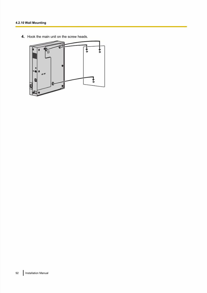
8/18/2019 NS500 Installation Manual
http://slidepdf.com/reader/full/ns500-installation-manual 92/300
4. Hook the main unit on the screw heads.
92 Installation Manual
4.2.10 Wall Mounting

8/18/2019 NS500 Installation Manual
http://slidepdf.com/reader/full/ns500-installation-manual 93/300
4.2.11 Surge Protector Installation
CAUTION
Performing surge protection is essential. Make sure to follow the instructions in this section.
Overview
A massive electrical surge can be caused if lightning strikes a telephone cable 10 m above ground, or if a
telephone line comes into contact with a power line. A surge protector is a device that is connected to a trunk
to prevent potentially dangerous electrical surges from entering the building via the trunk and damaging the
PBX and connected equipment.
To protect the system from electrical surges, we strongly recommend connecting the system to a surge
protector that meets the following specifications:
– Surge arrestor type: 3-electrode arrestor
– DC spark-over voltage: 230 V – Maximum peak current: at least 10 kA
Additionally, proper earthing is very important for the protection of the system (refer to "4.2.4 Frame Earth
Connection").
Many countries/areas have regulations requiring surge protection. Be sure to comply with all applicable laws,
regulations, and guidelines.
Installation
Trunk TrunkTrunk
Earth
SurgeProtector
Extn.
Extn.
Extn.: Extension line
SLT
PBX
Frame
Earth
Terminal
Board
Installation Manual 93
4.2.11 Surge Protector Installation

8/18/2019 NS500 Installation Manual
http://slidepdf.com/reader/full/ns500-installation-manual 94/300
Outside Installation
Trunk
Extn.
Trunk
Surge Protector
Terminal
BoardSurge
Protector
PBX
(Main Building)
Extn.: Extension Line
Extn.
Extn.
Earth
Extn.
SLT
(Another Building)
SLT
If you install an extension outside of the building, the following precautions are recommended:
a. Install the extension wire underground.
b. Use a conduit to protect the wire.
Note
The surge protector for an extension is different from that for trunks.
Installation of an Earth Rod
Trunk
PBX
Earth Rod
(Underground)
Surge Protector
Earthing
Wire
94 Installation Manual
4.2.11 Surge Protector Installation

8/18/2019 NS500 Installation Manual
http://slidepdf.com/reader/full/ns500-installation-manual 95/300
1. Connect the earth rod to the surge protector using an earthing wire with a cross-sectional area of at least
1.3 mm2.
2. Bury the earth rod near the protector. The earthing wire should be as short as possible.
3. The earthing wire should run straight to the earth rod. Do not run the wire around other objects.4. Bury the earth rod at least 50 cm underground.
Note
• The above figures are recommendations only.
• The length of earth rod and the required depth depend on the composition of the soil.
Installation Manual 95
4.2.11 Surge Protector Installation

8/18/2019 NS500 Installation Manual
http://slidepdf.com/reader/full/ns500-installation-manual 96/300
4.2.12 Backup Battery Connection
The backup batteries and Back-up Battery Cable provide a backup power supply to allow full use of the PBX
in the event of a power failure. In case of power failure, the backup batteries automatically maintain the power
to the PBX without interruption.
User-supplied Items
• Backup Batteries: VRLA (Valve Regulated Lead Acid) 12 V DC ´ 3
• Back-up Battery Cable: KX-A228
WARNING
• There is a danger of explosion if backup batteries are incorrectly replaced. Replace only with
the same or equivalent type recommended by the battery manufacturer. Dispose of used
batteries according to the manufacturer’s instructions.
• Make sure that you do not short the backup batteries or cables.
CAUTION
• Make sure that the Back-up Battery Cable is securely fastened to both the backup batteries and the
PBX.
• Make sure that the polarities of the backup batteries and wiring are correct.
• Use the correct type of Back-up Battery Cable for the PSU.
Notice
Be sure to comply with applicable local regulations (e.g., laws, guidelines).
Note
• Turn on the battery switch on the PSU only after the installation of the PBX is finished and AC power
is available.
• The recommended maximum capacity is 28 Ah, to maintain effective battery charge.• Make sure that the type and capacity of the 3 backup batteries are identical.
• The Back-up Battery Cable should not be exposed to direct sunlight. Keep the Back-up Battery Cable
and the backup batteries away from heating appliances and fire. Place the backup batteries in a
ventilated place.
• For details about the backup batteries, refer to the manual for the batteries.
Backup Power Supply Duration
The length of time that backup batteries can power the PBX varies depending on the total load figure. For how
to calculate the load figure from the connected items, refer to "Load Figure Calculation".
Examples
Battery Capacity Backup Power Supply Duration*1
28 Ah 16 h
*1 The duration may vary depending on the conditions.
Connecting Backup Batteries
1. Turn off the battery switch on the back side.
96 Installation Manual
4.2.12 Backup Battery Connection

8/18/2019 NS500 Installation Manual
http://slidepdf.com/reader/full/ns500-installation-manual 97/300
2. Connect the Back-up Battery Cable to a set of 3 identical backup batteries.
Backup Batteries (VRLA 12 V DC x 3)
Red Black
Battery Connector
Fuse
Battery Switch
Back-up Battery Cable
Battery Connector Cover
Installation Manual 97
4.2.12 Backup Battery Connection

8/18/2019 NS500 Installation Manual
http://slidepdf.com/reader/full/ns500-installation-manual 98/300
4.3 The Mother Board and Expansion Cards
4.3.1 Mother Board
4.3.1.1 Mother Board - KX-NS500
Function
The mother board is the preinstalled processing board with activation keys for CA Basic-Express for unlimited
users, use of 4 IP-PT, and 2 Unified Messaging ports. The Virtual Cards (trunk/extension) can be installed in
Virtual Slots of the mother board and can be activated with the activation keys. Also, the mother board supports
LAN connection so that IP telephones (IP-PTs, IP softphones, SIP phones) and PCs can be connected on a
private IP network.
Mountable Cards
• One of the DSP S, DSP M or DSP L Card (refer to "4.3.3 DSP S Card (KX-NS5110), DSP M Card
(KX-NS5111), DSP L Card (KX-NS5112)")
• SD Memory Card (refer to "4.3.2 SD Memory XS Card (KX-NS5134), SD Memory S Card (KX-NS5135),
SD Memory M Card (KX-NS5136)")
• Remote Card refer to "4.3.10 RMT card in KX-NS500 (KX-TDA0196)")
EXP-M Card Slot
DSP Card Slot
System Mode Switch
LEDs
LAN Port
LEDSD Card Slot
To LAN
RMT Card Slot
Note
• Make sure to use the LAN port for LAN connection.
• The maximum length of the CAT 5/CAT 5e cables to be connected to the mother board is 100 m.
• For installing and removing the SD Memory Card, refer to "4.2.6 Installing/Removing the SD Memory
Card".
• For details about Virtual Slots, refer to "2.3.3 System Capacity".
98 Installation Manual
4.3.1 Mother Board

8/18/2019 NS500 Installation Manual
http://slidepdf.com/reader/full/ns500-installation-manual 99/300
• If the preinstalled activation keys on the mother board are not enough for the desired configuration,
you need to purchase activation key codes. For details about the activation keys, refer to
"3.1 Information about the Activation Keys".
•For details about connecting to a LAN, refer to "4.11 LAN Connection".
• For details about connecting peripherals, refer to "4.10 Connection of Peripherals".
• For details about System Mode Switch, refer to "4.13 Starting the KX-NS500".
WARNING
A lithium battery is used in the mother board. There is a risk of explosion if the battery is replaced
with the incorrect type. Dispose of used batteries according to the manufacturer’s instructions.
Pin Assignments
LAN Port (10BASE-T/100BASE-TX)
No. Signal Name Input (I)/Output (O) Function
81
1 TPO+ O Transmit data+
2 TPO- O Transmit data-
3 TPI+ I Receive data+
4-5 Reserved – –
6 TPI- I Receive data-
7-8 Reserved – –
LED Indications
Indication Colour Description
STATUS Green PBX status indication
• OFF: Power Off
• ON: Power On and running
• Flashing: Starting up/Logging in
Amber PBX status indication
• ON: Ready to shutdown
• Flashing: Shutting down
Red PBX status indication• ON: Alarm
The cause may be one of the following:
– Power was cut without performing the
shutdown procedure.
– No IP address(es) assigned for the DSP
card(s) by the DHCP server.
– Alarm for an optional service card.
• Flashing: Initialise failed
PBX MODE Off • Not Used
Installation Manual 99
4.3.1 Mother Board

8/18/2019 NS500 Installation Manual
http://slidepdf.com/reader/full/ns500-installation-manual 100/300
Indication Colour Description
10BASE-T/
100BASE-TX
LAN LINK Green Link status indication
• OFF: Off-line• ON: Linked normally
• Flashing: In communication
4.3.1.2 Mother Board - KX-NS520
Function
The mother board of expansion unit KX-NS520 is the pre-installed processing board with the EXP-S card, PFT
card, MCSLC16 card.
To EXP-M
LED
EXP-S CardPFT4 + MCSLC16 Card EXP-S Port
LED IndicationIndication Colour Description
STATUS Off Power Off
Green On On Line
Green flashing (60 times per minute) Starting Up
Green flashing (120 times per minute) EXP-S card Programme error
Red On On Line with Alarm
Red flashing (60 times per minute) OUS (Out of service)
100 Installation Manual
4.3.1 Mother Board
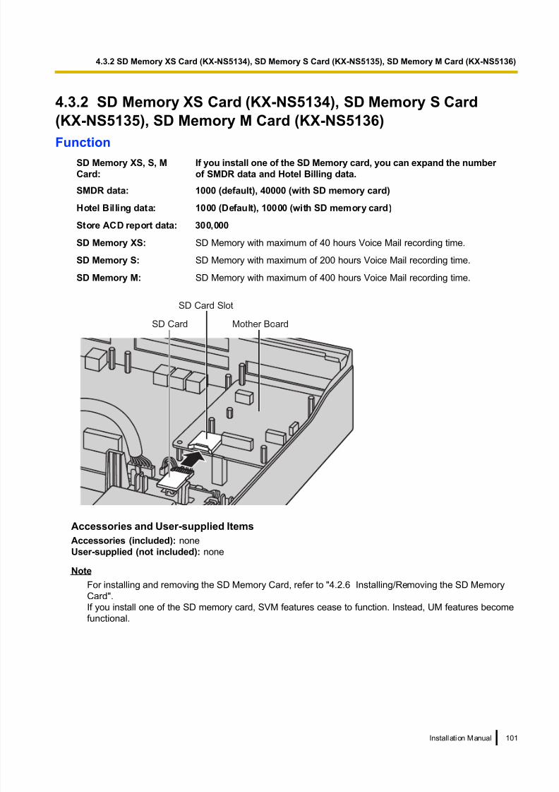
8/18/2019 NS500 Installation Manual
http://slidepdf.com/reader/full/ns500-installation-manual 101/300
4.3.2 SD Memory XS Card (KX-NS5134), SD Memory S Card
(KX-NS5135), SD Memory M Card (KX-NS5136)
Function
SD Memory XS, S, M
Card:
If you install one of the SD Memory card, you can expand the number
of SMDR data and Hotel Billing data.
SMDR data: 1000 (default), 40000 (with SD memory card)
Hotel Billing data: 1000 (Default), 10000 (with SD memory card)
Store ACD report data: 300,000
SD Memory XS: SD Memory with maximum of 40 hours Voice Mail recording time.
SD Memory S: SD Memory with maximum of 200 hours Voice Mail recording time.
SD Memory M: SD Memory with maximum of 400 hours Voice Mail recording time.
SD Card Mother Board
SD Card Slot
Accessories and User-supplied Items
Accessories (included): none
User-supplied (not included): none
Note
For installing and removing the SD Memory Card, refer to "4.2.6 Installing/Removing the SD Memory
Card".
If you install one of the SD memory card, SVM features cease to function. Instead, UM features become
functional.
Installation Manual 101
4.3.2 SD Memory XS Card (KX-NS5134), SD Memory S Card (KX-NS5135), SD Memory M Card (KX-NS5136)

8/18/2019 NS500 Installation Manual
http://slidepdf.com/reader/full/ns500-installation-manual 102/300
4.3.3 DSP S Card (KX-NS5110), DSP M Card (KX-NS5111), DSP L
Card (KX-NS5112)
Function A DSP card is a digital signal processor card with DSP resources that can be used for VoIP calls, conferences,
the Unified Messaging feature, and the DISA/OGM feature. The DSP cards are compliant with ITU-T G.
729A and G.711 codec methods.
To operate the IP trunk and/or IP extension, one of the DSP S, DSP M or DSP L card must be installed.
Screws
DSP Card
Accessories and User-supplied Items
Accessories (included): Screws ´ 2
User-supplied (not included): none
CAUTION
When installing or removing the optional service cards, do not put pressure on any parts of the mother
board. Doing so may result in damage to the PBX.
NoteThe DSP Resource Advisor can be used to calculate DSP resource usage easily. For details, refer to
"9.37.1.1 PBX Configuration—[1-5-1] Configuration—DSP Resource—Setting—DSP Resource Advisor"
in the PC Programming Manual.
DSP Resource Information
The number of resources provided by each type of DSP card is as follows:
DSP Card Type Number of Resources
DSP S 63
DSP M 127
102 Installation Manual
4.3.3 DSP S Card (KX-NS5110), DSP M Card (KX-NS5111), DSP L Card (KX-NS5112)

8/18/2019 NS500 Installation Manual
http://slidepdf.com/reader/full/ns500-installation-manual 103/300
DSP Card Type Number of Resources
DSP L 254
IP Address Information
Either 1 or 2 IP addresses must be assigned to each DSP card, depending on the type of DSP card. You can
assign IP addresses to the DSP cards during Easy Setup Wizard or through system programming.
For details about Easy Setup Wizard, refer to "5.4.1 Easy Setup Wizard".
For details about assigning IP addresses through System Programming, refer to "Changing IP Address
Settings".
DSP Card Type Number of IP Addresses
DSP S/DSP M 1
DSP L 2
Installation Manual 103
4.3.3 DSP S Card (KX-NS5110), DSP M Card (KX-NS5111), DSP L Card (KX-NS5112)
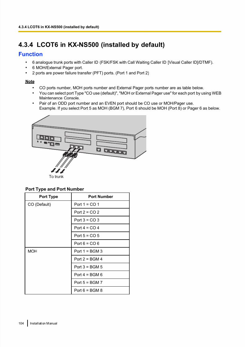
8/18/2019 NS500 Installation Manual
http://slidepdf.com/reader/full/ns500-installation-manual 104/300
4.3.4 LCOT6 in KX-NS500 (installed by default)
Function
• 6 analogue trunk ports with Caller ID (FSK/FSK with Call Waiting Caller ID [Visual Caller ID]/DTMF).
• 6 MOH/External Pager port.
• 2 ports are power failure transfer (PFT) ports. (Port 1 and Port 2)
Note
• CO ports number, MOH ports number and External Pager ports number are as table below.
• You can select port Type "CO use (default)", "MOH or External Pager use" for each port by using WEB
Maintenance Console.
• Pair of an ODD port number and an EVEN port should be CO use or MOH/Pager use.
Example. If you select Port 5 as MOH (BGM 7), Port 6 should be MOH (Port 8) or Pager 6 as below.
To trunk
Port Type and Port Number
Port Type Port Number
CO (Default) Port 1 = CO 1
Port 2 = CO 2
Port 3 = CO 3
Port 4 = CO 4
Port 5 = CO 5
Port 6 = CO 6
MOH Port 1 = BGM 3
Port 2 = BGM 4
Port 3 = BGM 5
Port 4 = BGM 6
Port 5 = BGM 7
Port 6 = BGM 8
104 Installation Manual
4.3.4 LCOT6 in KX-NS500 (installed by default)

8/18/2019 NS500 Installation Manual
http://slidepdf.com/reader/full/ns500-installation-manual 105/300
External Pager Port 1 = Pager 1
Port 2 = Pager 2
Port 3 = Pager 3
Port 4 = Pager 4
Port 5 = Pager 5
Port 6 = Pager 6
Port Type Setting by Web Maintenance Console
CO Use
CO Use
MOH or External Pager Use
Note
• For details about power failure transfer, refer to "4.12 Power Failure Connections".
• To confirm the trunk connection, refer to "Confirming the Trunk Connection" in "4.13 Starting the
KX-NS500".
Pin Assignment
For Trunk Use
No. Signal Name Function
81
1 TA Tip port 1
2 RA Ring port 1
3 Reserved –
4 Reserved –
5 Reserved –
6 Reserved –
7 TB Tip port 2
8 RB Ring port 2
Installation Manual 105
4.3.4 LCOT6 in KX-NS500 (installed by default)

8/18/2019 NS500 Installation Manual
http://slidepdf.com/reader/full/ns500-installation-manual 106/300
For MOH/Pager Use
No. Signal Name Function
81
1 M/P1 A Music/Pager port 1
2 M/P2 A Music/Pager port 1
3 Reserved –
4 Reserved –
5 Reserved –
6 Reserved –
7 M/P1 B Music/Pager port 2
8 M/P2 B Music/Pager port 2
106 Installation Manual
4.3.4 LCOT6 in KX-NS500 (installed by default)

8/18/2019 NS500 Installation Manual
http://slidepdf.com/reader/full/ns500-installation-manual 107/300
4.3.5 DLC2 in KX-NS500 (installed by default)
Function
• 2 digital extension port for DPT and PT-interface CSs.
To Extension
Pin Assignments
For DLC port
No. Signal Name Function
81
1 D1 A Data port 1 (Low)
2 D2 A Data port 1 (High)
3 D1 B Data port 2 (Low)
4 Reserved –
5 Reserved –
6 D2 B Data port 2 (High)
7 Reserved –
8 Reserved –
Installation Manual 107
4.3.5 DLC2 in KX-NS500 (installed by default)

8/18/2019 NS500 Installation Manual
http://slidepdf.com/reader/full/ns500-installation-manual 108/300
4.3.6 MCSLC16 in KX-NS500 (installed by default)
Function
• 16 extension ports for SLT with Caller ID (FSK), Message Waiting Lamp control, and 2 power failure transfer
(PFT) ports. Maximum power output of 90 V for Message Waiting Lamp control.
To Extension
Note
• For details about power failure transfer, refer to "4.12 Power Failure Connections".
Pin Assignments
For MCSLC16 port 1-2 and port 3-4No. Signal Name Function
81
1 TA Tip port 1
2 RA Ring port 1
3 Reserved –
4 Reserved –
5 Reserved –
6 Reserved –
7 TB Tip port 2
8 RB Ring port 2
108 Installation Manual
4.3.6 MCSLC16 in KX-NS500 (installed by default)

8/18/2019 NS500 Installation Manual
http://slidepdf.com/reader/full/ns500-installation-manual 109/300
For MCSLC16 port 5-8, port 9-12 and port 13-16
No. Signal Name Function
81
1 TA Tip port 1
2 RA Ring port 1
3 TB Tip port 2
4 TC Tip port 3
5 RC Ring port 3
6 RB Ring port 2
7 TD Tip port 4
8 RD Ring port 4
Installation Manual 109
4.3.6 MCSLC16 in KX-NS500 (installed by default)

8/18/2019 NS500 Installation Manual
http://slidepdf.com/reader/full/ns500-installation-manual 110/300
4.3.7 EXP-S in KX-NS520 (installed by default)
Function
• EXP-S is pre-installed in the SPR card (KX-NS520) to be used as Expansion Unit.
• By using this card, you can expand the Usage of Legacy Trunks and extensions.
To EXP-M Card
Notice
• When connecting the RJ45 connector, attach the ferrite core (included with the KX-NS520). Refer to
"4.2.8 Attaching a Ferrite Core".
Pin Assignments
For EXP-S port
No. Signal Name Function
81
1 UHW+ Receive data+
2 UHW- Receive data-
3 REFCLK+ Reference CLK+
4 FHCLK+ Frame and System CLK+
5 FHCLK- Frame and System CLK-
6 REFCLK- Reference CLK-
7 DHW+ Transmit data+
8 DHW- Transmit data-
110 Installation Manual
4.3.7 EXP-S in KX-NS520 (installed by default)

8/18/2019 NS500 Installation Manual
http://slidepdf.com/reader/full/ns500-installation-manual 111/300
4.3.8 PFT in KX-NS520 (installed by default)
Function
When the power supply to the Expansion Unit fails, power failure transfer (PFT) will switch from the currentconnection to the Power Failure Connection. Refer to "5.6.2 Power Failure Transfer" in the Feature Guide for
further information.
The detail information about this card, refer to "4.12 Power Failure Connections".
Pin Assignments
For PFT port
No. Signal Name Function
81
1 TA Tip port 1
2 RA Ring port 1
3 Reserved –
4 Reserved –
5 Reserved –
6 Reserved –
7 TB Tip port 2
8 RB Ring port 2
Installation Manual 111
4.3.8 PFT in KX-NS520 (installed by default)

8/18/2019 NS500 Installation Manual
http://slidepdf.com/reader/full/ns500-installation-manual 112/300
To SLT1, SL2
To SLT3, SL4
Optional card KX-NS5180
No. Signal Name
81
1 TA
2 RA
3
4 Reserved
5 Reserved CO1 Tip
6 Reserved
7 TB
8 RB
PFT1-2
Reserved
No. Signal Name
81
1 TA
2 RA
3
4 Reserved
5 Reserved
6 Reserved
7 TB
8 RB
Reserved
CO1 Ring
CO2 Tip
CO2 Ring
Optional card KX-NS5180
No. Signal Name
81
1 TC
2 RC
3
4 Reserved
5 Reserved CO3 Tip
6 Reserved
7 TD
8 RD
PFT3-4
Reserved
No. Signal Name
81
1 TC
2 RC
3
4 Reserved
5 Reserved
6 Reserved
7 TD
8 RD
Reserved
CO3 Ring
CO4 Tip
CO4 Ring
112 Installation Manual
4.3.8 PFT in KX-NS520 (installed by default)

8/18/2019 NS500 Installation Manual
http://slidepdf.com/reader/full/ns500-installation-manual 113/300
4.3.9 MCSLC16 in KX-NS520 (installed by default)
Function
• 16 extension ports for SLT with Caller ID (FSK), Message Waiting Lamp control, and 4 power failure transfer
(PFT) ports. Maximum power output of 90 V for Message Waiting Lamp control.
To Extension
Note
• For details about power failure transfer, refer to "4.12 Power Failure Connections".
Pin Assignments
For MCSLC port 1-2 and Port 3-4
No. Signal Name Function
81
1 TA Tip port 1
2 RA Ring port 1
3 Reserved –
4 Reserved –
5 Reserved –
6 Reserved –
7 TB Tip port 2
8 RB Ring port 2
Installation Manual 113
4.3.9 MCSLC16 in KX-NS520 (installed by default)

8/18/2019 NS500 Installation Manual
http://slidepdf.com/reader/full/ns500-installation-manual 114/300
For MCSLC port 5-8, port 9-12 and port 13-16
No. Signal Name Function
81
1 TA Tip port 1
2 RA Ring port 1
3 TB Tip port 2
4 TC Tip port 3
5 RC Ring port 3
6 RB Ring port 2
7 TD Tip port 4
8 RD Ring port 4
114 Installation Manual
4.3.9 MCSLC16 in KX-NS520 (installed by default)

8/18/2019 NS500 Installation Manual
http://slidepdf.com/reader/full/ns500-installation-manual 115/300
4.3.10 RMT card in KX-NS500 (KX-TDA0196)
Function
Analogue modem card for remote communication with the PBX. IUT-T V.90 support. To be mounted on theKX-NS500 MPR card.
RMT Card Slot
RMT Card
ScrewScrew
Accessories and User-supplied Items
Accessories (included): Screw x 2
Installation Manual 115
4.3.10 RMT card in KX-NS500 (KX-TDA0196)
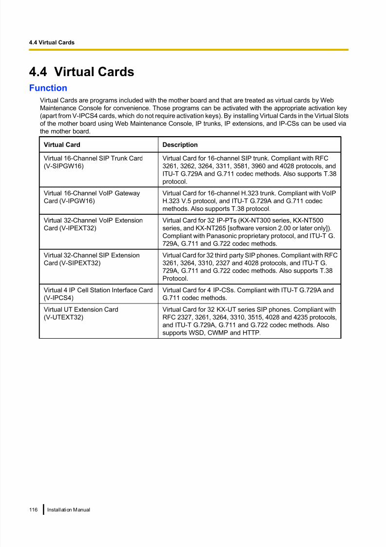
8/18/2019 NS500 Installation Manual
http://slidepdf.com/reader/full/ns500-installation-manual 116/300
4.4 Virtual CardsFunction
Virtual Cards are programs included with the mother board and that are treated as virtual cards by Web
Maintenance Console for convenience. Those programs can be activated with the appropriate activation key
(apart from V-IPCS4 cards, which do not require activation keys). By installing Virtual Cards in the Virtual Slots
of the mother board using Web Maintenance Console, IP trunks, IP extensions, and IP-CSs can be used via
the mother board.
Virtual Card Description
Virtual 16-Channel SIP Trunk Card
(V-SIPGW16)
Virtual Card for 16-channel SIP trunk. Compliant with RFC
3261, 3262, 3264, 3311, 3581, 3960 and 4028 protocols, and
ITU-T G.729A and G.711 codec methods. Also supports T.38
protocol.
Virtual 16-Channel VoIP GatewayCard (V-IPGW16)
Virtual Card for 16-channel H.323 trunk. Compliant with VoIPH.323 V.5 protocol, and ITU-T G.729A and G.711 codec
methods. Also supports T.38 protocol.
Virtual 32-Channel VoIP Extension
Card (V-IPEXT32)
Virtual Card for 32 IP-PTs (KX-NT300 series, KX-NT500
series, and KX-NT265 [software version 2.00 or later only]).
Compliant with Panasonic proprietary protocol, and ITU-T G.
729A, G.711 and G.722 codec methods.
Virtual 32-Channel SIP Extension
Card (V-SIPEXT32)
Virtual Card for 32 third party SIP phones. Compliant with RFC
3261, 3264, 3310, 2327 and 4028 protocols, and ITU-T G.
729A, G.711 and G.722 codec methods. Also supports T.38
Protocol.
Virtual 4 IP Cell Station Interface Card
(V-IPCS4)
Virtual Card for 4 IP-CSs. Compliant with ITU-T G.729A and
G.711 codec methods.
Virtual UT Extension Card
(V-UTEXT32)
Virtual Card for 32 KX-UT series SIP phones. Compliant with
RFC 2327, 3261, 3264, 3310, 3515, 4028 and 4235 protocols,
and ITU-T G.729A, G.711 and G.722 codec methods. Also
supports WSD, CWMP and HTTP.
116 Installation Manual
4.4 Virtual Cards

8/18/2019 NS500 Installation Manual
http://slidepdf.com/reader/full/ns500-installation-manual 117/300
Example: Virtual Cards in the Virtual Slots of the PBX
Virtual Slots
V-SIPGW16
V-IPGW16
V-IPEXT32
V-UTEXT32
V-SIPEXT32
V-IPCS4
Mother Board
Installation Manual 117
4.4 Virtual Cards

8/18/2019 NS500 Installation Manual
http://slidepdf.com/reader/full/ns500-installation-manual 118/300
4.5 Physical Trunk and Extension Cards
4.5.1 LCOT6 Card (KX-NS5180)
Function
A combination card including:
• 6 analogue trunk ports with Caller ID (FSK/FSK with Call Waiting Caller ID [Visual Caller ID]/DTMF).
To trunk
RJ45
Accessories and User-supplied Items
Accessories (included): Spacer ´ 3, slot cover ´ 1
User-supplied (not included): RJ45 connector, Copper wire
Note
• For details about power failure transfer, refer to "4.12 Power Failure Connections".
• To confirm the trunk connection, refer to "Confirming the Trunk Connection" in "4.13 Starting the
KX-NS500".
Pin Assignments
For Trunk Use
No. Signal Name Function
81
1 TA Tip port 1
2 RA Ring port 1
3 Reserved –
4 Reserved –
5 Reserved –
6 Reserved –
7 TB Tip port 2
8 RB Ring port 2
118 Installation Manual
4.5.1 LCOT6 Card (KX-NS5180)

8/18/2019 NS500 Installation Manual
http://slidepdf.com/reader/full/ns500-installation-manual 119/300
4.5.2 PRI30/E1 Card (KX-NS5290CE)
Function
A combination card including:
• 1 ISDN Primary Rate Interface port (30B channels).
EURO-ISDN/ETSI compliant.
1 E1 port (30B channels).
ITU-T standard compliant.
To NT1/ Extension LED
RJ45
Accessories and User-supplied Items
Accessories (included): Spacer ´ 3, slot cover ´ 1
User-supplied (not included): RJ45 connector, Twisted pair cable
CAUTION• When connecting this optional service card to the trunk, connect through an NT1; do not connect to
the U interface of the trunk directly.
• PRI ports are SELV ports and should only be connected to SELV services.
Notice
• The cable to connect to the ISDN Primary Rate Interface port of the PRI30/E1 card should be CAT 5
(Category 5) or higher.
Note
• You can select PRI30 use or E1 use by Web Maintenance Console.
– For switching from PRI30 use to E1 use:
Delete the PRI30 card first and select the E1 card in the "PBX Configuration ® Configuration®Slot" screen of the Web Maintenance Console. To restart the PBX, click Maintenance ® System
Control ® System Reset.
– For switching from E1 use to PRI30 use:
Delete the E1 card first and select the PRI30 card in the "PBX Configuration® Configuration®
Slot" screen of the Web Maintenance Console. To restart the PBX, click Maintenance ® System
Control ® System Reset.
• In some countries/areas, this optional service card must not be connected to the Public Switched
Telephone Network.
• To confirm the trunk connection, refer to "Confirming the Trunk Connection" in "4.13 Starting the
KX-NS500".
Installation Manual 119
4.5.2 PRI30/E1 Card (KX-NS5290CE)

8/18/2019 NS500 Installation Manual
http://slidepdf.com/reader/full/ns500-installation-manual 120/300
Pin Assignments
No. Signal Name Level [V] Function
81
1 RX+ (+) Receive data (+)
2 RX- (-) Receive data (-)
3 Reserved – –
4 TX- (-) Transmit data (-)
5 TX+ (+) Transmit data (+)
6-8 Reserved – –
For Trunk Use
Telephone Company
PRI/E1 Line
Behind PBX
No. Signal Name Level [V] Function
81
1 RX+ (+) Receive data (+)
2 RX-
RX(-)
RX(+)
(-) Receive data (-)
3 – –
4 TX- (-) Transmit data (-)
5 TX+
TX(+)
TX(-)
(+) Transmit data (+)
6-8 Reserved – –
For Extension/QSIG Use
Reserved
No. Signal Name Level [V] Function
81
1 RX+ (+) Receive data (+)
2 RX- (-) Receive data (-)
3 – –
4 TX- (-) Transmit data (-)
5 TX+ (+) Transmit data (+)
6-8 Reserved – –
Reserved
1
2
3
4
5
6-8
RX(+)
RX(-)
TX(+)
TX(-)
1
2
3
4
5
6-8
Example:
Example:
LED Indications
When you select PRI use
Indication Colour Description
STATUS Green Off : All Ports OUS or Fault
On: INS (In Service)
Flashing (60 times per minute): Normal (a port is in use)
120 Installation Manual
4.5.2 PRI30/E1 Card (KX-NS5290CE)

8/18/2019 NS500 Installation Manual
http://slidepdf.com/reader/full/ns500-installation-manual 121/300
When you select E1 use
Indication Colour Description
STATUS Green Off : All Ports OUS or FaultOn: At lease one port is In Service
Flashing (60 times per minute): Normal (a port is in use)
Maximum Cabling Distance of Extension Connection
The maximum length of the extension cable that connects the PRI port is shown below:
CAT 5: Under 200 m
Installation Manual 121
4.5.2 PRI30/E1 Card (KX-NS5290CE)

8/18/2019 NS500 Installation Manual
http://slidepdf.com/reader/full/ns500-installation-manual 122/300
4.5.3 DHLC4 Card (KX-NS5170)
Function
4-port digital hybrid extension card for DPTs, APTs, SLTs, DSS consoles, and PT-interface CSs.
To Extension
RJ45
Accessories and User-supplied Items
Accessories (included): Spacer ´ 3, slot cover ´ 1
User-supplied (not included): RJ45 connector, Twisted pair cable
Pin Assignments
No. Signal Name Function
81
1 D1A Data port 1 (low)
2 D2A Data port 1 (High)
3 D1B Data port 2 (low)
4 TB Tip port 2
5 RB Ring port 2
6 D2B Data port 2 (High)
7 TA Tip port 1
8 RA Ring port 1
122 Installation Manual
4.5.3 DHLC4 Card (KX-NS5170)

8/18/2019 NS500 Installation Manual
http://slidepdf.com/reader/full/ns500-installation-manual 123/300
4.5.4 DLC8 Card (KX-NS5171)
Function
8-port digital extension card for DPTs and PT-interface CSs.
To Extension
RJ45
Accessories and User-supplied Items
Accessories (included): Spacer ´ 4, slot cover ´ 1
User-supplied (not included): RJ45 connector, Twisted pair cable
Pin Assignments
No. Signal Name Function
81
1 D1A Data port 1 (Low)
2 D2A Data port 1 (High)
3 D1B Data port 2 (Low)
4 D1C Data port 3 (Low)
5 D2C Data port 3 (High)
6 D2B Data port 2 (High)
7 D1D Data port 4 (Low)
8 D2D Data port 4 (High)
Installation Manual 123
4.5.4 DLC8 Card (KX-NS5171)

8/18/2019 NS500 Installation Manual
http://slidepdf.com/reader/full/ns500-installation-manual 124/300
4.5.5 DLC16 Card (KX-NS5172)
Function
16-port digital extension card for DPTs and PT-interface CSs.
To Extension
RJ45
Accessories and User-supplied Items
Accessories (included): Spacer ´ 4, slot cover ´ 1
User-supplied (not included): RJ45 connector, Twisted pair cable
Pin Assignments
No. Signal Name Function
81
1 D1A Data port 1 (Low)
2 D2A Data port 1 (High)
3 D1B Data port 2 (Low)
4 D1C Data port 3 (Low)
5 D2C Data port 3 (High)
6 D2B Data port 2 (High)
7 D1D Data port 4 (Low)
8 D2D Data port 4 (High)
124 Installation Manual
4.5.5 DLC16 Card (KX-NS5172)

8/18/2019 NS500 Installation Manual
http://slidepdf.com/reader/full/ns500-installation-manual 125/300
4.5.6 MCSLC8 Card (KX-NS5173)
Function
8-port extension card for SLTs with Caller ID (FSK), Message Waiting Lamp control.
To Extension
RJ45
Accessories and User-supplied Items
Accessories (included): Spacer ´ 3, slot cover ´ 1
User-supplied (not included): RJ45 connector, Copper wire
Pin Assignments
No. Signal Name Function
81
1 TA Tip port 1
2 RA Ring port 1
3 TB Tip port 2
4 TC Tip port 3
5 RC Ring port 3
6 RB Ring port 2
7 TD Tip port 4
8 RD Ring port 4
Installation Manual 125
4.5.6 MCSLC8 Card (KX-NS5173)

8/18/2019 NS500 Installation Manual
http://slidepdf.com/reader/full/ns500-installation-manual 126/300
4.5.7 MCSLC16 Card (KX-NS5174)
Function
16-port extension card for SLTs with Caller ID (FSK), Message Waiting Lamp control.
To Extension
RJ45
Accessories and User-supplied Items
Accessories (included): Spacer ´ 3, slot cover ´ 1
User-supplied (not included): RJ45 connector, Copper wire
Pin Assignments
No. Signal Name Function
81
1 TA Tip port 1
2 RA Ring port 1
3 TB Tip port 2
4 TC Tip port 3
5 RC Ring port 3
6 RB Ring port 2
7 TD Tip port 4
8 RD Ring port 4
126 Installation Manual
4.5.7 MCSLC16 Card (KX-NS5174)

8/18/2019 NS500 Installation Manual
http://slidepdf.com/reader/full/ns500-installation-manual 127/300
4.6 Expansion Card
4.6.1 EXP-M Card (KX-NS5130)
Function
A stacking card to be installed in a KX-NS500. Up to 3 expansion units can be connected.
To EXP-S Card
Accessories and User-supplied Items
Accessories (included): Screws ´ 3, slot cover ´ 1
User-supplied (not included): RJ45 connector, Twisted pair cable (maximum 3 m)
CAUTION
When installing or removing this card, the power switch must be turned off.
Notice
• When connecting the RJ45 connector, attach the ferrite core (included with the KX-NS520). Refer to"4.2.8 Attaching a Ferrite Core".
Note
Status LED on KX-NS520 indicates the connection status between EXP-M in KX-NS500 and EXP-S in
KX-NS520.
For more detail, refer to KX-NS520 - LED Indication in "4.3.1 Mother Board".
Pin Assignments
No. Signal Name Function
81
1 UHW+ Receive data +
2 UHW- Receive data -
3 REFCLK+ Reference CLK +
4 FHCLK+ Frame and System CLK +
5 FHCLK- Frame and System CLK -
6 REFCLK- Reference CLK -
7 DHW+ Transmit data +
8 DHW- Transmit data -
Installation Manual 127
4.6.1 EXP-M Card (KX-NS5130)

8/18/2019 NS500 Installation Manual
http://slidepdf.com/reader/full/ns500-installation-manual 128/300
Maximum Cabling Length of Extension Connection
The maximum length of the extension cable that connects the Main Unit to the Expansion Unit is shown below:
Under 3 m
128 Installation Manual
4.6.1 EXP-M Card (KX-NS5130)
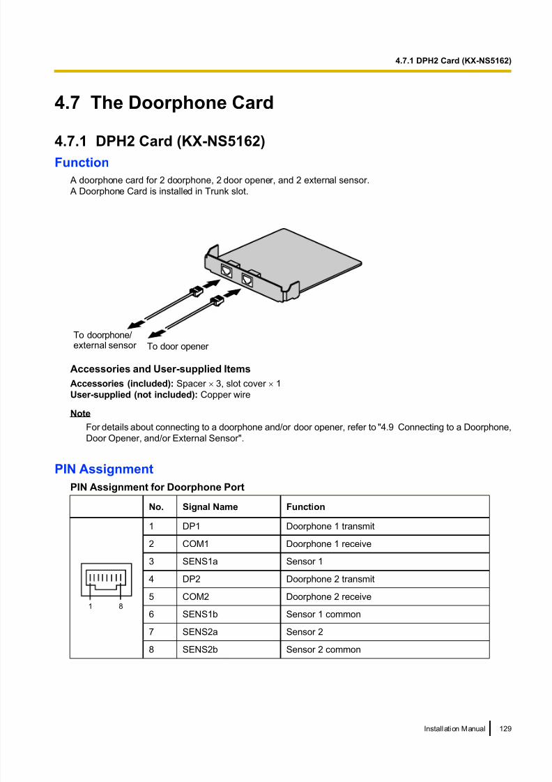
8/18/2019 NS500 Installation Manual
http://slidepdf.com/reader/full/ns500-installation-manual 129/300
4.7 The Doorphone Card
4.7.1 DPH2 Card (KX-NS5162)
Function
A doorphone card for 2 doorphone, 2 door opener, and 2 external sensor.
A Doorphone Card is installed in Trunk slot.
To doorphone/external sensor To door opener
Accessories and User-supplied Items
Accessories (included): Spacer ´ 3, slot cover ´ 1
User-supplied (not included): Copper wire
Note
For details about connecting to a doorphone and/or door opener, refer to "4.9 Connecting to a Doorphone,
Door Opener, and/or External Sensor".
PIN Assignment
PIN Assignment for Doorphone Port
No. Signal Name Function
81
1 DP1 Doorphone 1 transmit
2 COM1 Doorphone 1 receive3 SENS1a Sensor 1
4 DP2 Doorphone 2 transmit
5 COM2 Doorphone 2 receive
6 SENS1b Sensor 1 common
7 SENS2a Sensor 2
8 SENS2b Sensor 2 common
Installation Manual 129
4.7.1 DPH2 Card (KX-NS5162)

8/18/2019 NS500 Installation Manual
http://slidepdf.com/reader/full/ns500-installation-manual 130/300
PIN Assignment for Door opener Port
No. Signal Name Function
81
1 OP1a Door opener 1 (Relay 1)
2 OP1b Door opener 1 com (Relay 1 com)
3 Reserved -
4 Reserved -
5 Reserved -
6 Reserved -
7 OP2a Door opener 2 (Relay 2)
8 OP2b Door opener 2 com (Relay 2 com)
External Sensor
Power to the external sensor is provided from the DPH2 card and must be grounded through the DPH2 card
as indicated in the diagram below. A pair of "sensor" and "common" lines are connected to the DPH2 card for
each external sensor. The PBX detects input from the sensor when the signal is under 100 W.
Connection Diagram
External Sensor
sensor
common
I/O
DOORPHONE
PBX
+3.3V+3.3V
10K
33
334.7K
4.7K
Door Opener
Current Limit: 24 V DC/30 V AC, 1 A maximum
130 Installation Manual
4.7.1 DPH2 Card (KX-NS5162)

8/18/2019 NS500 Installation Manual
http://slidepdf.com/reader/full/ns500-installation-manual 131/300
4.8 Connection of Extensions
4.8.1 Maximum Cabling Distances of the Extension Wiring(Twisted Cable)
Cable Maximum Distance
ø 0.4 mm: 222 m
ø 0.5 mm: 347 m
ø 0.6 mm: 500 m
CAT 5: 347 m
Cable Maximum Distance
ø 0.4 mm: 140 m
ø 0.5 mm: 229 m
ø 0.6 mm: 360 m
CAT 5: 229 m
Cable Maximum Distance
ø 0.4 mm: 698 m
ø 0.5 mm: 1128 m
ø 0.6 mm: 1798 m
CAT 5: 1128 m
SLT
APT and DSS Console
PT-interface CS
DPTCable Maximum Distance
ø 0.4 mm: 500 m
ø 0.5 mm: 720 m
ø 0.6 mm: 830 m
CAT 5: 720 m
Notice
The maximum cabling distance may vary depending on the conditions.
PT-interfaceCS
DPT APTDSS
ConsoleSLT
DHLC4 Card ü ü ü ü ü
MCSLC8, MCSLC16
cards ü
DLC2, DLC8, DLC16
cards ü ü
"ü" indicates that the extension card supports the terminal.
Installation Manual 131
4.8.1 Maximum Cabling Distances of the Extension Wiring (Twisted Cable)

8/18/2019 NS500 Installation Manual
http://slidepdf.com/reader/full/ns500-installation-manual 132/300
4.8.2 Parallel Connection of the Extensions
Any SLT can be connected in parallel with an APT or a DPT as follows.
Note
In addition to an SLT, an answering machine, a fax machine or a modem (PC) can be connected in parallel
with an APT or a DPT.
With APT
For parallel connection, eXtra Device Port (XDP) mode must be disabled for that port through system
programming. Refer to "2.11.10 Parallelled Telephone" and "5.2.6 Extension Port Configuration" in the Feature
Guide for further information.
To DHLC4 card
4-conductor wiring cord
Connect pins "T", "R", "D1",
and "D2".
2-conductor wiring cord
Connect pins "T" and "R".
SLT APT
Modular T-Adaptor
With DPT
Parallel mode or eXtra Device Port (XDP) mode can be selected through system programming.
If XDP mode is enabled through system programming, parallel connection is not possible. Refer to "2.11.10
Parallelled Telephone" and "5.2.6 Extension Port Configuration" in the Feature Guide for further information.
Using a Modular T-Adaptor
To DHLC4 card
SLTDPT
Modular T-Adaptor
4-conductor wiring cord
Connect pins "D1" and
"D2".
2-conductor wiring cord
Connect pins "T" and "R".
132 Installation Manual
4.8.2 Parallel Connection of the Extensions

8/18/2019 NS500 Installation Manual
http://slidepdf.com/reader/full/ns500-installation-manual 133/300
Using an EXtra Device Port
Example: With KX-DT300 Series DPT*1
To DHLC4 card
DPT SLT
To DHLC4 card
To SLT
2-conductor wiring cord
Connect pins "T" and "R".4-conductor wiring cord
Connect pins "T", "R",
"D1" and "D2".
TO MAIN UNIT/ PABX
TO TEL
*1 Available for KX-DT300 Series DPT (except KX-DT321), KX-T7600 Series DPT (except KX-T7665) and KX-DT500 Series DPT
(except KX-DT521).
Installation Manual 133
4.8.2 Parallel Connection of the Extensions

8/18/2019 NS500 Installation Manual
http://slidepdf.com/reader/full/ns500-installation-manual 134/300
4.8.3 Digital EXtra Device Port (Digital XDP) Connection
A DPT can be connected to another DPT on the Digital XDP connection. In addition, if the DPT is connected
to a DHLC4 card, it can also have an SLT connected in Parallel mode or XDP mode.
Note
• Both DPTs must be KX-DT300/KX-DT500/KX-T7600 series DPTs (except KX-T7640). Note that the
KX-T7667 can only be connected as a slave DPT.
• Bluetooth® Modules or USB Modules must not be connected to DPTs in the Digital XDP connection.
• Parallel mode or XDP mode can be selected through system programming.
• If XDP mode is enabled through system programming, parallel connection is not possible. Refer to
"2.11.10 Parallelled Telephone" and "5.2.6 Extension Port Configuration" in the Feature Guide for
further information.
Example: With KX-DT300 Series DPT
Using a Modular T-Adaptor
Slave DPTMaster DPT
Cable Maximum Distance
ø 0.4 mm: 30 m
ø 0.5 mm: 50 m
ø 0.6 mm: 60 m
CAT 5: 50 m
Back View of DPTs
To DLC2/DLC8/DLC16 card
To DHLC4 card
(for connection of SLT)
TO MAIN UNIT
/ PABX
TO MAIN UNIT
/ PABX
TO TEL
To DLC2/DLC8/
DLC16 card
To DHLC4 card
(for connection of SLT)
4-conductor wiring cord
Connect pins "D1" and "D2".
Slave DPT
SLT
Master DPT
Modular
T-Adaptor
4-conductor wiring cord
Connect pins "D1" and"D2".
2-conductor wiring cord
Connect pins "T" and "R".
134 Installation Manual
4.8.3 Digital EXtra Device Port (Digital XDP) Connection

8/18/2019 NS500 Installation Manual
http://slidepdf.com/reader/full/ns500-installation-manual 135/300
Using an EXtra Device Port*1
SLTMaster DPT Slave DPT
4-conductor wiring cord
Connect pins "T", "R",
"D1" and "D2".
2-conductor wiring cord
Connect pins "T" and "R".
4-conductor wiring cord
Connect pins "T", "R",
"D1" and "D2".
To DLC2/DLC8/
DLC16 card
To DHLC4 card
(for connection of SLT)
To SLT
Slave DPTMaster DPT
Cable Maximum Distance
ø 0.4 mm: 30 m
ø 0.5 mm: 50 m
ø 0.6 mm: 60 m
CAT 5: 50 m
Back View of DPTs
To DLC2/DLC8/DLC16 card
To DHLC4 card
(for connection of SLT)
TO MAIN UNIT
/ PABX
TO MAIN UNIT
/ PABX
TO TEL
TO TEL
*1 Connecting with a SLT is not available for KX-DT321, KX-T7665 and KX-DT521.
Installation Manual 135
4.8.3 Digital EXtra Device Port (Digital XDP) Connection

8/18/2019 NS500 Installation Manual
http://slidepdf.com/reader/full/ns500-installation-manual 136/300
4.8.4 First Party Call Control CTI Connection
CTI connection between a PC and a KX-DT343/KX-DT346/KX-T7633/KX-T7636 DPT provides first party call
control. The CTI connection is made via a USB interface (version 2.0), and uses the TAPI 2.1 protocol. A USB
Module must be connected to the DPT.
Note
The operating system of the PC required for first party call control depends on your CTI application
software. For details, refer to the manual for your CTI application software.
KX-DT343/KX-DT346
USB Port USB Cable
USB Module
To PC
KX-T7633/KX-T7636
USB Cable
To PC
USB Port
USB Module
Note• The maximum length of the USB cable is 3 m.
136 Installation Manual
4.8.4 First Party Call Control CTI Connection

8/18/2019 NS500 Installation Manual
http://slidepdf.com/reader/full/ns500-installation-manual 137/300
4.9 Connecting to a Doorphone, Door Opener, and/
or External Sensor Main unit KX-NS500 and Expansion unit KX-NS520 support 2 doorphones, 2 door openers and 2 sensors.
Note
Doorphones, door openers, and external sensors are user-supplied.
Maximum Cabling Distance
Doorphone
Door Opener
Cable Maximum Distance
ø 0.42 mm: 70 m
ø 0.5 mm: 113 m
ø 0.6 mm: 180 m
CAT 5: 113 m
External Sensor
Installing the Doorphone (KX-T30865/KX-T7765)
Note
The illustrations shown in the installation procedure are based on the KX-T30865.
1. Loosen the screw to separate the doorphone into 2 halves.
P a n a s o
n i c
Screw
Installation Manual 137
4.9 Connecting to a Doorphone, Door Opener, and/or External Sensor
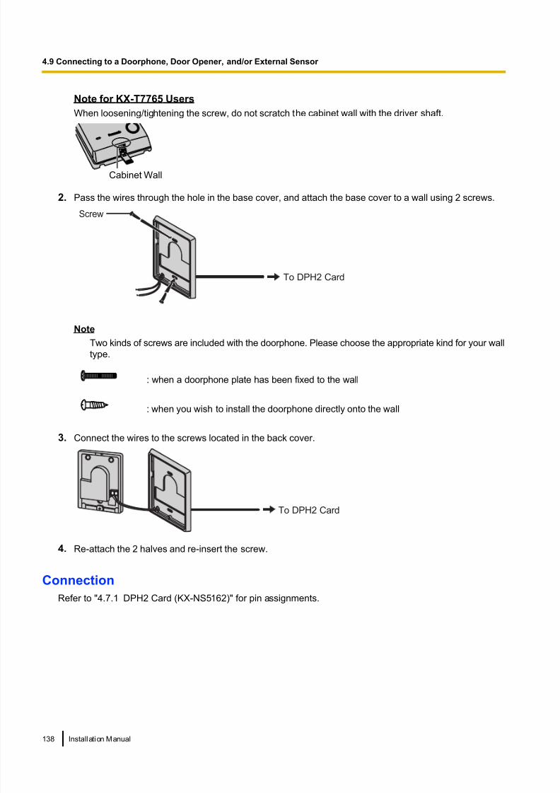
8/18/2019 NS500 Installation Manual
http://slidepdf.com/reader/full/ns500-installation-manual 138/300
Note for KX-T7765 Users
When loosening/tightening the screw, do not scratch the cabinet wall with the driver shaft.
Cabinet Wall
2. Pass the wires through the hole in the base cover, and attach the base cover to a wall using 2 screws.
Screw
To DPH2 Card
Note
Two kinds of screws are included with the doorphone. Please choose the appropriate kind for your wall
type.
: when a doorphone plate has been fixed to the wall
: when you wish to install the doorphone directly onto the wall
3. Connect the wires to the screws located in the back cover.
To DPH2 Card
4. Re-attach the 2 halves and re-insert the screw.
Connection
Refer to "4.7.1 DPH2 Card (KX-NS5162)" for pin assignments.
138 Installation Manual
4.9 Connecting to a Doorphone, Door Opener, and/or External Sensor

8/18/2019 NS500 Installation Manual
http://slidepdf.com/reader/full/ns500-installation-manual 139/300
4.10 Connection of Peripherals
Cable Maximum Distance
Maximum Distance
Cable Maximum Distance
PC
BGM
Music on Hold
Pager:
Amplifier/Speaker
ø 0.4 mm: 10 m
ø 0.5 mm: 10 m
ø 0.6 mm: 10 m
CAT 5/CAT 5e: 10 m
100 m
ø 0.4 mm: 10 m
ø 0.5 mm: 10 m
ø 0.6 mm: 10 m
CAT 5/CAT 5e: 10 m
LAN Port
USB Port
Maximum Distance
5 m
USB Memory
Device
Switching Hub
Maximum Distance
100 m
BGM/MOH
The PBX provides Background Music and Music on Hold. Up to 6 external music sources (e.g., user-supplied
radio) can be connected to the PBX.
CAUTION
The MOH port is an SELV port and should only be connected to an approved SELV device, via a Line
Isolation Unit with a Telecommunications Compliance Label.
Notice
• Wiring should be done carefully to prevent undue force being exerted on the plug. Otherwise, soundmay only be heard intermittently.
• When the PBX and external music source are not connected to the same earth, hum noise may be
induced into Background Music and Music on Hold.
Pager
A paging device (user-supplied) can be connected to the PBX.
CAUTION
The Pager port is an SELV port and should only be connected to an approved SELV device, via a Line
Isolation Unit with a Telecommunications Compliance Label.
Installation Manual 139
4.10 Connection of Peripherals

8/18/2019 NS500 Installation Manual
http://slidepdf.com/reader/full/ns500-installation-manual 140/300
USB Interface for USB Memory Device
The PBX is equipped with a USB 2.0 interface. This interface provides communication between the PBX and
user-supplied devices such as a USB memory device.
Using a USB memory device
A USB memory device can be used to backup and restore the system data of the PBX.
The PBX supports USB memory devices that meet the following specifications:
• File system: FAT
• Maximum capacity: 32 GB
• Maximum current: 500 mA
For details about backing up and restoring using a USB memory device, refer to "6.1 Tool—System Data
Backup" in the PC Programming Manual.
Note
Do not use a USB hub when connecting a USB memory device to the PBX.
140 Installation Manual
4.10 Connection of Peripherals

8/18/2019 NS500 Installation Manual
http://slidepdf.com/reader/full/ns500-installation-manual 141/300
4.11 LAN Connection
4.11.1 LAN Connection for the Main Unit
Connecting the Main Unit to the LAN
The PBX is equipped with a LAN port for connecting to a LAN so that IP telephones (IP-PTs, IP softphones,
SIP phones), IP-CSs, PCs and a CTI Server can be connected on a private IP network. When the PBX is
connected to the LAN for the first time, you must assign IP addressing information to the PBX. See
"5.4 Programming the PBX" for instructions.
PCCTI Server
IP-PT
Switching Hub
IP Softphone,
CA Client PC
Switching Hub PBX (LAN Port)
Pin No.Signal Name Signal NamePin No.
LAN Port
SIP Phone
IP-CS
Connection for 10BASE-T/100BASE-TX
Ethernet Cable
Trunk
Adaptor
SIP-CS
TX+
TX-
RX+
RX-
1
2
3
6
1
2
3
6
RX+
RX-
TX+
TX-
Note
• Use an Ethernet cable with an RJ45 connector for connection to a switching hub. The cable should be
a CAT 5 (Category 5) or higher for 10BASE-T/100BASE-TX, or CAT 5e (Enhanced Category 5).
• Make sure that all CAT 5/CAT 5e cables in use are not over 100 m in length.
• Make sure to set the port of the switching hub that connects to the card to operate under "Auto
Negotiation" mode.
• Make sure to create a spanning tree for LAN connection in order to prevent loops from occurring in a
multi-bridged environment. Otherwise, some packets may circulate for long periods of time andeventually PBX performance system may degrade.
Installation Manual 141
4.11.1 LAN Connection for the Main Unit

8/18/2019 NS500 Installation Manual
http://slidepdf.com/reader/full/ns500-installation-manual 142/300
• The CTI server can be used for connecting PCs on a LAN to provide third party call control CTI.
CTI connection uses the CSTA Phase 3 or TAPI 2.1 protocol. The operating system of the PC or CTI
server required for third party call control depends on your CTI application software. For details, refer
to the manual for your CTI application software.
• When using the VLAN feature on the network, make sure that the PBX is connected to a layer 2 switch
that is IEEE 802.1Q compliant, and that is configured for VLANs. In addition, the port of the switching
hub to which the PBX is connected must be set to "Untagged". Consult your network administrator for
details.
142 Installation Manual
4.11.1 LAN Connection for the Main Unit

8/18/2019 NS500 Installation Manual
http://slidepdf.com/reader/full/ns500-installation-manual 143/300
4.11.2 LAN Connections for IP Telephones
When an IP telephone is connected to the LAN and power is supplied for the first time, you will be prompted
to set network parameters. The network parameters must be set for the IP telephone before it can be used.
Refer to "5.7 Assigning Networking Information to IP Telephones" for instructions.
Connecting an IP Telephone to a Switching Hub
When connecting an IP telephone to the LAN, connect it to a switching hub.
Note
• Use an Ethernet straight cable with an RJ45 connector to connect the IP telephone to a switching hub.
The cable should be a CAT 5 (Category 5) or higher for 10BASE-T/100BASE-TX, or CAT 5e (Enhanced
Category 5).
• When using the VLAN feature on the network, make sure that the switching hub to be connected is
IEEE 802.1Q compliant and is configured for VLANs. In addition, the port of a switching hub that theIP telephone is connected to must be set to "Trunk" port, to allow VLAN tagging. Consult your network
administrator for details.
• Since an IP softphone is installed and operates on a PC, the PC must be connected to the LAN to use
the IP softphone on the network.
The diagram below is for connecting an IP-PT to a switching hub. For SIP phones, refer to the documentation
of your SIP phone.
Example: KX-NT346
Ethernet Straight Cable
To a Switching Hub
Installation Manual 143
4.11.2 LAN Connections for IP Telephones

8/18/2019 NS500 Installation Manual
http://slidepdf.com/reader/full/ns500-installation-manual 144/300

8/18/2019 NS500 Installation Manual
http://slidepdf.com/reader/full/ns500-installation-manual 145/300
Example: KX-NT346
Ethernet Straight Cable
To a PC
Installation Manual 145
4.11.2 LAN Connections for IP Telephones

8/18/2019 NS500 Installation Manual
http://slidepdf.com/reader/full/ns500-installation-manual 146/300
4.12 Power Failure ConnectionsWhen the power supply to the PBX and/or Expansion Unit fails, power failure transfer (PFT) will switch from
the current connection to the Power Failure Connection. Refer to "5.6.2 Power Failure Transfer" in the FeatureGuide for further information.
The table below shows PFT support Cards and PFT support ports.
PFT support Cards PFT support ports
KX-NS500 Pre-installed LCOT6 Port 1-2
Pre-installed MCSLC16 Port 1-2
KX-NS520 Optional card KX-NS5180 Port 1-4
Pre-installed MCSLC16 Port 1-4
The table below shows the maximum number of PFT connections for each stacking configurations.KX-NS500
(Pre-installed)
KX-NS500
(Maximum)
KX-NS500
w/1 KX-NS520
KX-NS500
w/2 KX-NS520s
KX-NS500
w/3 KX-NS520s
2 2 6 10 14
Note
A trunk conversation established during power failure can be maintained even when the power returns and
the connection is switched back to the normal configuration from the Power Failure Connection.
Power Failure Connection
In the case of KX-NS500In the event of a power failure, a specific SLT port is automatically supplied power through the CO port. The
PFT ports are the port 1-2 (on pre-installed MCSLC16) and port 1-2 (on pre-installed LCOT6).
To CO1, CO2To SLT1, SLT2
146 Installation Manual
4.12 Power Failure Connections

8/18/2019 NS500 Installation Manual
http://slidepdf.com/reader/full/ns500-installation-manual 147/300
In the case of KX-NS520
In the event of a power failure, a specific SLT port is automatically supplied power through the CO port. The
PFT ports are the port 1-4 (on pre-installed MCSLC16) and port 1-4 (on Optional LCOT6 card) through PFT
card.
To SLT1, SLT2
To SLT3, SLT4
Optional card KX-NS5180
No. Signal Name
81
1 TA
2 RA
3
4 Reserved
5 Reserved CO1 Tip
6 Reserved
7 TB
8 RB
PFT1-2
Reserved
No. Signal Name
81
1 TA
2 RA
3
4 Reserved
5 Reserved
6 Reserved
7 TB
8 RB
Reserved
CO1 Ring
CO2 Tip
CO2 Ring
Optional card KX-NS5180
No. Signal Name
81
1 TC
2 RC
3
4 Reserved
5 Reserved CO3 Tip
6 Reserved
7 TD
8 RD
PFT3-4
Reserved
No. Signal Name
81
1 TC
2 RC
3
4 Reserved
5 Reserved
6 Reserved
7 TD
8 RD
Reserved
CO3 Ring
CO4 Tip
CO4 Ring
Installation Manual 147
4.12 Power Failure Connections

8/18/2019 NS500 Installation Manual
http://slidepdf.com/reader/full/ns500-installation-manual 148/300
4.13 Starting the KX-NS500WARNING
Make sure that the AC outlet is properly earthed, then securely connect the 3-pin AC plug includingthe earthed pin.
CAUTION
• Use only the AC power cord included with the PBX.
• Before touching the product (PBX, cards, etc.), discharge static electricity by touching ground or
wearing an earthing strap. Failure to do so may cause the PBX to malfunction due to static electricity.
• Once you have started the PBX, if you unplug the PBX, do not initialise it again as described in "System
Initialisation Procedure". Otherwise, your programmed data will be cleared. To restart the PBX, refer
to "7.1.5 Restarting the KX-NS500".
• The plug of power supply cordset is used as the main disconnect device. Ensure that the AC outlet is
located near the equipment and is easily accessible.
Installing the Hook Clip for the AC Power Cord
1. Insert the hook clip into the hook clip hole.
Note
Use only the hook clip included with the PBX.
148 Installation Manual
4.13 Starting the KX-NS500

8/18/2019 NS500 Installation Manual
http://slidepdf.com/reader/full/ns500-installation-manual 149/300
Connecting the AC Power Cord
1. Plug the AC power cord into the PBX and pass the cord through the hook clip as indicated. Push the hook
clip in the direction of the arrow until it clicks.
Note
For safety reasons, do not stretch or pinch the AC power cord.
To UPS
2. When not using a UPS:
Plug the other end of the cord into an AC outlet.
When using a UPS:
Plug the other end of the cord into the outlet of the UPS.
System Initialisation Procedure
1. Slide the System Mode Switch to the "SYSTEM INITIALIZE" position.
STATUS Indicator System Mode Switch
2. Turn on the power switch of the PBX. The STATUS indicator will flash green.
Installation Manual 149
4.13 Starting the KX-NS500

8/18/2019 NS500 Installation Manual
http://slidepdf.com/reader/full/ns500-installation-manual 150/300
3. While the STATUS indicator is flashing green, slide the System Mode Switch back to the "NORMAL"
position. Depending on the configuration, initialisation takes about 2.5 minutes. If successfully executed,
the STATUS indicator will stop flashing and remain lit up.
Note
When a DSP card is installed and a DHCP server is not connected, installed DSP card cannot acquire
an IP address, and the STATUS indicator will turn red.
All data, except for system prompts and activation key files, will be erased. Data that is erased includes Unified
Messaging data, call logs, etc. The settings for the PBX as well as all optional service cards will be initialised
to their default values.
Note
• After the PBX is initialised, you can restore system data to the PBX that has been backed up earlier.
For details about backing up and restoring system data, refer to "6.1 Tool—System Data Backup",
"7.2.2 Utility—File—File Transfer PBX to PC" and "7.2.1 Utility—File—File Transfer PC to PBX" in
the PC Programming Manual.
• After the PBX is initialised, you must set up the mandatory settings required for the PBX with Easy
Setup Wizard. For details refer to "Connecting to Web Maintenance Console" and "5.4.1 Easy Setup
Wizard".
• When a UPS is connected, make sure it is started as instructed in the documentation for the UPS.
Confirming the Trunk Connection
After the PBX starts up, programme the PBX and connect trunks to the PBX.
To confirm that the trunks are successfully connected, dial [ ] [3] [7] + trunk number (3 digits) on an IP
telephone, or press the IP/DPT/APT telephone’s S-CO button. You will hear a dial tone if the trunk is available
and connected.
150 Installation Manual
4.13 Starting the KX-NS500

8/18/2019 NS500 Installation Manual
http://slidepdf.com/reader/full/ns500-installation-manual 151/300
Section 5
Programming Information
This section describes the installation procedure,
structure, and functions of the Web Maintenance
Console for programming IP telephones and the PBX.
Further information on programming the PBX for use
with SIP trunks and a VoIP network is included.
Installation Manual 151

8/18/2019 NS500 Installation Manual
http://slidepdf.com/reader/full/ns500-installation-manual 152/300
5.1 Overview of Web Maintenance ConsoleWeb Maintenance Console is designed to serve as an overall system programming reference for the PBX.
You can programme and control the PBX over an IP network using Web Maintenance Console.This section describes programming basic items using Web Maintenance Console.
Login Status Menu Buttons
Web Maintenance Console Features
Note
The contents and design of the software are subject to change without notice.
152 Installation Manual
5.1 Overview of Web Maintenance Console

8/18/2019 NS500 Installation Manual
http://slidepdf.com/reader/full/ns500-installation-manual 153/300
5.2 PC ConnectionKX-NS500 has a LAN port for PC to programme PBX. A default IP address is assigned to each port. A PC can
be connected through LAN connection.
Port Default IP Address Default Subnet Mask
LAN Port 192.168.0.101255.255.255.0
MNT Port 223.0.0.1
Connection via LAN
Switching Hub
LAN
PC LAN Port
Note
For details about connecting a switching hub to the PBX, refer to "4.11.1 LAN Connection for the Main
Unit".
Connection via Virtual Private Network (VPN)
Switching Hub
LAN
PCRouter
Router
VPN
LAN Port
Notice
To access the PBX via VPN, the PC must be in the same VPN.
Installation Manual 153
5.2 PC Connection

8/18/2019 NS500 Installation Manual
http://slidepdf.com/reader/full/ns500-installation-manual 154/300
Note
For details about connecting a switching hub to the PBX, refer to "4.11.1 LAN Connection for the Main
Unit".
Connection via Internet
PCRouter
Router
Internet
LAN
LAN PortSwitching Hub
CAUTION
It is strongly recommended to use SSL encrypted communication when the PC is accessing the PBX via
the Internet. To use SSL encryption, routers must have a port set up for https communication.
Notice
To access the PBX via the internet, routers must have static NAT/NAPT settings (Port forwarding) enabled.
NoteFor details about connecting a switching hub to the PBX, refer to "4.11.1 LAN Connection for the Main
Unit".
Connection via RMT Card (KX-TDA0196)
PC Analogue MODEM
Analogue Line
Network
RMT Card (KX-TDA0196) is Installed
in KX-NS500.
To connect a PC to the KX-NS500
1. Start Off-line WebMC launcher .
2. Click the Connect-Online Mode(C) button.
3. Select Modem tab.
4. Set following.
– Dial Number
– Dial NumberType
– Port
154 Installation Manual
5.2 PC Connection

8/18/2019 NS500 Installation Manual
http://slidepdf.com/reader/full/ns500-installation-manual 155/300
– Baud Rate (bps)
– Flow Control
– Command
5. Enter Password.6. Click Connect button.
Connection via PRI30/E1 Card (KX-NS5290CE)
PC ISDN MODEM
ISDN Line
Network
PRI30/E1 Card (KX-NS5290CE) is installed
in KX-NS500
To connect a PC to the KX-NS500
1. Start Off-line WebMC launcher .
2. Click the Connect-Online Mode(C) button.
3. Select the ISDN Remote tab.
4. In Telephone Number , enter a telephone number.
5. In Password, enter the password.
6. Click the Connect button.
MNT Port
By connecting a USB-LAN adaptor to the USB port you can access the PBX over a LAN.
Notice
• When connecting the PC to the MNT port, if the PC is set to obtain the IP address automatically, the
IP address of the PC will be set to an appropriate IP address to establish a connection to the PBX.
• Only recommended USB-LAN adaptors cane be used. For information on recommended products,
consult you dealer.
Installation Manual 155
5.2 PC Connection

8/18/2019 NS500 Installation Manual
http://slidepdf.com/reader/full/ns500-installation-manual 156/300
5.3 Starting Web Maintenance ConsoleSystem Requirements
Required Operating System
• Microsoft® Windows® XP, Windows Vista® Business, Windows 7, Windows 7 Professional, Windows 8 or
Windows 8 Professional operating system
Recommended Display Settings
• Screen resolution: XGA (1024 ´ 768)
• DPI setting: Normal size (96 DPI)
Supported Browsers for use with Web Maintenance Console
• Windows Internet Explorer ® 8
• Windows Internet Explorer 9
• Mozilla® Firefox® version 21 or later
Note
Always be sure to apply the latest updates to your Web browser software. For details, refer to your Web
browser’s documentation. Only the browsers and browser versions listed above are supported for use with
Web Maintenance Console.
Copyright for MD5
This software uses the Source Code of RSA Data Security, Inc. described in the RFC1321 (MD5
Message-Digest Algorithm).
Copyright (C) 1991-2, RSA Data Security, Inc. Created 1991. All rights reserved.
Licence to copy and use this software is granted provided that it is identified as the "RSA Data Security, Inc.
MD5 Message-Digest Algorithm" in all material mentioning or referencing this software or this function.
Licence is also granted to make and use derivative works provided that such works are identified as "derived
from the RSA Data Security, Inc. MD5 Message-Digest Algorithm" in all material mentioning or referencing the
derived work.
RSA Data Security, Inc. makes no representations concerning either the merchantability of this software or
the suitability of this software for any particular purpose. It is provided "as is" without express or implied warranty
of any kind.
These notices must be retained in any copies of any part of this documentation and/or software.
Password Security
CAUTION
To the Administrator or Installer regarding the system password
1. Please provide all system passwords to the customer.
2. To avoid unauthorised access and possible abuse of the PBX, keep the passwords secret, and inform
the customer of the importance of the passwords, and the possible dangers if they become known to
others.
3. The PBX has default passwords preset. For security, change these passwords the first time that you
programme the PBX.
4. Change the passwords periodically.
156 Installation Manual
5.3 Starting Web Maintenance Console

8/18/2019 NS500 Installation Manual
http://slidepdf.com/reader/full/ns500-installation-manual 157/300
5. It is strongly recommended that passwords of 10 numbers or characters be used for maximum
protection against unauthorised access. For a list of numbers and characters that can be used in system
passwords, refer to "1.1.3 Entering Characters" in the PC Programming Manual.
Connecting to Web Maintenance Console
1. Connect the PC to the PBX:
• Connect the PBX to a network with the LAN port and access the PBX from a PC in your LAN or VPN.
For details, refer to "Connection via LAN", "Connection via Virtual Private Network (VPN) " and
"4.11.1 LAN Connection for the Main Unit".
• Connect the PBX to a network with the LAN port and access the PBX from a PC using an Internet
connection. For details, refer to "Connection via Internet" and "4.11.1 LAN Connection for the Main
Unit".
• Connect the PBX to a PC through analogue remote (RMT card) or ISDN remote. For detail, refer to
"5.5.2 PC Programming" in the Feature Guide.
2. Access Web Maintenance Console:
LAN or VPN Connection:
Launch your Web browser and input the IP address of the PBX followed by the Web Maintenance Console
port number into the address bar. The input method will differ according to the PC’s connection to the PBX.
The default IP address for the LAN port of the PBX is 192.168.0.101, and the default Web Maintenance
Console port number is 80. Accordingly, the address to enter to connect to the PBX for the first time will
be as follows (enter the address exactly as shown):
http://192.168.0.101
Note
The default subnet mask for the LAN port is 255.255.255.0.
MNT Port Connection:
Launch your Web browser and in the address bar, enter one of the following addresses exactly as shown:
– 223.0.0.1
or
– http://kx-ns500.
Note
• If entering "http://kx-ns500.", be sure to include the period at the end as shown.
• The default subnet mask for the MNT port is 255.255.255.0.
• If it takes a long time to connect when 223.0.0.1 is entered, configure a static IP address to the
LAN connected to the PC.
Internet Connection (SSL Connection):
When the PC is accessing the PBX from a connection over the internet, the use of SSL is strongly
recommended. When using an SSL encrypted connection, the default port is 443. The format of the address
to enter to connect to the PBX using an SSL encrypted connection will be as follows:
https://xxx.xxx.xxx.xxx:yyy
• "xxx.xxx.xxx.xxx" is the IP address of a device that can be accessed from the Internet, such as the
IP address of a network router.
• "yyy" is a port number. The network router’s port forwar ding settings must be configured so that traffic
arriving at port "yyy" is forwarded to the correct IP address and port of the PBX in the LAN.
• Port forwarding settings must specify the IP address and the port number of the network router ("xxx.xxx.xxx.xxx:yyy") to transfer the packets to the PBX in the LAN, so that the packets sent to the
Installation Manual 157
5.3 Starting Web Maintenance Console

8/18/2019 NS500 Installation Manual
http://slidepdf.com/reader/full/ns500-installation-manual 158/300
global IP address and specified port of the router will be transferred to the IP address and specified
port of the PBX in the LAN.
• Note the usage of "https" instead of "http".
•If you connect to Web Maintenance Console using SSL, a security alert window is displayed. Follow
the prompts to install a security certificate. The procedure may vary according to your browser.
Note
The IP address and Web Maintenance Console port number for the PBX can be changed from their
default values. If settings for the LAN port’s IP address has been forgotten, refer to the PT Programming
[991] in PT Programming Manual.
3. The Web Maintenance Console login screen is displayed. Log in with the Installer level account name and
the default Installer level account password to launch the Easy Setup Wizard. For details about the Easy
Setup Wizard, see "5.4.1 Easy Setup Wizard".
Using Web Maintenance Console in Off-line Mode
You can connect a PC to the PBX to programme the PBX using Web Maintenance Console (On-line mode),
or you can programme the PBX without connecting the PC to the PBX (Off-line mode).
Off-line mode programming is performed using the Off-line version of Web Maintenance Console, which you
install on your PC. The changes made during Off-line mode are saved as local data on the PC, and then later
uploaded to the PBX.
The following procedures outline how to install the Web Maintenance Console for Off-line mode programming.
Installation
Note
• Be sure to install the latest version of KX-NS500 Off-line WEB-Maintenance Console.
• Before beginning the installation of Off-line Web Maintenance Console, the following software must be
installed on the PC: – Microsoft .NET Framework 2.0
– Microsoft .NET Framework 4
This software can be downloaded from Microsoft’s online Download Centre.
• To install or uninstall the software on a PC running Windows XP Professional, you must be logged in
as a user in either the "Administrators" or "Power Users" group.
• To install or uninstall the software on a PC running Windows Vista Business, Windows 7, Windows 7
Professional, Windows 8 or Windows 8 Professional, you must be logged in as a user in the
"Administrators" group.
1. Copy the KX-NS500 Off-line WEB-Maintenance Console setup file to your PC.
2. Double-click the setup file to run the installer.
3. Follow the on-screen instructions provided by the installation wizard.
Note
For information about programming the PBX in Off-line mode, refer to the PC Programming Manual.
Converting KX-TDA100/KX-TDA200 or KX-TE series System Data for Usewith the KX-NS500
System data from a KX-TDA100/KX-TDA200 or KX-TE series PBX can be converted for use with the
KX-NS500 to ensure a seamless transition to the new system.
In this section, we use "Maintenance Console" for the following Maintenance Console.
– Unified Maintenance Console for KX-TDA100/KX-TDA200
– Maintenance Console for KX-TEx824
158 Installation Manual
5.3 Starting Web Maintenance Console

8/18/2019 NS500 Installation Manual
http://slidepdf.com/reader/full/ns500-installation-manual 159/300
1. Connect a PC to a KX-TDA100/KX-TDA200 or KX-TE series PBX, and then start the Maintenance Console.
For details about connecting a PC to a PBX or for details about the Maintenance Console, refer to the
appropriate documentation.
2.In the Maintenance Console, save the PBX's system data file DSYS or xxxxxxx.kea*1 to the PC.*2
For details about saving the system data file to the PC, refer to the appropriate documentation.
3. Start Web Maintenance Console for the KX-NS500 in Off-line mode.
4. In the Programme Launcher, click Database Converter.
5. In Select Original File Name, select the system file (DSYS or xxxxxxx.kea*1) you saved in step 2 as the file
to convert.
6. Select WebMC Language and click "Next".
7. An image of converting the file to the KX-NS500 is displayed on the screen. The system data will be
converted and a system data file for the KX-NS500 (DFSYS) is created. It will complete within one minute.
8. After conversion is complete, you can click Save on the Result of Converting screen and save the results
file to your PC.
9. In the "Select Next Step" screen, you can select the action from the followings.
1. "Finish of Database Conversion"2. "Continue Online Programming (Connect - Online Mode)
3. "Continue Offline Programming (Open - Offline Mode)*1 The PBX's system data file
• KX-TDA100/KX-TDA200: DSYS
• KX-TEx824: xxxxxx.kea*2 The software version for KX-TDA100/KX-TDA200 and KX-TEx824 series PBXs must meet the latest version requirements shown in
the Data Converter tool. If the requirements are not met, you must use the Maintenance Console to upgrade the version to the latest
version, and then save the DSYS or xxxx.kea file.
Notice
• The following numbering plan settings are brought over during data conversion:
Feature Numbers, Other PBX Number, Extension Number, Quick Dial Number
• PBX voice data (e.g., ESVM, SVM, OGM) is not converted.• Data conversion for a SLC/LCOT card in the KX-NS500 is not supported; the number of ports in these
cards is too small.
• In the case of KX-TDA100/KX-TDA200, data that is not supported by the data conversion is shown in
the following table.
Unsupported Item Default Setting
Time Mode
Current time mode Location setting default
Time mode switching time (manual mode) Not Stored
Wired/Wireless extensions
Timed Reminder Not set
Station Lock Unlocked
Remote Station Lock Unlocked
Extension Call Charge Total Total cleared
Not Ready/Ready (Wrap-up) Wrap-up status cleared
LCS On/Off Location setting default
Installation Manual 159
5.3 Starting Web Maintenance Console

8/18/2019 NS500 Installation Manual
http://slidepdf.com/reader/full/ns500-installation-manual 160/300
Unsupported Item Default Setting
Room Status (Check In/Check out/Not Ready/
Cleaned Up)
Location setting default
Auto Answer Location setting default
Absent Message Status Not set
Saved Number Redial Number cleared
ICD Group Login Status (Login/Logout) Location setting default
Message Waiting Cancelled
Incoming Log Cleared
Outgoing Log Cleared
TAM Log Cleared
Personal Absent Message Message cleared
FWD/DND setting status (intercom/outside
calls)
Setting Cancelled
Monitor PBX ID Cleared
Trunk
Call Charge Total Total cleared
Traffic Data Cleared
Incoming Call Group
Message Waiting Cancelled
Incoming Log Cleared
FWD/DND setting status (FWD/DND set or
not)
Setting cancelled
Traffic Data Cleared
Verification Code Information
Verification Code Password, Lock Status Unlocked
Verification Code Password, Lock Counter Counter cleared
Call Charge Total Total cleared
Cabinet Information
Incoming Log Cleared
Outgoing Log Cleared
160 Installation Manual
5.3 Starting Web Maintenance Console

8/18/2019 NS500 Installation Manual
http://slidepdf.com/reader/full/ns500-installation-manual 161/300
Unsupported Item Default Setting
Line Error Log Cleared
MPR-LPR Call Data Log Cleared
System Information
Password, Lock Counter for Remote
Programming
Counter cleared
Major/Minor Error Cleared
Timed Reminder (Wake-up Call) Cancelled
In the case of KX-TEx824, data that is supported by the data conversion is shown in the following table.
Supported Item
[xxx] : PT Programming Number
Converted Item
[x.x.x] : PC Programming-System Menu
Number
System Speed Dial/Name
[001]System Speed Dialling Number [6.1]System Speed Dial
[011]System Speed Dialling Name [6.1]System Speed Dial
Extension data
[009]Extension Number [4.1.1]Extension Setting-Extension Number
[604]Extension Name [4.1.1]Extension Setting-Extension Name
[601] TRS-COS-Day [4.1.1]Extension Setting-COS
FWD/DND Setting(*1) [4.1.2]FWD/DND Setting
Flexible CO key (extension and DSS Console)
(*1)
[4.1.4]Flexible Button
[4.3]DSS Console
Flexible CO key (extension and DSS Console)
The following data is not converted.
– Saved Number Redial
– Caller ID Indication Common/PersonalCaller ID Selection Common/Personal
– LCS Cancel
PF Button [4.1.5]PF Button
[012]Second Feature Numbering Plan [2.6.2]Quick Dial-Phone Number
[310]Account Code [6.3]Verification Code-Verification Code
Toll Restriction
Installation Manual 161
5.3 Starting Web Maintenance Console

8/18/2019 NS500 Installation Manual
http://slidepdf.com/reader/full/ns500-installation-manual 162/300
Supported Item
[xxx] : PT Programming Number
Converted Item
[x.x.x] : PC Programming-System Menu
Number
[302]TRS—COS 2 Denied Code [7.1] Denied Code
[300]Carrier Exception Code [8.5]Carrier - Carrier Access Code
[309]Emergency Number [7.4]Emergency Dial
*1 This setting is programmed by Personal Programming.
Note
Review the settings of feature numbers of converted data.
Example: Idle Line Access (Local Access) settings
KX-TVM System Prompt and Mailbox Data ImportVoice data recorded by users in a KX-TVM series VPS can be converted and used as voice data in the
KX-NS500 Unified Messaging system. System prompts, mailbox prompts, and mailbox messages can be
converted.
Condition:
• The required software versions are as follows:
– KX-TVM series: version 1.0 or later
Notice
• Only data recorded by users can be imported; the preinstalled guidance data will not be imported.
• The language set for the KX-TVM series VPS must be set as the language for the Unified Message
system where the voice data will be imported. If the language is different, the data cannot be imported.
• The following content of KX-TVM mailbox's audio data is not restored as the Unified Messaging system
Mailbox data.
– Receive message: Mailbox number of Recorder
– Transfer message: Mailbox number of Recorder/Sender
– Confirmation of hearing a message: Mailbox number of the responder
In this case, the message is treated as if it were recorded by a non-subscriber.
– Mailbox number of Recorder/Sender/Responder is not announced in restored audio data.
– When IMAP integration is used, “Unknown Caller” is shown in the “From” field.
1. Connect a PC to the KX-TVM series VPS, and then start the KX-TVM Maintenance Console.
For details about connecting a PC to the VPS or about the Maintenance Console, refer to the appropriate
documentation.
2. In Maintenance Console, back up the voice data on the KX-TVM series VPS to the PC.For details about backing up KX-TVM VPS voice data, refer to the documentation of the corresponding
VPS.
3. Start the KX-NS500, and then start Web Maintenance Console.
4. Navigate to Maintenance® Tool® 10. UM data restore, and then select the types of voice data you want
to restore (i.e., import). You can select the following types of data:
a. System prompts
• For batch restore
Under System Prompts, select the System Prompts check box.
Condition:
The Unified Messaging system has only 8 system prompts, which is less than the number on
KX-TVM VPSs. If you restore system prompts, Prompt 9 and Prompt 10 on the KX-TVM VPS will
not be restored. To import Prompt 9 and Prompt 10 to the Unified Messaging system, they mustbe restored individually.
162 Installation Manual
5.3 Starting Web Maintenance Console

8/18/2019 NS500 Installation Manual
http://slidepdf.com/reader/full/ns500-installation-manual 163/300
• For individual restore
You can select the voice data to restore one at a time as necessary.
– Installed Prompts – Prompt1 to 8
– Custom Service Menu – Company Name
– Company Greeting
– System Mailbox Group Voice Label
– System Caller Name
– Prompt Selection
– Hold Announce Menu
b. Mailbox Prompts and Mailbox Messages
• For batch restore
Under Mailbox Prompts, select the Mailbox Prompts check box, and then select the Mailbox
Messages check box.
• For individual restore
You can select the voice data to restore one at a time as necessary. – Owner Name
– Personal Greetings
– Personal Caller ID Name
– Interview
– Personal Group List Name
– EMD List Member Name
– Mailbox Messages
5. Select a file from Local PC, USB Flash Drive (Main Unit), or NAS to restore, and the folder selection
menu becomes active. Specify the folder where the backup data is saved, and then click OK.
The selected voice data will be imported.
Note• When using a NAS, ensure that you have sufficient network bandwidth.
6. The import results will be saved in a file called "UM_data_restore_result.txt".
Notice
• It is possible that passwords are set on KX-TVM and Unified Messaging mailboxes. If the passwords
for KX-TVM mailboxes are different from the Unified Messaging mailbox passwords, and data is being
restored (imported) individually, you will be prompted for the password of the Unified Messaging
mailbox. If password authentication fails 3 times, the voice data for that mailbox will not be imported.
• If you are not prompted for mailbox passwords during the restore, the password set for the mailbox in
the Unified Messaging system will be used. If no passwords are set for Unified Messaging mailboxes
(excluding the manager mailboxes), the default password specified in the Unified Messaging system
will be applied. If the default password setting is disabled, the password "1111" will be applied. Thedefault mailbox password will not be applied to the manager mailboxes.
Installation Manual 163
5.3 Starting Web Maintenance Console

8/18/2019 NS500 Installation Manual
http://slidepdf.com/reader/full/ns500-installation-manual 164/300
Get DSYS or xxxxx.kea
and save to PC.
Maintenance Console Get VM prompt and save
to PC.
KX-TVM Maintenance Console
UM Restore
Web-MC
Edit additional parametersby Offline Web-MC.
Off line Web-MC
Connect to KX-NS500 and
transfer DFSYS.
Web-MC
Database Converter
Start Database converter.Select DSYS or xxxxx.keaand start conversion.
Set User configurations.Ex.) Setting UserProfile/
MBOX etc.
Convert Execute
Reboot KX-NS500
TVM seriesKX-TDA100/200 seriesKX-TEx824
Main Unit*1
ConvertSystemData
ConvertVM Prompt
Abbreviations
DxSYS: System File for PBX
Web-MC: Web Maintenance Console
VM: Voice Mail system
UM: Unified Message system
*1 KX-NS500
164 Installation Manual
5.3 Starting Web Maintenance Console

8/18/2019 NS500 Installation Manual
http://slidepdf.com/reader/full/ns500-installation-manual 165/300

8/18/2019 NS500 Installation Manual
http://slidepdf.com/reader/full/ns500-installation-manual 166/300
3 digits
Extension
Number
4 digits
Extension
Number
Extension Number 101–xxxor
201–xxx
1001–xxxxor
2001–xxxx
Floating Extension Number
UM Group 500 5000
DISA (1–64) 501–564 5001–5064
Built-in Simplified Voice
Message (SVM)
591 5091
Analogue Remote Maintenance 599 5099
TAFAS (Pager) 600 6000
ICD Group (1–64) 601–664 6001–6064
ISDN Remote Maintenance 699 6099
UM Channel (1–2) 592, 593 5092, 5093
4. In the Manager/Operator settings:
a. Select an extension number for the manager from the drop-down list.
b. Select an extension number for the operator from the drop-down list.
c. Click Next.
5. In the Trunk settings:
a. In CO Dialing Mode, select the appropriate option.
b. In Selection for PRI30/E1, select the appropriate option.
c. Select an option for Incoming Call Distribution Group. You can select " Yes" or "No". Refer to the
information on this screen for details.
d. Click Next.
6. In the LAN settings:
The IP addresses for the PBX, DNS server, and DSP cards can be assigned automatically through a DHCP
server or entered manually.
When using a DHCP server:
a. Select Obtain an IP address automatically.b. Select Obtain DNS server address automatically.
c. Select Obtain DSP IP address automatically.
Notice
The boxes will turn grey and the IP address information will be assigned automatically.
Write down the address information assigned to the PBX for future reference.
d. Click Next.
When not using a DHCP server:
a. Select Use the following IP address.
b. Enter an IP address*1, subnet mask*2, and default gateway*1. (You may not need to specify the default
gateway, depending on your network configuration.)c. Select Use the following DNS server address.
166 Installation Manual
5.4.1 Easy Setup Wizard

8/18/2019 NS500 Installation Manual
http://slidepdf.com/reader/full/ns500-installation-manual 167/300
d. Enter the preferred and alternative DNS IP addresses*1.
e. Select Use the following DSP IP address.
f. Enter up to 2 IP addresses*1 for each installed DSP card.
g. Click Next.*1 Valid IP address range: "1.0.0.1" to "223.255.255.254"*2 Valid subnet mask address range: "0–255.0–255.0–255.0–255" (except "0.0.0.0" and "255.255.255.255")
7. In the VoIP (Ext) settings:
In Number of IP Extensions:
a. In IP-PT(NT), specify the number of IP-PT extensions.
b. In UT/UDT, specify the number of UT/UDT extensions.
c. In SIP-Phone, specify the number of SIP extensions.
Note
You can confirm the required number of virtual IP extension cards, total IP extensions and total
virtual IP extension cards.
d. In IP Terminal Registration Mode, select one of the following options:
• Manual: Manually register IP terminal information.
• Full Automatic: Automatically register IP terminal information.
• Extension Number Input: Automatically register IP terminal information except the extension
number. The extension number can then be registered from the IP telephone manually.
Note
• The Full Automatic and Extension Number Input registration modes may not be available for
certain types of IP terminals. In such cases, select Manual as the registration mode.
• For more information about the IP terminal registration modes, refer to "5.8.1 Registering IP
Telephones".
e. In DHCP Server , select either Disable or Enable.f. If you select Enable in DHCP Server , enter valid settings for the automatic assignment of IP addresses.
g. Click Finish.
8. Follow the prompts of the Easy Setup Wizard. If LAN settings were changed from their default values in
step 6, you will be prompted to restart the PBX after the Easy Setup Wizard is complete. Click OK to restart
the PBX. The login screen will be displayed. Click Skip to finish the Easy Setup Wizard and continue the
configuration from the home screen without restarting the PBX.
Notice
If you select Skip, restart the PBX after completing the settings.
9. Log in with the Installer level account using the password entered during Easy Setup Wizard.The Home
Screen is displayed. You may now begin programming the PBX.
Notice
If an external DHCP server is in use, it must be able to use the "client identifier" option specified by
RFC 213.
Changing IP Address Settings
IP addressing information for the PBX can also be changed from Web Maintenance Console after the Easy
Setup Wizard has been completed.
1. Click Setup ® Network Service ® IP Address/Ports.
2. Click the Basic Settings tab.
3. When using a DHCP server:
a. Select Obtain an IP address automatically.
Installation Manual 167
5.4.1 Easy Setup Wizard

8/18/2019 NS500 Installation Manual
http://slidepdf.com/reader/full/ns500-installation-manual 168/300
b. Select Obtain DNS server address automatically.
c. Select Obtain DSP IP address automatically.
Notice
The boxes will turn grey and the IP address information will be assigned automatically.
Write down the address information assigned to the PBX for future reference.
When not using a DHCP server:
a. Select Use the following IP address.
b. Enter an IP address*1, Subnet Mask*2, and Default Gateway*1.
(The default gateway may not need to be specified depending on your network configuration.)
c. Select Use the following DNS server address.
d. Enter the preferred and alternative DNS IP addresses*1.
e. Select Use the following DSP IP address.
f. Enter up to 2 IP addresses*1 for each installed DSP card.
4. Click OK.a. A screen will appear stating that any changes made in step 3 will be activated after the PBX is restarted.
b. Click OK.
5. Restart the PBX.
a. Click Maintenance ® System Control ® System Reset.
b. On the System Reset screen, click Backup.*1 Valid IP address range: "1.0.0.0" to "223.255.255.255"*2 Valid subnet mask address range: "0–255.0–255.0–255.0–255" (except "0.0.0.0" and "255.255.255.255")
Notice
• Do not change the IP address of the PBX once IP telephones are registered to the PBX using the set
IP address. The IP telephones will not operate properly if the IP address of the PBX is changed. When
an external DHCP server is used to automatically assign IP addresses, it must be configured to alwaysallocate the same IP address to the PBX. For details, consult your network administrator.
• If an external DHCP server is in use, it must be able to use a "client identifier" option specified by RFC
2131.
• If an external DHCP server is in use, the KX-NS500 DHCP Server feature must be disabled.
• The PBX will not start properly if IP addresses cannot be assigned automatically by the DHCP server
when the PBX has been set to obtain IP addresses automatically. In this case, you need to consult
your network administrator because the DHCP server in your network may not be running or a network
failure may have occurred. If the DHCP server is not available, enter IP addresses manually, then
restart the PBX.
• During a long programming session, it is highly recommended that you periodically save the system
data to the PBX memory. If the PBX undergoes a sudden power failure or if the system is reset for
some reason, all the system data in RAM will be lost. However, if system data has been saved to thePBX memory, it can be easily reloaded.
To save the system data to the PBX memory while programming, click the disk button ( ) ® Yes
® OK. Be sure to save the system data to the PBX memory before r estarting the PBX, or any changes
may be lost.
• When no operations are performed f or more than 60 minutes (default), you will be automatically logged
out from Web Maintenance Console and unsaved data will be lost.
Changing the Display Language
The language used for Web Maintenance Console can be changed after the Easy Setup Wizard has completed.
1. Click Setup ® Users ® User Profiles.
2. Select the check box for the Installer level account.
168 Installation Manual
5.4.1 Easy Setup Wizard

8/18/2019 NS500 Installation Manual
http://slidepdf.com/reader/full/ns500-installation-manual 169/300
3. Click .
The Edit User screen will be displayed.
4. Select the preferred language in Change Language.
5. Click OK.The screen will redisplay in the selected language immediately.
5.4.2 Enabling the DHCP Server Feature
This PBX is equipped with a DHCP Server feature. When the feature is enabled, it allows you to centrally
manage and automate the assignment of IP addresses for the devices located in same LAN using Web
Maintenance Console.
1. Click Setup ® Network Service ® Server Feature ®
DHCP.
2. On the DHCP Server tab, select Enable for DHCP
Server .
3. Enter valid settings for the IP address auto
assignment.
Note
For details about IP address auto assignment
settings, refer to "27.2.1 Network Service—[2-1]
Server Feature—DHCP" in the PC Programming
Manual.
4. Click OK.
Note
If an external DHCP server is in use, do not enable the DHCP Server feature. Doing so may allocate
inappropriate IP addressing information to the devices.
5.4.3 Installing the Virtual IP Cards to the PBX
1. Click Setup ® PBX Configuration ® Configuration
® Slot.
2. Place the mouse cursor over the Virtual Slot, and in the
menu that appears, click Select Shelf .3. Click on the name of the virtual card to install in the list
on the right. An image of the virtual card will be displayed
to the left of the list, and information about the card will
be shown below.
4. Click and drag the image of the virtual card to the free
virtual slot it is to be installed in, and release it. The virtual
card will move into the slot space.
5. Click OK to confirm.
Installation Manual 169
5.4.3 Installing the Virtual IP Cards to the PBX
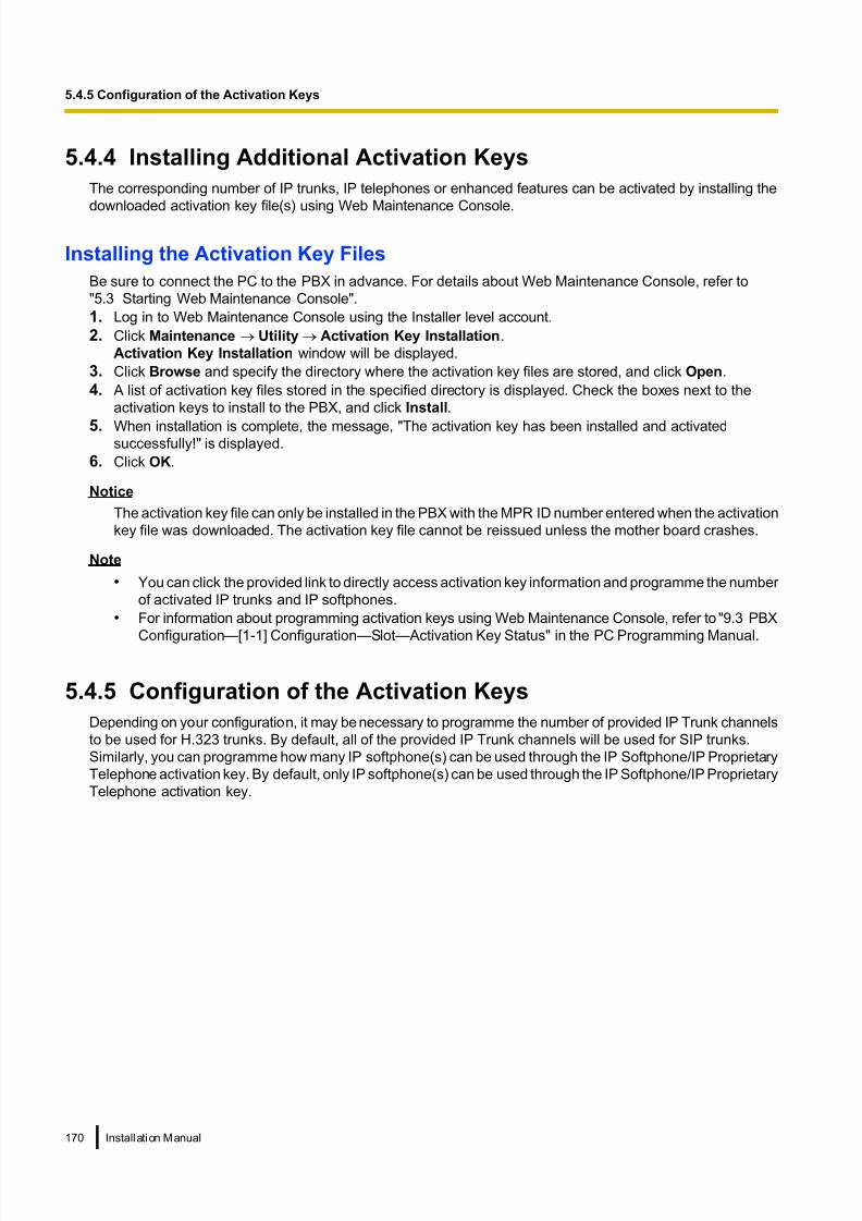
8/18/2019 NS500 Installation Manual
http://slidepdf.com/reader/full/ns500-installation-manual 170/300
5.4.4 Installing Additional Activation Keys
The corresponding number of IP trunks, IP telephones or enhanced features can be activated by installing the
downloaded activation key file(s) using Web Maintenance Console.
Installing the Activation Key Files
Be sure to connect the PC to the PBX in advance. For details about Web Maintenance Console, refer to
"5.3 Starting Web Maintenance Console".
1. Log in to Web Maintenance Console using the Installer level account.
2. Click Maintenance ® Utility ® Activation Key Installation.
Activation Key Installation window will be displayed.
3. Click Browse and specify the directory where the activation key files are stored, and click Open.
4. A list of activation key files stored in the specified directory is displayed. Check the boxes next to the
activation keys to install to the PBX, and click Install.
5. When installation is complete, the message, "The activation key has been installed and activatedsuccessfully!" is displayed.
6. Click OK.
Notice
The activation key file can only be installed in the PBX with the MPR ID number entered when the activation
key file was downloaded. The activation key file cannot be reissued unless the mother board crashes.
Note
• You can click the provided link to directly access activation key information and programme the number
of activated IP trunks and IP softphones.
• For information about programming activation keys using Web Maintenance Console, refer to "9.3 PBX
Configuration—[1-1] Configuration—Slot—Activation Key Status" in the PC Programming Manual.
5.4.5 Configuration of the Activation Keys
Depending on your configuration, it may be necessary to programme the number of provided IP Trunk channels
to be used for H.323 trunks. By default, all of the provided IP Trunk channels will be used for SIP trunks.
Similarly, you can programme how many IP softphone(s) can be used through the IP Softphone/IP Proprietary
Telephone activation key. By default, only IP softphone(s) can be used through the IP Softphone/IP Proprietary
Telephone activation key.
170 Installation Manual
5.4.5 Configuration of the Activation Keys

8/18/2019 NS500 Installation Manual
http://slidepdf.com/reader/full/ns500-installation-manual 171/300
1. a. Click Setup ® PBX Configuration ®
Configuration ® Slot.
b. Click Activation Key.
2. a. In Number of activated IP-GW, type the number of
IP Trunk channels to be used for H.323 trunks.
Note
If you have changed the value for Number of
activated IP-GW, you must click Execute to
restart the V-IPGW16 cards for the change to
take effect.
b. In Number of activated IP-Softphone, type the
number of IP softphones to be used through the IP
Softphone/IP Proprietary Telephone activation key.
3. Click OK.
Installation Manual 171
5.4.5 Configuration of the Activation Keys
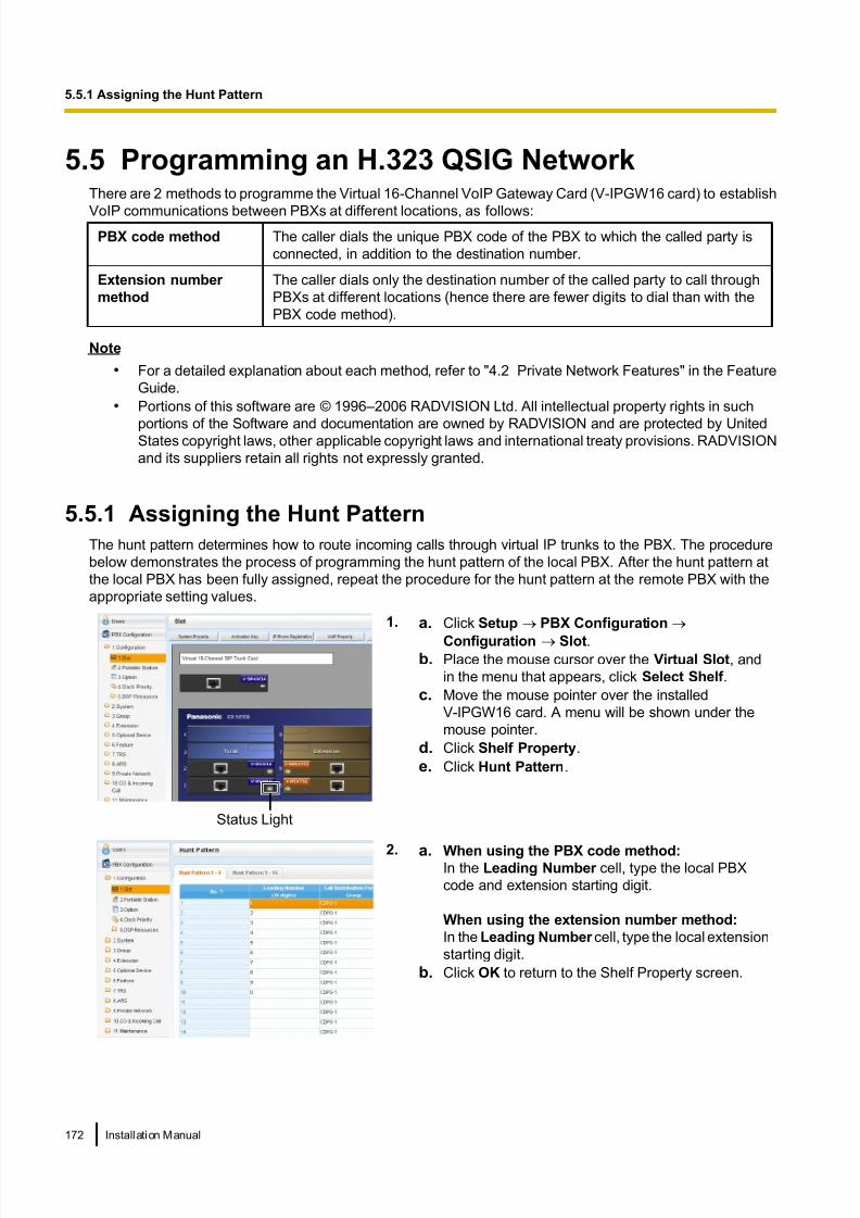
8/18/2019 NS500 Installation Manual
http://slidepdf.com/reader/full/ns500-installation-manual 172/300
5.5 Programming an H.323 QSIG NetworkThere are 2 methods to programme the Virtual 16-Channel VoIP Gateway Card (V-IPGW16 card) to establish
VoIP communications between PBXs at different locations, as follows:
PBX code method The caller dials the unique PBX code of the PBX to which the called party is
connected, in addition to the destination number.
Extension number
method
The caller dials only the destination number of the called party to call through
PBXs at different locations (hence there are fewer digits to dial than with the
PBX code method).
Note
• For a detailed explanation about each method, refer to "4.2 Private Network Features" in the Feature
Guide.
• Portions of this software are © 1996–2006 RADVISION Ltd. All intellectual property rights in such
portions of the Software and documentation are owned by RADVISION and are protected by UnitedStates copyright laws, other applicable copyright laws and international treaty provisions. RADVISION
and its suppliers retain all rights not expressly granted.
5.5.1 Assigning the Hunt Pattern
The hunt pattern determines how to route incoming calls through virtual IP trunks to the PBX. The procedure
below demonstrates the process of programming the hunt pattern of the local PBX. After the hunt pattern at
the local PBX has been fully assigned, repeat the procedure for the hunt pattern at the remote PBX with the
appropriate setting values.
Status Light
1. a. Click Setup ® PBX Configuration ®
Configuration ® Slot.b. Place the mouse cursor over the Virtual Slot, and
in the menu that appears, click Select Shelf .
c. Move the mouse pointer over the installed
V-IPGW16 card. A menu will be shown under the
mouse pointer.
d. Click Shelf Property.
e. Click Hunt Pattern.
2. a. When using the PBX code method:In the Leading Number cell, type the local PBX
code and extension starting digit.
When using the extension number method:
In the Leading Number cell, type the local extension
starting digit.
b. Click OK to return to the Shelf Property screen.
172 Installation Manual
5.5.1 Assigning the Hunt Pattern
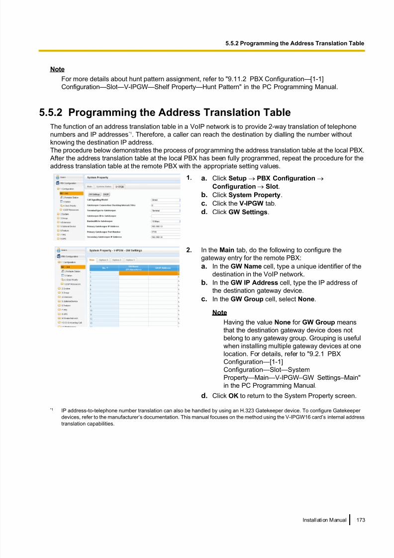
8/18/2019 NS500 Installation Manual
http://slidepdf.com/reader/full/ns500-installation-manual 173/300
Note
For more details about hunt pattern assignment, refer to "9.11.2 PBX Configuration—[1-1]
Configuration—Slot—V-IPGW—Shelf Property—Hunt Pattern" in the PC Programming Manual.
5.5.2 Programming the Address Translation Table
The function of an address translation table in a VoIP network is to provide 2-way translation of telephone
numbers and IP addresses*1. Therefore, a caller can reach the destination by dialling the number without
knowing the destination IP address.
The procedure below demonstrates the process of programming the address translation table at the local PBX.
After the address translation table at the local PBX has been fully programmed, repeat the procedure for the
address translation table at the remote PBX with the appropriate setting values.
1. a. Click Setup ® PBX Configuration ®
Configuration ® Slot.
b. Click System Property.c. Click the V-IPGW tab.
d. Click GW Settings.
2. In the Main tab, do the following to configure the
gateway entry for the remote PBX:
a. In the GW Name cell, type a unique identifier of the
destination in the VoIP network.
b. In the GW IP Address cell, type the IP address of
the destination gateway device.c. In the GW Group cell, select None.
Note
Having the value None for GW Group means
that the destination gateway device does not
belong to any gateway group. Grouping is useful
when installing multiple gateway devices at one
location. For details, refer to "9.2.1 PBX
Configuration—[1-1]
Configuration—Slot—System
Property—Main—V-IPGW–GW Settings–Main"
in the PC Programming Manual.
d. Click OK to return to the System Property screen.
*1 IP address-to-telephone number translation can also be handled by using an H.323 Gatekeeper device. To configure Gatekeeper
devices, refer to the manufacturer’s documentation. This manual focuses on the method using the V-IPGW16 card’s internal address
translation capabilities.
Installation Manual 173
5.5.2 Programming the Address Translation Table

8/18/2019 NS500 Installation Manual
http://slidepdf.com/reader/full/ns500-installation-manual 174/300
3. a. Click Setup ® PBX Configuration ®
Configuration ® Slot.
b. Click System Property.
c. Click the V-IPGW tab.d. Click DN2IP.
e. When using the PBX code method:
In the Leading Number cell, type the remote PBX
code and starting digit of destination extension.
When using the extension number method:
In the Leading Number cell, type the remote PBX
code and starting digit of destination extension.
f. In the Remaining Number of Digits cell, type a
number of digits to dial following the leading number.
g. In GW No./GW Group Selection, select GW No.
h. In the GW No. cell, select 1 (the gateway entry for the destination gateway device at the remote PBX).
i. Click OK.
Note
For more details about gateway settings, refer to "9.2.1 PBX Configuration—[1-1]
Configuration—Slot—System Property—Main—V-IPGW–GW Settings–Main" in the PC Programming
Manual.
174 Installation Manual
5.5.2 Programming the Address Translation Table

8/18/2019 NS500 Installation Manual
http://slidepdf.com/reader/full/ns500-installation-manual 175/300
5.5.3 Programming the Network Settings
For successful operation of a VoIP network using the V-IPGW16 card, network settings for the PBX at each
location must be programmed appropriately. For a detailed discussion of related features, refer to the Feature
Guide.
This section details the procedure to programme the network settings for the local PBX. After the programming
for the local PBX has been done, repeat the procedure for the remote PBX with the appropriate setting values.
The following procedures describe the process of programming the network settings for each numbering
method.
Programming for the PBX Code Method
1. a. Click Setup ® PBX Configuration ® CO &
Incoming Call.
b. Click CO Line Settings.
c. Type the CO Name and assign an unused TrunkGroup Number to be used for all IP trunks.
d. Click OK.
2. Note
Before changing Numbering Plan settings, when a
V-SIPEXT32 card or V-UTEXT32 card is installed,
change the status of the card(s) to OUS.
a. Click Setup ® PBX Configuration ® System.b. Click Numbering Plan.
c. Click Main.
d. Click the Features tab.
e. In the TIE Line Access cell, type the dialling
number.
f. Click OK.
3. a. Click Setup ® PBX Configuration ® Private
Network.
b. Click TIE Table.
c. In the Own PBX Code cell, type the PBX code of the
local PBX in the network.d. In the first unused Leading Number cell, type the
PBX code of the remote PBX in the network.
e. In the corresponding Trunk Group list, select the
number of the trunk group to be used when making
calls.
f. If it is necessary to add number(s) to the input
number, enter the number(s) to be added in the
desired Added Number cell.
If it is necessary to delete number(s) from the input
number, enter the number(s) to be deleted in the
desired Removed Number of Digits cell.
g. Click OK.
Installation Manual 175
5.5.3 Programming the Network Settings

8/18/2019 NS500 Installation Manual
http://slidepdf.com/reader/full/ns500-installation-manual 176/300
Programming for the Extension Number Method
1. a. Click Setup ® PBX Configuration ® CO &
Incoming Call.
b. Click CO Line Settings.
c. Type the CO Name and assign an unused Trunk
Group Number to be used for all IP trunks.
d. Click OK.
2. Note
Before changing Numbering Plan settings, when a
V-SIPEXT32 card or V-UTEXT32 card is installed,
change the status of the card(s) to OUS.
a. Click Setup ® PBX Configuration ® System.
b. Click Numbering Plan.
c. Click Main.
d. Click the Other PBX Extension tab.
e. In the Dial (3 digits) cell, type a starting digit of
destination extension.
f. Click OK.
3. a. Click Setup ® PBX Configuration ® Private
Network.
b. Click TIE Table.
c. In the Leading Number cell, type the starting digit
of destination extension.
d. Click OK.
Note
For details about network parameter settings, refer to the relevant sections of the PC Programming Manual.
176 Installation Manual
5.5.3 Programming the Network Settings

8/18/2019 NS500 Installation Manual
http://slidepdf.com/reader/full/ns500-installation-manual 177/300
5.6 Programming SIP TrunksThe Virtual 16-Channel SIP Trunk Card (V-SIPGW16) is a virtual trunk card which is designed to be easily
integrated into an Internet Telephony Service provided by an ITSP (Internet Telephony Service Provider).Various settings can be programmed for each virtual SIP gateway port.
Accessing Port Properties
1. Click Setup ® PBX Configuration ® Configuration
® Slot.
2. Place the mouse cursor over the Virtual Slot, and in the
menu that appears, click Select Shelf .
3. Move the mouse pointer over the V-SIPGW16 card to
display the menu of options, and then click Ous.
4. Move the mouse pointer over the V-SIPGW16 card to
display the menu of options again, and then click Port
Property.
Programming Port Properties
Automatic Programming
Some of the parameters can be automatically programmed by selecting the desired SIP provider for each
virtual SIP gateway port. Available SIP providers can be selected, and a different SIP provider can be assigned
to each virtual SIP gateway port.
Note
It is necessary to import a SIP provider list file (comma-separated value [CSV] file) in advance to use the
automatic programming feature.
Follow the steps below to configure a SIP provider.
1. Click Select Provider .
A dialogue box will appear. Available virtual SIP gateway port numbers are displayed in the list.
2. From the Provider menu, select the desired SIP provider.
Note
If the desired SIP provider is not shown in the drop-down list, it is necessary to programme the desired
parameters manually. For information about the manual programming procedure, refer to "Manual
Programming" below.
3. Highlight the desired port numbers or click Select All to select all the virtual SIP gateway port numbers to
be assigned to the SIP provider selected in step 2.
4. Click Execute.
Appropriate setting values designated by the SIP provider will be set in the parameters for the virtual SIP
gateway ports.
Installation Manual 177
5.6 Programming SIP Trunks

8/18/2019 NS500 Installation Manual
http://slidepdf.com/reader/full/ns500-installation-manual 178/300
Manual Programming
Follow the steps below to programme the parameters which are not automatically programmed by selecting a
provider.
1. Click the desired tab.2. Enter information or select settings from the drop-down list for each parameter.
Parameters that Require Manual Programming
Manual programming is compulsory for the following parameters:
• User Name: Specifies the user name (SIP Account) provided by the SIP provider. (Max. 64 characters)
• Authentication ID: Specifies the authentication ID required for registration with the SIP server. (Max. 64
characters)
• Authentication Password: Specifies the authentication password used for registration with the SIP
provider. (Max. 32 characters)
Follow the steps below to programme these 3 parameters.
1. Click an Account tab.
2. In the User Name column, enter the user name provided
by the SIP provider.
3. In the Authentication ID column, enter the
authentication ID required for registration with the SIP
server.
4. In the Authentication Password column, the
authentication password used for registration with the
SIP provider.
5. Click OK.
Adding Settings to Provider Profiles
Follow the steps below to add the settings to provider profiles.
1. Click Add Provider .
A dialogue box will appear. Available virtual SIP gateway
port numbers are displayed in the list.
2. Highlight the desired port numbers or click Select All to
select all the virtual SIP gateway port numbers to add
the settings to provider profiles.
3. Click Execute.
Note
For more details about SIP gateway port settings, refer to the PC Programming Manual.
178 Installation Manual
5.6 Programming SIP Trunks

8/18/2019 NS500 Installation Manual
http://slidepdf.com/reader/full/ns500-installation-manual 179/300
5.7 Assigning Networking Information to IP
Telephones
5.7.1 Assigning IP Addressing Information
The IP telephone’s IP address, subnet mask address and default gateway address, and the PBX’s IP address
must be assigned to the IP telephone before it can be used on the network. This IP addressing information
can be assigned in the following ways:
For IP-PTs
• Using a DHCP server (DHCP Server feature or an external DHCP server) when the IP-PT is on the
same LAN as the PBX
The DHCP server automatically assigns the IP address of the IP-PT, the subnet mask address, and thedefault gateway address to the IP-PT.
The PBX’s IP address can also be assigned automatically to the IP-PT in the process of being registered
to the PBX. For details about registering the IP-PT, refer to "5.8.1 Registering IP Telephones".
Note
For information about the DHCP Server feature, refer to "8.1.2 DHCP (Dynamic Host Configuration
Protocol) Server".
• Using a DHCP server (DHCP Server feature or an external DHCP server) when the IP-PT is on a
remote office LAN
While the DHCP server automatically assigns the IP address of the IP-PT, the subnet mask address, and
the default gateway address to the IP-PT, the PBX’s IP address must be assigned manually.
Follow the procedure below to assign the PBX’s IP address.If you need to set VLAN parameters, follow the procedure described in "5.7.2 Setting VLAN
Parameters" after assigning the IP addresses, without ending programming.
Note
• By assigning the PBX’s IP address to one IP-PT, it is possible to assign the PBX’s IP address to
other IP-PTs or IP-CSs on the same LAN through system programming. For details, refer to
"9.14 PBX Configuration—[1-1] Configuration—Slot—V-IPEXT—Port Property—Option—
Announce Mode" in the PC Programming Manual.
• IP-PTs can only receive IP addressing information from a DHCP server on its own LAN. Therefore,
when IP-PTs are located on several LANs, a DHCP server is required on each LAN.
• Since the default setting of the DHCP client function is enabled for IP-PTs, simply connect the
IP-PTs to the LAN to use the DHCP server.• For KX-NT511 Users
Since there is no PROGRAM button on a KX-NT511, press flexible button 1, 2, or 3 instead.
Also,there is no Navigator key either. To select items on the LCD, use flexible button 1 for left-arrow
operation and flexible button 3 for right-arrow operation.
Installation Manual 179
5.7.1 Assigning IP Addressing Information

8/18/2019 NS500 Installation Manual
http://slidepdf.com/reader/full/ns500-installation-manual 180/300
KX-NT300 series (except KX-NT321) and KX-NT500 series (except KX-NT511 and KX-NT551)
PBX IP Address
ENTER ENTER
Select "PBX". Select "PBX IP Address". Select "Primary PBX".ENTER ENTER
To enter the IP address of the PBX
Press "SETUP"when it is displayed.
SETUP
To start programming
Supply power to the IP-PT.
To enter the IP address of the Secondary PBX*2
PBX IP Address
Select "Secondary PBX". ENTER ENTER
To the VLAN settings
Press "STORE".
To end programming
To set VLAN parameters
OR
The IP-PT will rebootand can then be
registered to the PBX.
STORE
Return to theMenu screen.
*1
*1 For KX-NT300 series: Software version 2.00 or later only
For KX-NT500 series: Software version 1.00 or later only*2 Optional for KX-NT300 series (Software version 2.00 or later only) and KX-NT500 series (Software version 1.00 or later only)
Note
The illustrations may differ from the buttons on your telephone.
180 Installation Manual
5.7.1 Assigning IP Addressing Information

8/18/2019 NS500 Installation Manual
http://slidepdf.com/reader/full/ns500-installation-manual 181/300
KX-NT321/KX-NT511/KX-NT551
Press PROGRAMwhile "Searching" is displayed.
To start programming
Supply power to the IP-PT.
To enter the IP address of the PBX
To the VLAN settings
The IP-PT will rebootand can then be
registered to the PBX.
To end programming
To set VLAN parameters
OR
Press HOLD twice to returnto the Menu screen.
Select "PBX IP Address".
Press SP-PHONE.
Press SP-PHONE.
Press STORE.
Select "PBX". Press SP-PHONE.
Press SP-PHONE.
Select "PrimaryPBX".
Press SP-PHONE.
Select "SecondaryPBX".
Press SP-PHONE.
To enter the IP address of the Secondary PBX (if required)
PBX IP Address
PBX IP Address
Note
• For KX-NT511 Users
For details about operating the PROGRAM button and other buttons, refer to "For IP-PTs" in
"5.7.1 Assigning IP Addressing Information".
• To confirm the connection to the secondary PBX after assigning IP addressing information, (1) turn
the IP-PT’s power off, and (2) hold the STORE button and 2 key while turning the power on.
Installation Manual 181
5.7.1 Assigning IP Addressing Information

8/18/2019 NS500 Installation Manual
http://slidepdf.com/reader/full/ns500-installation-manual 182/300
KX-NT265 (Software version 2.00 or later only)
PBX IP
Address
To enter the IP address of the PBX
Press PROGRAMwhile "Searching" is displayed.
To start programming
Supply power to the IP-PT.
PROG.
Press HOLD to returnto the Menu screen.
HOLD
Press VOLUMEto select "PBX".
VOL
Press SP-PHONEtwice.
Press SP-PHONE.
To the VLAN settings
The IP-PT will rebootand can then be
registered to the PBX.
To end programming
To set VLAN parameters
OR
Press STORE.
182 Installation Manual
5.7.1 Assigning IP Addressing Information

8/18/2019 NS500 Installation Manual
http://slidepdf.com/reader/full/ns500-installation-manual 183/300
• Not using a DHCP server (DHCP Server feature or an external DHCP server) when the IP-PT is on
the same LAN as the PBX
Only the PBX’s IP address can be assigned automatically to the IP-PT in the process of being registered
to the PBX. For details about registering the IP-PT, refer to "5.8.1 Registering IP Telephones".
Follow the procedure below to assign the IP address of the IP-PT, the subnet mask address, and the default
gateway address manually.
If you need to set VLAN parameters, follow the procedure described in "5.7.2 Setting VLAN
Parameters" after assigning the IP addresses, without ending programming.
KX-NT300 series (except KX-NT321) and KX-NT500 series (except KX-NT511 and KX-NT551)
Select "Network". ENTER Select "Disable"for DHCP setting.
ENTER
IP Address*1
ENTER
To set the IP address of the IP-PT
Select "Default Gateway". ENTER
Default Gateway Address*3
ENTER
To set the default gateway address (if required)
To set the subnet mask address
Select "Subnet Mask". ENTER
Subnet Mask Address*2
ENTER
Select "IP Address".
To start programming
Press "SETUP" when it is displayed.
SETUP
Supply power to the IP-PT.
Return to theMenu screen.
To enter the IP address of the Secondary PBX*4
PBX IP Address
ENTER ENTER
Select "PBX". Select "PBX IP Address".
ENTER ENTER Select "SecondaryPBX".
Continued on next page
Installation Manual 183
5.7.1 Assigning IP Addressing Information

8/18/2019 NS500 Installation Manual
http://slidepdf.com/reader/full/ns500-installation-manual 184/300
To the VLAN settings
Press "STORE".
STORE
To end programming
To set VLAN parameters
OR
The IP-PT will rebootand can then be
registered to the PBX.
Return to theMenu screen.
Return to theMenu screen.
Continued from previous page
*1 Valid IP address range: "1.0.0.0" to "223.255.255.255"*2 Valid subnet mask address range: "0–255.0–255.0–255.0–255" (except "0.0.0.0" and "255.255.255.255")*3 Valid IP address range: "1.0.0.0" to "223.255.255.255"*4 Optional for KX-NT300 series (Software version 2.00 or later only) and KX-NT500 series (Software version 1.00 or later only)
Note
The illustrations may differ from the buttons on your telephone.
184 Installation Manual
5.7.1 Assigning IP Addressing Information

8/18/2019 NS500 Installation Manual
http://slidepdf.com/reader/full/ns500-installation-manual 185/300
KX-NT321/KX-NT511/KX-NT551
IP Address*1
Subnet Mask Address*2
Default Gateway Address*3
To set the IP address of the IP-PT
To set the subnet mask address
To set the default gateway address (if required)
To start programming
Supply power to the IP-PT.
Press PROGRAMwhile "Searching" is displayed.
Select "Network". Press SP-PHONE. Select "DHCP (Disable)". Press SP-PHONEtwice.
Press SP-PHONE.
Select "Subnet Mask". Press SP-PHONE. Press SP-PHONE.
Select "Default GW". Press SP-PHONE. Press SP-PHONE.
Press HOLD to returnto the Menu screen.
To enter the IP address of the Secondary PBX (if required)
Select "PBX IP Address".
Press SP-PHONE.Select "PBX". Press SP-PHONE. Select "SecondaryPBX".
Press SP-PHONE. Press SP-PHONE.
PBX IP Address
Press HOLD twice to return to the Menu screen.
Continued on next page
Installation Manual 185
5.7.1 Assigning IP Addressing Information

8/18/2019 NS500 Installation Manual
http://slidepdf.com/reader/full/ns500-installation-manual 186/300
Continued from previous page
To the VLAN settings
The IP-PT will rebootand can then be
registered to the PBX.
To end programming
To set VLAN parameters
OR
Press STORE.
*1 Valid IP address range: "1.0.0.0" to "223.255.255.255"*2 Valid subnet mask address range: "0–255.0–255.0–255.0–255" (except "0.0.0.0" and "255.255.255.255")*3 Valid IP address range: "1.0.0.0" to "223.255.255.255"
Note
• For KX-NT511 Users
For details about operating the PROGRAM button and other buttons, refer to "For IP-PTs" in
"5.7.1 Assigning IP Addressing Information".
• To confirm the connection to the secondary PBX after assigning IP addressing information, (1) turn
the IP-PT’s power off, and (2) hold the STORE button and 2 key while turning the power on.
186 Installation Manual
5.7.1 Assigning IP Addressing Information
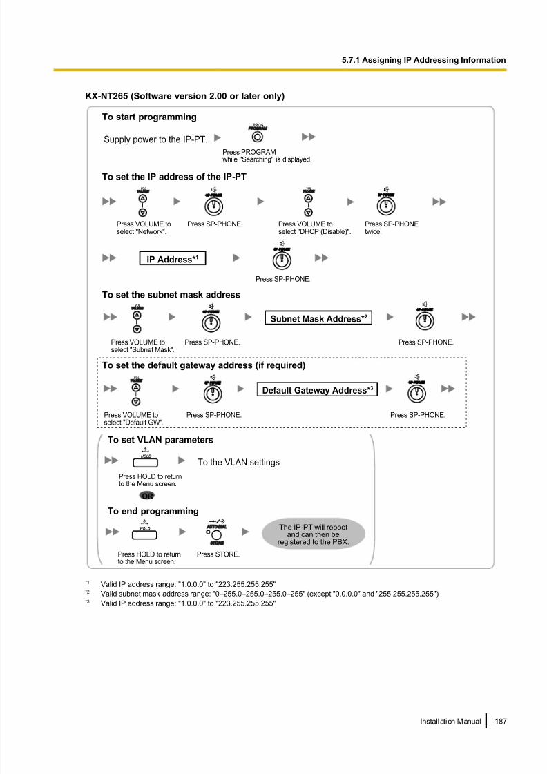
8/18/2019 NS500 Installation Manual
http://slidepdf.com/reader/full/ns500-installation-manual 187/300
KX-NT265 (Software version 2.00 or later only)
IP Address*1
Subnet Mask Address*2
Default Gateway Address*3
To set the IP address of the IP-PT
To set the subnet mask address
To set the default gateway address (if required)
To start programming
Supply power to the IP-PT.
Press PROGRAMwhile "Searching" is displayed.
PROG.
Press VOLUME toselect "Network".
VOL
Press SP-PHONE. Press VOLUME toselect "DHCP (Disable)".
VOL
Press SP-PHONEtwice.
Press SP-PHONE.
Press VOLUME toselect "Subnet Mask".
VOL
Press SP-PHONE. Press SP-PHONE.
Press VOLUME toselect "Default GW".
VOL
Press SP-PHONE. Press SP-PHONE.
To the VLAN settings
The IP-PT will rebootand can then be
registered to the PBX.
To end programming
To set VLAN parameters
OR
Press STORE.Press HOLD to returnto the Menu screen.
HOLD
Press HOLD to returnto the Menu screen.
HOLD
*1 Valid IP address range: "1.0.0.0" to "223.255.255.255"*2 Valid subnet mask address range: "0–255.0–255.0–255.0–255" (except "0.0.0.0" and "255.255.255.255")*3 Valid IP address range: "1.0.0.0" to "223.255.255.255"
Installation Manual 187
5.7.1 Assigning IP Addressing Information

8/18/2019 NS500 Installation Manual
http://slidepdf.com/reader/full/ns500-installation-manual 188/300
• Not using a DHCP server (DHCP Server feature or an external DHCP server) when the IP-PT is on
a remote office LAN
All of the IP addressing information must be assigned manually.
Follow the procedure below to assign the IP addressing information.
If you need to set VLAN parameters, follow the procedure described in "5.7.2 Setting VLAN
Parameters" after assigning the IP addresses, without ending programming.
Note
By assigning the PBX’s IP address to one IP-PT, it is possible to assign the PBX’s IP address to other
IP-PTs or IP-CSs on the same LAN through system programming. For details, refer to "9.14 PBX
Configuration—[1-1] Configuration—Slot—V-IPEXT—Port Property—Option— Announce Mode" in
the PC Programming Manual.
188 Installation Manual
5.7.1 Assigning IP Addressing Information
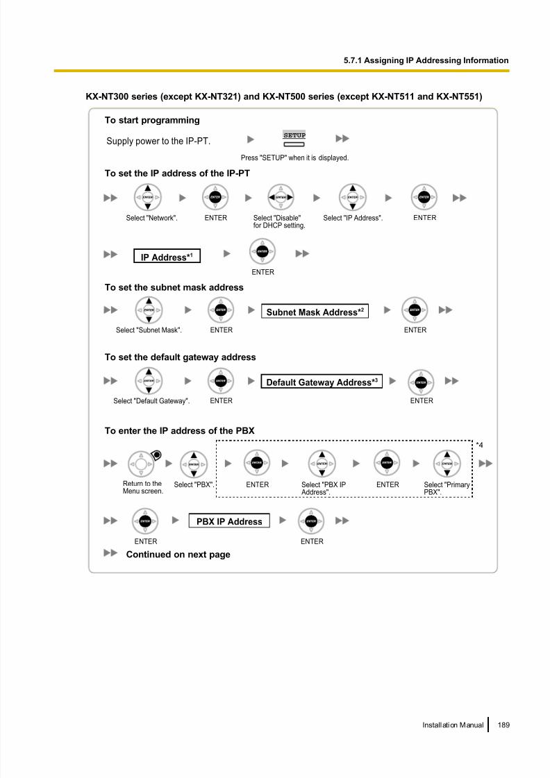
8/18/2019 NS500 Installation Manual
http://slidepdf.com/reader/full/ns500-installation-manual 189/300
KX-NT300 series (except KX-NT321) and KX-NT500 series (except KX-NT511 and KX-NT551)
Select "Network". ENTER Select "Disable"for DHCP setting.
ENTER
IP Address*1
ENTER
To set the IP address of the IP-PT
To set the subnet mask address
To set the default gateway address
Select "Default Gateway". ENTER
Default Gateway Address*3
ENTER
ENTER
Subnet Mask Address*2
ENTERSelect "Subnet Mask".
Select "IP Address".
To start programming
Press "SETUP" when it is displayed.
SETUPSupply power to the IP-PT.
Select "PBX".Return to theMenu screen.
PBX IP Address
ENTER ENTER
To enter the IP address of the PBX
Select "PBX IP Address".
Select "PrimaryPBX".
ENTER ENTER
Continued on next page
*4
Installation Manual 189
5.7.1 Assigning IP Addressing Information
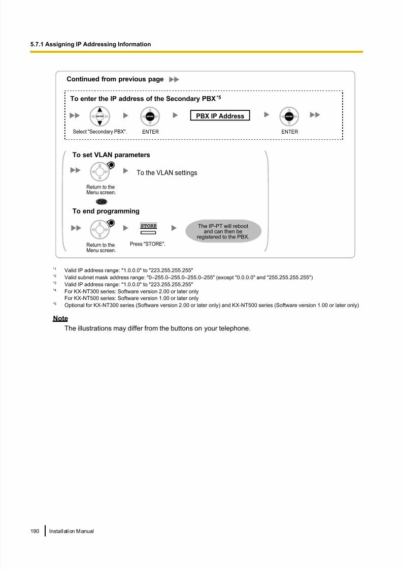
8/18/2019 NS500 Installation Manual
http://slidepdf.com/reader/full/ns500-installation-manual 190/300
To enter the IP address of the Secondary PBX*5
PBX IP Address
Select "Secondary PBX". ENTER ENTER
Continued from previous page
To the VLAN settings
Press "STORE".
STORE
To end programming
To set VLAN parameters
OR
The IP-PT will rebootand can then be
registered to the PBX.
Return to theMenu screen.
Return to theMenu screen.
*1 Valid IP address range: "1.0.0.0" to "223.255.255.255"*2 Valid subnet mask address range: "0–255.0–255.0–255.0–255" (except "0.0.0.0" and "255.255.255.255")*3 Valid IP address range: "1.0.0.0" to "223.255.255.255"*4 For KX-NT300 series: Software version 2.00 or later only
For KX-NT500 series: Software version 1.00 or later only*5 Optional for KX-NT300 series (Software version 2.00 or later only) and KX-NT500 series (Software version 1.00 or later only)
Note
The illustrations may differ from the buttons on your telephone.
190 Installation Manual
5.7.1 Assigning IP Addressing Information

8/18/2019 NS500 Installation Manual
http://slidepdf.com/reader/full/ns500-installation-manual 191/300
KX-NT321/KX-NT511/KX-NT551
IP Address*1
Subnet Mask Address*2
Default Gateway Address*3
To set the IP address of the IP-PT
To set the subnet mask address
To set the default gateway address
To start programming
Supply power to the IP-PT.
Press PROGRAMwhile "Searching" is displayed.
Select "Network". Press SP-PHONE. Select "DHCP (Disable)". Press SP-PHONEtwice.
Press SP-PHONE.
Select "Subnet Mask". Press SP-PHONE. Press SP-PHONE.
Select "Default GW". Press SP-PHONE. Press SP-PHONE.
Continued on next page
Press HOLD to returnto the Menu screen.
To enter the IP address of the PBX
Select "PBX IP Address".
Press SP-PHONE.Select "PBX". Press SP-PHONE. Select "PrimaryPBX".
Press SP-PHONE. Press SP-PHONE.
Press SP-PHONE.Select "SecondaryPBX".
Press SP-PHONE.
To enter the IP address of the Secondary PBX (if required)
PBX IP Address
PBX IP Address
Installation Manual 191
5.7.1 Assigning IP Addressing Information
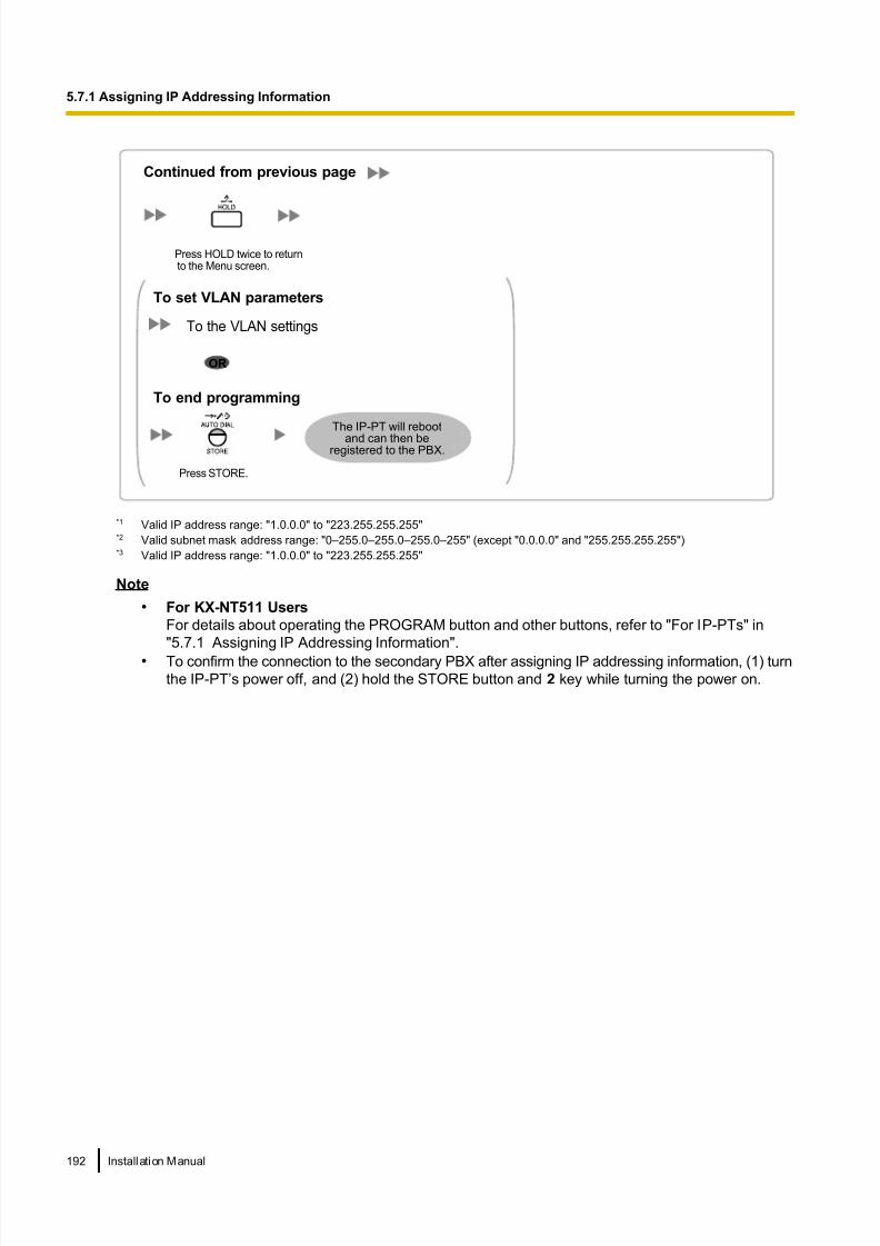
8/18/2019 NS500 Installation Manual
http://slidepdf.com/reader/full/ns500-installation-manual 192/300
Continued from previous page
To the VLAN settings
The IP-PT will reboot
and can then beregistered to the PBX.
To end programming
To set VLAN parameters
OR
Press HOLD twice to return to the Menu screen.
Press STORE.
*1 Valid IP address range: "1.0.0.0" to "223.255.255.255"*2 Valid subnet mask address range: "0–255.0–255.0–255.0–255" (except "0.0.0.0" and "255.255.255.255")*3 Valid IP address range: "1.0.0.0" to "223.255.255.255"
Note
• For KX-NT511 Users
For details about operating the PROGRAM button and other buttons, refer to "For IP-PTs" in
"5.7.1 Assigning IP Addressing Information".
• To confirm the connection to the secondary PBX after assigning IP addressing information, (1) turn
the IP-PT’s power off, and (2) hold the STORE button and 2 key while turning the power on.
192 Installation Manual
5.7.1 Assigning IP Addressing Information

8/18/2019 NS500 Installation Manual
http://slidepdf.com/reader/full/ns500-installation-manual 193/300
KX-NT265 (Software version 2.00 or later only)
IP Address*1
Subnet Mask Address*2
Default Gateway Address*3
To set the IP address of the IP-PT
To set the subnet mask address
To set the default gateway address
To enter the IP address of the PBX
To start programming
Supply power to the IP-PT.
Press PROGRAMwhile "Searching" is displayed.
PROG.
Press VOLUME toselect "Network".
VOL
Press SP-PHONE. Press VOLUME toselect "DHCP (Disable)".
VOL
Press SP-PHONEtwice.
Press SP-PHONE.
Press VOLUME toselect "Subnet Mask".
VOL
Press SP-PHONE. Press SP-PHONE.
Press VOLUME toselect "Default GW".
VOL
Press SP-PHONE. Press SP-PHONE.
Press HOLDtwice to returnto the Menu screen.
HOLD
Press VOLUMEto select "PBX".
VOL
Press SP-PHONEtwice.
PressSP-PHONE.
To the VLAN settings
The IP-PT will rebootand can then be
registered to the PBX.
To end programming
To set VLAN parameters
OR
Press STORE.
PBX IP
Address
Press HOLDto return to theMenu screen.
HOLD
*1 Valid IP address range: "1.0.0.0" to "223.255.255.255"*2 Valid subnet mask address range: "0–255.0–255.0–255.0–255" (except "0.0.0.0" and "255.255.255.255")*3 Valid IP address range: "1.0.0.0" to "223.255.255.255"
Installation Manual 193
5.7.1 Assigning IP Addressing Information

8/18/2019 NS500 Installation Manual
http://slidepdf.com/reader/full/ns500-installation-manual 194/300
For KX-UT Series SIP Phones
Notice
When you want to use a KX-UT series SIP phone that has already been used with another PBX, or that
has had its settings programmed, you must reset the SIP phone to its factory default before assigning new
IP address information as detailed in the following procedure.
For details, refer to the documentation for the KX-UT series SIP phone.
Assigning the IP addressing information to the SIP phone
• Using a DHCP server (DHCP Server feature or an external DHCP server) to automate the assignment
of IP addressing information
The DHCP server automatically assigns the IP address of the SIP phone, the subnet mask address, and
the default gateway address to the SIP phone.
The PBX’s IP address can also be assigned automatically to the SIP phone in the process of being
registered to the PBX. For details about registering the SIP phone, refer to "5.8.1 Registering IP
Telephones".
Note
For information about the DHCP Server feature, refer to "8.1.2 DHCP (Dynamic Host Configuration
Protocol) Server".
• Not using a DHCP server (DHCP Server feature or an external DHCP server) when assigning IP
addressing information
Only the PBX’s IP address can be assigned automatically to the SIP phone in the process of being
registered to the PBX. For details about registering the SIP phone, refer to "5.8.1 Registering IP
Telephones". The IP address of the SIP phone, the subnet mask address, and the default gateway address
must be assigned manually. For instructions, refer to the documentation of the SIP phone.
Note
• When the PBX is not in the same network as the SIP phone, the IP address of the PBX must beassigned manually. For instructions for manually setting PBX network information, refer to
"Assigning the IP address of the PBX to a SIP phone".
• When assigning IP addressing information to the SIP phone, do not use the phone’s Web user
interface programming.
Assigning the IP address of the PBX to a SIP phone
The IP address of the PBX is automatically assigned to a SIP phone when the SIP phone is in the same LAN
as the PBX. However, when the SIP phone is in a different LAN from the PBX, the following procedure is
required to assign the IP address of the PBX manually using the Web user interface.
Notice
Do not perform any other operation rather than following procedure with the Web user interface. Otherwisethe SIP phone may not work properly. In that case, contact an authorised Panasonic Factory Service
Centre.
1. Prepare a configuration file to specify the IP address of the PBX.
When the SIP Phones are in a segment that uses NAT traversal
a. Open a text editor on a PC, and then write exactly same as the following:
194 Installation Manual
5.7.1 Assigning IP Addressing Information

8/18/2019 NS500 Installation Manual
http://slidepdf.com/reader/full/ns500-installation-manual 195/300
For standard connection
# PCC Standard Format File # DO NOT CHANGE THIS LINE!
### Management Server Settings ####### ACS_URL="http://xxx.xxx.xxx.xxx:yyy/cwmp/cwmpAction.cgi"
For secure connection
# PCC Standard Format File # DO NOT CHANGE THIS LINE!
### Management Server Settings #######
ACS_URL="http://xxx.xxx.xxx.xxx:yyy/cwmp/cwmpAction.cgi"
CFG_INT_CERTIFICATE_PATH=http://xxx.xxx.xxx.xxx:zzz/utdownload/KX-NS500
Notice
• For "xxx.xxx.xxx.xxx:yyy", enter the IP address and port number of the network router which is
in a same LAN with the PBX.
The router accessed by the SIP phone must have static NAT/NAPT settings enabled so that
the packets sent to xxx.xxx.xxx.xxx:yyy to be transferred to the PBX. For details, refer to
"Connection via Internet" in "5.2 PC Connection" and "Internet Connection (SSL
Connection):" in "5.3 Starting Web Maintenance Console".
• Configuration files must end with an empty line.
b. Save the text file as "UT_ACS.cfg".
When the SIP Phones are in a different segments of the same LAN
a. Log in to the Web Maintenance Console of the site where the SIP phones will be registered.b. Click Utility ® File ® File Transfer PBX to PC.
c. Select the config file (UT_ACS_xxyyyy.cfg), and then download it to your PC.
For more details about downloading files from a PBX to a PC, refer to "7.2.2 Utility—File—File Transfer
PBX to PC" in the PC Programming Manual.
Note
xx: Site ID (2 digits)
yyyy: Site name*1 (Up to 32 characters*2)*1 Spaces as well as the following characters in site names will be replaced with underscores.
/, :, *, ?, ", <, >, | (vertical bar), &, +*2 In some cases, the full site name may not be included in the file name even if it is less than 32 characters.
When the SIP Phones are in a different LAN (Remote site installation)
a. Log in to the Web Maintenance Console of the site where the SIP phones will be registered.
b. Click Utility ® File ® File Transfer PBX to PC.
c. Select the config file (UT_ACS_HTTPS_xxyyyy.cfg), and then download it to your PC.
Note
• xx: Site ID (2 digits)
yyyy: Site name*1 (Up to 32 characters*2)*1 Spaces as well as the following characters in site names will be replaced with underscores.
/, :, *, ?, ", <, >, | (vertical bar), &, +*2 In some cases, the full site name may not be included in the file name even if it is less than 32 characters.
• When SIP phones use the internet to communicate with the PBX, KX-NS500 uses the HTTPS
protocol for security.
Installation Manual 195
5.7.1 Assigning IP Addressing Information

8/18/2019 NS500 Installation Manual
http://slidepdf.com/reader/full/ns500-installation-manual 196/300
2. Confirm the IP address of the SIP phone.
For non-KX-UT670 telephones
a. Press Setting or Setup (soft button) on the SIP phone.
b. Select "Information Display", then press [ENTER].c. Select "IP address".
The IP address of the SIP phone will be displayed.
d. Press [CANCEL].
For KX-UT670 telephones
a. Tap the status bar.
For details about the status bar, refer to the documentation of the KX-UT670.
b. Tap Phone status.
The IP address of the SIP phone will be displayed.
c. Tap OK.
3. Open the port of the SIP phone, which is used by the PCs to access the Web user interface.
For non-KX-UT670 telephones
a. Press Setting or Setup (soft button) on the SIP phone.b. Press [#][5][3][4].
c. Select "On" for "Embedded web", then press [ENTER].
Note
If no operation are made for 30 minutes, the port will be closed again automatically.
For KX-UT670 telephones
a. On the Home screen, press .
b. Tap Settings.
c. Tap About Phone.
d. Touch and hold .
e. Press [#][5][3][4], and then press Enter.f. Select On for Embedded web.
Note
If no operation are made for 30 minutes, the port will be closed again automatically.
4. Access the Web user interface from the PC.
Note
If a KX-UT670 with software version 01.200 or lower is used with the KX-NS500, the KX-UT670 must
be reset to its factory default before you perform the following procedure. For details about resetting
the KX-UT670, refer to the documentation of the KX-UT670.
a. Open your Web browser, and then enter "http://"followed by the SIP phone’s IP address into the
address field of your browser.b. For authentication, enter your ID and password, and then click OK.
The Installer Level ID and Password are as follows.
ID: instoperatoruserid
Password: instpass
c. Select Maintenance ® Import Configuration File.
d. Click Browse… , and then select the UT_ACS configuration file. (UT_ACS.cfg or UT_ACS_xxyyyy.cfg)
e. Click Import.
196 Installation Manual
5.7.1 Assigning IP Addressing Information

8/18/2019 NS500 Installation Manual
http://slidepdf.com/reader/full/ns500-installation-manual 197/300
When the configuration file is successfully imported, the SIP phone starts to access the PBX
automatically.
5. Confirm if the configuration file was successfully loaded.
a. Select Maintenance ® Export Configuration File.
b. Click Export to download the configuration file being used currently on the SIP phone.
c. Compare the UT_ACS configuration file and the downloaded file. If the UT_ACS configuration file was
successfully loaded, the contents of those 2 files will be exactly the same.
Notice
When the 2 UT_ACS configuration files do not match, and if the SIP phone does not work properly,
contact an authorised Panasonic Factory Service Centre.
For Non-KX-UT Series SIP Phones
Using a DHCP server (DHCP Server feature or an external DHCP server) to automate the assignment
of IP addressing information
The IP address of the SIP phone, the subnet mask address, and the default gateway address can be assigned
to the SIP phone automatically by the DHCP server.
The PBX’s IP address must be assigned manually on the SIP phone side.
Installation Manual 197
5.7.1 Assigning IP Addressing Information

8/18/2019 NS500 Installation Manual
http://slidepdf.com/reader/full/ns500-installation-manual 198/300
For instructions, refer to the documentation of the SIP phone.
Not using a DHCP server (DHCP Server feature or an external DHCP server) when assigning IP
addressing information
All of the IP addressing information must be assigned manually.
For instructions, refer to the documentation of the SIP phone.
Note
• A SIP phone can only receive IP addressing information from a DHCP server on its own LAN. Therefore,
when SIP phones are located on several LANs, a DHCP server is required on each LAN.
• When the DHCP client function is enabled for SIP phones, simply connect them to the LAN to use the
DHCP server. For details about the DHCP client function setting, refer to the documentation of the SIP
phone.
198 Installation Manual
5.7.1 Assigning IP Addressing Information

8/18/2019 NS500 Installation Manual
http://slidepdf.com/reader/full/ns500-installation-manual 199/300
5.7.2 Setting VLAN Parameters
To establish voice communications between IP telephones, the primary ports of the IP telephones and the
connected PBX must belong to the same VLAN. Consult your network administrator and obtain the appropriate
VLAN ID.
If you are using an IP telephone equipped with two ports, it is possible to place primary and secondary ports
of the IP telephone on different VLANs by assigning separate VLAN IDs to each port.
Follow the procedure below for all IP-PTs on the network, using appropriate VLAN IDs.
Note
The procedure for SIP phones may vary depending on the type of the SIP phone being used. Refer to the
documentation of your SIP phone for instructions.
KX-NT300 series (except KX-NT321) and KX-NT500 series (except KX-NT511 and KX-NT551)
Select "VLAN". ENTER
ENTER
VLAN ID
ENTER
VLAN Priority*1
1
ENTER
Press "STORE".
STORE
To set the VLAN ID for the primary port
To set the VLAN ID for the secondary port
To end programming
0–7
1–40940-4094 (Only for KX-NT55x)
Select "Primary port".
ENTER
VLAN ID
ENTER
VLAN Priority*1
ENTER1–40940-4094 (Only for KX-NT55x)
Select"Secondary port (TO PC)".
Select "VLAN Priority". ENTER
Return to theVLAN setting screen.
ENTER
ENTER
Select"VLAN Priority".
ENTER
Return to theMenu screen.
Select "Enable" forVLAN setting.
Select "VLAN ID".
Select "VLAN ID".
0–7
After assigning
the IP addressesSelect "QoS". ENTER
The IP-PT will rebootand can then be
registered to the PBX.
*1 The VLAN priority of the primary port must be set higher than the priority of the secondary port. The larger the number, the higher
the priority.
Installation Manual 199
5.7.2 Setting VLAN Parameters

8/18/2019 NS500 Installation Manual
http://slidepdf.com/reader/full/ns500-installation-manual 200/300
Note
The illustrations may differ from the buttons on your telephone.
KX-NT321/KX-NT511/KX-NT551
To end programming
After assigning
the IP addressesSelect "QoS". Press SP-PHONE. Select "VLAN". Press SP-PHONE.
Press STORE.Press HOLD threetimes to return to theMenu screen.
Select "VLAN (Enable)". Press SP-PHONE.
VLAN ID
VLAN Priority*1
To set the VLAN ID for the primary port
0–7
1–40940-4094 (Only for KX-NT55x)
Select "Priority".
Select "VLAN (Primary)". Press SP-PHONE. Press SP-PHONE.Select "VLAN ID".
Press SP-PHONE.
To set the VLAN ID for the secondary port
VLAN ID
VLAN Priority*1
1–40940-4094 (Only for KX-NT55x)
0–7
Select "VLAN (Secondary)". Press SP-PHONE. Select "VLAN ID".
Select "Priority".
Press SP-PHONE.
Press SP-PHONE.
The IP-PT will rebootand can then be
registered to the PBX.
*1 The VLAN priority of the primary port must be set higher than the priority of the secondary port. The larger the number, the higher
the priority.
Note
• For KX-NT511 Users
For details about operating the PROGRAM button and other buttons, refer to "For IP-PTs" in
"5.7.1 Assigning IP Addressing Information".
200 Installation Manual
5.7.2 Setting VLAN Parameters

8/18/2019 NS500 Installation Manual
http://slidepdf.com/reader/full/ns500-installation-manual 201/300
KX-NT265 (Software version 2.00 or later only)
VLAN ID VLAN Priority
To end programming
0–71–4094
After assigningthe IP addresses
Press VOLUME toselect "VLAN".
VOL
Press VOLUME toselect "QoS".
VOL
Press SP-PHONE.Press SP-PHONE. Press VOLUME toselect "VLAN (Enable)".
VOL
Press SP-PHONE.Press SP-PHONE. Press SP-PHONE.
Press STORE.Press HOLD to returnto the Menu screen.
HOLD
The IP-PT will reboot
and can then beregistered to the PBX.
Installation Manual 201
5.7.2 Setting VLAN Parameters

8/18/2019 NS500 Installation Manual
http://slidepdf.com/reader/full/ns500-installation-manual 202/300
5.7.3 Setting LLDP Parameters
LLDP-MED is a technique for IP telephones to obtain VLAN settings automatically from a network device, such
as a Network Switch.
If you are using an IP telephone equipped with two LAN ports, the primary and secondary ports of the IP
telephone can be placed on different VLANs by assigning a separate VLAN ID to each port. Follow the
procedure below for all IP-PTs on the network, using appropriate VLAN IDs.
Note
• This feature is available only for KX-NT511, KX-NT551, KX-NT553, and KX-NT556 IP-PTs.
• VLAN settings configured through PT programming have priority over VLAN settings configured
through the LLDP-MED function.
• To enable or disable the sending of LLDP packets from KX-NS500, consult your dealer.
202 Installation Manual
5.7.3 Setting LLDP Parameters

8/18/2019 NS500 Installation Manual
http://slidepdf.com/reader/full/ns500-installation-manual 203/300
KX-NT553/KX-NT556
Select "LLDP". ENTER
ENTER
VLAN ID*1
ENTER
VLAN Priority*1*2
1
Press "STORE".
STORE
To set the VLAN ID for the primary port
To set the VLAN ID for the secondary port
To end programming
0–7
0–4094Select "Primary port".
ENTER
ENTER ENTER0–4094
Select"Secondary port".
Select "VLAN Priority". ENTER
Return to theLLDP setting screen.
ENTER
Select"VLAN Priority".
ENTER
Return to theMenu screen.
Select "Enable" forLLDP setting.
Select "VLAN ID".
Select "VLAN ID".
0–7
After assigning
the IP addressesSelect "QoS". ENTER
The IP-PT will rebootand can then be
registered to the PBX.
VLAN ID*1 VLAN Priority*1*2
To set the Interval time for LLDP
ENTER
ENTER
Select"LLDP (Secondary)".
Return to theLLDP setting screen.
ENTERSelect "LLDP (Interval)".
INTERVAL
1–3600
*1 The VLAN ID and the VLAN priority are set automatically for the primary port; these are reference only. However, the VLAN ID and
the VLAN priority for secondary port must be set manually.*2 The VLAN priority of the primary port must be set higher than the priority of the secondary port. The larger the number, the higher
the priority.
Installation Manual 203
5.7.3 Setting LLDP Parameters

8/18/2019 NS500 Installation Manual
http://slidepdf.com/reader/full/ns500-installation-manual 204/300
KX-NT511/KX-NT551
To end programming
After assigningthe IP addresses
Select "QoS". Press SP-PHONE. Select "LLDP". Press SP-PHONE.
Press STORE.Press HOLD threetimes to return to theMenu screen.
Select "Enable"for LLDP setting.
Press SP-PHONE.
VLAN ID*1
VLAN Priority*1*2
To set the VLAN ID for the primary port
0–7
Select "LLDP (Primary)". Press SP-PHONE. Select "VLAN ID".
To set the VLAN ID for the secondary port
0–7
Select "LLDP (Secondary)". Press SP-PHONE. Select "VLAN ID".
Select "Priority".
Press SP-PHONE.
Press SP-PHONE.
The IP-PT will rebootand can then be
registered to the PBX.
Select "Priority".
VLAN ID*1
VLAN Priority*1*2
To set the Interval time for LLDP
Select "LLDP (Secondary)". Press SP-PHONE. Select "LLDP (Interval)". Press SP-PHONE.
Press SP-PHONE.
INTERVAL
0–4094
0–4094
1–3600
204 Installation Manual
5.7.3 Setting LLDP Parameters

8/18/2019 NS500 Installation Manual
http://slidepdf.com/reader/full/ns500-installation-manual 205/300
Note
• For KX-NT511 Users
For details about operating the PROGRAM button and other buttons, refer to "For IP-PTs" in
"5.7.1 Assigning IP Addressing Information".*1 The VLAN ID and the VLAN priority are set automatically for the primary port; these are reference only. However, the VLAN ID and
the VLAN priority for secondary port must be set manually.*2 The VLAN priority of the primary port must be set higher than the priority of the secondary port. The larger the number, the higher
the priority.
Installation Manual 205
5.7.3 Setting LLDP Parameters

8/18/2019 NS500 Installation Manual
http://slidepdf.com/reader/full/ns500-installation-manual 206/300
5.7.4 Setting Diffserv Parameters
Differentiated Services (DiffServ, or DS) is an IP-based QoS technique used to control QoS of VoIP
communications by setting the DS field in the header of IP packets. Consult your network administrator for the
appropriate setting values for the DS field.
Follow the procedure below to set the Diffserv parameters. Only KX-NT300 series IP-PTs, KX-NT500 series
IP-PTs, and KX-NT265 IP-PTs can be used to set the parameters.
KX-NT300 series (except KX-NT321) and KX-NT500 series (except KX-NT511 and KX-NT551)
Select "Diffserv". ENTER
To set the DS field value for the primary port
To set the DS field value for the secondary port (only for KX-NT300 series)
To end programming
Select "Primary Port".
ENTERENTER
Diffserv
0.0–7.7
Return to theDiffserv setting screen.
ENTER
Return to theMenu screen.
ENTER ENTERSelect "Enable".
ENTERSelect"Secondary Port (TO PC)".
Select "Enable".
Press "STORE".
STORE
Diffserv
0.0–7.7
To start programming
Select "Qos". ENTERPress "SETUP"when it is displayed.
SETUP
The IP-PT will rebootand can then be
registered to the PBX.
Note
The illustrations may differ from the buttons on your telephone.
206 Installation Manual
5.7.4 Setting Diffserv Parameters

8/18/2019 NS500 Installation Manual
http://slidepdf.com/reader/full/ns500-installation-manual 207/300
KX-NT321/KX-NT511/KX-NT551
To set the DS field value for the primary port
To set the DS field value for the secondary port (only for KX-NT300 series)
To start programming
Press PROGRAM while"Searching" is displayed.
Select "QoS". Select "Diffserv".
To end programming
Press STORE.
Select "Primary Port".
Diffserv
0.0–7.7
Press SP-PHONE. Press SP-PHONE.
Select "DS (Enable)".Press SP-PHONE. Press SP-PHONE.
Press SP-PHONE.
Press HOLD to return tothe Diffserv setting screen.
Select "Secondary Port". Select "DS (Enable)".Press SP-PHONE.
Press SP-PHONE.Press SP-PHONE.
Diffserv
0.0–7.7
The IP-PT will rebootand can then be
registered to the PBX.Repeatedly press the"HOLD" button until theMenu screen appears.
NoteFor KX-NT511 Users
For details about operating the PROGRAM button and other buttons, refer to "For IP-PTs" in
"5.7.1 Assigning IP Addressing Information".
Installation Manual 207
5.7.4 Setting Diffserv Parameters

8/18/2019 NS500 Installation Manual
http://slidepdf.com/reader/full/ns500-installation-manual 208/300
KX-NT265 (Software version 2.00 or later only)
To set the DS field value
To start programming
Press PROGRAM while"Searching" is displayed.
PROG.
Press VOLUME toselect "QoS".
VOL
Press SP-PHONE. Press VOLUME toselect "Diffserv".
VOL
Press SP-PHONE.
To end programming
Press STORE.
HOLD
Press VOLUME toselect "DS (Enable)".
VOL
Press SP-PHONE.
Diffserv
0.0–7.7 Press SP-PHONE.
Repeatedly press the"HOLD" button until theMenu screen appears.
The IP-PT will rebootand can then be
registered to the PBX.
208 Installation Manual
5.7.4 Setting Diffserv Parameters

8/18/2019 NS500 Installation Manual
http://slidepdf.com/reader/full/ns500-installation-manual 209/300
5.7.5 Configuration of IP Ports
A KX-NT300 series IP-PT user, KX-NT500 series IP-PT user, or KX-NT265 IP-PT user can configure the port
number of PTAP, DHCP, and FTP ports. Consult your network administrator to check whether the configuration
of the IP ports is required.
Follow the procedure below to configure the port number of the IP ports.
Note
• If you wish to change the port number back to default, enter 0 as the port number for the desired port.
• To delete 1 character, use "CLEAR " for KX-NT300 series IP-PTs and KX-NT500 series IP-PTs, or use
[TRANSFER] for KX-NT265, KX-NT321, KX-NT511 and KX-NT551.
Installation Manual 209
5.7.5 Configuration of IP Ports

8/18/2019 NS500 Installation Manual
http://slidepdf.com/reader/full/ns500-installation-manual 210/300
KX-NT300 series (except KX-NT321) and KX-NT500 series (except KX-NT511 and KX-NT551)
Select "IP Port". ENTER 7678 ENTER
ENTER
ENTER
ENTER
ENTER
ENTER
ENTER
1024 –65535
Port No.
Password
To configure the port number of PTAP Ports
To start programming
Select "PTAP Server Port".
Select "PTAP Server Port".
Select "Primary PBX".
Select "Secondary PBX".
To configure the port number of DHCP Ports
ENTER 1024 –65535 ENTER
Port No.
Select"PTAP Client Port".
ENTER 67, 1024 –65535 ENTER
Port No.
Select "DHCP Server Port".
ENTER 68, 1024 –65535 ENTER
Port No.
Select "DHCP Client Port".
Press "SETUP"when it is displayed.
SETUP
Continued on next page
1024 –65535
Port No.
To configure the port number of PTAP Ports for the Secondary PBX *2
Return to theMenu screen.
*1
210 Installation Manual
5.7.5 Configuration of IP Ports

8/18/2019 NS500 Installation Manual
http://slidepdf.com/reader/full/ns500-installation-manual 211/300
Press "STORE".
STORE
To configure the port number of FTP Ports
To end programming
ENTER 21, 1024 –65535 ENTER
Port No.
Select "FTP Server Ctrl Port".
ENTER 1024 –65535 ENTER
Port No.
Select "FTP Client Ctrl Port".
1024 –65535ENTER ENTER
Port No.
Select "FTP Client Data Port".
Return to theMenu screen.
Continued from previous page
The IP-PT will rebootand can then be
registered to the PBX.
*1 For KX-NT300 series (Software version 2.00 or later only) and KX-NT500 series (Software version 1.00 or later only)*2 Optional for KX-NT300 series (Software version 2.00 or later only) and KX-NT500 series (Software version 1.00 or later only)
Note
The illustrations may differ from the buttons on your telephone.
Installation Manual 211
5.7.5 Configuration of IP Ports

8/18/2019 NS500 Installation Manual
http://slidepdf.com/reader/full/ns500-installation-manual 212/300
KX-NT321/KX-NT511/KX-NT551
To configure the port number of PTAP Ports
To configure the port number of DHCP Ports
To start programming
Press PROGRAM while"Searching" is displayed.
Select "IP Port".
Select "PTAP Server".
7678
Password
1024 –65535
Port No.
Select "PTAP Client".
Select "DHCP Server".
Select "DHCP Client".
Press SP-PHONE. Press SP-PHONE.
Select "Primary PBX".Press SP-PHONE. Press SP-PHONE.
1024 –65535
Port No.
Press SP-PHONE. Press SP-PHONE.
67, 1024 –65535
Port No.
Press SP-PHONE. Press SP-PHONE.
68, 1024 –65535
Port No.
Press SP-PHONE. Press SP-PHONE.
Press SP-PHONE.
Select "PTAP Server".
1024 –65535
Port No.
Select "Secondary PBX".Press SP-PHONE. Press SP-PHONE.
Press SP-PHONE.
Continued on next page
To configure the port number of PTAP Ports for the Secondary PBX (if required)
Press HOLD.
Press HOLD.
212 Installation Manual
5.7.5 Configuration of IP Ports

8/18/2019 NS500 Installation Manual
http://slidepdf.com/reader/full/ns500-installation-manual 213/300
Continued from previous page
To end programming
Press STORE.Press HOLD to returnto the Menu screen.
To configure the port number of FTP Ports
Select "FTP Server Ctrl". 21, 1024 –65535
Port No.
Select "FTP Client Ctrl". 1024 –65535
Port No.
Select "FTP Client Data". 1024 –65535
Port No.
Press SP-PHONE.
Press SP-PHONE.
Press SP-PHONE.
Press SP-PHONE.
Press SP-PHONE.
Press SP-PHONE.
The IP-PT will rebootand can then be
registered to the PBX.
NoteFor KX-NT511 Users
For details about operating the PROGRAM button and other buttons, refer to "For IP-PTs" in
"5.7.1 Assigning IP Addressing Information".
Installation Manual 213
5.7.5 Configuration of IP Ports

8/18/2019 NS500 Installation Manual
http://slidepdf.com/reader/full/ns500-installation-manual 214/300
KX-NT265 (Software version 2.00 or later only)
To configure the port number of PTAP Ports
To configure the port number of DHCP Ports
To configure the port number of FTP Ports
To start programming
Press PROGRAM while"Searching" is displayed.
PROG.
Press VOLUME toselect "IP Port".
VOL
Press SP-PHONE. Press SP-PHONE.
To end programming
Press STORE.Press HOLD to return
to the Menu screen.
HOLD
Press VOLUME toselect "PTAP Server".
VOL
Press SP-PHONE. Press SP-PHONE.
7678
Password
1024 –65535
Port No.
Press VOLUME toselect "PTAP Client".
VOL
Press SP-PHONE. Press SP-PHONE.1024 –65535
Port No.
Press VOLUME toselect "DHCP Server".
VOL
Press SP-PHONE. Press SP-PHONE.67, 1024 –65535
Port No.
Press VOLUME toselect "DHCP Client".
VOL
Press SP-PHONE. Press SP-PHONE.68, 1024 –65535
Port No.
Press VOLUME toselect "FTP Server Ctrl".
VOL
Press SP-PHONE. Press SP-PHONE.21, 1024 –65535
Port No.
Press VOLUME toselect "FTP Client Ctrl".
VOL
Press SP-PHONE. Press SP-PHONE.1024 –65535
Port No.
Press VOLUME toselect "FTP Client Data".
VOL
Press SP-PHONE. Press SP-PHONE.1024 –65535
Port No.
The IP-PT will rebootand can then be
registered to the PBX.
214 Installation Manual
5.7.5 Configuration of IP Ports

8/18/2019 NS500 Installation Manual
http://slidepdf.com/reader/full/ns500-installation-manual 215/300
5.7.6 ECO mode (KX-NT500 series only)
ECO mode allows a KX-NT500 series IP-PT to consume less power than in normal mode.
To start ECO mode, follow the procedure below.
KX-NT553/KX-NT556
Select "ECO Mode".
To start programming
Press "SETUP"when it is displayed.
SETUPSupply power
to the IP-PT.
To end programming
Return to theMenu screen.
Press "STORE".
STORE The IP-PT will reboot in
ECO mode.
Select "On".ENTER
KX-NT511/KX-NT551
Select "ECO Mode".
To start programming
Press "STORE".
Select "On".
Supply powerto the IP-PT.
Press PROGRAM while"Searching" is displayed.
To end programming
Press HOLD to return tothe Menu screen.
The IP-PT will reboot in
ECO mode.
Press SP-PHONE.
Notice
• When a KX-NT500 series IP-PT is in ECO mode, the following limitations are applied:
– The second Ethernet port is disabled.
– The port of the switching hub to which the telephone is connected must be 10 Mbps (Fixed)/full
duplex.
• For KX-NT500 series IP-PTs (software version V1.010 or later), you can specify the connection mode
(Auto Negotiation, 10 Mbps/full duplex, 10 Mbps/half duplex, 100 Mbps/full duplex, 100 Mbps/half
duplex). If a connection with Auto Negotiation fails, the connection will be made in either 10 Mbps/half
duplex or 100 Mbps/half duplex.
To exit from ECO mode, turn off the KX-NT500 series IP-PT, and then follow the procedure below.
Installation Manual 215
5.7.6 ECO mode (KX-NT500 series only)

8/18/2019 NS500 Installation Manual
http://slidepdf.com/reader/full/ns500-installation-manual 216/300
Note
• For KX-NT511 Users
For details about operating the PROGRAM button and other buttons, refer to "For IP-PTs" in
"5.7.1 Assigning IP Addressing Information".
KX-NT553/KX-NT556
Select "ECO Mode".
To start programming
Press "SETUP"when it is displayed.
SETUPSupply power
to the IP-PT.Select "Off".
To end programming
Return to theMenu screen.
Press "STORE".
STORE The IP-PT will reboot innormal mode.
ENTER
KX-NT511/KX-NT551
Select "ECO Mode".
To start programming
Press "STORE".
Supply power
to the IP-PTPress PROGRAM while"Searching" is displayed.
To end programming
Press HOLD to return tothe Menu screen.
The IP-PT will reboot in
normal mode.
Press SP-PHONE.
To start programming
Select "Off".
To end programming
Note• For KX-NT511 Users
For details about operating the PROGRAM button and other buttons, refer to "For IP-PTs" in
"5.7.1 Assigning IP Addressing Information".
216 Installation Manual
5.7.6 ECO mode (KX-NT500 series only)

8/18/2019 NS500 Installation Manual
http://slidepdf.com/reader/full/ns500-installation-manual 217/300
5.8 Registering IP Telephones
5.8.1 Registering IP Telephones After the programming of the PBX and IP telephones is finished (refer to "5.7 Assigning Networking Information
to IP Telephones"), the IP telephones must be registered to the PBX. The procedure for registering IP
telephones differs according to the IP terminal registration mode specified during the Easy Setup Wizard. This
setting can also be changed in the Site Property—Main screen of the Web Maintenance Console (refer to
"9.2.2 PBX Configuration—[1-1] Configuration—Slot—System Property—Site—Main— IP Terminal
Registration Mode" in the PC Programming Manual). Refer to the following table:
IP Terminals
IP Terminal Registration Mode
Full Automatic ModeExtension Number
Input ModeManual Mode
IP-PTs ü ü ü
KX-UT Series SIP
Phones ü ü*1 ü
Non-KX-UT series SIP
phones ü*2 ü*2 ü
IP-CSs*3ü
ü: Available
*1 KX-UT series SIP phones will be registered automatically, in the same way as Full Automatic mode.*2
Non-KX-UT series SIP phones must always be registered to the PBX manually, even if Full Automatic mode or Extension Number Input mode is selected.
*3 IP-CSs must always be registered to the PBX manually. For details about registering IP-CSs, refer to the Quick Installation Guide for
the IP-CS.
Notice
You can specify an air sync group for IP-CSs after registration only when IP Terminal Registration Mode
is set to "Manual Mode".
Note
• For KX-UT ser ies SIP phones, the SIP extension password is automatically set to "1234".
• For IP softphones, follow the same registration procedure as IP-PTs.
Full Automatic Mode
If networking settings have been completed, when IP-PTs or KX-UT series SIP phones are connected to the
same network as the PBX, they will be registered automatically. No registration procedure is required.
Extension Number Input Mode
For IP-PTs
If networking settings have been completed, when IP-PTs are connected to the same network as the PBX,
they will be registered automatically, but extension numbers for the IP-PTs will not be set. Follow the pr ocedure
below to register an extension number to complete registration.
1. After completing networking settings, connect the IP-PT to the same network as the PBX. The screen toenter the extension number is displayed on the IP-PT.
Installation Manual 217
5.8.1 Registering IP Telephones

8/18/2019 NS500 Installation Manual
http://slidepdf.com/reader/full/ns500-installation-manual 218/300
2. Enter an extension number.
Note
When no extension number is entered in this step, the process will time out and the IP-PT will be
registered without an extension number.
3. Press [ENTER]*1 on the IP-PT.
4. Press [PAUSE]*2 or "EXIT" on the IP-PT.*1 For KX-NT551/KX-NT321 users, press [AUTO DIAL/STORE].
For KX-NT511 users, press [CONF/STORE].
For models other than the above models that do not have the applicable buttons, consult your dealer.*2 For KX-NT511 users, go off-hook, and then go on-hook.
For KX-UT Series SIP Phones
If networking settings have been completed, when KX-UT series SIP phones are connected to the same
network as the PBX, they will be registered automatically as same as when they are registered in Full Automatic
mode. No registration procedure is required.
Note
• No more than 64 IP-PTs can register extension numbers at the same time.
• If an extension number that is input for an IP-PT has already been set to another extension, registration
by this mode will fail.
Note that some extension numbers are pre-configured to other extensions by default. Avoid using such
numbers, or delete them before starting the registration process.
Manual Mode
For IP-PTs or KX-UT Series SIP Phones
After connecting IP-PTs or KX-UT series SIP phones to the PBX over a network, register those IP terminals
to the PBX manually.Follow the procedure below for registration.
1. a. Click Setup ® PBX Configuration ®
Configuration ® Slot.
b. Place the mouse cursor over the Virtual Slot, and
in the menu that appears, click Select Shelf .
c. For IP-PTs:
Move the mouse pointer over the V-IPEXT32 card
(Virtual 32-Channel VoIP Extension Card).
For KX-UT series SIP phones:
Move the mouse pointer over the V-UTEXT32 card
(Virtual UT Extension Card). A menu will be shown under the mouse pointer.
d. Click Port Property.
To register the IP-PT or KX-UT series SIP phone by entering the MAC address directly:
218 Installation Manual
5.8.1 Registering IP Telephones

8/18/2019 NS500 Installation Manual
http://slidepdf.com/reader/full/ns500-installation-manual 219/300
2. If the Connection column for the port is INS, click INS,
and then click OUS on the dialogue box to change the
port’s status.
3. Enter the MAC address of the IP-PT or SIP phone in the
IP Phone Registration ID (MAC Address) cell.
4. Click Apply.
Once the IP-PT or SIP phone is successfully registered,
its status will update to show "Registered".
5. In the Connection column for the port, click OUS, and
then click INS on the dialogue box to change the port’s
status.
6. For KX-UT series SIP phones only:
Follow the procedure below to change the IP Terminal
Registration Mode from Manual to Full Automatic.
a. Click Setup ® PBX Configuration ®
Configuration ® Slot ® System Property ®
Site ® Main.
b. In the Main tab, select Full Automatic for IP
Terminal Registration Mode.
c. Click OK.
To register the IP-PT or KX-UT series SIP phone using the wizard:
2. Click Registration.
A dialogue box will appear. Non-registered (available)
extension numbers and names are displayed on the left.
3. a. Highlight numbers and names and click the rightarrow to select them for registration, and then click
Next.
b. Click Next. A screen will appear with information on
the current IP-PT or SIP phone extension number
and name, and index number for programming.
Note
• If the IP-PT or SIP phone has been
connected to the LAN and power has been
turned on, the IP address of the PBX will be
assigned automatically.
• If not, connect the IP-PT or SIP phone to theLAN and turn the power on within 15 minutes
after this operation is done. The IP address
of the PBX will then be assigned
automatically.
c. If the registration is still in progress, the dialogue box
will show "Registration Executing".
If the registration is successful, the dialogue box will
show "Registration Completed". Click Close.
Once the IP-PT or SIP phone is successfully
registered, its status will update to show
"Registered".
Installation Manual 219
5.8.1 Registering IP Telephones

8/18/2019 NS500 Installation Manual
http://slidepdf.com/reader/full/ns500-installation-manual 220/300
For Non-KX-UT Series SIP Phones
After connecting non-KX-UT series SIP phones to the PBX over a network, register those IP terminals to the
PBX manually.
Follow the procedure below for registration.1. a. Click Setup ® PBX Configuration ®
Configuration ® Slot.
b. Place the mouse cursor over the Virtual Slot, and
in the menu that appears, click Select Shelf .
c. Move the mouse pointer over the V-SIPEXT32 card
(Virtual 32-Channel SIP Extension Card).
A menu will be shown under the mouse pointer.
d. Click Port Property.
2. Assign extension numbers to the SIP extensions.
• If the Automatic Extension Number Set for Extension
Card feature is enabled, the extension numbers of
SIP extension are automatically assigned. To
programme this feature, refer to "9.35 PBX
Configuration—[1-3] Configuration—Option—
New Card Installation—Automatic Extension
Number Set for Extension Card" in the PC
Programming Manual.
• If not, enter the extension number for each SIP
extension manually.
220 Installation Manual
5.8.1 Registering IP Telephones

8/18/2019 NS500 Installation Manual
http://slidepdf.com/reader/full/ns500-installation-manual 221/300
3. Set passwords for the SIP extensions.
a. Click the cell in the Connection column for each SIP
extension you wish to register. The Command
Connection screen appears.b. Click OUS.
c. Enter a password in the Password cell for each SIP
extension.
d. Click Apply.
e. Click the cell in the Connection column for each SIP
extension to which a password has been assigned.
The Command Connection screen appears.
f. Click INS.
g. Click OK.
Note
• Alternatively, it is possible to set an extensionnumber as a password for each SIP extension
automatically.
• In order to set the password automatically, do
the following in substitution for step c of the
procedure above.
a. Click Copy to. A screen will appear with
information on assigned extension numbers
for SIP extensions.
b. Click Select All.
c. Click Execute to copy each Extension
Number to Password.
d. Click Yes.e. Click OK to return to the Port Property
screen.
• When copying extension numbers to
passwords, you can also use the icon on the
bottom left of the Virtual SIP Extension Port
Property screen.
Installation Manual 221
5.8.1 Registering IP Telephones

8/18/2019 NS500 Installation Manual
http://slidepdf.com/reader/full/ns500-installation-manual 222/300
4. Programme the SIP extension you wish to register.
a. Set the IP address of the PBX, extension number,
and password in the corresponding fields for your
SIP extension.b. Send a request from the SIP extension to the PBX
for registration.
• If the authentication information of the SIP
extension and the PBX match, the registration is
successful.
Note
• When programming the SIP extension, the
names of the corresponding fields may differ
depending on the type of SIP phone you are
using.
• For details about the actual operation of SIPphones, refer to the documentation of the SIP
phone.
• For certain SIP phones, you may need to set a
Sign-in name, which should consist of the
extension number and the IP address of the PBX
(e.g., [email protected]).
222 Installation Manual
5.8.1 Registering IP Telephones
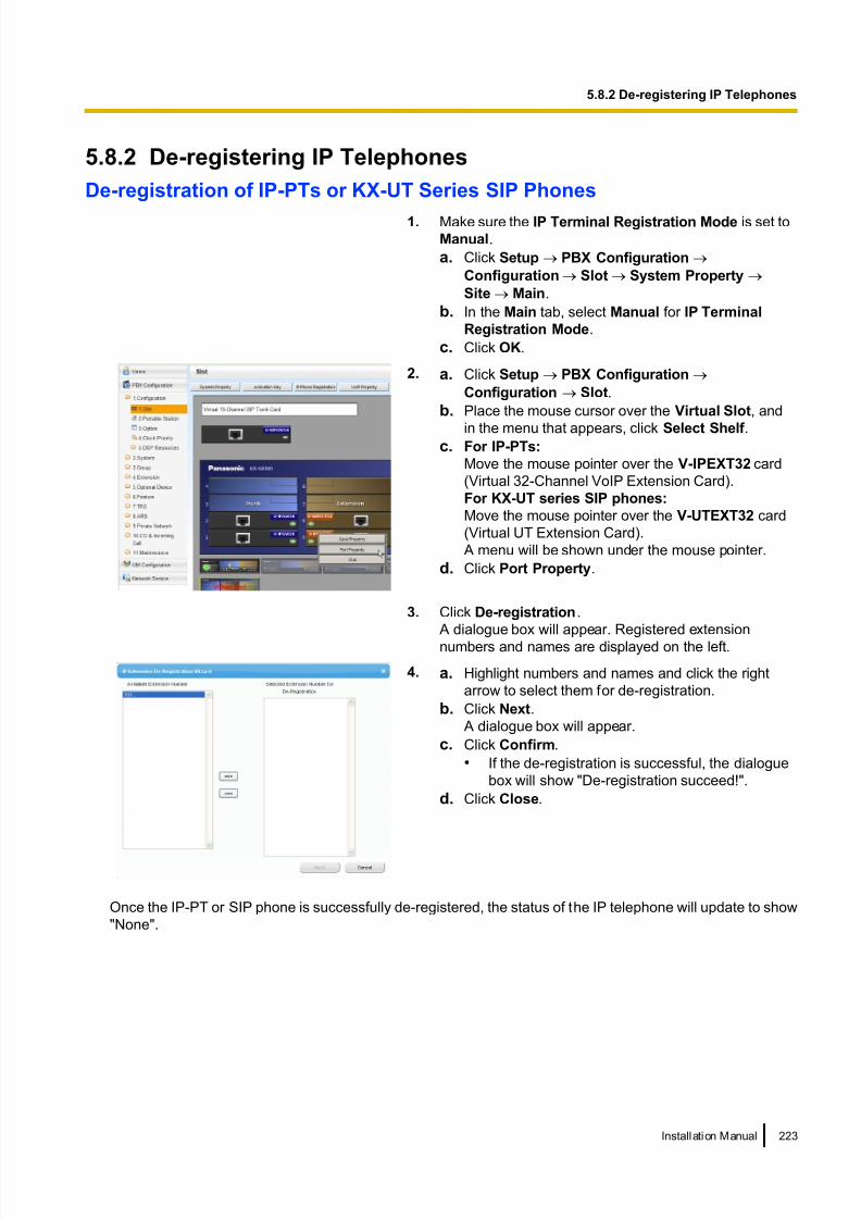
8/18/2019 NS500 Installation Manual
http://slidepdf.com/reader/full/ns500-installation-manual 223/300
5.8.2 De-registering IP Telephones
De-registration of IP-PTs or KX-UT Series SIP Phones
1. Make sure the IP Terminal Registration Mode is set to
Manual.
a. Click Setup ® PBX Configuration ®
Configuration ® Slot ® System Property ®
Site ® Main.
b. In the Main tab, select Manual for IP Terminal
Registration Mode.
c. Click OK.
2. a. Click Setup ® PBX Configuration ®
Configuration ® Slot.
b. Place the mouse cursor over the Virtual Slot, and
in the menu that appears, click Select Shelf .c. For IP-PTs:
Move the mouse pointer over the V-IPEXT32 card
(Virtual 32-Channel VoIP Extension Card).
For KX-UT series SIP phones:
Move the mouse pointer over the V-UTEXT32 card
(Virtual UT Extension Card).
A menu will be shown under the mouse pointer.
d. Click Port Property.
3. Click De-registration.
A dialogue box will appear. Registered extension
numbers and names are displayed on the left.
4. a. Highlight numbers and names and click the right
arrow to select them for de-registration.
b. Click Next.
A dialogue box will appear.
c. Click Confirm.
• If the de-registration is successful, the dialogue
box will show "De-registration succeed!".
d. Click Close.
Once the IP-PT or SIP phone is successfully de-registered, the status of the IP telephone will update to show
"None".
Installation Manual 223
5.8.2 De-registering IP Telephones

8/18/2019 NS500 Installation Manual
http://slidepdf.com/reader/full/ns500-installation-manual 224/300
Forced De-registration of IP-PTs or KX-UT Series SIP Phones
Follow the steps below to forcibly de-register an IP-PT when normal de-registration was unsuccessful.
1. a. Click Setup ®
PBX Configuration ®
Configuration ® Slot.
b. Place the mouse cursor over the Virtual Slot, and
in the menu that appears, click Select Shelf .
c. For IP-PTs:
Move the mouse pointer over the V-IPEXT32 card
(Virtual 32-Channel VoIP Extension Card).
For KX-UT series SIP phones:
Move the mouse pointer over the V-UTEXT32 card
(Virtual UT Extension Card).
A menu will be shown under the mouse pointer.
d. Click Port Property.
2. Click Forced De-registration.
A dialogue box will appear. Registered extension
numbers and names are displayed on the left.
3. a. Highlight numbers and names and click the right
arrow to select them for de-registration.
b. Click Next.
A dialogue box will appear.
c. Click OK.
A dialogue box will appear.
d. Click Confirm.
• If the de-registration is successful, the dialogue
box will show "Forced de-registration succeed!".
e. Click Close.
Once the IP-PT or SIP phone is successfully de-registered, the status of the IP telephone will update to show
"None".
224 Installation Manual
5.8.2 De-registering IP Telephones

8/18/2019 NS500 Installation Manual
http://slidepdf.com/reader/full/ns500-installation-manual 225/300
De-registration of Non-KX-UT Series SIP Phones
The de-registration of non-KX-UT series SIP phones is carried out by deleting either the extension number or
password registered in the PBX.
1. a. Click Setup ® PBX Configuration ®
Configuration ® Slot.
b. Place the mouse cursor over the Virtual Slot, and
in the menu that appears, click Select Shelf .
c. Move the mouse pointer over the V-SIPEXT32 card
(Virtual 32-Channel SIP Extension Card).
A menu will be shown under the mouse pointer.
d. Click Port Property.
2. a. Click the cell in the Connection column for the port
of the SIP phone to de-register.
b. In the Command window, click OUS to change the
status of the port to "OUS".
3. Repeat step 2 for each SIP phone to de-register.
4. Delete either the extension number or password for the
SIP phone to de-register, as shown here.
5. Click OK.
Installation Manual 225
5.8.2 De-registering IP Telephones

8/18/2019 NS500 Installation Manual
http://slidepdf.com/reader/full/ns500-installation-manual 226/300
5.8.3 Installing SIP Phones at a Remote Site
If an SBC (Session Border Controller) is present on the same local network as the KX-NS500, you can install
SIP phones at remote sites without needing to configure special network settings (NAT traversal, etc.).
This section provides information about the procedure for connecting SIP Phones at a remote site that has
SBC hardware.
When SIP phones in remote sites use the internet to communicate with the PBXs, use the HTTPS protocol for
security. If the connection is within a VPN and protected, you may use the HTTP protocol.
Main Site (Headquarters)
IP-PT SBC
Router
Switching Hub
KX-UT seriesSIP phone
Remote Site
Router
Main Unit*1 Switching Hub
Internet
: RTP packets*1 KX-NS500
Note
• Install the SBC in the same LAN as the KX-NS500.• A KX-NS500 can work with only one SBC. Also, multiple sites can share an SBC.
• A KX-NS500 can support up to 20 remote extensions at the same time via SBC when using the HTTPS
protocol.
• All the RTP packets in between the main site and the remote site is routed to the SBC for security and
for IP address conversion.
• When settings of remote extensions being used at remote sites are changed at the KX-NS500 at the
main site, the reflection of the changes to the remote extension may require some time due to data
transfer protocols.
Programming the KX-NS500
Follow the procedures below to configure remote port settings using Web Maintenance Console.
Note
For the procedures below, program WAN side IP information of the router at the main site.
This information is sent to KX-UT series SIP phones at the remote site after completing all programming.
For Site Property Settings
1. Click Setup ® PBX Configuration ® Configuration ® Slot.
2. Move the mouse pointer over System Property.
A menu will be shown under the mouse pointer.
3. Click Site.
4. Click the SIP Extension tab.
5. Click Advanced Setting for Remote SIP-MLT.Program the WAN side IP information in Setting parameters assigned to Remote SIP-MLT.
226 Installation Manual
5.8.3 Installing SIP Phones at a Remote Site

8/18/2019 NS500 Installation Manual
http://slidepdf.com/reader/full/ns500-installation-manual 227/300
a. Program the following common settings.
Configure the following items in Setting parameters assigned to Remote SIP-MLT.
WAN Side IP information of
the router at the main siteWeb Maintenance Console Parameter
CWMP
IP Address NAT - CWMP Server IP Address
SIP
IP Address NAT - SIP Proxy Server IP Address
Port Number NAT - SIP Proxy Server Port No.
NTP
IP Address NAT - NTP Server IP Address
Port Number NAT - NTP Server Port No.
b. Programme the following settings according to the protocol used by KX-UT series SIP phones in the
remote site.
When the KX-UT series SIP phones are using HTTPS
WAN Side IP information of
the router at the main site
Web Maintenance Console Parameter
CWMP
Port Number NAT - CWMP Server (HTTPS) Port No.
For Data Download
Port Number NAT - SIP-MLT Data Download Server (HTTPS) Port No.
When the KX-UT series SIP phones are using HTTPWAN Side IP information of
the router at the main siteWeb Maintenance Console Parameter
CWMP
Port Number NAT - CWMP Server (HTTP) Port No.
For Data Download
Port Number NAT - SIP-MLT Data Download Server (HTTP) Port No.
Installation Manual 227
5.8.3 Installing SIP Phones at a Remote Site

8/18/2019 NS500 Installation Manual
http://slidepdf.com/reader/full/ns500-installation-manual 228/300
6. Click OK.
7. Click Setup ® PBX Configuration ® Configuration ® Slot.
8. Move the mouse pointer over System Property.
A menu will be shown under the mouse pointer.9. Click Site.
10. Click Port Number tab.
11. Programme the following items according to the protocol used by KX-UT series SIP phones in the remote
site.
a. When the KX-UT series SIP phones are using HTTPS:
• CWMP (HTTPS) Port No. for SIP-MLT
• Data Transmission Protocol (HTTPS) Port No. for SIP-MLT
b. When the KX-UT series SIP phones are using HTTP:
• CWMP (HTTP) Port No. for SIP-MLT
• Data Transmission Protocol (HTTP) Port No. for SIP-MLT
NoteFor the default port numbers of the KX-NS500, refer to "8.5 Port Security".
12. Click OK.
13. Make a backup of the data that includes the above settings.
Click Setup ® System Control ® System Reset ® Backup.
Using a KX-NS500 as an NTP server
When the KX-NS500 will be used as a NTP server, follow the procedures below.
1. Click Setup ® Network Service ® Server Feature ® NTP.
2. Select Enable.
3. Click OK.
Programming the SBC
The following items need to be configured on the SBC. For information about configuring the SBC, refer to the
documentation of the SBC.
• IP address of the KX-NS500
• Port numbers of the KX-UT series SIP phones installed in the remote site
• IP address and subnet mask of the SBC
• LAN side IP address of the router at the main site
• WAN side IP address of the router at the main site
• SIP receiving port settings (For details, refer to the documentation of your SBC)
Note
For SIP receiving port of the SBC, specify the same port number that is specified at NAT - SIP Proxy
Server Port No. in step 5 in "Programming the KX-NS500" in this section.
• RTP Start Port (UDP) and RTP End Port (UDP)
Note
Make sure the RTP Start Port (UDP) and RTP End Port (UDP) specified for the SBC above are in the
range of the RTP port numbers that KX-NS500 uses.
For range of RTP port number of KX-NS500 , refer to "Port Numbers for Optional DSP Card" in "8.5 Port
Security".
• Firewall settings to allow SIP packets and RTP packets
228 Installation Manual
5.8.3 Installing SIP Phones at a Remote Site

8/18/2019 NS500 Installation Manual
http://slidepdf.com/reader/full/ns500-installation-manual 229/300
Programming the router at the main site
Port forwarding settings (Router – SBC)
Configure the following items for port forwarding in between the SBC and the router.
Application LAN Side Port Number WAN Side Port Number
SIP Proxy NAT-SIP Proxy Port No.
(Use the same value as NAT - SIP
Proxy Server Port No. in step 5 of
"Programming the KX-NS500".)
NAT-SIP Proxy Port No.
(Use the same value as NAT - SIP
Proxy Server Port No. in step 5 of
"Programming the KX-NS500".)
RTP (UDP) Start/End RTP (UDP) Port No.
(Use port numbers that are in the
range of the RTP ports that the
KX-NS500 uses.)
Start/End RTP (UDP) Port No.
(Use port numbers that are in the
range of the RTP ports that the
KX-NS500 uses.)
Make sure the RTP Start Port (UDP) and the RTP End Port (UDP) specifiedfor the router are in the range of the RTP ports that the KX-NS500 uses. For
the range of RTP port numbers that the KX-NS500 uses, refer to "Port
Numbers for Optional DSP Card" in "8.5 Port Security".
Note
For information about configur ing port forwarding on the router, refer to the documentation of the router.
Port forwarding settings (Router – KX-NS500)
Configure the following items for port forwarding between the KX-NS500 and the router.
Application LAN Side Port Number WAN Side Port Number
CWMP
HTTP CWMP (HTTP) Port No. for SIP-MLT
(Use the same value as in step 11 of
"Programming the KX-NS500".)
NAT - CWMP Server (HTTP) Port No.
(Use the same value as in step 5 of
"Programming the KX-NS500".)
HTTPS CWMP (HTTPS) Port No. for SIP-MLT
(Use the same value as in step 11 of
"Programming the KX-NS500".)
NAT - CWMP Server (HTTPS) Port No.
(Use the same value as in step 5 of
"Programming the KX-NS500".)
SIP-MLT Data
HTTP Data Transmission Protocol (HTTP)
Port No. for SIP-MLT
(Use the same value as in step 11 of
"Programming the KX-NS500".)
NAT - SIP-MLT Data Download Server
(HTTP) Port No.
(Use the same value as in step 5 of
"Programming the KX-NS500".)
HTTPS Data Transmission Protocol (HTTPS)
Port No. for SIP-MLT
(Use the same value as in step 11 of
"Programming the KX-NS500".)
NAT - SIP-MLT Data Download Server
(HTTPS) Port No.
(Use the same value as in step 5 of
"Programming the KX-NS500".)
Installation Manual 229
5.8.3 Installing SIP Phones at a Remote Site

8/18/2019 NS500 Installation Manual
http://slidepdf.com/reader/full/ns500-installation-manual 230/300
Application LAN Side Port Number WAN Side Port Number
NTP 123*1 NAT - NTP Server Port No.
(Use the same value as in step 5 of "Programming the KX-NS500".)
*1 The port number for NTP that the KX-NS500 uses is fixed to 123.
Note
For information about configuring port forwarding on the router, refer to the documentation of the router.
Installing KX-UT series SIP phones at a remote site
There are 2 methods to install KX-UT series SIP phones at a remote site:
• Set up KX-UT series SIP phones at the main site using the KX-NS500, and then send them to the remote
site.• Set up KX-UT series SIP phones without connecting them to the KX-NS500 at the main site, and then send
them to the remote site.
Setting up KX-UT series SIP phones at the main site, and then sending them to remote site
1. Register the KX-UT series SIP phone. For details, refer to "5.8.1 Registering IP Telephones".
2. Program the settings for the KX-UT series SIP phones.
a. Click Setup ® PBX Configuration ® Configuration ® Slot.
b. Place the mouse cursor over the Virtual Slot, and in the menu that appears, click Select Shelf .
c. Move the mouse pointer over the V-UTEXT32 card (Virtual UT Extension Card).
A menu will be shown under the mouse pointer.
d. Click Port Property.
e. Click Remote Place tab.f. Configure the items shown below.
• Select a protocol (HTTP/HTTPS) for Protocol for Remote SIP-MLT.
Note
When a SIP phone at remote site uses the internet to communicate with a KX-NS500 , use the
HTTPS protocol for security. If the connection is on VPN and protected, you may use the HTTP
protocol.
• Change the value to Remote (SBC) for Phone Location.
g. Click OK.
3. Unplug the AC adaptor of the KX-UT series SIP phone, and then plug it in again to reboot the KX-UT series
SIP phone manually.
The KX-UT series SIP phone will download settings automatically.
Note
• After downloading the setting information for the remote site, the KX-UT series SIP phone will not
connect to the KX-NS500 if it is connected to the LAN at the main site. After some time, the
KX-UT series SIP phone will display "9002: Connection Failed".
• Depending on the settings of your router, the KX-UT series SIP phone may connect to the PBX. In
such cases, proceed to step 4.
4. Send the KX-UT series SIP phone to the remote site and connect it to the LAN in the remote site.
Note
The KX-UT series SIP phone is already registered to the KX-NS500 and programmed with the remote
site configuration. There is no operation required for the KX-UT series SIP phone at the remote site.
230 Installation Manual
5.8.3 Installing SIP Phones at a Remote Site

8/18/2019 NS500 Installation Manual
http://slidepdf.com/reader/full/ns500-installation-manual 231/300
Setting up KX-UT series SIP phones without connecting to the KX-NS500 at the main site, andthen sending them to the remote site
1. Log in to the Web Maintenance Console of the site where the SIP phones will be registered.
2. Click Utility ® File ® File Transfer PBX to PC.
3. Select the config file according to the protocol used and then download it to your PC.
• HTTP is used
– UT_ACS_xxyyy.cfg
• HTTPS is used
– UT_ACS_HTTPS_xxyyyy.cfg
For more details about downloading files from a PBX to a PC, refer to "7.2.2 Utility—File—File Transfer
PBX to PC" in the PC Programming Manual.
Note
xx: Site ID (2 digits)yyyy: Site name*1 (Up to 32 characters*2)*1 Spaces as well as the following characters in site names will be replaced with underscores.
/, :, *, ?, ", <, >, | (vertical bar), &, +*2 In some cases, the full site name may not be included in the file name even if it is less than 32 characters.
4. Download the config file to the KX-UT series SIP phone via the Web user interface of the KX-UT series
SIP phone.
For details, refer to "When the SIP Phones are in a different LAN (Remote site installation)" in
"5.7.1 Assigning IP Addressing Information".
5. Connect the KX-UT series SIP phone to the LAN at the remote site.
6. Register the KX-UT series SIP phone to the KX-NS500 as a remote extension.
a. Click Setup ® PBX Configuration ® Configuration ® Slot.
b. Move the mouse pointer over the V-UTEXT32 card (Virtual UT Extension Card). A menu will be shown under the mouse pointer.
c. Click Port Property.
d. Click Remote Place tab.
e. Configure the items shown below.
• Change the value to Remote (SBC) for Phone Location.
• Change the value to Enable for Web-MC Ability.
• Select a protocol (HTTP/HTTPS) for Protocol for Remote SIP-MLT.
Note
Select the same value as you selected for NAT - SIP Proxy Server Port No. in step 5 of
"Programming the KX-NS500" in this section.
f. Click OK.
7. Register the KX-UT series SIP phone. For details, refer to "5.8.1 Registering IP Telephones".
Note
• You can select HTTPS for Protocol for Remote SIP-MLT only when Phone Location is set as
Remote (SBC).
• If the KX-UT series SIP phones don't work normally, confirm if the KX-UT series SIP phones are able
to access to internet.
Installation Manual 231
5.8.3 Installing SIP Phones at a Remote Site

8/18/2019 NS500 Installation Manual
http://slidepdf.com/reader/full/ns500-installation-manual 232/300

8/18/2019 NS500 Installation Manual
http://slidepdf.com/reader/full/ns500-installation-manual 233/300
5. Programme the WAN side information in Media Relay tab.
a. Programme the following common settings in Common.
WAN Side IP information of the router at
the main siteWeb Maintenance Console Parameter
IP Address NAT - External IP Address*1
*1 You can also programme individual items of the NAT - External IP Address. For more details, see step e.
b. Programme the following settings according to the protocol used by the KX-NT500 series IP extensions
in the remote site. Configure the following items in IP Extension.
WAN Side IP information of the router at the
main siteWeb Maintenance Console Parameter
MGCP
Port Number NAT - MGCP Server Port No.
c. Programme the following settings according to the protocol used by the KX-UT series IP extensions
and SIP extensions in the remote site. Configure the following items in SIP Extension / UT
Extension.
WAN Side IP information of the router at the
main siteWeb Maintenance Console Parameter
SIP
Port Number NAT - SIP Proxy Server Port No.
d. Programme the following settings according to the protocol used by the KX-UT series IP extensions in
the remote site. Configure the following items in UT Extension.
– When the KX-UT series SIP phones are using HTTPS:
WAN Side IP information of the router at the
main siteWeb Maintenance Console Parameter
CWMP
Port Number NAT - CWMP Server (HTTPS) Port No.
Port Number NAT - CWMP Server (HTTPS) Port No. for Network Survivability
For Data Download
Port Number NAT - SIP-MLT Data Download Server
(HTTPS) Port No.
– When the KX-UT series SIP phones are using HTTP:
WAN Side IP information of the router at the
main siteWeb Maintenance Console Parameter
CWMP
Installation Manual 233
5.8.4 Installing IP Phones at a Remote Site with a Built-in Media Relay Gateway

8/18/2019 NS500 Installation Manual
http://slidepdf.com/reader/full/ns500-installation-manual 234/300
WAN Side IP information of the router at the
main siteWeb Maintenance Console Parameter
Port Number NAT - CWMP Server (HTTP) Port No.
Port Number NAT - CWMP Server (HTTP) Port No. for
Network Survivability
For Data Download
Port Number NAT - SIP-MLT Data Download Server
(HTTP) Port No.
e. Programme the following common settings in Option.
WAN Side IP information of the router at themain site
Web Maintenance Console Parameter
RTP
IP Address NAT - RTP IP Address
SIP
IP Address NAT - SIP Proxy Server IP Address
CWMP
IP Address NAT - CWMP Server IP Address
IP Address NAT - CWMP Server IP Address for
Network Survivability
NTP
IP Address NAT - NTP Server IP Address
If necessary, you can program the individual settings here and overwrite the NAT - External IPAddress setting programmed in step a.
6. Click OK.
7. Click Setup ® PBX Configuration ® Configuration ® Slot.
8. Move the mouse pointer over System Property.
A menu will be shown under the mouse pointer.
9. Click Site.
10. Click the Port Number tab.
11. Programme the following items according to the protocol used by KX-UT series SIP phones in the remote
site.
a. When the KX-UT series SIP phones are using HTTPS:
• CWMP (HTTPS) Port No. for SIP-MLT
• Data Transmission Protocol (HTTPS) Port No. for SIP-MLT
234 Installation Manual
5.8.4 Installing IP Phones at a Remote Site with a Built-in Media Relay Gateway

8/18/2019 NS500 Installation Manual
http://slidepdf.com/reader/full/ns500-installation-manual 235/300
b. When the KX-UT series SIP phones are using HTTP:
• CWMP (HTTP) Port No. for SIP-MLT
• Data Transmission Protocol (HTTP) Port No. for SIP-MLT
Note
For the default port numbers of the KX-NS500, refer to "8.5 Port Security".
12. Click OK.
Using a KX-NS500 as an NTP server
When the KX-NS500 will be used as a NTP server, follow the procedures below.
1. Click Setup ® Network Service ® Server Feature ® NTP.
2. Select Enable.
3. Click OK.
Programming the router at the main site with Built-in Media Relay Gateway
Port forwarding settings (Router – KX-NS500)
Configure the following items for port forwarding between the Media Relay Gateway and the router.
For the KX-NT500 series:
Application LAN Side Port Number WAN Side Port Number
PTAP Signalling (PTAP) UDP Port No.
(Server)
(refer to PC Programming Guide
"9.15 PBX Configuration—[1-1]
Configuration—Slot—V-SIPEXT—Card Property")
Signalling (PTAP) UDP Port No.
(Server)
(refer to PC Programming Guide
"9.15 PBX Configuration—[1-1]
Configuration—Slot—V-SIPEXT—Card Property")
MGCP Signalling (MGCP) UDP Port No.
(Server)
(refer to PC Programming Guide
"9.15 PBX Configuration—[1-1]
Configuration—Slot—V-SIPEXT
—Card Property")
NAT - MGCP Server Port No.
(Use the same value as in step 5 of
"Programming the KX-NS500 with
Built-in Media Relay Gateway".)
RTP (UDP) Start/End RTP (UDP) Port No.
(Use port numbers that are in the
range of the RTP ports that the
KX-NS500 uses.)*1
Start/End RTP (UDP) Port No.
(Use port numbers that are in the
range of the RTP ports that the
KX-NS500 uses.)*1
Make sure the RTP Start Port (UDP) and the RTP End Port (UDP) specified
for the router are in the range of the RTP ports that the KX-NS500 uses. For
the range of RTP port numbers that the KX-NS500 uses, refer to "Port
Numbers for Optional DSP Card" in "8.5 Port Security".*1
*1 The port number ranges must be within the range of RTP/RTCP for NAT traversal (16000–17023).
Up to 2 IP addresses can be assigned to the KX-NS500’s optional DSP cards. The following example shows the port number ranges
set for each IP address:
[Example]
Port forward destination Port number range
DSP–1 16000–16511
Installation Manual 235
5.8.4 Installing IP Phones at a Remote Site with a Built-in Media Relay Gateway

8/18/2019 NS500 Installation Manual
http://slidepdf.com/reader/full/ns500-installation-manual 236/300
DSP–2 16512–17023
For the KX-UT series:
Application LAN Side Port Number WAN Side Port Number
SIP Proxy UDP Port No. for SIP Extension
Server
(refer to PC Programming Guide
"9.2.2 PBX Configuration—[1-1]
Configuration—Slot—System
Property—Site—Port Number")
NAT-SIP Proxy Port No.
(Use the same value as NAT - SIP
Proxy Server Port No. in step 5 of
"Programming the KX-NS500 with
Built-in Media Relay Gateway")
CWMP
HTTP CWMP (HTTP) Port No. for
SIP-MLT
(Use the same value as in step 11 of
"Programming the KX-NS500 with
Built-in Media Relay Gateway".)
NAT - CWMP Server (HTTP) Port
No.
(Use the same value as in step 5 of
"Programming the KX-NS500 with
Built-in Media Relay Gateway".)
HTTPS CWMP (HTTPS) Port No. for
SIP-MLT
(Use the same value as in step 11 of
"Programming the KX-NS500 with
Built-in Media Relay Gateway".)
NAT - CWMP Server (HTTPS) Port
No.
(Use the same value as in step 5 of
"Programming the KX-NS500 with
Built-in Media Relay Gateway".)
SIP-MLT Data
HTTP Data Transmission Protocol
(HTTP) Port No. for SIP-MLT
(Use the same value as in step 11 of
"Programming the KX-NS500 with
Built-in Media Relay Gateway".)
Data Transmission Protocol
(HTTP) Port No. for SIP-MLT
(Use the same value as in step 5 of
"Programming the KX-NS500 with
Built-in Media Relay Gateway".)
HTTPS Data Transmission Protocol
(HTTPS) Port No. for SIP-MLT
(Use the same value as in step 11 of
"Programming the KX-NS500 with
Built-in Media Relay Gateway".)
NAT - SIP-MLT Data Download
Server (HTTPS) Port No.
(Use the same value as in step 5 of
"Programming the KX-NS500 with
Built-in Media Relay Gateway".)
NTP 123*1 NAT - NTP Server Port No.
(Use the same value as in step 5 of
"Programming the KX-NS500 with
Built-in Media Relay Gateway".)
236 Installation Manual
5.8.4 Installing IP Phones at a Remote Site with a Built-in Media Relay Gateway

8/18/2019 NS500 Installation Manual
http://slidepdf.com/reader/full/ns500-installation-manual 237/300
Application LAN Side Port Number WAN Side Port Number
RTP (UDP) Start/End RTP (UDP) Port No.
(Use port numbers that are in therange of the RTP ports that the
KX-NS500 uses.)*2
Start/End RTP (UDP) Port No.
(Use port numbers that are in therange of the RTP ports that the
KX-NS500 uses.)*2
Make sure the RTP Start Port (UDP) and the RTP End Port (UDP) specified
for the router are in the range of the RTP ports that the KX-NS500 uses. For
the range of RTP port numbers that the KX-NS500 uses, refer to "Port
Numbers for Optional DSP Card" in "8.5 Port Security".*2
*1 The port number for NTP that the KX-NS500 uses is fixed to 123.*2 The port number ranges must be within the range of RTP/RTCP for NAT traversal (16000–17023).
Up to 2 IP addresses can be assigned to the KX-NS500’s optional DSP cards. The following example shows the port number ranges
set for each IP address:
[Example]
Port forward destination Port number range
DSP–1 16000–16511
DSP–2 16512–17023
Installing KX-NT500 series IP-PTs at a remote site with Built-in Media RelayGateway
You can install KX-NT500 series IP-PTs at the remote site directly or from the local site as follows.
1. Register the IP-PT. For details, refer to "5.8.1 Registering IP Telephones".
2. Programme the settings for the IP-PT.a. Click Setup ® PBX Configuration ® Configuration ® Slot.
b. Click Virtual ® V-IPEXT32.
c. Move the mouse pointer over the V-IPEXT32 card (Virtual IP Extension Card).
A menu will be shown under the mouse pointer.
d. Click Port Property.
e. Click the Remote Place tab.
f. Configure the items shown below.
• Change the value to Remote (MRG) for Phone Location.
g. Click OK.
3. Unplug the AC adaptor of the IP-PT, and then plug it in again to reboot the IP-PT manually. The IP-PT will
download settings automatically.
Installing KX-UT series SIP phones at a remote site with Built-in Media RelayGateway
There are 2 methods to install KX-UT series SIP phones at a remote site:
• Set up the phones at the main site using the KX-NS500, and then send them to the remote site.
• Set up the phones without connecting them to the KX-NS500 at the main site, and then send them to the
remote site.
Setting up KX-UT series SIP phones at the main site, and then sending them to remote site
1. Register the phone. For details, refer to "5.8.1 Registering IP Telephones".
2. Programme the settings for the phone.
a. Click Setup ® PBX Configuration ® Configuration ® Slot.
Installation Manual 237
5.8.4 Installing IP Phones at a Remote Site with a Built-in Media Relay Gateway

8/18/2019 NS500 Installation Manual
http://slidepdf.com/reader/full/ns500-installation-manual 238/300
b. Click Virtual ® V-UTEXT32.
c. Move the mouse pointer over the V-UTEXT32 card (Virtual UT Extension Card).
A menu will be shown under the mouse pointer.
d. Click Port Property.e. Click the Remote Place tab.
f. Configure the items shown below.
• Change the value to Remote (MRG) for Phone Location.
• Select a protocol (HTTP/HTTPS) for Protocol for Remote SIP-MLT.
Note
When a SIP phone at a remote site uses the internet to communicate with a KX-NS500, use
the HTTPS protocol for security. If the connection is on a VPN and is protected, you may use
the HTTP protocol.
g. Click OK.
3. Unplug the AC adaptor of the phone, and then plug it in again to reboot the phone manually. The phone
will download settings automatically.
Note
• After downloading the setting information for the remote site, the KX-UT series SIP phone will not
connect to the KX-NS500 if it is connected to the LAN at the main site. After some time, the
KX-UT series SIP phone will display "9002: Connection Failed".
• Depending on the settings of your router, the KX-UT series SIP phone may connect to the PBX. In
this case, proceed to step 4.
4. Send the KX-UT series SIP phone to the remote site and connect it to the LAN in the remote site.
Note
The KX-UT series SIP phone is already registered to the KX-NS500 and programmed with the remote
site configuration. No operation is required for the KX-UT series SIP phone in the remote site.
Setting up KX-UT series SIP phones without connecting to the KX-NS500 at the main site, andthen sending them to the remote site
1. Log in to Web Maintenance Console of the site where the SIP phones will be registered.
2. Click Utility ® File ® File Transfer PBX to PC.
3. Select the config file according to the protocol used and then download it to your PC.
• If HTTPS is used:
– UT_MRG_HTTPS_xxyyyy.cfg
For more details about downloading files from a PBX to a PC, refer to "7.2.2 Utility—File—File Transfer
PBX to PC" in the PC Programming Manual.
Notexx: Site ID (2 digits)
yyyy: Site name*1 (Up to 32 characters*2)*1 Spaces as well as the following characters in site names will be replaced with underscores.
/, :, *, ?, ", <, >, | (vertical bar), &, +*2 In some cases, the full site name may not be included in the file name even if it is less than 32 characters.
4. Download the config file to the KX-UT series SIP phone via the Web user interface of the KX-UT series
SIP phone. For details, refer to "When the SIP Phones are in a different LAN (Remote site installation)" in
"5.7.1 Assigning IP Addressing Information".
5. Connect the KX-UT series SIP phone to the LAN in the remote site.
6. Register the KX-UT series SIP phone to the KX-NS500 as a remote extension.
a. Click Setup ®
PBX Configuration ®
Configuration ®
Slot.b. Click Virtual ® V-UTEXT32.
238 Installation Manual
5.8.4 Installing IP Phones at a Remote Site with a Built-in Media Relay Gateway

8/18/2019 NS500 Installation Manual
http://slidepdf.com/reader/full/ns500-installation-manual 239/300
c. Move the mouse pointer over the V-UTEXT32 card (Virtual UT Extension Card).
A menu will be shown under the mouse pointer.
d. Click Port Property.
e. Click the Remote Place tab.f. Configure the items shown below.
• Change the value Remote (MRG) to for Phone Location.
• Change the value Enable for Web-MC Ability.
• Select a protocol (HTTP/HTTPS) for Protocol for Remote SIP-MLT.
Note
Select the same value as you selected for NAT - SIP Proxy Server Port No. in step 5 of
"Programming the KX-NS500 with Built-in Media Relay Gateway" in this section.
g. Click OK.
7. Register the KX-UT series SIP phone. For details, refer to "5.8.1 Registering IP Telephones".
Note• You can select HTTPS for Protocol for Remote SIP-MLT only when Phone Location is set as
Remote (MRG).
• If the KX-UT series SIP phone does not work normally, confirm whether the KX-UT series SIP
phone can access the internet.
Installation Manual 239
5.8.4 Installing IP Phones at a Remote Site with a Built-in Media Relay Gateway

8/18/2019 NS500 Installation Manual
http://slidepdf.com/reader/full/ns500-installation-manual 240/300
5.9 Configuration of UsersThe system manages information about each user.
Before programming other user settings, the following information must be configured for each user:• Extension number
• Name
• Unified Messaging mailbox
• Web Maintenance Console login account (ID and password)
Follow the procedure below to efficiently programme basic personal information by adding multiple users with
the Add Range feature.
1. Click Setup ® PBX Configuration ® Configuration ® Slot.
Add one or more extension cards to the system, according to your equipment and needs. Extension
numbers will be automatically created for each extension card that is added. For details about adding
extension cards, refer to "9.1 PBX Configuration—[1-1] Configuration—Slot" in the PC Programming
Manual.
2. Click Setup ® PBX Configuration ® Extension.Enter an extension name for each extension number to be used. For details, refer to the following sections
in the PC Programming Manual:
• 12.1.1 PBX Configuration—[4-1-1] Extension—Wired Extension—Extension Settings
• 12.2.1 PBX Configuration—[4-2-1] Extension—Portable Station—Extension Settings
Note
You also can import extension names from a CSV file. For details refer to "6.5 Tool—Import" in the
PC Programming Manual.
3. Click Setup ® Users ® User Profiles.
Select Rule of copy to extension name on the Option tab.
• Rule-A: [First Name] [space] [Last Name]
• Rule-B: [Last Name] [,] [First Name]4. Click Setup ® Users ® User Profiles.
You can create multiple user profiles automatically by using the Add Range feature for extension numbers.
You can also set an extension number, first name, last name, Unified Messaging mailbox, and Web
Maintenance Console login account for each user manually.
For details, refer to "User Controls" in "8.1 Users—User Profiles" in the PC Programming Manual.
For each user profile added using the Add Range feature, the following information is automatically
assigned:
• First Name/Last Name
Extension Name, which is the name displayed on extension LCDs, can be copied a ll at once to the
First Name and Last Name settings for each extension.
The format you selected in Rule of copy to extension name in step 3 determines how these are
copied. – Case 1: You selected Rule-A, and the format of the name is assumed to be "[First Name] (space)
[Last Name]".
– Case 2: You selected Rule-B, and the format of the name is assumed to be "[ Last Name], [First
Name]".
– Case 3: Extension Name is set to not follow Rule of copy to extension name:
Example of copying Extension Name
Extension Name
User Profile
First Name Last Name
Case 1 Tarou Yamada Tarou Yamada
240 Installation Manual
5.9 Configuration of Users
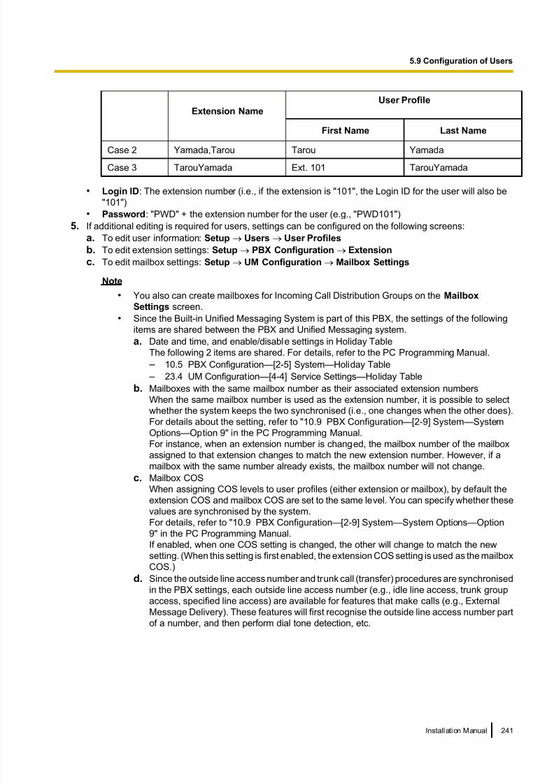
8/18/2019 NS500 Installation Manual
http://slidepdf.com/reader/full/ns500-installation-manual 241/300
Extension Name
User Profile
First Name Last Name
Case 2 Yamada,Tarou Tarou Yamada
Case 3 TarouYamada Ext. 101 TarouYamada
• Login ID: The extension number (i.e., if the extension is "101", the Login ID for the user will also be
"101")
• Password: "PWD" + the extension number for the user (e.g., "PWD101")
5. If additional editing is required for users, settings can be configured on the following screens:
a. To edit user information: Setup ® Users ® User Profiles
b. To edit extension settings: Setup ® PBX Configuration ® Extension
c. To edit mailbox settings: Setup ® UM Configuration ® Mailbox Settings
Note
• You also can create mailboxes for Incoming Call Distribution Groups on the Mailbox
Settings screen.
• Since the Built-in Unified Messaging System is part of this PBX, the settings of the following
items are shared between the PBX and Unified Messaging system.
a. Date and time, and enable/disable settings in Holiday Table
The following 2 items are shared. For details, refer to the PC Programming Manual.
– 10.5 PBX Configuration—[2-5] System—Holiday Table
– 23.4 UM Configuration—[4-4] Service Settings—Holiday Table
b. Mailboxes with the same mailbox number as their associated extension numbers
When the same mailbox number is used as the extension number, it is possible to select
whether the system keeps the two synchronised (i.e., one changes when the other does).For details about the setting, refer to "10.9 PBX Configuration—[2-9] System—System
Options—Option 9" in the PC Programming Manual.
For instance, when an extension number is changed, the mailbox number of the mailbox
assigned to that extension changes to match the new extension number. However, if a
mailbox with the same number already exists, the mailbox number will not change.
c. Mailbox COS
When assigning COS levels to user profiles (either extension or mailbox), by def ault the
extension COS and mailbox COS are set to the same level. You can specify whether these
values are synchronised by the system.
For details, refer to "10.9 PBX Configuration—[2-9] System—System Options—Option
9" in the PC Programming Manual.
If enabled, when one COS setting is changed, the other will change to match the newsetting. (When this setting is first enabled, the extension COS setting is used as the mailbox
COS.)
d. Since the outside line access number and trunk call (transfer) procedures are synchronised
in the PBX settings, each outside line access number (e.g., idle line access, trunk group
access, specified line access) are available for features that make calls (e.g., External
Message Delivery). These features will first recognise the outside line access number part
of a number, and then perform dial tone detection, etc.
Installation Manual 241
5.9 Configuration of Users

8/18/2019 NS500 Installation Manual
http://slidepdf.com/reader/full/ns500-installation-manual 242/300
5.10 Programming E-mail Integration for UM VoiceUsers with Unified Messaging (UM) mailboxes (referred to below as "subscribers") can receive their voice as
data using the following methods: – Receiving attachments to a POP3 e-mail account
– Accessing data through an IMAP4 e-mail account
Note
KX-NSU201, KX-NSU205, KX-NSU210, KX-NSU220, or KX-NSU299 (Activation Key for Unified
Messaging E-mail Notification) is required to enable this feature for users.
For details about these activation keys, see "Unified Messaging System (Mailbox)" in "3.1.1 Type and
Maximum Number of Activation Keys".
Receiving Attachments to a POP3 E-mail Account
An e-mail can be sent to Unified Message system subscribers, notifying them of a new voice. Subscribers canalso choose to have the voice message attached to the notification, as well as choose to have the message
deleted from the system after it has been sent.
1. Specify SMTP server settings.
a. Click Setup Network Service ® Server Feature ® SMTP.
b. Specify the name to be used for the e-mail messages that will be sent from the system in Mail
sending—Mail sender infor mation name.
c. Specify the e-mail address for the e-mail messages that will be sent from the system in Mail
sending—Mail Address.
d. Specify the IP address or host name of the SMTP server to use in SMTP server for relay—SMTP
server address.
e. Specify the port number of the SMTP server to use in SMTP server for relay—SMTP server Port
number .f. Specify the following parameters if required.
– SMTP over TLS
– SMTP Authentication
– POP before SMTP
– Receive Port number (SMTP)
– Receive Port number (SMTPs)
Note
For details about these parameters, refer to "27.2.5 Network Service—[2-6] Server
Feature—SMTP" in the PC Programming Manual.
g. Click OK.
2. Specify e-mail options.
a. Click Setup ® UM Configuration ® System Parameters ® Parameters ® E-mail Option.
b. Specify the following parameters.
– Mail Address (Up to 128 ASCII characters)
– Full Name (Up to 64 ASCII characters)
– Maximum Message Length (Selection)
– Maximum Message Length (Other) (1-30 min)
c. Click OK.
3. Enable e-mail notification.
a. Click Setup ® UM Configuration ® Class of Service ® General.
b. In E-mail Option, select Yes for all Class of Service members that will receive e-mail notifications.
c. Click OK.
242 Installation Manual
5.10 Programming E-mail Integration for UM Voice
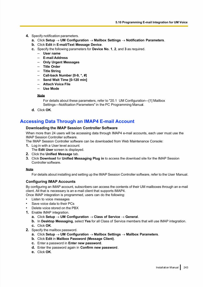
8/18/2019 NS500 Installation Manual
http://slidepdf.com/reader/full/ns500-installation-manual 243/300
4. Specify notification parameters.
a. Click Setup ® UM Configuration ® Mailbox Settings ® Notification Parameters.
b. Click Edit in E-mail/Text Message Device.
c. Specify the following parameters for Device No. 1, 2, and 3 as required. – User name
– E-mail Address
– Only Urgent Messages
– Title Order
– Title String
– Call-back Number [0-9, *, #]
– Send Wait Time [0-120 min]
– Attach Voice File
– Use Mode
Note
For details about these parameters, refer to "20.1 UM Configuration—[1] MailboxSettings—Notification Parameters" in the PC Programming Manual.
d. Click OK.
Accessing Data Through an IMAP4 E-mail Account
Downloading the IMAP Session Controller Software
When more than 24 users will be accessing data through IMAP4 e-mail accounts, each user must use the
IMAP Session Controller software.
The IMAP Session Controller software can be downloaded from Web Maintenance Console:
1. Log in with a User level account.
The Edit User screen is displayed.2. Click the Unified Message tab.
3. Click Download for Unified Messaging Plug in to access the download site for the IMAP Session
Controller software.
Note
For details about installing and setting up the IMAP Session Controller software, refer to the User Manual.
Configuring IMAP Accounts
By configuring an IMAP account, subscribers can access the contents of their UM mailboxes through an e-mail
client. All that is necessary is an e-mail client that supports IMAP4.
Once IMAP integration is programmed, users can do the following:
• Listen to voice messages
• Save voice data to their PCs
• Delete voice stored on the PBX
1. Enable IMAP integration.
a. Click Setup ® UM Configuration ® Class of Service ® General.
b. In Desktop Messaging, select Yes for all Class of Service members that will use IMAP integration.
c. Click OK.
2. Specify the mailbox password.
a. Click Setup ® UM Configuration ® Mailbox Settings ® Mailbox Parameters.
b. Click Edit in Mailbox Password (Message Client).
c. Enter a password in Enter new password.
d. Enter the password again in Confirm new password.
e. Click OK.
Installation Manual 243
5.10 Programming E-mail Integration for UM Voice

8/18/2019 NS500 Installation Manual
http://slidepdf.com/reader/full/ns500-installation-manual 244/300
f. Click OK.
3. Specify IMAP parameters.
a. Click Setup Network Service ® Server Feature ® IMAP4.
b. Specify the following parameters (if required). – IMAP4 server
– Port Number
– IMAP4 over SSL
– CAPABILITY command
– Authenticated Connection Timeout
Note
For details about these parameters, refer to "27.2.6 Network Service—[2-7] Server
Feature—IMAP4" in the PC Programming Manual.
c. Click OK.
Setting Up the IMAP Account in a Subscriber’s E-mail Client An account must be set up in each subscriber’s e-mail client for use with the Unified Messaging system. The
setup procedure will vary depending on the e-mail client application used and the configuration of your network.
When adding the account, the settings must be specified as follows:
– The e-mail address will be the subscriber’s existing e-mail address.
– The type of the account must be set to "IMAP".
– The incoming mail server must be set as the IP Address of the PBX where the subscriber’s UM mailbox is
located.
– The user name/ID will be the subscriber’s UM Mailbox Number.
– The password will be the Mailbox Password (Message Client) set in step 2 above.
– A valid SMTP server must be used (i.e. the SMTP server used for existing mail accounts).
The following example setup procedure is for Microsoft Outlook® 2010. Subscribers’ e-mail client setting names
and locations may differ.1. In Outlook 2010, select File, and then Info.
2. Click the Add Account button.
3. Select Manually configure server settings or additional server types.
4. Select Internet E-mail, and then click Next.
5. Configure the server settings as follows:
User Information
– In Your Name, enter the name of the subscriber. (In the example, "John Smith")
– In E-mail Address, enter the existing mail address of the subscriber. (In the example below,
Server Information – Select IMAP for Account type.
– In Incoming mail server , enter the IP address of the PBX where the subscriber’s UM mailbox is
located. (In the example below, "10.178.19.206")
– In Outgoing mail server (SMTP), enter the SMTP server used for the subscriber’s existing mail
account. (In the example below, "mail.example.com")
Logon Information
– In User Name, enter the subscriber’s Mailbox Number. (In the example below, "407")
– In Password, enter the password for the subscriber specified in Mailbox Password (Message Client).
6. Click Next and then complete the account settings.
244 Installation Manual
5.10 Programming E-mail Integration for UM Voice

8/18/2019 NS500 Installation Manual
http://slidepdf.com/reader/full/ns500-installation-manual 245/300
Example IMAP Account Settings (Outlook 2010)
Installation Manual 245
5.10 Programming E-mail Integration for UM Voice
8/18/2019 NS500 Installation Manual
http://slidepdf.com/reader/full/ns500-installation-manual 246/300
5.11 Automatic Configuration of MailboxesMailboxes can be automatically created and associated with an extension number if these items do not already
exist. There are 2 modes for creating mailboxes. For each specified extension number, a mailbox isautomatically created if one is not already associated with the extension. The results of creating and associating
mailboxes and user profiles with extension numbers are output both to a file and to the syslog. If many
mailboxes must be created or deleted, the amount of time required to complete the task is displayed on the
screen.
Creating mailboxes for all extensions
Note
If a mailbox does not satisfy the conditions for automatic creation, neither will be created for the
corresponding extension.
1. In Web Maintenance Console, click Setup-UM Configuration-Mailbox Settings-Auto Configuration-Create
all mailboxes
2. Click Execute.
• Mailboxes are created with the same number as the extension number.
• However, a mailbox will not be created in any of the following conditions:
a. A mailbox with the same number as the extension number already exists
b. The extension number has only 1 digit
c. The total number of mailboxes, including already existing mailboxes, exceeds 500
Re-creating all mailboxes
IMPORTANT
This procedure deletes all existing voice data, all settings and all prompts from all mailboxes. Inthis procedure, voice data (e.g., mailbox voice data, personal greetings) and settings (e.g., the password)
are not deleted from the managers' mailboxes. Be sure to make a backup of any important data beforehand.
If mailbox numbers are changed after mailboxes have been deleted using this feature, even if a backup of
the mailbox settings, voice data (e.g., personal greetings), and messages has been made, the data cannot
be restored. After executing this function, all messages will have been deleted, and it is necessary to
reconfigure all mailbox settings and re-record all prompts.
1. In Web Maintenance Console, click Setup®UM Configuration®Mailbox Settings® Auto
Configuration®Re-create all mailboxes
2. Select the radio button where you want the mailboxes to be created.
– Create mailboxes to the UM group of the PBX where the extensions belong to
– Create mailboxes to the specified UM group (UM Group No. 1 to 16)
3. Click Execute.
• Every type of mailbox, except the manager's mailboxes, will be deleted.
• If there are currently mailboxes in use, you can select whether to delete them forcibly or cancel the
operation.
• All mailboxes will be recreated.
• A mailbox will not be created in the following conditions:
– The extension number has only 1 digit
Results of creating mailboxes
The results of creating mailboxes are recorded in a text file. Follow the procedure below to view the file.
1. When automatic configuration completes, click OK on the "Mailbox create result" dialogue box.
246 Installation Manual
5.11 Automatic Configuration of Mailboxes

8/18/2019 NS500 Installation Manual
http://slidepdf.com/reader/full/ns500-installation-manual 247/300
2. Mailbox_result.txt is saved to the local PC.
3. The meaning of the status in the generated file is as follows:
User Profile Status Description
Exist The user profile already existed and was assigned to the related mailbox and
extension number.
Skipped The user profile was already assigned to the related mailbox and extension
number.
Mailbox Status Description
Created The new mailbox was successfully created.
Failed The new mailbox was not created.
Assigned The mailbox already existed, but was successfully assigned to the related
extension number.
Exist The mailbox was already assigned to the related extension number.
Skipped The mailbox already existed, but assigning it to the related extension number
failed.
The start and finish times of the automatic configuration is recorded in the syslog (INFO). For details, refer
to "7.3.2 Utility—Log—Syslog" in the PC Programming Manual.
Installation Manual 247
5.11 Automatic Configuration of Mailboxes

8/18/2019 NS500 Installation Manual
http://slidepdf.com/reader/full/ns500-installation-manual 248/300
248 Installation Manual
5.11 Automatic Configuration of Mailboxes

8/18/2019 NS500 Installation Manual
http://slidepdf.com/reader/full/ns500-installation-manual 249/300
Section 6
Methods of Stacking Expansion Units
This section provides information about stacking
expansion units.
Installation Manual 249

8/18/2019 NS500 Installation Manual
http://slidepdf.com/reader/full/ns500-installation-manual 250/300
6.1 Methods of Stacking Expansion UnitsStacking expansion units with the KX-NS500 allows you to expand the usage of legacy terminals and trunks.
When expansion units are stacked, the KX-NS500 will control communication, as well as all IP terminals onthe site.
Note
For details about connecting an expansion unit to a KX-NS500, refer to the 4.6.1 EXP-M Card
(KX-NS5130) in this manual.
There are 2 ways of stacking Expansion Units with the KX-NS500.
Case 1
Stacking expansion units to a KX-NS500 (not running).
To stack expansion units to a KX-NS500 which is not running currently, refer to "Procedure for Case 1 and
Case 2".
Case 2
Stacking expansion units to a KX-NS500 (running).
To stack expansion units to a KX-NS500 which is already running, refer to "Procedure for Case 1 and Case
2".
Stacking Procedures
The following procedures show how to stack expansion units in each case.
CAUTION
• When installing or removing the optional service cards, the power switch must be turned off.
• When installing or removing the optional service cards, do not put pressure on any parts of the mother board. Doing so may result in damage to the PBX.
Notice
If there is already a expansion unit stacked and connected to a EXP-M card installed in a KX-NS500, you
can skip shutting down the KX-NS500 in the following procedures.
Note
• For information about starting the KX-NS500 for the first time, refer to "4.13 Starting the KX-NS500".
• The Expansion Unit will be initialised when started up with a EXP-M card mounted and extension
numbers will be created automatically.
Procedure for Case 1 and Case 2
1. Follow the procedure below for the expansion unit.
a. Make sure the power switch is turned off. If the KX-NS500 is running, shutdown the KX-NS500 and
then turn off the power switch.
b. Connect the LAN cable to EXP-S card.
2. Follow the pr ocedure below for the KX-NS500.
a. Make sure the power switch is turned off.
b. Insert a EXP-M card into the EXP-M card slot.
c. Connect the LAN cable to EXP-M card.
3. Follow the procedure below for the KX-NS500 and expansion unit KX-NS520.
a. Turn the power switch on.
250 Installation Manual
6.1 Methods of Stacking Expansion Units

8/18/2019 NS500 Installation Manual
http://slidepdf.com/reader/full/ns500-installation-manual 251/300
Pre-installing stacked Expansion units connected to the EXP-M card
Once a EXP-M card has been added to the physical shelf on the Slot screen, you can pre-install stacked
Expansion units connected to the EXP-M card.
1. Log in to Web Maintenance Console. For details, refer to "Connecting to Web Maintenance Console" in"5.3 Starting Web Maintenance Console".
2. Click Setup ® PBX Configuration ® Configuration ® Slot.
3. Place the mouse cursor over the EXP-M card, and in the menu that appears, click Pre-Install.
4. Select the Expansion unit connected to connection port 1 of the EXP-M card, and then click the arrow
button.
5. If a second stackable Expansion units is connected to connection port 2 of the EXP-M card, click the arrow
button.
6. Click OK when finished to complete pre-installation.
Programming Expansion unit
To programme Expansion units that are stacked with a KX-NS500, use Web Maintenance Console.
To log in to Web Maintenance Console, refer to "Connecting to Web Maintenance Console" in "5.3 Starting
Web Maintenance Console".
For more information about programming Expansion unit, refer to the PC Programming Manual.
Installation Manual 251
6.1 Methods of Stacking Expansion Units

8/18/2019 NS500 Installation Manual
http://slidepdf.com/reader/full/ns500-installation-manual 252/300
252 Installation Manual
6.1 Methods of Stacking Expansion Units

8/18/2019 NS500 Installation Manual
http://slidepdf.com/reader/full/ns500-installation-manual 253/300
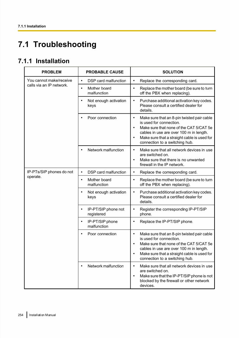
8/18/2019 NS500 Installation Manual
http://slidepdf.com/reader/full/ns500-installation-manual 254/300
7.1 Troubleshooting
7.1.1 Installation
PROBLEM PROBABLE CAUSE SOLUTION
You cannot make/receive
calls via an IP network.• DSP card malfunction • Replace the corresponding card.
• Mother board
malfunction
• Replace the mother board (be sure to turn
off the PBX when replacing).
• Not enough activation
keys
• Purchase additional activation key codes.
Please consult a certified dealer for
details.
• Poor connection • Make sure that an 8-pin twisted pair cableis used for connection.
• Make sure that none of the CAT 5/CAT 5e
cables in use are over 100 m in length.
• Make sure that a straight cable is used for
connection to a switching hub.
• Network malfunction • Make sure that all network devices in use
are switched on.
• Make sure that there is no unwanted
firewall in the IP network.
IP-PTs/SIP phones do not
operate.
• DSP card malfunction • Replace the corresponding card.
• Mother board
malfunction
• Replace the mother board (be sure to turn
off the PBX when replacing).
• Not enough activation
keys
• Purchase additional activation key codes.
Please consult a certified dealer for
details.
• IP-PT/SIP phone not
registered
• Register the corresponding IP-PT/SIP
phone.
• IP-PT/SIP phone
malfunction
• Replace the IP-PT/SIP phone.
• Poor connection • Make sure that an 8-pin twisted pair cable
is used for connection.
• Make sure that none of the CAT 5/CAT 5e
cables in use are over 100 m in length.
• Make sure that a straight cable is used for
connection to a switching hub.
• Network malfunction • Make sure that all network devices in use
are switched on.
• Make sure that the IP-PT/SIP phone is not
blocked by the firewall or other network
devices.
254 Installation Manual
7.1.1 Installation

8/18/2019 NS500 Installation Manual
http://slidepdf.com/reader/full/ns500-installation-manual 255/300
PROBLEM PROBABLE CAUSE SOLUTION
Extensions (except IP-PT/
SIP phone) do not operate.
• Extension card
malfunction
• Replace the corresponding card.
• Poor connection
between the PBX and
the extension
• Take the extension and plug it into the
same extension port using a short
telephone cord. If the extension works,
then the connection between the PBX and
the extension must be repaired.
• A telephone with an
A-A1 relay is
connected.
• Make sure that a 2-wire cord is used.
• Make sure that the A-A1 relay switch of
the telephone is in "OUT" or "OFF"
position.
• Extension malfunction • Take the extension and plug it into
another extension port that is working. If
the extension does not work, replace the
extension.
The PBX does not operate
properly.
• Restart the PBX (refer to
"7.1.5 Restarting the KX-NS500").
• Turn off the power switch, and then turn it
back on.
• Turn off the power switch, and then
unplug the PBX. After 5 minutes, plug the
PBX back in, and turn the power switch
back on.
Noise on external paging. • Induced noise on thewire between the PBX
and the amplifier.
• Use a shielded cable as the connectionwire between the PBX and amplifier. A
short shielded cable is recommended.
Distorted external music. • Excessive input level
from external music
source.
• Decrease the output level of the external
music source by using the volume control
on the music source.
The STATUS indicator on
the front of the cabinet turns
on red.
• A major system error
occurs in the PBX.
• See the error log using Web Maintenance
Console (refer to "7.1.6 Troubleshooting
by Error Log").
The LINK indicator of the
mother board does not turnon.
• Mother board
malfunction
• Replace the mother board (be sure to turn
off the PBX when replacing).• Poor connection. • Make sure that an 8-pin twisted pair cable
is used for connection.
• Make sure that none of the CAT 5/CAT 5e
cables in use are over 100 m in length.
• Make sure that a straight cable is used for
connection to a switching hub.
• Network malfunction • Make sure that all network devices in use
are switched on.
Installation Manual 255
7.1.1 Installation

8/18/2019 NS500 Installation Manual
http://slidepdf.com/reader/full/ns500-installation-manual 256/300
PROBLEM PROBABLE CAUSE SOLUTION
The LED of the Expansion
Unit card is not green.
The LAN cable is not
connected properly.
• Check the LAN cable connections.
There was a failure in the
stacking card.• Replace the stacking EXP-M card.
256 Installation Manual
7.1.1 Installation
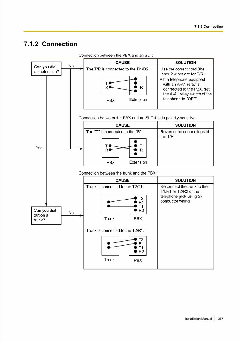
8/18/2019 NS500 Installation Manual
http://slidepdf.com/reader/full/ns500-installation-manual 257/300
7.1.2 Connection
Connection between the trunk and the PBX:
CAUSE
Trunk is connected to the T2/T1.
SOLUTION
Reconnect the trunk to the
T1/R1 or T2/R2 of the
telephone jack using 2-
conductor wiring.T2R1T1R2
Trunk PBX
Trunk is connected to the T2/R1.
PBXTrunk
T2R1T1R2
NoCan you dial
out on a
trunk?
NoCan you dial
an extension?
Connection between the PBX and an SLT that is polarity-sensitive:
PBX
CAUSE
The "T" is connected to the "R".
SOLUTION
TR
TR
Extension
Reverse the connections of
the T/R.
Yes
Connection between the PBX and an SLT:
CAUSE SOLUTION
If a telephone equipped
with an A-A1 relay is
connected to the PBX, set
the A-A1 relay switch of the
telephone to "OFF".
Use the correct cord (the
inner 2 wires are for T/R).
PBX
The T/R is connected to the D1/D2.
TR
TR
Extension
Installation Manual 257
7.1.2 Connection

8/18/2019 NS500 Installation Manual
http://slidepdf.com/reader/full/ns500-installation-manual 258/300
7.1.3 Operation
Note
For devices connected to a PBX other than the KX-NS500, refer to the Troubleshooting for that PBX.
PROBLEM PROBABLE CAUSE SOLUTION
• Cannot set the IP
address, subnet mask
address, and PBX IP
address to the IP-PT.
• An unusable value is
being set.
• Set an IP address within the valid range.
IP address of the IP-PT/PBX: "1.0.0.0" to
"223.255.255.255" Subnet mask address:
"0–255.0–255.0–255.0–255" (except
"0.0.0.0" and "255.255.255.255")
• Cannot register the
IP-PT.
• The necessary network
parameters are not set
to the IP-PT.
• When not using the DHCP Server feature
or an external DHCP server, set the IP
address, subnet mask address, and enter
the PBX IP address. If necessary, also
enter the IP address of the default
gateway.
• When using the DHCP Server feature or
an external DHCP server, enter the PBX
IP address.
• The IP-PT cannot
connect to the PBX.
• The wrong IP address,
subnet mask address,
PBX IP address, or
default gateway
address was entered.
• Check each parameter and enter the
correct value.
• The Ethernet cable is
not connected
correctly.
• Check the Ethernet cable connections.
• The DHCP server is not
active.
• Restart the external DHCP server.
• Confirm whether the DHCP Server feature
is enabled.
• Disable DHCP and re-enter settings as
appropriate.
• Whenever you try to
make calls using a SIP
phone, a busy tone is
heard.
• The status of the port
that the SIP phone is
connected to is Out of
Service.
• Change the port status from Out of
Service to In Service using Web
Maintenance Console.
• The IP-PT does not
ring.
• The ringer volume is off. • Turn on the ringer volume.
• Originating an outside
call, call transfer, or
conference cannot be
performed.
• The corresponding
flexible button does not
exist on the PT.
• Programme the flexible button. Refer to
"2.21.1 Fixed Buttons" in the Feature
Guide.
• The IP address of the
PBX for networking has
been forgotten.
- • You can check the current IP address by
PT Programming.
For details, refer to the PT Programming
[991] in PT Programming Manual.
258 Installation Manual
7.1.3 Operation

8/18/2019 NS500 Installation Manual
http://slidepdf.com/reader/full/ns500-installation-manual 259/300
7.1.4 Error Messages
When a major system error occurs, an error message is displayed on the IP-PT.
For IP-PTs with a single line display (e.g., KX-NT265), only an error code (i.e., ERR XXXX-XXXX) will be
displayed.
Error Message & IP-PT Activity Probable Cause Solution
ERR 1001-0000
HARDWARE ERROR
Displays error and stops operating.
• Sub CPU malfunction • Repair or replace the
IP-PT.
ERR 1002-0000
HARDWARE ERROR
Displays error and stops operating.
• Sound hardware
malfunction
ERR 1003-0000
HARDWARE ERRORDisplays error and stops operating.
• Flash memory malfunction
ERR 1004-XXXX
HARDWARE ERROR
Displays error and stops operating.
• PHY (network control IC)
error
ERR 1005-0000
HARDWARE ERROR
Displays error and stops operating.
• SDRAM error
ERR 1006-0000
HARDWARE ERROR
Displays error and stops operating.
• SRAM error
ERR 1007-0000HARDWARE ERROR
Displays error and stops operating.
• Sub CPU malfunction for
Self Labelling
ERR 1051-0000
SOFTWARE ERROR
Displays error and stops operating.
• PBX software version error • Consult your network
administrator.
ERR 2001-XXXX
SYSTEM ERROR
Resets and displays error for 5 seconds
while starting up.
• Unexpected error • If this error is displayed
frequently, repair or
replace the IP-PT.
ERR 2002-0000
POOR LAN CONNECTION
Resets and displays error for 5 seconds
while starting up.
• Transmission error • Check with the network
administrator whether
there is a problem with the
LAN.
• If this error is displayed
frequently, repair or
replace the IP-PT.
ERR 2003-0000
POOR LAN CONNECTION
Resets and displays error for 5 seconds
while starting up.
Installation Manual 259
7.1.4 Error Messages
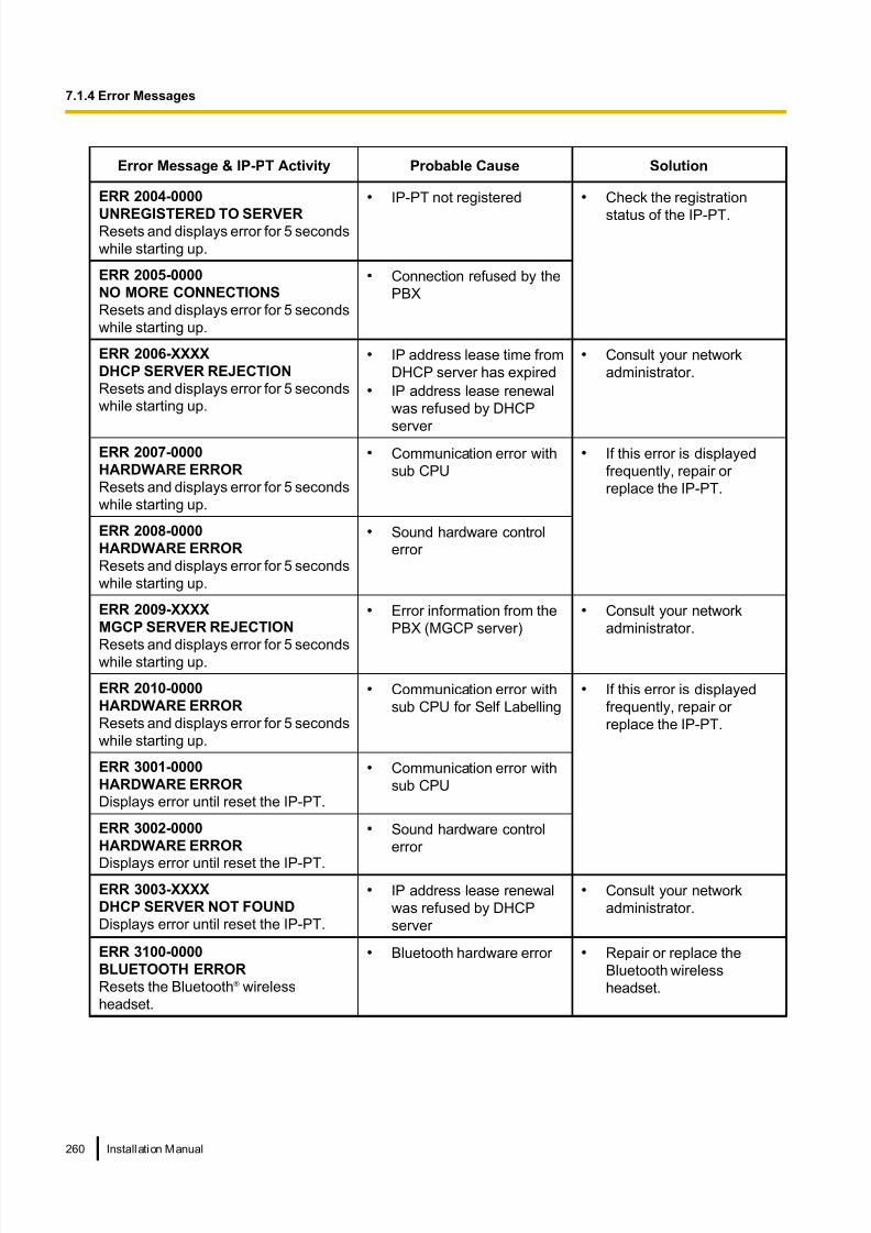
8/18/2019 NS500 Installation Manual
http://slidepdf.com/reader/full/ns500-installation-manual 260/300
Error Message & IP-PT Activity Probable Cause Solution
ERR 2004-0000
UNREGISTERED TO SERVERResets and displays error for 5 seconds
while starting up.
• IP-PT not registered • Check the registration
status of the IP-PT.
ERR 2005-0000
NO MORE CONNECTIONS
Resets and displays error for 5 seconds
while starting up.
• Connection refused by the
PBX
ERR 2006-XXXX
DHCP SERVER REJECTION
Resets and displays error for 5 seconds
while starting up.
• IP address lease time from
DHCP server has expired
• IP address lease renewal
was refused by DHCP
server
• Consult your network
administrator.
ERR 2007-0000
HARDWARE ERROR
Resets and displays error for 5 seconds
while starting up.
• Communication error with
sub CPU
• If this error is displayed
frequently, repair or
replace the IP-PT.
ERR 2008-0000
HARDWARE ERROR
Resets and displays error for 5 seconds
while starting up.
• Sound hardware control
error
ERR 2009-XXXX
MGCP SERVER REJECTION
Resets and displays error for 5 secondswhile starting up.
• Error information from the
PBX (MGCP server)
• Consult your network
administrator.
ERR 2010-0000
HARDWARE ERROR
Resets and displays error for 5 seconds
while starting up.
• Communication error with
sub CPU for Self Labelling
• If this error is displayed
frequently, repair or
replace the IP-PT.
ERR 3001-0000
HARDWARE ERROR
Displays error until reset the IP-PT.
• Communication error with
sub CPU
ERR 3002-0000
HARDWARE ERROR
Displays error until reset the IP-PT.
• Sound hardware control
error
ERR 3003-XXXX
DHCP SERVER NOT FOUND
Displays error until reset the IP-PT.
• IP address lease renewal
was refused by DHCP
server
• Consult your network
administrator.
ERR 3100-0000
BLUETOOTH ERROR
Resets the Bluetooth® wireless
headset.
• Bluetooth hardware error • Repair or replace the
Bluetooth wireless
headset.
260 Installation Manual
7.1.4 Error Messages

8/18/2019 NS500 Installation Manual
http://slidepdf.com/reader/full/ns500-installation-manual 261/300
7.1.5 Restarting the KX-NS500
If the PBX does not operate properly, restart the PBX using Web Maintenance Console. Before restarting the
PBX, try the system feature again to confirm whether there definitely is a problem or not.
Note
• When the System Mode Switch is set to "NORMAL", restarting the PBX causes the following:
– Camp-on is cleared.
– Calls on hold are terminated.
– Calls on exclusive hold are terminated.
– Calls in progress are terminated.
– Call park is cleared.
Other data stored in memory, except the above, are not cleared.
• Be aware that restarting the PBX with the System Mode Switch in the "SYSTEM INITIALIZE" position
clears all data stored in the PBX. Do not perform this operation unless you intend to delete all data
from the PBX.• When the PBX is set to obtain IP addressing information automatically, and the PBX is not able to
obtain appropriate IP addressing information from an external DHCP server, the PBX starts up with its
default IP addresses and the STATUS indicator on the front of the cabinet turns red. For the default IP
addresses, refer to "5.3 Starting Web Maintenance Console".
Operation
If the PBX does not operate properly:
1. Slide the System Mode Switch to the "NORMAL" position.
System Mode Switch
2. Start the Web Maintenance Console.
3. Log in using the Installer level account.
4. On the Home screen, click Maintenance ® System Control ® System Reset.
5. Follow the prompts.
Restarting the PBX will start.
Note
• When the power switch is turned on, or when the PBX recovers from a power failure, the PBX will
restart. The time required to restart depends on the number of connected extensions.
Installation Manual 261
7.1.5 Restarting the KX-NS500

8/18/2019 NS500 Installation Manual
http://slidepdf.com/reader/full/ns500-installation-manual 262/300
Example:
PBX Extensions Estimated Time for Starting Up
KX-NS500 128 KX-UT series SIP phones more than 5 minutes
• PBX functions cannot be used until restarting is complete. The use of a UPS is recommended; even
a momentary power failure can result in a long delay as the PBX restarts, requiring the time as shown
above.
262 Installation Manual
7.1.5 Restarting the KX-NS500
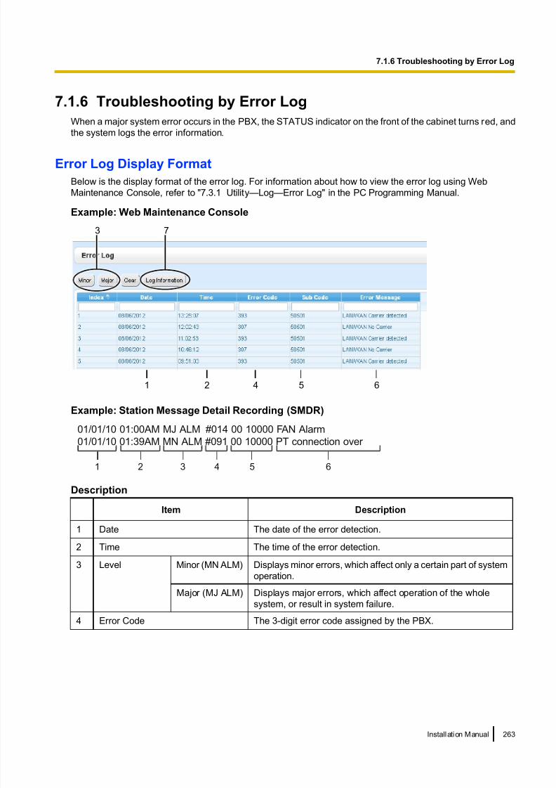
8/18/2019 NS500 Installation Manual
http://slidepdf.com/reader/full/ns500-installation-manual 263/300
7.1.6 Troubleshooting by Error Log
When a major system error occurs in the PBX, the STATUS indicator on the front of the cabinet turns red, and
the system logs the error information.
Error Log Display Format
Below is the display format of the error log. For information about how to view the error log using Web
Maintenance Console, refer to "7.3.1 Utility—Log—Error Log" in the PC Programming Manual.
Example: Web Maintenance Console
3 7
1 2 4 5 6
Example: Station Message Detail Recording (SMDR)01/01/10 01:00AM MJ ALM #014 00 10000 FAN Alarm
01/01/10 01:39AM MN ALM #091 00 10000 PT connection over
1 2 3 4 5 6
Description
Item Description
1 Date The date of the error detection.
2 Time The time of the error detection.
3 Level Minor (MN ALM) Displays minor errors, which affect only a certain part of system
operation.
Major (MJ ALM) Displays major errors, which affect operation of the whole
system, or result in system failure.
4 Error Code The 3-digit error code assigned by the PBX.
Installation Manual 263
7.1.6 Troubleshooting by Error Log

8/18/2019 NS500 Installation Manual
http://slidepdf.com/reader/full/ns500-installation-manual 264/300
Item Description
5 Sub Code SMDR:
The 8-digit sub code of the relevant hardware (BBWXYYZZ).Web Maintenance Console:
The 6-digit sub code of the relevant hardware (WXYYZZ).
For details about the contents of error sub codes, refer to
"7.3.1 Utility—Log—Error Log" in the PC Programming
Manual.
6 Error Message A description of the error.
7 Log Information Displays probable causes of the errors and their solutions.
264 Installation Manual
7.1.6 Troubleshooting by Error Log

8/18/2019 NS500 Installation Manual
http://slidepdf.com/reader/full/ns500-installation-manual 265/300
Section 8
Networking Information
This section provides information about topics such as
using the PBX in a VoIP network, and the TCP ports
used by the PBX.
Installation Manual 265

8/18/2019 NS500 Installation Manual
http://slidepdf.com/reader/full/ns500-installation-manual 266/300
8.1 Information about Using an IP NetworkThis section explains common IP network information necessary for setting up QSIG networks.
8.1.1 Using a VoIP Network with the PBX
This PBX supports Panasonic KX-NT300 series, KX-NT500 series, and KX-NT265 IP proprietary telephones
(IP-PTs), Panasonic IP softphones, and SIP (Session Initiation Protocol) phones (hardphones and softphones)
for communication on a Voice over Internet Protocol (VoIP) network. These IP telephones can be used as
extensions of the PBX when the local office LAN is connected to other LANs at different locations.
This PBX also enables VoIP communication with PBXs installed at different locations. Since the communication
does not take place over conventional telephone network, the high cost of long distance communication is
virtually eliminated.
To establish a VoIP network, the virtual cards are used according the requirement of the network. For details
about virtual cards, see "4.4 Virtual Cards".
The following diagrams illustrate VoIP network with (i) a remote office LAN and (ii) another PBX installed at
different location.
Note
Panasonic IP Cell Station (IP-CS) units are also supported by this PBX for communication on a VoIP
network. For details, refer to the Quick Installation Guide for the IP-CS.
(i) Connection Outline of VoIP Network with Remote Office LAN
SIP Phone
Extn. 102
IP-PT
Extn. 101
DHCP Server
Remote Office LAN
Local Office LAN
Router
Switching
Hub
PBX with
V-IPEXT32 card/
V-SIPEXT32 card
IP Softphone Extn. 103
Private
IP Network
IP-PT
Extn. 104Switching
Hub
IP SoftphoneExtn. 105
Router
SIP Phone
Extn. 106
266 Installation Manual
8.1.1 Using a VoIP Network with the PBX

8/18/2019 NS500 Installation Manual
http://slidepdf.com/reader/full/ns500-installation-manual 267/300
(ii) Connection Outline of VoIP Network with PBX in Other Network
Router
Switching Hub
Router
Switching Hub
PBX with
V-IPGW16 card
Branchranch
Headquarterseadquarters
PBX with
V-IPGW16 card
Private IP Network
Network Parameters
You will need to have the following IP addressing and QoS information to establish VoIP communication on
your network. This information is typically supplied by a network administrator.
Consult your network administrator for specific values.
Parameter Description
IP telephone IP AddressIdentifies the location of IP telephones on the network. Each IP
telephone must have a unique IP address.
Subnet Mask Address
Defines which digits of an IP address are used for the network
address and the host address at each network location. The IP
addresses of the IP telephones and the PBX must fall within the same
subnet as that of the default gateway (e.g., router) of the LAN.
Default Gateway Address
Identifies the IP address of the primary gateway (typically a router or
similar device) that exchanges IP packets with the other gateways on
the VoIP network.
Installation Manual 267
8.1.1 Using a VoIP Network with the PBX

8/18/2019 NS500 Installation Manual
http://slidepdf.com/reader/full/ns500-installation-manual 268/300
Parameter Description
PBX IP AddressIdentifies the location of the PBX in the network during VoIP
communications.
VLAN ID
Identifies the ID of the logical segment within the corporate LAN,
through which voice packets from IP telephones travel. For details,
refer to "8.1.3 VLAN (Virtual LAN)".
DiffServ (DS)
Identifies the value for the DS field in the header of IP packets, which
determines the priority given to packets travelling from IP telephones.
For details, refer to "5.7.4 Setting Diffserv Parameters".
Types of IP Network
The speech quality depends on the type of IP network in use. Managed IP networks provide better speech
quality compared to unmanaged networks such as satellite communications, where quality of service cannotbe guaranteed.
Examples of recommended IP networks
• Digital Leased Line
• IP-VPN (Virtual Private Network)
• Frame Relay
Not recommended
• Satellite communications (Very Small Aperture
Terminal system [VSAT], etc.)
Note
• Peer-to-peer calls between IP telephones installed at different locations may not be possible if packet
communication cannot be established between the respective networks. In this case, you need to
configure the network settings (e.g., a VPN router when using an IP-VPN) to establish packet
communication.• Unlike an IP-VPN, which is set up over a network provider’s own IP network, an Internet VPN is set up
over the Internet. Internet VPNs are not recommended for VoIP communication because transmission
delays and loss of data are likely to occur.
268 Installation Manual
8.1.1 Using a VoIP Network with the PBX

8/18/2019 NS500 Installation Manual
http://slidepdf.com/reader/full/ns500-installation-manual 269/300
8.1.2 DHCP (Dynamic Host Configuration Protocol) Server
To establish communication over a VoIP network, IP addresses must be assigned to IP telephones and the
PBX to identify their locations on the network. While these addresses can be assigned manually, it is also
possible to use a DHCP server to automatically assign IP address information. The KX-NS500 has a DHCP
Server feature. Therefore, the PBX can act as a DHCP server or DHCP client depending on its settings. When
the PBX’s DHCP Server feature is enabled, it allows you to centrally manage and automate the assignment
of IP addresses with Web Maintenance Console. For details, refer to " DHCP Server" in the PC Programming
Manual.
Assign IP addressinformation to an IP
telephone
When the mother board is
connected to the networkWhen an IP telephone is
connected to the network
Request IP address
information1
Assign IP address
information to the
DSP cards
2
Request IP address
information3
4
PBX
(DHCP Server
feature enabled)
DSP Card
IP Telephone
Note
• The DHCP Server feature is disabled by default. To enable the feature, refer to "5.4.2 Enabling the
DHCP Server Feature".
• An IP telephone and the mother board/DSP cards cannot request IP addresses from a DHCP server
on another LAN (connected through an IP network). They can only receive IP addresses from a DHCP
server on the same LAN. Therefore, when IP telephones are located on several LANs, a DHCP server
is required on each LAN. If a DHCP server is not present on the LAN, IP addresses for IP telephones
and the mother board/DSP cards on that LAN must be assigned manually.
• When the PBX has been set to act as a DHCP client, use an external DHCP server to assign IP addressinformation automatically.
• When the KX-NS500 is set as the DHCP client and cannot receive appropriate IP addressing
information from an external DHCP server, the PBX keeps using the previous effective IP addressing
information and checks whether any overlapping of IP addresses exists. If the IP address of the PBX
overlaps with another IP address, the PBX displays a warning to encourage changing the IP address
of the PBX.
Installation Manual 269
8.1.2 DHCP (Dynamic Host Configuration Protocol) Server

8/18/2019 NS500 Installation Manual
http://slidepdf.com/reader/full/ns500-installation-manual 270/300
8.1.3 VLAN (Virtual LAN)
VLANs are logical segments within a corporate LAN. By assigning VLAN settings to IP telephones, it is possible
to separate the packets transmitted by an IP telephone according to the type of data and specify which VLAN
each data type will be sent over. This allows you to avoid generating unnecessary network traffic on each
segment and to reduce the load on the network. As a consequence, speech quality can be assured. Therefore,
we recommend using the VLAN feature to perform VoIP communication effectively.
Some IP telephones (e.g., KX-NT300 series) are equipped with 2 ports, primary and secondary, for packet
communication. Allocating these ports to different VLANs enables you to split the paths for packets depending
on whether the packet contains voice signals or data.
VLAN settings (VLAN ID and VLAN priority) for the primary port affect voice data transmitted by the IP
telephone, whereas VLAN settings for the secondary port apply to data transmitted by a PC connected to the
IP telephone. When sending packets, the IP telephone can attach information on which VLAN the packets are
to be transmitted over (VLAN Tagging). The switching hub that receives these packets reads the VLAN
information and sends the packets over the appropriate VLAN. This helps to ensure bandwidth for IP telephone
voice transmissions.In this way, an IP telephone with 2 ports can transmit voice packets from the primary port with higher priority
than other packets from the secondary port.
Notice
The PBX’s LAN port does not support VLAN tagging. Therefore, connect the PBX’s LAN port to a port of
the switching hub that is set to "Untagged", and the IP telephone to a port set to "Trunk", to allow VLAN
tagging. Consult your network administrator for details.
PBX
IP Telephone with 2 ports
V L A N 1
V L A N 1
VLAN 1
V L A N 2
VLAN 2
VLAN 1
Segment for Voice Data
VLAN 2
Segment for Other Data
Voice Packet
Other Packet
PC
PC
Other Packet
V L A N 2
VLAN-capable Switching Hub
Primary Secondary
Untagged
270 Installation Manual
8.1.3 VLAN (Virtual LAN)

8/18/2019 NS500 Installation Manual
http://slidepdf.com/reader/full/ns500-installation-manual 271/300
Note
• This VLAN feature complies with IEEE (Institute of Electrical and Electronics Engineers) 802.1Q.
• The PBX receives VLAN settings only from the connected switching hub. Therefore, VLAN settings for
the PBX must be assigned at the switching hub.• When using the VLAN feature on the network, make sure that the main unit is connected to a layer 2
switch that is IEEE 802.1Q compliant, and that is configured for VLANs. In addition, the port of the
switching hub to which the card is connected must be set to "Untagged". Consult your network
administrator for details.
• When using the VLAN feature on the network, make sure that the switching hub to be connected is
IEEE 802.1Q compliant and is configured for VLANs. In addition, the port of a switching hub that the
IP telephone is connected to must be set to "Trunk" port, to allow VLAN tagging. Consult your network
administrator for details.
• Some PC LAN cards allow VLAN settings to be assigned. However, when using a PC connected to an
IP telephone with 2 ports, the VLAN settings for PC communications must be assigned only to the
secondary port of the IP telephone. Any VLAN settings assigned to the PC LAN card must be disabled.
These settings can usually be identified by "802.1Q", "802.1p", or "VLAN" in their name.• If you are using an IP telephone with a primary port only (e.g., KX-NT265), a PC cannot be connected
to the IP telephone.
8.1.4 Jitter Buffer
When voice signals are packetised and transmitted, individual packets can take different paths through the
network and arrive at the destination at varied timings. This is referred to as "jitter", and it can cause degradation
in speech quality. To compensate for jitter problems, the "jitter buffer" accumulates the packets temporarily for
processing.
To set the size of the jitter buffer, refer to "9.2.2 PBX Configuration—[1-1] Configuration—Slot—System
Property—Site—VoIP-DSP Options" in the PC Programming Manual.
8.1.5 Voice Activity Detection (VAD)
VAD conserves bandwidth by detecting silent periods during a call and suppressing the packets of silence from
being sent to the network. This feature can be enabled or disabled for codec G.711.
To configure the VAD feature, refer to the appropriate section in the PC Programming Manual.
Installation Manual 271
8.1.5 Voice Activity Detection (VAD)

8/18/2019 NS500 Installation Manual
http://slidepdf.com/reader/full/ns500-installation-manual 272/300
8.1.6 Network Configuration
You must evaluate the structure of the existing network to see if a VoIP network can be implemented. Below
are the points that should be evaluated.
Is the IP network a managed network?
A VoIP network should be implemented on a managed IP network such as Frame Relay, Leased Line, or
IP-VPN (Virtual Private Network).
An unmanaged network, such as the Internet (including an Internet VPN), cannot be used to employ a VoIP
network because delays and loss in data transmission can cause huge degradation in speech quality.
Is it possible to have static IP addressing?
IP telephones on the network always perform VoIP communications through the PBX. Therefore, the PBX
must be assigned static IP addresses, which must be programmed to each IP telephone on the network.
Note
When the DHCP Server feature is disabled and external DHCP servers are not used, static IP addressing
must also be enabled for all IP telephones.
Does only a single router provide access to the IP network?
In a dual network, 2 routers provide access to the IP network as shown in the diagram below. However, only
one router can be used as an access point to the network.
Therefore, in the diagram below, if router A, whose IP address is assigned as the default gateway IP address
of the PBX and the IP telephones, fails, VoIP communications are no longer possible; they are not able to
switch their default gateway from router A to router B to access the IP network.
IP Network
Router A Router B
Default gateway ofthe PBX: Router A
Default gateway ofthe IP Telephone:
Router A
272 Installation Manual
8.1.6 Network Configuration

8/18/2019 NS500 Installation Manual
http://slidepdf.com/reader/full/ns500-installation-manual 273/300
How is the PBX connected to remote extensions?
When the PBX is connected to a remote extensions via public IP network without using IP-VPN, address
translation techniques (e.g., NAT/NAPT) are used. These methods prevent VoIP communications from being
carried out effectively. In such cases, the use of an SBC will avoid this problem.
Note
• An SBC is not required for:
– Connections via a Wide Area Ethernet or LAN
– Connections via IP-VPN
• An SBC is required for:
– Connections via a public IP network
Router
Global IP Address
Domain
Local IP Address
Domain
Local IP Address
Domain
Connection via IP-VPN
IP-VPN
Router
Switching Hub
Switching Hub
Local IP Address
Domain
Connection via Wide Area Ethernet or LAN
Wide AreaEthernet/
LAN
Installation Manual 273
8.1.6 Network Configuration

8/18/2019 NS500 Installation Manual
http://slidepdf.com/reader/full/ns500-installation-manual 274/300
Global IP Address
Domain
Local IP Address
Domain
Local IP Address
Domain
Connection via Public IP Network
Public
IP Network
Router
SBC
Router
274 Installation Manual
8.1.6 Network Configuration

8/18/2019 NS500 Installation Manual
http://slidepdf.com/reader/full/ns500-installation-manual 275/300
Are the network devices located appropriately for effective VoIPcommunications?
Transmission delays can cause pauses and loss in VoIP communications. The more network devices (e.g.,
routers and switching hubs) there are between the PBX and IP telephones or the IP network interface, the
longer the transmission delays. This is because a certain amount of delay is inevitable when packets go through
each network device.
To prevent unnecessary delays, it is recommended to connect the PBX as close to the IP telephones and the
IP network interface as possible so that the number of the network devices is kept to a minimum.
IP Network
Router Router
Switching
Hub
Switching
Hub
Switching
Hub
Installation Manual 275
8.1.6 Network Configuration

8/18/2019 NS500 Installation Manual
http://slidepdf.com/reader/full/ns500-installation-manual 276/300
8.1.7 Network Devices
You must evaluate the network devices that are used in the existing network to see if a VoIP network can be
implemented. Below are the points that should be evaluated.
Can the firewall pass packets appropriately?
If the VoIP network contains a firewall, the firewall must be configured appropriately to allow VoIP packets to
pass through the network without being blocked by filtering. For details about the protocols and port numbers
that the PBX uses for VoIP communication, refer to "8.5 Port Security".
The ports for which you need to configure the firewall may vary depending on the network conditions.
For more information, consult your network administrator.
Are layer 2 or higher switches used?
Use of repeater hubs can increase the network load, and therefore may result in degradation in speech quality.To ensure high speech quality, use only layer 2 or higher switches. Use of layer 2 or higher switches is also
strongly recommended for connecting IP telephones.
Note
Note that the port of the switching hub that connects to the mother board should be set to operate under
"Auto Negotiation" mode.
Are Category 5 (CAT 5) or higher cables used for 10BASE-T/100BASE-TX?
When connecting network devices, make sure to use CAT 5 or higher cables for 10BASE-T/100BASE-TX
connection. If other types of cables are used, communication may not be carried out normally.
276 Installation Manual
8.1.7 Network Devices

8/18/2019 NS500 Installation Manual
http://slidepdf.com/reader/full/ns500-installation-manual 277/300
8.1.8 QoS (Quality of Service)
Some routers permit the configuration of priority control features. This allows the router to give higher priority
to voice packets and lower the rate of loss and delays during transmissions, hence improving speech quality.
It is strongly recommended that you use this feature, especially in networks where traffic is heavy.
Typically, a router identifies what packets to pass in priority by checking the value in the ToS field of the header
of IP packets. The V-IPGW16 card has the ability to set the ToS field of outgoing voice packets. When the card
is appropriately configured, the router can give voice packets from the card higher priority.
Consult your network administrator when setting the ToS field, as the setting value must conform to the
router’s specifications.
Note
• Some switches also permit the configuration of priority control features. For more information, consult
your network administrator.
• To adjust the value in the ToS field, refer to "9.11 PBX Configuration—[1-1]
Configuration—Slot—V-IPGW—Shelf Property" in the PC Programming Manual.
Installation Manual 277
8.1.8 QoS (Quality of Service)

8/18/2019 NS500 Installation Manual
http://slidepdf.com/reader/full/ns500-installation-manual 278/300
8.1.9 Network Time Protocol (NTP)
The KX-NS500 can be configured to contact an NTP server to receive and update its time setting automatically.
KX-UT series SIP phones can receive and update their time setting either through the KX-NS500 or by
contacting an NTP server directly.
For a SIP phone to receive and update its time setting via the KX-NS500, the NTP server feature must be
enabled. To enable this feature refer to "27.2.4 Network Service—[2-5] Server Feature—NTP" in the PC
Programming Manual.
If the NTP server feature is enabled:
• Case 1: An NTP server is specified in Web Maintenance Console.
– The SIP phones use the specified IP address and contact the NTP server directly.
• Case 2: An NTP server is not specified in Web Maintenance Console.
– The SIP phones use the IP address of the KX-NS500 as their NTP server.
(The KX-NS500 acts as an NTP server for the SIP phones.)
To specify the IP address of the NTP server, refer to "10.1.2 PBX Configuration—[2-1-2] System—Date &
Time—SNTP / Daylight Saving" in the PC Programming Manual.
If the NTP server feature is disabled, the SIP phones use their own time settings.
278 Installation Manual
8.1.9 Network Time Protocol (NTP)

8/18/2019 NS500 Installation Manual
http://slidepdf.com/reader/full/ns500-installation-manual 279/300
8.2 H.323 TrunksThis section explains information that is necessary for setting up a H.323 QSIG network over an IP network.
8.2.1 Avoid Multiple IP Networks
A huge degradation in speech quality will be produced when calls are made through multiple IP networks as
shown below; therefore, it is recommended that you avoid establishing a VoIP network in this fashion.
IP Network 1 IP Network 2
PSTN/
BRI QSIG, etc.
IP Network 1 IP Network 2
Installation Manual 279
8.2.1 Avoid Multiple IP Networks

8/18/2019 NS500 Installation Manual
http://slidepdf.com/reader/full/ns500-installation-manual 280/300
8.2.2 Gatekeeper
The following are the general functions of a gatekeeper:
• Dialled number-to-IP address translation• Authentication
• Bandwidth control
The gatekeeper provides these network management functions to registered clients. To register with the
gatekeeper, you need to configure the V-IPGW16 card to use the gatekeeper and programme the GK Settings
table through system programming. For details, refer to "9.11 PBX Configuration—[1-1]
Configuration—Slot—V-IPGW—Shelf Property— Gatekeeper Available" and "9.11.1 PBX
Configuration—[1-1] Configuration—Slot—V-IPGW—Shelf Property—GK Settings" in the PC Programming
Manual. After programming, the V-IPGW16 card attempts to register with the gatekeeper using registration
information such as the IP address of the mother board, and destination telephone numbers specified in the
GK Settings table.
Note
• For more information about gatekeeper functions, consult the documentation of the gatekeeper.
• When using a gatekeeper, make sure to choose a compatible model. For more information about
gatekeeper compatibility with the V-IPGW16 card, consult a certified dealer.
8.2.3 Bandwidth Assessment
When using the IP telephones and V-IPGW16 card, you must ensure that the IP network in use has enough
bandwidth to support VoIP communications. If the amount of bandwidth required for VoIP communications is
more than the network can accommodate, speech quality will be compromised. In addition, there may be an
adverse effect on the performance of other applications (e.g., e-mail or Web applications) that use the same
network. Therefore, care must be taken when assessing bandwidth requirements.
Inform your network administrator of the required bandwidth, and make sure that the network can support VoIPcommunications even under conditions of maximum network traffic.
Bandwidth Assessment for IP Extension Card
Required Bandwidth per IP Telephone for a Call
The required bandwidth depends on what combination of codecs and packet sending intervals is used. Keep
in mind the following points about the type of codecs and packet sending intervals, in terms of speech quality:
• The speech quality of the codecs varies as follows: (High) G.722, G.711, G.729A (Low)*1
• The shorter the packet sending interval, the higher the speech quality.
• The higher the speech quality the IP telephones provide, the more bandwidth the IP telephones require.*1 When the preferred codec of each party differs, the call will be established using the lower codec. For example, if the caller prefers
G.711 while the called party prefers G.729A, the call will be established using G.729A.
Codec
Packet Sending Interval
20 ms 30 ms 40 ms 60 ms
G.722*1/G.711 87.2 kbps 79.5 kbps — —
G.729A 31.2 kbps 23.5 kbps 19.6 kbps 15.7 kbps
*1 G.722 is only available for calls between KX-NT300 series IP-PTs, KX-NT500 series IP-PTs, and some SIP phones that support this
codec during peer-to-peer communication. For details, refer to "5.2.3 Peer-to-Peer (P2P) Connection" in the Feature Guide.
280 Installation Manual
8.2.3 Bandwidth Assessment

8/18/2019 NS500 Installation Manual
http://slidepdf.com/reader/full/ns500-installation-manual 281/300
Required Bandwidth for Each IP Extension Card
To allow all IP telephones to make calls simultaneously, it is necessary to keep available the bandwidth required
by an IP extension card with the maximum number of IP telephones connected.
Provided below is the formula to calculate the amount of bandwidth required for each IP extension card.When using the V-IPEXT32/V-SIPEXT32 card:
Required Bandwidth = (Required Bandwidth per IP telephone ´ 32)
Bandwidth Assessment for V-IPGW16 Card
Required Bandwidth for One VoIP Channel
The required bandwidth depends on what combination of codecs and packet sending intervals is used. Keep
in mind the following points about the type of codec and packet sending interval, in terms of the speech quality:
• The speech quality of the G.711 codec is higher than that of the G.729A codec.
• The shorter the packet sending interval, the higher the speech quality.
• The higher the speech quality the V-IPGW16 card provides, the more bandwidth the card requires.
Via LAN
Codec
Packet Sending Interval
20 ms 30 ms 40 ms 60 ms 90 ms
G.711 87.2 kbps 79.5 kbps 75.6 kbps 71.7 kbps —
G.729A 31.2 kbps 23.5 kbps 19.6 kbps 15.7 kbps —
Via WAN (PPP: Point-to-Point Protocol)
Codec
Packet Sending Interval
20 ms 30 ms 40 ms 60 ms 90 ms
G.711 84 kbps 77.3 kbps 74 kbps 70.7 kbps —
G.729A 28 kbps 21 kbps 18 kbps 14.7 kbps —
Bandwidth Calculation
Provided below is the formula to find out the amount of bandwidth required for VoIP communications:
Required Bandwidth
= (No. of Fax Machines ´ Required Bandwidth for the G.711 codec) +
[(16 - No. of Fax Machines) ´ Required Bandwidth for Voice Communication]
Example
Consider the following case as an example:
• Communication: via LAN
• No. of Fax Machines: 2
• G.711 Packet Sending Interval: 20 ms (requiring 87.2 kbps per channel)
• G.729A Packet Sending Interval for Voice Communication: 20 ms (requiring 31.2 kbps per channel)
In this case, the required bandwidth will be as follows:
Required Bandwidth
= (2 ´ 87.2) + [(16 - 2) ´ 31.2]
= 611.2 (kbps)
Installation Manual 281
8.2.3 Bandwidth Assessment

8/18/2019 NS500 Installation Manual
http://slidepdf.com/reader/full/ns500-installation-manual 282/300
Therefore, inform your network administrator and make sure that the network can support a bandwidth of
611.2 kbps even when the network is under conditions of maximum traffic.
Note
It is recommended that all cards on a VoIP network have the same packet sending interval.
Additional Information
As described above, it is possible to control the required bandwidth by selecting a certain combination of codec
and packet sending interval. However, it is also possible to control required bandwidth by limiting the number
of available virtual VoIP channels.
The V-IPGW16 card supports a total of 8 ports, each having 2 separate channels. By disabling some of the
ports, you can reduce the bandwidth required for VoIP communications.
To limit the number of VoIP channels:
Set the status of the ports you wish to disable (starting from the highest-numbered port) to OUS.
For example, if you wish to use only 10 of the available 16 virtual VoIP channels (i.e., disable 6 channels), set
ports 8, 7, and 6 to OUS as shown below:
In this case, the equation for bandwidth calculation, based on the previous example, will change as follows:
Required Bandwidth
= (No. of Fax Machines ´ Required Bandwidth for the G.711 codec) +
[(10 - No. of Fax Machines) ´ Required Bandwidth for Voice Communication]
= (2 ´ 87.2) + [(10 - 2) ´ 31.2]
= 424 (kbps)
282 Installation Manual
8.2.3 Bandwidth Assessment
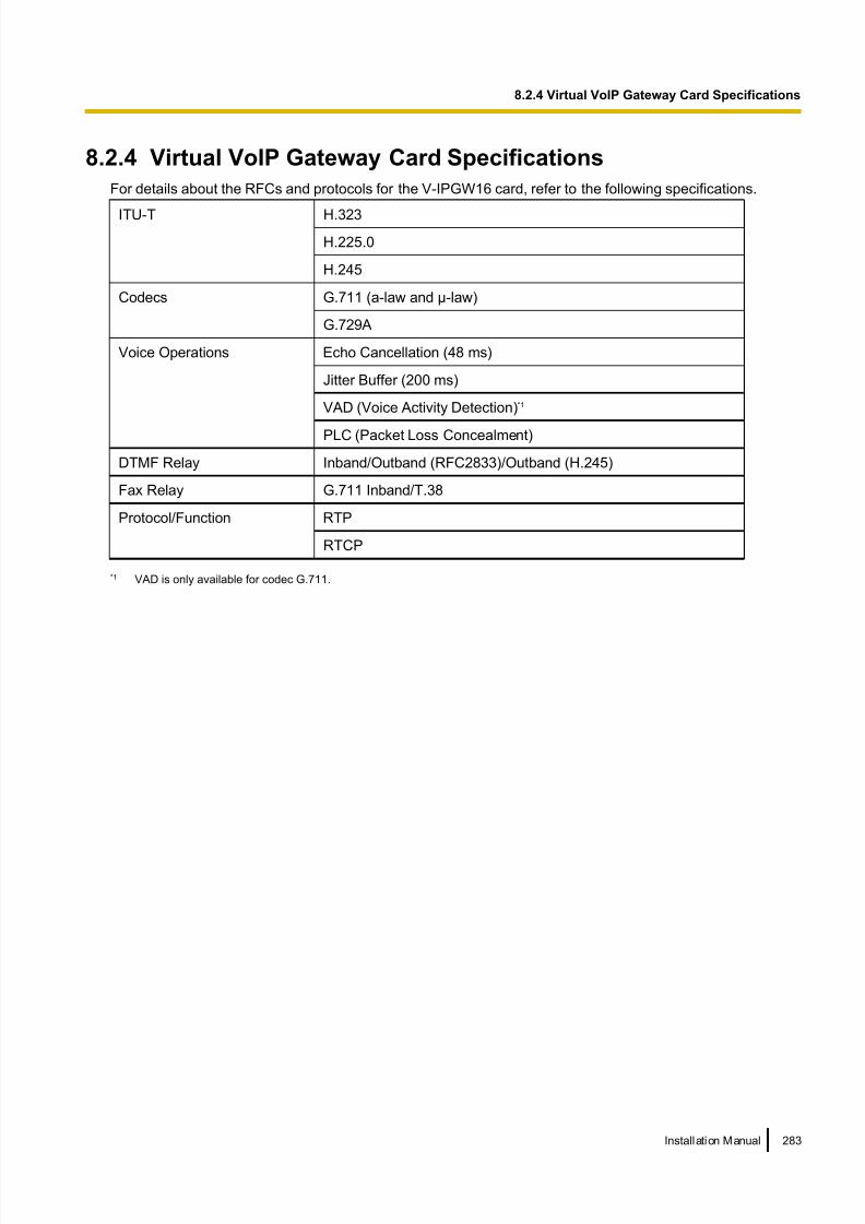
8/18/2019 NS500 Installation Manual
http://slidepdf.com/reader/full/ns500-installation-manual 283/300
8.2.4 Virtual VoIP Gateway Card Specifications
For details about the RFCs and protocols for the V-IPGW16 card, refer to the following specifications.
ITU-T H.323
H.225.0
H.245
Codecs G.711 (a-law and µ-law)
G.729A
Voice Operations Echo Cancellation (48 ms)
Jitter Buffer (200 ms)
VAD (Voice Activity Detection)*1
PLC (Packet Loss Concealment)
DTMF Relay Inband/Outband (RFC2833)/Outband (H.245)
Fax Relay G.711 Inband/T.38
Protocol/Function RTP
RTCP
*1 VAD is only available for codec G.711.
Installation Manual 283
8.2.4 Virtual VoIP Gateway Card Specifications

8/18/2019 NS500 Installation Manual
http://slidepdf.com/reader/full/ns500-installation-manual 284/300
8.3 SIP TrunksThis section provides information on using SIP trunks with the PBX.
8.3.1 IP Telephony Service
The Virtual 16-Channel SIP Trunk Card (V-SIPGW16) is a virtual trunk card which is designed to be easily
integrated into an Internet Telephony Service provided by an ITSP (Internet Telephony Service Provider).
As a major SIP Provider, an ITSP provides its telephony service partly through the conventional telephone
network (e.g., ISDN and Mobile), which is fee-based. An ISP (Internet Service Provider), another major SIP
Provider, does not provide telephone connection itself. However, providing its users with Internet access, an
ISP provides voice communication on the Internet for free. In this way, with VoIP technology based on the SIP
protocol, the cost of voice communication can be much cheaper than conventional telephone networks. A
maximum of 16 V-SIPGW16 cards can be installed to the virtual slots of the PBX. The channel capacity of the
card allows users to connect to up to 32 different ISP/ITSPs.
V-SIPGW16 Connection Outline
The following diagram illustrates a simple VoIP network connecting the V-SIPGW16 card to the Internet.
PBX withV-SIPGW16 Card
PC
LAN (Local Area Network)
WAN (Wide Area Network)
Internet
LocalTelephone
IP-PT
ISP
ITSP
Router
SwitchingHub
Requirements for Internet Telephony Service
• You need to subscribe with an ISP for Internet connection.
284 Installation Manual
8.3.1 IP Telephony Service

8/18/2019 NS500 Installation Manual
http://slidepdf.com/reader/full/ns500-installation-manual 285/300
• You need to subscribe with an ITSP for telephone connection. The ISP and ITSP may be part of the same
company.
Note
• VoIP communication using the V-SIPGW16 card may deteriorate depending on the ITSP being used.
• VoIP communication using the V-SIPGW16 card may deteriorate depending on the network conditions.
DNS (Domain Name System)
A DNS server normally provides the name resolution service for your PC. As domain names are alphabetic,
they are easier to remember. The Internet, however, is based on IP addresses. Therefore, every time a domain
name is used, a DNS server must translate the name into the corresponding IP address, and vice versa. For
example, the domain name www.example.com may be translated to 192.0.34.166 . If one DNS server does
not know how to translate a particular domain name, it asks another one, and so on, until the correct IP address
is returned.
NAT Traversal
When NAT/NAPT (Network Address Port Translation) is enabled, the router translates a local IP address from
the PBX into a global IP address. However, the router with NAT enabled does not translate local IP addresses
stored in SIP messages into global IP addresses.
Therefore, the address which the SIP Server recognises as the destination IP address to reply to is actually
the local IP address of the PBX, not the global IP address of the router. Therefore, if the SIP Server receives
a SIP message from the PBX and sends a message back to the PBX using the address stored in the SIP
message, the packet information will not reach the PBX.
STUN Servers function to solve the global IP address problem under certain NAT conditions, for example, incase of full duplex communication. A STUN Server, used alongside the SIP Server, finds out the global IP
address of the router with NAT enabled. With the STUN feature enabled, the packet information sent by the
SIP Server is able to "traverse" NAT and reach the PBX.
The settings can be configured to specify whether to enable the NAT Traversal feature for each ISP/ITSP. In
addition, the NAT Traversal method can be selected from "STUN" and "Fixed IP Address". For details, refer
to "9.8 PBX Configuration—[1-1] Configuration—Slot—V-SIPGW—Shelf Property" in the PC Programming
Manual.
The V-SIPGW16 card may require the NAT Traversal feature to be enabled to connect to the WAN via a router.
The following diagram illustrates how VoIP communication is enabled between the V-SIPGW16 card and the
SIP Server (SIP Receiver) via a router with NAT enabled.
Installation Manual 285
8.3.1 IP Telephony Service

8/18/2019 NS500 Installation Manual
http://slidepdf.com/reader/full/ns500-installation-manual 286/300
LAN
WAN
Internet
STUNTUN
STUNTUN
Server erver
SIIPServer erver
Fixed Iixed IP Addressddress
SIIPServer erver
STUN
STUNServer
SIPServer
Fixed IP Address
SIPServer
PBX withV-SIPGW16 Card
ISP/ITSSP ITSP
ISP/ITSSP ITSP
ISP/ITSP
ISP/ITSP
Router (NAT enabled)
PCIP-PT
SwitchingHub
Note
• If an ISP/ITSP uses a device such as SBC (Session Border Controller), you may not have to enable
the NAT Traversal feature.
• A STUN Server is supplied by an ISP/ITSP, and not included with the PBX.
286 Installation Manual
8.3.1 IP Telephony Service

8/18/2019 NS500 Installation Manual
http://slidepdf.com/reader/full/ns500-installation-manual 287/300
8.3.2 SIP Requirements
Port Requirements
Required Ports for Each Channel
When configuring a router with NAT enabled, you need to secure a certain number of ports for each SIP and
RTP/RTCP channel. For RTP/RTCP, the number of required ports is double the number of activated SIP trunks
(Ch). For SIP signalling, the number of required ports is always one regardless of the number of activated SIP
trunks (Ch).
<Example>
If 4 SIP trunk channels are activated, you need the following number of ports:
Protocol Type Required Port
RTP 4
RTCP 4
SIP 1
Total 9
Firewall Requirements
If the VoIP network contains a firewall, the firewall must be configured appropriately to allow VoIP packets to
pass through the network without being blocked by filtering. For the protocols and port numbers that the PBX
uses for VoIP communication, refer to "8.5 Port Security".
The ports for which you need to configure the firewall may vary depending on the network conditions.
For more information, consult your network administrator.
8.3.3 Router Requirements
• Port Forwarding:
It may be necessary to set the NAT router so that it forwards the incoming packets to the IP address of the
V-SIPGW16 card if all of the following conditions are met:
– the PBX uses a STUN server;
– a V-SIPGW16 card is located under a NAT router;
– incoming packets are routed to a SIP Client port or NAT Voice (RTP) UDP port indicated in "8.5 Port
Security".
• SIP-NAT Feature:When a V-SIPGW16 card is located under a NAT router that supports the SIP-NAT feature*1, it is
recommended to disable this feature.*1 When NAT is enabled, the router translates the IP address stored in the IP header and the port number stored in the UDP header.
When SIP-NAT is enabled, the router also translates the IP address and port number stored in SIP messages.
8.3.4 Bandwidth Requirements
When using the V-SIPGW16 card, you must ensure that the WAN has enough bandwidth to support VoIP
communications. Refer to the table below and ensure that the sum of the required bandwidth for each channel
is smaller than the amount the WAN (e.g., ADSL network) can provide.
Installation Manual 287
8.3.4 Bandwidth Requirements

8/18/2019 NS500 Installation Manual
http://slidepdf.com/reader/full/ns500-installation-manual 288/300
Note that the amount in the table is only a guide. Subscribe to a network that has enough bandwidth. If the
amount of bandwidth required for VoIP communications is larger than what the network can accommodate,
speech quality will be compromised.
Required Bandwidth for Each ChannelThe required bandwidth depends on what combination of codecs and packet sending interval is used. Keep
in mind the following points about the type of codec and packet sending interval, in terms of the speech quality:
• The speech quality of the codecs varies as follows: G.711 (High), G.729A (Low)
• The shorter the packet sending interval, the higher the speech quality.
• The higher the speech quality the V-SIPGW16 card provides, the more bandwidth the WAN requires.
Codec
Packet Sending Interval
10 ms 20 ms 30 ms 40 ms 50 ms 60 ms
G.711 110.4 kbps 87.2 kbps 79.5 kbps 75.6 kbps 73.3 kbps 71.7 kbps
G.729A 54.4 kbps 31.2 kbps 23.5 kbps 19.6 kbps 17.3 kbps 15.7 kbps
288 Installation Manual
8.3.4 Bandwidth Requirements

8/18/2019 NS500 Installation Manual
http://slidepdf.com/reader/full/ns500-installation-manual 289/300
8.3.5 Virtual SIP Trunk Card Specifications
For details about the RFCs and protocols for the V-SIPGW16 card, refer to the following specifications.
Items Specification
SIP RFCs RFC3261 (UDP only)
RFC3262 (PRACK)
RFC3264 (Offer/Answer)
RFC3311 (UPDATE)
RFC3581 (Symmetric Response Routing/rport)
RFC4028 (Session Timer)
Codecs G.711 (a-law and µ-law)
G.729A
Voice Options Echo Cancellation (48 ms)
Jitter Buffer (200 ms)
VAD (Voice Activity Detection)*1
PLC (Packet Loss Concealment)
DTMF Relay Inband/Outband (RFC2833)/Outband (SIP INFO)
Fax Relay G.711 Inband/T.38
Protocol/Function RTP
RTCP
DNS (A/SRV)
NAT Traversal (STUN)
QoS (ToS field setting in IP header of RTP/RTCP)
*1 VAD is only available for codec G.711.
Installation Manual 289
8.3.5 Virtual SIP Trunk Card Specifications

8/18/2019 NS500 Installation Manual
http://slidepdf.com/reader/full/ns500-installation-manual 290/300
8.4 Types of PBX NetworksThis section gives an overview of the types of networks the PBX can participate in.
8.4.1 H.323 QSIG Network
This section gives an overview of H.323 QSIG networks.
Image of a H.323 QSIG network:
Resources for Node 1
Node 1:
Main Unit*1
Resources for Node 2
Node 2:
KX-NCP500
H.323 QSIG
Network
*1 KX-NS500
Features• H.323 QSIG networks can include non-KX-NS500 PBXs (e.g., KX-TDE200, KX-NCP500).
• Resources are not available to extension users of other PBX without explicit configuration.
Conditions
• PBXs in an H.323 QSIG network must be connected over a private IP network.
Bandwidth Requirements
Refer to "8.2.3 Bandwidth Assessment".
Required Items
• V-IPGW16: Virtual 16-Channel VoIP Gateway Card
Note
• The following activation key is required for enhanced QSIG network features (NDSS, Centralised Voice
Mail, etc.).
– KX-NSN002: Activation Key for QSIG Network (QSIG Network)
• For more details about H.323 QSIG networks, refer to "4.2.1 TIE Line Service" in the Feature Guide.
• For details about configuring and programming a H.323 QSIG network, refer to " TIE Line Access"
in the PC Programming Manual.
290 Installation Manual
8.4.1 H.323 QSIG Network

8/18/2019 NS500 Installation Manual
http://slidepdf.com/reader/full/ns500-installation-manual 291/300
8.5 Port SecurityIf the VoIP network contains a firewall, the firewall must be configured appropriately to allow VoIP packets to
pass through certain ports of the ports listed below without being blocked by filtering. The ports for which youneed to configure the firewall may vary depending on the network conditions.
For more information, consult your network administrator.
The following table shows the PBX’s ports used for IP communications. Any access to the ports not in this list
is ignored.
Port Numbers for LAN Port
Port Number Protocol Application Client/Server Changeable/
Fixed
25 TCP/UDP SMTP Server Changeable
53 UDP DNS Server Fixed
67 UDP DHCP Server Changeable
68 UDP DHCP Client Changeable
80 TCP HTTP Server Changeable
123 UDP NTP Server Fixed
143 TCP IMAP Server Changeable
161 UDP SNMP Server Changeable
443 TCP HTTPS Server Changeable
465 TCP/UDP SMTP over SSL Server Changeable
993 TCP IMAP over SSL Server Changeable
1717 UDP Connectionless UDP - Changeable
1718 TCP Connectionless TCP - Changeable
1719 UDP H.225 RAS - Changeable
1720 TCP H.225 Call Signal - Changeable
2103 TCP CMM Server Fixed
2300 TCP Telnet-SMDR - Changeable
2727 UDP MGCP*1 - Changeable
3493 TCP UPS*2 - Fixed
3702 UDP WSD Server Changeable
4560–4561 UDP PSAP - Changeable
4562 UDP SSAP - Changeable
5060 UDP SIP UA (EXT) - Changeable
7547 TCP CWMP Server Changeable
7580 TCP HTTP Server Changeable
Installation Manual 291
8.5 Port Security

8/18/2019 NS500 Installation Manual
http://slidepdf.com/reader/full/ns500-installation-manual 292/300
Port Number Protocol Application Client/Server Changeable/
Fixed
8080 TCP Web Maintenance Console - Changeable
9300 UDP PTAP - Changeable
10000–
10895
TCP H.323 Dynamic Port
(H.225 Send, H.245 Send/
Receive, Connection-less
[TCP] Send Port)
- Changeable
20000 TCP UM-VMA*3 Server Fixed
30021 TCP/UDP FTP/FTPS Server Changeable
32727 UDP MGCP*1 for IP-CS - Changeable
33090 UDP ACS-MDW Server Fixed
33091
33092 TCP
33131
33321 TCP Access Point Login (Telnet) Server Changeable
33333 TCP CTI 3rd Party Connection - Changeable
33334 TCP CTI 1st Party Connection - Changeable
33478 UDP STUN Client Changeable
33702 UDP ACS-MDW (WSD) Server Fixed
35060 UDP SIP UA (CO) - Changeable
37547 TCP CWMP Server Changeable
37580 TCP HTTPS Server Changeable
39300 UDP PTAP for IP-CS - Changeable
40000–
40095
TCP/UDP FTP/FTPS-Data Server Changeable
50000–
65535
(Ephemeral)
UDP SNMP TRAP Client Fixed
TCP/UDP FTP Client
TCP/UDP FTP/FTPS-Data Client
UDP NTP Client
UDP DNS Client
UDP SYSLOG Client
TCP/UDP SMTP Client
TCP/UDP SMTP over SSL Client
TCP/UDP POP3 Client
292 Installation Manual
8.5 Port Security

8/18/2019 NS500 Installation Manual
http://slidepdf.com/reader/full/ns500-installation-manual 293/300
Port Number Protocol Application Client/Server Changeable/
Fixed
TCP/UDP ACS-MDW Server
*1 Media Gateway Control Protocol. Used for call control command data and LCD/LED data transmission.*2 Used by UPS daemon.*3 Used by Unified Messaging.
Port Numbers for Optional DSP Card
Port Number Protocol Application Client/Server Changeable/
Fixed
12000–
12767
UDP RTP/RTCP - Changeable
16000–
17023
UDP RTP/RTCP for NAT traversal - Changeable
Installation Manual 293
8.5 Port Security

8/18/2019 NS500 Installation Manual
http://slidepdf.com/reader/full/ns500-installation-manual 294/300
294 Installation Manual
8.5 Port Security

8/18/2019 NS500 Installation Manual
http://slidepdf.com/reader/full/ns500-installation-manual 295/300
Section 9
Appendix
This section provides information about PBX Region
Suffix Codes and Areas, System Prompt Languages.
Installation Manual 295

8/18/2019 NS500 Installation Manual
http://slidepdf.com/reader/full/ns500-installation-manual 296/300
9.1 PBX Region Suffix Codes and Areas According to the following table, select the appropriate Suffix Code and Area for your PBX to localise PBX
settings to your location.
For KX-NS500
Model Name Area Code
KX-NS500NE Albania
Algeria
Bosnia
Bulgaria
Croatia
Cyprus
Czech
Egypt
Estonia
Hungary
Italy
Latvia
Lithuania
Poland
Portugal
Romania
Slovakia
Slovenia
Spain
Yugoslavia (former)
Other
KX-NS500BX/KX-NS500LA/
KX-NS500SU/KX-NS500UE
BX
ZA
KX-NS500AG –
KX-NS500RU –
KX-NS500UC –
KX-NS500BR –
296 Installation Manual
9.1 PBX Region Suffix Codes and Areas

8/18/2019 NS500 Installation Manual
http://slidepdf.com/reader/full/ns500-installation-manual 297/300
9.2 System Prompt LanguagesNote
• The following abbreviations are used in the language file names: – UK: United Kingdom
– US: United States
– LA: Latin America
– CA: Canada
– BR: Brazil
• No. 1 is set by default. For details, see "24.4 UM Configuration—[5-4] System
Parameters—Parameters—Prompt Setting—Prompt Setting" in the PC Programming Manual.
System prompt languages stored in the System Memory
KX-NS500
Suffix
AG BR BX LA NE
No. 1
(Primary)
LA-Spanish BR-Portuguese US-English US-English UK-English
No. 2 US-English US-English LA-Spanish LA-Spanish Spanish
No. 3 - - French French French
No. 4 - - - - German
No. 5 - - - - Dutch
No. 6 - - - - Italian
No. 7 - - - - Swedish
No. 8 - - - - -
KX-NS500
SuffixRU SU UC UE
No. 1
(Primary)
Russian US-English Ukrainian US-English
No. 2 Ukrainian LA-Spanish Russian LA-Spanish
No. 3 US-English French US-English French
No. 4 - - - -
No. 5 - - - -
No. 6 - - - -
No. 7 - - - -
No. 8 - - - -
Installation Manual 297
9.2 System Prompt Languages

8/18/2019 NS500 Installation Manual
http://slidepdf.com/reader/full/ns500-installation-manual 298/300
System prompt languages stored in optional SD Memory Cards
KX-NS5134/
KX-NS5135/
KX-NS5136Suffix
X
No. 1
(Primary)
UK-English
No. 2 German
No. 3 Spanish
No. 4 Italian
No. 5 Swedish
No. 6 Dutch
No. 7 CA-English
No. 8 CA-French
298 Installation Manual
9.2 System Prompt Languages

8/18/2019 NS500 Installation Manual
http://slidepdf.com/reader/full/ns500-installation-manual 299/300
The KX-NS500NE is designed to interwork with the:
Analogue Public Switched Telephone Network (PSTN) of European countries
• Pan-European Integrated Services Digital Network (ISDN) using ISDN basic rate access
• Pan-European Integrated Services Digital Network (ISDN) using ISDN primary rate
access
Panasonic System Networks Co., Ltd./Panasonic System Networks Company U.K. Ltd. declares that the KX-NS500NE is
in compliance with the essential requirements and other relevant provisions of Radio & Telecommunications Terminal
Equipment (R&TTE) Directive 1999/5/EC.
Declarations of Conformity for the relevant Panasonic products described in this manual are available for download by
visiting:
http://www.doc.panasonic.de
Contact to Authorised Representative:
Panasonic Testing Centre
Panasonic Marketing Europe GmbH
Winsbergring 15, 22525 Hamburg, Germany

8/18/2019 NS500 Installation Manual
http://slidepdf.com/reader/full/ns500-installation-manual 300/300
For Future Reference
Please print, record, and retain the following information for future reference.
![dl.orino.irdl.orino.ir/central/NS500/ns500_sales_guide-02[1].pdf · PBX Line-up and Positioning of the KX-NS500 Product Concept Product Overview System 14Connection Diagram Cost Saving](https://img.pdfslide.net/doc/110x75/5e69866d67b0835d25653cc9/dlorinoirdlorinoircentralns500ns500salesguide-021pdf-pbx-line-up-and.jpg)