Embed Size (px)
Citation preview

1
NS‐HP‐GL User’s Guide
Rev. 0.3
September 30, 2017

2
Table of Contents
1. INTRODUCTION ..................................................................................................... 3
2. FEATURES OF NS‐HP‐GL ......................................................................................... 5
3. APPLICATIONS ........................................................................................................ 5
4. PIN OUT DESCRIPTION .......................................................................................... 6
5. CHECK OUT BASIC GPS FUNCTIONALITY ............................................................... 8
6. SET UP NS‐HP‐GL AS RTK BASE ........................................................................... 12
Known Base Antenna Position ............................................................................. 13
Unknown Base Antenna Position ......................................................................... 14
Base Stream Format ............................................................................................. 16
7. USE NS‐HP‐GL AS RTK ROVER ............................................................................. 18
RTK reference static started position ................................................................... 23
8. FLOAT RTK MODE ................................................................................................ 24
9. MOVING BASE MODE .......................................................................................... 26
10. ADVANCED MOVING BASE MODE .................................................................. 28
11. RTK POST PROCESSING .................................................................................... 29
12. ACTIVE ANTENNA CONSIDERATION ................................................................ 30
13. FIRMWARE UPDATE ......................................................................................... 31
14. POSSIBLE CONNECTION FOR QUADCOPTER APPLICATION ............................ 35
15. FAQ ................................................................................................................... 37

3
1. INTRODUCTION
NS‐HP‐GL is a high performance RTK capable GNSS receiver. At 1Hz update rate, NS‐HP‐GL can accept
RTCM 3.x message or SkyTraq carrier phase raw measurement data from a base station to perform
carrier phase RTK processing, achieving centimeter‐level accuracy relative positioning. At higher 2 / 4 /
5 / 8 / 10 / 20 Hz update rate, NS‐HP‐GL functions as a high‐performance GNSS receiver with
conventional meter‐level accuracy.
NS‐HP‐GL‐5 and NS‐HP‐GL‐10 models support RTK update rate up to 5Hz and 10Hz.
For UAV aerial survey applications that require camera shutter trigger signal synchronized precision
time & position stamp, NS‐HP‐GL‐5S and NS‐HP‐GL‐10S provide precise time having better than
100nsec accuracy, and precise position having maximum error less than 1 millisecond traveled
distance on top of RTK 1cm + 1ppm positioning error; i.e. if 50km/h speed then maximum 1.4cm error
on top of RTK 1cm + 1ppm positioning error.
NS‐HP‐GL Models:
Models RTK Maximum Update Rate
Precision Time/Position Stamp 1Hz 5Hz 10Hz
NS‐HP‐GL X
NS‐HP‐GL‐5 X
NS‐HP‐GL‐5S X X
NS‐HP‐GL‐10 X
NS‐HP‐GL‐10S X X
Model Suffix ‐5 ‐10
Supported Update Rate (Hz)
RTK cm‐level accuracy 1 1 / 2 / 4 / 5 1 / 2 / 4 / 5 / 8 /10
normal meter‐level accuracy2 / 4 / 5 / 8 / 10 /
20 8 / 10 / 20 20
Moving base precision heading
1 1 / 2 / 4 / 5 1 / 2 / 4 / 5
When used with RTCM base station, the supported RTCM message types are:
Type 1002 – Extended L1‐Only GPS RTK Observables
Type 1004 – Extended L1&L2 GPS RTK Observables
Type 1005 – Stationary RTK Reference Station ARP
Type 1006 – Stationary RTK Reference Station ARP with Antenna Height
Type 1074 – GPS MSM4
Type 1075 – GPS MSM5

4
Type 1076 – GPS MSM6
Type 1077 – GPS MSM7
Type 1084 – GLONASS MSM4 (only compatible with NS‐HP‐GL’s output)
Type 1085 –GLONASS MSM5 (only compatible with NS‐HP‐GL’s output)
Type 1086 –GLONASS MSM6 (only compatible with NS‐HP‐GL’s output)
Type 1087 –GLONASS MSM7 (only compatible with NS‐HP‐GL’s output)
Type 1104 – SBAS MSM4
Type 1105 – SBAS MSM5
Type 1106 – SBAS MSM6
Type 1107 – SBAS MSM7
Type 1114 – QZSS MSM4
Type 1115 – QZSS MSM5
Type 1116 – QZSS MSM6
Type 1117 – QZSS MSM7
For centimeter‐level RTK accuracy, NS‐HP‐GL requires much better operating condition than
conventional meter‐level accuracy GPS receiver:
* Baseline distance between base and rover should be under 10Km
* Under open sky without interference
* Signal level over 37dB/Hz
* 7 or more satellites above 15 degree elevation angle with good satellite geometry
If above condition is not met, NS‐HP‐GL will not get centimeter‐level accuracy RTK solution. Without
base station data input, NS‐HP‐GL works like a normal GPS receiver.
When used with a RTCM 3.x RTK base station within 10Km operating range, one rover NS‐HP‐GL is
needed. If one wishes to setup a local base station to work with rover, then two NS‐HP‐GL will be
needed, one for base and another for rover.
Default NMEA output baud rate is 115200.
RTCM 3.x or SkyTraq raw measurement data input baud rate is 57600
When NS‐HP‐GL is configured as base, it can serve as base for NS‐HP‐GL, NS‐HP‐GL‐5, NS‐HP‐GL‐10
rovers. When changing NS‐HP‐GL to base mode, baud rate need to change to 57600 to work with
other NS‐HP‐GL rovers.

5
2. FEATURES OF NS‐HP‐GL
RTK Receiver Features
* Support RTK base and rover modes
* L1 C/A Code
* 16 channel GPS/SBAS/QZSS + 12 channel GLONASS
* RTK position accuracy: centimeter‐level
* 70mA @ 3.3V
GNSS Receiver Features
* L1 C/A Code
* 16 channel GPS/SBAS/QZSS + 12 channel GLONASS
* Sensitivity: ‐148dBm cold starting, ‐160dBm tracking
* Cold start time to first fix: 29 second
* Hot start time to first fix: 1 second
* Position accuracy: 2.5m CEP
* Velocity accuracy: 0.1m/sec
* Timing accuracy: 10nsec
* Maximum 20Hz update rate
* 50mA @ 3.3V
* 1Hz carrier phase raw measurement output on TX3 pin
* 40mm x 38mm compact size
3. APPLICATIONS
Having superior precision positioning RTK capability, besides conventional GPS applications, NS‐HP‐GL
may also be used for:
1. Centimeter‐level accuracy Bluetooth RTK receiver for smartphones and tablets
2. Precise position tracking of race cars and athletes for performance measurement
3. Precision farming machine guidance
4. Precision grass cutting machine guidance
5. Precision guidance of unmanned aerial vehicles
6. Aerial survey precision position stamping without needing ground control points

6
4. PIN OUT DESCRIPTION
Pin Name Description
VCC33 Digital section power supply input, 3.3V DC
GND Digital ground
BOOT_SEL1 Input pin, 3.3V LVTTL.No connection for normal use. Pull‐low for loading firmware into empty orcorrupted Flash memory from ROM mode for the master microcontroller.
RX1 UART serial data input, 3.3V LVTTL. Used for sending commands or information to the receiver in SkyTraq binary protocol.
TX1 UART serial data output, 3.3V LVTTL. Used for sending position, time and velocity information from the receiver in NMEA‐0183 format.
TX2 UART serial data output, 3.3V LVTTL. Currently no used.
RX2 UART serial data input, 3.3V LVTTL. Used for sending RTCM 3.x data or SkyTraq raw measurement data to the receiver.
NC No connection, empty pin
TRIG* Input pin, 3.3V LVTTL.External trigger input for camera shutter synchronized precision time andposition stamping.

7
STS Position fix status indicator output, active low, 3.3V LVTTL. No position solution: output HIGH DGPS or 3D solution: output LOW 2sec, HIGH 2sec RTK float solution: output INTEGER(ratio / 0.5) + 1 pulses, each pulse LOW for0.25sec, HIGH for 0.25sec, ending with HIGH for 1sec. When connected to LED +370‐ohm resistor to 3.3V, the pulse count gives an idea of the RTK ratio valuewithout needing GNSS Viewer running on a notebook. RTK fix solution: output LOW
RFGND RF ground
RFIN RF signal input connects to antenna. 3.2V active antenna bias on RFIN.
RFVCC33 RF section power supply, 3.3V DC
VBAT Backup supply voltage for internal RTC and backup SRAM, 2.5V ~ 3.6V. VBAT must be applied whenever VCC33 is applied. This pin can be powered continuously to minimize the startup time. If VCC33 and VBAT are both removed, the receiver will be in factory default mode upon power up, all user configuration set to SRAM is lost; settings set to SRAM+Flash will remain effective. For applications the does not care cold starting every time, this pin can be connect to VCC33.
RSTN1 External active‐low reset input to the master microcontroller, 3.3V LVTTL.Only needed when power supply rise time is very slow or software controlled reset is desired.
TX3 UART serial data output, 3.3V LVTTL.Output 1Hz carrier phase raw measurement data at 115200
RSTN2 External active‐low reset input to the slave microcontroller, 3.3V LVTTL Only needed when power supply rise time is very slow or software controlled reset is desired.
BOOT_SEL2 Input pin, 3.3V LVTTL.No connection for normal use. Pull‐low for loading firmware into empty orcorrupted Flash memory from ROM mode for the slave microcontroller.
1PPS One‐pulse‐per‐second (1PPS) time mark output, 3.3V LVTTL. The rising edge synchronized to UTC second when getting 3D position fix. The pulse duration is about 800usec at rate of 1 Hz.
GND Digital ground
* Available only for NS‐HP‐GL‐5S and NS‐HP‐GL ‐10S, 5Hz and 10Hz version with precision
time/position stamping feature.

8
5. CHECK OUT BASIC GPS FUNCTIONALITY
Hook up as below, connect to an UART‐to‐USB bridge breakout board, connect antenna to RFIN, and
place antenna at a location having clear sky view. After driver for the UART‐to‐USB bridge chip has
been installed, select proper COM port and 115200 baud rate on GNSS Viewer, click CLOSE, GNSS
Viewer will show signal being acquired and tracked.

9
GNSS Viewer for Windows PC can be downloaded from:
http://navspark.mybigcommerce.com/content/GNSS_Viewer.zip
http://navspark.mybigcommerce.com/content/GNSS‐Viewer‐User‐Guide.rev0.2.pdf
If uncertain of the COM port, it can be found from the Windows Device Manager.

10
If wishing to change NMEA output baud rate, from Binary pull‐down menu select Configure Serial Port,
select desired baud rate and Update to SRAM+Flash.

11
If wishing to change NMEA solution output updated rate, from Binary pull‐down menu select
Configure Position Update Rate, select desired update rate and Update to SRAM+Flash.
When changing to higher update rate, make sure baud rate in use can accommodate it. If baud rate is
not fast enough, NMEA message output will be truncated.

12
6. SET UP NS‐HP‐GL AS RTK BASE
Hook up as below; connect to an UART‐to‐USB bridge breakout board for connecting to GNSS
Viewer running on a Windows PC.
From GNSS Viewer RTK pull down menu, select Configure RTK Mode, select RTK base mode and
update to SRAM+Flash.

13
KnownBaseAntennaPosition
When configured as base, NS‐HP‐GL will output its position along with carrier phase raw
measurement data over UART TX1. If base NS‐HP‐GL antenna will be placed at a location with known
position, the position information can be set into NS‐HP‐GL using GNSS Viewer.
From RTK pull‐down menu, select Configure RTK Mode And Operational Function, select RTK base
mode, select Static Mode and enter antenna latitude/longitude in degrees and ellipsoidal height in
meter, update to SRAM+Flash.

14
UnknownBaseAntennaPosition
If base antenna position is unknown, set to let it survey for 60sec upon power up. From GNSS Viewer
RTK pull‐down menu, select Configure RTK Mode And Operational Function, select Survey Mode and
set Survey Length to 60 and Update to SRAM+Flash.

15
When later in use, after base NS‐HP‐GL gets position fix and self‐surveyed for 60 seconds, it enters
into static mode. On GNSS Viewer scatter plot view, one will see the blue dot stop drifting around
after static mode is entered; Set Origin button may need to be clicked to center the view in order to
see the scatter plot. Next time powering on the base NS‐HP‐GL, it will still start from survey mode
again, self‐survey for 60 seconds, with self‐surveyed antenna location at different location unless
static mode is chosen and a constant position is entered. To see what the self‐surveyed latitude,
longitude, and altitude values are, from GNSS Viewer RTK pull‐down menu, select Query RTK Mode
And Operational Function.
To use the base at some fixed location, use these steps to self‐survey and retrieve surveyed antenna
position, then set the antenna position into the base NS‐HP‐GL. No need to set the antenna position
into base NS‐HP‐GL if only testing and becoming acquainted with it.
When setting NS‐HP‐GL to RTK base, baud rate must be set to 57600 in order to work with the rover
NS‐HP‐GL.
Once base NS‐HP‐GL has been properly configured, later usage require only connecting an antenna,
apply power, and send TX1 base output data to the rover NS‐HP‐GL.

16
BaseStreamFormat
After configuring NS‐HP‐GL to RTK base mode, the default base stream outputs are packaged in
SkyTraq RAW measurement protocol. The outputted messages include:
1) Message type 0xDE – SV and Channel Status
2) Message type 0xDF – Receiver Navigation Status
3) Message type 0xE0 – GPS Subframe Data
4) Message type 0xE1 – GLONASS String Data
5) Message type 0xE5 – Extended RAW Measurement
The necessary message types of base stream used for NS‐HP‐GL RTK rover mode are only “Receiver
Navigation Status (0xDF)” and “Extended RAW Measurement (0xE5)”. To decrease the throughput of
base stream, other unnecessary message types can be disabled from the base stream. From GNSS
Viewer RAW pull‐down menu, select Configure Binary Measurement Data Out, disable unnecessary
message types, select necessary message types and Update to SRAM+FLASH.

17
In addition to SkyTraq RAW measurement protocol, NS‐HP‐GL also supports RTCM 3 format output.
From GNSS viewer RAW pull‐down menu, select Configure RTCM Measurement Data Out, select
Enable RTCM Output, select Stationary RTK Reference Station ARP , select MSM7s and Update to
SRAM+FLASH.
It’s deserved to be mentioned:
1) It’s necessary to restart rover receiver if the format of base stream is changed.
2) The format of base stream must be configured to SkyTraq RAW measurement protocol if the
operational function of NS‐HP‐GL RTK rover mode is moving base mode.

18
7. USE NS‐HP‐GL AS RTK ROVER
NS‐HP‐GL is configured as rover during production. If NS‐HP‐GL has been previously configured as
base, to re‐configure it as rover, hook up as below; connect to an UART‐to‐USB bridge breakout board
for connecting to GNSS Viewer running on a Windows PC.
From GNSS Viewer RTK pull down menu, select Configure RTK Mode, select RTK rover mode and
update to SRAM+Flash

19
To use NS‐HP‐GL as RTK rover, connect antenna, place antenna at location with clear open sky view,
apply base data to UART RX2 input and apply power, NMEA result will come out from UART TX1
output. The base data may come from a NS‐HP‐GL base sent over wireless radio, or a remote RTCM
3.x base station within 10Km range retrieved by NTRIP client over Internet and send over
Bluetooth‐to‐Serial or USB‐to‐Serial interface.

20
To become acquainted with NS‐HP‐GL RTK rover operation, it’s best to first use GNSS Viewer to
monitor and interact with it. One possible setup scenario is as below.
With two antennas connected and placed at location having clear sky view to receive GPS signal, base
connected to laptop USB port for power, rover output NMEA data to GNSS Viewer, one should see
rover state going from Position Fix 3D or DGPS mode, to Float RTK, to Fix RTK if earlier mentioned
pre‐conditions for RTK operation is met.

21
Number values (RTK Age, RTK Ratio, etc.) will be displayed on RTK Info label after Float RTK state is
entered. When RTK Ratio number is over 3.0, receiver state changes to Fix RTK; below 3.0, receiver
state shows Float RTK.
RTK Age indicates the lag delay in received base data. If RTK Age is 30 or more, indicating lag of 30
second or more, receiver state will show Position Fix 3D, NS‐HP‐GL will not try to compute RTK
solution. Large RTK Age indicates some problem with transmission causing severe lag delay.
Although a minimum of 6 GPS satellites could result in Fix RTK solution during zero‐baseline GPS
simulator testing, 9 or more satellites spread across 4 quadrants of the sky is preferred in getting
faster RTK fix with reliable result; lesser number of satellites will take longer time getting RTK fix and
may sometimes have reported position decimeters off from true location.

22
Once becoming acquainted with NS‐HP‐GL RTK operation, one can replace base/rover wire connection
with wireless radio connection to operate over distance as below shows. The rover NMEA output,
besides sending to application microcontroller, can also be sent to a wireless transmitter for
monitoring using GNSS Viewer on a laptop with wireless receiver; or a simple LED status indicator can
be connected to monitor if in 3D/DGPS or Float RTK or Fix RTK state.
To use NS‐HP‐GL with Android smartphone or tablet, improving its GPS accuracy 100‐fold to
centimeter‐level RTK for the Apps, a tutorial is available here:
http://www.navsparkforum.com/viewtopic.php?f=37&t=306

23
RTKreferencestaticstartedposition
For the user who always uses NS‐HP‐GL for working in a fixed area, NS‐HP‐GL provides a RTK reference
static started position function to enter the accurately (decimeter‐level) known coordinates of rover
receiver position as initial condition. This function can improve the convergent time of getting RTK fix
solution as long as entered coordinates are accurate enough. The usage of RTK reference static started
position function is as follow:
1) Set up rover and base receivers.
2) Locate rover antenna at the known position.
3) Wait rover receiver to get RTK float solution.
4) Configure the accurately known coordinates into RTK reference static started position
function.
5) Keep the rover antenna in static for 30 seconds at least even if rover receiver has gotten RTK
fix solution.
6) Check the correctness of entered coordinates and repeat step 2 to 5 if the RTK operational
function is configured to Normal and rover receiver has not gotten RTK fix solution.
7) Start to use NS‐HP‐GL for applications.
It’s deserved to be mentioned that the RTK reference static started position function is not supported
for the RTK operational function configured as Moving base mode.

24
8. FLOAT RTK MODE
In application environment where RTK fix is not possible and sub‐meter or decimeter‐level accuracy is
sufficient, Float RTK mode can be selected.

25

26
9. MOVING BASE MODE
Normally GPS heading is derived from velocity; when GPS receiver is not moving, it could not have
correct heading information. Moving base mode allows reporting of highly accurate heading direction,
from base antenna to rover antenna, even when the antennas are static. PSTI,032 message output this
heading and baseline information; see S2525F8‐RTK datasheet for details.
The base needs to be set to Kinematic Mode and the rover needs to be set to Moving Base Mode. If
the two antennas are at fixed distance from each other, the distance number can be entered as the
baseline length information.

27
RTK Mode Remark
Normal & Float * 1 / 2 / 4 / 5 / 8 / 10 Hz rover only require 1Hz base
* NS‐HP‐GL‐5S & NS‐HP‐GL‐10S support STI,005 position stamp
Moving Base
* rover require matching update rate base
* maximum 5Hz update rate
* NS‐HP‐GL‐5S & NS‐HP‐GL‐10S does not support STI,005 position stamp in moving base
mode
When setting NS‐HP‐GL‐5, NS‐HP‐GL‐5S, NS‐HP‐GL‐10, NS‐HP‐GL‐10S to base mode, the update rate is
change to 1Hz. For 5Hz rover moving base operation, the base need to be set to 5Hz update rate.
It’s deserved to be mentioned again, the format of base stream must be configured to SkyTraq RAW
measurement protocol if the operational function of NS‐HP‐GL RTK rover mode is moving base mode.

28
10. ADVANCED MOVING BASE MODE
Advanced moving base mode allows reporting of highly accurate position, heading direction and
baseline information. The heading direction reported by (advanced) moving base mode is the course
between north direction and baseline vector (from base antenna to rover antenna) direction, so called
azimuth. To get both highly accurate position and heading direction information, advanced moving
base mode needs totally three receivers:
Receiver RTK mode RTK operational function
A RTK base mode Static/Survey
B RTK precisely kinematic base mode Normal/Float
C RTK rover mode Moving base
In the sub‐system of receiver A and receiver B, receiver A and receiver B are used as base and rover
receiver, respectively. However, receiver B does not only output NMEA but also carrier‐phase RAW
measurement because it is configured to RTK precisely kinematic base mode. Therefore, receiver B
can also be used as base receiver for another rover receiver (the RTK operational function should be
configured to moving base). In the sub‐system of receiver B and receiver C, receiver B and receiver C
are used as base and rover receiver, respectively.

29
11. RTK POST PROCESSING
For NS‐HP‐GL‐5S and NS‐HP‐GL‐10S aerial mapping users wishing to post‐process without the need of
radio link sending base data to rover on the UAV, carrier phase raw measurements of base and rover
can be logged separately and later processed by RPP.EXE, a Windows PC RTK Post‐Process program.
After setting up base as described in section 6, carrier phase raw measurement can be logged using
TX3 pin; raw measurement and antenna position are output on TX3 pin.
The rover needs to be set to base mode in order to output carrier phase raw measurement data;
carrier phase raw measurement can be logged using TX3 pin. Update rate can be changed from
default 1Hz of base mode.
To use RPP.EXE, put both base and rover raw measurement files under the same directory. Rename
base raw measurement file to b.bin; rename rover raw measurement file to r.bin; click to execute
RPP.EXE; Normal_sol.txt and Geotagging_sol.txt files are generated. Normal_sol.txt contains date /
time / position of the rover at regular interval. Geotagging_sol.txt contains TRIG pin generated date /
time / position of the rover.
30
12. ACTIVE ANTENNA CONSIDERATION
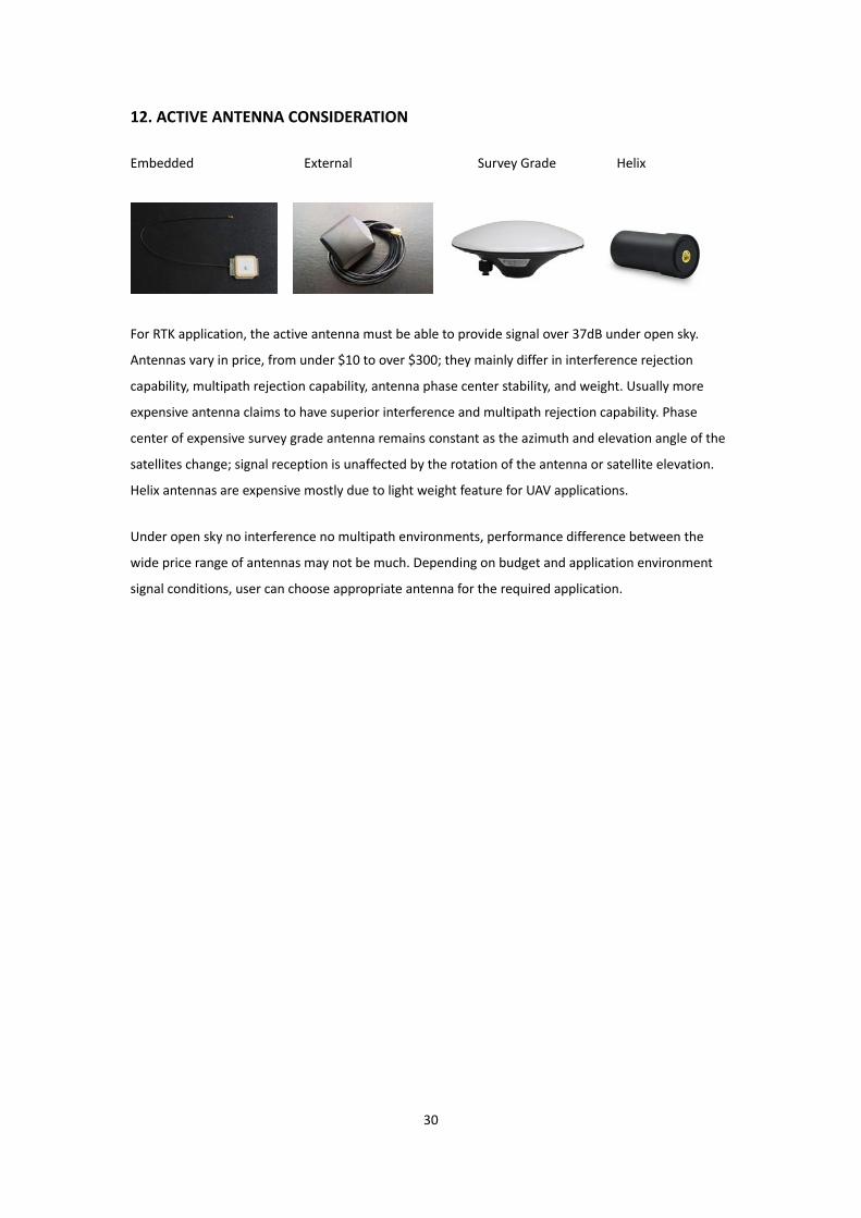
Embedded External Survey Grade Helix
For RTK application, the active antenna must be able to provide signal over 37dB under open sky.
Antennas vary in price, from under $10 to over $300; they mainly differ in interference rejection
capability, multipath rejection capability, antenna phase center stability, and weight. Usually more
expensive antenna claims to have superior interference and multipath rejection capability. Phase
center of expensive survey grade antenna remains constant as the azimuth and elevation angle of the
satellites change; signal reception is unaffected by the rotation of the antenna or satellite elevation.
Helix antennas are expensive mostly due to light weight feature for UAV applications.
Under open sky no interference no multipath environments, performance difference between the
wide price range of antennas may not be much. Depending on budget and application environment
signal conditions, user can choose appropriate antenna for the required application.

31
13. FIRMWARE UPDATE
When there is firmware update release, it’ll be made available on the NS‐HP‐GL web store product
page. Firmware for NS‐HP‐GL, NS‐HP‐GL‐5, NS‐HP‐GL‐5S, NS‐HP‐GL‐10, NS‐HP‐GL‐10S are
incompatible; user should update his/her NS‐HP‐GL with the correct firmware.
There are two 32bit RISC controllers inside NS‐HP‐GL module, one act as master, the other as slave.
Different firmware is used to program master and slave controllers. Firmware for master controller has
“master” in the filename. Firmware for slave controller has “slave” in the filename.
To update master controller firmware using GNSS Viewer:
1. Connect TX1 and RX1 to an UART‐to‐USB bridge breakout board for connecting to a Windows PC

32
2. Connect GNSS Viewer with NS‐HP‐GL using correct COM port and baud rate. Select the master
firmware. Click Download. After Download finishes it’ll restart.
3. Master firmware has default set to rover mode. If using NS‐HP‐GL as base, procedure for setting
up base mode and antenna position needs to be done again after firmware update,

33
To update slave controller firmware using GNSS Viewer:
1. Connect TX2 and RX2 to an UART‐to‐USB bridge breakout board for connecting to a Windows PC

34
2. Connect GNSS Viewer with NS‐HP‐GL using correct COM port and 57600 baud rate. Select the
slave firmware. Click Download. After Download finishes it’ll restart.
In case somehow the firmware in master or slave controller got corrupted and NS‐HP‐GL cannot
connect with GNSS Viewer:
1. Connect BOOT_SEL1 to GND to boot master controller from ROM code instead of Flash code,
recycle power by disconnect & reconnect USB, perform procedure to update master controller
firmware but using 4800 baud rate. After firmware updated, disconnect BOOT_SEL1 from GND.
2. Connect BOOT_SEL2 to GND to boot slave controller from ROM code instead of Flash code,
recycle power by disconnect & reconnect USB, perform procedure to update slave controller
firmware but using 9600 baud rate. After firmware updated, disconnect BOOT_SEL2 from GND.

35
14. POSSIBLE CONNECTION FOR QUADCOPTER APPLICATION
Pixhawk Rover Connection
Ground Base Connection

36
For the 3.3V Regulator in above figure, if you already have the UART‐to‐USB Adapter
breakout board from the web‐store freebie, you can modify as below adding a wire
connecting pin‐stick to capacitor (red wire) and have a 5V‐to‐3.3V LDO regulator to
use.

37
15. FAQ
Q1: Why I cannot receive RTK fix for a long time? My received signal is as below.
A1: NS‐HP‐GL require at least 7 satellites, signal level above 37dB, elevation angle
above 15 degrees, and good geometry to have position fix; more satellites the better.
Currently there is only 3 satellites with 37dB or higher signal, thus cannot have RTK
fix.
Keep antenna at least 10cm away from NS‐HP‐GL, farther the better, to avoid picking
up its radiated digital noise, signal level will be higher if placed at distance. 7cm x
7cm or larger metallic sheet (or tin foil) placed underneath the antenna could also
boost signal couple dB more.

38
CHANGE LOG
Version 0.3, September 30, 2017 1. Updated section 14 figures
Version 0.2, January 05, 2017 1. Updated section 1 on supported RTCM types 2. Updated section 6 to 9 on GNSS viewer configurations 3. Inserted base stream format into section 6 4. Inserted RTK reference static started position into section 7 5. Inserted section 10 on advanced moving base Version 0.1, August 4, 2016 1. Initial release The information provided is believed to be accurate and reliable. These materials are provided to customers and may be used for informational purposes only. No responsibility is assumed for errors or omissions in these materials, or for its use. Changes to specification can occur at any time without notice. These materials are provides “as is” without warranty of any kind, either expressed or implied, relating to sale and/or use including liability or warranties relating to fitness for a particular purpose, consequential or incidental damages, merchantability, or infringement of any patent, copyright or other intellectual property right. No warrant on the accuracy or completeness of the information, text, graphics or other items contained within these materials. No liability assumed for any special, indirect, incidental, or consequential damages, including without limitation, lost revenues or lost profits, which may result from the use of these materials. The product is not intended for use in medical, life-support devices, or applications involving potential risk of death, personal injury, or severe property damage in case of failure of the product.