Embed Size (px)
Citation preview
NSG 5500 AUTOMOTIVE TRAN-SIENT IMMUNITY GENERATOR
HARDWARE GUIDE
601-302E
NSG 5500 AUTOMOTIVE TRAN-SIENT IMMUNITY GENERATOR
HARDWARE GUIDE
3CONTENTS
1 Safety instructions 51.1 Classification of dangers 61.2 Warning symbols on the test system 61.3 Excess voltage category 71.4 Range of validity 71.5 SYSTEM STOP button 71.6 Safety of operation 81.7 Personnel 81.8 Responsibility for safety precaution 81.9 Safety regulations 81.10 Reduction of operational safety 91.11 As agreed use 91.12 General instructions 91.13 Installation 101.14 Test execution 111.15 Dangers concerning the generator 111.16 Dangers concerning the DUT 122 Installation 132.1 Checking the shipment 132.2 Delivery contents 132.3 Operating position 132.4 Line voltage connection and grounding 132.4.1 Mains voltage selector 142.5 Installation / set-up NSG 5500 172.6 Installation / set-up FT 5531 182.6.1 Test set-up 182.6.2 Parameter references 192.7 Installation / set-up LD 5505 and LD 5550 202.7.1 Test set-up 202.7.2 Parameter references 212.8 Installation / set-up MT 5511 222.8.1 Test set-up 222.8.2 Parameter references 232.9 Installation / set-up control unit (CTR) 242.9.1 Setting the IEEE address 242.9.1.1 IEEE address setting CTR 5500 242.9.1.2 IEEE address setting CTR 5501 252.9.2 Updating NSG 5500 firmware 252.9.2.1 Updating the firmware CTR 5500 262.9.2.2 Updating the firmware CTR 5501 262.9.2.3 Installation 262.9.2.4 Starting the loader 262.9.2.5 Startup error 282.9.2.6 Download operation 292.9.2.7 Downloading 302.9.2.8 Recovery 31
4
NSG 5500 Automotive transient immunity generator
3 Operation 333.1 General system overview 333.2 NSG 5500 Operation 343.2.1 Introduction 343.2.2 Powering up the system 353.2.3 NSG 5500 System overview 363.2.3.1 CDN 5500 - Power entry and battery switch 373.2.3.2 Control unit 403.2.3.3 HV-supply 413.2.3.4 System block diagram 423.2.3.5 External connection of pulse 4 amplifiers 433.2.4 Remote programming 443.2.5 External trigger and control signals 443.2.5.1 Start/stop signal 453.2.5.2 DUT FAIL signal 463.2.5.3 CRO trigger 463.2.6 RS 232 wiring diagram 473.2.6.1 Optical interface 473.3 FT 5531 Operation 483.3.1 Introduction 483.3.2 Block diagram 493.3.3 Tests with a coupling clamp 503.4 LD 5505 and LD 5550 Operation 523.4.1 Introduction 523.4.2 Block diagram 533.4.3 External output resistance (LD 5505 only) 533.5 MT 5511 Operation 543.5.1 Introduction 543.5.2 Block diagram 563.5.3 Transient diagram 564 Maintenance 574.1 Cleaning the equipment 574.2 Moving and storing the device 574.3 Protection 584.3.1 Magnetic circuit breaker 584.3.2 Fuses 594.4 Declaration of conformity CE 625 Technical Data 635.1 Technical specifications 635.1.1 NSG 5500 635.1.2 MT 5511 635.1.3 LD 5505 645.1.4 LD 5550 645.1.5 FT 5530 645.1.6 FT 5531 645.2 Measures and weight 655.3 Environmental Conditions 656 Addresses 66
51 SAFETY INSTRUCTIONS
These operating instructions form an integral part of the equipment and must be available to the operating personnel at all times. All the safety instructions and advice notes are to be observed.
DANGER! It is imperative that you read the following safety instructions and all safety ins-
tructions in the manuals of connected peripheral systems before installing and starting this test system for the fi rst time.
DANGER! The electrical and mechanical safety equipment must not be removed, put out of
operation or bypassed. Handle all safety equipment with care. If a safety device should be broken or is not working, the system must be put out of operation until the safety device is repaired or exchanged and fully in working order again.
DANGER! HAZARDOUS AREA! Connectors on the test equipment must not be touched!
Only connect and disconnect the DUT and/or fi xture when the “SYSTEM STOP“ button is pressed.
The equipment may only be operated within an area that is explicitly declared a «Test Floor» (with appropriate signs) and protected against improper access.
6
NSG 5500 Automotive transient immunity generator
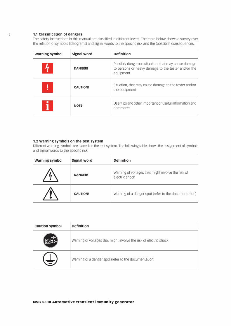
1.1 Classification of dangersThe safety instructions in this manual are classified in different levels. The table below shows a survey over the relation of symbols (ideograms) and signal words to the specific risk and the (possible) consequences.
Warning symbol Signal word Definition
DANGER!Possibly dangerous situation, that may cause damage to persons or heavy damage to the tester and/or the equipment.
CAUTION!Situation, that may cause damage to the tester and/or the equipment
NOTE!User tips and other important or useful information and comments
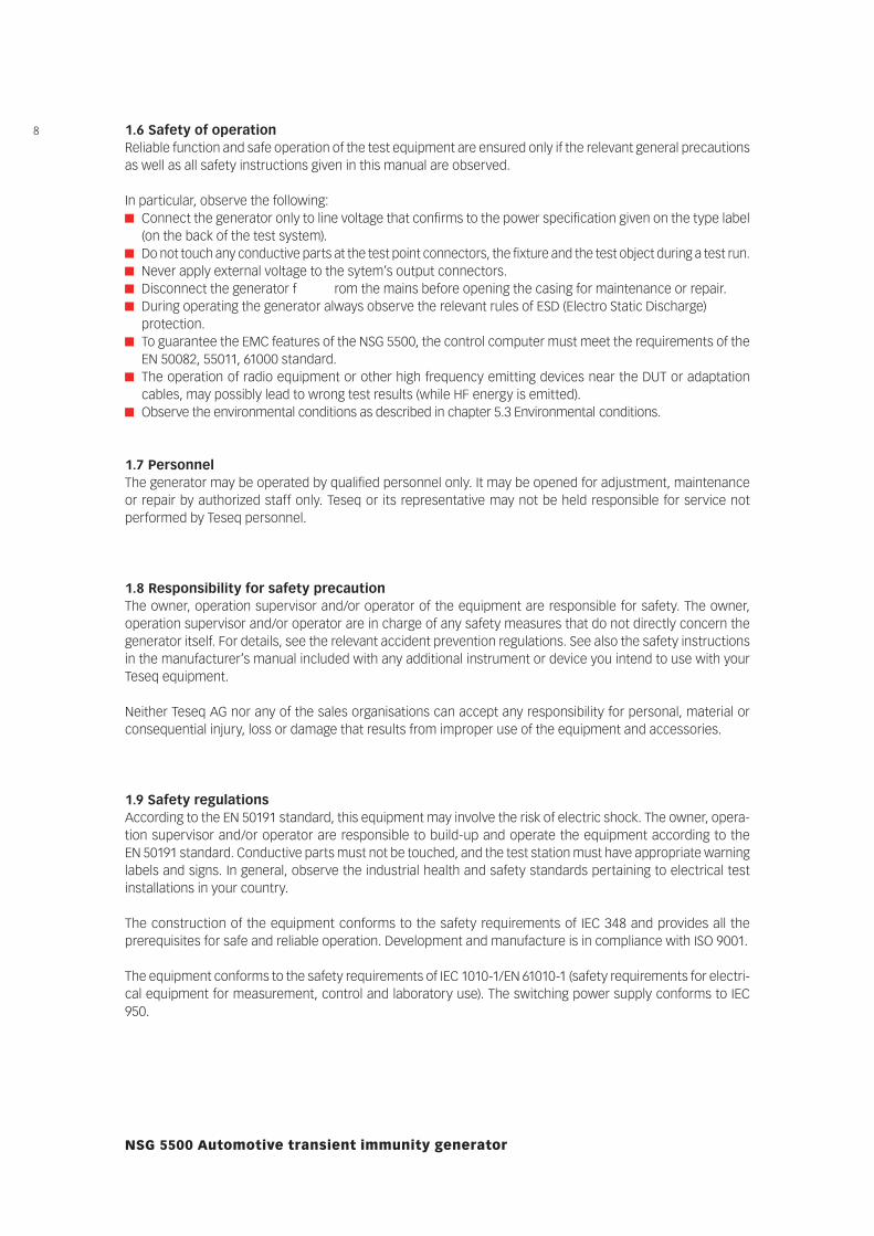
1.2 Warning symbols on the test systemDifferent warning symbols are placed on the test system. The following table shows the assignment of symbols and signal words to the specific risk.
Warning symbol Signal word Definition
DANGER!Warning of voltages that might involve the risk of electric shock
CAUTION! Warning of a danger spot (refer to the documentation)
Caution symbol Definition
Warning of voltages that might involve the risk of electric shock
Warning of a danger spot (refer to the documentation)

71.3 Excess voltage categoryThe test system NSG 5500, as described in this manual, is related to the excess voltage category II according IEC 60664.
1.4 Range of validityThese instructions are valid for the complete installation. Further safety regulations for components installed in this test system or additional installed devices are not suspended by these instructions.
1.5 SYSTEM STOP buttonPressing the “SYSTEM STOP” button (on the front panel of the FT 5531) or opening another safety circuit cuts the voltages that may involve electrical shock by touch.
DANGER! The “SYSTEM STOP“ button does not disconnect the test system from the line
voltage! If a danger for life, machine or the product occurs, the “SYSTEM STOP“ button
must be pressed! Thereby the test voltage in the DUT is disconnected.
NOTE! After resetting the “SYSTEM STOP“ button, the test system must be restarted
before continuing operation is possible.
8
NSG 5500 Automotive transient immunity generator
1.6 Safety of operationReliable function and safe operation of the test equipment are ensured only if the relevant general precautions as well as all safety instructions given in this manual are observed.
In particular, observe the following: Connect the generator only to line voltage that confirms to the power specification given on the type label
(on the back of the test system). Do not touch any conductive parts at the test point connectors, the fixture and the test object during a test run. Never apply external voltage to the sytem’s output connectors. Disconnect the generator f rom the mains before opening the casing for maintenance or repair. During operating the generator always observe the relevant rules of ESD (Electro Static Discharge)
protection. To guarantee the EMC features of the NSG 5500, the control computer must meet the requirements of the
EN 50082, 55011, 61000 standard. The operation of radio equipment or other high frequency emitting devices near the DUT or adaptation
cables, may possibly lead to wrong test results (while HF energy is emitted). Observe the environmental conditions as described in chapter 5.3 Environmental conditions.
1.7 PersonnelThe generator may be operated by qualified personnel only. It may be opened for adjustment, maintenance or repair by authorized staff only. Teseq or its representative may not be held responsible for service not performed by Teseq personnel.
1.8 Responsibility for safety precautionThe owner, operation supervisor and/or operator of the equipment are responsible for safety. The owner, operation supervisor and/or operator are in charge of any safety measures that do not directly concern the generator itself. For details, see the relevant accident prevention regulations. See also the safety instructions in the manufacturer’s manual included with any additional instrument or device you intend to use with your Teseq equipment.
Neither Teseq AG nor any of the sales organisations can accept any responsibility for personal, material or consequential injury, loss or damage that results from improper use of the equipment and accessories.
1.9 Safety regulationsAccording to the EN 50191 standard, this equipment may involve the risk of electric shock. The owner, opera-tion supervisor and/or operator are responsible to build-up and operate the equipment according to the EN 50191 standard. Conductive parts must not be touched, and the test station must have appropriate warning labels and signs. In general, observe the industrial health and safety standards pertaining to electrical test installations in your country.
The construction of the equipment conforms to the safety requirements of IEC 348 and provides all the prerequisites for safe and reliable operation. Development and manufacture is in compliance with ISO 9001.
The equipment conforms to the safety requirements of IEC 1010-1/EN 61010-1 (safety requirements for electri-cal equipment for measurement, control and laboratory use). The switching power supply conforms to IEC 950.
9All mains driven types of generators are equipped for high voltage working safety in accordance with VDE 0104.
The EMC compatibility has been tested with EN 61326 version 03/2002.
1.10 Reduction of operational safetyIf you have any reasons to suppose that the test equipment is not completely safe, you must shut it down and put it out of operation. Moreover, you must mark or label the equipment appropriately so it will not inadvertently be put into operation again. You should then call authorized service personnel for assistance.
1.11 As agreed useThe tester may be used exclusively for simulation of automotive EMC events.
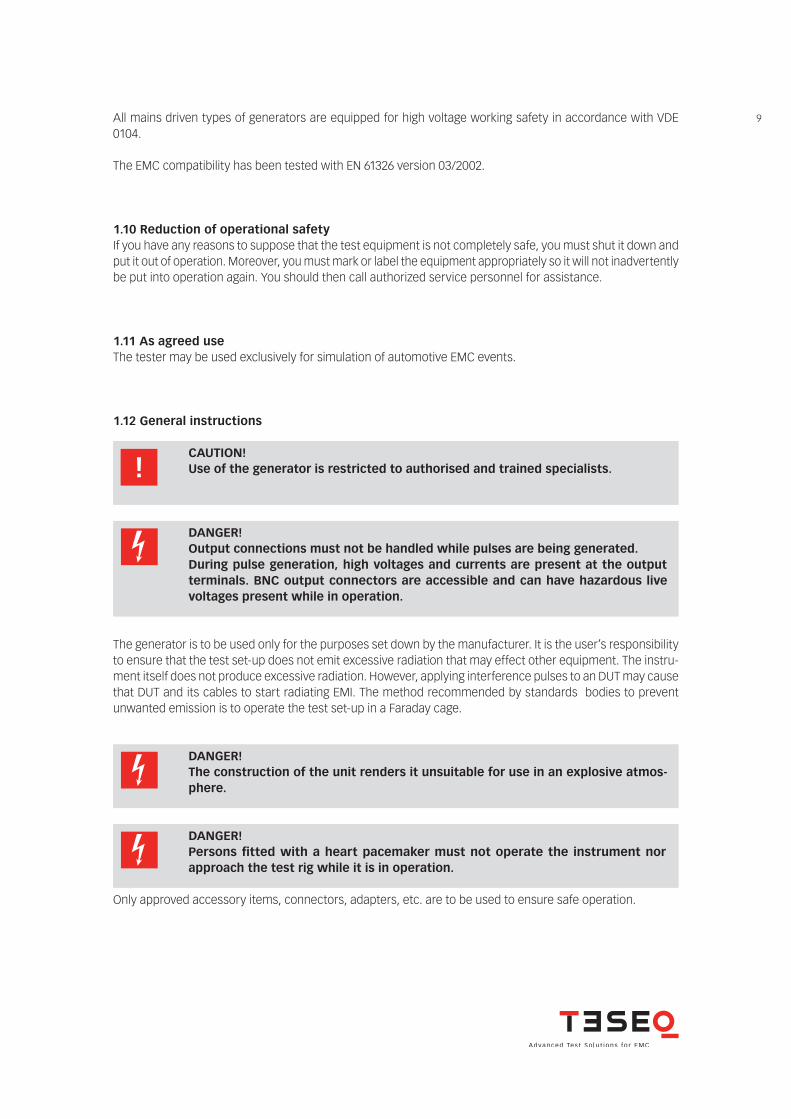
1.12 General instructions
The generator is to be used only for the purposes set down by the manufacturer. It is the user’s responsibility to ensure that the test set-up does not emit excessive radiation that may effect other equipment. The instru-ment itself does not produce excessive radiation. However, applying interference pulses to an DUT may cause that DUT and its cables to start radiating EMI. The method recommended by standards bodies to prevent unwanted emission is to operate the test set-up in a Faraday cage.
Only approved accessory items, connectors, adapters, etc. are to be used to ensure safe operation.
CAUTION! Use of the generator is restricted to authorised and trained specialists.
DANGER! Output connections must not be handled while pulses are being generated. During pulse generation, high voltages and currents are present at the output
terminals. BNC output connectors are accessible and can have hazardous live voltages present while in operation.
DANGER! The construction of the unit renders it unsuitable for use in an explosive atmos-
phere.
DANGER! Persons fitted with a heart pacemaker must not operate the instrument nor
approach the test rig while it is in operation.
10
NSG 5500 Automotive transient immunity generator
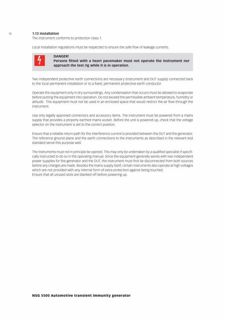
1.13 InstallationThe instrument conforms to protection class 1.
Local installation regulations must be respected to ensure the safe flow of leakage currents.
Two independent protective earth connections are necessary (instrument and DUT supply) connected back to the local permanent installation or to a fixed, permanent protective earth conductor.
Operate the equipment only in dry surroundings. Any condensation that occurs must be allowed to evaporate before putting the equipment into operation. Do not exceed the permissible ambient temperature, humidity or altitude. This equipment must not be used in an enclosed space that would restrict the air flow through the instrument.
Use only legally approved connectors and accessory items. The instrument must be powered from a mains supply that provides a properly earthed mains socket. Before the unit is powered up, check that the voltage selector on the instrument is set to the correct position.
Ensure that a reliable return path for the interference current is provided between the DUT and the generator. The reference ground plane and the earth connections to the instruments as described in the relevant test standard serve this purpose well.
The instruments must not in principle be opened. This may only be undertaken by a qualified specialist if specifi-cally instructed to do so in the operating manual. Since the equipment generally works with two independent power supplies for the generator and the DUT, the instrument must first be disconnected from both sources before any changes are made. Besides the mains supply itself, certain instruments also operate at high voltages which are not provided with any internal form of extra protection against being touched.Ensure that all unused slots are blanked off before powering up.
DANGER! Persons fitted with a heart pacemaker must not operate the instrument nor
approach the test rig while it is in operation.
111.14 Test executionThe test area must be so organised that no unauthorised persons have access during execution of a test.DUTs, together with their accessories and cables, are to be considered as being live during a test. The test generator must be stopped and the DUT supply interrupted before any work is carried out on the DUT. This can be implemented by pressing the “SYSTEM STOP” button.
DANGER! The DUT is to be tested only in a protective cage or under a hood which provides
protection against electric shock and all manner of other dangers pertaining to the particular DUT (see Dangers concerning the DUT).
CAUTION! The safety instructions concerning all the instruments and associated equipment
involved in the test rig are to be observed.
CAUTION! The configuration of the test rig is to be strictly in compliance with the methods
described in the relevant standard to ensure that the test is executed in a standard conforming manner.
1.15 Dangers concerning the generator
DANGER! Local burning, arcing, ignition of explosive gases.
DANGER! Danger from the resultant DUT supply current caused by a flashover or breakdown
resulting from the superimposed high voltage effects.
DANGER! Dangers from a disrupted DUT.
DANGER! Disturbance of unrelated electronics, telecommunications, navigational systems
and heart pacemakers through unnoticed radiation of high frequency energy.
In most test rigs the interference voltage is superimposed on the protective earth conductor of the DUT in accordance with the requirements of the test standard. Earth contacts or pins (e.g. in German and French connectors) as well as the DUT earth can hence be at a dangerous to touch voltage. The screws, too, in certain connectors are also linked to the protective earth conductor.
12
NSG 5500 Automotive transient immunity generator
1.16 Dangers concerning the DUTDUTs are often simply functional samples that have not previously been subjected to any safety tests. It can therefore happen that in some cases that the DUT is quickly damaged by internal overloads caused by the control electronics being disrupted or it may even start to burn.
DANGER! Internal disruption of the electronics can result in the interference voltage or the
DUT supply voltage being present on the DUT‘s housing.
CAUTION! As soon as the DUT shows signs of being disrupted the test must be stopped and
the power to the DUT switched off.
CAUTION! Electrical breakdown or arcing from and in plugged connections that are over-
stressed voltage-wise during the test.
DANGER! Explosion of electronic components with fire or fragmentation as a result of the
energy dissipated, e.g. from the resultant supply current or ignition of vaporised plastics materials.
CAUTION! Faulty behaviour by the DUT, e.g. robot device strikes out, temperature controller
fails, etc.
13
2.1 Checking the shipmentUpon receiving the shipment, fi rst check the packaging and outer equipment cover for visible damage. Also, check packaging and casings of peripherals (if you ordered any). Record in writing any defects which were possibly caused in transit. If the shipment shows damage or is not complete, immediately advise the shipping agency and/or your dealer.
2.2 Delivery contentsThe standard delivery contains the NSG 5500 with connection cables and the instruction manual. Optional modules are installed in the NSG 5500 if ordered. Possibly, there is also optional equipment, e.g. computer or printer.
2.3 Operating positionThe NSG 5500 must be placed in upright position fi rmly and securely during operation.
2.4 Line voltage connection and grounding
2 INSTALLATION
DANGER! Connect the NSG 5500 only to line voltage conforming to the power specifi cation
given on the type label.
If the grounding is interrupted inside or outside of the equipment, the NSG 5500 will become a source of danger. Additionally, the output of the device may not conform with the relevant test standards when the grounding of the power plug is interrupted. Carefully observe grounding precautions. The plug on the power cord may be replaced by qualifi ed personnel only.
The power input of the tester is located on the rear side of the NSG 5500 (see picture 3-4). The power input is secured by two 3.15 A time-lag fuses (220–240 V range) or two 6.3 A time-lag fuses (110–120 V range). For details, refer to chapter 4.3 Protection.
The power plug and outlet must have grounding contacts. When the NSG 5500 is brought from cold to warm environment, the ensuing condensation may bring about dangerous conditions.
DANGER! The NSG 5500 may only be switched on after all parts have acclimatized.
14
NSG 5500 Automotive transient immunity generator
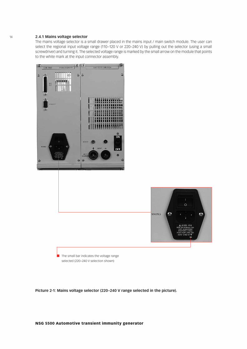
2.4.1 Mains voltage selectorThe mains voltage selector is a small drawer placed in the mains input / main switch module. The user can select the regional input voltage range (110–120 V or 220–240 V) by pulling out the selector (using a small screwdriver) and turning it. The selected voltage range is marked by the small arrow on the module that points to the white mark at the input connector assembly.
Picture 2-1: Mains voltage selector (220–240 V range selected in the picture).
The small bar indicates the voltage range
selected (220–240 V selection shown)
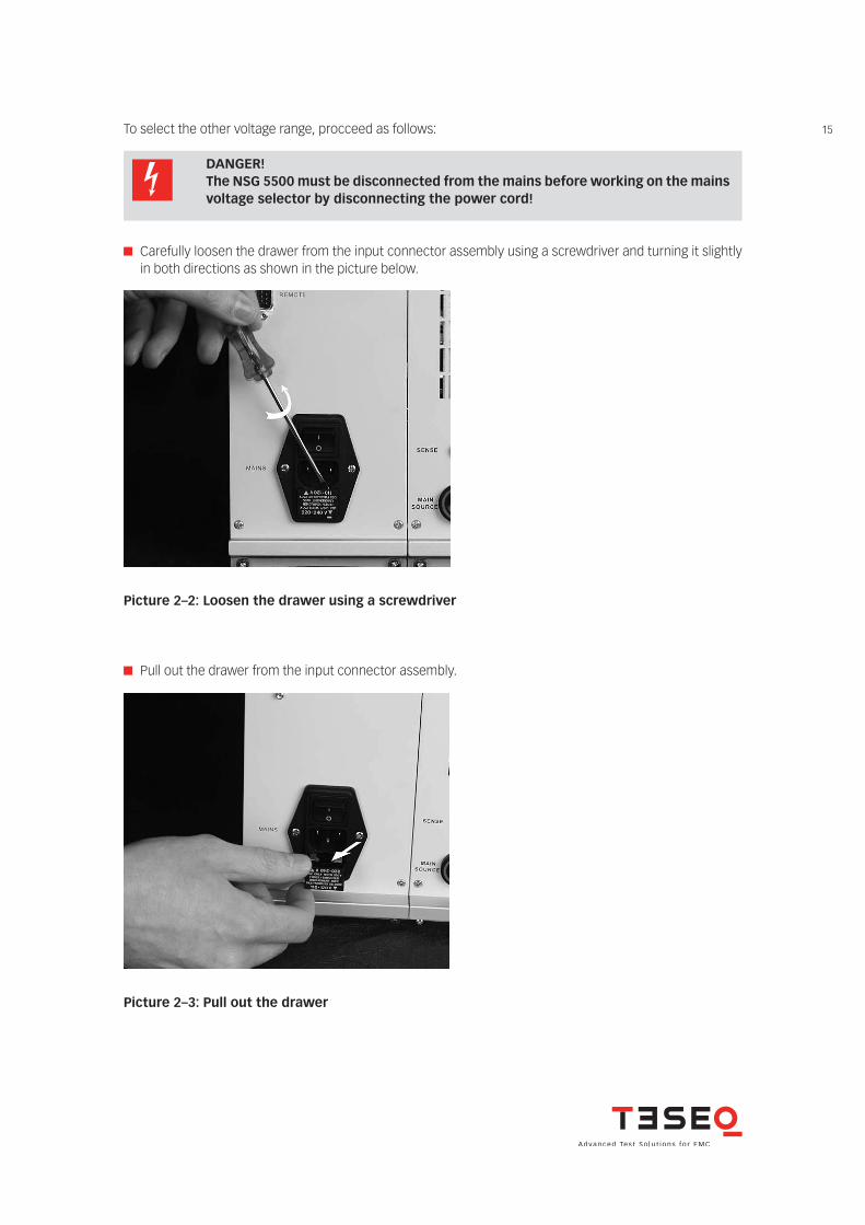
15To select the other voltage range, procceed as follows:
DANGER! The NSG 5500 must be disconnected from the mains before working on the mains
voltage selector by disconnecting the power cord!
Carefully loosen the drawer from the input connector assembly using a screwdriver and turning it slightly in both directions as shown in the picture below.
Picture 2–2: Loosen the drawer using a screwdriver
Pull out the drawer from the input connector assembly.
Picture 2–3: Pull out the drawer
16
NSG 5500 Automotive transient immunity generator
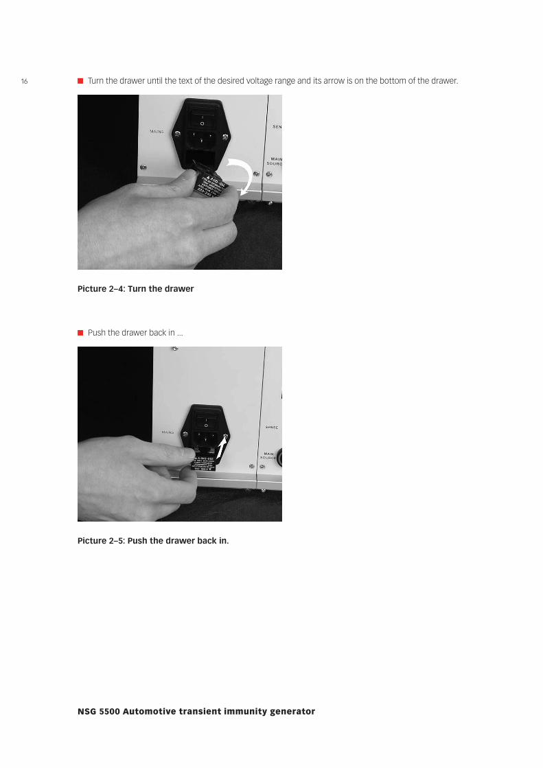
Turn the drawer until the text of the desired voltage range and its arrow is on the bottom of the drawer.
Picture 2–4: Turn the drawer
Push the drawer back in ...
Picture 2–5: Push the drawer back in.
17
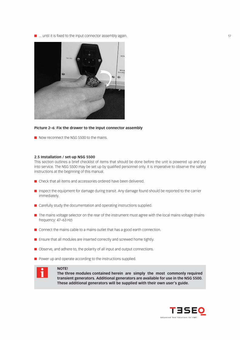
Now reconnect the NSG 5500 to the mains.
... until it is fixed to the input connector assembly again.
Picture 2–6: Fix the drawer to the input connector assembly
2.5 Installation / set-up NSG 5500This section outlines a brief checklist of items that should be done before the unit is powered up and put into service. The NSG 5500 may be set up by qualified personnel only. It is imperative to observe the safety instructions at the beginning of this manual.
Check that all items and accessories ordered have been delivered.
Inspect the equipment for damage during transit. Any damage found should be reported to the carrier immediately.
Carefully study the documentation and operating instructions supplied.
The mains voltage selector on the rear of the instrument must agree with the local mains voltage (mains frequency: 47–63 Hz)
Connect the mains cable to a mains outlet that has a good earth connection.
Ensure that all modules are inserted correctly and screwed home tightly.
Observe, and adhere to, the polarity of all input and output connections.
Power up and operate according to the instructions supplied.
NOTE! The three modules contained herein are simply the most commonly required
transient generators. Additional generators are available for use in the NSG 5500. These additional generators will be supplied with their own user’s guide.
18
NSG 5500 Automotive transient immunity generator
2.6 Installation / set-up FT 5531Check the instrument for any mechanical damage. Report any damage found to the carrier immediately.
Ensure that the power is turned off on the NSG 5500 mainframe and that the battery input is disconnected. Insert the cassette in the second slot from left and push in fully. Screw in the four retaining screws fully.
Turn on the mains input power on the NSG 5500 mainframe. After approximately a two second delay the power LED (red) on the FT 5531 generator should light.
Now the scope calibration setup shown in picture 2-7 should be connected and the output pulses should be quickly checked to ensure that they are of the correct form and shape. When pulses are generated the green LED (3a or 3b, whichever is selected) flashes as pulses are output.
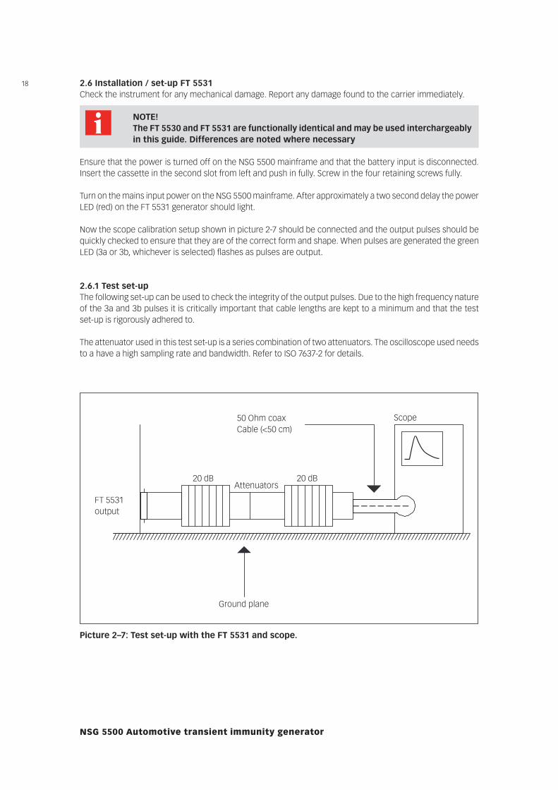
2.6.1 Test set-upThe following set-up can be used to check the integrity of the output pulses. Due to the high frequency nature of the 3a and 3b pulses it is critically important that cable lengths are kept to a minimum and that the test set-up is rigorously adhered to.
The attenuator used in this test set-up is a series combination of two attenuators. The oscilloscope used needs to a have a high sampling rate and bandwidth. Refer to ISO 7637-2 for details.
FT 5531output
Ground plane
Scope
20 dB 20 dBAttenuators
50 Ohm coaxCable (<50 cm)
Picture 2–7: Test set-up with the FT 5531 and scope.
NOTE! The FT 5530 and FT 5531 are functionally identical and may be used interchargeably
in this guide. Differences are noted where necessary
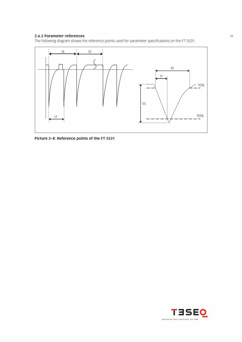
192.6.2 Parameter referencesThe following diagram shows the reference points used for parameter specifications on the FT 5531.
t1
t4 t5
td
tr
Vs
10%
90%
Picture 2–8: Reference points of the FT 5531
20
NSG 5500 Automotive transient immunity generator
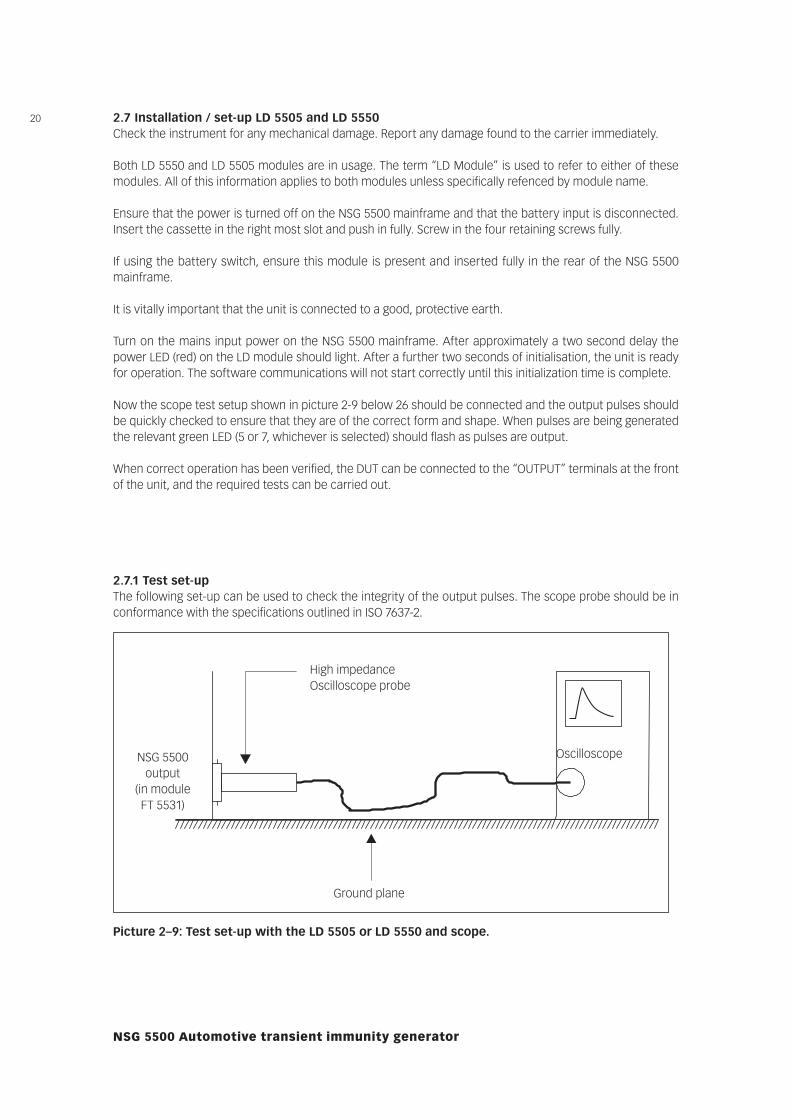
2.7.1 Test set-upThe following set-up can be used to check the integrity of the output pulses. The scope probe should be in conformance with the specifications outlined in ISO 7637-2.
Ground plane
High impedanceOscilloscope probe
OscilloscopeNSG 5500output
(in module FT 5531)
Picture 2–9: Test set-up with the LD 5505 or LD 5550 and scope.
2.7 Installation / set-up LD 5505 and LD 5550Check the instrument for any mechanical damage. Report any damage found to the carrier immediately.
Both LD 5550 and LD 5505 modules are in usage. The term “LD Module” is used to refer to either of these modules. All of this information applies to both modules unless specifically refenced by module name.
Ensure that the power is turned off on the NSG 5500 mainframe and that the battery input is disconnected. Insert the cassette in the right most slot and push in fully. Screw in the four retaining screws fully.
If using the battery switch, ensure this module is present and inserted fully in the rear of the NSG 5500 mainframe.
It is vitally important that the unit is connected to a good, protective earth.
Turn on the mains input power on the NSG 5500 mainframe. After approximately a two second delay the power LED (red) on the LD module should light. After a further two seconds of initialisation, the unit is ready for operation. The software communications will not start correctly until this initialization time is complete.
Now the scope test setup shown in picture 2-9 below 26 should be connected and the output pulses should be quickly checked to ensure that they are of the correct form and shape. When pulses are being generated the relevant green LED (5 or 7, whichever is selected) should flash as pulses are output.
When correct operation has been verified, the DUT can be connected to the “OUTPUT” terminals at the front of the unit, and the required tests can be carried out.
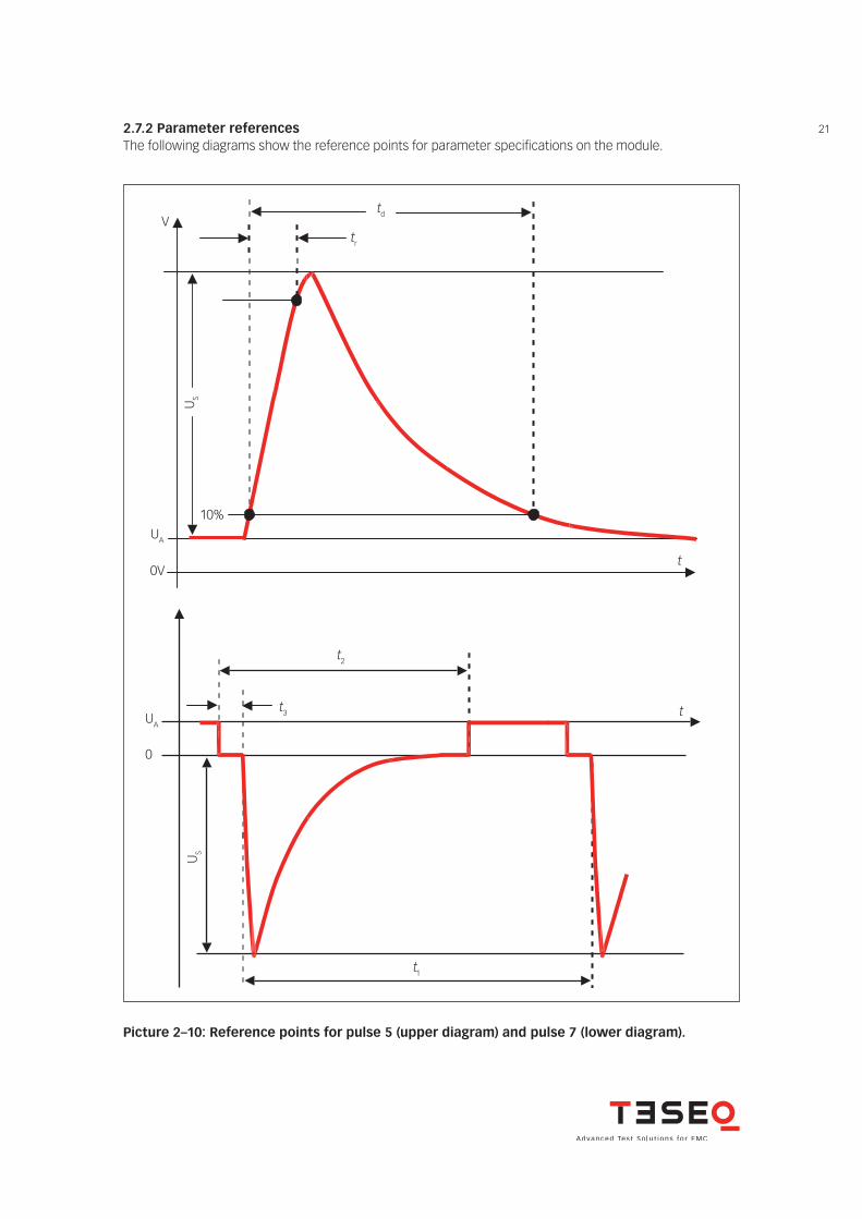
212.7.2 Parameter referencesThe following diagrams show the reference points for parameter specifications on the module.
td
Picture 2–10: Reference points for pulse 5 (upper diagram) and pulse 7 (lower diagram).
tr
US
10%
V
UA
0Vt
t2
t3 tUA
0
US
t1
22
NSG 5500 Automotive transient immunity generator
2.8 Installation / set-up MT 5511Check the instrument for any mechanical damage. Report any damage found to the carrier immediately.
Ensure that the power is turned off on the NSG 5500 mainframe and that the battery input is disconnected. Insert the cassette in the most left slot and push in fully. Screw in the four retaining screws fully. The battery switch is required, ensure that this module is present and inserted fully in the rear of the NSG 5500 main-frame.
It is vitally important that the unit mains power is connected to protective earth. Turn on the mains input power on the NSG 5500 mainframe. After approximately a two second delay the power LED (red) on the MT 5511 generator should light. After a further two-second initialisation period, the unit is ready for operation. The software communications will not start until this initialization time is complete.
The scope test set-up shown in picture 2-11 should be connected and the output pulses should be quickly checked to ensure that they are of the correct form and shape. As pulses are generated the “Fire” LED should light briefly.
The MT 5511 should be then verified in accordance with appendix D of ISO/DIS 7637-2:2004 or similar section of the applicable standard.
When correct operation has been verified, the DUT can be connected to the “OUTPUT” terminals at the front of the unit, and the required tests can be carried out.
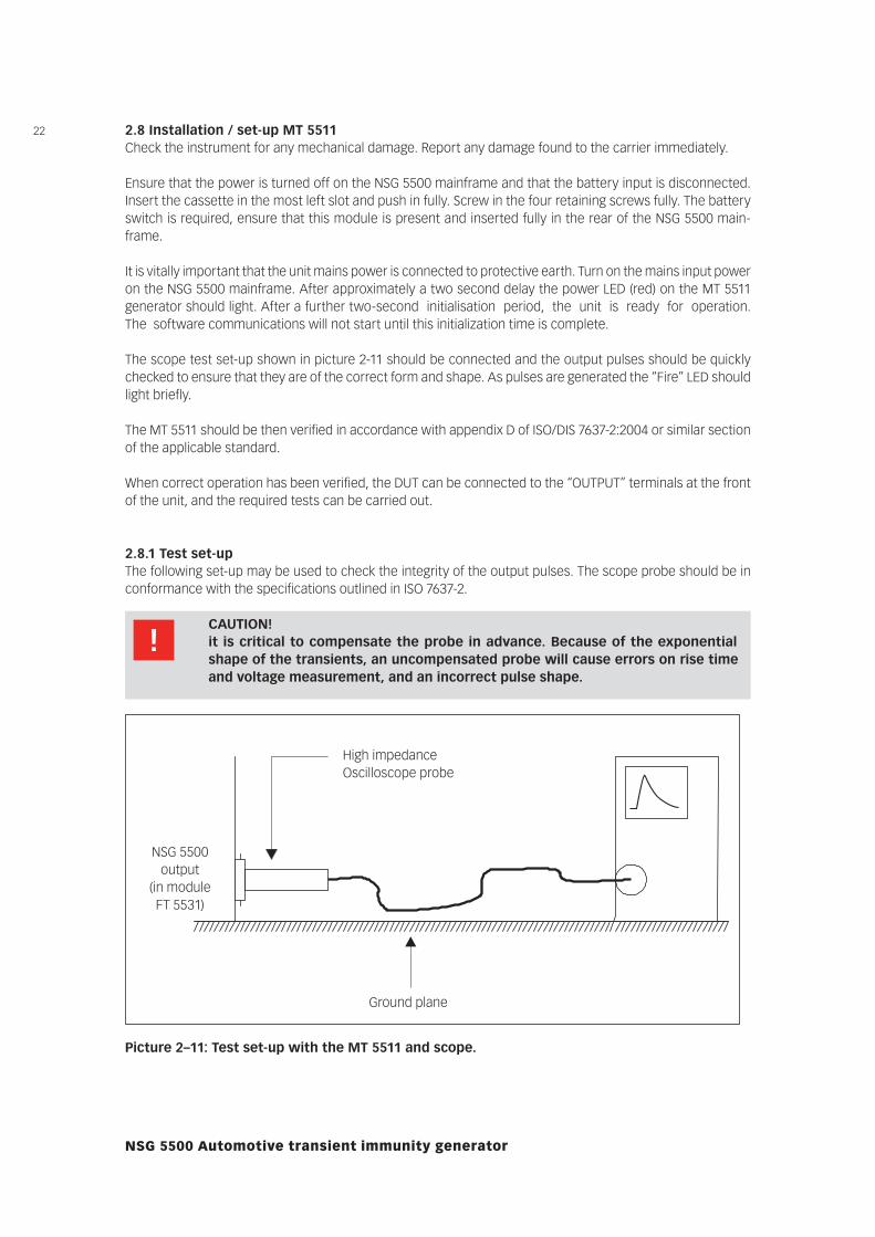
2.8.1 Test set-upThe following set-up may be used to check the integrity of the output pulses. The scope probe should be in conformance with the specifications outlined in ISO 7637-2.
CAUTION! it is critical to compensate the probe in advance. Because of the exponential
shape of the transients, an uncompensated probe will cause errors on rise time and voltage measurement, and an incorrect pulse shape.
Ground plane
High impedanceOscilloscope probe
NSG 5500output
(in module FT 5531)
Picture 2–11: Test set-up with the MT 5511 and scope.
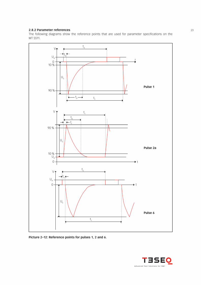
232.8.2 Parameter referencesThe following diagrams show the reference points that are used for parameter specifications on the MT 5511.
t
t2
t3
V
UA
010 %
90 %
US
td t1
Pulse 1
t1
td
tr
V
90 %
10 %UA
Pulse 2a
0
US
t
V
UA
0
US
t1
t
t3
t2
Pulse 6
Picture 2–12: Reference points for pulses 1, 2 and 6.

24
NSG 5500 Automotive transient immunity generator
2.9 Installation / set-up control unit (CTR)There are two controllers in circulation: The CTR 5500 and CTR 5501. The CTR 5501 has some small changes: it supports a new USB connection and has a new method of updating the firmware.
2.9.1 Setting the IEEE address2.9.1.1 IEEE address setting CTR 5500When communicating with the NSG 5500 via the IEEE 488 Interface it is necessary that the address set in the AutoStar comm setup screen corresponds with the IEEE 488 address set on the control unit.
A DIP switch array on the front panel of the control unit is used to set the NSG 5500 IEEE address. There may be five or six switches on this DIP switch, depending on the hardware version. Only the first five switches are used.
These first five switches correspond to the binary weighted address values 1, 2, 4, 8, and 16. The total sum of the values corresponding to the switches in the “ON” position is the IEEE address. For example, in the illustration below, the address set is 1 + 2 + 8 = 11.
ON
123456
1248
16
Picture 2–13: DIP switch array to set the NSG 5500 IEEE address.
NOTE! The address is read only at power on. Therefore, after changing the address
setting, the NSG 5500 must be powered off and then on to accept the new setting. The hardware is set at the factory to address 1. This is also reflected in the Auto-
Star setup.
CAUTION! The IEEE Bus has proven to be a very reliable control method in industrial environ-
ments. However, the CTR 5501 supports also USB control. Please note that USB can be affected by disturbances in typical EMC laboratories. For this reason, please use only the supplied USB cable.
Only cables confirming to the USB 2.0 standard and above are supported. Even so, in very noisy environments, the IEEE 488.2 connection is recommended.
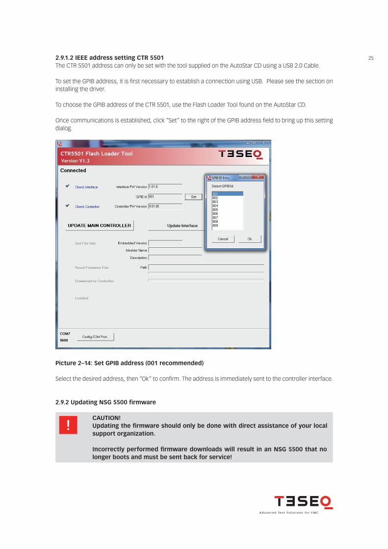
252.9.1.2 IEEE address setting CTR 5501The CTR 5501 address can only be set with the tool supplied on the AutoStar CD using a USB 2.0 Cable.
To set the GPIB address, it is fi rst necessary to establish a connection using USB. Please see the section on installing the driver.
To choose the GPIB address of the CTR 5501, use the Flash Loader Tool found on the AutoStar CD.
Once communications is established, click “Set“ to the right of the GPIB address fi eld to bring up this setting dialog.
Picture 2–14: Set GPIB address (001 recommended)
2.9.2 Updating NSG 5500 firmware
CAUTION! Updating the fi rmware should only be done with direct assistance of your local
support organization.
Incorrectly performed fi rmware downloads will result in an NSG 5500 that no longer boots and must be sent back for service!
Select the desired address, then “Ok“ to confi rm. The address is immediately sent to the controller interface.
26
NSG 5500 Automotive transient immunity generator
2.9.2.1 Updating the firmware CTR 5500The firmware of the CTR 5500 can be updated from within AutoStar. To update the CTR 5500, please see the applicable sections.
2.9.2.2 Updating the firmware CTR 5501The firmware of the CTR 5501 cannot be updated with AutoStar. To update the CTR 5501 firmware, please use the controller update tool found on the AutoStar CD.
Using the controller update tool (cut.exe) found on the installation CD, you can update the firmware. The firmware is located in the same directory as the controller update too.You may also choose the version to update if instructed to do so by service personnel.
2.9.2.3 InstallationNo specific installation procedure is required. Just copy the exe file into the desired working directory.
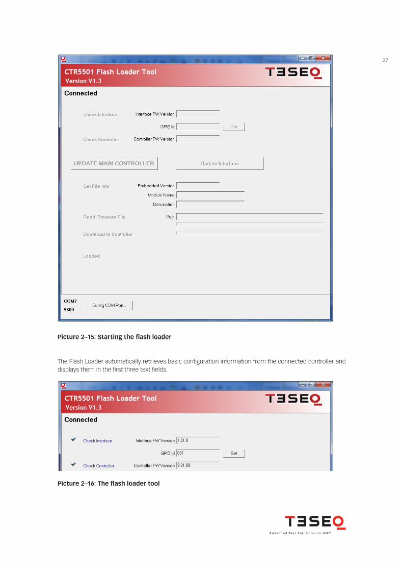
2.9.2.4 Starting the loaderAfter starting the application, the following screen appears. During the initialization period of about one second, the buttons for interacting with the controller are disabled.
CAUTION! You should only perform this step with the assistance of one of our worldwide
service representatives. Incorrectly performed firmware downloads will result in an NSG 5500 that no
longer boots and must be sent back for service!
27
Picture 2–15: Starting the flash loader
Picture 2–16: The flash loader tool
The Flash Loader automatically retrieves basic configuration information from the connected controller and displays them in the first three text fields.
28
NSG 5500 Automotive transient immunity generator
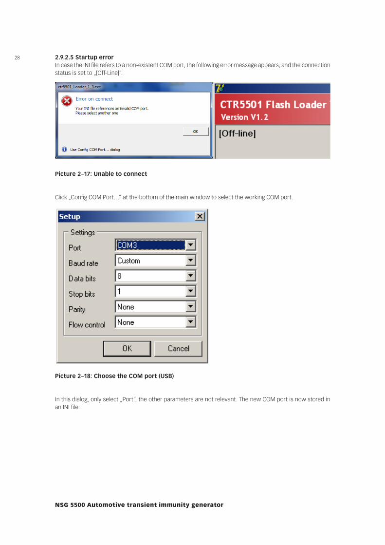
Picture 2–18: Choose the COM port (USB)
In this dialog, only select „Port“, the other parameters are not relevant. The new COM port is now stored in an INI file.
2.9.2.5 Startup errorIn case the INI file refers to a non-existent COM port, the following error message appears, and the connection status is set to „[Off-Line]“.
Picture 2–17: Unable to connect
Click „Config COM Port…“ at the bottom of the main window to select the working COM port.
29
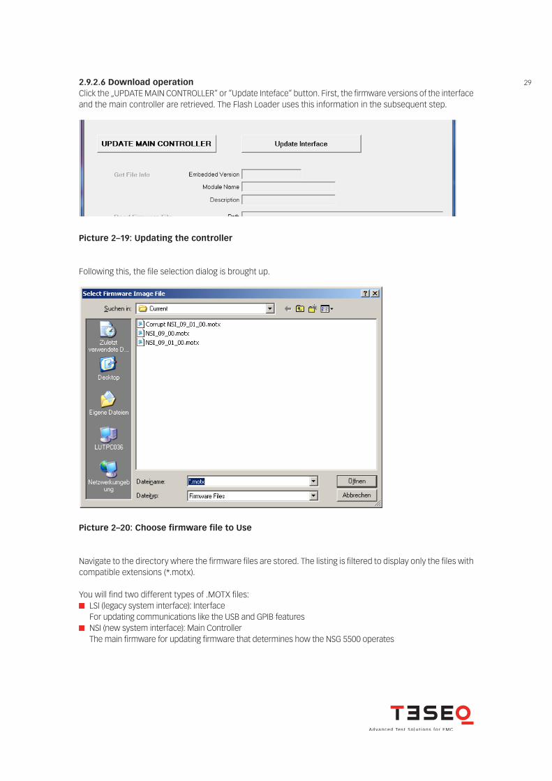
Following this, the file selection dialog is brought up.
Picture 2–19: Updating the controller
Picture 2–20: Choose firmware file to Use
Navigate to the directory where the firmware files are stored. The listing is filtered to display only the files with compatible extensions (*.motx).
You will find two different types of .MOTX files: LSI (legacy system interface): Interface
For updating communications like the USB and GPIB features NSI (new system interface): Main Controller
The main firmware for updating firmware that determines how the NSG 5500 operates
2.9.2.6 Download operationClick the „UPDATE MAIN CONTROLLER“ or “Update Inteface“ button. First, the firmware versions of the interface and the main controller are retrieved. The Flash Loader uses this information in the subsequent step.
30
NSG 5500 Automotive transient immunity generator
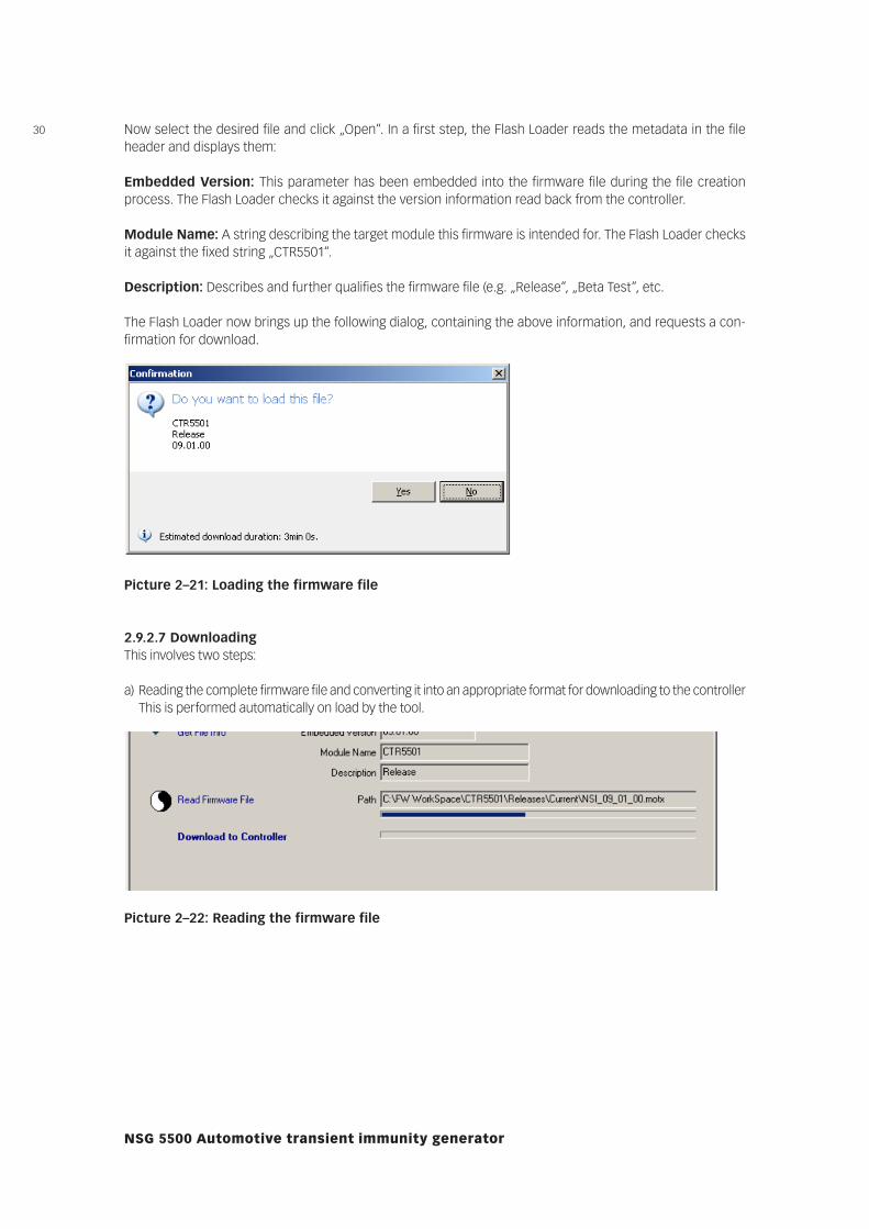
Now select the desired file and click „Open“. In a first step, the Flash Loader reads the metadata in the file header and displays them:
Embedded Version: This parameter has been embedded into the firmware file during the file creation process. The Flash Loader checks it against the version information read back from the controller.
Module Name: A string describing the target module this firmware is intended for. The Flash Loader checks it against the fixed string „CTR5501“.
Description: Describes and further qualifies the firmware file (e.g. „Release“, „Beta Test“, etc.
The Flash Loader now brings up the following dialog, containing the above information, and requests a con-firmation for download.
Picture 2–21: Loading the firmware file
2.9.2.7 DownloadingThis involves two steps:
a) Reading the complete firmware file and converting it into an appropriate format for downloading to the controller This is performed automatically on load by the tool.
Picture 2–22: Reading the firmware file
31
Picture 2–23: Downloading the firmware to the controller
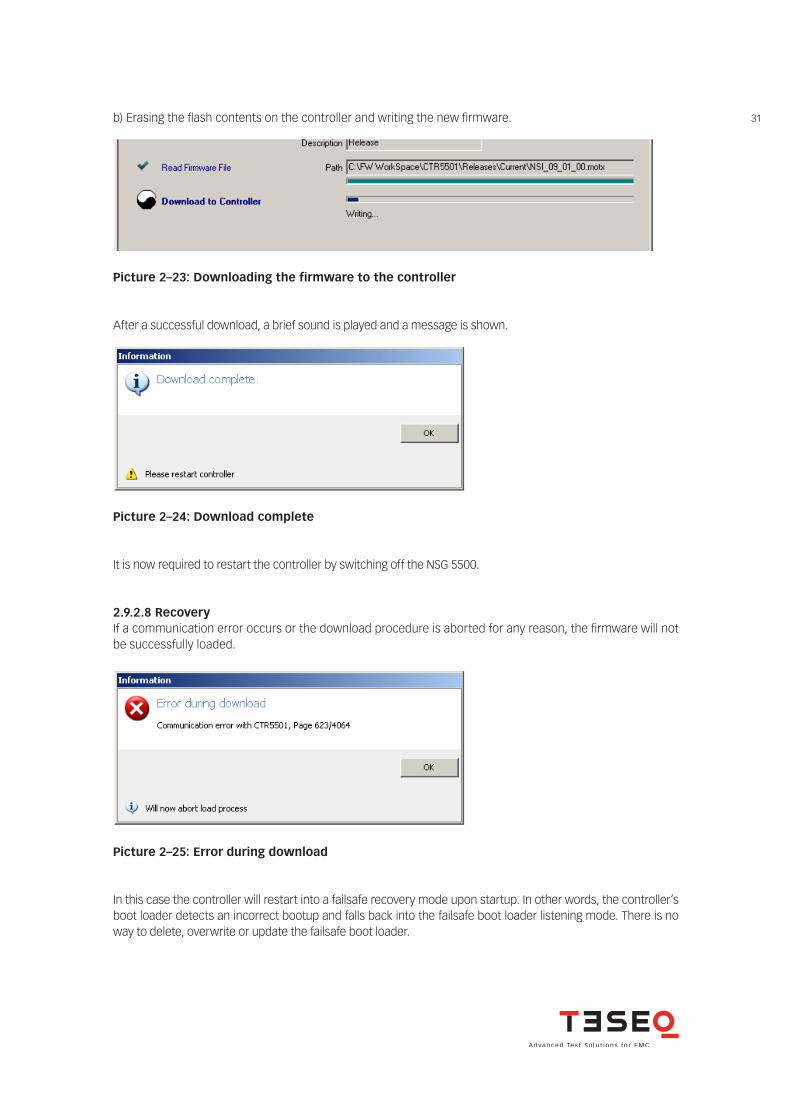
After a successful download, a brief sound is played and a message is shown.
Picture 2–24: Download complete
It is now required to restart the controller by switching off the NSG 5500.
2.9.2.8 RecoveryIf a communication error occurs or the download procedure is aborted for any reason, the firmware will not be successfully loaded.
Picture 2–25: Error during download
In this case the controller will restart into a failsafe recovery mode upon startup. In other words, the controller’s boot loader detects an incorrect bootup and falls back into the failsafe boot loader listening mode. There is no way to delete, overwrite or update the failsafe boot loader.
b) Erasing the flash contents on the controller and writing the new firmware.
32
NSG 5500 Automotive transient immunity generator
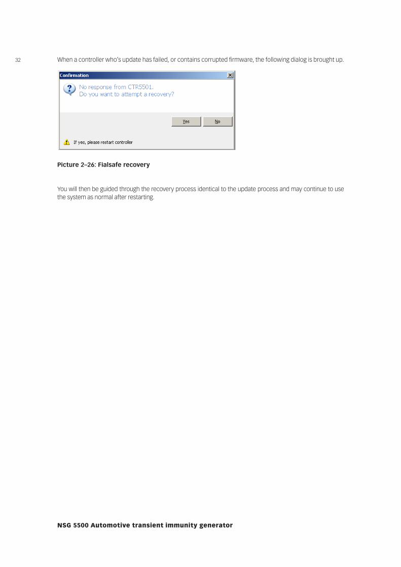
When a controller who’s update has failed, or contains corrupted firmware, the following dialog is brought up.
Picture 2–26: Fialsafe recovery
You will then be guided through the recovery process identical to the update process and may continue to use the system as normal after restarting.
33
3.1 General system overview
3 OPERATION
FT 5531
1 1 1 1
2
1 1
2
1NSG 5500-1 NSG 5500-2
INA 5025(Option)
Connected to „BUSEXP“ connector inpower entry unit
DUT and/or external couplers/ suppression networks etc.
P1, P2 Pulses connected to “EUT“ terminals
P3 Pulses connected to “EXT. PULSE“ BNC connector
Battery simulator PA 5840 (option)
connected to “MAIN source“ terminals in battery switch unit
INA 5026
2
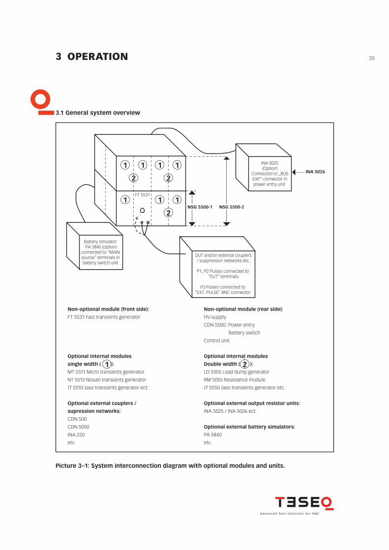
Picture 3–1: System interconnection diagram with optional modules and units.
Non-optional module (front side):
FT 5531 Fast transients generator
Optional internal modules
single width ( ):
MT 5511 Micro transients generator
NT 5512 NIssan transients generator
JT 5510 Jaso transients generator ect.
Optional external couplers /
supression networks:
CDN 500
CDN 5050
INA 220
etc.
Non-optional module (rear side):
HV-supply
CDN 5500: Power entry
Battery switch
Control unit
Optional internal modules
Double width ( ):
LD 5505 Load dump generator
RM 5055 Resistance module
JT 5550 Jaso transients generator etc.
Optional external output resistor units:
INA 5025 / INA 5026 ect.
Optional external battery simulators:
PA 5840
etc.
FT 5531
1 1 1 1
2
1 1
2
1NSG 5500-1 NSG 5500-2
INA 5025(Option)
Connected to „BUSEXP“ connector inpower entry unit
DUT and/or external couplers/ suppression networks etc.
P1, P2 Pulses connected to “EUT“ terminals
P3 Pulses connected to “EXT. PULSE“ BNC connector
Battery simulator PA 5840 (option)
connected to “MAIN source“ terminals in battery switch unit
INA 5026
2
34
NSG 5500 Automotive transient immunity generator
3.2 NSG 5500 Operation
3.2.1 Introduction
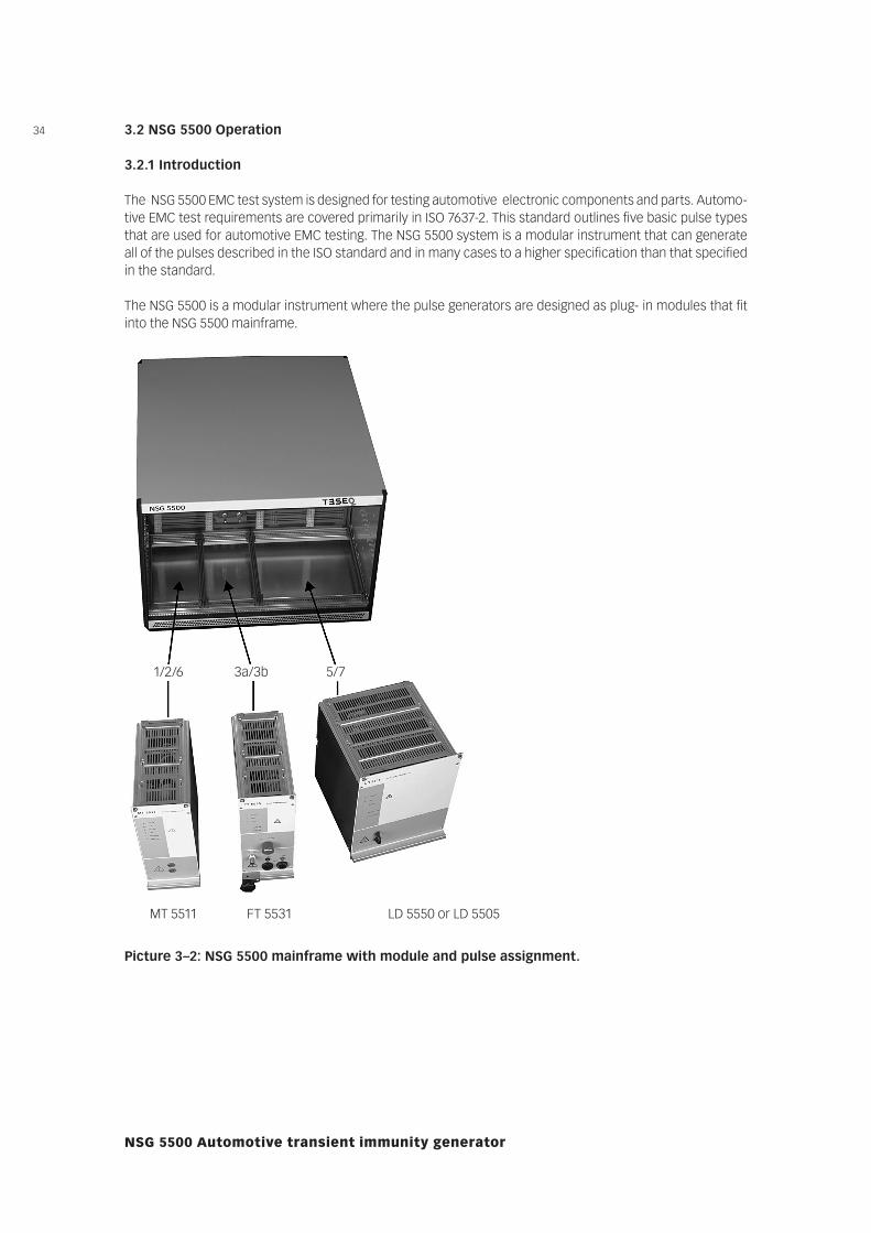
The NSG 5500 EMC test system is designed for testing automotive electronic components and parts. Automo-tive EMC test requirements are covered primarily in ISO 7637-2. This standard outlines five basic pulse types that are used for automotive EMC testing. The NSG 5500 system is a modular instrument that can generate all of the pulses described in the ISO standard and in many cases to a higher specification than that specified in the standard.
The NSG 5500 is a modular instrument where the pulse generators are designed as plug- in modules that fit into the NSG 5500 mainframe.
1/2/6 3a/3b 5/7
MT 5511 FT 5531 LD 5550 or LD 5505
Picture 3–2: NSG 5500 mainframe with module and pulse assignment.
35Due to the modular structure of the NSG 5500 you may configure a test system that provides only the pulse requirements that are required for your application by removing and installing additional modules as needed.
NOTE! Pulses of similar specification and energy requirements are usually housed in the
same plug-in unit. For example the ISO pulses 2a and 6 are all supplied within the same plug-in.
The NSG 5500 is fully programmable over USB or RS 232 and IEEE 488 interface bus. A Windows program «AutoStar» is available to provide full remote control via a PC computer. This program allows you to generate pulse sequences, including dynamic ramping, and to generate hardcopy printouts of the test results.
The main features of the NSG 5500 could be summarised as follows:
Modular construction, pulse modules plug into main chassis Exceeds specifications set out in the ISO, DIN and SAE standards Remote controllable via USB or RS 232 and IEEE 488 Internal multiplex bus system (all pulses available from the front of the FT 5531 plug-in) Compact construction, 12 inches high (30 cm) 19 inch rack mountable Windows software program provided DUT FAIL, START/STOP, TEST END, AND CRO trig signals available for interfacing with other test
equipment
3.2.2 Powering up the systemSwitch on the NSG 5500 by switching on the main switch on the rear side in the power entry unit.
CAUTION! The hardware requires at least 10 seconds to boot. Reliable software communi-
cations can not be established until the system is completely booted!
DANGER! When any Pulse 4 control is used, the power amplifier/battery simulator should
always be turned on last to assure safe and reliable control of the power amplifier/ battery simulator. Do not, under any circumstances, touch the outputs or connect any DUT to the outputs of the system during booting!
36
NSG 5500 Automotive transient immunity generator
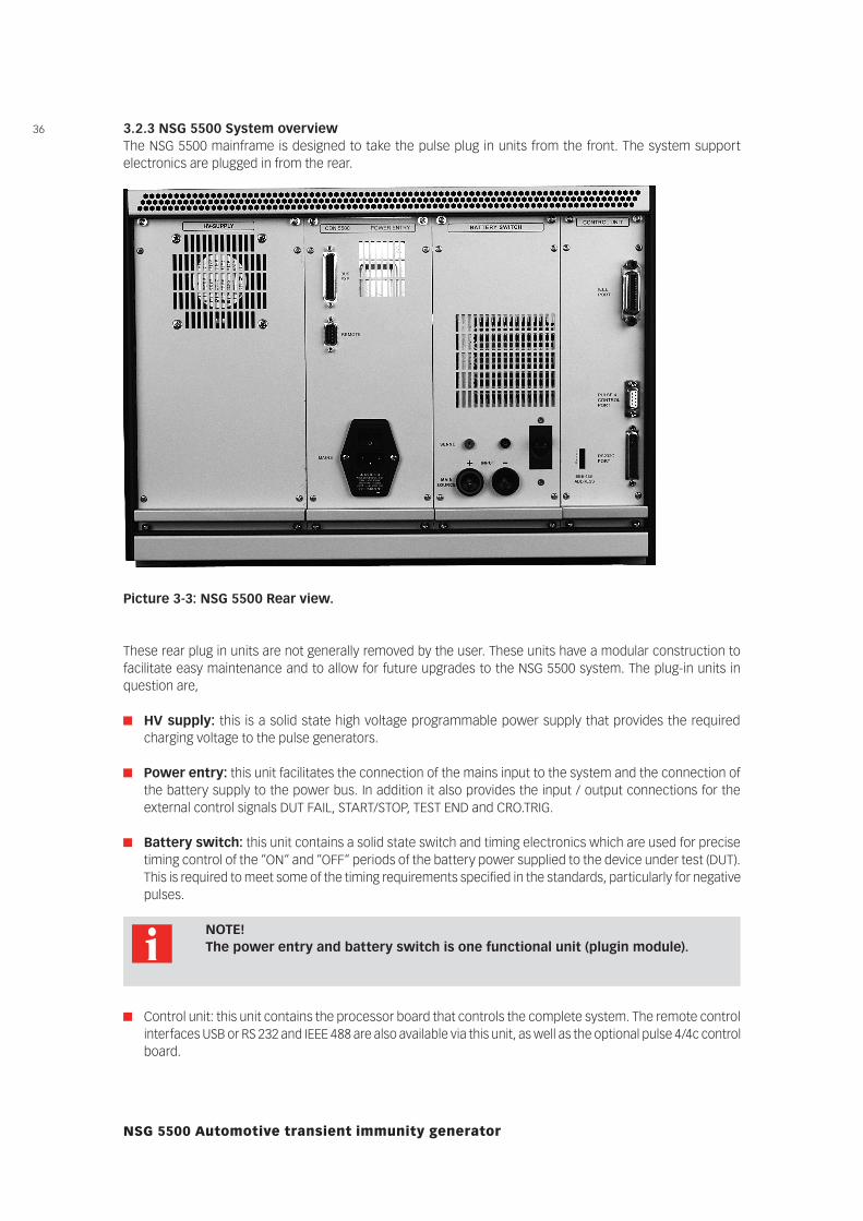
3.2.3 NSG 5500 System overviewThe NSG 5500 mainframe is designed to take the pulse plug in units from the front. The system support electronics are plugged in from the rear.
Picture 3-3: NSG 5500 Rear view.
These rear plug in units are not generally removed by the user. These units have a modular construction to facilitate easy maintenance and to allow for future upgrades to the NSG 5500 system. The plug-in units in question are,
HV supply: this is a solid state high voltage programmable power supply that provides the required charging voltage to the pulse generators.
Power entry: this unit facilitates the connection of the mains input to the system and the connection of the battery supply to the power bus. In addition it also provides the input / output connections for the external control signals DUT FAIL, START/STOP, TEST END and CRO.TRIG.
Battery switch: this unit contains a solid state switch and timing electronics which are used for precise timing control of the “ON“ and “OFF“ periods of the battery power supplied to the device under test (DUT). This is required to meet some of the timing requirements specified in the standards, particularly for negative pulses.
NOTE! The power entry and battery switch is one functional unit (plugin module).
Control unit: this unit contains the processor board that controls the complete system. The remote control interfaces USB or RS 232 and IEEE 488 are also available via this unit, as well as the optional pulse 4/4c control board.
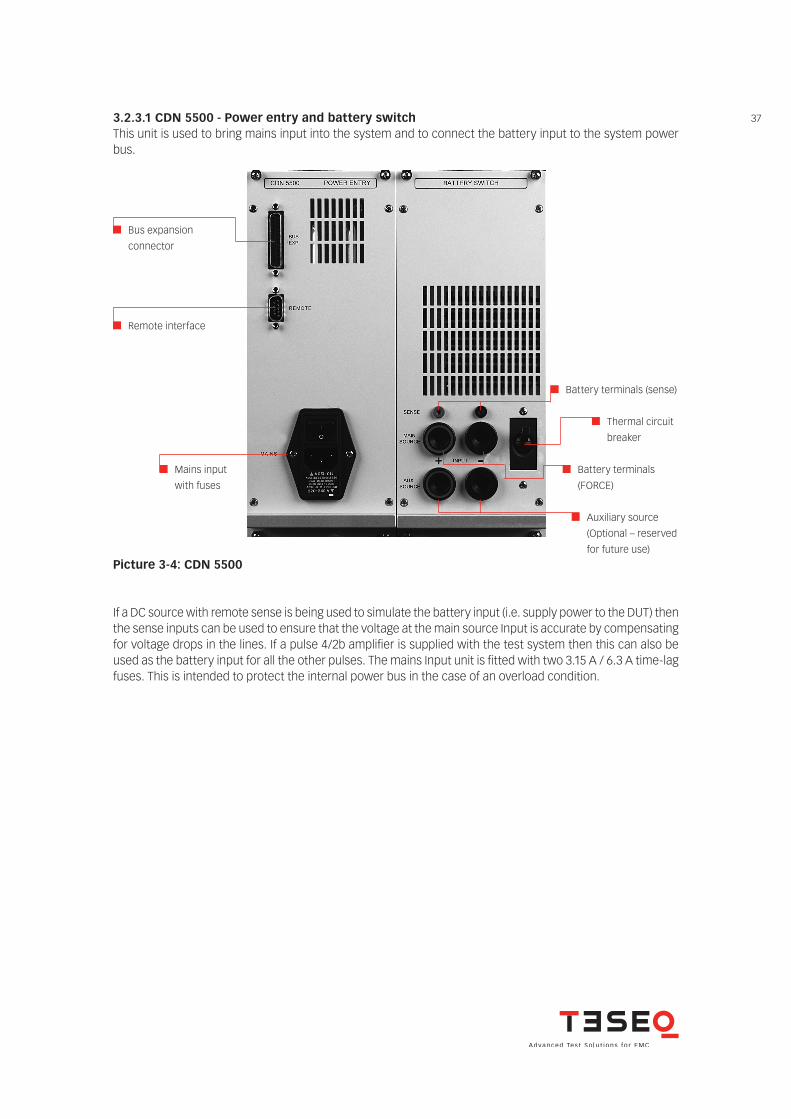
373.2.3.1 CDN 5500 - Power entry and battery switchThis unit is used to bring mains input into the system and to connect the battery input to the system power bus.
Bus expansion
connector
Remote interface
Mains input
with fuses
Auxiliary source
(Optional – reserved
for future use)
Battery terminals (sense)
Thermal circuit
breaker
Battery terminals
(FORCE)
Picture 3-4: CDN 5500
If a DC source with remote sense is being used to simulate the battery input (i.e. supply power to the DUT) then the sense inputs can be used to ensure that the voltage at the main source Input is accurate by compensating for voltage drops in the lines. If a pulse 4/2b amplifier is supplied with the test system then this can also be used as the battery input for all the other pulses. The mains Input unit is fitted with two 3.15 A / 6.3 A time-lag fuses. This is intended to protect the internal power bus in the case of an overload condition.
38
NSG 5500 Automotive transient immunity generator
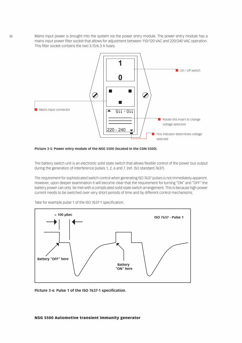
Mains input power is brought into the system via the power entry module. The power entry module has a mains input power filter socket that allows for adjustment between 110/120 VAC and 220/240 VAC operation. This filter socket contains the two 3.15/6.3 A fuses.
220 - 240
110 - 115
1
0
The battery switch unit is an electronic solid state switch that allows flexible control of the power bus output during the generation of interference pulses 1, 2, 6 and 7. (ref. ISO standard 7637).
The requirement for sophisticated switch control when generating ISO 7637 pulses is not immediately apparent. However, upon deeper examination it will become clear that the requirement for turning “ON“ and “OFF“ the battery power can only be met with a complicated solid state switch arrangement. This is because high power current needs to be switched over very short periods of time and by different control mechanisms.
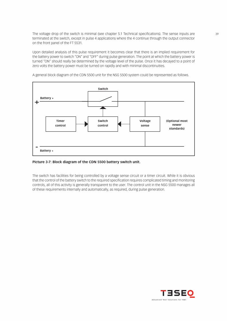
Take for example pulse 1 of the ISO 7637-1 specification.
Mains input connector
On / off switch
Rotate this Insert to change
voltage selection
This indicator determines voltage
selected
Picture 3-5: Power entry module of the NSG 5500 (located in the CDN 5500).
< 100 µSec
Battery “OFF“ here
Battery “ON“ here
ISO 7637 - Pulse 1
Picture 3-6: Pulse 1 of the ISO 7637-1 specification.
39The voltage drop of the switch is minimal (see chapter 5.1 Technical specifications). The sense inputs are terminated at the switch, except in pulse 4 applications where the 4 continue through the output connector on the front panel of the FT 5531.
Upon detailed analysis of this pulse requirement it becomes clear that there is an implied requirement for the battery power to switch “ON“ and “OFF“ during pulse generation. The point at which the battery power is turned “ON“ should really be determined by the voltage level of the pulse. Once it has decayed to a point of zero volts the battery power must be turned on rapidly and with minimal discontinuities.
A general block diagram of the CDN 5500 unit for the NSG 5500 system could be represented as follows.
+
-
Battery +
Timer
control
Switch
control
Voltage
sense
Battery +
(Optional most newer
standards)
Switch
Picture 3-7: Block diagram of the CDN 5500 battery switch unit.
The switch has facilities for being controlled by a voltage sense circuit or a timer circuit. While it is obvious that the control of the battery switch to the required specification requires complicated timing and monitoring controls, all of this activity is generally transparent to the user. The control unit in the NSG 5500 manages all of these requirements internally and automatically, as required, during pulse generation.
40
NSG 5500 Automotive transient immunity generator
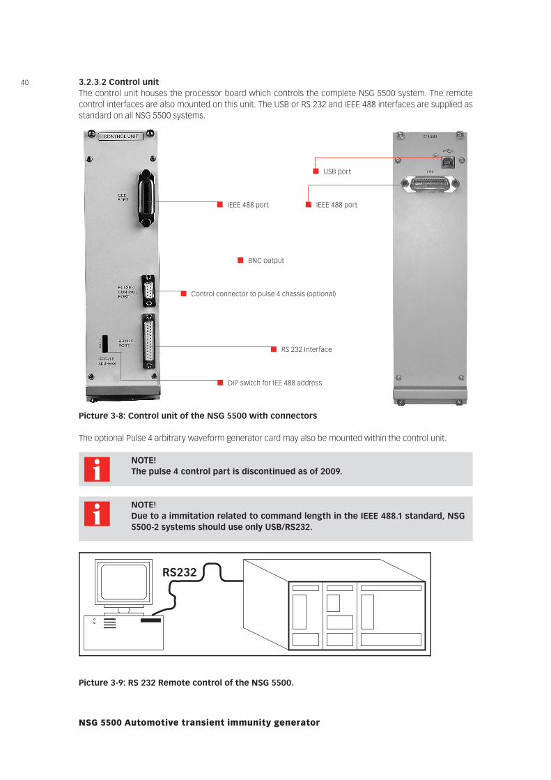
3.2.3.2 Control unitThe control unit houses the processor board which controls the complete NSG 5500 system. The remote control interfaces are also mounted on this unit. The USB or RS 232 and IEEE 488 interfaces are supplied as standard on all NSG 5500 systems.
IEEE 488 port
Control connector to pulse 4 chassis (optional)
RS 232 Interface
DIP switch for IEE 488 address
The optional Pulse 4 arbitrary waveform generator card may also be mounted within the control unit.
Picture 3-8: Control unit of the NSG 5500 with connectors
NOTE! The pulse 4 control part is discontinued as of 2009.
NOTE! Due to a immitation related to command length in the IEEE 488.1 standard, NSG
5500-2 systems should use only USB/RS232.
RS232
IEEE Interface(s)
IEEE
Picture 3-9: RS 232 Remote control of the NSG 5500.
BNC output
IEEE 488 port
USB port
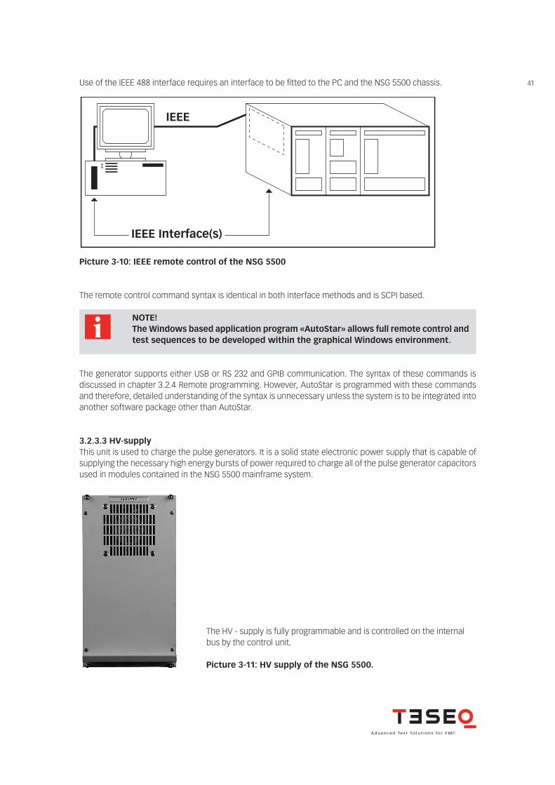
41Use of the IEEE 488 interface requires an interface to be fitted to the PC and the NSG 5500 chassis.
RS232
IEEE Interface(s)
IEEE
Picture 3-10: IEEE remote control of the NSG 5500
The remote control command syntax is identical in both interface methods and is SCPI based.
NOTE! The Windows based application program «AutoStar» allows full remote control and
test sequences to be developed within the graphical Windows environment.
The generator supports either USB or RS 232 and GPIB communication. The syntax of these commands is discussed in chapter 3.2.4 Remote programming. However, AutoStar is programmed with these commands and therefore, detailed understanding of the syntax is unnecessary unless the system is to be integrated into another software package other than AutoStar.
3.2.3.3 HV-supplyThis unit is used to charge the pulse generators. It is a solid state electronic power supply that is capable of supplying the necessary high energy bursts of power required to charge all of the pulse generator capacitors used in modules contained in the NSG 5500 mainframe system.
The HV - supply is fully programmable and is controlled on the internal bus by the control unit.
Picture 3-11: HV supply of the NSG 5500.
42
NSG 5500 Automotive transient immunity generator
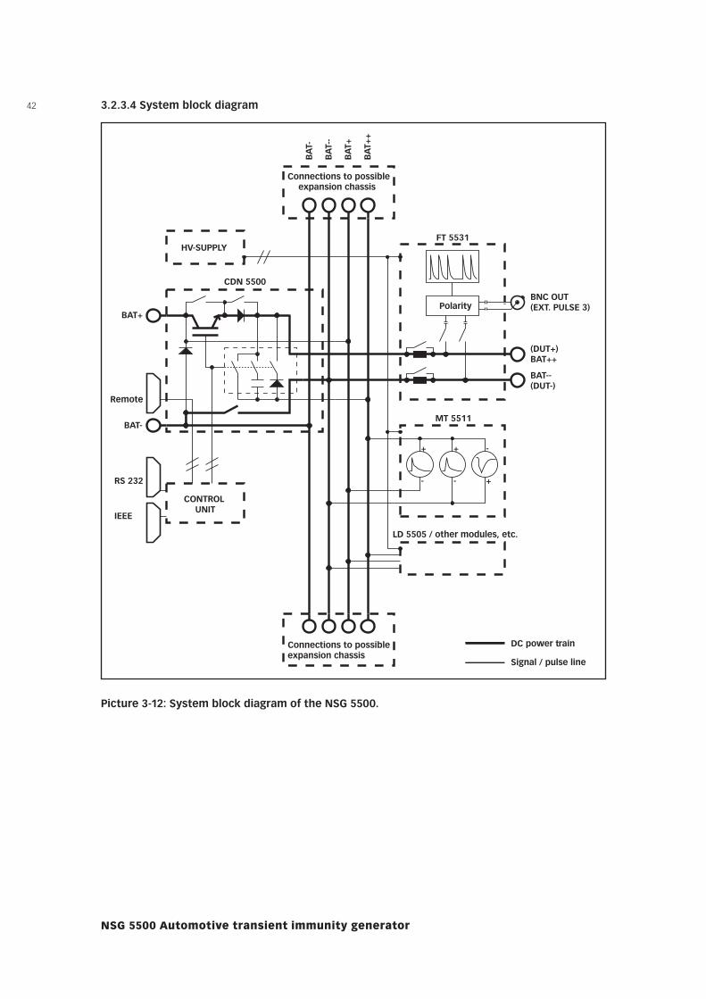
3.2.3.4 System block diagram
CDN 5500
CONTROL UNIT
HV-SUPPLY
Polarity
FT 5531
MT 5511
LD 5505 / other modules, etc.
Connections to possible expansion chassis
RS 232
IEEE
Connections to possible expansion chassis
(DUT+) BAT++
BAT-- (DUT-)
BNC OUT (EXT. PULSE 3)
BA
T-
BA
T--
BA
T+
BA
T++
BAT+
BAT-
Remote
-
+
-
+
+
-
DC power train
Signal / pulse line
Picture 3-12: System block diagram of the NSG 5500.
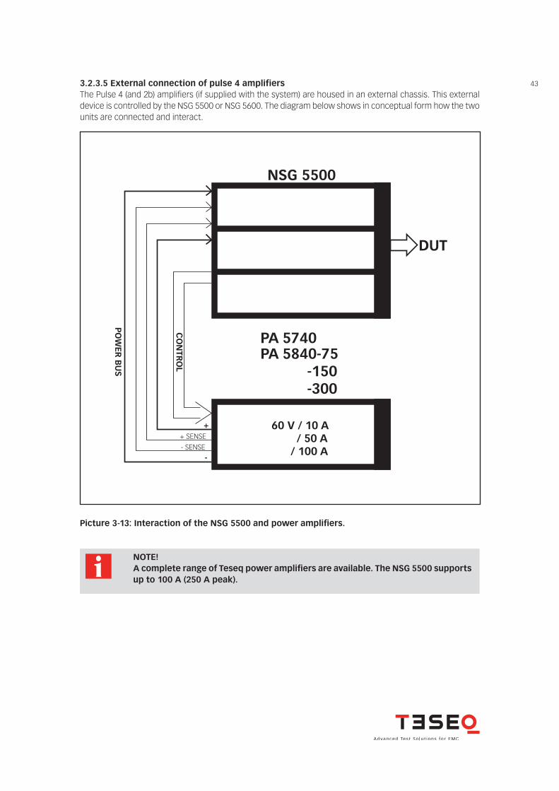
433.2.3.5 External connection of pulse 4 amplifiersThe Pulse 4 (and 2b) amplifiers (if supplied with the system) are housed in an external chassis. This external device is controlled by the NSG 5500 or NSG 5600. The diagram below shows in conceptual form how the two units are connected and interact.
NSG 5500
PA 5840-75 PA 5740
-150 -300
CO
NTR
OL
+
-
+ SENSE- SENSE
PO
WER
BU
S
60 V / 10 A / 50 A
/ 100 A
DUT
Picture 3-13: Interaction of the NSG 5500 and power amplifiers.
NOTE! A complete range of Teseq power amplifiers are available. The NSG 5500 supports
up to 100 A (250 A peak).
44
NSG 5500 Automotive transient immunity generator
3.2.4 Remote programmingA remote programming tools are available for advanced users who wish to program for their own special needs.
CAUTION! These commands are for advanced users only!
The examples contained therein are generally for users who choose to write their own test software. Teseq can not be held responsible for improper use of these commands and/or syntax.
Please refer to the AutoStar communication logs during use for a complete under-standing of the use of these commands.
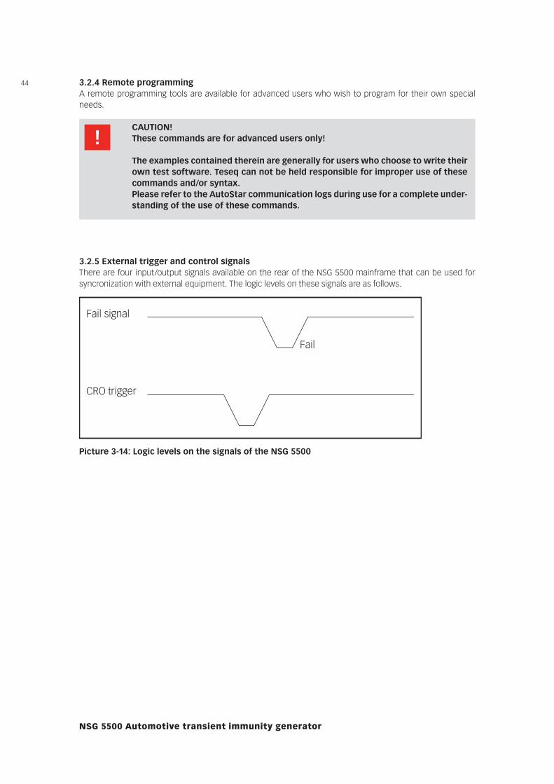
3.2.5 External trigger and control signalsThere are four input/output signals available on the rear of the NSG 5500 mainframe that can be used for syncronization with external equipment. The logic levels on these signals are as follows.
Fail signal
CRO trigger
Fail
Picture 3-14: Logic levels on the signals of the NSG 5500
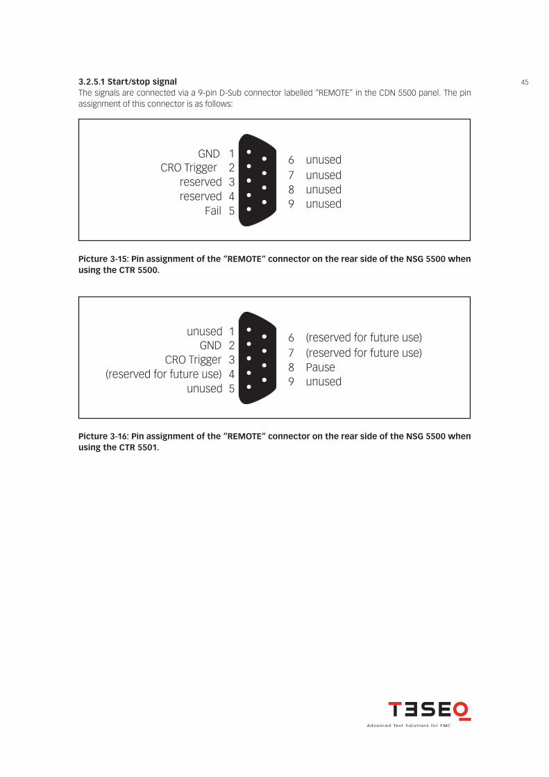
453.2.5.1 Start/stop signalThe signals are connected via a 9-pin D-Sub connector labelled “REMOTE“ in the CDN 5500 panel. The pin assignment of this connector is as follows:
GNDCRO Trigger
reservedreserved
Fail
12345
6789
unusedunusedunusedunused
1K+5 V
GNDPin 1
Pin 4
unusedGND
CRO Trigger(reserved for future use)
unused
12345
6789
(reserved for future use)(reserved for future use)Pauseunused
1K+5 V
GNDPin 1
Pin 4
Picture 3-15: Pin assignment of the “REMOTE“ connector on the rear side of the NSG 5500 when using the CTR 5500.
Picture 3-16: Pin assignment of the “REMOTE“ connector on the rear side of the NSG 5500 when using the CTR 5501.
46
NSG 5500 Automotive transient immunity generator
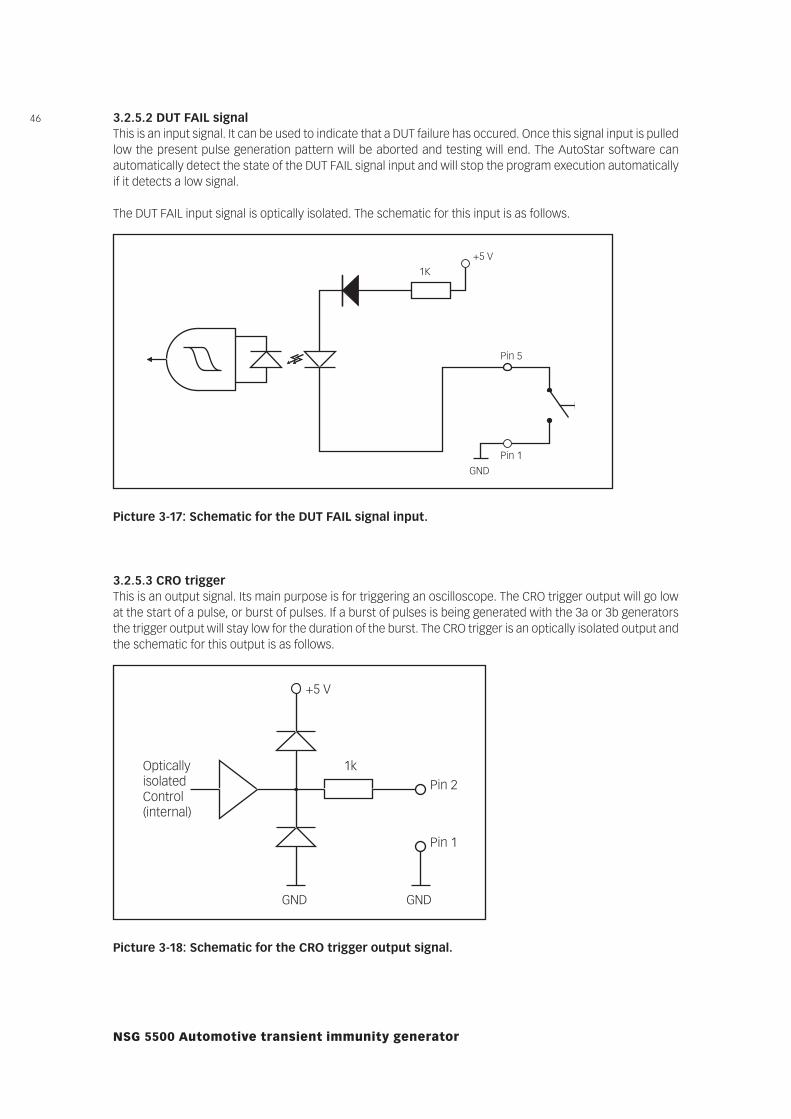
3.2.5.2 DUT FAIL signalThis is an input signal. It can be used to indicate that a DUT failure has occured. Once this signal input is pulled low the present pulse generation pattern will be aborted and testing will end. The AutoStar software can automatically detect the state of the DUT FAIL signal input and will stop the program execution automatically if it detects a low signal.
The DUT FAIL input signal is optically isolated. The schematic for this input is as follows.
1K+5 V
GNDPin 1
Pin 5
GNDGND
+5 V
1kPin 2
Pin 1
Optically isolated Control (internal)
Picture 3-17: Schematic for the DUT FAIL signal input.
3.2.5.3 CRO triggerThis is an output signal. Its main purpose is for triggering an oscilloscope. The CRO trigger output will go low at the start of a pulse, or burst of pulses. If a burst of pulses is being generated with the 3a or 3b generators the trigger output will stay low for the duration of the burst. The CRO trigger is an optically isolated output and the schematic for this output is as follows.
1K+5 V
GNDPin 1
Pin 5
GNDGND
+5 V
1kPin 2
Pin 1
Optically isolated Control (internal)
Picture 3-18: Schematic for the CRO trigger output signal.
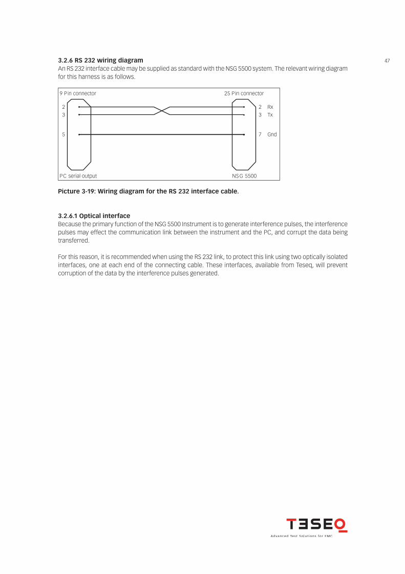
473.2.6 RS 232 wiring diagramAn RS 232 interface cable may be supplied as standard with the NSG 5500 system. The relevant wiring diagram for this harness is as follows.
connector niP 52connector niP 9
0055 GSN serial output CP
23
5
23
7
RxTx
Gnd
Picture 3-19: Wiring diagram for the RS 232 interface cable.
3.2.6.1 Optical interfaceBecause the primary function of the NSG 5500 Instrument is to generate interference pulses, the interference pulses may effect the communication link between the instrument and the PC, and corrupt the data being transferred.
For this reason, it is recommended when using the RS 232 link, to protect this link using two optically isolated interfaces, one at each end of the connecting cable. These interfaces, available from Teseq, will prevent corruption of the data by the interference pulses generated.
48
NSG 5500 Automotive transient immunity generator
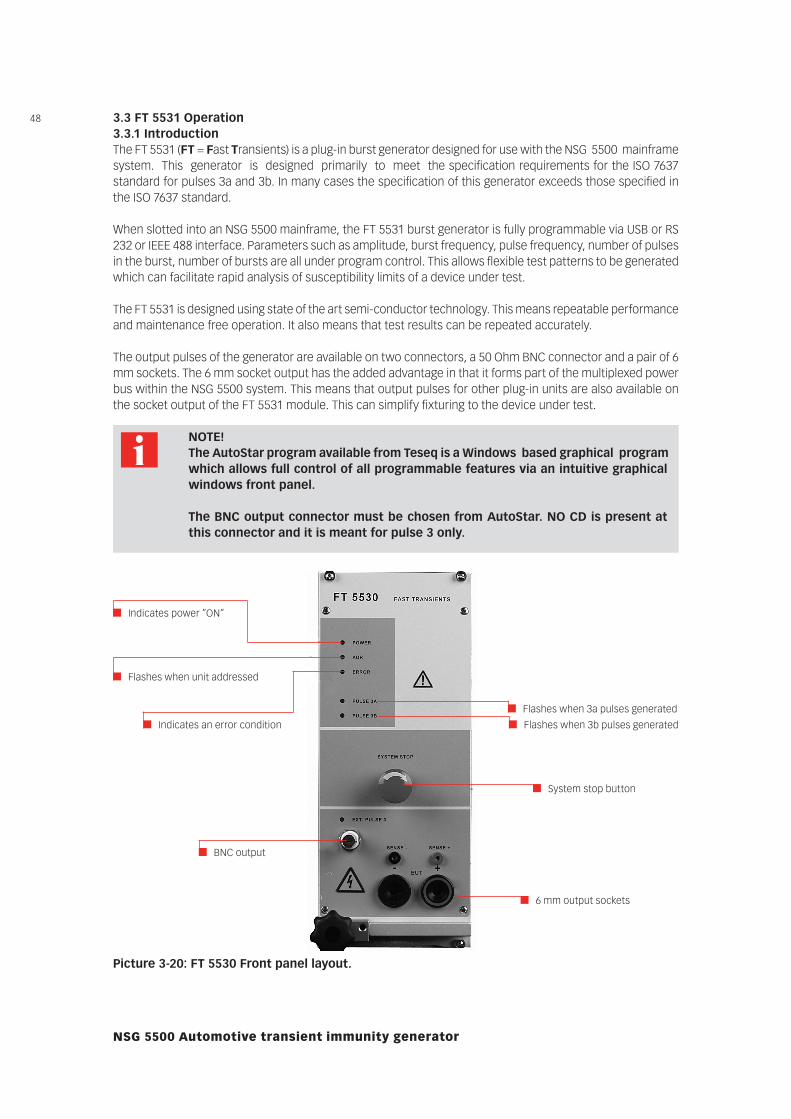
3.3 FT 5531 Operation3.3.1 IntroductionThe FT 5531 (FT = Fast Transients) is a plug-in burst generator designed for use with the NSG 5500 mainframe system. This generator is designed primarily to meet the specification requirements for the ISO 7637 standard for pulses 3a and 3b. In many cases the specification of this generator exceeds those specified in the ISO 7637 standard.
When slotted into an NSG 5500 mainframe, the FT 5531 burst generator is fully programmable via USB or RS 232 or IEEE 488 interface. Parameters such as amplitude, burst frequency, pulse frequency, number of pulses in the burst, number of bursts are all under program control. This allows flexible test patterns to be generated which can facilitate rapid analysis of susceptibility limits of a device under test.
The FT 5531 is designed using state of the art semi-conductor technology. This means repeatable performance and maintenance free operation. It also means that test results can be repeated accurately.
The output pulses of the generator are available on two connectors, a 50 Ohm BNC connector and a pair of 6 mm sockets. The 6 mm socket output has the added advantage in that it forms part of the multiplexed power bus within the NSG 5500 system. This means that output pulses for other plug-in units are also available on the socket output of the FT 5531 module. This can simplify fixturing to the device under test.
NOTE! The AutoStar program available from Teseq is a Windows based graphical program
which allows full control of all programmable features via an intuitive graphical windows front panel.
The BNC output connector must be chosen from AutoStar. NO CD is present at this connector and it is meant for pulse 3 only.
Picture 3-20: FT 5530 Front panel layout.
Indicates power ”ON”
Flashes when unit addressed
Indicates an error condition
BNC output
Flashes when 3a pulses generated
Flashes when 3b pulses generated
System stop button
6 mm output sockets
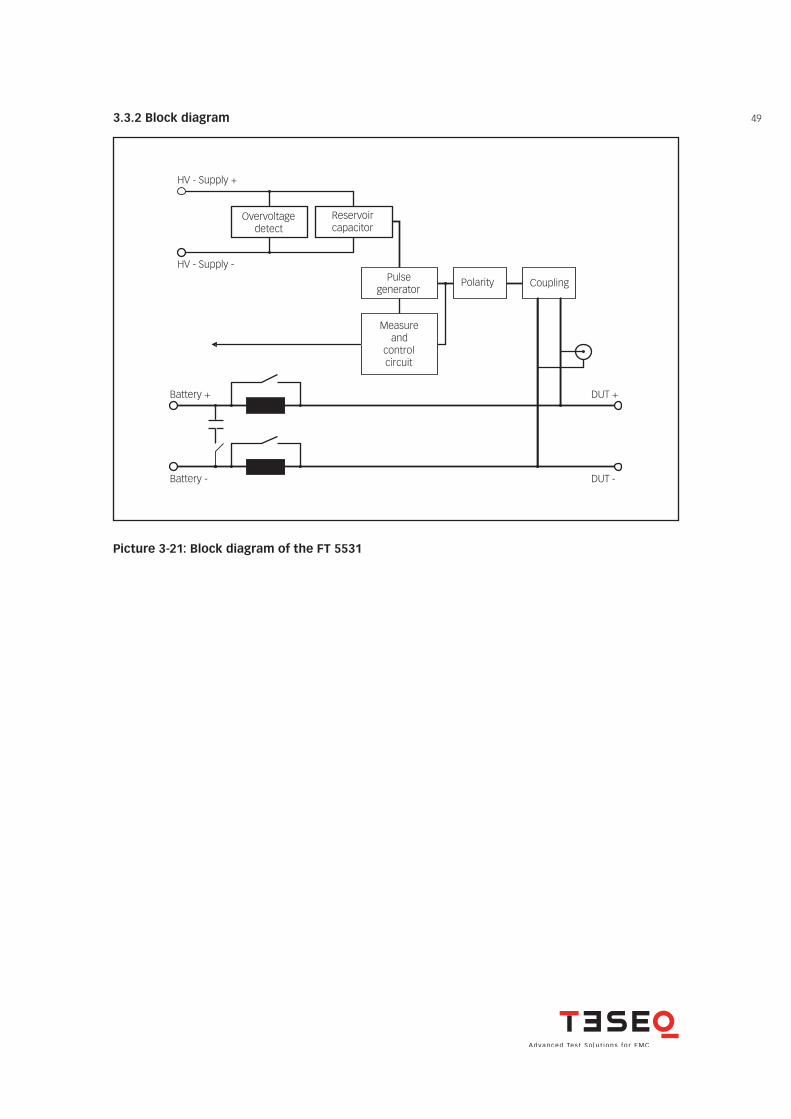
493.3.2 Block diagram
Overvoltage detect
Reservoir capacitor
HV - Supply +
HV - Supply -Pulse
generatorPolarity Coupling
Measure and
controlcircuit
Battery +
Battery -
DUT +
DUT -
Picture 3-21: Block diagram of the FT 5531
50
NSG 5500 Automotive transient immunity generator
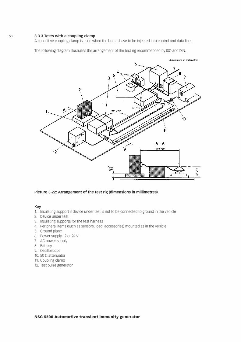
3.3.3 Tests with a coupling clampA capacitive coupling clamp is used when the bursts have to be injected into control and data lines.
The following diagram illustrates the arrangement of the test rig recommended by ISO and DIN.
Picture 3-22: Arrangement of the test rig (dimensions in millimetres).
Key1. Insulating support if device under test is not to be connected to ground in the vehicle2. Device under test3. Insulating supports for the test harness4. Peripheral items (such as sensors, load, accessories) mounted as in the vehicle5. Ground plane6. Power supply 12 or 24 V7. AC power supply8. Battery9. Oscilloscope10. 50 Ω attenuator11. Coupling clamp12. Test pulse generator
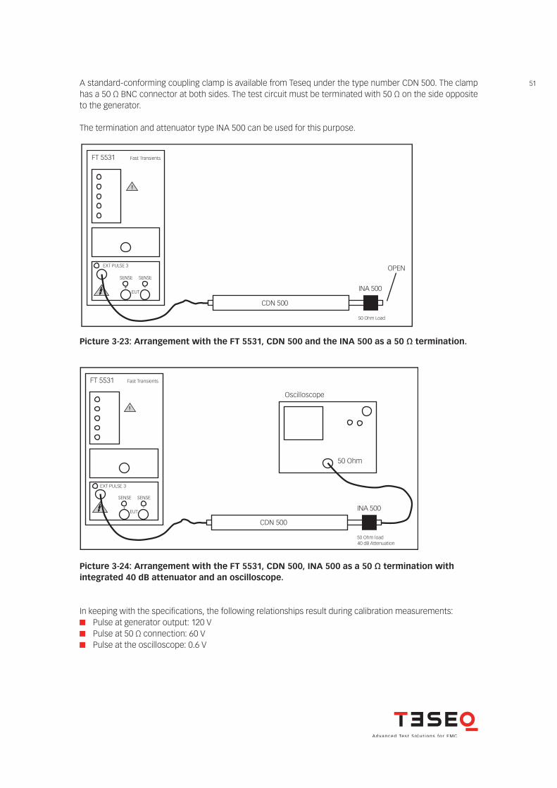
51A standard-conforming coupling clamp is available from Teseq under the type number CDN 500. The clamp has a 50 Ω BNC connector at both sides. The test circuit must be terminated with 50 Ω on the side opposite to the generator.
The termination and attenuator type INA 500 can be used for this purpose.
EXT PULSE 3
FT 5531 Fast Transients
CDN 500
50 Ohm load 40 dB Attenuation
50 Ohm
Oscilloscope
!
INA 500
EXT PULSE 3
EUT
FT 5531 Fast Transients
CDN 500
50 Ohm Load
OPEN
!
INA 500
SENSE SENSE
+ -
EUT
SENSE SENSE
+ -
Picture 3-23: Arrangement with the FT 5531, CDN 500 and the INA 500 as a 50 Ω termination.
EXT PULSE 3
FT 5531 Fast Transients
CDN 500
50 Ohm load 40 dB Attenuation
50 Ohm
Oscilloscope
!
INA 500
EXT PULSE 3
EUT
FT 5531 Fast Transients
CDN 500
50 Ohm Load
OPEN
!
INA 500
SENSE SENSE
+ -
EUT
SENSE SENSE
+ -
Picture 3-24: Arrangement with the FT 5531, CDN 500, INA 500 as a 50 Ω termination withintegrated 40 dB attenuator and an oscilloscope.
In keeping with the specifications, the following relationships result during calibration measurements: Pulse at generator output: 120 V Pulse at 50 Ω connection: 60 V Pulse at the oscilloscope: 0.6 V
52
NSG 5500 Automotive transient immunity generator
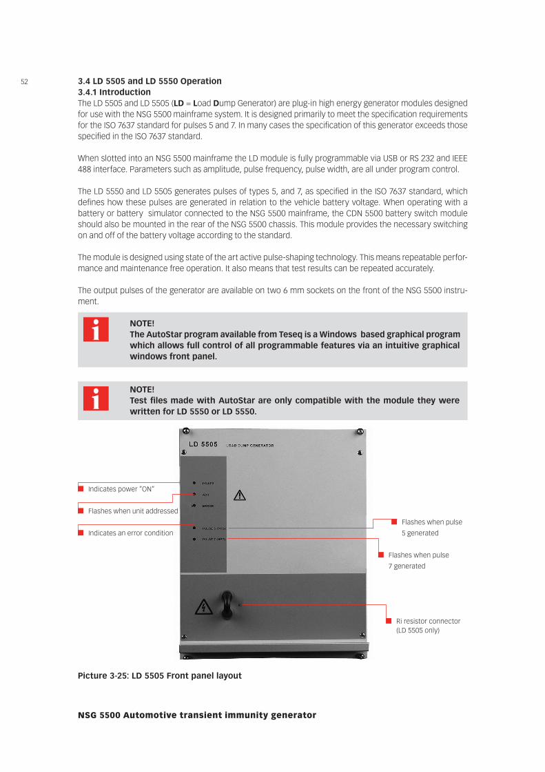
3.4 LD 5505 and LD 5550 Operation3.4.1 IntroductionThe LD 5505 and LD 5505 (LD = Load Dump Generator) are plug-in high energy generator modules designed for use with the NSG 5500 mainframe system. It is designed primarily to meet the specification requirements for the ISO 7637 standard for pulses 5 and 7. In many cases the specification of this generator exceeds those specified in the ISO 7637 standard.
When slotted into an NSG 5500 mainframe the LD module is fully programmable via USB or RS 232 and IEEE 488 interface. Parameters such as amplitude, pulse frequency, pulse width, are all under program control.
The LD 5550 and LD 5505 generates pulses of types 5, and 7, as specified in the ISO 7637 standard, which defines how these pulses are generated in relation to the vehicle battery voltage. When operating with a battery or battery simulator connected to the NSG 5500 mainframe, the CDN 5500 battery switch module should also be mounted in the rear of the NSG 5500 chassis. This module provides the necessary switching on and off of the battery voltage according to the standard.
The module is designed using state of the art active pulse-shaping technology. This means repeatable perfor-mance and maintenance free operation. It also means that test results can be repeated accurately.
The output pulses of the generator are available on two 6 mm sockets on the front of the NSG 5500 instru-ment.
NOTE! The AutoStar program available from Teseq is a Windows based graphical program
which allows full control of all programmable features via an intuitive graphical windows front panel.
Picture 3-25: LD 5505 Front panel layout
Indicates power ”ON”
Flashes when unit addressed
Indicates an error condition
Flashes when pulse
5 generated
Flashes when pulse
7 generated
Ri resistor connector (LD 5505 only)
NOTE! Test files made with AutoStar are only compatible with the module they were
written for LD 5550 or LD 5550.
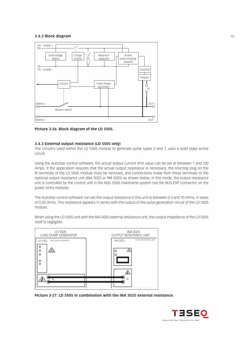
533.4.2 Block diagram
Overvoltage detect
Reservoir capacitor
HV - Supply +
HV - Supply -
Pulse shape generator
Polarity
Coupling
Battery +
Battery -
DUT +
DUT -
Charge control
Active pulse-shaping
network
Control
Ri
Battery switch
Picture 3-26: Block diagram of the LD 5505.
3.4.3 External output resistance (LD 5505 only)The circuitry used within the LD 5505 module to generate pulse types 5 and 7, uses a solid state active circuit.
Using the AutoStar control software, the actual output current limit value can be set at between 1 and 120 Amps. If the application requires that the actual output resistance is necessary, the shorting plug on the Ri terminals of the LD 5505 module must be removed, and connections made from these terminals to the optional output resistance unit (INA 5025 or RM 5055) as shown below. In this mode, the output resistance unit is controlled by the control unit in the NSG 5500 mainframe system (via the BUS EXP connector on the power entry module).
The AutoStar control software can set the output resistance in this unit to between 0.5 and 10 ohms, in steps of 0.25 ohms. This resistance appears in series with the output of the pulse generation circuit of the LD 5505 module.
When using the LD 5505 unit with the INA 5025 external resistance unit, the output impedance of the LD 5505 itself is negligible.
LD 5505 LOAD DUMP GENERATOR
!
Ri
INA 5025 OUTPUT RESISTANCE UNIT
Ri
!
LD 5505 LOAD DUMP GENERATOR
INA 5025 OUTPUT RESISTANCE UNIT
Picture 3-27: LD 5505 in combination with the INA 5025 external resistance.
54
NSG 5500 Automotive transient immunity generator
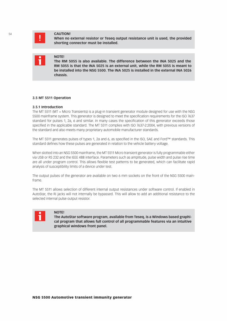
CAUTION! When no external resistor or Teseq output resistance unit is used, the provided
shorting connector must be installed.
NOTE! The RM 5055 is also available. The difference between the INA 5025 and the
RM 5055 is that the INA 5025 is an external unit, while the RM 5055 is meant to be installed into the NSG 5500. The INA 5025 is installed in the external INA 5026 chassis.
3.5 MT 5511 Operation
3.5.1 IntroductionThe MT 5511 (MT = Micro Transients) is a plug-in transient generator module designed for use with the NSG 5500 mainframe system. This generator is designed to meet the specification requirements for the ISO 7637 standard for pulses 1, 2a, 6 and similar. In many cases the specification of this generator exceeds those specified in the applicable standard. The MT 5511 complies with ISO 7637-2:2004, with previous versions of the standard and also meets many proprietary automobile manufacturer standards.
The MT 5511 generates pulses of types 1, 2a and 6, as specified in the ISO, SAE and Ford™ standards. This standard defines how these pulses are generated in relation to the vehicle battery voltage.
When slotted into an NSG 5500 mainframe, the MT 5511 Micro transient generator is fully programmable either via USB or RS 232 and the IEEE 488 interface. Parameters such as amplitude, pulse width and pulse rise time are all under program control. This allows flexible test patterns to be generated, which can facilitate rapid analysis of susceptibility limits of a device under test.
The output pulses of the generator are available on two 6 mm sockets on the front of the NSG 5500 main-frame.
The MT 5511 allows selection of different internal output resistances under software control. If enabled in AutoStar, the Ri jacks will not internally be bypassed. This will allow to add an additional resistance to the selected internal pulse output resistor.
NOTE! The AutoStar software program, available from Teseq, is a Windows based graphi-
cal program that allows full control of all programmable features via an intuitive graphical windows front panel.
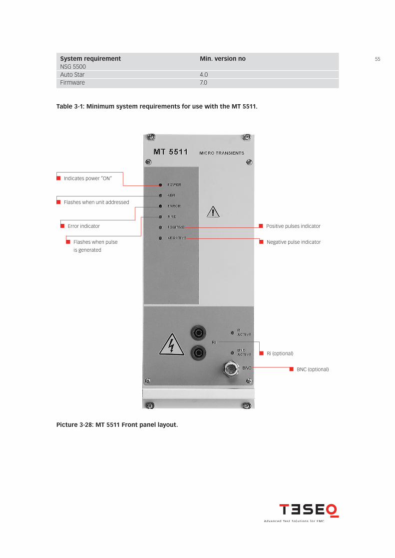
55System requirement Min. version noNSG 5500 Auto Star 4.0Firmware 7.0
Table 3-1: Minimum system requirements for use with the MT 5511.
Indicates power ”ON”
Flashes when unit addressed
Error indicator Positive pulses indicator
Negative pulse indicator
Ri (optional)
Flashes when pulse
is generated
Picture 3-28: MT 5511 Front panel layout.
BNC (optional)
56
NSG 5500 Automotive transient immunity generator
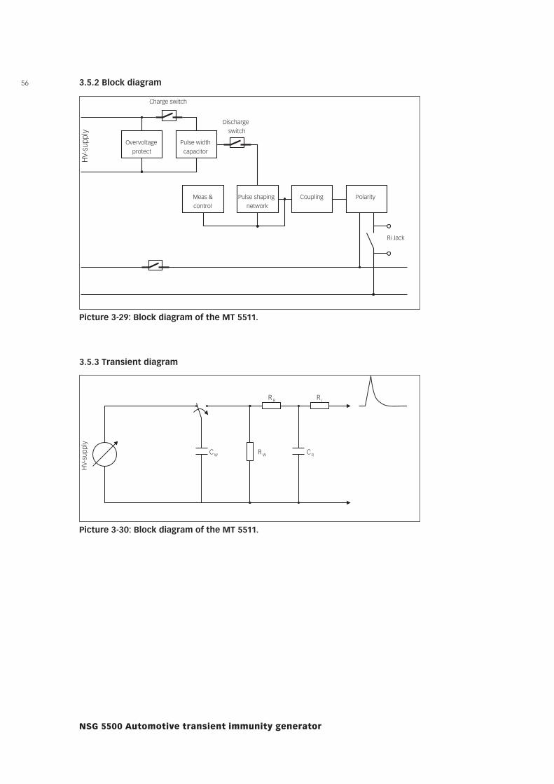
3.5.2 Block diagram
Overvoltage protect
Pulse width capacitor
Meas & control
Pulse shaping network
Coupling Polarity
Charge switch
Discharge switch
HV-
supp
ly
Ri Jack
Picture 3-29: Block diagram of the MT 5511.
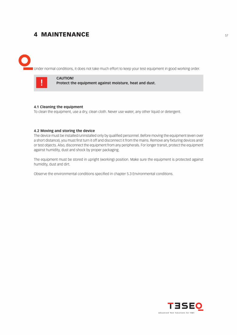
3.5.3 Transient diagram
HV-supp
ly
CW RW CR
R R R i
Picture 3-30: Block diagram of the MT 5511.
57
Under normal conditions, it does not take much effort to keep your test equipment in good working order.
4 MAINTENANCE
CAUTION! Protect the equipment against moisture, heat and dust.
4.1 Cleaning the equipmentTo clean the equipment, use a dry, clean cloth. Never use water, any other liquid or detergent.
4.2 Moving and storing the deviceThe device must be installed/uninstalled only by qualifi ed personnel. Before moving the equipment (even over a short distance), you must fi rst turn it off and disconnect it from the mains. Remove any fi xturing devices and/or test objects. Also, disconnect the equipment from any peripherals. For longer transit, protect the equipment against humidity, dust and shock by proper packaging.
The equipment must be stored in upright (working) position. Make sure the equipment is protected against humidity, dust and dirt.
Observe the environmental conditions specifi ed in chapter 5.3 Environmental conditions.
58
NSG 5500 Automotive transient immunity generator
4.3 Protection
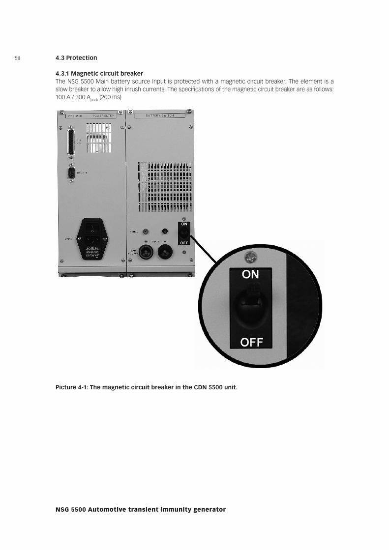
4.3.1 Magnetic circuit breakerThe NSG 5500 Main battery source Input is protected with a magnetic circuit breaker. The element is a slow breaker to allow high inrush currents. The specifications of the magnetic circuit breaker are as follows: 100 A / 300 Apeak (200 ms)
Picture 4-1: The magnetic circuit breaker in the CDN 5500 unit.
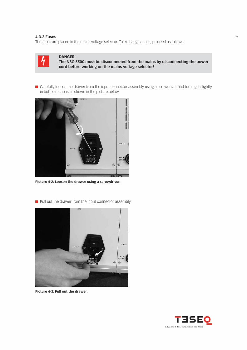
594.3.2 FusesThe fuses are placed in the mains voltage selector. To exchange a fuse, proceed as follows:
DANGER! The NSG 5500 must be disconnected from the mains by disconnecting the power
cord before working on the mains voltage selector!
Carefully loosen the drawer from the input connector assembly using a screwdriver and turning it slightly in both directions as shown in the picture below.
Picture 4-2: Loosen the drawer using a screwdriver.
Pull out the drawer from the input connector assembly
Picture 4-3: Pull out the drawer.
60
NSG 5500 Automotive transient immunity generator
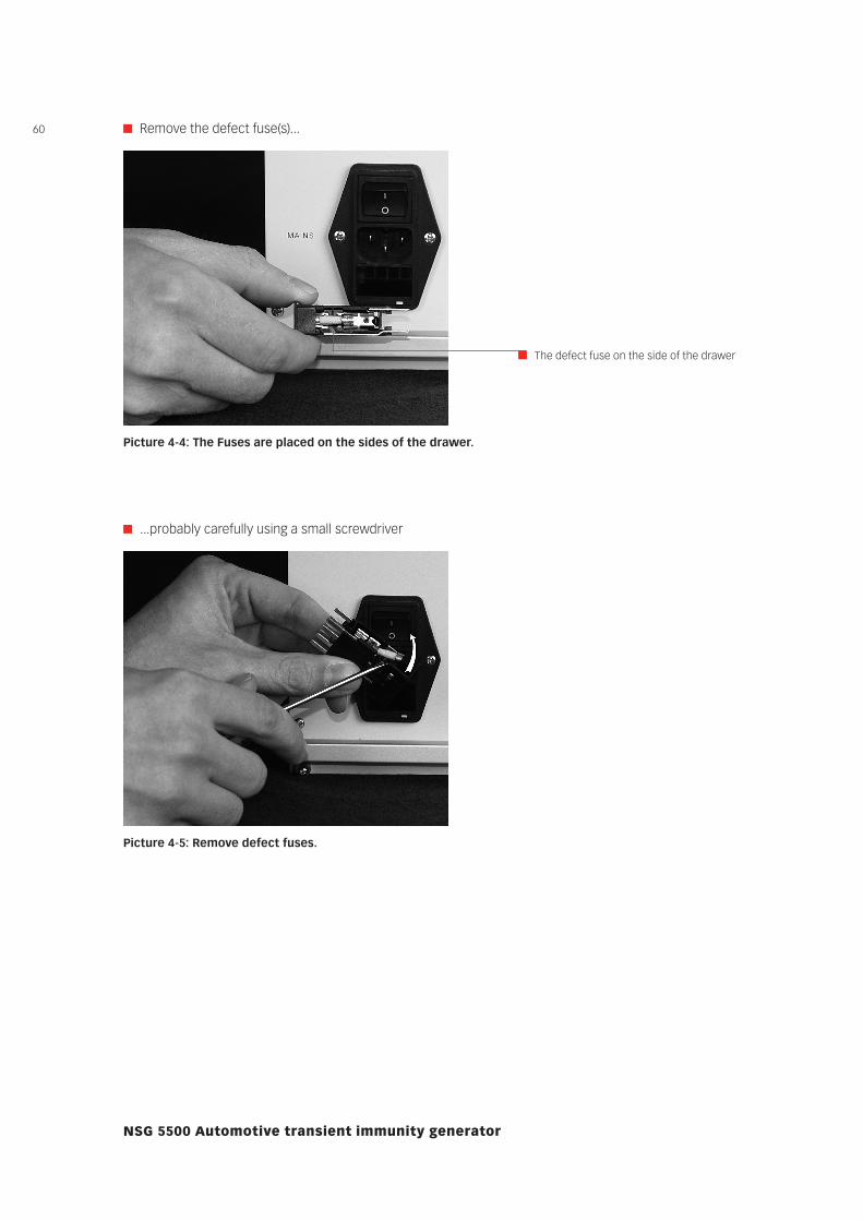
Remove the defect fuse(s)...
Picture 4-4: The Fuses are placed on the sides of the drawer.
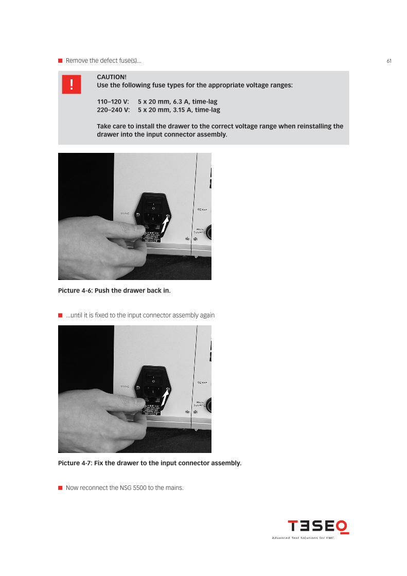
...probably carefully using a small screwdriver
Picture 4-5: Remove defect fuses.
The defect fuse on the side of the drawer
61 Remove the defect fuse(s)...
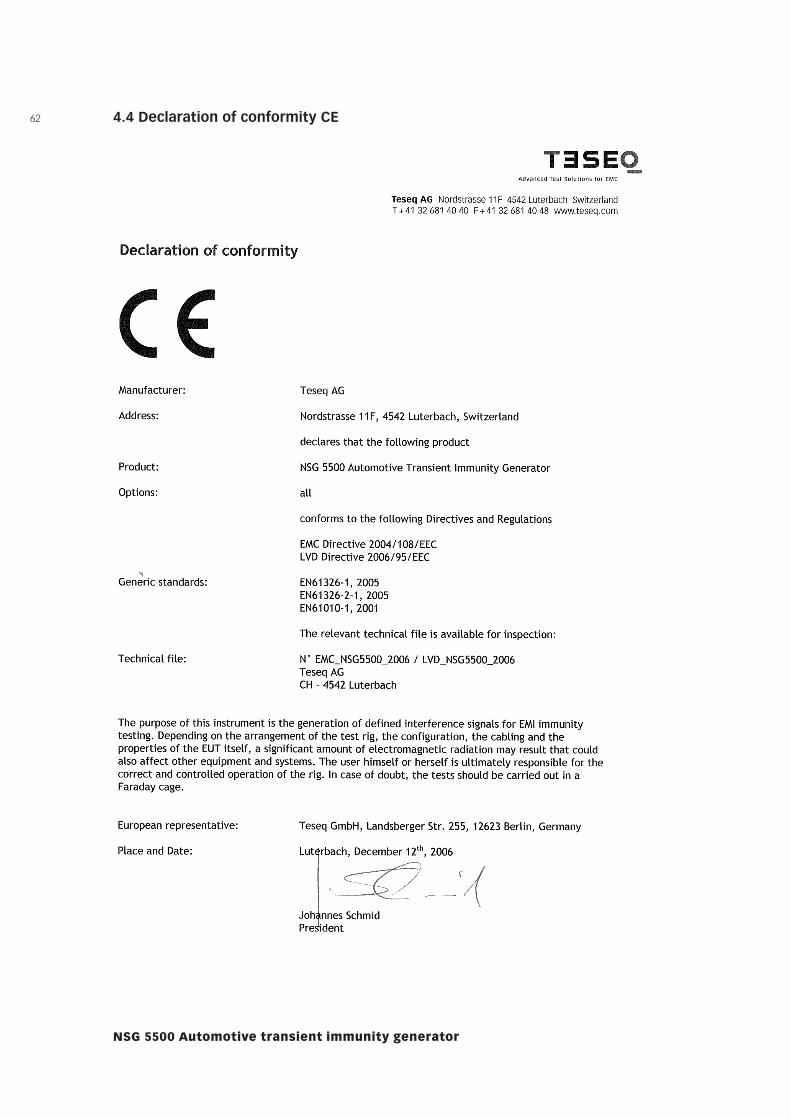
Picture 4-6: Push the drawer back in.
CAUTION! Use the following fuse types for the appropriate voltage ranges:
110–120 V: 5 x 20 mm, 6.3 A, time-lag 220–240 V: 5 x 20 mm, 3.15 A, time-lag
Take care to install the drawer to the correct voltage range when reinstalling the drawer into the input connector assembly.
Picture 4-7: Fix the drawer to the input connector assembly.
...until it is fixed to the input connector assembly again
Now reconnect the NSG 5500 to the mains.
62
NSG 5500 Automotive transient immunity generator
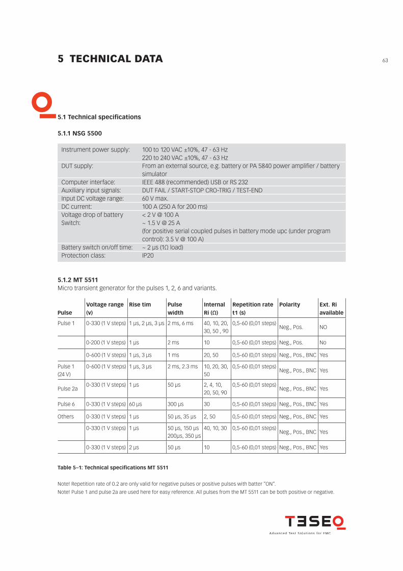
4.4 Declaration of conformity CE
635 TECHNICAL DATA
5.1 Technical specifications
5.1.1 NSG 5500
Instrument power supply: 100 to 120 VAC ±10%, 47 - 63 Hz 220 to 240 VAC ±10%, 47 - 63 HzDUT supply: From an external source, e.g. battery or PA 5840 power amplifi er / battery simulatorComputer interface: IEEE 488 (recommended) USB or RS 232Auxiliary input signals: DUT FAIL / START-STOP CRO-TRIG / TEST-ENDInput DC voltage range: 60 V max.DC current: 100 A (250 A for 200 ms)Voltage drop of battery < 2 V @ 100 ASwitch: ~ 1.5 V @ 25 A (for positive serial coupled pulses in battery mode upc (under program control): 3.5 V @ 100 A)Battery switch on/off time: ~ 2 µs (1Ω load)Protection class: IP20
5.1.2 MT 5511Micro transient generator for the pulses 1, 2, 6 and variants.
PulseVoltage range (v)
Rise tim Pulse width
Internal Ri (Ω)
Repetition rate t1 (s)
Polarity Ext. Ri available
Pulse 1 0-330 (1 V steps) 1 µs, 2 µs, 3 µs 2 ms, 6 ms 40, 10, 20, 30, 50 , 90
0,5-60 (0,01 steps)Neg., Pos. NO
0-200 (1 V steps) 1 µs 2 ms 10 0,5-60 (0,01 steps) Neg., Pos. No
0-600 (1 V steps) 1 µs, 3 µs 1 ms 20, 50 0,5-60 (0,01 steps) Neg., Pos., BNC Yes
Pulse 1 (24 V)
0-600 (1 V steps) 1 µs, 3 µs 2 ms, 2.3 ms 10, 20, 30, 50
0,5-60 (0,01 steps)Neg., Pos., BNC Yes
Pulse 2a0-330 (1 V steps) 1 µs 50 µs 2, 4, 10,
20, 50, 900,5-60 (0,01 steps)
Neg., Pos., BNC Yes
Pulse 6 0-330 (1 V steps) 60 µs 300 µs 30 0,5-60 (0,01 steps) Neg., Pos., BNC Yes
Others 0-330 (1 V steps) 1 µs 50 µs, 35 µs 2, 50 0,5-60 (0,01 steps) Neg., Pos., BNC Yes
0-330 (1 V steps) 1 µs 50 µs, 150 µs200µs, 350 µs
40, 10, 30 0,5-60 (0,01 steps)Neg., Pos., BNC Yes
0-330 (1 V steps) 2 µs 50 µs 10 0,5-60 (0,01 steps) Neg., Pos., BNC Yes
Table 5–1: Technical specifications MT 5511
Note! Repetition rate of 0.2 are only valid for negative pulses or positive pulses with batter ”ON”.
Note! Pulse 1 and pulse 2a are used here for easy reference. All pulses from the MT 5511 can be both positive or negative.
64
NSG 5500 Automotive transient immunity generator
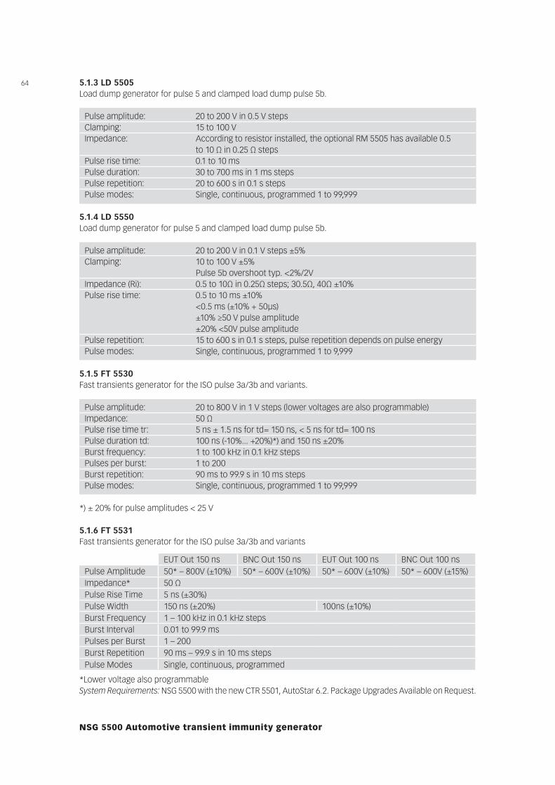
5.1.3 LD 5505Load dump generator for pulse 5 and clamped load dump pulse 5b.
Pulse amplitude: 20 to 800 V in 1 V steps (lower voltages are also programmable)Impedance: 50 ΩPulse rise time tr: 5 ns ± 1.5 ns for td= 150 ns, < 5 ns for td= 100 nsPulse duration td: 100 ns (-10%... +20%)*) and 150 ns ±20%Burst frequency: 1 to 100 kHz in 0.1 kHz stepsPulses per burst: 1 to 200Burst repetition: 90 ms to 99.9 s in 10 ms stepsPulse modes: Single, continuous, programmed 1 to 99,999
*) ± 20% for pulse amplitudes < 25 V
*Lower voltage also programmableSystem Requirements: NSG 5500 with the new CTR 5501, AutoStar 6.2. Package Upgrades Available on Request.
5.1.5 FT 5530Fast transients generator for the ISO pulse 3a/3b and variants.
5.1.6 FT 5531Fast transients generator for the ISO pulse 3a/3b and variants
EUT Out 150 ns BNC Out 150 ns EUT Out 100 ns BNC Out 100 nsPulse Amplitude 50* – 800V (±10%) 50* – 600V (±10%) 50* – 600V (±10%) 50* – 600V (±15%)Impedance* 50 ΩPulse Rise Time 5 ns (±30%)Pulse Width 150 ns (±20%) 100ns (±10%)Burst Frequency 1 – 100 kHz in 0.1 kHz stepsBurst Interval 0.01 to 99.9 msPulses per Burst 1 – 200Burst Repetition 90 ms – 99.9 s in 10 ms stepsPulse Modes Single, continuous, programmed
Pulse amplitude: 20 to 200 V in 0.5 V stepsClamping: 15 to 100 VImpedance: According to resistor installed, the optional RM 5505 has available 0.5 to 10 Ω in 0.25 Ω stepsPulse rise time: 0.1 to 10 msPulse duration: 30 to 700 ms in 1 ms stepsPulse repetition: 20 to 600 s in 0.1 s stepsPulse modes: Single, continuous, programmed 1 to 99,999
Pulse amplitude: 20 to 200 V in 0.1 V steps ±5%Clamping: 10 to 100 V ±5% Pulse 5b overshoot typ. <2%/2VImpedance (Ri): 0.5 to 10Ω in 0.25Ω steps; 30.5Ω, 40Ω ±10%Pulse rise time: 0.5 to 10 ms ±10% <0.5 ms (±10% + 50μs) ±10% ≥50 V pulse amplitude ±20% <50V pulse amplitudePulse repetition: 15 to 600 s in 0.1 s steps, pulse repetition depends on pulse energyPulse modes: Single, continuous, programmed 1 to 9,999
5.1.4 LD 5550Load dump generator for pulse 5 and clamped load dump pulse 5b.
65
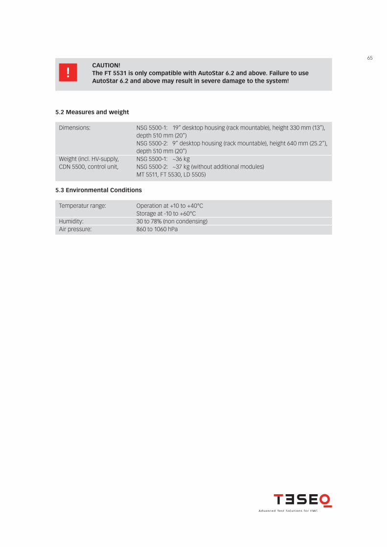
5.2 Measures and weight
Dimensions: NSG 5500-1: 19” desktop housing (rack mountable), height 330 mm (13”), depth 510 mm (20”) NSG 5500-2: 9” desktop housing (rack mountable), height 640 mm (25.2”), depth 510 mm (20”)Weight (incl. HV-supply, NSG 5500-1: ~36 kg CDN 5500, control unit, NSG 5500-2: ~37 kg (without additional modules) MT 5511, FT 5530, LD 5505)
5.3 Environmental Conditions
Temperatur range: Operation at +10 to +40°C Storage at -10 to +60°CHumidity: 30 to 78% (non condensing)Air pressure: 860 to 1060 hPa
CAUTION! The FT 5531 is only compatible with AutoStar 6.2 and above. Failure to use AutoStar 6.2 and above may result in severe damage to the system!
66
To find your local partner withinTeseq®’s global network, please go to www.teseq.com© October 2013 Teseq®
Specifications subject to change without notice. Teseq® is an ISO-registered company. Its products are designed and manufactured under the strict quality and environmental requirements of the ISO 9001. This document has been carefully checked. However, Teseq® does not assume any liability for errors or inaccuracies.
HeadquartersTeseq AG4542 Luterbach, SwitzerlandT + 41 32 681 40 40F + 41 32 681 40 48sales @ teseq.comwww.teseq.com
ChinaTeseq Company LimitedT + 86 10 8460 8080F + 86 10 8460 8078chinasales @ teseq.com
GermanyTeseq GmbHT + 49 30 5659 8835F + 49 30 5659 8834desales @ teseq.com
SingaporeTeseq Pte Ltd.T + 65 6846 2488F + 65 6841 4282singaporesales @ teseq.com
TaiwanTeseq Ltd.T + 886 2 2917 8080F + 886 2 2917 2626taiwansales @ teseq.com
USATeseq Inc.T + 1 732 417 0501F + 1 732 417 0511Toll free +1 888 417 0501usasales @ teseq.com
ManufacturerTeseq AG4542 Luterbach, SwitzerlandT + 41 32 681 40 40F + 41 32 681 40 48sales @ teseq.com
FranceTeseq SarlT + 33 1 39 47 42 21F + 33 1 39 47 40 92francesales @ teseq.com
JapanTeseq K.K.T + 81 3 5725 9460F + 81 3 5725 9461japansales @t eseq.com
SwitzerlandTeseq AGT + 41 32 681 40 50F + 41 32 681 40 48sales @ teseq.com
UKTeseq Ltd.T + 44 845 074 0660F + 44 845 074 0656uksales @ teseq.com